

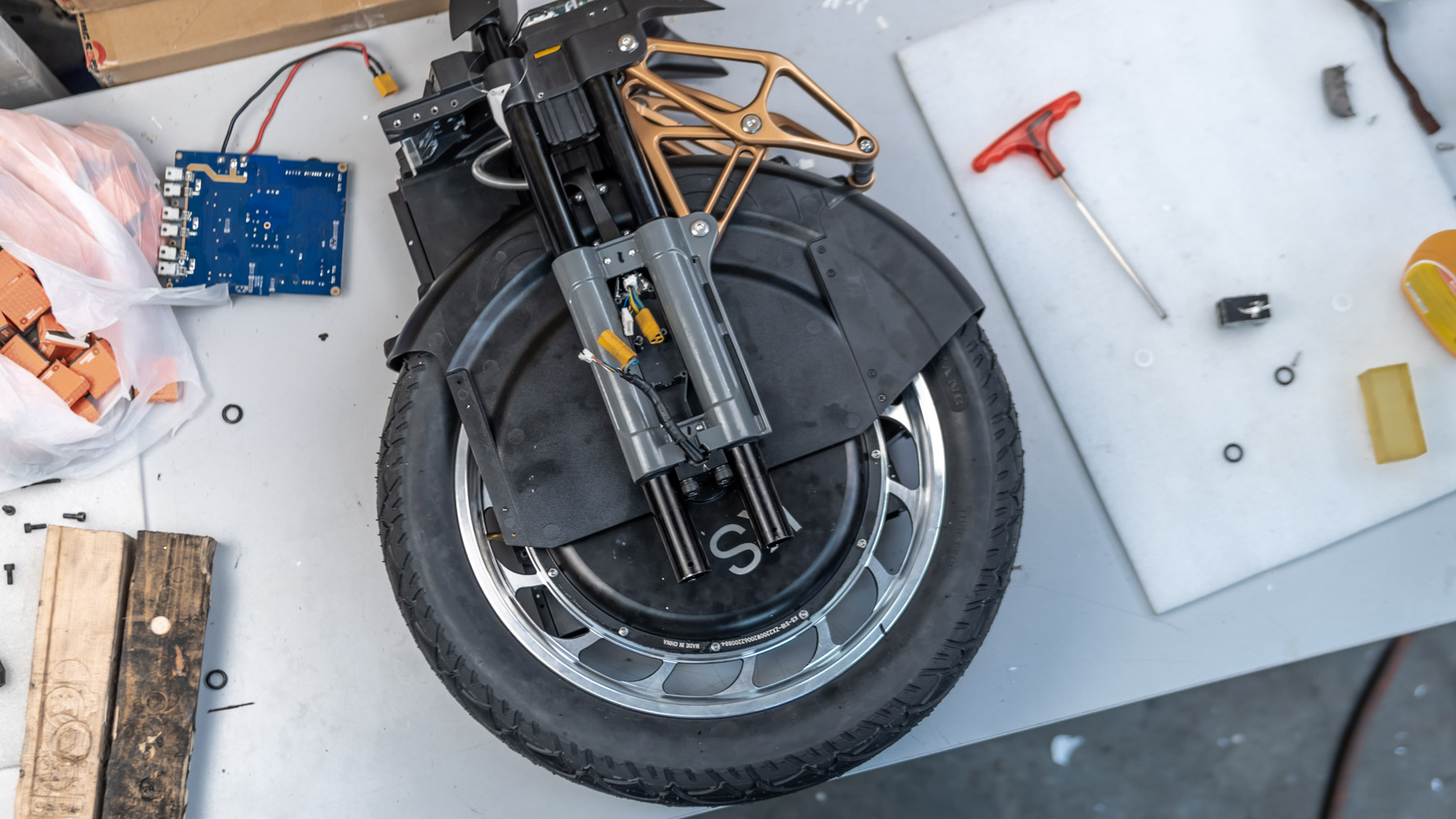
Today I will tell you how I rebuilt the suspension on the wheel from the first batch. Perhaps, the manufacturer will introduce some changes and improvements to the next batches. Therefore some parts may be different in the future.
I will not dwell on disassembling the wheel in detail. If you have any questions, watch the video from Kingsong.
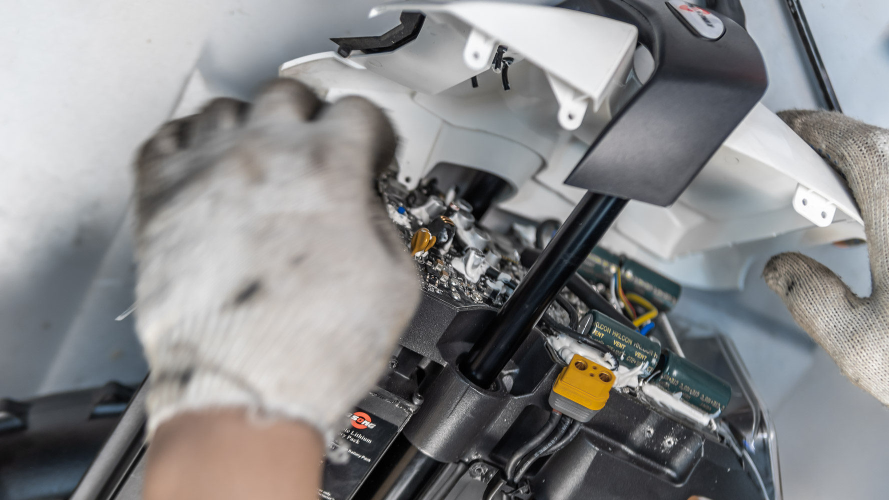
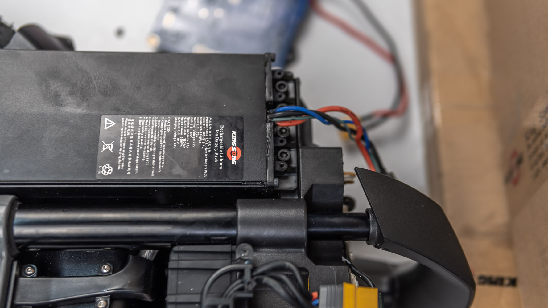
After removing the top cover, we will need to remove the cover of the controller and disconnect the terminals from the battery. Then press the power button to discharge the capacitors.
Then we disconnect the engine.
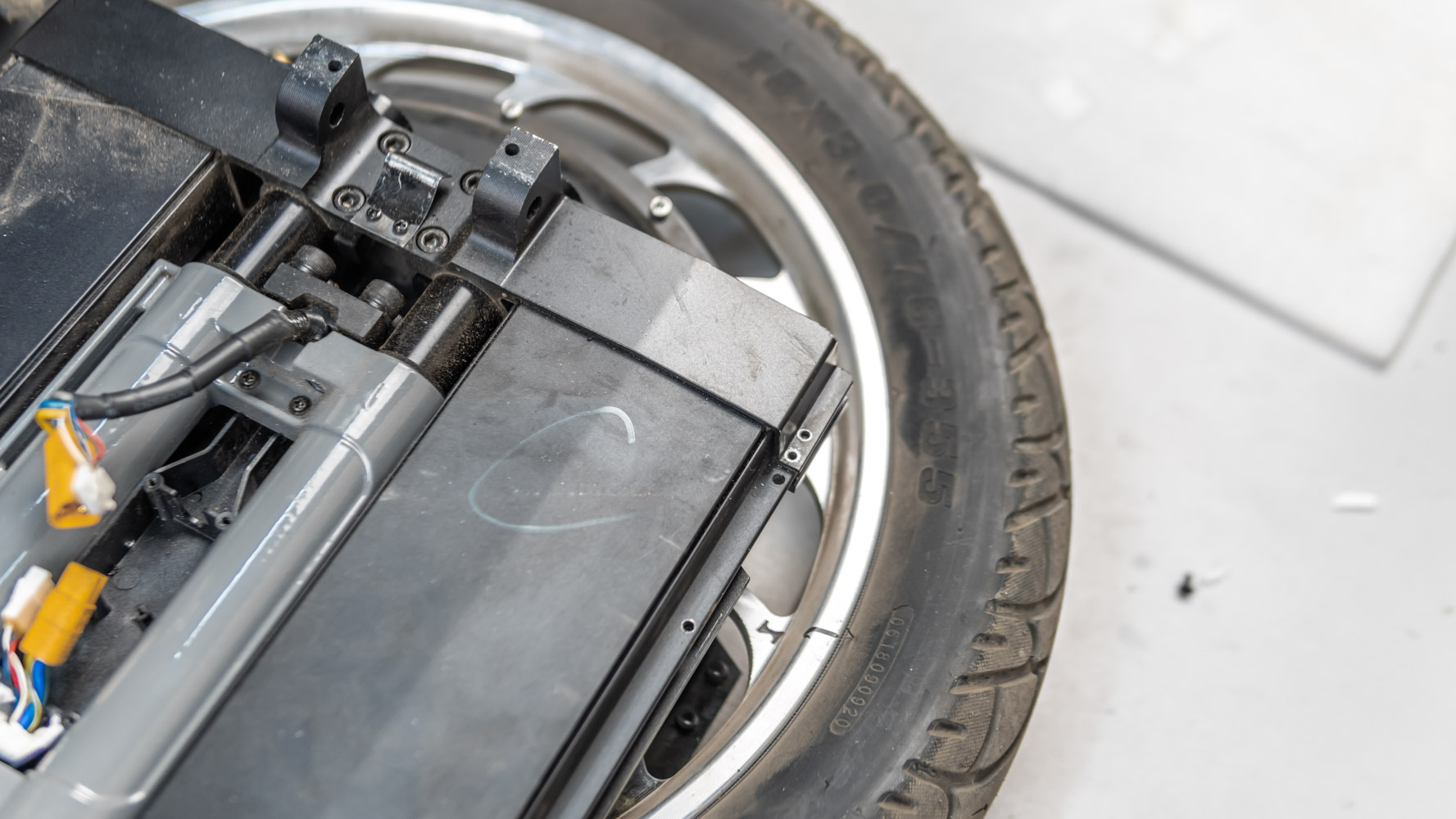
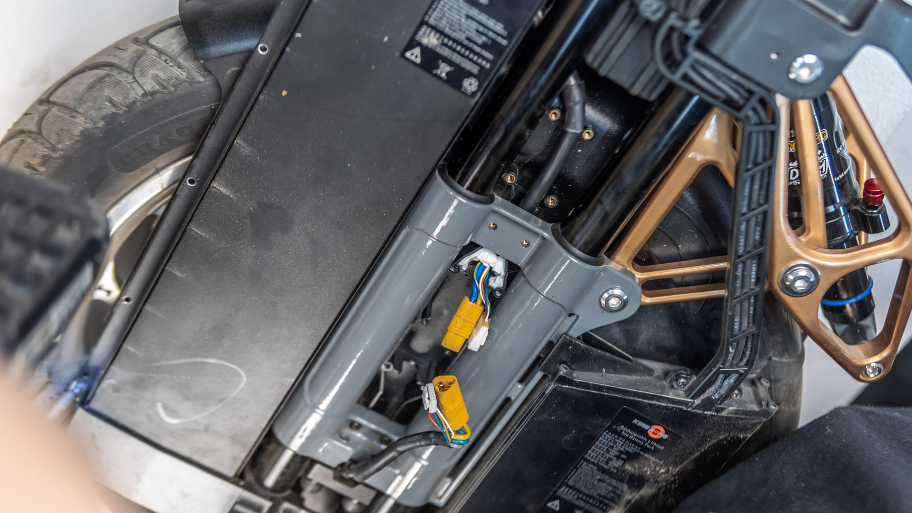
Unscrew the batteries.
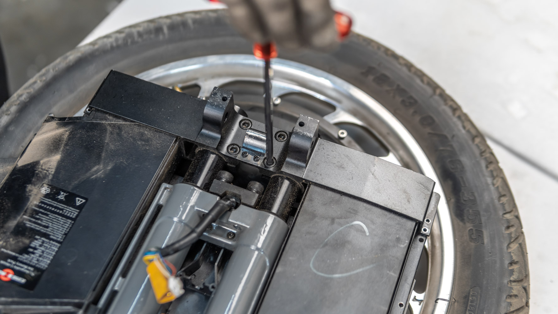
We unscrew what Kingsong calls the “battery base” (and I call them “underpants”) by undoing the four screws in the base one by one. Remove this base and the battery packs.
Remove the wires.

Bleed the tire and pull out the engine.
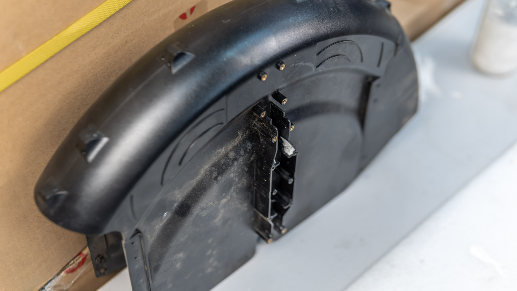
Then we remove the mud protector.
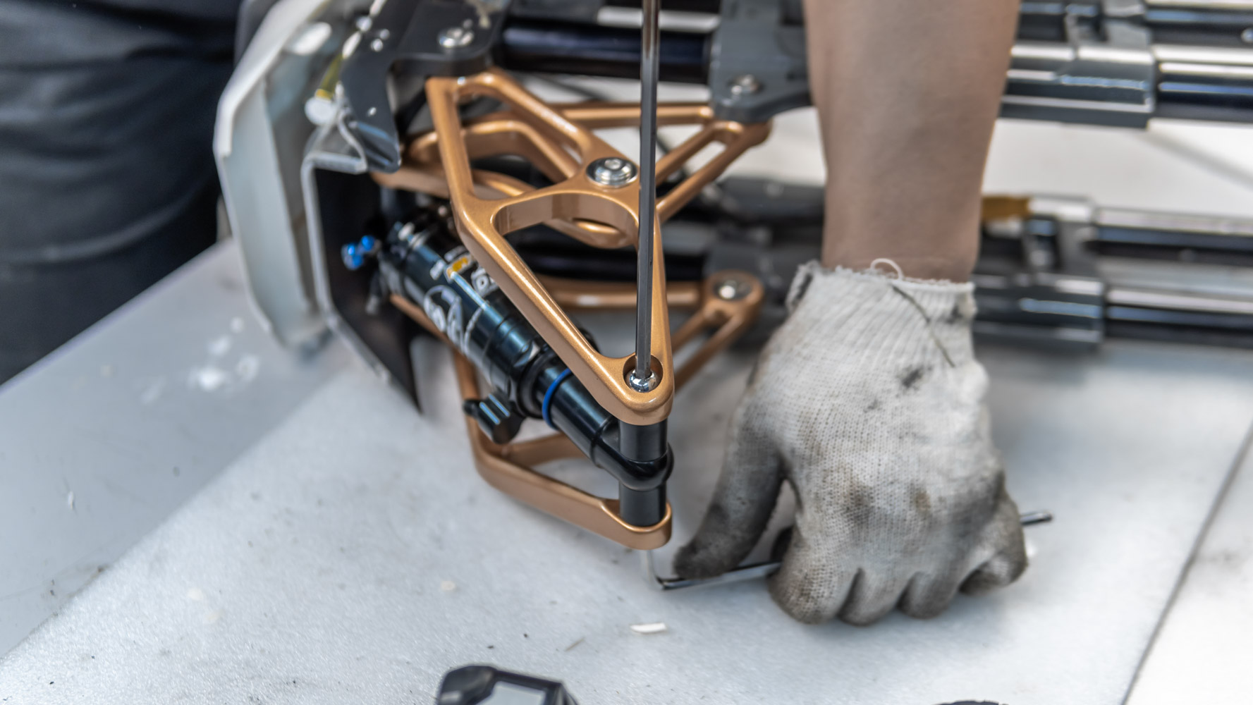
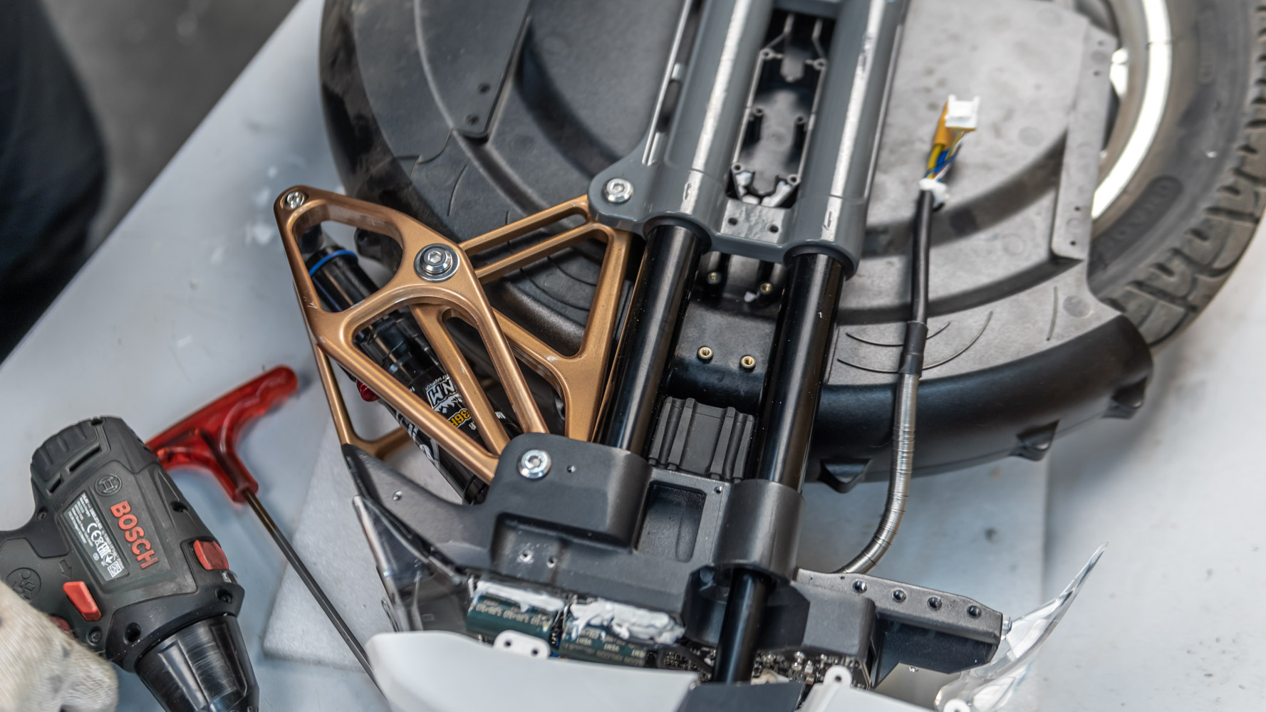
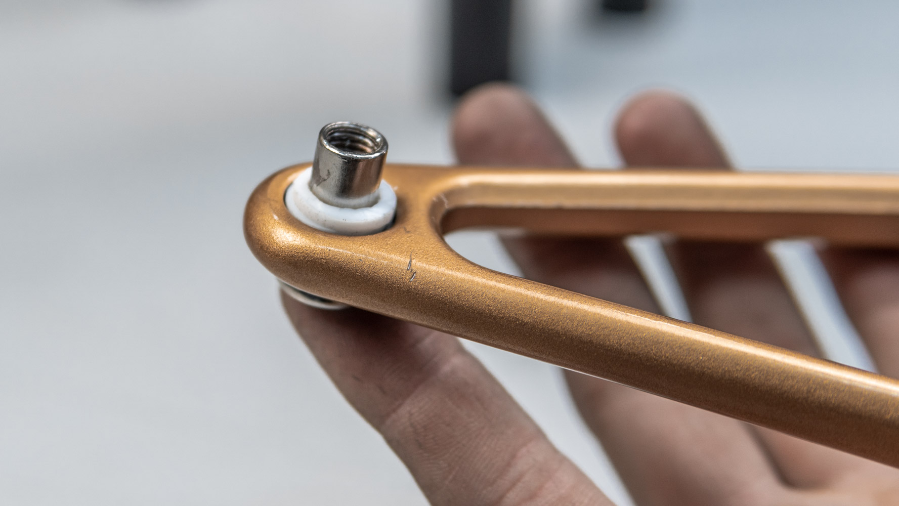
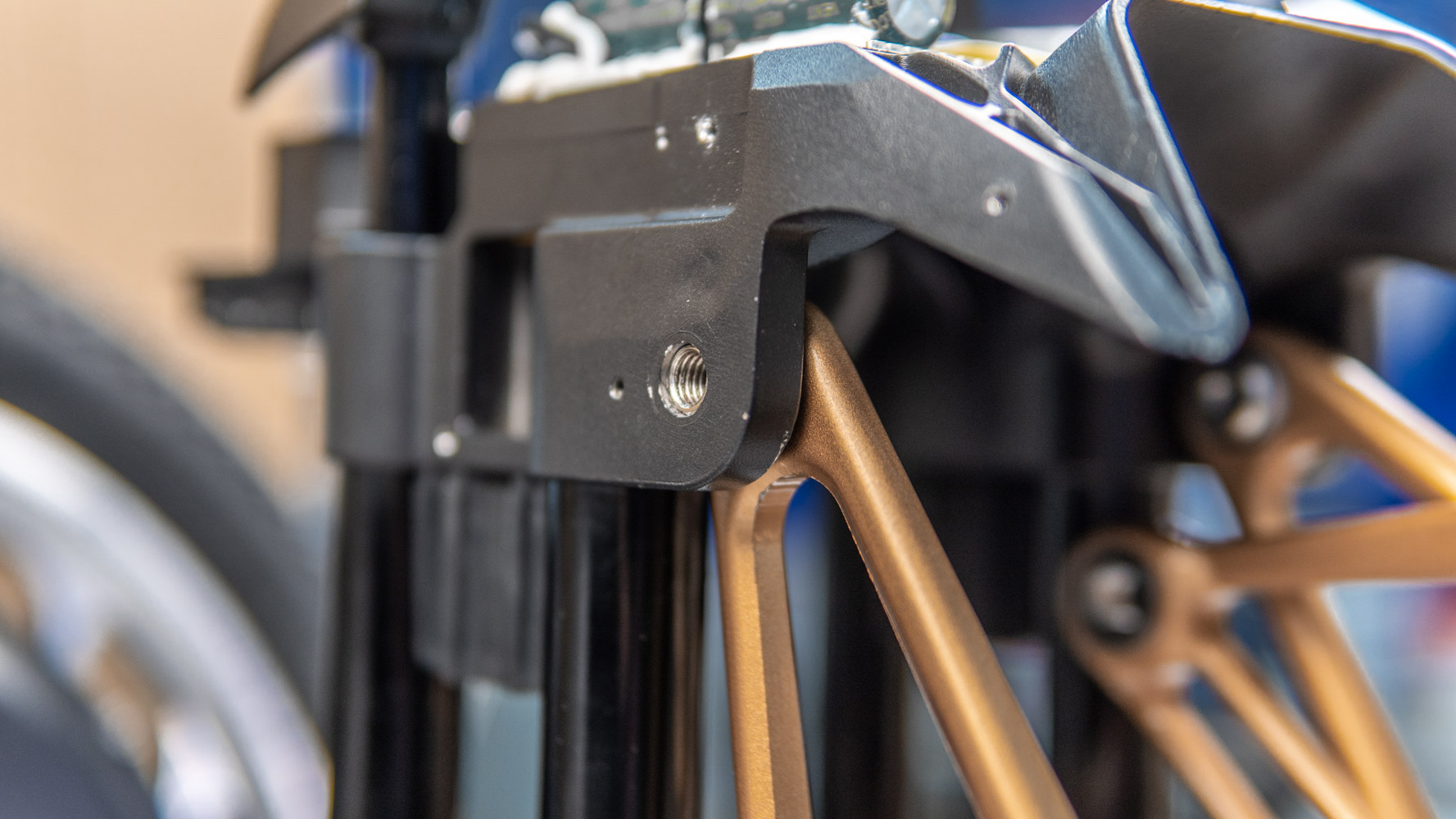
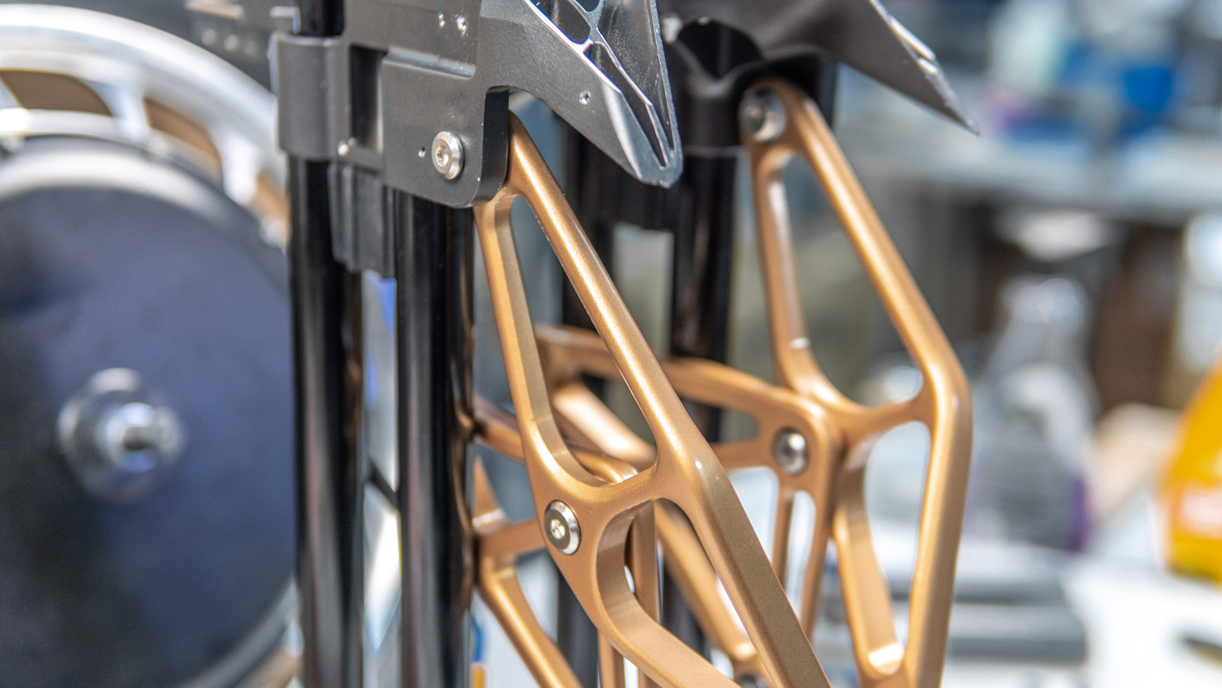
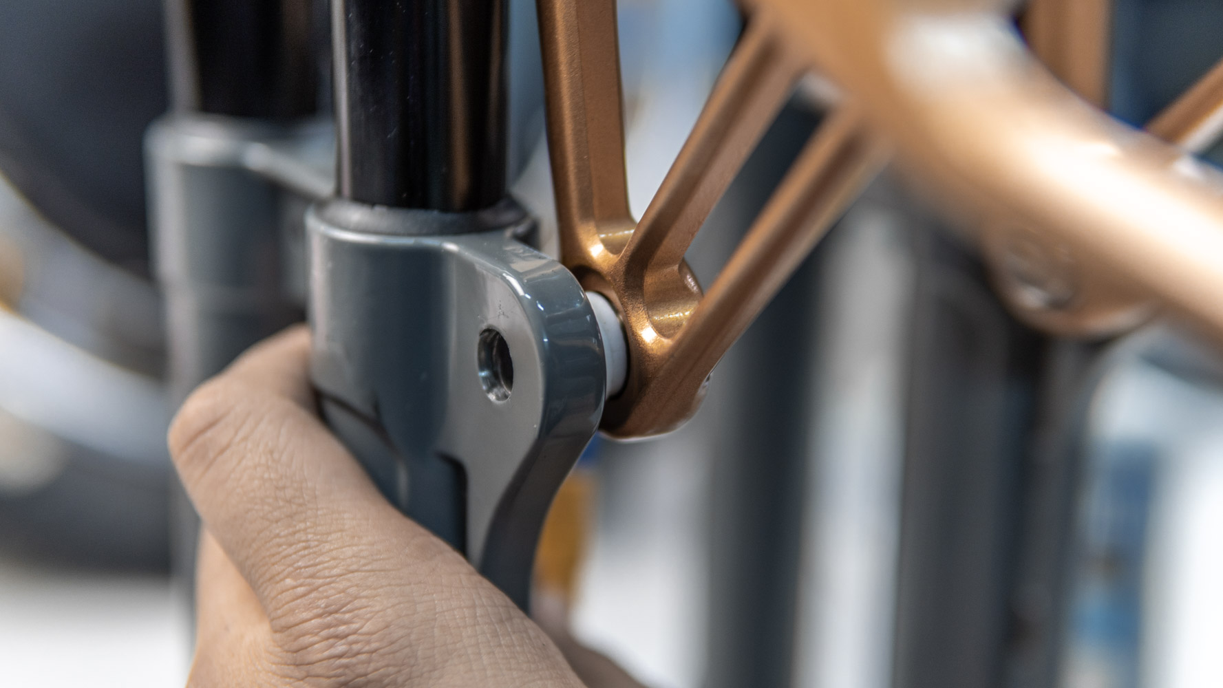
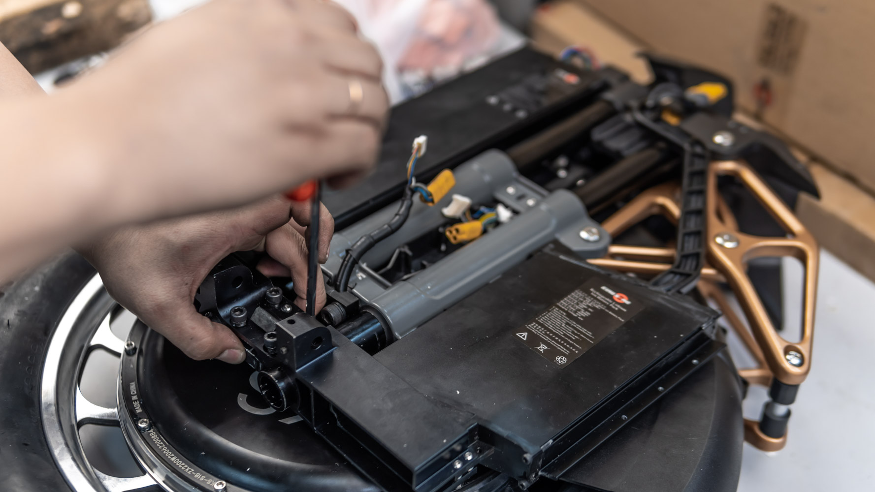
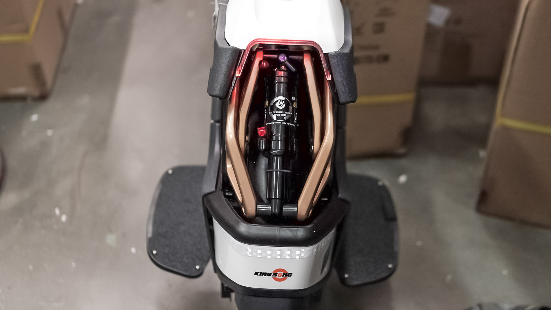
And now we can go on to disassemble the suspension. First we unscrew the axles of the shock absorber.
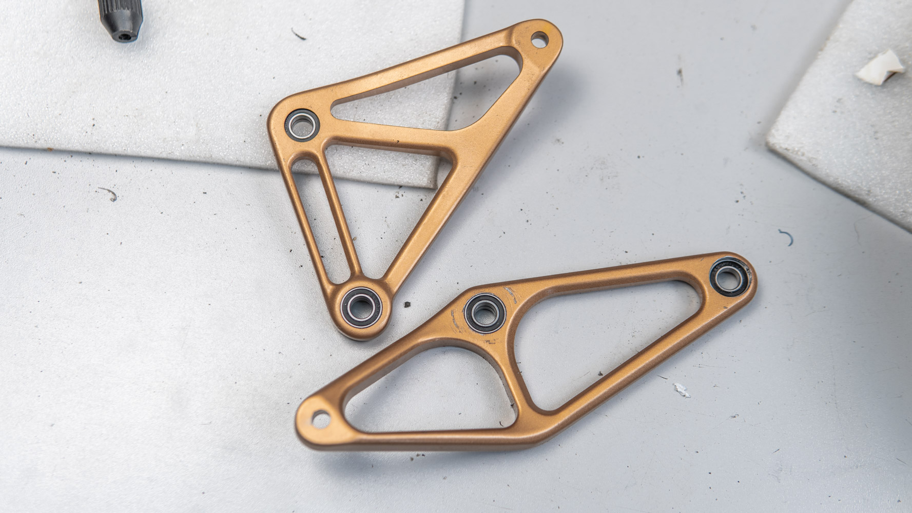
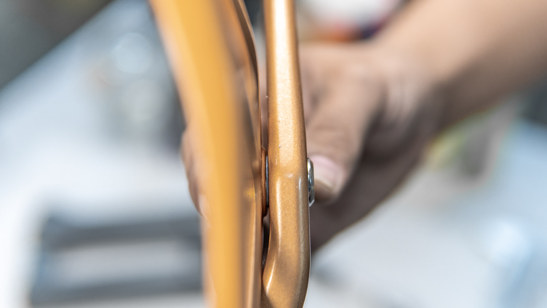
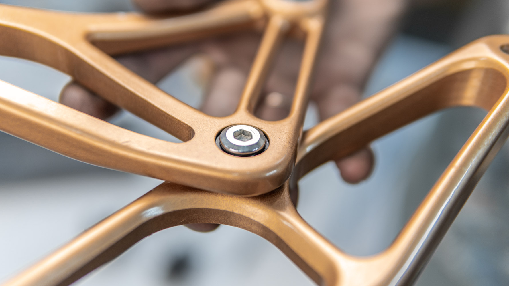
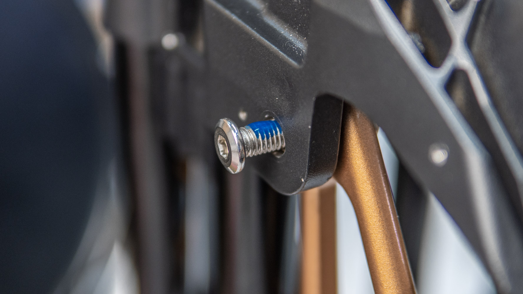
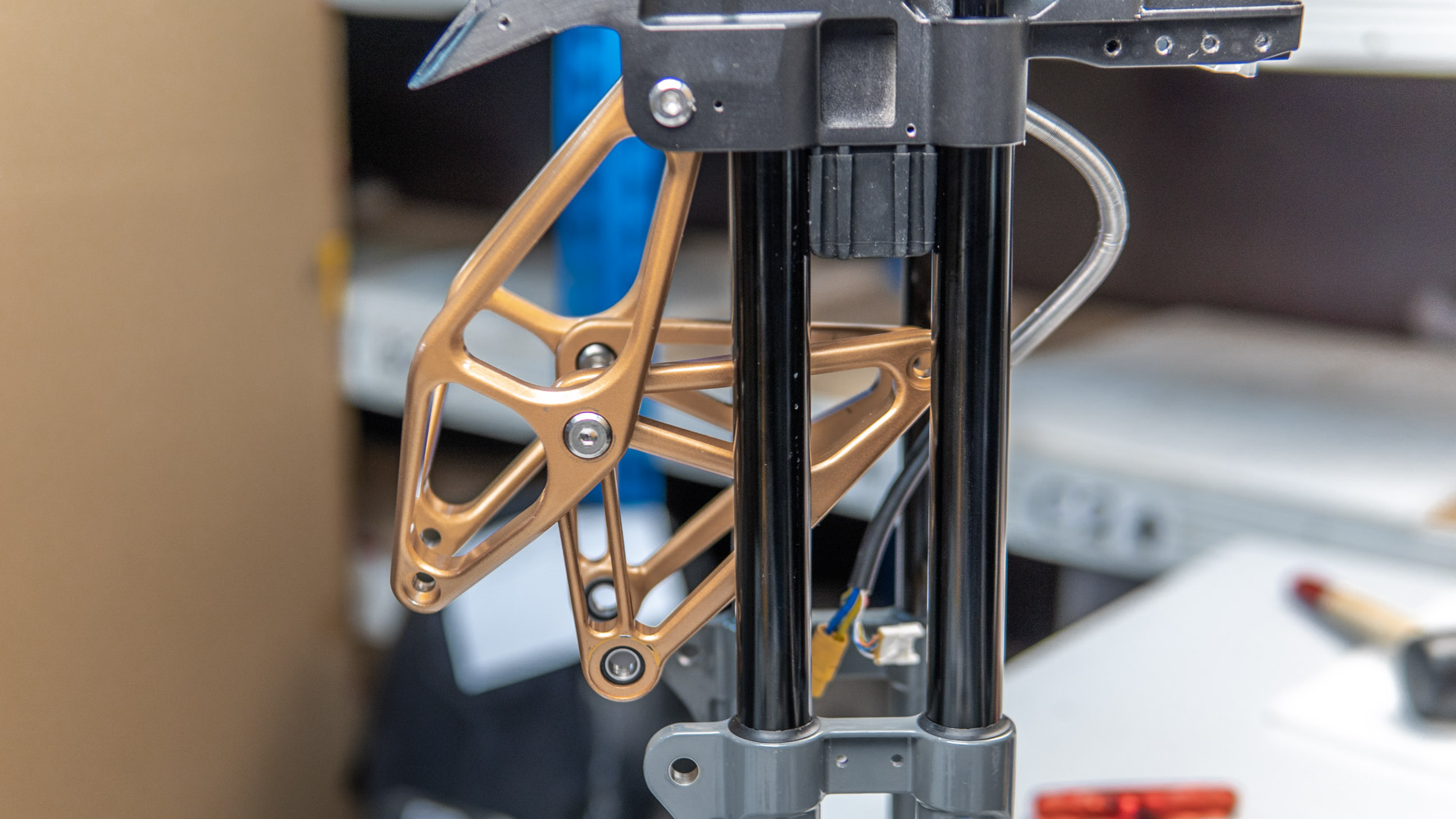
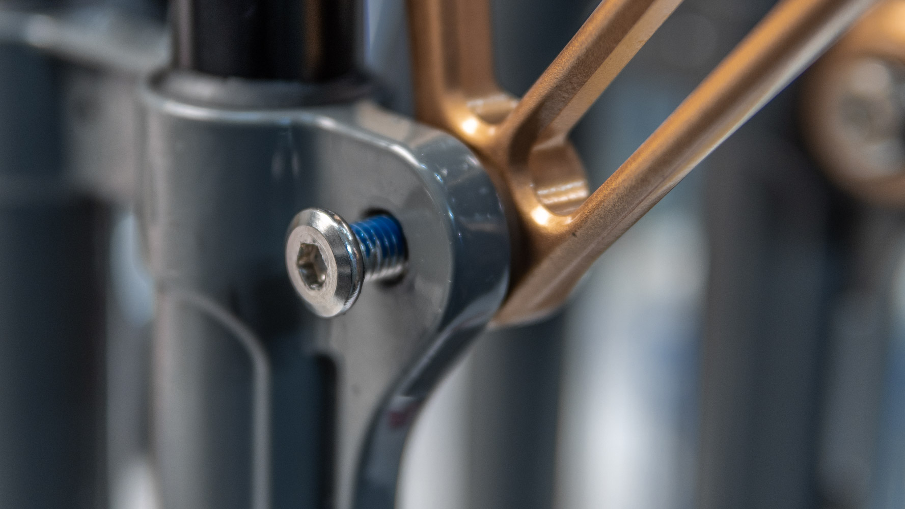
Very carefully undo the screws securing the links (golden frames). The metal is soft, so you might tear down the slots.
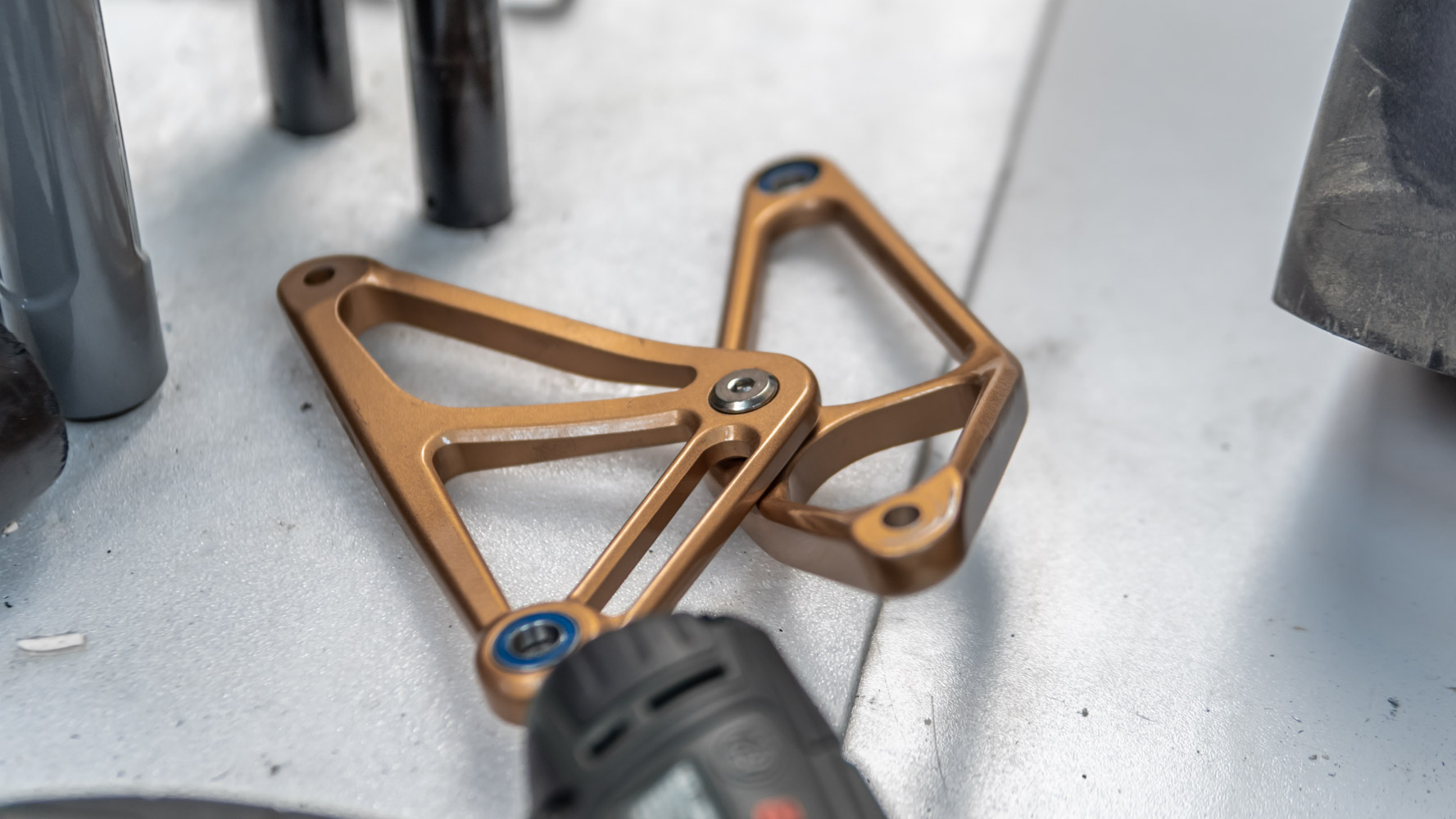
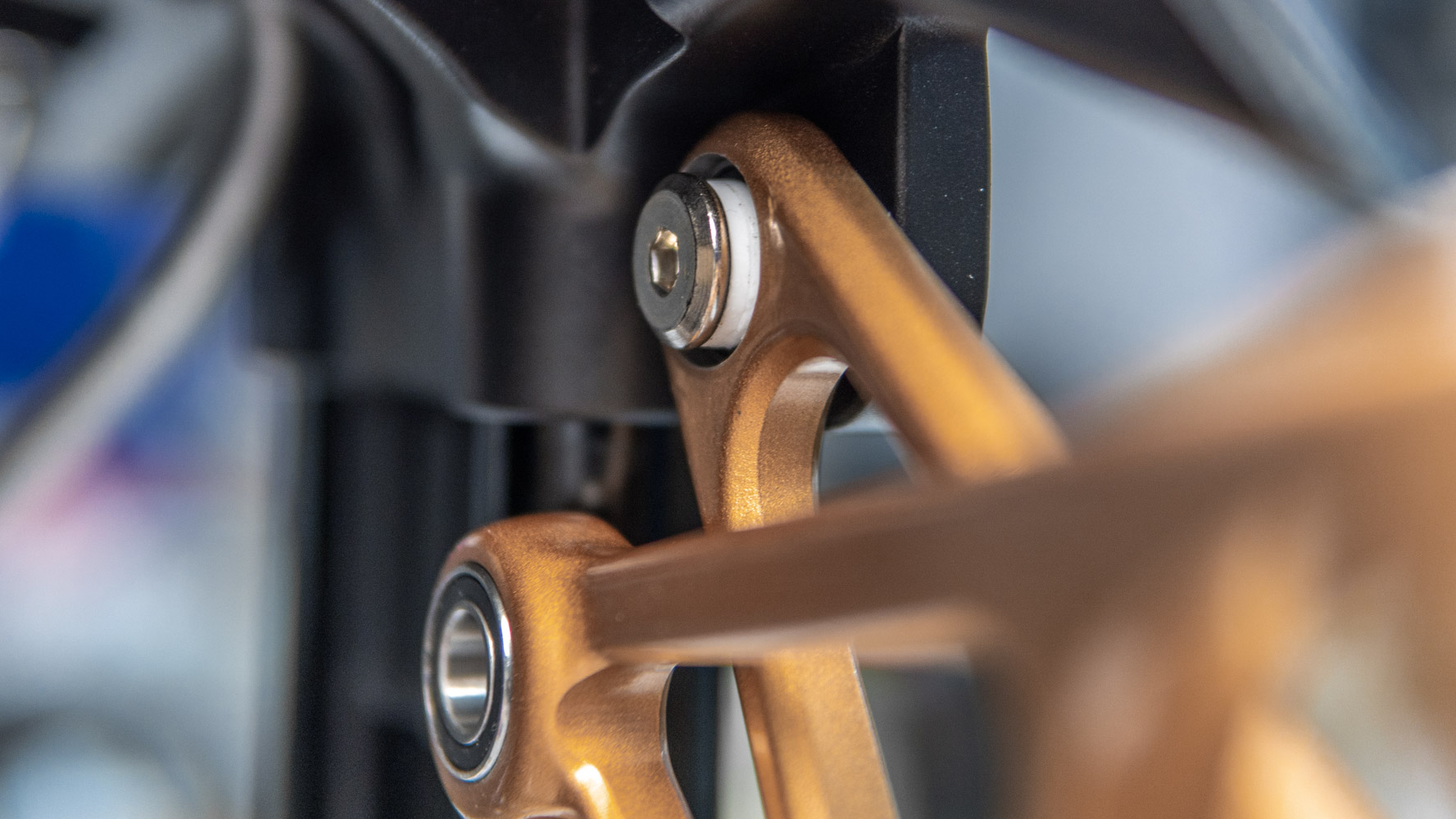
Remove two pairs of links. And we also uncouple them to release all the bearings.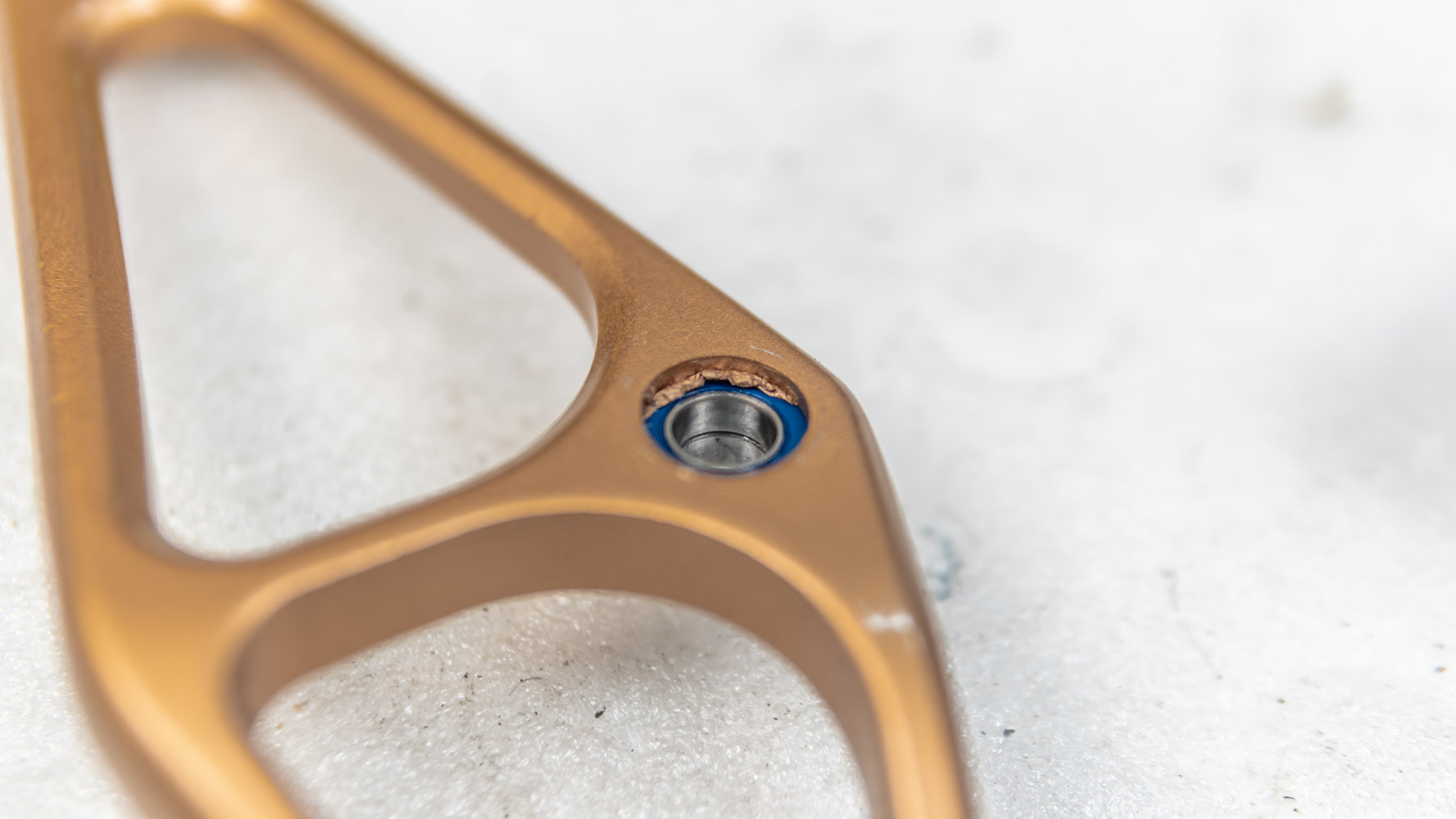
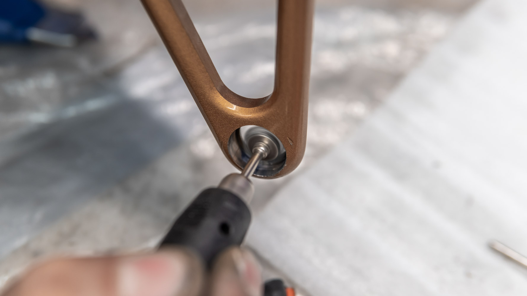
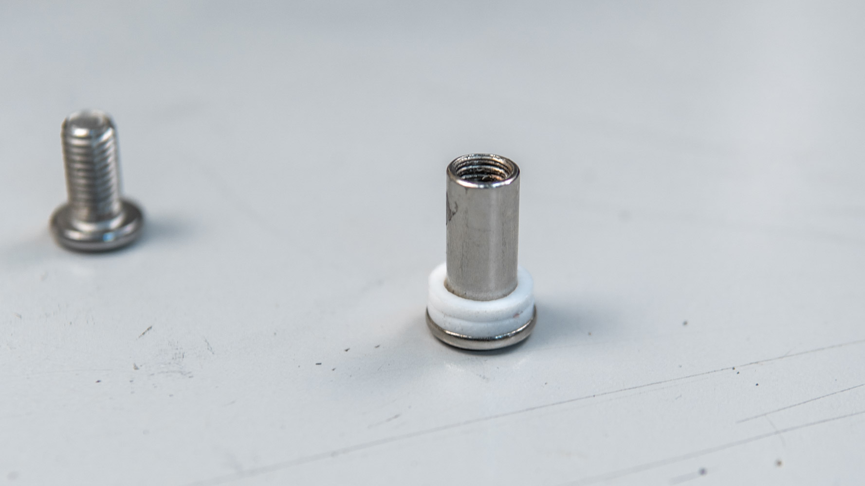
Then we squeeze out the bearings. A screw with a head slightly wider than 10mm will do the trick. After they were squeezed out the bearings are considered damaged and shall be replaced with new ones.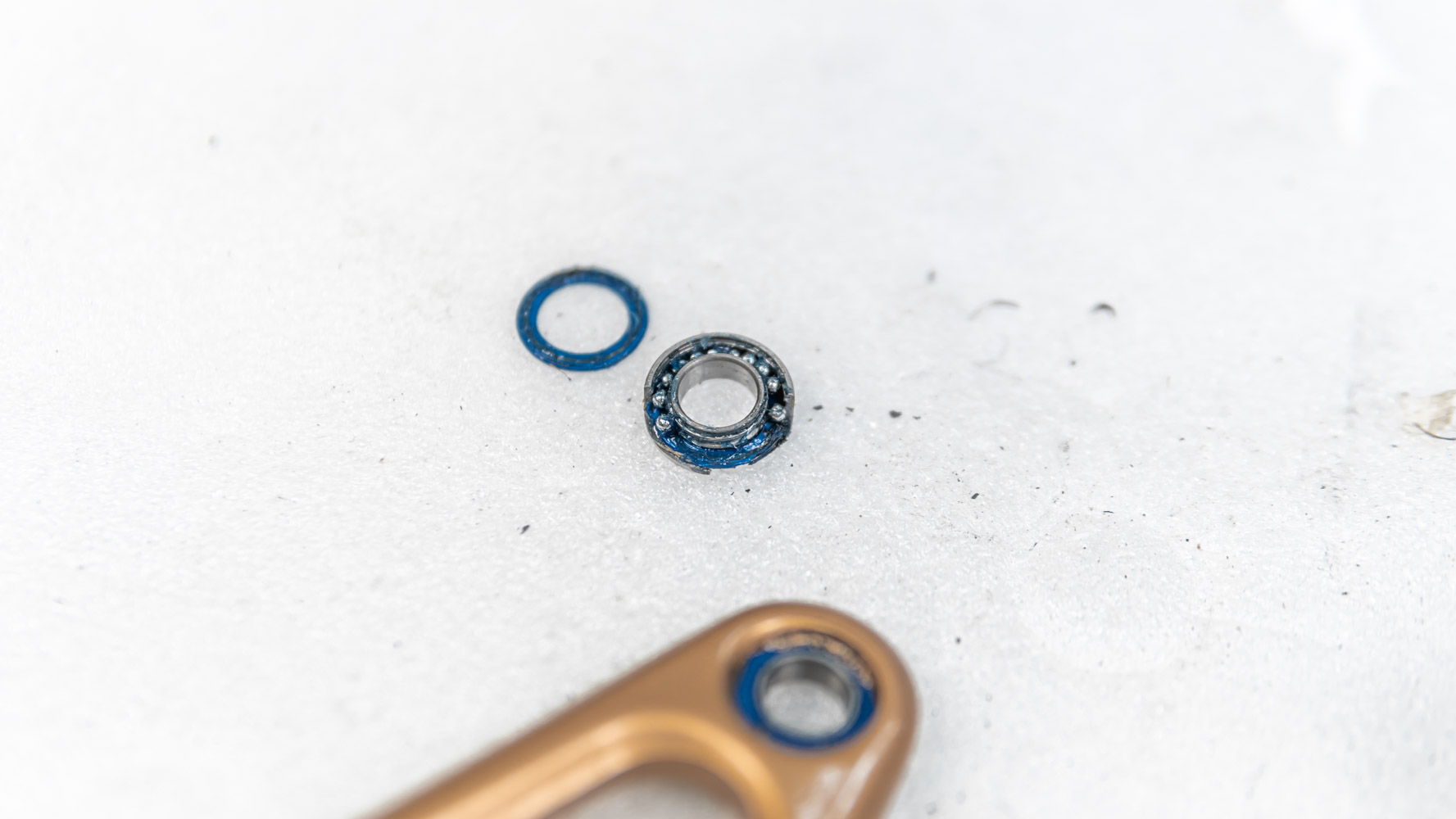
Some bearings break during the process.
The seats should be cleaned.
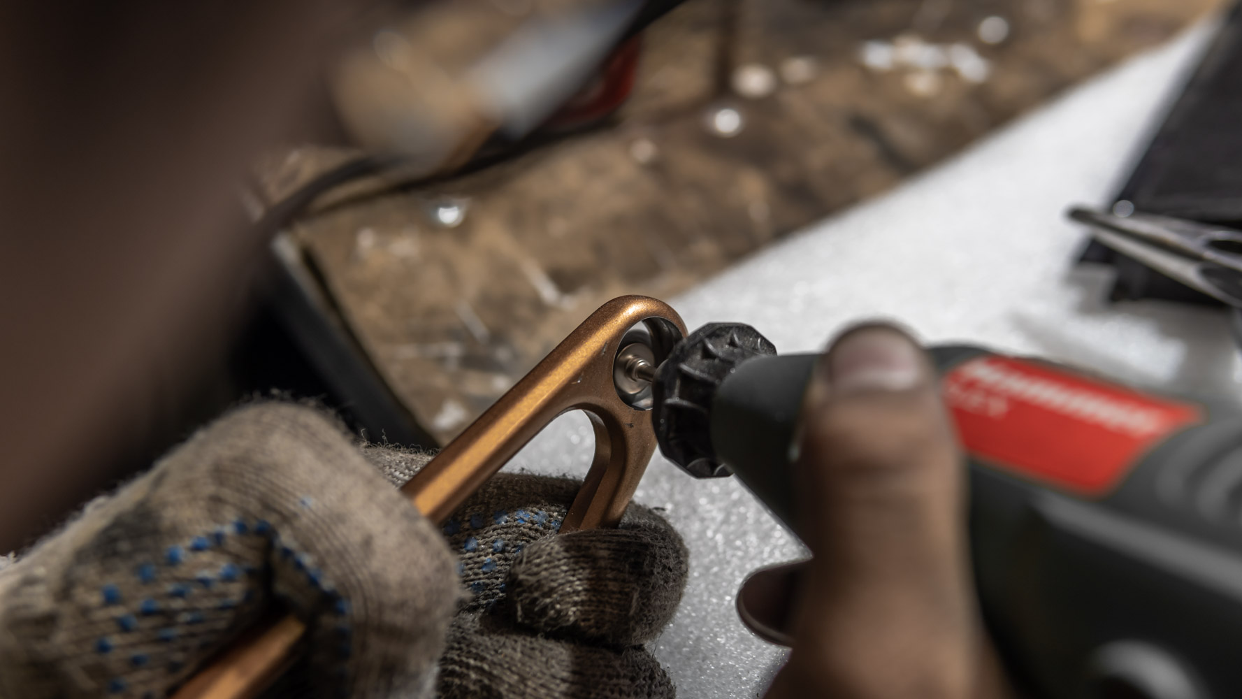
You can use an electric engraver complete with different nozzles. Or you can take a knife, cut through the metal runs and strip them with a screwdriver.
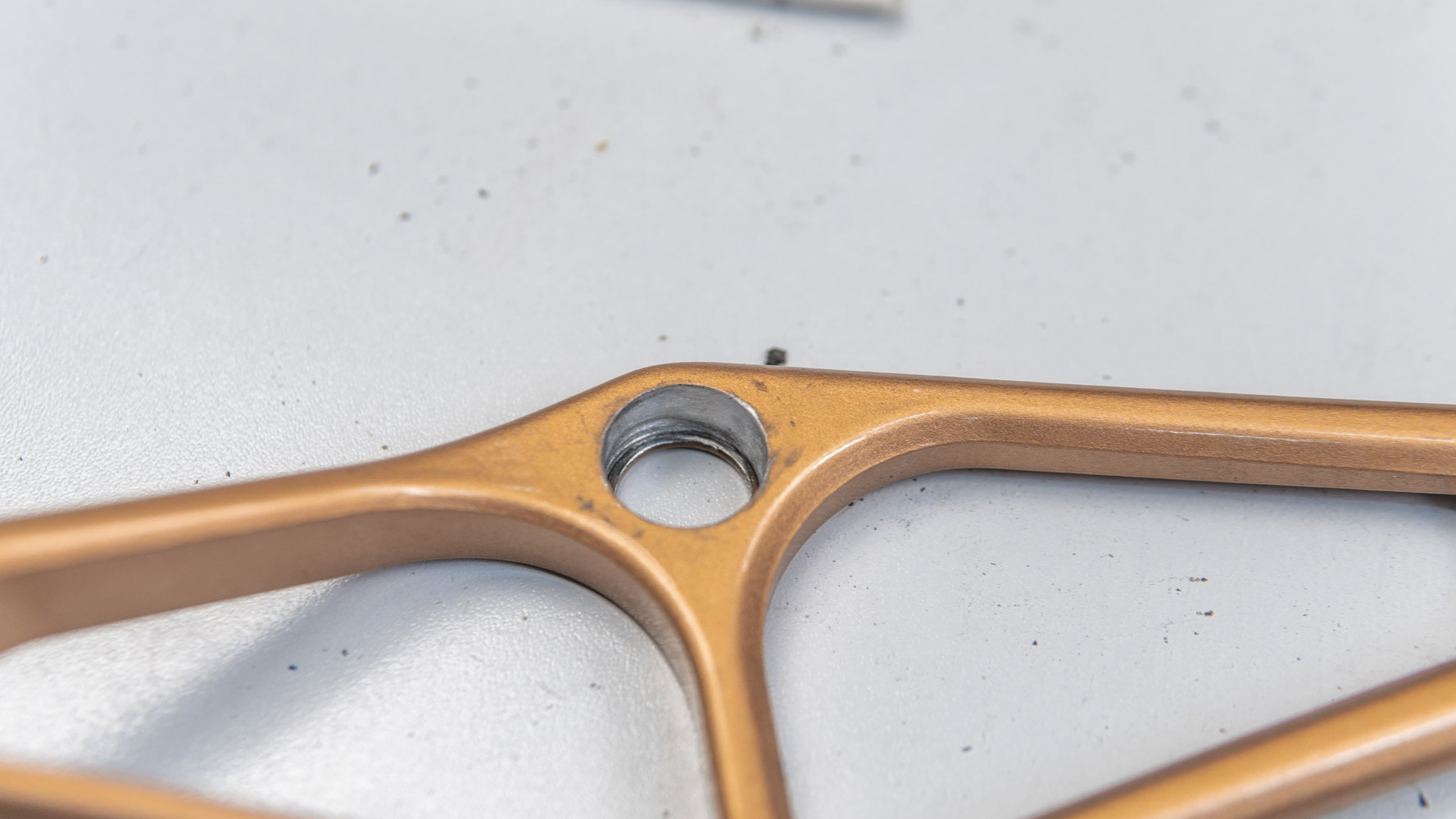
It’ both labor- and time-consuming. After removing the aluminum and paint runs, it is necessary to sand the seating hole to make it smoother and remove the paint. The central holes should be sanded so that the new bearings are not pinched when they rotate.
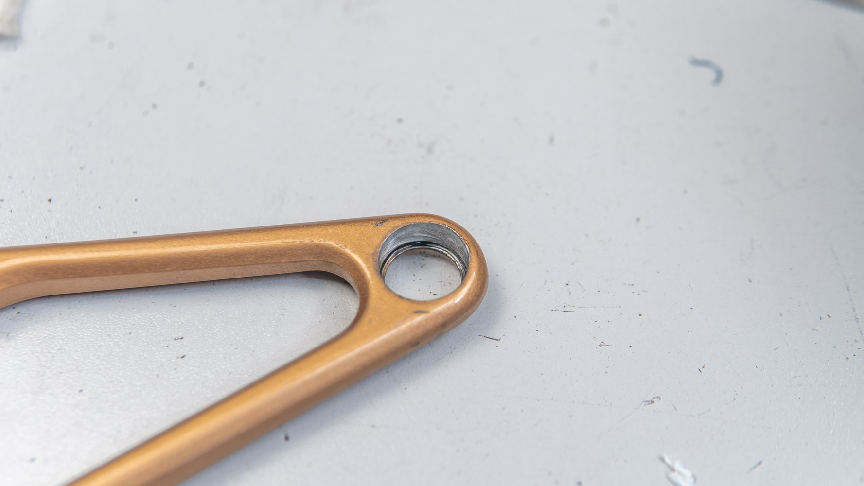
The seat at the edge of the link should not be sanded too hard, otherwise the bearings will not be properly press-fit and will fall out.
We install in new bearings in the seats. We use 19x10x5 bearings. (Types 61800 2RS, or 6800 2RS, or 6800 VRS). I found the Craft bearings here. We need 14 bearings, the load on them is not significant, so I don’t think that you need some expensive and branded bearings.
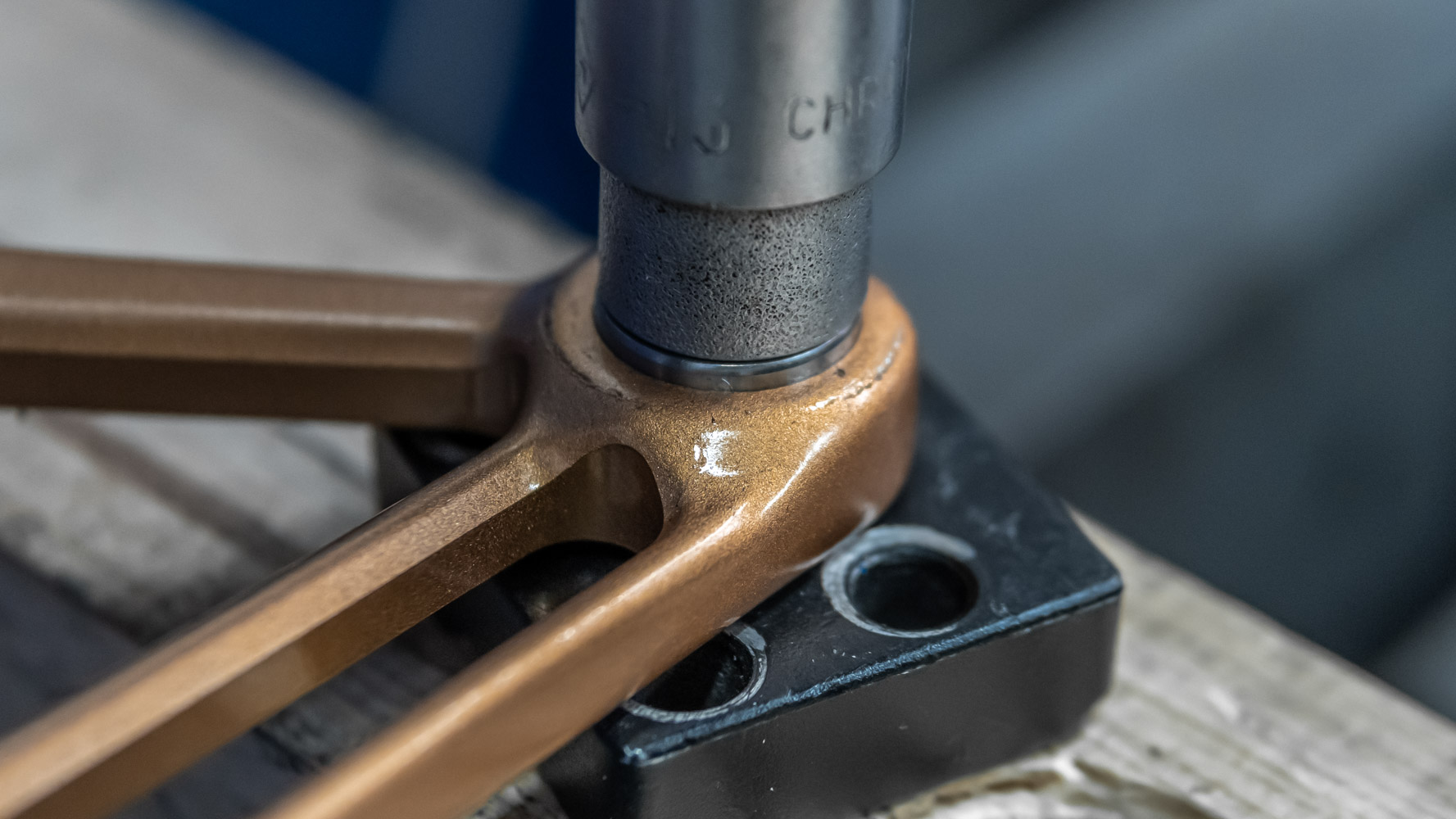
The bearings were press-fit using a homemade press based on a hydraulic jack, a metal platform and a socket of suitable size(19mm). This is very important, because the bearing must be press-fit precisely along the outer race, without creating pressure on the inner race. Otherwise, the bearing will be damaged and you will have to replace it. A long bolt or stud with two nuts and a set of washers of different diameters and sizes can be used instead of a jack. The pressing force shall not be too high, otherwise the bearings will wedge up. If the bearings do not move smoothly, you will need to sand the seating hole a little more.
By the way, I recommend treating it with neutral grease (silicone grease is the best choice) so that the bearing wouldn’t eventually turn sour in the link. Steel paired with aluminum often causes such effect.
After press-fitting of each of bearings, I recommend that you check how the links swing on them. You need 14 pcs., but I advise to buy 20 bearings in case some of them get damaged during press-fitting. It is not good to put excessive pressure on the bearings, since you squeeze them out over the inner ring, which creates excessive pressure, distortion and pinched balls. Such bearings will be then unfit.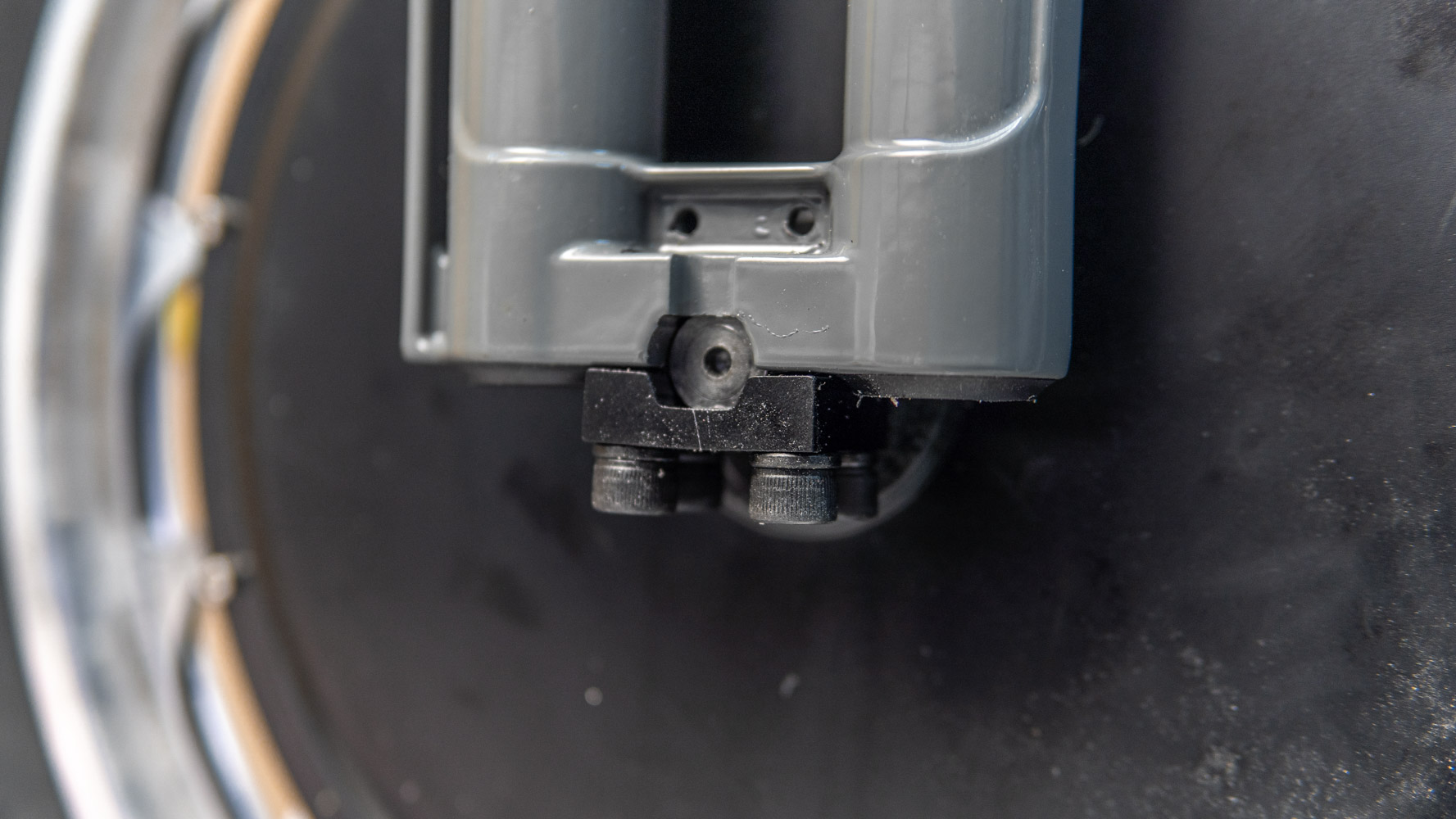
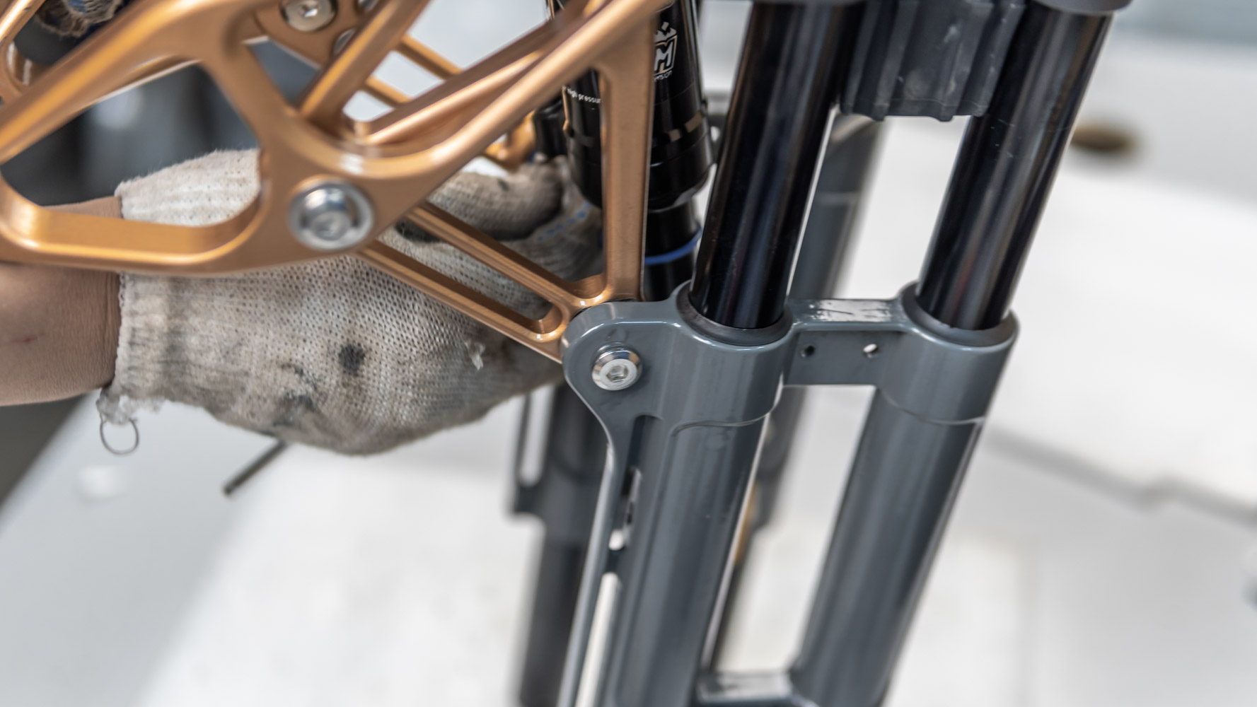
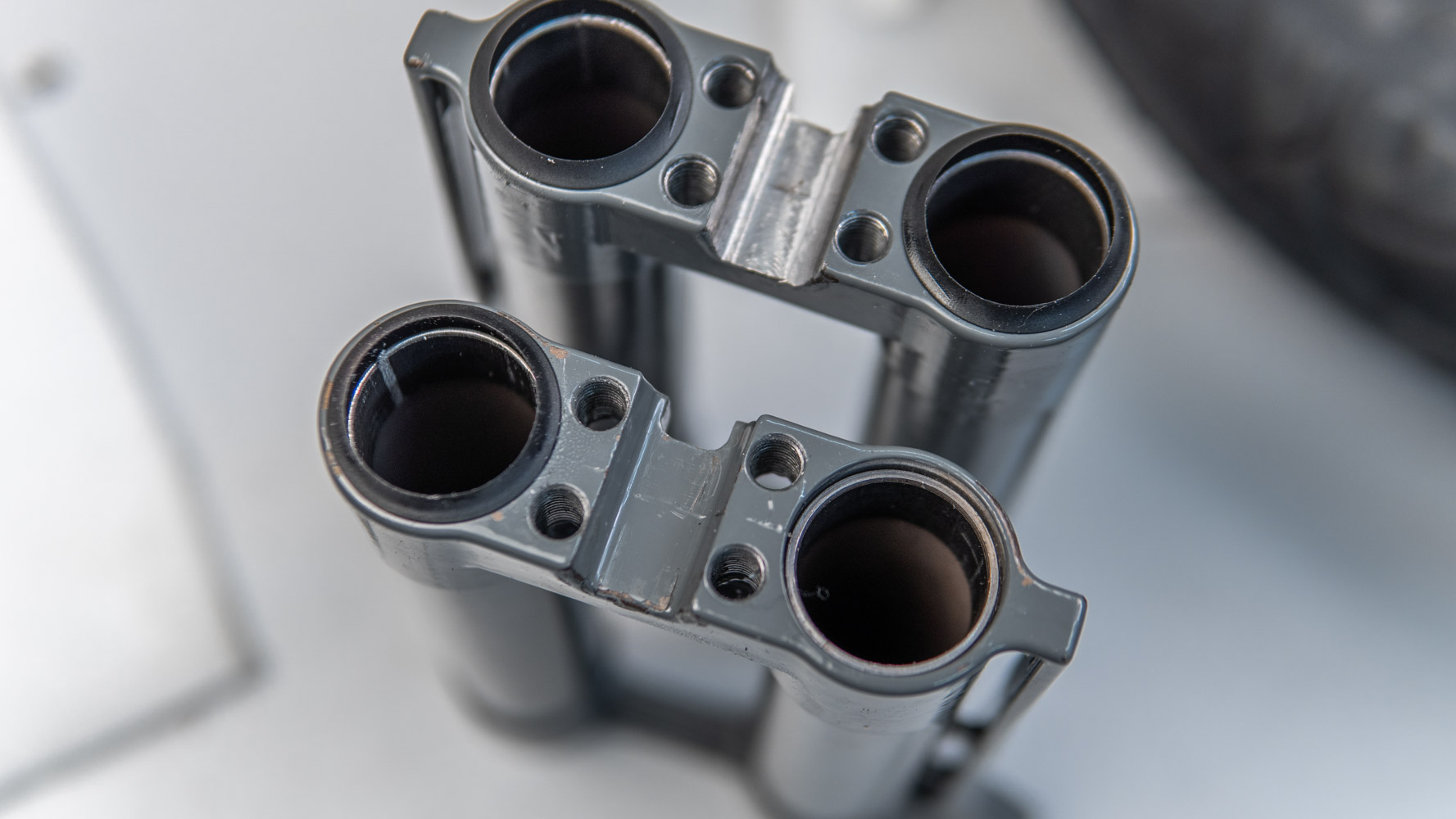
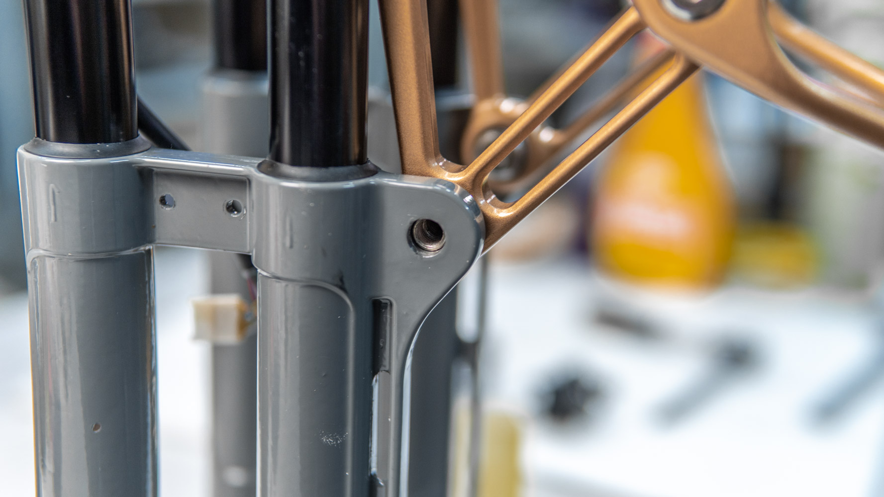
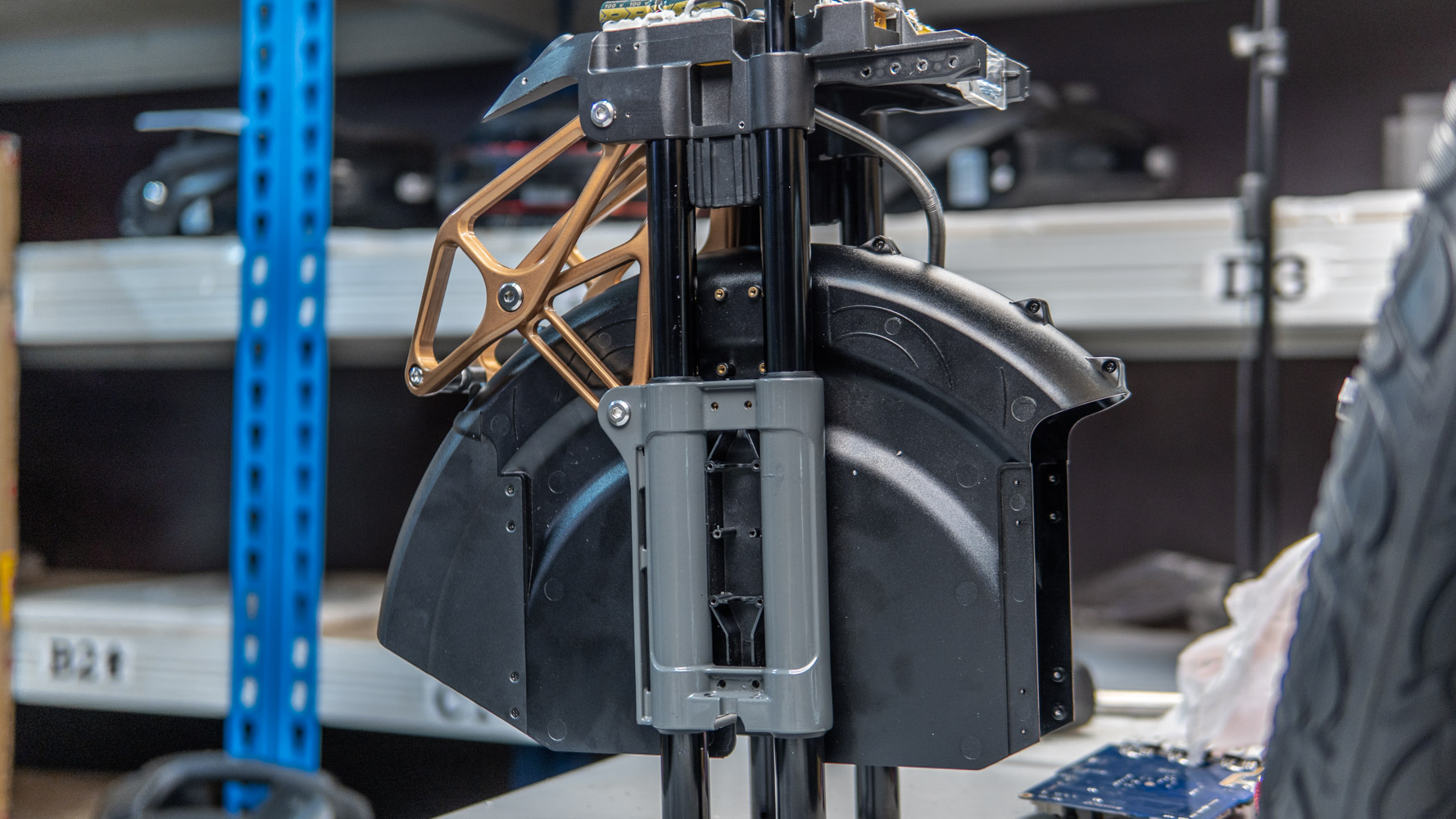
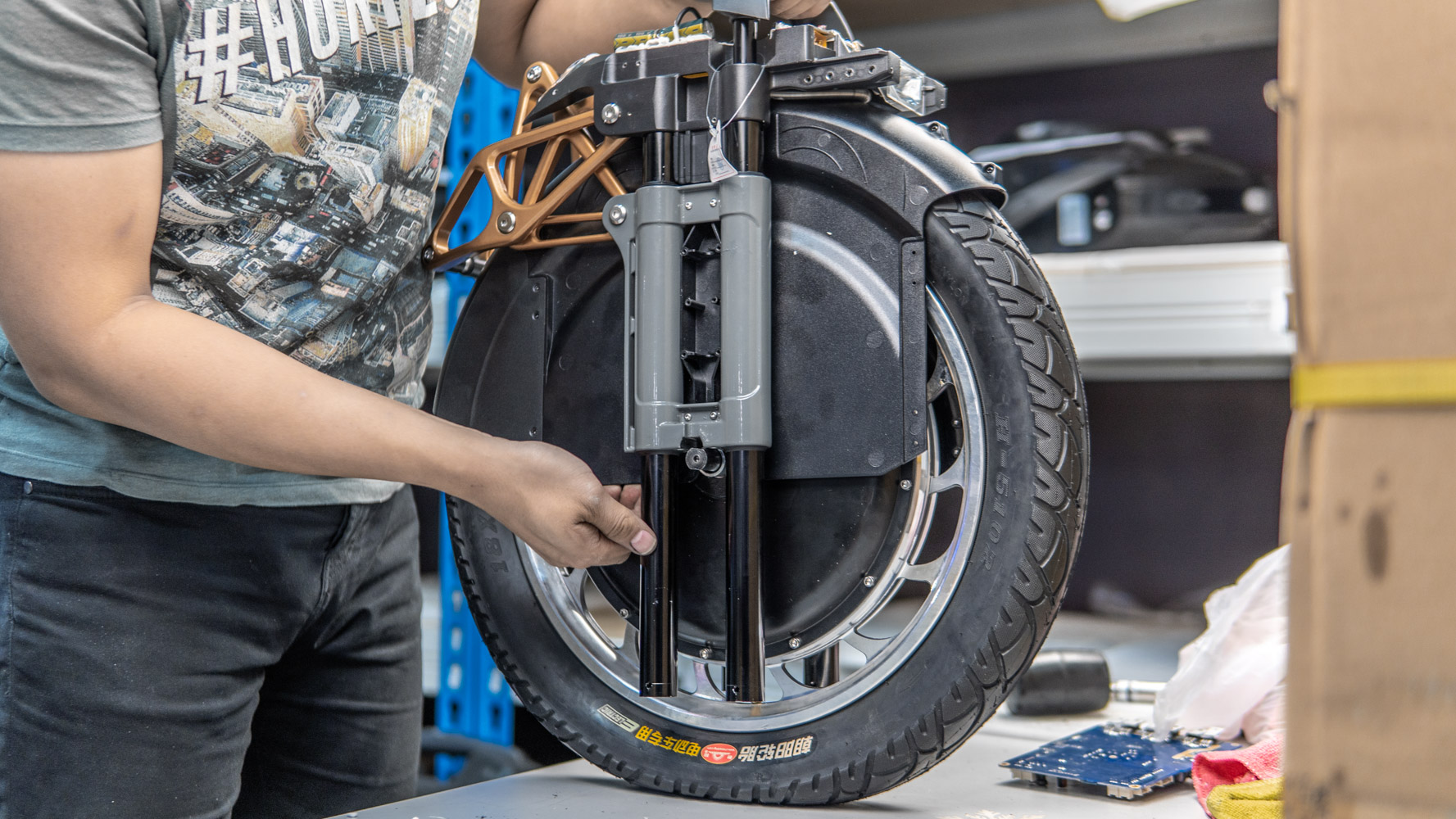
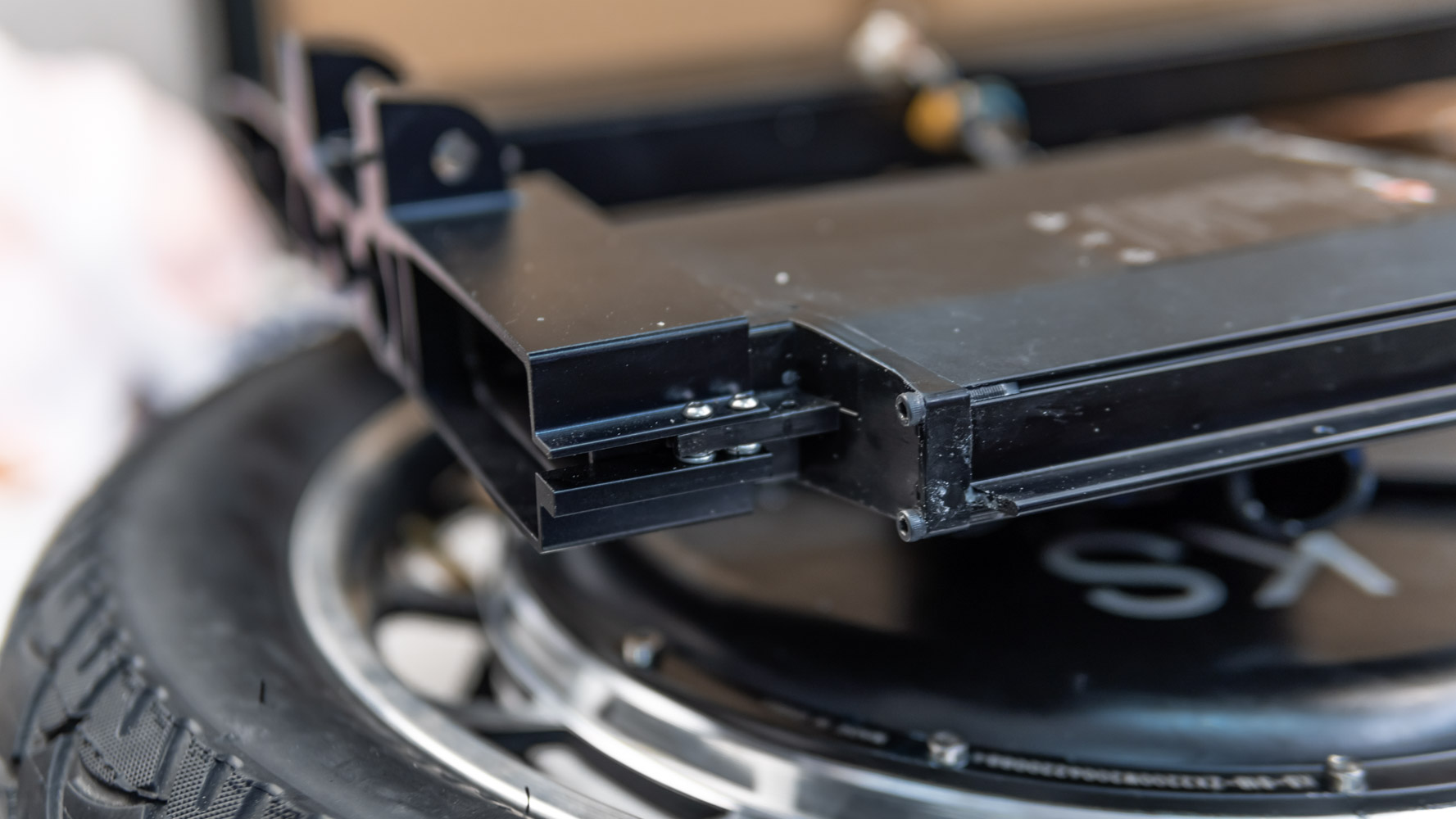
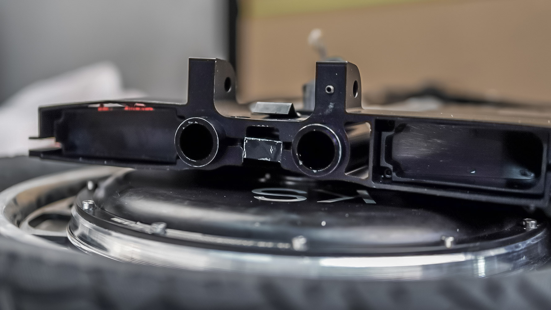
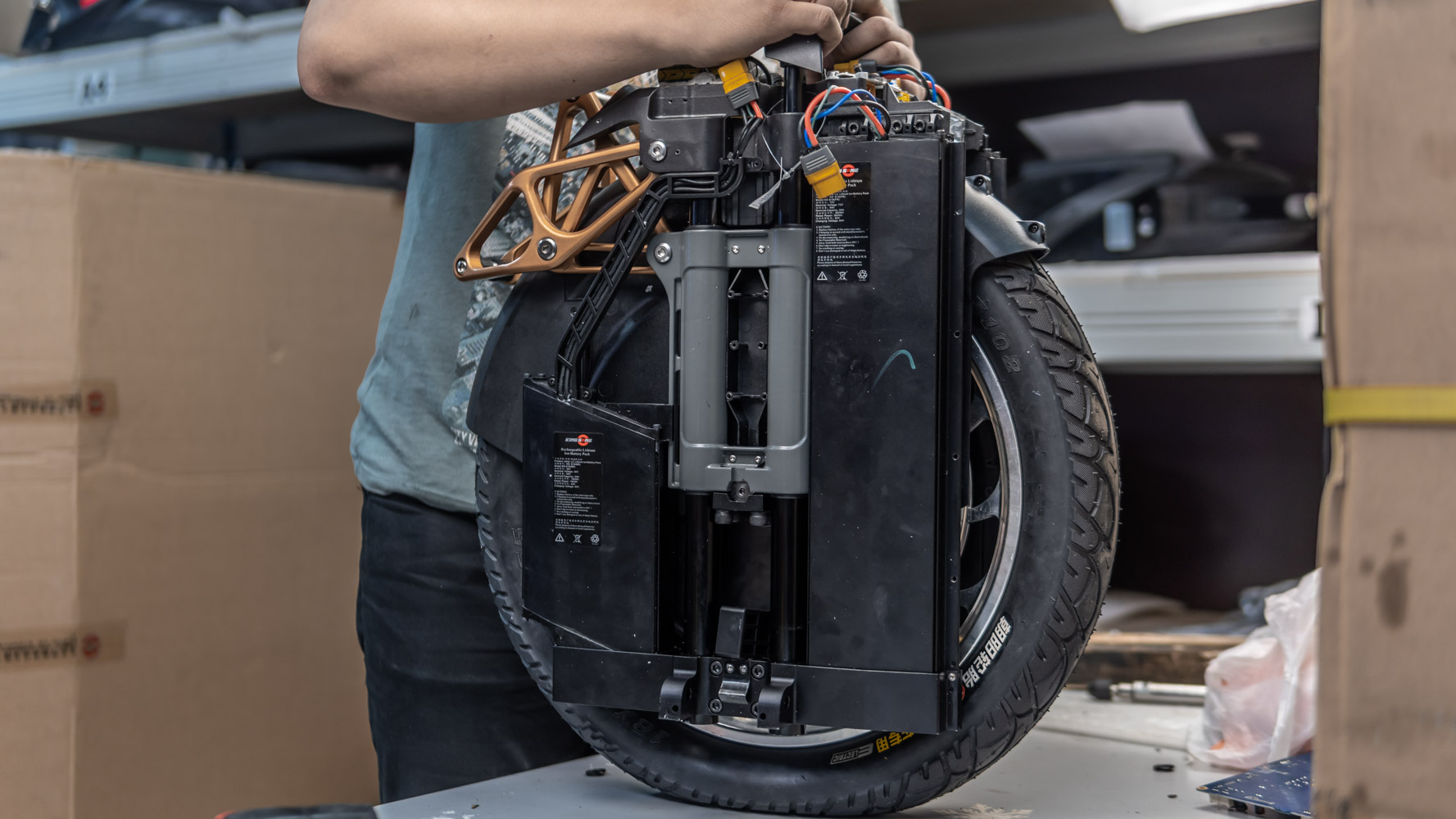
The next step is to check the axle and sliders (grey iron parts of the suspension, otherwise “pants”). First, make sure that your axle has strictly parallel mounting cuts and does not narrow to the edge. Then fix the sliders tightly on the axles as usual.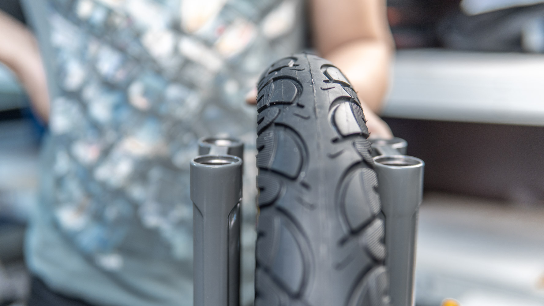
Make sure that the sliders stand exactly parallel.

Check how the upper base pipes (with the controller, called also “legs”) move in the sliders.
Pipes should move well and smoothly. Watch the gaps. If there are problems with movement, then check the deviation. Find out which slider deviates and at what angle.
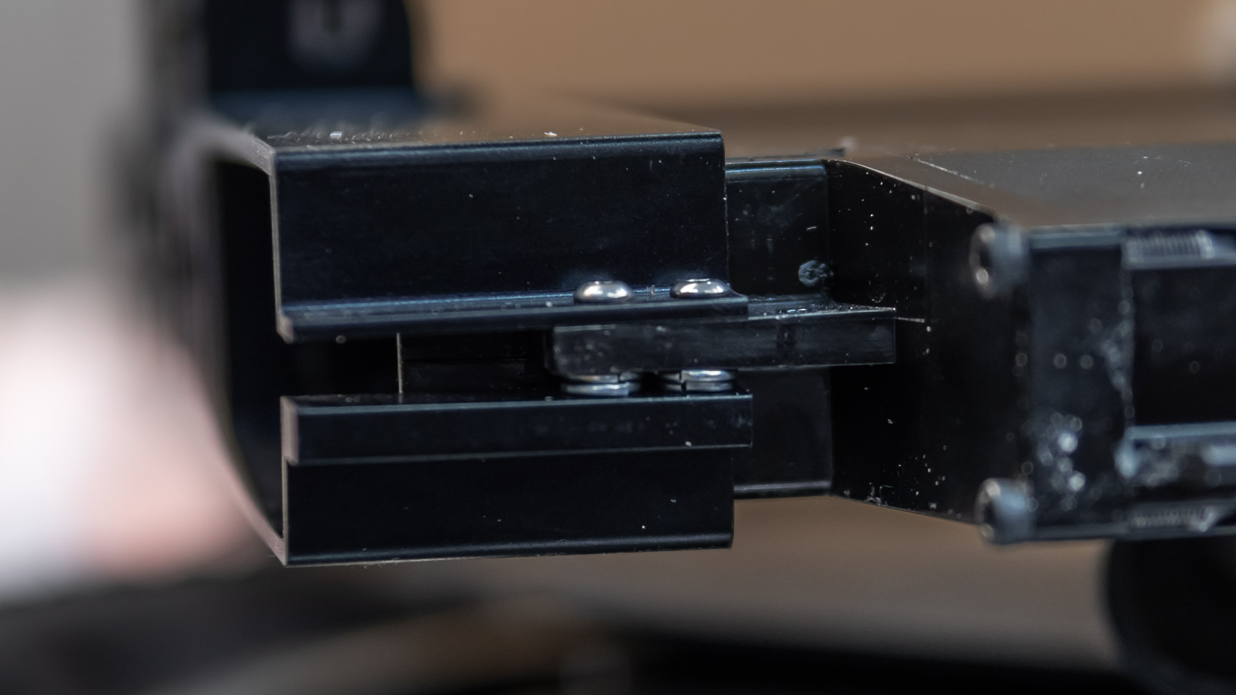
After that you should carefully widen the groove to fit the axles on the slider. Some sliders are supplied with a groove. Some are not. It is also possible that there will be a metal plate between the axles and the groove of the slider. Moving forward a little, it helps to align the engine in the arch so that it stands upward.
After widening, we fix the slider again on the axles with inserted pipes and, by tightening 4 screws each at 1/6 turn, control the vertical position of the slider at all times while moving the pipes so that they are not pinched. You may need several goes at this. The milling machine is not at everyone’s fingertips, so you need a good file and vice clamps, so that the pipes move in the right plane as closely as possible. Otherwise, you may easily damage the part. Fitting of sliders to the axles is also a very labour- and time-consuming process. But not all wheels require such fitting. Sometimes, sliders from the factory are quite well fitted.
On the photo above note that when clamping the axles the lower finger can also clamp the plastic axle boots. If they are squeezed, they start to press on the pipes and don’t let them move either. These boots need to be carefully worked on with a needle file to create small indentations so that the finger no longer presses on the boots.
The next step is to install links. You will need bushings to assemble everything correctly. It would be best to make them out of nylon. But, unfortunately, the details of different wheels significantly very in sizes and it will be very difficult to pick the required size. So I decided to just buy a sheet of fluoroplastic and with quite simple set of punches make the necessary washers that would replace the bushings. The washers must be as thin as possible to be able to connect each pair of links. You can take a sheet of fluoroplastic and flatten it with a heated iron or press to make the washers. It is better to stain the washer first, and then flatten it. It will be easier and more efficient. Washer size: 14×10. From personal experience, I can say that it is most convenient to work with a 2 mm thick sheet.
Then we install the thin washer between the links. Don’t worry if it turns out not too neat. We just need to separate the outer races of the mating bearings. There will be no significant load on the washer.
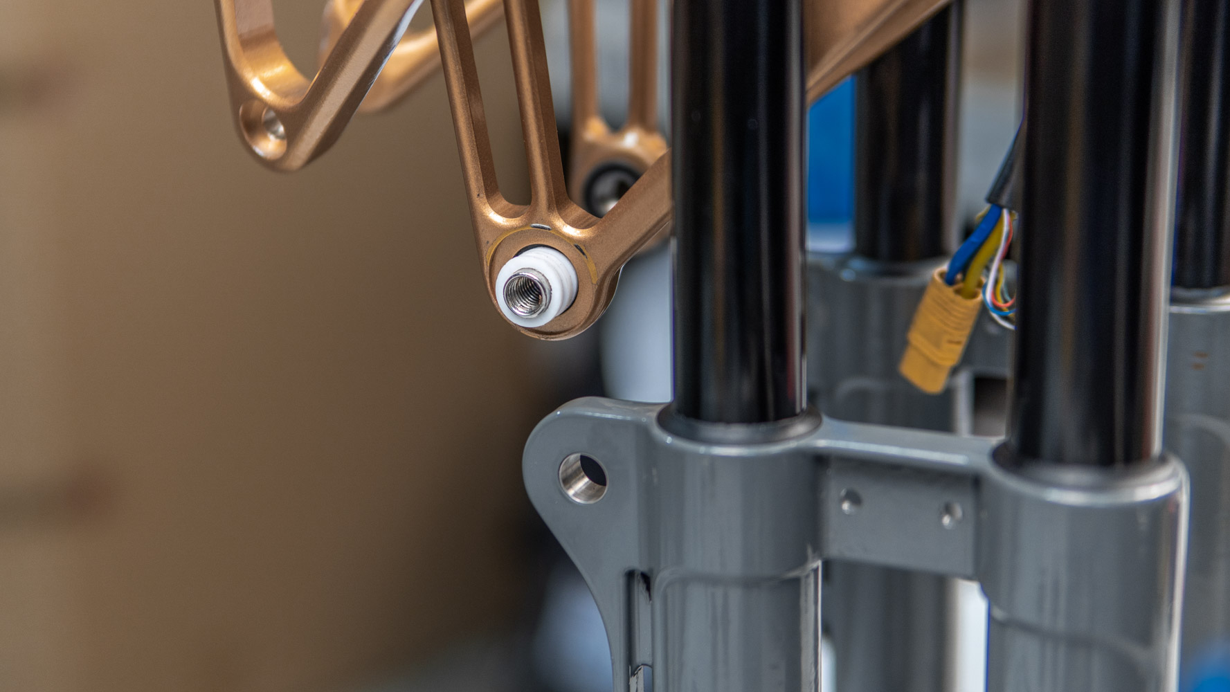
The length of the axles is 22mm, it holds 4 bearings on it, i.e. 20mm plus a flattened washer about 0.2mm thick. We add another 2mm washer so that the details are not slack. Screw in the axle screw (with a drop of threadlocker) until it stops. We check how one link swings on the other.
Now you have to fix the link in the upper base loop (where the controller is). We will need to install 2 washers (4mm) twice here. We take the axles, and string two washers. Then we run the axle through the bearing and add 2 more washers.
And now we insert it into the loop.
Drop a dab of the threadlocker on the screw and screw it until it stops.
But here you need to avoid tension and check that the axles do not start to compress our fluoroplastic washers.
We check how our links work. They should move smoothly.
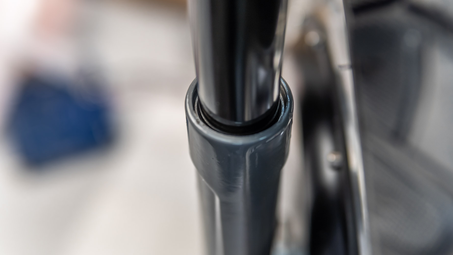
Before you proceed, carefully wipe and degrease the pipes to keep them clean. Apply a little silicone grease and dry thoroughly with a clean microfiber cloth. This way, we obtain a thin almost dry layer of lubricant on the pipes so that as little dust as possible adheres to them. Slider sleeves can be additionally sprayed with dry PTFE based lubricant (Teflon grease). Now we put the sliders on the pipes to fix the bottom links.
Again we take the axle and 3 washers to obtain 6mm.
We insert the axles into the bearings of the link, and we string the washers on the other end.
After that we insert it into the loop of the slider.
This is what we get.
Then we fix the screw with the applied threadlocker.
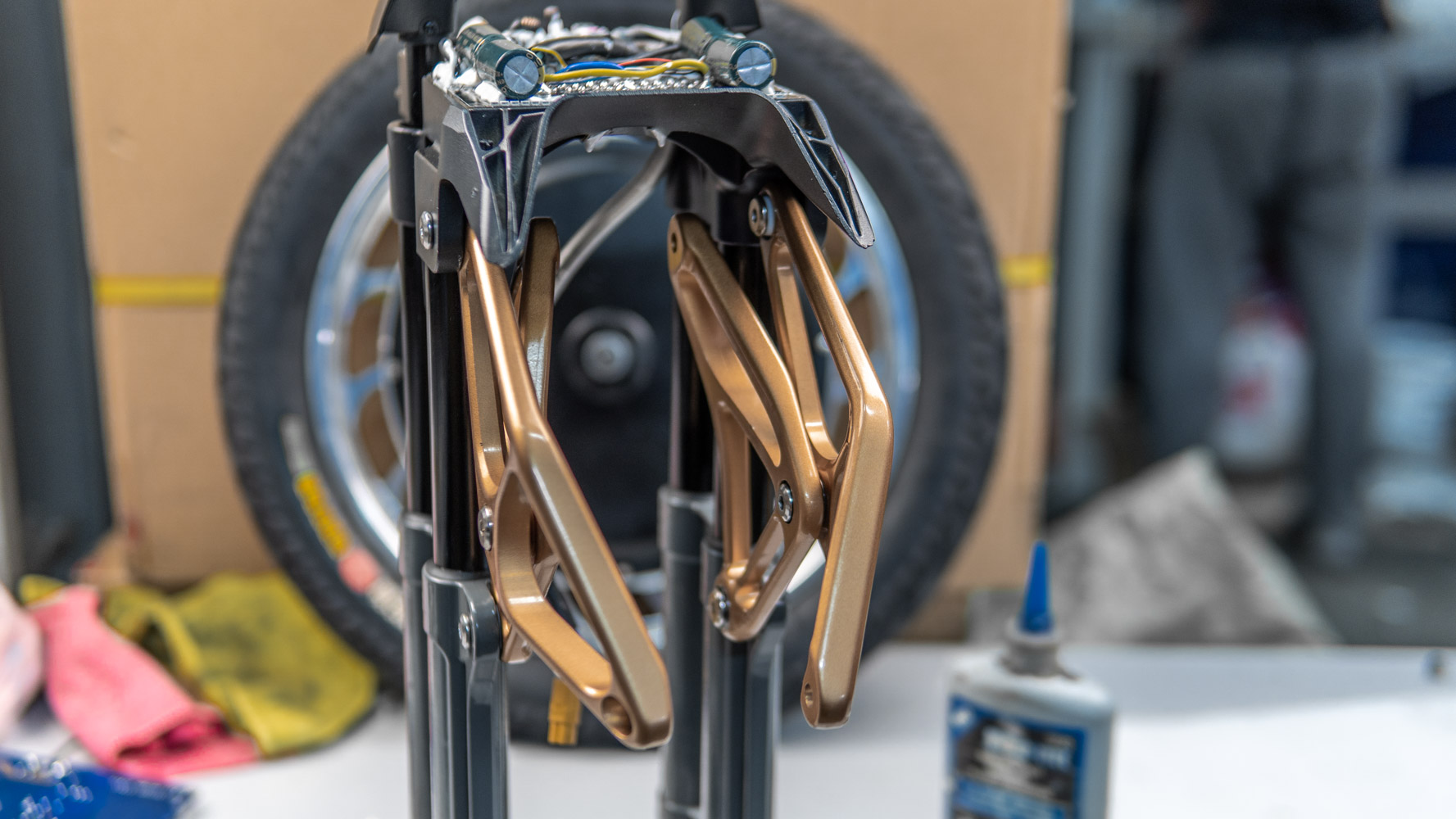
We check the links. Sliders should move smoothly and without resistance. Then we connect the links and the axes from the shock absorber and installed spacer bushings, but we don’t install the shock absorber. We check the movement again.
We put the mud protector back in place.
We put the engine back.
And fix the axles to the sliders. And check again. Sliders should move freely on pipes.
Now, we proceed to the so-called “battery base” (underpants). Here I will allow myself a little distraction.
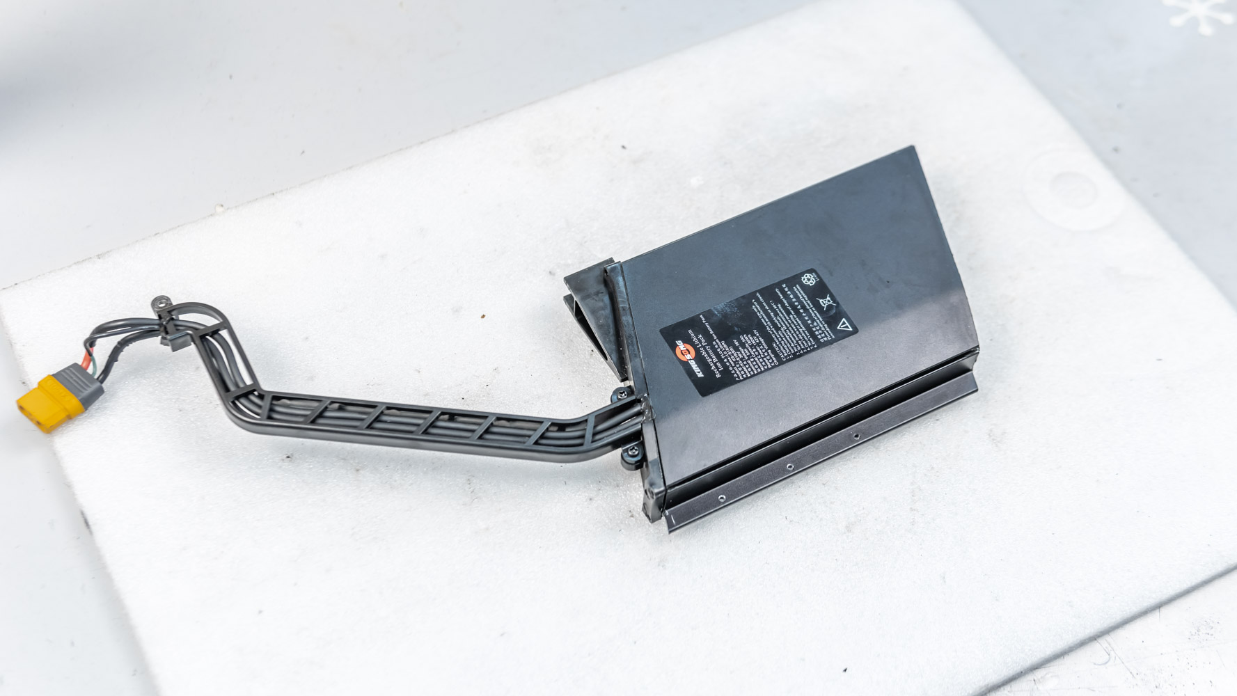
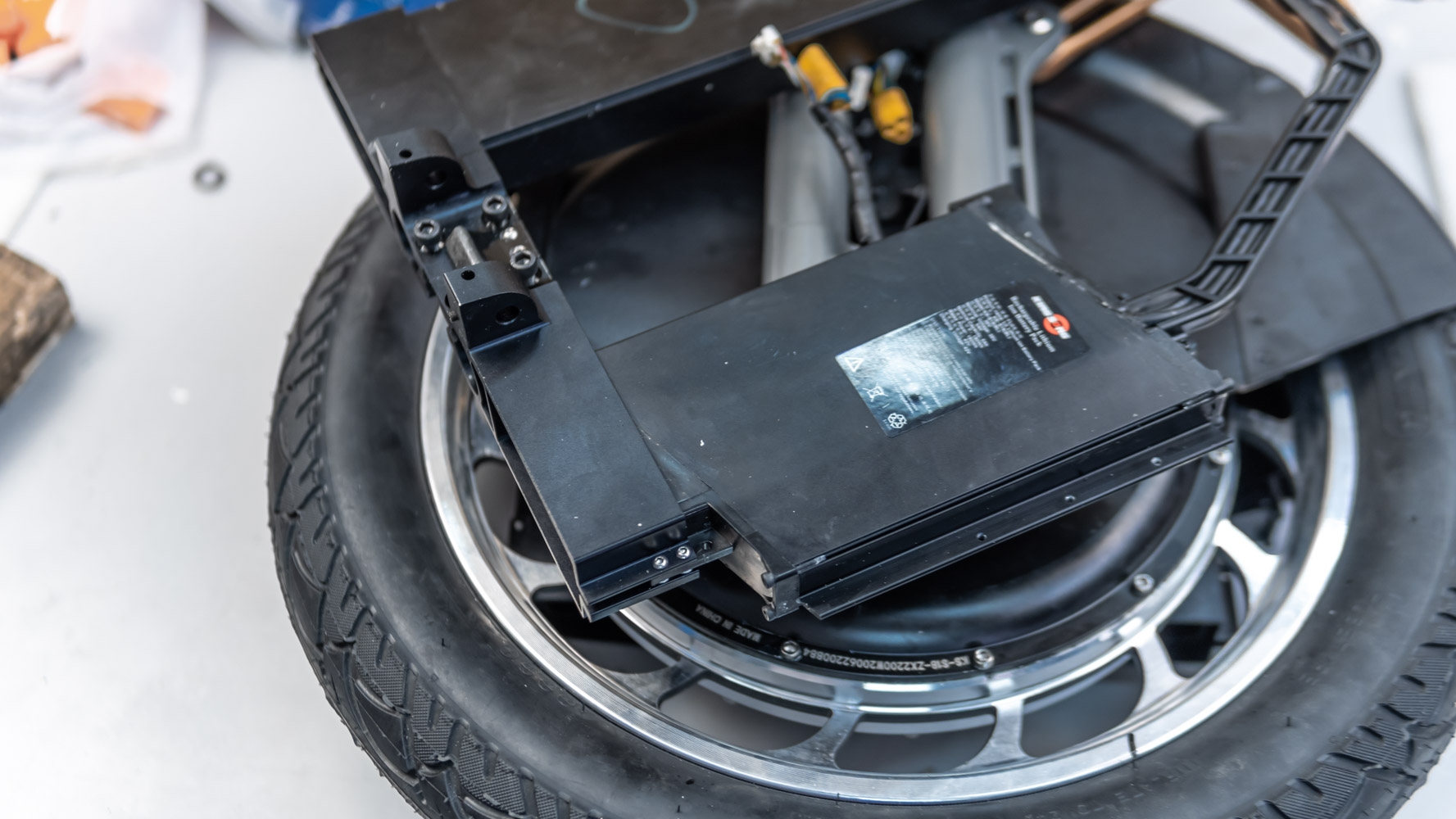
I want to show you how the battery is arranged inside.
The small one first. It consists of 10 cells connected in series. The charging voltage of the unit: 42V (rated voltage 36V).
The unit is placed in an aluminum profile, under the CEM we see a complete BMS unit.

LG M50T cells.
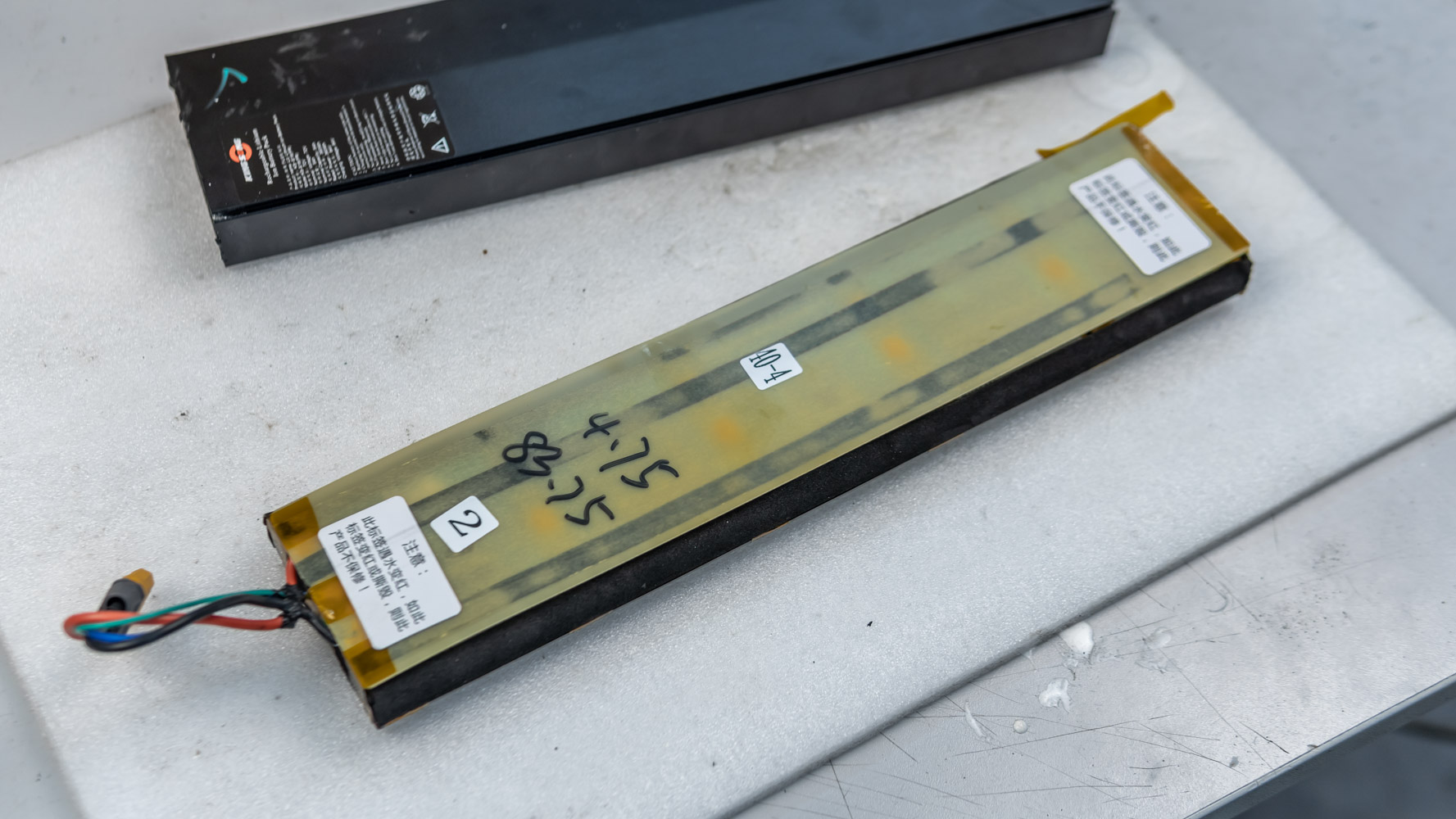
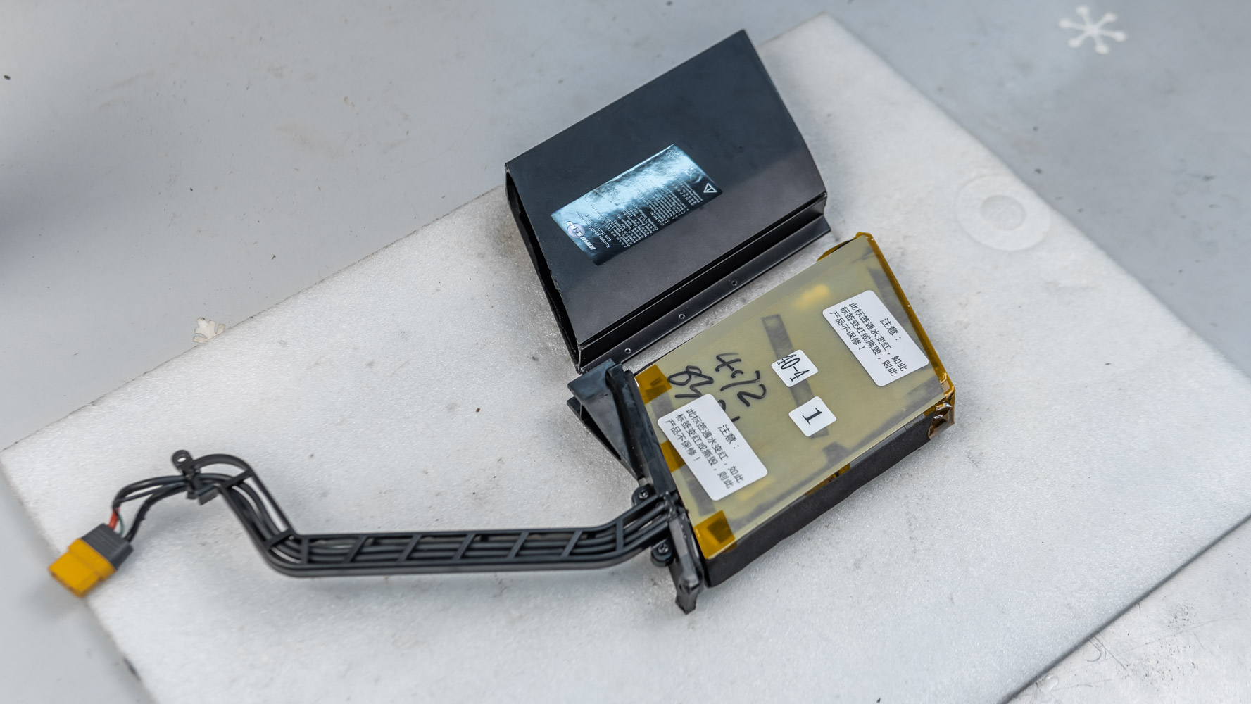
The large unit with charging voltage of 84V.
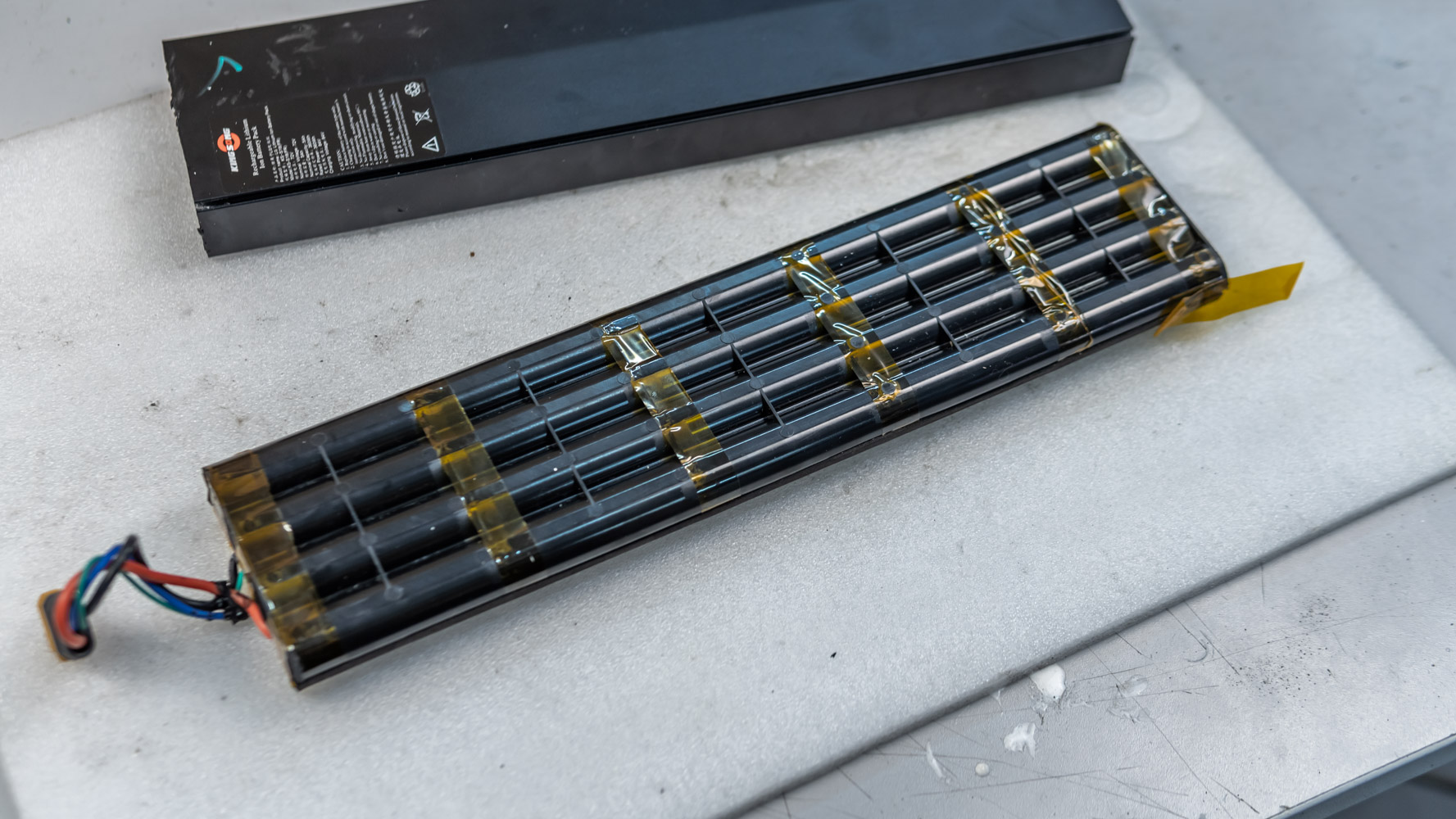
Plastic holder for cells.
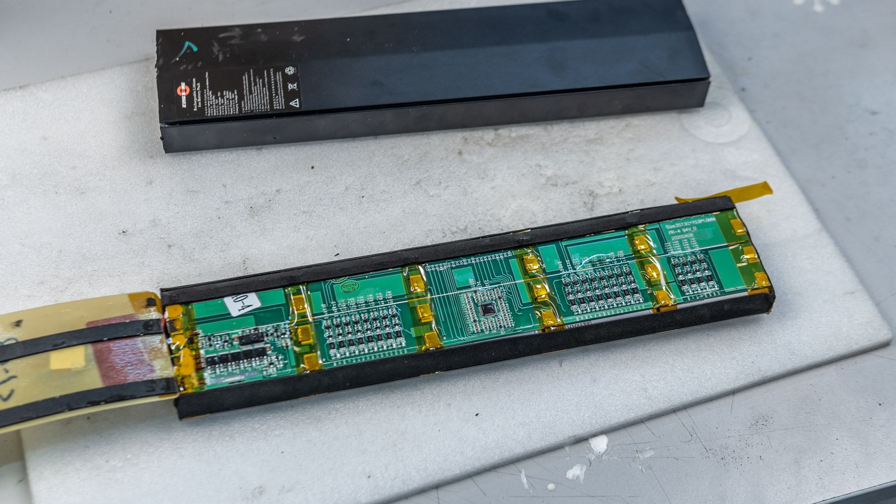
The BMS board serves as a mounting base for the battery cells. There are 20 of them.

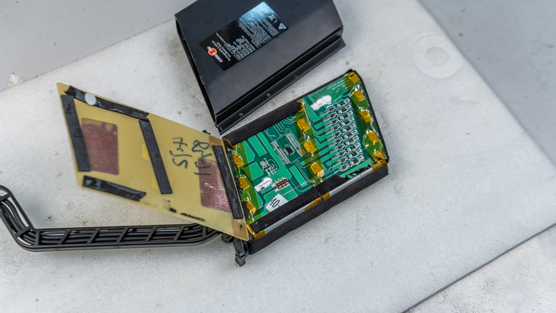
This is the inside the aluminum profile of the battery.
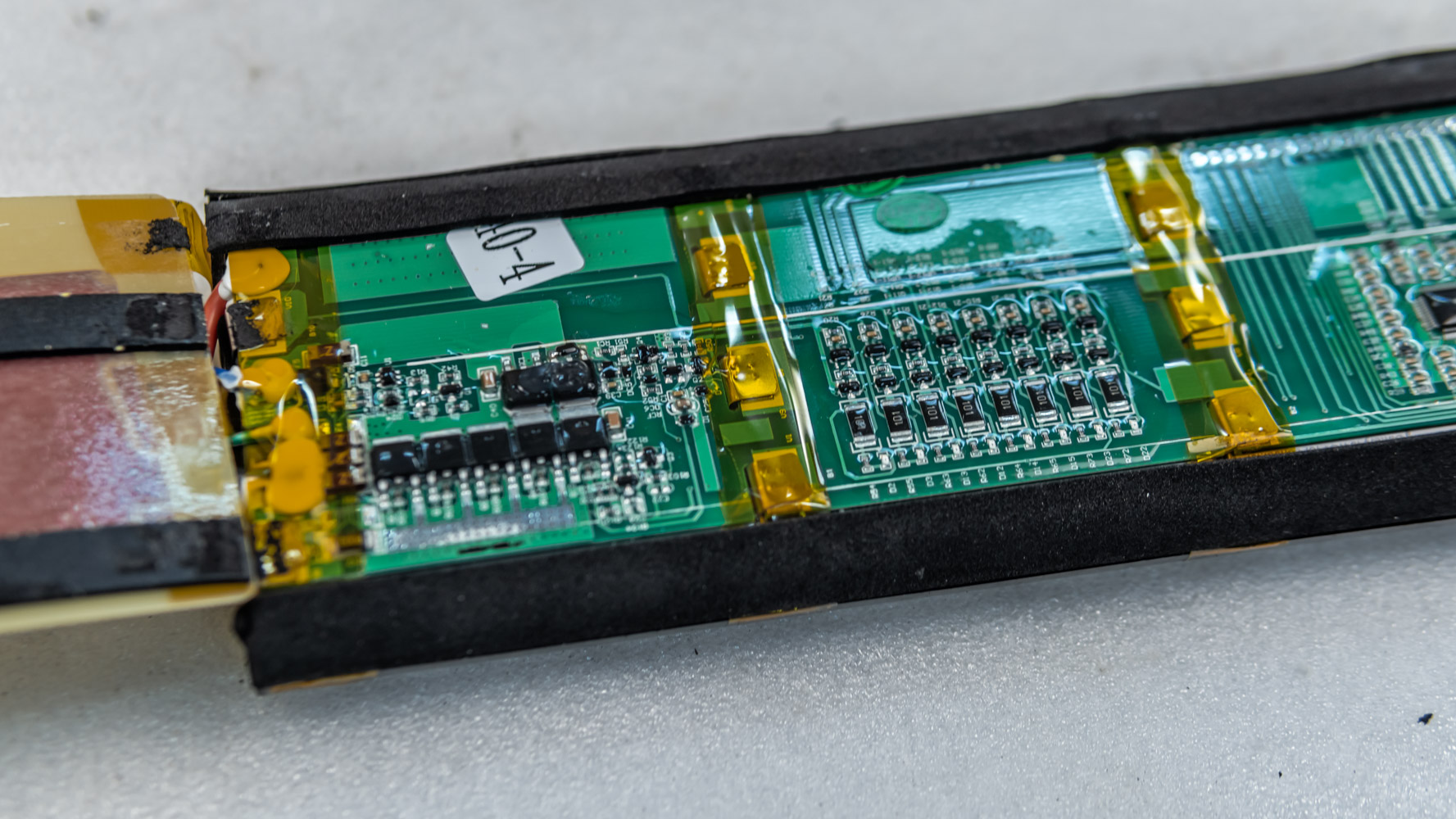
BMS is a bit bigger. There are no fuses here. A whole lot of transistors provide protection of the unit, including protection from the short-circuit as well. I don’t really know how this all works.
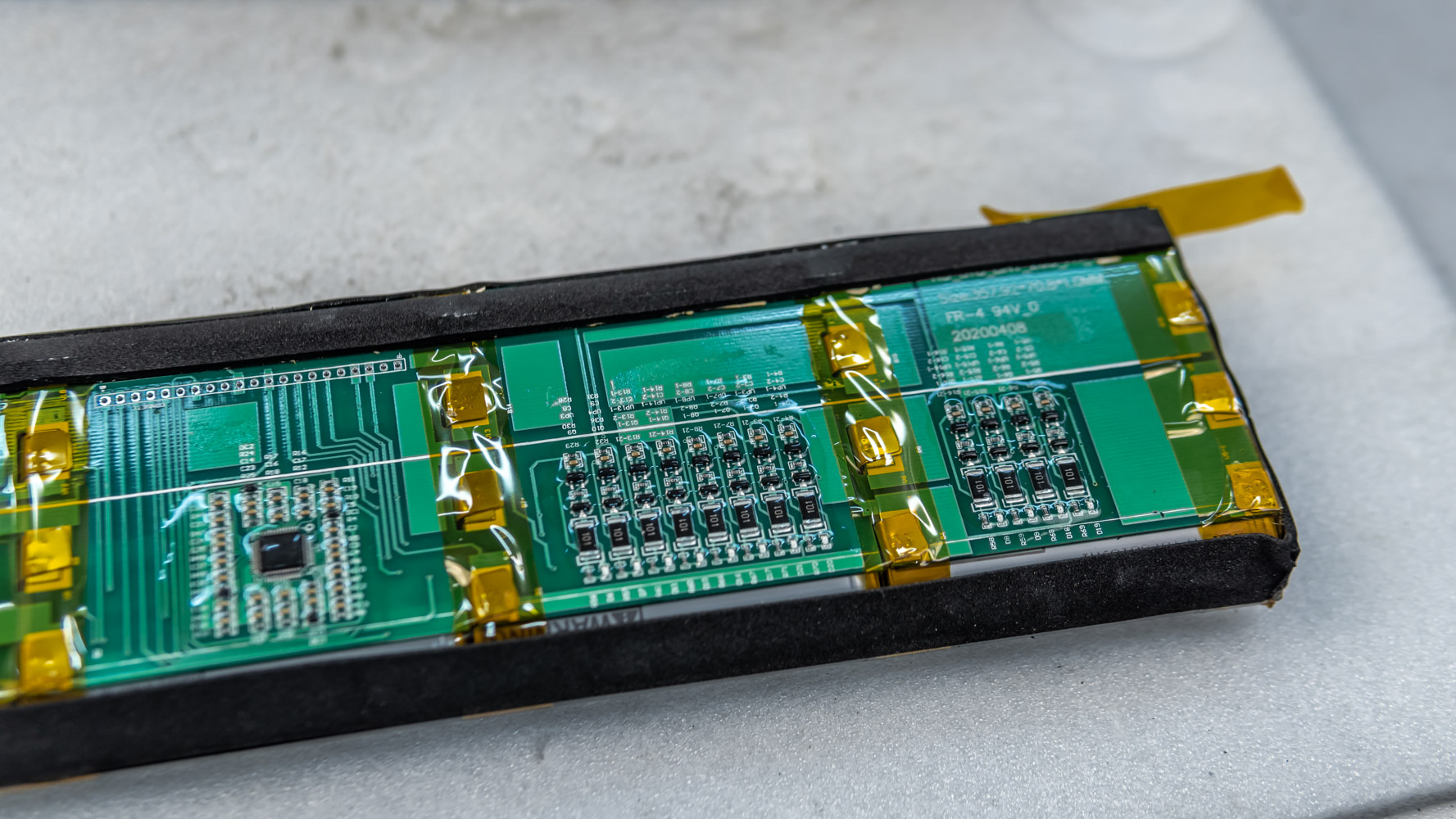
I also did not pick the battery open to find the temperature sensor. I hope it is there somewhere.
When assembling the wheel back, the batteries often start rubbing against the mud protector.
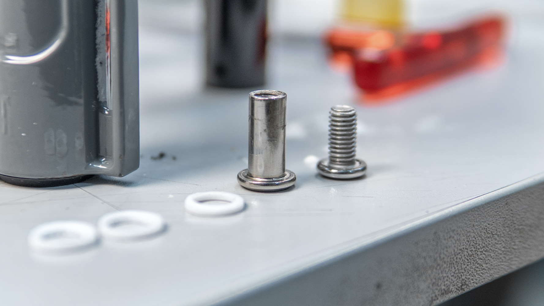
I suggest using these spacers when attaching the battery to minimize rubbing. This is a pair of washers, which will give a little spacing.
The second thing is that when tightening the fixing screws you must use aluminum bar, which comes with the wheel.
The bar allows you to correctly orient battery units and prevent possible distortion. The main thing is not to forget to knock out this bar later, otherwise the suspension will not work as intended.
Screw the batteries so that they do not contact the sliders.
Again, we check how everything works. Then we connect the batteries, complete the assembly of the wheel.
At the very end, we remove the axles for the shock absorber. Don’t forget to treat one of the bushings, which is wedged in the loop of the shock absorber. You can just sand it so it rotates normally during installation. It is convenient to clamp it on the axles, put it in the screwdriver and simply rotate it against the sandpaper.
Then we polish it a little. Do not forget to grease both bushings and install the shock absorber.
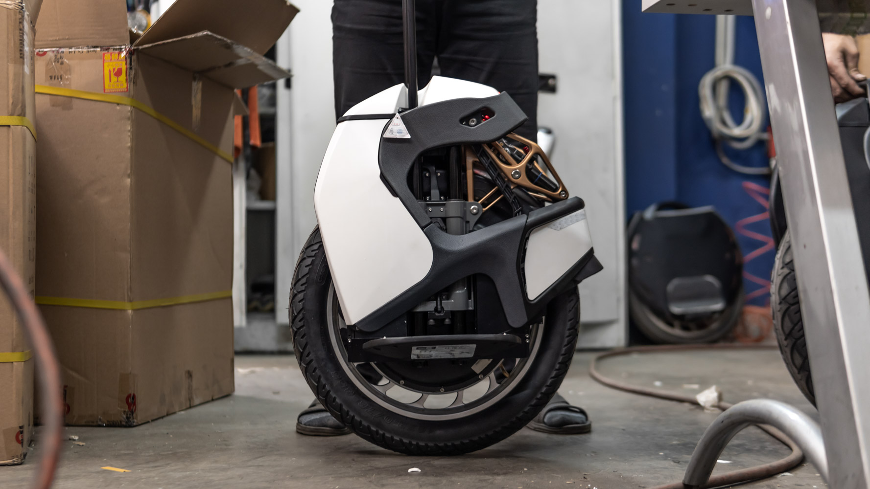
We pump the main space up to about 150psi so that the suspension is fully straightened. We pump the lower space to 50-60psi. Install the plastic bar for pumping, pump the main space to fit your weight. Once again check how the suspension works and you are free to ride. It’s ready now.


Do you want to become a Canadian citizen and have a business?
https://arnikavisa.com/canada-investor-visa-learn-about-investment-immigration
Защита отверстий и инсталляций с помощью Скотча: прочно и безопасно
где скотч [url=http://skotch1.ru/]http://skotch1.ru/[/url].
Прочные мешки для строительного мусора: лучшее качество
мешки строительные купить [url=http://meshki-dlya-stroitelnogo-musora-optom.ru/]http://meshki-dlya-stroitelnogo-musora-optom.ru/[/url].
Хозтовары оптом для каждого типа бизнеса
хозтовары оптом в москве дешево [url=http://hoztovaropt.ru/]http://hoztovaropt.ru/[/url].
Лучший производитель полиэтиленовой продукции
производители упаковочных материалов [url=http://proizvoditel-polietilenovoj-produkcii.ru/]http://proizvoditel-polietilenovoj-produkcii.ru/[/url].
Лучшие полиэтиленовые мешки в наличии
мешки п э [url=http://meshki-polietilenovye1.ru/]http://meshki-polietilenovye1.ru/[/url].
Разумные цены на стрейч пленку
купить стрейч пленку от производителя [url=http://streych-plenka-optom.ru/]http://streych-plenka-optom.ru/[/url].
Продажа полиэтиленовых мешков
мешки упаковочные полиэтиленовые [url=http://meshki-polietilenovye1.ru/]http://meshki-polietilenovye1.ru/[/url].
Лучшее производство полиэтилена от производителя
производство упаковка [url=http://proizvoditel-polietilenovoj-produkcii.ru/]http://proizvoditel-polietilenovoj-produkcii.ru/[/url].
Теплые бахилы для зимних путешествий
купить бахилы в москве [url=http://bahily-optomm.ru/]http://bahily-optomm.ru/[/url].
Самые выгодные предложения на стрейч пленку
куплю стрейч пленку оптом [url=http://streych-plenka-msk1.ru/]http://streych-plenka-msk1.ru/[/url].
Greetings! Very helpful advice in this particular article! Its the little changes that produce the largest changes. Thanks a lot for sharing!
Наш магазин предоставляет лучший выбор товаров для покупки оптом
стрейч пленка оптом [url=http://strejch-plenka-optomm.ru/]http://strejch-plenka-optomm.ru/[/url].
Стильные бахилы для вечеринок
бахилы дешево [url=http://bahily-optomm.ru/]http://bahily-optomm.ru/[/url].
Надежные мешки из полиэтилена
купить полиэтиленовый мешок [url=https://meshki-polietilenovye1.ru/]https://meshki-polietilenovye1.ru/[/url].
Доступная цена
рулонные скатерти одноразовые [url=http://www.skaterti-odnorazovye.ru/]http://www.skaterti-odnorazovye.ru/[/url].
Огромный выбор товара для покупки оптом
стрейч пленка купить оптом от производителя [url=http://strejch-plenka-optomm.ru/]http://strejch-plenka-optomm.ru/[/url].
Выгодно купить губки для мытья посуды оптом у нас
губки для мытья посуды [url=https://gubki-dlya-mytya-posudy-opt.ru]https://gubki-dlya-mytya-posudy-opt.ru[/url].
купить скотч оптом [url=https://skotch-optom-1.ru]https://skotch-optom-1.ru[/url].
Какой выбрать правильный мешок для мусора
Размерный ассортимент мешков для мусора
Какой мусор можно выбрасывать в мешок
Виды мешков для разных типов мусора
Плюсы и минусы пластиковых мешков
Зачем использовать специальные мешки для мусора
Из чего делают мешки для мусора
Какие цвета используются для мешков мусора
Способы правильно закрыть мешок для мусора
Прочные мешки для тяжелого мусора
Оптимальный объем мешка для ежедневного использования
Экологичные мешки для мусора
Где расположить мешок для удобства использования
Какой мешок выбрать для разных типов помещений
Как избежать протечки приблизительно
Значение правильной утилизации мусора в мешок
Как сэкономить на покупке мешков для мусора
Как быстро заменять мешок для мусора
Разновидности мешков для разных типов мусора
Инструкция по правильной утилизации мусора с использованием мешка
Как применять мешок для мусора повторно}
мешок для мусора купить [url=https://www.meshki-dlya-musora-q.ru]https://www.meshki-dlya-musora-q.ru[/url].
Kingsong S18. Rebuilding the suspension. – ECODRIFT
anyjwdzomp
[url=http://www.g94vw05j3is3173n31ptq8n9d46orjr9s.org/]unyjwdzomp[/url]
nyjwdzomp http://www.g94vw05j3is3173n31ptq8n9d46orjr9s.org/
Губки для мытья посуды на любой вкус оптом
купить губки для мытья посуды [url=https://www.gubki-dlya-mytya-posudy-opt.ru]https://www.gubki-dlya-mytya-posudy-opt.ru[/url].
Купить мешки для сброса мусора на доступных условиях
мусорные мешки для мусора [url=https://meshki-dlya-musora-w.ru/]https://meshki-dlya-musora-w.ru/[/url].
Выгодно купить мусорные мешки – у нас всё просто
мусорные мешки цена [url=https://meshki-dlya-musora-r.ru]https://meshki-dlya-musora-r.ru[/url].
Выбирайте качественные пакеты для мусора
2) Сберегите окружающую среду с экологичными мешками для мусора
3) Избавьтесь от мусора с легкостью с при помощи мешков для мусора
4) Оптимальный выбор для утилизации мусора – мешки для мусора
5) Не допускайте загрязнение с помощью мешков для мусора
6) Организуйте свой дом с помощью мешков для мусора
7) Уважайте окружающую среду с надежными мешками для мусора
8) Удобный способ для утилизации мусора – мешки для мусора
9) Необходимое приобретение для любого дома – мешки для мусора
10) Просто сортируйте мусор с помощью различных цветов мешков для мусора
11) Экономьте время и силы с прочными мешками для мусора
12) Защитите окружающую среду вместе с мешками для мусора
13) Простое решение для уборки двора – мешки для мусора
14) Храните уборочные принадлежности в мешках для мусора
15) Качество и экологичность – главные критерии при выборе мешков для мусора
16) Сохраняйте свой двор в чистоте с мешками для мусора
17) Без усилий и забот – утилизируйте мусор с помощью мешков для мусора
18) Интуитивно понятные мешки для мусора упростят вашу жизнь
19) Оптимизируйте пространство с помощью компактных мешков для мусора
20) Защитите свой дом с качественными мешками для мусора
купить мусорные пакеты [url=meshki-dlya-musora-y.ru]meshki-dlya-musora-y.ru[/url].
Недорогие мешки для мусора в продаже
мусорные мешки для мусора [url=https://meshki-dlya-musora-u.ru/]https://meshki-dlya-musora-u.ru/[/url].
Выбирайте качественные мешки для мусора
2) Защитите окружающую среду с экологичными мешками для мусора
3) Избавьтесь от мусора с легкостью с при помощи мешков для мусора
4) Идеальное решение для утилизации мусора – мешки для мусора
5) Держите свой дом с помощью мешков для мусора
6) Упорядочьте свой дом с помощью мешков для мусора
7) Поддержите чистоту с надежными мешками для мусора
8) Простое решение для утилизации мусора – мешки для мусора
9) Продуманное приобретение для любого дома – мешки для мусора
10) Легко сортируйте мусор с помощью различных цветов мешков для мусора
11) Экономьте время и силы с прочными мешками для мусора
12) Поддержите экологию вместе с мешками для мусора
13) Удобный способ для уборки двора – мешки для мусора
14) Сортируйте мусор в мешках для мусора
15) Качество и экологичность – главные критерии при выборе мешков для мусора
16) Сохраняйте свой двор в чистоте с мешками для мусора
17) Без усилий и забот – утилизируйте мусор с помощью мешков для мусора
18) Интуитивно понятные мешки для мусора упростят вашу жизнь
19) Оптимизируйте пространство с помощью компактных мешков для мусора
20) Поддержите чистоту города с качественными мешками для мусора
мешки для мусора [url=http://www.meshki-dlya-musora-i.ru/]http://www.meshki-dlya-musora-i.ru/[/url].
hantik.ee
Expanded Teflon Gasket Tape
Unique Eyeglasses
Gore Tex Gasket Sheet
Designer Eyewear
Tortoiseshell Eyewear
Eptfe Sheet
Gasket Punch Set
Gasket Making Punches
Alibaba Glass Bottles
Sports Bottle With Straw
Frosted Tumbler
Hole Punch Sets Gaskets
http://www.sork.pl
Объемные мешки для сбора мусора по хорошей цене
купить большие пакеты для мусора [url=http://www.meshki-dlya-musora-a.ru]http://www.meshki-dlya-musora-a.ru[/url].
Spiral Wound Gasket with Ribs for Heat Exchanger
N-[(9H-Fluoren-9-ylmethoxy)carbonyl]isoleucin
hcaster.co.kr
N-[(9H-fluoren-9-ylmethoxy)carbonyl]-L-alloisoleucine
Small Copper Nose Crimping Pliers
Multi Purpose Crimping Pliers
N-[(9H-fluoren-9-ylmethoxy)carbonyl]-L-alloisoleucine
Подбирайте качественные пакеты для мусора
2) Сберегите окружающую среду с надежными мешками для мусора
3) Избавьтесь от мусора с легкостью с помощью мешков для мусора
4) Оптимальный выбор для утилизации мусора – мешки для мусора
5) Не допускайте загрязнение с помощью мешков для мусора
6) Организуйте свой дом с с использованием мешков для мусора
7) Уважайте окружающую среду с надежными мешками для мусора
8) Удобный способ для утилизации мусора – мешки для мусора
9) Необходимое приобретение для любого дома – мешки для мусора
10) Легко сортируйте мусор с помощью различных цветов мешков для мусора
11) Экономьте время и силы с прочными мешками для мусора
12) Защитите окружающую среду вместе с мешками для мусора
13) Простое решение для уборки двора – мешки для мусора
14) Сортируйте мусор в мешках для мусора
15) Прочность и долговечность – главные критерии при выборе мешков для мусора
16) Сохраняйте свой двор в чистоте с мешками для мусора
17) Без усилий и забот – утилизируйте мусор с помощью мешков для мусора
18) Простые и практичные мешки для мусора упростят вашу жизнь
19) Оптимизируйте пространство с помощью компактных мешков для мусора
20) Защитите свой дом с качественными мешками для мусора
стоимость мешков для мусора [url=http://meshki-dlya-musora-i.ru/]http://meshki-dlya-musora-i.ru/[/url].
CNC Metal Prototype Services
7km Laser Rangefinder Module
Where is Food Truck usually used
skylets.or.jp
5000 Ft Machine Pallet Wrap Stretch Film
Stretch Film For Machine
High Density Lldpe Stretch Film
“Connettore maschio SMA antenna GPS+GSM+Am/FM”
xuongsi.com
Circuit Breaker
Die Casting Mechanical And Electrical Shroud Fan
Dispositivi GPS per il monitoraggio dei veicoli in Italia
Electrical Distribution Systems
GHz
3D HIFU 12 Lines Smas Facial Lifting Hifu for Clinic
http://www.leilia.net
Gold Filled Jewelry
Best Bridal Jewelry
7D HIFU Vertical Ultrasound Ultraformer Smas Face Tightening
4D HIFU V Max Liposonix Face Lifting RF Microneedle Fractional
Jewelry Gold
What is the function of rubber seal
Netsource Technology
Healthcare Procurement
Advantages of Laser Pigmentation Treatment
Outdoor Travel Soft Cooler Bag
http://www.radioklub.blansko.net
Electronics Part
Подбирайте качественные мешки для мусора
2) Защитите окружающую среду с надежными мешками для мусора
3) Уберите от мусора с легкостью с помощью мешков для мусора
4) Оптимальный выбор для утилизации мусора – мешки для мусора
5) Не допускайте загрязнение с помощью мешков для мусора
6) Упорядочьте свой дом с помощью мешков для мусора
7) Поддержите чистоту с качественными мешками для мусора
8) Простое решение для утилизации мусора – мешки для мусора
9) Продуманное приобретение для любого дома – мешки для мусора
10) Легко сортируйте мусор с помощью различных цветов мешков для мусора
11) Экономьте время и силы с надежными мешками для мусора
12) Поддержите экологию вместе с мешками для мусора
13) Простое решение для уборки двора – мешки для мусора
14) Храните уборочные принадлежности в мешках для мусора
15) Прочность и долговечность – главные критерии при выборе мешков для мусора
16) Сохраняйте свой двор в чистоте с мешками для мусора
17) Без усилий и забот – утилизируйте мусор с помощью мешков для мусора
18) Простые и практичные мешки для мусора упростят вашу жизнь
19) Оптимизируйте пространство с помощью компактных мешков для мусора
20) Защитите свой дом с качественными мешками для мусора
купить большие мешки для мусора [url=https://meshki-dlya-musora-d.ru]https://meshki-dlya-musora-d.ru[/url].
Carbon Fiber Boom
szklarski.pl
Zinc Plated Grade 4 Garde 8 Hex Flange Serrated Nut- DIN6923
Carbon Fiber Canopy
DIN 6923 Carbon Steel Plain Zinc Plated Serrated Hex Flange Nut
Carbon Fiber Key Chain
Color Zinc Plated Round Base T nuts With Three Brad Hole Tee Nut
speelmrgreen.nl
Swimming Pool Lighting Design
A2-70 A4-80 M8 M10 DIN931 ISO4014 Stainless Steel half thread Hex Bolt
Changing Pool Light Fixture
1/4-2″ASME/ANSI B 18.2.1 Grade 2 5 8 Zinc Plated Hex Head Cap Screws
Stainless Steel A2-70 A4-80 Heavy Hex Bolt with Nut
Changing Pool Light Fixture
Объемные мешки для сбора мусора по хорошей цене
мешки под мусор [url=https://meshki-dlya-musora-u.ru/]https://meshki-dlya-musora-u.ru/[/url].
Single Stage Fire Pump
Transglutaminase
What is a rod end bearing
High Pressure Pump
Common classification of Three Wheels Electric Car
http://www.clearwaterrv.net
High Pressure Vane Pump
Выбирайте качественные пакеты для мусора
2) Сберегите окружающую среду с экологичными мешками для мусора
3) Избавьтесь от мусора с легкостью с при помощи мешков для мусора
4) Идеальное решение для утилизации мусора – мешки для мусора
5) Не допускайте загрязнение с помощью мешков для мусора
6) Организуйте свой дом с помощью мешков для мусора
7) Уважайте окружающую среду с надежными мешками для мусора
8) Удобный способ для утилизации мусора – мешки для мусора
9) Продуманное приобретение для любого дома – мешки для мусора
10) Легко сортируйте мусор с помощью различных цветов мешков для мусора
11) Экономьте время и силы с надежными мешками для мусора
12) Защитите окружающую среду вместе с мешками для мусора
13) Удобный способ для уборки двора – мешки для мусора
14) Храните уборочные принадлежности в мешках для мусора
15) Прочность и долговечность – главные критерии при выборе мешков для мусора
16) Держите свой дом в чистоте с мешками для мусора
17) Легко и быстро – утилизируйте мусор с помощью мешков для мусора
18) Интуитивно понятные мешки для мусора упростят вашу жизнь
19) Экономьте место с помощью компактных мешков для мусора
20) Поддержите чистоту города с качественными мешками для мусора
мешки для мусора купить [url=http://meshki-dlya-musora-g.ru/]http://meshki-dlya-musora-g.ru/[/url].
Magnetic Beads For Dna Purification
http://www.winsta.jp
Serum Rna Extraction Protocol
N7000-1 PCB
Total Rna Extraction
N4000-13EPSI PCB
N4000-13 PCB
Надёжная продажа мешков для выноса мусора
где купить мешки для мусора [url=https://www.meshki-dlya-musora-h.ru]https://www.meshki-dlya-musora-h.ru[/url].
Woltmann Removable Cold Water Meter
Home Pure Sine Wave Inverter Fan
Woltman Flange Hot Water Meter
misiniec.pl
2510 Fan
Dc 12025 Copper Duct Cooling Fan
Horizontal Woltmann Cold Water Meter
Hi, unfortunately, I faced challenges with the slow loading speed of your website, leading to frustration. I recommend a service, linked below, that I’ve used personally to significantly improve my website speed. I really love your website…Optimize now
The role of PU Seal Ring
The working principle and use of the push button switch
Customized Floating Oil Seal
High Pressure Oil Seal
What is the purpose of the Battery adapter
cebg.guarico.gob.ve
Mechanical Face Seal Design
CNC Auto Parts
High Precision Metal Stamping
Aluminum Car Parts
Medical Devices CNC Machining
Aluminium Extrusion Fittings
okinogu.or.jp
Stairs Protection
Выбирайте качественные мешки для мусора
2) Защитите окружающую среду с экологичными мешками для мусора
3) Уберите от мусора с легкостью с при помощи мешков для мусора
4) Идеальное решение для утилизации мусора – мешки для мусора
5) Держите свой дом с помощью мешков для мусора
6) Организуйте свой дом с с использованием мешков для мусора
7) Уважайте окружающую среду с надежными мешками для мусора
8) Удобный способ для утилизации мусора – мешки для мусора
9) Продуманное приобретение для любого дома – мешки для мусора
10) Легко сортируйте мусор с помощью различных цветов мешков для мусора
11) Экономьте время и силы с надежными мешками для мусора
12) Поддержите экологию вместе с мешками для мусора
13) Удобный способ для уборки двора – мешки для мусора
14) Храните уборочные принадлежности в мешках для мусора
15) Прочность и долговечность – главные критерии при выборе мешков для мусора
16) Держите свой дом в чистоте с мешками для мусора
17) Без усилий и забот – утилизируйте мусор с помощью мешков для мусора
18) Интуитивно понятные мешки для мусора упростят вашу жизнь
19) Оптимизируйте пространство с помощью компактных мешков для мусора
20) Поддержите чистоту города с качественными мешками для мусора
пакеты мусорные [url=https://www.meshki-dlya-musora-g.ru/]https://www.meshki-dlya-musora-g.ru/[/url].
Stainless Steel DIN934 Hex Nut
lavidamata.xyz
Induction Double Burner
Electric Hot Plates
Solar Panel Stainless Fastener Hanger Bolt with Self Drilling
Stainless Hanger Bolts for Solar Mount System Hanger Bolt for Steel
Noxton Induction Hob
Zinc Plated Fine Thread Castle Nut
Stainless Steel A2 DIN557 Square Nut
Hydraulic Hose Crimping Machine
Zinc Plated Steel Castle Nuts
Copper Pipe Pressing Tool
Pipe Crimping Tool
gataquenha.com
XEvil 5.0 automatically solve most kind of captchas, [/b][/color]
Including such type of captchas: ReCaptcha v.2, ReCaptcha v.3, Hotmail, Google, SolveMedia, BitcoinFaucet, Steam, Amazon, Twitter, Microsoft, Twitch, Outlook, +12000
+ hCaptcha, ArkoseLabs FunCaptcha, ReCaptcha Enterprize supported in new XEvil 6.0!
1.) Fast, easy, precisionly
XEvil is the fastest captcha killer in the world. Its has no solving limits, no threads number limits
you can solve even 1.000.000.000 captchas per day and it will cost 0 (ZERO) USD! Just buy license for 59 USD and all!
2.) Several APIs support
XEvil supports more than 6 different, worldwide known API: 2captcha.com, anti-captcha (antigate), rucaptcha.com, death-by-captcha, etc.
just send your captcha via HTTP request, as you can send into any of that service – and XEvil will solve your captcha!
So, XEvil is compatible with hundreds of applications for SEO/SMM/password recovery/parsing/posting/clicking/cryptocurrency/etc.
3.) Useful support and manuals
After purchase, you got access to a private tech.support forum, Wiki, Skype/Telegram online support
Developers will train XEvil to your type of captcha for FREE and very fast – just send them examples
4.) How to get free trial use of XEvil full version?
– Try to search in Google “Home of XEvil”
– you will find IPs with opened port 80 of XEvil users (click on any IP to ensure)
– try to send your captcha via 2captcha API ino one of that IPs
– if you got BAD KEY error, just tru another IP
– enjoy! 🙂
– (its not work for hCaptcha!)
WARNING: Free XEvil DEMO does NOT support ReCaptcha, hCaptcha and most other types of captcha!
http://XEvil.Net/
Masterbatch
Square Undermount Sink
Black Masterbatch
schools.bidyaan.com
Outdoor Urinal
Urinal Toilet
Black Masterbatch
XEvil 5.0 automatically solve most kind of captchas, [/b][/color]
Including such type of captchas: ReCaptcha-2, ReCaptcha v.3, Hotmail (Microsoft), Google captcha, Solve Media, BitcoinFaucet, Steam, Amazon, Twitter, Microsoft, Twitch, Outlook, +12000
+ hCaptcha, ArkoseLabs FunCaptcha, ReCaptcha Enterprize supported in new XEvil 6.0!
1.) Fast, easy, precisionly
XEvil is the fastest captcha killer in the world. Its has no solving limits, no threads number limits
you can solve even 1.000.000.000 captchas per day and it will cost 0 (ZERO) USD! Just buy license for 59 USD and all!
2.) Several APIs support
XEvil supports more than 6 different, worldwide known API: 2Captcha, anti-captcha (antigate), rucaptcha.com, DeathByCaptcha, etc.
just send your captcha via HTTP request, as you can send into any of that service – and XEvil will solve your captcha!
So, XEvil is compatible with hundreds of applications for SEO/SMM/password recovery/parsing/posting/clicking/cryptocurrency/etc.
3.) Useful support and manuals
After purchase, you got access to a private tech.support forum, Wiki, Skype/Telegram online support
Developers will train XEvil to your type of captcha for FREE and very fast – just send them examples
4.) How to get free trial use of XEvil full version?
– Try to search in Google “Home of XEvil”
– you will find IPs with opened port 80 of XEvil users (click on any IP to ensure)
– try to send your captcha via 2captcha API ino one of that IPs
– if you got BAD KEY error, just tru another IP
– enjoy! 🙂
– (its not work for hCaptcha!)
WARNING: Free XEvil DEMO does NOT support ReCaptcha, hCaptcha and most other types of captcha!
http://XEvil.Net/
XEvil 6.0 automatically solve most kind of captchas, [/b][/color]
Including such type of captchas: ReCaptcha v.2, ReCaptcha v.3, Hotmail (Microsoft), Google captcha, SolveMedia, BitcoinFaucet, Steam, Amazon, Twitter, Microsoft, Twitch, Outlook, +12000
+ hCaptcha, ArkoseLabs FunCaptcha, ReCaptcha Enterprize supported in new XEvil 6.0!
1.) Fast, easy, precisionly
XEvil is the fastest captcha killer in the world. Its has no solving limits, no threads number limits
you can solve even 1.000.000.000 captchas per day and it will cost 0 (ZERO) USD! Just buy license for 59 USD and all!
2.) Several APIs support
XEvil supports more than 6 different, worldwide known API: 2captcha.com, anti-captcha (antigate), RuCaptcha, death-by-captcha, etc.
just send your captcha via HTTP request, as you can send into any of that service – and XEvil will solve your captcha!
So, XEvil is compatible with hundreds of applications for SEO/SMM/password recovery/parsing/posting/clicking/cryptocurrency/etc.
3.) Useful support and manuals
After purchase, you got access to a private tech.support forum, Wiki, Skype/Telegram online support
Developers will train XEvil to your type of captcha for FREE and very fast – just send them examples
4.) How to get free trial use of XEvil full version?
– Try to search in Google “Home of XEvil”
– you will find IPs with opened port 80 of XEvil users (click on any IP to ensure)
– try to send your captcha via 2captcha API ino one of that IPs
– if you got BAD KEY error, just tru another IP
– enjoy! 🙂
– (its not work for hCaptcha!)
WARNING: Free XEvil DEMO does NOT support ReCaptcha, hCaptcha and most other types of captcha!
http://xrumersale.site/
sork.pl
HC420LAD+Z Color Coated Galvanized Steel Coil
H180BD+Z Color Coated Galvanized Steel Coil
Epoxy Coating Machine
Spraying Equipment
Panel Spray Machine
S220GD+Z Color Coated Galvanized Steel Coil
XEvil 6.0 automatically solve most kind of captchas, [/b][/color]
Including such type of captchas: ReCaptcha v.2, ReCaptcha-3, Hotmail (Microsoft), Google captcha, SolveMedia, BitcoinFaucet, Steam, Amazon, Twitter, Microsoft, Twitch, Outlook, +12000
+ hCaptcha, ArkoseLabs FunCaptcha, ReCaptcha Enterprize supported in new XEvil 6.0!
1.) Fast, easy, precisionly
XEvil is the fastest captcha killer in the world. Its has no solving limits, no threads number limits
you can solve even 1.000.000.000 captchas per day and it will cost 0 (ZERO) USD! Just buy license for 59 USD and all!
2.) Several APIs support
XEvil supports more than 6 different, worldwide known API: 2Captcha, anti-captcha (antigate), rucaptcha.com, DeathByCaptcha, etc.
just send your captcha via HTTP request, as you can send into any of that service – and XEvil will solve your captcha!
So, XEvil is compatible with hundreds of applications for SEO/SMM/password recovery/parsing/posting/clicking/cryptocurrency/etc.
3.) Useful support and manuals
After purchase, you got access to a private tech.support forum, Wiki, Skype/Telegram online support
Developers will train XEvil to your type of captcha for FREE and very fast – just send them examples
4.) How to get free trial use of XEvil full version?
– Try to search in Google “Home of XEvil”
– you will find IPs with opened port 80 of XEvil users (click on any IP to ensure)
– try to send your captcha via 2captcha API ino one of that IPs
– if you got BAD KEY error, just tru another IP
– enjoy! 🙂
– (its not work for hCaptcha!)
WARNING: Free XEvil DEMO does NOT support ReCaptcha, hCaptcha and most other types of captcha!
http://xrumersale.site/
Folding Camping Table
Powerful Car Vacuum
Mini Vacuum Cleaner for Home
Small Vacuum Cleaner for Car
Portable Car Fridge Freezer
Tools & Hardware
http://www.haedang.vn
XEvil 5.0 automatically solve most kind of captchas, [/b][/color]
Including such type of captchas: ReCaptcha v.2, ReCaptcha v.3, Hotmail, Google, SolveMedia, BitcoinFaucet, Steam, Amazon, Twitter, Microsoft, Twitch, Outlook, +12k
+ hCaptcha, ArkoseLabs FunCaptcha, ReCaptcha Enterprize supported in new XEvil 6.0!
1.) Fast, easy, precisionly
XEvil is the fastest captcha killer in the world. Its has no solving limits, no threads number limits
you can solve even 1.000.000.000 captchas per day and it will cost 0 (ZERO) USD! Just buy license for 59 USD and all!
2.) Several APIs support
XEvil supports more than 6 different, worldwide known API: 2captcha.com, anti-captcha (antigate), rucaptcha.com, DeathByCaptcha, etc.
just send your captcha via HTTP request, as you can send into any of that service – and XEvil will solve your captcha!
So, XEvil is compatible with hundreds of applications for SEO/SMM/password recovery/parsing/posting/clicking/cryptocurrency/etc.
3.) Useful support and manuals
After purchase, you got access to a private tech.support forum, Wiki, Skype/Telegram online support
Developers will train XEvil to your type of captcha for FREE and very fast – just send them examples
4.) How to get free trial use of XEvil full version?
– Try to search in Google “Home of XEvil”
– you will find IPs with opened port 80 of XEvil users (click on any IP to ensure)
– try to send your captcha via 2captcha API ino one of that IPs
– if you got BAD KEY error, just tru another IP
– enjoy! 🙂
– (its not work for hCaptcha!)
WARNING: Free XEvil DEMO does NOT support ReCaptcha, hCaptcha and most other types of captcha!
http://xrumersale.site/
XEvil 5.0 automatically solve most kind of captchas, [/b][/color]
Including such type of captchas: ReCaptcha-2, ReCaptcha-3, Hotmail (Microsoft), Google captcha, Solve Media, BitcoinFaucet, Steam, Amazon, Twitter, Microsoft, Twitch, Outlook, +12k
+ hCaptcha, ArkoseLabs FunCaptcha, ReCaptcha Enterprize supported in new XEvil 6.0!
1.) Fast, easy, precisionly
XEvil is the fastest captcha killer in the world. Its has no solving limits, no threads number limits
you can solve even 1.000.000.000 captchas per day and it will cost 0 (ZERO) USD! Just buy license for 59 USD and all!
2.) Several APIs support
XEvil supports more than 6 different, worldwide known API: 2Captcha, anti-captcha (antigate), RuCaptcha, DeathByCaptcha, etc.
just send your captcha via HTTP request, as you can send into any of that service – and XEvil will solve your captcha!
So, XEvil is compatible with hundreds of applications for SEO/SMM/password recovery/parsing/posting/clicking/cryptocurrency/etc.
3.) Useful support and manuals
After purchase, you got access to a private tech.support forum, Wiki, Skype/Telegram online support
Developers will train XEvil to your type of captcha for FREE and very fast – just send them examples
4.) How to get free trial use of XEvil full version?
– Try to search in Google “Home of XEvil”
– you will find IPs with opened port 80 of XEvil users (click on any IP to ensure)
– try to send your captcha via 2captcha API ino one of that IPs
– if you got BAD KEY error, just tru another IP
– enjoy! 🙂
– (its not work for hCaptcha!)
WARNING: Free XEvil DEMO does NOT support ReCaptcha, hCaptcha and most other types of captcha!
http://xrumersale.site/
XEvil 5.0 automatically solve most kind of captchas, [/b][/color]
Including such type of captchas: ReCaptcha-2, ReCaptcha v.3, Hotmail (Microsoft), Google, SolveMedia, BitcoinFaucet, Steam, Amazon, Twitter, Microsoft, Twitch, Outlook, +12000
+ hCaptcha, ArkoseLabs FunCaptcha, ReCaptcha Enterprize supported in new XEvil 6.0!
1.) Fast, easy, precisionly
XEvil is the fastest captcha killer in the world. Its has no solving limits, no threads number limits
you can solve even 1.000.000.000 captchas per day and it will cost 0 (ZERO) USD! Just buy license for 59 USD and all!
2.) Several APIs support
XEvil supports more than 6 different, worldwide known API: 2captcha.com, anti-captcha (antigate), rucaptcha.com, DeathByCaptcha, etc.
just send your captcha via HTTP request, as you can send into any of that service – and XEvil will solve your captcha!
So, XEvil is compatible with hundreds of applications for SEO/SMM/password recovery/parsing/posting/clicking/cryptocurrency/etc.
3.) Useful support and manuals
After purchase, you got access to a private tech.support forum, Wiki, Skype/Telegram online support
Developers will train XEvil to your type of captcha for FREE and very fast – just send them examples
4.) How to get free trial use of XEvil full version?
– Try to search in Google “Home of XEvil”
– you will find IPs with opened port 80 of XEvil users (click on any IP to ensure)
– try to send your captcha via 2captcha API ino one of that IPs
– if you got BAD KEY error, just tru another IP
– enjoy! 🙂
– (its not work for hCaptcha!)
WARNING: Free XEvil DEMO does NOT support ReCaptcha, hCaptcha and most other types of captcha!
http://xrumersale.site/
Подбирайте качественные мешки для мусора
2) Сберегите окружающую среду с надежными мешками для мусора
3) Уберите от мусора с легкостью с при помощи мешков для мусора
4) Идеальное решение для утилизации мусора – мешки для мусора
5) Не допускайте загрязнение с помощью мешков для мусора
6) Упорядочьте свой дом с с использованием мешков для мусора
7) Поддержите чистоту с надежными мешками для мусора
8) Удобный способ для утилизации мусора – мешки для мусора
9) Продуманное приобретение для любого дома – мешки для мусора
10) Просто сортируйте мусор с помощью различных цветов мешков для мусора
11) Экономьте время и силы с прочными мешками для мусора
12) Поддержите экологию вместе с мешками для мусора
13) Удобный способ для уборки двора – мешки для мусора
14) Сортируйте мусор в мешках для мусора
15) Прочность и долговечность – главные критерии при выборе мешков для мусора
16) Держите свой дом в чистоте с мешками для мусора
17) Легко и быстро – утилизируйте мусор с помощью мешков для мусора
18) Интуитивно понятные мешки для мусора упростят вашу жизнь
19) Экономьте место с помощью компактных мешков для мусора
20) Защитите свой дом с качественными мешками для мусора
мешок для мусора купить [url=http://meshki-dlya-musora-k.ru/]http://meshki-dlya-musora-k.ru/[/url].
Надежные мешки для мусора на все случаи жизни
пакеты для мусора цена [url=https://meshki-dlya-musora-z.ru/]https://meshki-dlya-musora-z.ru/[/url].
Качественные мешки для мусора по доступным ценам
мешки мусорные [url=https://www.meshki-dlya-musora-h.ru/]https://www.meshki-dlya-musora-h.ru/[/url].
XEvil 6.0 automatically solve most kind of captchas, [/b][/color]
Including such type of captchas: ReCaptcha-2, ReCaptcha v.3, Hotmail (Microsoft), Google, Solve Media, BitcoinFaucet, Steam, Amazon, Twitter, Microsoft, Twitch, Outlook, +12000
+ hCaptcha, ArkoseLabs FunCaptcha, ReCaptcha Enterprize supported in new XEvil 6.0!
1.) Fast, easy, precisionly
XEvil is the fastest captcha killer in the world. Its has no solving limits, no threads number limits
you can solve even 1.000.000.000 captchas per day and it will cost 0 (ZERO) USD! Just buy license for 59 USD and all!
2.) Several APIs support
XEvil supports more than 6 different, worldwide known API: 2captcha.com, anti-captcha (antigate), rucaptcha.com, death-by-captcha, etc.
just send your captcha via HTTP request, as you can send into any of that service – and XEvil will solve your captcha!
So, XEvil is compatible with hundreds of applications for SEO/SMM/password recovery/parsing/posting/clicking/cryptocurrency/etc.
3.) Useful support and manuals
After purchase, you got access to a private tech.support forum, Wiki, Skype/Telegram online support
Developers will train XEvil to your type of captcha for FREE and very fast – just send them examples
4.) How to get free trial use of XEvil full version?
– Try to search in Google “Home of XEvil”
– you will find IPs with opened port 80 of XEvil users (click on any IP to ensure)
– try to send your captcha via 2captcha API ino one of that IPs
– if you got BAD KEY error, just tru another IP
– enjoy! 🙂
– (its not work for hCaptcha!)
WARNING: Free XEvil DEMO does NOT support ReCaptcha, hCaptcha and most other types of captcha!
http://xrumersale.site/
Carbide Bar
Stainless Steel Pan Head Steel Security Button Head Bolts Security SS Wood Self Tapping Screw
Mining Tips
Stainless Steel 316 Deck Concrete Flat Head Machine Tek Screw Hook for Wood Screw
Hexagon Socket Stainless?Steel?304 316 Low Socket Head Cap?Screws Thread
Tungsten Carbide Blanks
http://www.trimolotka.ru
XEvil 5.0 automatically solve most kind of captchas, [/b][/color]
Including such type of captchas: ReCaptcha-2, ReCaptcha v.3, Hotmail, Google, Solve Media, BitcoinFaucet, Steam, Amazon, Twitter, Microsoft, Twitch, Outlook, +12000
+ hCaptcha, ArkoseLabs FunCaptcha, ReCaptcha Enterprize supported in new XEvil 6.0!
1.) Fast, easy, precisionly
XEvil is the fastest captcha killer in the world. Its has no solving limits, no threads number limits
you can solve even 1.000.000.000 captchas per day and it will cost 0 (ZERO) USD! Just buy license for 59 USD and all!
2.) Several APIs support
XEvil supports more than 6 different, worldwide known API: 2captcha.com, anti-captcha (antigate), rucaptcha.com, death-by-captcha, etc.
just send your captcha via HTTP request, as you can send into any of that service – and XEvil will solve your captcha!
So, XEvil is compatible with hundreds of applications for SEO/SMM/password recovery/parsing/posting/clicking/cryptocurrency/etc.
3.) Useful support and manuals
After purchase, you got access to a private tech.support forum, Wiki, Skype/Telegram online support
Developers will train XEvil to your type of captcha for FREE and very fast – just send them examples
4.) How to get free trial use of XEvil full version?
– Try to search in Google “Home of XEvil”
– you will find IPs with opened port 80 of XEvil users (click on any IP to ensure)
– try to send your captcha via 2captcha API ino one of that IPs
– if you got BAD KEY error, just tru another IP
– enjoy! 🙂
– (its not work for hCaptcha!)
WARNING: Free XEvil DEMO does NOT support ReCaptcha, hCaptcha and most other types of captcha!
http://xrumersale.site/
XEvil 6.0 automatically solve most kind of captchas, [/b][/color]
Including such type of captchas: ReCaptcha v.2, ReCaptcha-3, Hotmail (Microsoft), Google captcha, Solve Media, BitcoinFaucet, Steam, Amazon, Twitter, Microsoft, Twitch, Outlook, +12000
+ hCaptcha, ArkoseLabs FunCaptcha, ReCaptcha Enterprize supported in new XEvil 6.0!
1.) Fast, easy, precisionly
XEvil is the fastest captcha killer in the world. Its has no solving limits, no threads number limits
you can solve even 1.000.000.000 captchas per day and it will cost 0 (ZERO) USD! Just buy license for 59 USD and all!
2.) Several APIs support
XEvil supports more than 6 different, worldwide known API: 2captcha.com, anti-captcha (antigate), rucaptcha.com, DeathByCaptcha, etc.
just send your captcha via HTTP request, as you can send into any of that service – and XEvil will solve your captcha!
So, XEvil is compatible with hundreds of applications for SEO/SMM/password recovery/parsing/posting/clicking/cryptocurrency/etc.
3.) Useful support and manuals
After purchase, you got access to a private tech.support forum, Wiki, Skype/Telegram online support
Developers will train XEvil to your type of captcha for FREE and very fast – just send them examples
4.) How to get free trial use of XEvil full version?
– Try to search in Google “Home of XEvil”
– you will find IPs with opened port 80 of XEvil users (click on any IP to ensure)
– try to send your captcha via 2captcha API ino one of that IPs
– if you got BAD KEY error, just tru another IP
– enjoy! 🙂
– (its not work for hCaptcha!)
WARNING: Free XEvil DEMO does NOT support ReCaptcha, hCaptcha and most other types of captcha!
http://XEvil.Net/
XEvil 6.0 automatically solve most kind of captchas, [/b][/color]
Including such type of captchas: ReCaptcha v.2, ReCaptcha-3, Hotmail, Google, Solve Media, BitcoinFaucet, Steam, Amazon, Twitter, Microsoft, Twitch, Outlook, +12k
+ hCaptcha, ArkoseLabs FunCaptcha, ReCaptcha Enterprize supported in new XEvil 6.0!
1.) Fast, easy, precisionly
XEvil is the fastest captcha killer in the world. Its has no solving limits, no threads number limits
you can solve even 1.000.000.000 captchas per day and it will cost 0 (ZERO) USD! Just buy license for 59 USD and all!
2.) Several APIs support
XEvil supports more than 6 different, worldwide known API: 2Captcha, anti-captcha (antigate), rucaptcha.com, DeathByCaptcha, etc.
just send your captcha via HTTP request, as you can send into any of that service – and XEvil will solve your captcha!
So, XEvil is compatible with hundreds of applications for SEO/SMM/password recovery/parsing/posting/clicking/cryptocurrency/etc.
3.) Useful support and manuals
After purchase, you got access to a private tech.support forum, Wiki, Skype/Telegram online support
Developers will train XEvil to your type of captcha for FREE and very fast – just send them examples
4.) How to get free trial use of XEvil full version?
– Try to search in Google “Home of XEvil”
– you will find IPs with opened port 80 of XEvil users (click on any IP to ensure)
– try to send your captcha via 2captcha API ino one of that IPs
– if you got BAD KEY error, just tru another IP
– enjoy! 🙂
– (its not work for hCaptcha!)
WARNING: Free XEvil DEMO does NOT support ReCaptcha, hCaptcha and most other types of captcha!
http://XEvil.Net/
XEvil 5.0 automatically solve most kind of captchas, [/b][/color]
Including such type of captchas: ReCaptcha-2, ReCaptcha v.3, Hotmail (Microsoft), Google captcha, Solve Media, BitcoinFaucet, Steam, Amazon, Twitter, Microsoft, Twitch, Outlook, +12000
+ hCaptcha, ArkoseLabs FunCaptcha, ReCaptcha Enterprize supported in new XEvil 6.0!
1.) Fast, easy, precisionly
XEvil is the fastest captcha killer in the world. Its has no solving limits, no threads number limits
you can solve even 1.000.000.000 captchas per day and it will cost 0 (ZERO) USD! Just buy license for 59 USD and all!
2.) Several APIs support
XEvil supports more than 6 different, worldwide known API: 2captcha.com, anti-captchas.com (antigate), RuCaptcha, DeathByCaptcha, etc.
just send your captcha via HTTP request, as you can send into any of that service – and XEvil will solve your captcha!
So, XEvil is compatible with hundreds of applications for SEO/SMM/password recovery/parsing/posting/clicking/cryptocurrency/etc.
3.) Useful support and manuals
After purchase, you got access to a private tech.support forum, Wiki, Skype/Telegram online support
Developers will train XEvil to your type of captcha for FREE and very fast – just send them examples
4.) How to get free trial use of XEvil full version?
– Try to search in Google “Home of XEvil”
– you will find IPs with opened port 80 of XEvil users (click on any IP to ensure)
– try to send your captcha via 2captcha API ino one of that IPs
– if you got BAD KEY error, just tru another IP
– enjoy! 🙂
– (its not work for hCaptcha!)
WARNING: Free XEvil DEMO does NOT support ReCaptcha, hCaptcha and most other types of captcha!
http://xrumersale.site/
Pointer Fuel Pump 1994-2010
Saveiro Fuel Pump 1994-2010
Big Floor Mirror
http://www.eroticastore.nl
Golf Fuel Pump 1994-2002
Black Metal Mirror
Black Frame Full Length Mirror
cutting machine waterjet ruby orifice
What is Carbon Steel Investment Casting Parts made of
S Glass Fiber
conical cork stoppers
Fibreglass Rendering Mesh Roll
pclgame.online
Fibreglass Fibres
Только лучшие мешки для мусора для Вас
большие мешки для мусора [url=https://www.meshki-dlya-musora-h.ru/]https://www.meshki-dlya-musora-h.ru/[/url].
Electric Chaff Cutter
Creative Sketchbook
Pelletizer Machine For Animal Feeds
Easy Watercolour
http://www.setsatian.ac.th
Chaff Cutter For Hay
single carriage shoe upper flat knitting machine
Anionic Flocculant Liquid
Women S Sweaters
http://www.ruoungo.vn
Advantages of Brass Nuts
Pullover Womens Sweater
Knit Cardigan
Features of Commercial Displays
Надежные мешки для мусора на все случаи жизни
большие мешки для мусора цена [url=https://meshki-dlya-musora-z.ru/]https://meshki-dlya-musora-z.ru/[/url].
nunotani.co.jp
Refrigeration principle of Freon Refrigerant
Super Laser Pigment Removal Machine
How to maintain the Block Moulding Machine
Outdoor Ev Charger
Ev Charger Plug
Car Charger Ev
China 3D Paper Jigsaw Puzzle Manufacturers
ABC Cable
Buy Discoun 3D Puzzles Games
Single link press machine
http://www.robutex.pl
Low Price 3D Puzzles Ship
Haoshou Hsl-
Cutting Foam Machine
Personalized leather notebook
Leather refillable notebook
Genuine leather writing journal
Polyurethane Foam Cutter
Cnc Foam Cutting Machine For Cushion
http://www.alphacut.jp
How about your site
Click here
I’m not sure where you’re getting your info, but great topic.
I needs to spend some time learning more or understanding more.
Thanks for fantastic information I was looking for this info for
my mission.
Great post.
Expanded Teflon Gasket
Polished Stainless Steel Sheet
Stainless Steel Tube
Expanded Ptfe Gasket Sheet
Stainless Steel Coil Rod
http://www.jion.co.jp
Expanded Ptfe Sheet Gasket
Выбирайте качественные пакеты для мусора
2) Защитите окружающую среду с надежными мешками для мусора
3) Избавьтесь от мусора с легкостью с помощью мешков для мусора
4) Идеальное решение для утилизации мусора – мешки для мусора
5) Держите свой дом с помощью мешков для мусора
6) Упорядочьте свой дом с помощью мешков для мусора
7) Поддержите чистоту с качественными мешками для мусора
8) Удобный способ для утилизации мусора – мешки для мусора
9) Необходимое приобретение для любого дома – мешки для мусора
10) Просто сортируйте мусор с помощью различных цветов мешков для мусора
11) Сэкономьте время и силы с надежными мешками для мусора
12) Поддержите экологию вместе с мешками для мусора
13) Удобный способ для уборки двора – мешки для мусора
14) Сортируйте мусор в мешках для мусора
15) Прочность и долговечность – главные критерии при выборе мешков для мусора
16) Сохраняйте свой двор в чистоте с мешками для мусора
17) Легко и быстро – утилизируйте мусор с помощью мешков для мусора
18) Интуитивно понятные мешки для мусора упростят вашу жизнь
19) Экономьте место с помощью компактных мешков для мусора
20) Защитите свой дом с качественными мешками для мусора
мусорные мешки цена [url=http://meshki-dlya-musora-b.ru/]http://meshki-dlya-musora-b.ru/[/url].
Fiberglass Braided Rope
Led Outdoor Light
15 Ml Essential Oil Bottle
Fiberglass Gasket Rope
Fiberglass Rope Insulation
Vapor Tight Led Tube
http://www.fines.co.jp
100ah Lithium Battery
25% Carbon Fiber Filled PTFE Rod
baronleba.pl
25% Glass Fiber Filled PTFE Rod
3.7 Volt Rechargeable Battery 18650
15% Graphite Filled PTFE Teflon Rod Bar
6 Aa Battery Voltage
Hmm it looks like your website ate my first comment
(it was extremely long) so I guess I’ll just sum it up what I submitted and say, I’m thoroughly enjoying your blog.
I as well am an aspiring blog writer but I’m still new to everything.
Do you have any points for rookie blog writers? I’d really appreciate it.
Biodegradable Ziplock Bag
Biodegradable Garbage Bags Small
Agricultural Equipment Castings
thgkft.eakhulladek.hu
Casting Parts
Biodegradable Garbage Bag
Automotive Castings
My coder is trying to persuade me to move to .net from PHP.
I have always disliked the idea because of the expenses.
But he’s tryiong none the less. I’ve been using Movable-type
on various websites for about a year and am
concerned about switching to another platform. I have heard great things about blogengine.net.
Is there a way I can import all my wordpress content into it?
Any kind of help would be greatly appreciated!
Куплю мешки для строительного мусора | Доступные цены и быстрая доставка
Мешки для строительного мусора: наш ассортимент и цены вас приятно удивят!
Мешки для строительного мусора оптом: выгодные условия сотрудничества с нами
Выбирайте подходящий размер мешков для различных видов мусора
мусорные мешки для строительного мусора [url=https://www.meshki-dlya-stroitelnogo-musora-q.ru/]https://www.meshki-dlya-stroitelnogo-musora-q.ru/[/url].
Can you tell us more about this? I’d care to find out more details.
http://www.okinogu.or.jp
White General Cloth Duct Tape
Single Jersey Circular Knitting Machine
High Speed Single Jersey Machine
Circular Knitting Machine
Multicolor General Cloth Duct Tape
3inch Waterproof General Cloth Duct Tape
Beer Bottle Crown Cap
Wine Aluminium Cap With Liner
Beer Bottle Crown Cap
http://www.duhockorea.net
Double Sided Tape
Double Sided PET Tape
Double Sided Tissue Tape
Подбирайте качественные пакеты для мусора
2) Защитите окружающую среду с экологичными мешками для мусора
3) Избавьтесь от мусора с легкостью с помощью мешков для мусора
4) Оптимальный выбор для утилизации мусора – мешки для мусора
5) Держите свой дом с помощью мешков для мусора
6) Упорядочьте свой дом с помощью мешков для мусора
7) Уважайте окружающую среду с надежными мешками для мусора
8) Удобный способ для утилизации мусора – мешки для мусора
9) Необходимое приобретение для любого дома – мешки для мусора
10) Легко сортируйте мусор с помощью различных цветов мешков для мусора
11) Сэкономьте время и силы с надежными мешками для мусора
12) Защитите окружающую среду вместе с мешками для мусора
13) Простое решение для уборки двора – мешки для мусора
14) Сортируйте мусор в мешках для мусора
15) Прочность и долговечность – главные критерии при выборе мешков для мусора
16) Держите свой дом в чистоте с мешками для мусора
17) Без усилий и забот – утилизируйте мусор с помощью мешков для мусора
18) Интуитивно понятные мешки для мусора упростят вашу жизнь
19) Экономьте место с помощью компактных мешков для мусора
20) Защитите свой дом с качественными мешками для мусора
пакеты мусорные [url=http://www.meshki-dlya-musora-v.ru]http://www.meshki-dlya-musora-v.ru[/url].
How to choose the best technology for DC Surge Protective Device
hunin-diary.com
Iron Injection Dose
Iron Dextran Injection Stability
Duct Profile and Corners
Anemia In Cattle
Basic structure of Prototype Injection Mould
Cnc 6-Head Combination Drilling Machine For Aluminum Profile
Zinc Plated Grade 4 Garde 8 Hex Flange Serrated Nut- DIN6923
Auotmatic Profile Cutting Center
Color Zinc Plated Round Base T nuts With Three Brad Hole Tee Nut
zolybeauty.nl
Pvc Door Making Machine
DIN 6923 Carbon Steel Plain Zinc Plated Serrated Hex Flange Nut
Cnc Double Column Machining Center
abilitytrainer.cloud
Machining Center Cnc
Stainless Steel A4-80 U Bolt or U Shaped Bolt
Stainless Steel A2 SS 304 Square U Bolts
Stainless Steel Ss304 U Bolts for Power Fitting
Cnc Turning Center
ppid.pelalawankab.go.id
What is ESS and Semiconductor High Speed Fuse
Boiler Grate Bars
Hook Type Abrator
How to judge transformer fault casting by Transformer Oil Test
Best Pickleball Paddle for Spin
Crusher Wear Parts
ОНЛАЙН БЕСПЛАТНО В ХОРОШЕМ КАЧЕСТВЕ НОВОГОДНИЕ ФИЛЬМЫ
ДЛЯ ВСЕЙ СЕМЬИ ОНЛАЙН БЕСПЛАТНО В ХОРОШЕМ КАЧЕСТВЕ
ОНЛАЙН БЕСПЛАТНО В ХОРОШЕМ КАЧЕСТВЕ http://4ey.ru/WwsWWQ67/ НОВОГОДНИЕ ФИЛЬМЫ ДЛЯ ВСЕЙ СЕМЬИ ОНЛАЙН БЕСПЛАТНО В ХОРОШЕМ
КАЧЕСТВЕ
Психолог (др.-греч. ψυχή — душа; λόγος — знание) — специалист, занимающийся изучением проявлений, способов и форм организации психических явлений личности в различных
областях человеческой деятельности для решения научно-исследовательских и прикладных задач, а также с
целью оказания психологической помощи, поддержки и сопровождения.
Огромный выбор мешков полипропиленовых
мешок полипропиленовый цена [url=http://www.polipropilenovye-meshki-kupit.ru/]http://www.polipropilenovye-meshki-kupit.ru/[/url].
Ad discendum, non ad docendum — Для изучения, но не для поучения.
http://batmanapollo.ru
Craft Set
Tool Holder Rod
biosweet.eco
Colour Pencils With Eraser
O-ring Knife Holder
Exhibitor Writing
Carbide Drills with Replaceable Drill Tip
Заказать мешки для мусора с удобными петлями
где купить мешки для строительного мусора [url=http://www.meshki-dlya-stroitelnogo-musora-a.ru/]http://www.meshki-dlya-stroitelnogo-musora-a.ru/[/url].
There is certainly a lot to know about this issue.
I really like all the points you’ve made.
Play Kitchen
Childen Outdoor Playset
Soft Cover Comic Book Printing
Card Board Book Set with Case
detliga.ru
Mud Kitchen
Alphabet Board Book
Заказать клейкую ленту с бесплатной доставкой клейкую ленту по оптовым ценам качественную клейкую ленту по акционной цене надежную клейкую ленту для ремонта в Лента с клеем для строительного применения
Заказать клейкую ленту
Скотч с клеевым слоем для со специальной маркировкой с непрозрачной клейкую ленту для Лента с клеем для фиксации предметов для напоминания клейкую ленту Клейкая лента для защиты поверхностей
Лента с клеевым слоем, приспособленная для различных материалов
с устойчивым клеем
клейкая лента цена [url=https://www.klejkaya-lenta-kupit.ru]https://www.klejkaya-lenta-kupit.ru[/url].
Легкие мешки полипропиленовые для упаковки
пропиленовые мешки [url=https://polipropilenovye-meshki-cena.ru/]https://polipropilenovye-meshki-cena.ru/[/url].
Car Additive
Baby Wipes Packaging Plastic Film
Additive
Wet Tissue Wipes Packaging Film Roll
Wet Wipes Automatic Packaging Film Rolls
Lubricative Oil Additive
Truck Additive
http://www.sakushinsc.com
Truck Additive
Plastic Diapers Wet Wipes Packaging Film
Anti-Leakage Milk Tea Cup Packing Film Roll
Sany Excavator Bucket Pins
Pole Mounted Transformer
Electrical Substation
kinnikubaka.xsrv.jp
Sany Hydraulic Cylinder
Sany Cylinders
Power Transformer
Distribution Transformer
Sany Excavator Boom
Compact Substation
Sany Machine Parts
Thin Design Hoop Earrings
11kv To 440v 600 630 Kva Distribution Transformer
500kva 33 0.415 Kv Distribution Transformer
Pearl Bracelet
Chain Drop Earrings
journal.fujispo.com
Gold Plated Hoops
925 Sterling Silver Couple Rings
33 0.4 Kv 2000 Kva Distribution Transformer
2500 Kva Energy Efficient Distribution Transformer
11kv 433v 3000 3150 Kva Distribution Transformer
Купить мешки для строительного мусора с боковыми открытиями
мешки под строительный мусор купить [url=https://meshki-dlya-stroitelnogo-musora-r.ru]https://meshki-dlya-stroitelnogo-musora-r.ru[/url].
Garden Balcony Privacy Protective Screens
Single Cross Bollard Heavy Duty Marine Grade 316 Stainless Steel
Arcade Shooting Machine
Boat Mooring Cleat Bollard 316 Stainless Steel Dock Bollard Claw Bollard
Video Arcade Games
Virtual Reality Amusement Game
316 Stainless Steel Boat Mooring Bollard Bit For Marine
Prize Claw Game
Coin Operated Claw Machine
Boat Mooring Bollard 316 Stainless Steel Dock Bollard Claw Bollard
http://www.mix.com.az
Мешки для строительного мусора оптом
мешок для мусора строительный цена [url=http://meshki-dlya-stroitelnogo-musora-o.ru/]http://meshki-dlya-stroitelnogo-musora-o.ru/[/url].
13.8 11 Kv 440v Gis And Ais Prefab Substation
500 1000 Kva 500kva Compact Substation
Picnic Decorations
Foil Number Balloons
Wonderland Party
11 415 kv air insulated ais mini substation
33 11 kv gis prefabricated substation
tongiljuryu.co.kr
Number Balloons
Universal Car Trunk Cargo Net Mesh Storage Organizer Pocket
Bee Party Decorations
Приобрести мешки для строительного мусора в Как купить мешки для строительного мусора? по Большой ассортимент мешков для строительного мусора для любых нужд
Идеальные мешки для строительного мусора для любых объектов
Как выбрать практичные мешки для строительного мусора
мешок для строительного мусора купить [url=https://meshki-dlya-stroitelnogo-musora-y.ru]https://meshki-dlya-stroitelnogo-musora-y.ru[/url].
Оформить заказ на мешки для строительного мусора онлайн
строительный мешок [url=http://www.meshki-dlya-stroitelnogo-musora-w.ru/]http://www.meshki-dlya-stroitelnogo-musora-w.ru/[/url].
Bath Bomb PVC Shrink Wrap
Grinder Pads For Polishing
3000 Grit Polishing Pad
Product Packaging PP Shrink Wrap
Gift Box PVC Shrink Wrap
Brush
http://www.tokina.co.kr
Floor Polishing Pad
Irregular Abrasive
Industrial PVC Shrink Wrap
PVC Shrink Wrap Customized Size
Хорошие мешки для строительного мусора купить дешево
мешки под строительный мусор цена [url=https://meshki-dlya-stroitelnogo-musora-t.ru]https://meshki-dlya-stroitelnogo-musora-t.ru[/url].
Оптовые продажи мешков для строительного мусора
мешок под мусор строительный [url=https://www.meshki-dlya-stroitelnogo-musora-o.ru/]https://www.meshki-dlya-stroitelnogo-musora-o.ru/[/url].
Купить мешки для строительного мусора на затяжках
где купить строительные мешки [url=https://meshki-dlya-stroitelnogo-musora-r.ru]https://meshki-dlya-stroitelnogo-musora-r.ru[/url].
Приобрести мешки для строительного мусора в Прочные мешки для строительного мусора по выгодной цене для любых нужд
Универсальные мешки для строительного мусора для любых объектов
Экономия времени и сил с мешками для строительного мусора
мешки под мусор строительный [url=http://meshki-dlya-stroitelnogo-musora-y.ru/]http://meshki-dlya-stroitelnogo-musora-y.ru/[/url].
Заказать мешки для строительного мусора в Прочные мешки для строительного мусора по доступным ценам для любых нужд
Сколько килограмм вмещают мешки для строительного мусора? для любых объектов
Лучшие мешки для строительного мусора от проверенных производителей
строительные мешки для мусора купить [url=http://meshki-dlya-stroitelnogo-musora-y.ru/]http://meshki-dlya-stroitelnogo-musora-y.ru/[/url].
vurcazkircazpatliycaz.90YhqrR1wbBy
Tower Fan Manual Control
Tower Fan RC Control with Timer
Tower Fan with RC Cotnrol for Household Use
Mist Fan for Household Use
fbs.unima.ac.id
936 Wheel Loader
956 Wheel Loader
Tower Fan with RC Control
Wheel Loader
Mini Loader Price
Cat 938
Купить мешки для строительного мусора с видным содержимым
мешки для строительного мусора купить [url=http://www.meshki-dlya-stroitelnogo-musora-p.ru]http://www.meshki-dlya-stroitelnogo-musora-p.ru[/url].
vurucuteamgeldi.WflWezzZyMpZ
Mожно приобрести мешки для мусора “Требуется надежный упаковка для мусора? Покупай мешки для мусора
Устраивают для любых объемов мусора – закажи нужный пакет
Последние поставки – пакетов для мусора за дорогие пакетики для мусора? Заходи к нам!
“Cколько еще мешки для мусора? Выбирай у нас – дешево: наша материал мешков для мусора “Функциональность нашей упаковки мешков для мусора многими покупателями
Надежные мешки для мусора – соответствуют даже в любых условиях
болеть из-за грязи? Доставь у нас “У нас мешков для мусора – найдешь именно то, что нужно
Много вариантов для пакетов мусора – всегда в наличии у нас
Устал тратить на поиски мешков для мусора? Заказывай у нас!
Тебе интересны качественные пакеты для мусора? У нас есть в наличии все, что тебе нужно
больше за упаковку мешков для мусора – покупай у нас по выгодной цене
некачественные мешки для мусора? Покупай у нас по выгодной цене
Не переплачивай – заказывай к нам за мешками для мусора по выгодной цене
“Нужны качественные мешки для мусора? Приобретай упаковку от нас
мусорный мешок купить [url=https://meshki-dlya-musora-o.ru/]https://meshki-dlya-musora-o.ru/[/url].
One-Line Cleaner
Drum Pulley
20oz Sublimation Tumbler
Conveyor Bend Pulley
Glass Tumbler Bamboo Lid
Electric Rotary Brush Belt Cleaner
Cups With Lids And Straws
lpk.sekolahan.id
Plastic Studded Tumbler
V-Plow Belt Cleaner
Glass Tumbler With Wooden Lid
daktilogibigibi.0Ptdp6PjcJJk
12 Ton Industrial Air Cooled Process Chiller
Labitudine del lattice stampato.
10 Ton Industrial Air Chiller For Vacuum Coating Machine
Fasce di resistenza di lattice.
Mini fasce di resistenza per esercizi di yoga e fitness
Fasce di gomma per lallenamento.
20 Ton Industrial Chiller Unit For Grinding Miller
15 Ton Industrial Chiller For Stretch Film Machine
8 Ton Industrial Air Cooled Chiller
Fasce elastiche per yoga mini
agnoli-giuggioli.it
daxktilogibigibi.lh3vtSLWCHNl
Prefab House Bd
Gas Furnace Igniter
Prefab House Bd
Silicon Nitride Igniter
Furnace Ignitor
Gas Stove Igniter
allsoft.com.do
Door Jambs
Prefab Metal Storage Buildings
Ceramic Igniter
Septic Tank Pipe
Nail Led Lamp
Automatic Lunch Box Machine
Carton Forming Machine
stickers.by
Automatic Baking Paper Cup Machine
Uv Curing Lamp
5oz Paper Lid Machine
Paper Lid For Coffee Cup Machine
Sun5 Nail Lamp
SUN2 Nail Lamp
Nail Light Lamp
Качественные мешки полипропиленовые для различных целей
мешки полипропиленовые купить в москве [url=https://www.polipropilenovye-meshki-cena.ru]https://www.polipropilenovye-meshki-cena.ru[/url].
Выбирайте качественные пакеты для мусора
2) Сберегите окружающую среду с экологичными мешками для мусора
3) Уберите от мусора с легкостью с при помощи мешков для мусора
4) Идеальное решение для утилизации мусора – мешки для мусора
5) Не допускайте загрязнение с помощью мешков для мусора
6) Упорядочьте свой дом с с использованием мешков для мусора
7) Уважайте окружающую среду с надежными мешками для мусора
8) Удобный способ для утилизации мусора – мешки для мусора
9) Необходимое приобретение для любого дома – мешки для мусора
10) Просто сортируйте мусор с помощью различных цветов мешков для мусора
11) Экономьте время и силы с прочными мешками для мусора
12) Защитите окружающую среду вместе с мешками для мусора
13) Простое решение для уборки двора – мешки для мусора
14) Сортируйте мусор в мешках для мусора
15) Прочность и долговечность – главные критерии при выборе мешков для мусора
16) Сохраняйте свой двор в чистоте с мешками для мусора
17) Легко и быстро – утилизируйте мусор с помощью мешков для мусора
18) Интуитивно понятные мешки для мусора упростят вашу жизнь
19) Оптимизируйте пространство с помощью компактных мешков для мусора
20) Поддержите чистоту города с качественными мешками для мусора
мусорные пакеты купить [url=https://www.meshki-dlya-musora-f.ru/]https://www.meshki-dlya-musora-f.ru/[/url].
Бахилы для спортивных залов и фитнес-центров
бахилы стоимость [url=http://www.bahily-kupit-optom.ru/]http://www.bahily-kupit-optom.ru/[/url].
Стоит прикупить мешки для мусора Хочешь надежную упаковка для мусора? Выбирай мешки для мусора
Подходят для различных объемов мусора – выбери нужный пакет
мешков для мусора – в любой город за дорогие мешки для мусора? Заказывай к нам!
платить большие мешки для мусора? Покупай у нас – Подтверждают: наша материал мешков для мусора лучшая нашей упаковки мешков для мусора многими покупателями
Надежные мешки для мусора – не подведут даже в самых условиях
терять время? Доставь у нас широкий выбор мешков для мусора – подберешь именно то, что нужно
Много вариантов для пакетов мусора – всегда в наличии у нас
много сил на поиски мешков для мусора? Заказывай у нас!
Тебе интересны качественные пакеты для мусора? У нас есть в наличии все, что тебе нужно
Не переплачивай за упаковку мешков для мусора – заказывай у нас по доступной цене
ненадежные мешки для мусора? Заказывай у нас по выгодной цене
Не трати – приходи к нам за мешками для мусора по низкой цене
Ищешь надежные мешки для мусора? Выбирай упаковку от нас
купить мешки мусорные [url=https://www.meshki-dlya-musora-k.ru]https://www.meshki-dlya-musora-k.ru[/url].
Vinyl Floor Tile
128*64 Graphic LCD Display
Spc
Self Adhesive Vinyl Floor Tiles
soscovid.univ-skikda.dz
128*64 Dot Matrix LCD Display
12864 Dot Matrix LCD Display
128*64 LCD Display
Lvt
12864 LCD Display
Self Adhesive Floor Tile
Industrial 4×4 Numeric Keypad
Laser Cutting Machine Cnc
Fiber Laser Marker Machine
12 Keys Digital Industrial Keypad
4×4 Industrial Keypad
Engraving Machine
http://www.d2d.com.vn
Industrial Numeric Keypad
Plastic Industrial Keypad
Metal Marking Machine
Fiber Laser Marker Machine
15 Ton Industrial Water Chiller Unit
30 Ton Industrial Water Cooled Chiller System
Travel Size Electric Toothbrush
http://www.setsatian.ac.th
Battery Operated Electric Toothbrush
25HP Industrial Packaged Water Cooled Chiller
Automatic Tooth Brush
Tooth Brush Electric
Timer Toothbrush
25 Ton Industrial Water Cooled Water Chiller
15HP Industrial Water Cooled Chiller
Spinning Box
Rubber Floor Mat
Driveway Expansion Joint
Low-Cost High-Pressure Rubber Plugging Airbag
Striped Rubber Mat
Melt Blown Pinning Die Head
Spinneret Device
PP Spunbond Non-woven Production Line
Metering Pump
http://www.lovehere.club
Rubber Floor Mat
Ball Mill Liner Material
Rubber Matting
ANSI Ratchet Spanner Set
Industrial Ratchet Spanner Set
12pcs Ratchet Spanner Set
Oring
Other Spare Parts
Cone Cruhser / Gyratory Crusher
Flex-Head Ratchet Spanner Set
Ratchet Spanner Set with Canvas Roller
korchambiz.blueweb.co.kr
Solar Advantages And Disadvantages
LSR Overmolding Waterproof Sealed Fittings
HVLP Spray Gun
LSR Seal Ring for Automotive Connectors
HVLP Spray Gun
AC Power Tools
Led Lights In Bedroom
trimolotka.ru
Coolest Tower Fan
Bulbs Flicker
Where To Put Led Lights In Your Room
Купить мешки для строительного мусора с боковой загрузкой
строительные пакеты для мусора [url=https://www.meshki-dlya-stroitelnogo-musora-a.ru/]https://www.meshki-dlya-stroitelnogo-musora-a.ru/[/url].
Nylon Vacuum Bag
http://www.sukhumbank.myjino.ru
Recyclable Bags With Logo
Frozen Peru Ocean Squid
Recycled Cloth Bags
Frozen Fish
Frozen Crab
Recycling Bags Council
Frozen Indian Ocean Squid
Lambeth Recycling Bags
Frozen Skinless Squid Tentacle
Rear Steering Knuckle
http://www.vnreal.net
Hp Graphite Electrode
Thin Graphite Sheet
Power Steering Pump
Tie Rod End
Tie Rod Assembly
Graphite Rod Electrode
Graphite Electrodes Eaf
Expandable Graphite Powder
Front Steering Knuckle
Приобрести мешки полипропиленовые оптом с выгодой
купить мешки полипропиленовые в москве [url=https://www.polipropilenovye-meshki-cena.ru/]https://www.polipropilenovye-meshki-cena.ru/[/url].
Rotational Vibrating Suction Cup Dildo
Double-Ended Rotational Vibrating Dildo
Cute Mugs
Colorful Vibrating Suction Cup Dildo
Candle Holders
Vibrating Suction Cup Dildo
Jewerlry Display
Rotational Suction Cup Vibrating Dildo
http://www.video-ekb.myjino.ru
Stoneware Mug Set
Mug & Cup
xyandanxvurulmus.eUCincNgX3DZ
Silent Petrol Generator
Welding Generator Set
Portable Disel Generator
Battery Energy Storage System Container
Home Generators
http://www.backoff.bidyaan.com
Shipping Container Home For Babysitter
3D Quick Assembly Container
Mobile Capsule House
Capsule Tiny House
Quiet Generator
xbunedirloooo.pxGEuJJ4ZQ8L
12832 Graphic LCD Display ST7567
128×32 Graphic LCD Display
http://www.renobeya.com
128X48 Graphic LCD Display
Graphic Screen COG STN LCD Display
Chain And Slat Conveyor
Conveyor Link
Steamed Chickpeas
FSTN 12832 Graphic LCD Display
Conveyor Catalogue
Slat Chain Conveyor Design
licencers xyandanxvurulmus.tT9SbspPhOC0
30 Ton Industrial Water Cooled Chiller System
15 Ton Industrial Water Chiller Unit
25HP Industrial Packaged Water Cooled Chiller
Denim Flare Jeans
Mans Jeans
Cargo Denim Jeans
25 Ton Industrial Water Cooled Water Chiller
http://www.kids.ubcstudio.jp
150KW Industrial Water Cooled Scroll Compressor Chiller
Dark Denim Jeans
Men Short Jeans
Многофункциональные мешки для мусора на выбор упаковка для мусора? Выбирай мешки для мусора
Устраивают для любых объемов мусора – выбери нужный пакет
мешков для мусора – “Доставка за дорогие мешки для мусора? Заходи к нам!
тратить деньги на мешки для мусора? Выбирай у нас – “Утверждают: наша тара мешков для мусора Простота использования нашей упаковки мешков для мусора проверена покупателями
“Прочные мешки для мусора – не подведут даже в любых условиях
болеть из-за грязи? Доставь у нас пакетики для мусора мешков для мусора – найдешь именно то, что нужно
“Большой ассортимент для упаковки мусора – все в наличии у нас
Не нужно больше тратить на поиски мешков для мусора? Выбирай у нас!
Ты ищешь качественные пакетики для мусора? У нас есть все, что тебе нужно
Не плати за упаковку мешков для мусора – заказывай у нас по выгодной цене
Надоели мешки для мусора? Заказывай у нас по выгодной цене
Не трати – заказывай к нам за мешками для мусора по выгодной цене
Хочешь экономичные мешки для мусора? Выбирай упаковку от нас
мусорные мешки купить [url=https://www.meshki-dlya-musora-o.ru/]https://www.meshki-dlya-musora-o.ru/[/url].
Заказать мешки для строительного мусора с доставкой домой
купить мешки под строительный мусор [url=https://www.meshki-dlya-stroitelnogo-musora-o.ru]https://www.meshki-dlya-stroitelnogo-musora-o.ru[/url].
Major Kitchen Appliances
Infrared Cooker
Aluminum Alloy Solar Cable
Photovoltaic Cable
http://www.nextplanner.jp
Electr Stove
Copper Solar Cable
Stainless Steel Burners
Glass Top Gas Stove
Solar Earthing Cable
Solar Cable
пакеты для мусора мешки для мусора под любые цели упаковка для мусора? Выбирай мешки для мусора
“Размеры для разных объемов мусора – выбери нужный пакет
пакетов для мусора – Доступное доставка за дорогие пакетики для мусора? Заказывай к нам!
тратить деньги на мешки для мусора? Покупай у нас – дешево: наша материал мешков для мусора Простота использования нашей упаковки мешков для мусора многочисленными покупателями
Надежные мешки для мусора – соответствуют даже в любых условиях
терять время? Купи у нас широкий выбор мешков для мусора – выберешь именно то, что нужно
Много вариантов для мешков мусора – всегда в наличии у нас
Устал тратить на поиски мешков для мусора? Покупай у нас!
“Тебе нужны качественные пакеты для мусора? У нас есть все, что тебе нужно
Не плати за упаковку мешков для мусора – выбирай у нас по выгодной цене
дорогие мешки для мусора? Выбирай у нас по выгодной цене
больше денег – заходи к нам за мешками для мусора по низкой цене
Хочешь экономичные мешки для мусора? Доверяй упаковку от нас
пакеты мусорные купить [url=http://meshki-dlya-musora-l.ru/]http://meshki-dlya-musora-l.ru/[/url].
Доступные цены на качественные мешки полипропиленовые
мешки из полипропилена купить [url=https://polipropilenovye-meshki-kupit.ru/]https://polipropilenovye-meshki-kupit.ru/[/url].
seggars xyandanxvurulmus.bNR20v3Ln8dR
allergy pills non drowsy costco canada cold and sinus best off counter seasonal allergy
Выбирайте качественные мешки для мусора
2) Сберегите окружающую среду с надежными мешками для мусора
3) Избавьтесь от мусора с легкостью с помощью мешков для мусора
4) Идеальное решение для утилизации мусора – мешки для мусора
5) Не допускайте загрязнение с помощью мешков для мусора
6) Организуйте свой дом с с использованием мешков для мусора
7) Поддержите чистоту с качественными мешками для мусора
8) Удобный способ для утилизации мусора – мешки для мусора
9) Необходимое приобретение для любого дома – мешки для мусора
10) Просто сортируйте мусор с помощью различных цветов мешков для мусора
11) Экономьте время и силы с прочными мешками для мусора
12) Поддержите экологию вместе с мешками для мусора
13) Удобный способ для уборки двора – мешки для мусора
14) Сортируйте мусор в мешках для мусора
15) Качество и экологичность – главные критерии при выборе мешков для мусора
16) Держите свой дом в чистоте с мешками для мусора
17) Легко и быстро – утилизируйте мусор с помощью мешков для мусора
18) Простые и практичные мешки для мусора упростят вашу жизнь
19) Оптимизируйте пространство с помощью компактных мешков для мусора
20) Защитите свой дом с качественными мешками для мусора
купить мешок для мусора [url=https://www.meshki-dlya-musora-x.ru]https://www.meshki-dlya-musora-x.ru[/url].
по доступной цене мешки для мусора на выбор упаковка для мусора? Заказывай мешки для мусора
Устраивают для любых объемов мусора – закажи нужный пакет
пакетов для мусора – по всей стране за дорогие пакеты для мусора? Заходи к нам!
Сколько еще останется мешки для мусора? Выбирай у нас – по выгодной цене: наша упаковка мешков для мусора качественная нашей упаковки мешков для мусора протестирована покупателями
Долговечные мешки для мусора – справятся даже в самых условиях
терять время? Купи у нас У нас в продаже мешков для мусора – выберешь именно то, что нужно
Огромный выбор для пакетов мусора – все в наличии у нас
Устал тратить на поиски мешков для мусора? Выбирай у нас!
Ты ищешь качественные мешки для мусора? У нас есть в ассортименте все, что тебе нужно
Не переплачивай за упаковку мешков для мусора – покупай у нас по доступной цене
некачественные мешки для мусора? Выбирай у нас по выгодной цене
больше денег на мусор – приходи к нам за мешками для мусора по доступной цене
“Нужны качественные мешки для мусора? Доверяй упаковку от нас
мусорные пакеты цена [url=http://meshki-dlya-musora-c.ru/]http://meshki-dlya-musora-c.ru/[/url].
Chinese course HSK 4 A
8 Pin Automotive Connector
Chinese course HSK 1
Chinese course HSK 2
Automotive Bullet Wire Connectors
Automotive Harness Connectors
sporry.com
Delphi Automotive Connectors
Chinese video courses
Wiring Connectors Automotive
Chinese course HSK 3
Купить мешки для мусора с меткой для удобного обозначения
мешок для строительного мусора цена [url=https://www.meshki-dlya-stroitelnogo-musora-y.ru]https://www.meshki-dlya-stroitelnogo-musora-y.ru[/url].
Ленточки с клеевым слоем купить
клейкая лента скотч купить [url=klejkaya-lenta-kupit.ru]klejkaya-lenta-kupit.ru[/url].
Flatware Organizer Tray
shidai5d.com
Modified Truss Head Self Drilling Screw
Bamboo Cutting Board Small
Natural Wood Cutting Board
Double Thread Hex Washer Head Self Drilling Screw
Hex Washer Head Self Drilling Screw With Shank Solt
Wood Cutting Boards With Logo
Hex Flange Head Self Drilling Screw With Bonded Washer
Tek 5 Hex Washer Head Self Drilling Screw
Wooden Flatware Organizer
Стоит прикупить мешки для мусора для любых нужд упаковка для мусора? Покупай мешки для мусора
Устраивают для любых объемов мусора – выбирай нужный пакет
пакетов для мусора – по всей стране за дорогие пакетики для мусора? Заходи к нам!
покупать дорогие мешки для мусора? Выбирай у нас – Говорят: наша упаковка мешков для мусора “Функциональность нашей упаковки мешков для мусора протестирована покупателями
Долговечные мешки для мусора – справятся даже в сложных условиях
тратить деньги на мусор? Доставь у нас мешки для мусора мешков для мусора – выберешь именно то, что нужно
Огромный выбор для пакетов мусора – все в наличии у нас
много денег на поиски мешков для мусора? Заказывай у нас!
Тебе интересны качественные пакетики для мусора? У нас есть в ассортименте все, что тебе нужно
“Не трать за упаковку мешков для мусора – покупай у нас по доступной цене
“Устали мешки для мусора? Заказывай у нас по выгодной цене
Не трати – заказывай к нам за мешками для мусора по выгодной цене
Ищешь надежные мешки для мусора? Доверяй упаковку от нас
пакеты мусорные купить [url=https://www.meshki-dlya-musora-b.ru/]https://www.meshki-dlya-musora-b.ru/[/url].
Подбирайте качественные мешки для мусора
2) Сберегите окружающую среду с надежными мешками для мусора
3) Уберите от мусора с легкостью с при помощи мешков для мусора
4) Оптимальный выбор для утилизации мусора – мешки для мусора
5) Не допускайте загрязнение с помощью мешков для мусора
6) Упорядочьте свой дом с помощью мешков для мусора
7) Уважайте окружающую среду с качественными мешками для мусора
8) Простое решение для утилизации мусора – мешки для мусора
9) Продуманное приобретение для любого дома – мешки для мусора
10) Просто сортируйте мусор с помощью различных цветов мешков для мусора
11) Сэкономьте время и силы с прочными мешками для мусора
12) Поддержите экологию вместе с мешками для мусора
13) Удобный способ для уборки двора – мешки для мусора
14) Сортируйте мусор в мешках для мусора
15) Прочность и долговечность – главные критерии при выборе мешков для мусора
16) Держите свой дом в чистоте с мешками для мусора
17) Без усилий и забот – утилизируйте мусор с помощью мешков для мусора
18) Интуитивно понятные мешки для мусора упростят вашу жизнь
19) Оптимизируйте пространство с помощью компактных мешков для мусора
20) Поддержите чистоту города с качественными мешками для мусора
где купить большие мусорные пакеты [url=https://www.meshki-dlya-musora-v.ru/]https://www.meshki-dlya-musora-v.ru/[/url].
пакеты для мусора мешки для мусора Нужен качественный упаковка для мусора? Заказывай мешки для мусора
“Размеры для разных объемов мусора – выбери нужный пакет
“Новые поставки – доступны для заказа за дорогие мешки для мусора? Приходи к нам!
покупать дорогие мешки для мусора? Выбирай у нас – Подтверждают: наша материал мешков для мусора лучшая нашей упаковки мешков для мусора протестирована покупателями
“Прочные мешки для мусора – справятся даже в самых условиях
терять время? Доставь у нас широкий выбор мешков для мусора – найдешь именно то, что нужно
“Большой ассортимент для упаковки мусора – всегда в наличии у нас
много денег на поиски мешков для мусора? Выбирай у нас!
Ты ищешь качественные мешки для мусора? У нас есть в наличии все, что тебе нужно
“Не трать за упаковку мешков для мусора – выбирай у нас по приемлемой цене
некачественные мешки для мусора? Выбирай у нас по выгодной цене
Не переплачивай – приходи к нам за мешками для мусора по низкой цене
Хочешь экономичные мешки для мусора? Выбирай упаковку от нас
мусорные пакеты купить [url=http://www.meshki-dlya-musora-n.ru/]http://www.meshki-dlya-musora-n.ru/[/url].
Купить мешки для мусора для строительства
купить строительные мешки [url=https://www.meshki-dlya-stroitelnogo-musora-y.ru]https://www.meshki-dlya-stroitelnogo-musora-y.ru[/url].
мешки для мусора мешки для мусора для любых нужд упаковка для мусора? Заказывай мешки для мусора
Устраивают для любых объемов мусора – закажи нужный пакет
пакетиков для мусора – в любой город за дорогие пакеты для мусора? Заказывай к нам!
Как долго еще мешки для мусора? Заказывай у нас – дешево: наша упаковка мешков для мусора надежная нашей упаковки мешков для мусора множеством покупателями
Надежные мешки для мусора – справятся даже в сложных условиях
Нет необходимости больше? Купи у нас У нас в продаже мешков для мусора – подберешь именно то, что нужно
Много вариантов для упаковки мусора – всегда в наличии у нас
“Не хочешь тратить на поиски мешков для мусора? Заказывай у нас!
“Тебе нужны качественные пакетики для мусора? У нас есть все, что тебе нужно
Не переплачивай за упаковку мешков для мусора – заказывай у нас по выгодной цене
ненадежные мешки для мусора? Покупай у нас по выгодной цене
больше денег – заходи к нам за мешками для мусора по доступной цене
“Нужны качественные мешки для мусора? Приобретай упаковку от нас
мусорные пакеты цена [url=http://meshki-dlya-musora-b.ru/]http://meshki-dlya-musora-b.ru/[/url].
Wholesale Multi Parameter Patient Monitor
Best 12 Inch Icu Semi-Modular Patient Monitor
LFP 48V 100Ah 4800Wh LiFePO4 Battery Built-in BMS
Lithium Ion Battery Cabinet Solar Energy Storage Battery System
LFP 12.8V 200Ah 2560Wh LiFePO4 Battery Built-in BMS
Ambulance Standard Model Vital Signs Monitor
Patient Monitors Manufacturers
http://www.comptonhaarlem.nl
LFP 48V 150Ah 7200Wh LiFePO4 Battery Built-in BMS
Vital Signs Monitoring Market
LFP 48V 200Ah 9600Wh LiFePO4 Battery Built-in BMS
Великолепный выбор малярного скотча для покупки
Прочный и эластичный малярный скотч на любом Прочный и долговечный малярный скотч Самая выгодная покупка – малярный скотч в нашем магазине малярный скотч для любых ремонтных работ малярного скотча Удобный и неотъемлемый малярный скотч в каждом доме малярное снаряжение – малярный скотч
Прочный и эластичный малярный скотч для Своевременная доставка малярного скотча Большой выбор малярного инвентаря – включая малярный скотч
Прочный и долговечный малярный скотч Контроль качества малярного скотча на каждом этапе малярный скотч Уникальный и интересный малярный скотч для творческих идей и фантазий при выборе и покупке малярного скотча Наши знания и навыки – залог качественного и долговечного малярного скотча
Безопасность и надежность при оформлении заказа на малярный скотч
Надежный и качественный малярный скотч для больших и маленьких работ малярного скотча Прочная и эластичная малярная бумага – ваш лучший помощник в отделке
малярная клейкая лента [url=https://malyarnyj-skotch-cena.ru/]https://malyarnyj-skotch-cena.ru/[/url].
http://www.hunin-diary.com
Freestanding Slipper Bath
Semi Solid State Battery
Black Clawfoot Tub
HV Solid State Battery
Solid State Battery
Back To Wall Bath 1700
Free Standing Bath Tubs
Drone Lipo Battery
Deck Mount Freestanding Tub
High Energy Density Solid State Battery
Battery Powered Hydraulic Crimping Tools
Ratchet Cable Cutter
Hydraulic Bus-bar Processing Machine
Carbon Steel Welding
Dual Shield Flux Core Wire
Hydraulic Cable Cutter
Tig Welding Electrode
Split Type Cable Cutter
Stainless Flux Core Wire
pclgame.online
Cellulose Electrode
Shading Rate 30% 40% 50% 70% 80% 90% Agriculture Greenhouse Black Sun Shade Net
Outdoor Waterproof Triangular UV Sun Sail Shade Net
Scaffolding Tag
Brand Padlock
Rectangle HDPE Material Sun Shade Net Shade Sail
Large Size Sun Shade Shade Sail Shade
Master Lock Ball Valve Lockout
Pad Locks Keyed Alike
oriant.pl
Garden Sand Sun Shade Sail Cloth Mesh Awning Shadecloth
Safety Padlocks Lockout Tagout
Удобные мешки для строительного мусора
мешки строительные для мусора цена [url=meshki-dlya-stroitelnogo-musora-e.ru]meshki-dlya-stroitelnogo-musora-e.ru[/url].
Купите малярный скотч по выгодной цене
малярный скотч купить [url=https://www.malyarnyj-skotch-cena.ru]https://www.malyarnyj-skotch-cena.ru[/url].
Купить малярный скотч по низкой цене
Оптовые поставки малярного скотча
Выгодные цены на малярный скотч
Крепкий малярный скотч для ремонта
Малярный скотч оптом
где купить малярный скотч [url=https://www.malyarnyj-skotch-kupit.ru]https://www.malyarnyj-skotch-kupit.ru[/url].
Заказать строительные мешки для надежной упаковки
мешок для строительного мусора купить [url=http://www.meshki-dlya-stroitelnogo-musora-p.ru/]http://www.meshki-dlya-stroitelnogo-musora-p.ru/[/url].
Получите перетяжку мягкой мебели с гарантией качества
Перетяжка мягкой мебели : простой способ обновить интерьер
Качественное обслуживание перетяжки мягкой мебели
Перетяжка мягкой мебели обновить диван или кресло
перетяжка мебели [url=https://www.peretyazhkann.ru/]https://www.peretyazhkann.ru/[/url].
Large Symphony Plush Backpack
szklarski.pl
3d Welding Table With Fixtures And Clamping
Cmm Granite Machine Component
Drawstring Canvas Backpack
Cast Iron Surface Plates Manufacturers
cast iron floor bed plate
Cast Iron Measuring Tools Factories
Cationic Backpack
Colorful Cotton Fabric Backpack Set
Cationic Backpack Diaper Bag
Купить мешки для строительного мусора с полиэтиленовым покрытием
мешки мусорные строительные [url=meshki-dlya-stroitelnogo-musora-p.ru]meshki-dlya-stroitelnogo-musora-p.ru[/url].
Доставка мешков для строительного мусора в удобное время
купить мешки под строительный мусор [url=https://meshki-dlya-stroitelnogo-musora-e.ru]https://meshki-dlya-stroitelnogo-musora-e.ru[/url].
Used Car Classifieds
Outdoor Waterproof Triangular UV Sun Sail Shade Net
8m X 6m Outdoor Sun Shade Sail Canopy
Online Car
st.rokko.ed.jp
Old Used Cars
Used Vehicles
Toyota Fortuner
Garden Sand Sun Shade Sail Cloth Mesh Awning Shadecloth
2M Width x 6M Length Runner Sliding Roof Retractable Shade
Large Size Sun Shade Shade Sail Shade
1tons 2ton 3ton 4ton 5ton 6ton 8ton 10ton
Mens Summer Slides
Slides With Arch Support
http://www.thaibeer.com
Unisex Slide Sandals
Tow Straps With Hooks
Men Slide Slippers
Cargo Ratchet
Polyester Webbing Belt
Double Eye Flat Webbing Sling
Man Slippers Summer
http://www.arkbaria.com
Low Voltage Disconnect Switch
Indoor High Voltage Isolation Switch
Indoor Ac High Voltage Grounding Switch
Indoor High Voltage Load Switch
Knife Switch
Control Arms Replacement
Lower Arm Viva
Front Control Arm Replacement Cost
Lower Arm Car
Link To
Logistics Forwarder
240×120 Graphic LCD Display
Ocean Freight Logistics
0.96 Inch OLED Display
Ocean Freight Forwarder
0.91 Inch OLED Display
240×64 Graphic LCD Display
http://www.licom.co.jp
376×96 Graphic LCD Display
Forward Freight Systems
Shipment From China To Canada
oral prednisone 40mg oral prednisone 10mg
PLA BAG
Rock Wool Insulation Material
SHOPPING BAG
Basalt Fiber Chopped Strands
COOLER BAG
External Wall Insulation
PLA Plastic Bags
xplast.by
PP Non Woven Bag
Mineral Wool Rock Wool
Rock Wool Insulation Slabs
Купить мешки для строительного мусора с гарантией качества
где купить мешки для строительного мусора [url=meshki-dlya-stroitelnogo-musora-i.ru]meshki-dlya-stroitelnogo-musora-i.ru[/url].
Купить мешки для строительного мусора от производителя
строительные мешки цена [url=http://www.meshki-dlya-stroitelnogo-musora-q.ru]http://www.meshki-dlya-stroitelnogo-musora-q.ru[/url].
alphacut.jp
Adjustable Thermostat
Home Ac Thermostat
Roper Refrigerator Thermostat
EAS Triple Alarm Tag
EAS Mini Square RF Hard Tag
EAS Dual Alarm Tag
Thermostat In Ac Unit
EAS Multifunctional Magnetic Detacher
Temperature Of Fridge Thermostat
EAS Large Square RF Hard Tag
Rechargeable Sonic Electric Toothbrush
1kg Tungsten Cube
Wireless Charge Rotating Electric Toothbrush
Tungsten Steel Alloys
Rechargeable Rotating Electric Toothbrush
Tungsten Rod For Tig Welding
Tungsten Shot
Tungsten Sheet Metal
Wireless Charge Sonic Electric Toothbrush
Smart Timer Sonic Electric Toothbrush
http://www.isotop.com.br
Онлайн магазин мобильных телефонов: только качественная техника
магазин – [url=https://xn--80abhspddm.xn--90ais/]мобильный магазин[/url].
I enjoyed it just as much as you will be able to accomplish here. You should be apprehensive about providing the following, but the sketch is lovely and the writing is stylish; yet, you should definitely return back as you will be doing this walk so frequently.
Купить мешки для мусора для строительных работ
строительные мешки для мусора купить [url=meshki-dlya-stroitelnogo-musora-q.ru]meshki-dlya-stroitelnogo-musora-q.ru[/url].
Защитите ноги и обувь на пляже с бахилами от нас
купить бахилы москва [url=https://baxili-mos1.ru/]https://baxili-mos1.ru/[/url].
Бахилы для охоты купить
заказать бахилы оптом [url=http://www.baxili-msk1.ru/]http://www.baxili-msk1.ru/[/url].
High Tensile Carriage Bolt
OEM Ratchet Spanner Set
Large Shadow Box
Premium Steel Ratchet Spanner Set
Wholesale Wood Frame
Flag Shadow Box
Long Shadow Box
Construction Ratcheting Wrench Set
Stainless Steel Ratchet Spanner Set
mihanovichi.hram.by
ASME Ratchet Spanner Set
prescription medicine for stomach cramps buy duricef 500mg online cheap
Перетянуть мягкую мебель в доме: лучшие методы новый вид старой мебели: секреты перетяжки перетягивать мебель своими руками: Выбор ткани для перетяжки мягкой мебели: советы дизайнера
[url=https://art-restor.ru/]перетяжка мягкой мебели[/url].
Как сделать правильный выбор при перетяжке мягкой мебели
Passenger Car Tire
Tractor Tires
Skid Loader Tire
Smart Home Wireless Video Doorbell
Solar Battery 12v 200ah
Button Camera
Hidden Cctv Camera
72v Lithium Battery
gazete1453.com.tr
Forklift Tire
Implement Tire
Освежить мягкую мебель в доме: топ-5 способов новый вид старой мебели: секреты перетяжки перетягивать мебель своими руками: Выбор ткани для перетяжки мягкой мебели: секреты выбора
[url=https://art-restor.ru/]перетяжка мебели в Минске[/url].
Перетяжка мягкой мебели: как избежать расходов на новую мебель
Chicken Nugget Making Machine
Fix Caster Wheel
Cold Meat Slicer
Anti-Vibration Leveling Feet
Leveling Feet
Automatic Hamburger Patty Maker
Beef Cutter Machine
Swivel Caster Wheel
http://www.mix.com.az
Beef Cutter Machine
Nylon Base Leveling Feet
acne medication by prescription buy omnacortil pill adult acne medication prescription
Amoxicillin 20% Injection
Nylon Adjustable Leveling Foot
Vitamins For Animal
Albendazole 300mg
Ivermectin Injection 50ml Plastic Bottle
alrigo.kr
Industrial Equipment Leveling Feet
Nylon Strong Load-bearing Leveling Feet
Closantel Sodium Injection
Heavy Duty Nylon Brake Caster Wheel
Horizontal Adjustable Leveling Feet
Приобрести мешки полиэтиленовые
мешок полиэтиленовый [url=https://meshki-polietilenovie-ms.ru/]https://meshki-polietilenovie-ms.ru/[/url].
крепкий – низкие цены на сайте!
для упаковки от производителя: лучшие цены только у нас!
Качественный скотч по выгодным ценам – оформите заказ прямо сейчас!
Купите ленту для упаковки и исключите сложными герметизирующими материалами!
Лента для упаковки – это доступный материал в любом офисе, доме или на предприятии. Выбирайте у нас!
Приобретайте для герметизации – спешите купить!
Скотч для упаковки – это ваш помощник при переезде или отправке посылок.
скотч для упаковки в нашем интернет-магазине легко и удобно!
Лента для упаковки с доставкой – выбирайте цвет и делайте заказ прямо сейчас!
скотч – большой выбор и специальные предложения на нашем сайте!
Скотч для упаковки прочная – лучший выбор в нашем интернет-магазине!
Скотч для упаковки от надежного производителя – заказывайте уже сейчас!
Скотч для упаковки необходимый товар на работе или дома – покупайте у нас!
Оформите заказ на ленту для упаковки по выгодным ценам – получайте специальные предложения для постоянных покупателей!
Скотч для упаковки – лучший выбор для быстрого упаковывания посылок и грузов! Заказывайте у нас!
Покупайте ленту для упаковки оптом и получайте самые низкие цены на заказы!
У нас огромный выбор для упаковки на любой вкус и цвет!
Оформите для упаковки и искорените о проблемах с герметизацией и креплением упаковки!
Лента – заказывайте к вам домой или в офис!
скотч где купить [url=https://skotch-kupit-ms.ru/]https://skotch-kupit-ms.ru/[/url].
Применение армированного скотча для ремонта мебели
Особенности выбора армированного скотча для упаковки грузов
Защита от ржавчины с помощью армированного скотча
Плюсы армированного скотча перед обычным
Восстановление дверей с использованием армированного скотча
Новинка в мире скотча – армированный скотч с клеевой лентой
Многофункциональность армированного скотча для бытовых нужд
Защита от повреждений и царапин с помощью армированного скотча
Прочность армированного скотча – как долго он будет держать
Экономия времени использования армированного скотча при упаковке грузов
Надежность армированного скотча для защиты упаковки грузов
Инструкция армированным скотчем для ремонта автомобиля
Надежность армированного скотча для ремонта пластиковых деталей
Как сделать предварительную обработку поверхности перед использованием армированного скотча
Советы по использованию армированного скотча для упаковки больших грузов
Особенности использования армированного скотча для ремонта труб и сантехники
Ловушки армированного скотча и как отличить оригинал от подделки
Нужно ли обратить внимание на марку при покупке скотча для ремонта мебели
Крепость армированного скотча – что важнее при выборе?
Ошибки при использовании армированного скотча и как их избежать
армированная скотч [url=https://armirovanii-scotch-ms.ru/]https://armirovanii-scotch-ms.ru/[/url].
Надежные пакеты для медицинских отходов
мешки для медицинских отходов [url=https://pakety-dlya-medicinskih-othodov-mos.ru/]https://pakety-dlya-medicinskih-othodov-mos.ru/[/url].
Прочные ленты алюминиевые металлизированные
лента клейкая алюминиевая [url=https://lenta-aluminievai-ms.ru/]https://lenta-aluminievai-ms.ru/[/url].
Industrial Butterfly Draw Latch
Stone Construction
Custom Photovoltaic System
Custom Junction Box Factories
Custom Photovoltaic Cable
Stone Ball Fountain
3kva Solar System
Stone Landscape Carving
Stone Landscape
agnoli-giuggioli.it
Solar Panel Suppliers
Its like you read my mind! You appear to know so much about this, like you wrote the book in it or something. I think that you can do with a few pics to drive the message home a little bit, but other than that, this is fantastic blog. A great read. I’ll certainly be back.
Качественные ленты алюминиевые металлизированные
алюминиевая лента самоклеющаяся [url=https://lenta-aluminievai-ms.ru/]https://lenta-aluminievai-ms.ru/[/url].
Decorative Wall Lamps
Oversized Knitted Sweater
Knitted Wool Sweater
Wall Mounted Lamps Bedroom
Best Wall Lamps
Teal Table Lamp
Cashmere Knitted Sweater
antheminfotech.com
Round Neck jumper
Semi Flush Ceiling Lights
Cotton Knitted Sweater
Купить – низкие цены на сайте!
Скотч от производителя: качественный товар только у нас!
Качественный для упаковки по оптовым предложениям – оформите заказ прямо сейчас!
Купите ленту для упаковки и исключите сложными герметизирующими материалами!
Лента для упаковки – это доступный материал в любом офисе, доме или на предприятии. Оформляйте заказ у нас!
Заказывайте для связывания – осталось немного!
Скотч для упаковки – это незаменимый материал при переезде или отправке посылок.
Оформить для упаковки в нашем интернет-магазине легко и выгодно!
Лента для упаковки прямо от производителя – выбирайте цвет и делайте заказ прямо сейчас!
Заказать – большой выбор и постоянные акции на нашем сайте!
Скотч для упаковки надежная – лучший выбор в нашем интернет-магазине!
Скотч для упаковки от проверенного бренда – заказывайте прямо сейчас!
Скотч для упаковки надежный помощник на работе или дома – покупайте у нас!
Оформите заказ на ленту для упаковки по выгодным ценам – получайте бонусы для постоянных покупателей!
Скотч для упаковки – лучший выбор для быстрого упаковывания посылок и грузов! Заказывайте у нас!
Покупайте скотч для упаковки в розницу и получайте бонусы на заказы!
У нас огромный выбор для упаковки на любой вкус и цвет!
Оформите для упаковки и искорените о проблемах с герметизацией и креплением упаковки!
Лента – покупайте к вам домой или в офис!
клейкая лента скотч купить [url=https://skotch-kupit-ms.ru/]https://skotch-kupit-ms.ru/[/url].
15/30a Fuse
Automotive Lamp Gasket Sealer With EPDM Rubber
Rubber Seal For Car Lights
Black EPDM Gasket Sealer For Auto Lamps
Dmc Meter Box
EPDM Rubber Sealant For Automobile Lighting Fixtures
3p Mccb
Cable Ties
http://www.ssummit.vozin.st
Lc1-D18 Ac Contactor
Waterproof Headlight Covers
different types of allergy medicine azelastine 10ml cheap best antihistamine decongestant combo
LED Sports Arm Bands
Cosmetic Pump Bottle
Plastic Foam Pump Bottle
Aluminum Tubes For Cosmetics
Plastic Foam Bottle
Reflective Safety Waistbands Sport Bag
Cosmetic Tube Packaging
Reflective Safety Slap Band
Reflective Safety Sport Bag
Reflective Slap And Reflective Armband
zubrzyca-gorna.misiniec.pl
PE Film Blowing Machine
Injection Molding Parts
China Cnc Spare Part
AB Two Layer Film Blowing Machine
http://www.sailingteam43.it
High Speed PE LDPE HDPE Blown Film Extruder
Head Light Car Lamp
PP Film Blowing Machine
For Tuning
PE Heat Shrink Film Blowing Machine for Mineral Water Bottle Outer Packaging
China Car Head Lamp
Измените дизайн мебели благодаря перетяжке
перетяжка мебели [url=https://peretyazhka-mebeli-v-minske.ru/#перетяжка-мебели]https://peretyazhka-mebeli-v-minske.ru/[/url].
45W Constant Voltage Waterproof LED Driver
Smart Edison Bulb
30W constant voltage waterproof led driver
Holiday Bulb G45
12W Constant Current LED Driver
Holiday Bulb
Edison Bulb
mck-web.co.jp
Edison Bulb Home Depot
40W Constant Current LED Driver
24W Constant Current LED Driver
Идеальная мебель для отдыха в вашем доме
перетяжка мебели [url=https://murom-mebel-tula.ru/]https://murom-mebel-tula.ru/[/url].
Перетяжка мягкой мебели: простой способ обновления интерьера
обивка мягкой мебели [url=https://vk.com/peretyazhka_mebeli_by/]ремонт мягкой мебели[/url].
Ei Inductor
Air Core Inductor
Retractable Adjustable Casters Wheels
Rome type Roof sheet
http://www.kawai-kanyu.com.hk
Current Transformer Class 0.5
Equipment Leveling Adjustable Caster
Industrial Sofa PU Caster Wheel
Monorail Trolley Caster Wheel
Industrial Pneumatic Wheel Caster
Coil Inductor
Parcel Automatic Sorting Solution
Sorting Conveyor
Benefits Of Automatic Sortation Systems
Integrated Logistics Parcel Sorting System
Wall Mounted Power Adapter
Detachable Plug Power Adapter
Aluminum Switching Power Supply
Parcel Sorting Automation
Switching Power Supply
Desktop Power Adapter
http://www.raskroy.ru
Ремонт холодильника за один день
ремонт холодильников [url=https://remontholodilnikov-vminske.ru/]ремонт холодильника[/url].
Применение армированного скотча для ремонта мебели
Секреты выбора армированного скотча для упаковки грузов
Защита от ржавчины с помощью армированного скотча
Преимущества армированного скотча перед обычным
Ремонт дверей с использованием армированного скотча
Новинка в мире скотча – армированный скотч с клеевой лентой
Универсальность армированного скотча для бытовых нужд
Защита от повреждений и царапин с помощью армированного скотча
Срок службы армированного скотча – как долго он будет держать
Экономия времени использования армированного скотча при упаковке грузов
Надежность армированного скотча для защиты упаковки грузов
Как пользоваться армированным скотчем для ремонта автомобиля
Прочность армированного скотча для ремонта пластиковых деталей
Как сделать предварительную обработку поверхности перед использованием армированного скотча
Экономия по использованию армированного скотча для упаковки больших грузов
Особенности использования армированного скотча для ремонта труб и сантехники
Ловушки армированного скотча и как отличить оригинал от подделки
Нужно ли обратить внимание на марку при покупке скотча для ремонта мебели
Крепость армированного скотча – что важнее при выборе?
Ошибки при использовании армированного скотча и как их избежать
армированная скотч [url=https://armirovanii-scotch-ms.ru/]https://armirovanii-scotch-ms.ru/[/url].
Halogen Traditional Floor Lamp Lighting
White Plastic Lamp Shade Single Pole Floor Lamp
Female Dildo
Vibrating Anal Plug
Flexible And Fluctuant Lamp Shade Single Pole Floor Lamp
Study Reading Floor Lamp
Rose Petal Vibrator
Clit Sucker Sex Toy
Vibrator For Men
Double Pole Twist LED Floor Lamp Lighting
pstz.org.pl
gerd prescription medications list glycomet usa
EVA Case
OEM Fashion Tote Bag Factories
China Pink Tote Bag Factory
EVA Ball
China Small Canvas Tote Bags
OEM Designer Purses Supplier
White Crossbody Purse
http://www.wiktorowachata.com
EVA Foam Pad
EVA Dice
EVA Wedge
cost isotretinoin 10mg cost accutane order generic isotretinoin 40mg
Sofa Floor Lamp
Fabric Shade Floor Lamp
Contact Lenses Set
Contact Prescription
Blue Contact Lenses For Cosplay
qa.singarea.org
More Heads Floor Lamp
Chandelier
Contact Lens Custom Made
Contact Lenses Brands
Crystal Chandeliers
PE Self Sealing Bag
Outdoor Led Lighting
Commercial Lighting
Degradable PE Bag
LDPE Packing Bag
http://www.zeroboard4.asapro.com
Task Lighting
HDPE Packing Bag
Novelty Lights
PVC Laser Plastic Roll Film
Industrial Fan
childrens sex vurgunyedim.VX8h5dfTARkD
PVC Card Sleeves
Tinplate Cans
File Bag
Peppermint Tea Caddy
Tiffin Tins
Shopping Bag
Cosmetics Tin Case
kazimierz.misiniec.pl
PU File Bag
Money Box
Zipper File Bag
Doctor Uniform
Goddess of Love Tarot
Tactical Utility Vest
http://www.dblink.co.th
Learning Flash Cards
Animal Flash Cards
Softshell Water Resistant Jacket
Smart Uniform
Athletic Shorts Men With Pockets
Casino Playing Cards
Gold Playing Cards
childrens sex yaralandinmieycan.POk6LKoGo3rP
металлические технические двери спб [url=https://texnicheskiedveri.ru/]https://texnicheskiedveri.ru/[/url].
Защитите дом с бахилами для обуви
купить оптом бахилы [url=https://bahily-kupit.ru/]https://bahily-kupit.ru/[/url].
Прочные пакеты для медицинских отходов
медицинский пакет [url=https://paketydlyamedicinskihothodovms.ru/]https://paketydlyamedicinskihothodovms.ru/[/url].
water hose winding system for fire truck
Pe Blown Film Machine
Ldpe Extruder Machine
Lldpe Blown Film Machine
Blown Film Machine
atv water supply robot
lpk.sekolahan.id
ume sv50 vehicle mounted smoke exhaust system
high flow drainage rescue vehicle
water supply system for fire truck
Hdpe Blown Film Machine
перетяжка мебели недорого [url=https://peretyazhka-bel.ru/]https://peretyazhka-bel.ru/[/url].
Cat Kneading Blanket
Chew Proof Dog Bed
recessed lashing ring
http://www.thaibeer.com
Indestructible Dog Bed
Pet Toothbrush
recessed lashing rings
Waterproof Dog Blanket
casted steel lashing ring
34mm stainless steel container door lock
casted lashing ring
purchase amoxil buy amoxil pill amoxil 250mg usa
Фрикционный винтовой пресс с двойным дном серии J54
Revolution Pet Meds
Zoetis Revolution For Dogs
Пресс для огнеупорного трения серии J67
Пресс для огнеупорного трения серии J93
Revolution Vet
Revolution Pet Med
Revolution Tick Medicine
polioftalmica.it
Кривошипный пресс горячей ковки HMP-6300
Двухдисковый фрикционно-винтовой пресс серии J53
sleeping pills online order buy phenergan generic
Stone Outdoor Building Materials
Wall Stone Relief
Mobile Scissor Lift
yamaai.yamanoha.jp
Towable Spider Boom Lift
Premium Outdoor Construction Materials
Villa Exterior Wall Design
Indoor Marble Sculpture
Lift Car
Order Picker Lift Truck
Order Pickers
Black-Edging Laptop Case
Custom Home Solar Power System
Carbon Fibre Laptop Case
Starry Night Laptop Case
Solar Panel System For Home
440w Solar Panel
2nd Gen Carbon Fiber Laptop case for MacBook and HP G9
Functional Laptop Case With Stand
Solar Panel System
Solar Panel Frame
kopus.org
Freezer Commercial
natmould.co.za
Pmr446 Radio
Handheld Walkie Talkie
Frs Radio
Commercial Island Freezer
Open Cooler
Glass Door Freezer
Waterproof Walkie Talkies
Supermarket Refrigerator
Amatur Radio
generic zithromax 250mg azithromycin pills buy azithromycin online cheap
neurontin 600mg cheap where to buy gabapentin without a prescription
apkue.com
Packaging Machine
Syrup Filler
Pulse Solenoid Valve
Paste Quantitative Packing Machine
Right Angle Solenoid Pulse Valve
Dust Collector Pulse Jet Valve Spare Parts
Tea Cup Sealer Machine
Diaphragm Pulse Valves
Dust Collector Pulse Jet Valve
Cup Packing Packaging Machine
sexx citixx.Tlmg2nDkMJRw
Cutlery Tray For Drawer
Saucy Abalone
Wooden Cooking Utensils Set
Coil Slitting Line
Savor The Sea S Delight Experience Scallop
Garlic Butter Abalone
Savor The Essence Of The Sea Grilled Abalone
Bamboo Laundry Basket
Steamed Abalone
jisnas.com
Bamboo Bathroom Set
anal sikis siteleri hyuqgzhqt.Cb7bE7OYQ7DT
porn ewrjghsdfaa.xqjbAnT1wRn1
bahis siteleri porn sex incest wrtgdfgdfgdqq.jmgHMbd7TR8w
porn sex wrtgdfgdfgdqq.gtR3PW4MsJXy
Dirt Bike Tie Downs
Motorcycle Ratchet Straps
PE Tube
Transom Straps
Food Grade PVC Tube
http://www.wiktorowachata.com
Rubber Fenders
Dirt Bike Strapless Tie Down
Foam Fenders
Transom Tie Down Straps
Pneumatic Fenders
для упаковки – низкие цены на сайте!
Скотч от производителя: широкий выбор только у нас!
Качественный для упаковки по выгодным ценам – оформите заказ прямо сейчас!
Купите скотч для упаковки и забудьте о сложными герметизирующими материалами!
Лента для упаковки – это доступный материал в любом офисе, доме или на предприятии. Оформляйте заказ у нас!
Заказывайте для связывания – спешите купить!
Лента для упаковки – это ваш помощник при переезде или отправке посылок.
Оформить для упаковки в нашем интернет-магазине легко и удобно!
Лента для упаковки от оптового поставщика – выбирайте размер и делайте заказ прямо сейчас!
Заказать – большой выбор и постоянные акции на нашем сайте!
Лента для упаковки прозрачная – самые лучшие цены в нашем интернет-магазине!
Лента для упаковки от проверенного бренда – заказывайте уже сейчас!
У нас самые низкие цены для упаковки прочный материал на работе или дома – покупайте у нас!
Оформите заказ на скотч для упаковки со скидками – получайте специальные предложения для постоянных покупателей!
Лента для упаковки – лучший выбор для быстрого упаковывания посылок и грузов! Заказывайте у нас!
Покупайте ленту для упаковки в розницу и получайте бонусы на заказы!
У нас огромный выбор для упаковки на любой вкус и цвет!
скотч для упаковки и искорените о проблемах с герметизацией и креплением упаковки!
качественный – покупайте к вам домой или в офис!
скотч липкий [url=http://skotch-opt-mos.ru/]http://skotch-opt-mos.ru/[/url].
Купить бахилы онлайн для защиты обуви
бахилы медицинские цена [url=http://bahily-optom-ms.ru/]http://bahily-optom-ms.ru/[/url].
Catheter Markers
Coupling Set
Face In Prone Position
Nitrile Rubber O-Ring for Seal
Flammability Of Clothing Textiles
dasanms.com
Optipow 105 Filter Plunger
O-Ring in Fluorine Rubber
Fluoro Rubber O-Ring
Total Protein Extraction Kit
Pu Gel
Electric Motor For Mountain Bike
Mid Drive Motor
Electrical Bicycle Controller
zssg40 pa pvc sealing strip 42mm wide style
zssg30 pa pvc sealing strip
Hub Motor Controller
zssg30 pb pvc sealing strip
mspace.pl
zssg30 p width 30mm co extruded pvc sealing strips
E Bike Hub Motor Kit
zssg30 f width 30 5mm co extruded pvc seal strips
brand azithromycin 250mg azithromycin 500mg us azithromycin 500mg drug
buy lasix without a prescription buy furosemide 100mg online cheap
High Moisture Wood Pellet Machine Production Line
http://www.sporry.com
High Moisture Sawdust Pellet Machine
Solid Waste Pellet Machine Production Line
Thread Mills
Wood Pellet Machine Production Line
Cotton Eyelet Lace
Solid Waste Fuel Pellet Machine
Floral Guipure Lace Fabric
Thread Mills
Milling Drills
It was great seeing how much work you put into it. Even though the design is nice and the writing is stylish, you seem to be having trouble with it. I think you should really try sending the next article. I’ll definitely be back for more of the same if you protect this hike.
305 Mm Hd-Q/Pack
Plastic Wrapping Roll Film
Cpvc Snowflake Ring
Filtration Equipment & Parts
Plastic Stretch Wrapping Roll Tube Film
PVC Plastic Roll Film
vozin.st
Ceramic Packing Ball
TPU Plastic Roll Film
PVC Laser Plastic Roll Film
305 Mm Hd-Q/Pack Bulkbuy
prednisolone 40mg us cheap prednisolone online cost prednisolone 10mg
20-50L Fully Automatic Filling Machine
Smart Glass Film
Smart Privacy Film
1-20L Fully Automatic Filling Machine
Disposable Powder Free Exam Nitrile Glove
Smart Privacy Film
Smart Films
Open Barrel Seprated Machine
Close Barrel Seprated Machine
Glass lamination program
http://www.fullsho.com
A Girl Underwear
LSR Newborn Bottle with Handle
Dual Hardness Pacifier
LSR Baby Fruit Shaped Silicone Pacifiers
Antibacterial Baby Pacifier
Swim Shorts For Teenage Guys
Baby Infant Body Romper Bodysuit Onesie
Thick Cotton Panties
LSR Baby Straw Cup
Solid Color Infant Onesies
blecinf.ovh
Наша команда квалифицированных исполнителей проштудирована предоставлять вам прогрессивные системы утепления, которые не только обеспечивают устойчивую охрану от холодильности, но и подарят вашему собственности оригинальный вид.
Мы функционируем с самыми современными составами, обеспечивая прочный время использования и замечательные результаты. Теплоизоляция фронтонов – это не только экономия на огреве, но и ухаживание о природной среде. Спасательные технологические решения, которые мы используем, способствуют не только жилищу, но и сохранению природы.
Самое первоочередное: [url=https://ppu-prof.ru/]Утепление фасада дома москва[/url] у нас составляет всего от 1250 рублей за квадратный метр! Это бюджетное решение, которое превратит ваш помещение в реальный теплый местечко с минимальными издержками.
Наши достижения – это не просто утепление, это создание помещения, в где каждый член символизирует ваш особенный образ. Мы возьмем во внимание все твои пожелания, чтобы осуществить ваш дом еще еще более гостеприимным и привлекательным.
Подробнее на [url=https://ppu-prof.ru/]ppu-prof.ru[/url]
Не откладывайте труды о своем квартире на потом! Обращайтесь к профессионалам, и мы сделаем ваш помещение не только тепличным, но и стильным. Заинтересовались? Подробнее о наших предложениях вы можете узнать на веб-сайте. Добро пожаловать в мир гармонии и стандартов.
D80 High Speed Nail Making Machine
316 Stainless Steel Bow Anchor Roller With Metal Roller
Nail Manufacturing Machine
316 Stainless Steel Light Bow Anchor Roller
Pa Mini Hoist
http://www.talaha.vn
Hinged Self Launching Bow 316 Stainless Steel Anchor Roller
Nail Factory Machine Price
Anchor Chain Stopper 316 Stainless Steel
Lever Hoist 1.5 Ton
Anchor Chain Stainless Steel DIN766
Busbar Insulation Sleeves
40mm
Automotive Grade Corrugated Rubber Bellow
http://www.video-ekb.myjino.ru
Acb
Flexible Rubber Dust Boots For Cars
Automotive Molded Rubber Bushings
Heat Sink Sleeve
Rubber Bellow for Automotive Applications
Cable Heating Sleeve
Precision molded rubber bushings for cars
316 Stainless Steel Handrail Round Base
316 Stainless Steel Square Flush Lift Ring 76*58MM
316 Stainless Steel Square Flush Lift Ring 48*38MM
Co2 Laser Acne
Fat Freeze Machine
316 Stainless Steel Handrail Rectangular Base
Vaginal Tightening Procedure
Marine Boat Yacht 316 Stainless Steel Turning Lock Lift Handle with Key
Lipo Cavitation Machine
Fractional Co2 Lasers
riofras.com.br
Led Grow Light Strip
Modified Truss Head Self Drilling Screw
okinogu.or.jp
Hex Washer Head Self Drilling Screw With Shank Solt
600 Watt Led Grow Light
Grow Cob Led
Led Grow Panel
Tek 5 Hex Washer Head Self Drilling Screw
1000w Led Grow Light
Double Thread Hex Washer Head Self Drilling Screw
Modified Truss Head Self Drilling Screw Head Paint
amoxicillin medication amoxicillin tablet order amoxicillin generic
buy vibra-tabs online purchase vibra-tabs online
Filter Cloth
zscr07 curtain side truck roller
Fishing Magnets
Fluororesin Tube
Direction Of Magnetization
misiniec.pl
zscr08 steel curtain side roller
Conventional Alloy Process Ndfeb
Samarium Cobalt Magnets
Samarium Cobalt Magnet Temperature Limit
zscr09 steel curtain side roller
Bucket Elevator Tail Pulley
Colorful Vibrating Suction Cup Dildo
Rotational Suction Cup Vibrating Dildo
Bucket Elevator Diagram
Bucket Conveyor Systems
Bucket Elevator Application
Honeyville Bucket Elevator
ppdb.yabis.us
Colorful G-Spot Suction Cup Dildo
Colorful Silicone Dildo
Rotational Vibrating Suction Cup Dildo
Stumbled upon a unique article, I suggest you take a look https://forumhorochego.rolka.me/post.php?action=post&fid=29
Корпус модуля промышленной автоматизации толщиной 17,5 мм
Корпус модуля DIN-рейки белого цвета диаметром 22,5 мм
Pure Silk Pajamas Set
Polyester Satin Sleepwear
justmdv.it
Polyester Sleepwear
Custom Satin Robes
Корпус модуля белого цвета на DIN-рейке 44,5 мм
Satin Nightshirt
Корпус прибора
Корпус модуля промышленной автоматизации белого цвета толщиной 22,5 мм
buy ventolin inhalator generic cost albuterol order albuterol 4mg generic
Hi there! This post couldn’t be written any better! Reading through this post reminds me of my previous room mate! He always kept talking about this. I will forward this article to him. Pretty sure he will have a good read. Thank you for sharing!
Steel Deck Roll Forming Machine
Ceramic Base Table Lamp for Bedside
Color Steel Roll Forming Machine
Metal Roll Former
China Bedside Table Lamp
Corrugated Metal Roofing Machine
Earthenware Bedside Lamp
Stoneware Nightstand Lamp
Steel Roll Forming
http://www.ctcglobal.org
Terra Cotta Bedside Lamp
augmentin 375mg brand buy augmentin 375mg sale
Cast Alloy Steel
Car Ac Accessories
Pulley Car Part
Fuel Pump
Diesel Fuel Pump
Automotive Shock Absorbers
Fuel Pump FP02
Electric Fuel Pump
Igniter
gpsmarker.ru
Carbon Fiber Car Parts
Chinese course HSK 1
Dichroics
sandbox.phpwebhosting.com
Aspheric Lens
Beihai Chinese Vlog
Concave Mirror Focal Length
Chinese online 1-to-1 course
Differences Between Convex And Concave Mirror
Chinese Reading Materials
SJTU Pre-University Program
Aspheric Lens Meaning
Green EVA Fishing Bobber Float
Swivel Caster With Brake
Heavy Duty Swivel Castors
Castor Wheel
Makeup Brushes
http://www.gebo.vn
21cm Long EVA Fishing Bobber
Swivel Caster Wheels
Nylon Caster Wheels
EVA Foam Fishing Float
EVA Sea Fishing Float
buy generic levothyroxine online purchase levothroid generic purchase levothyroxine generic
Micro HDMI to HDMI High-definition Cable
HDMI Version 2.0 AM TO AM 2K * 4K High-definition Cable
Tubo flessibile acciaio inox
“Filo di acciaio nero acquisto”
Pannello interno a filo
mm per pavimento
HDMI turn VGA Converter High-definition Cable
unityjsc.com
Stile Barn
HDMI Version 2.1 AM TO AM 4K * 8K High-definition Cable
HDMI Public to Female Extended High-definition Cable
Paper Fan Buntings
Empty Glass Bottle
Empty Glass Bottle
2m Paper Fan Garland
Round Paper Fans for Weddings
Miniature Alcohol Bottles
Glass Cap Bottles
Big Glass Jars
Printed Paper Lanterns
sudexspertpro.ru
Mushroom Paper Lanterns
buy generic levitra generic vardenafil 10mg
Plastic Grinding Machine
Plastic Film Granulator
Waste Plastic Grinder
Plastic Grinder Machine
Decorative Outdoor Wall Panels
Wpc Wall Panel Interior
Wall Cladding
microbait.pl
Plastic Grinder
Exterior Wall Cladding
Outdoor Deck Floor Covering
czarna4.pl
Lamination Rubber Rollers
C10h14o2
Testosterone
C10h14o2
Bonding Machine Rubber Roller
Slitting Machine Rubber Roller
Methyl Olivetolate
C12h12brclo
Conveyor Rubber Roller
35KV High Voltage Environmentally Friendly Combined Substation
serophene online clomid price buy clomiphene without a prescription
5 Prong Connector
Women Black Straight Sports Leggings
Waterproof Pogo Pins
Two Pin Power Connector
3 Pin Connector Male And Female
Women Slim Sports Leggings
Women Violet Sports Leggings
4 Pin Molex Connector
sporry.com
Women Simple Blue Sports Leggings
Women Skin-friendly Sports Leggings
Hats Women Beach Hats
Plastic PPR Pipe Crusher
http://www.ilososnik.ru
Plastic HDPE Pipe Crusher
Waste Plastic Bottle Crusher
Ladies Bow Straw Hat
Plastic PVC Pipe Crusher
Raffia Panama Straw Hat
Hat Sun Woman
Plastic Corrugated Pipe Crusher
Floppy Hats For Women
Acetic Acid Common Name
sceaindia.org
Brown Tyvek Lunch Bag
Maleic Anhydride
Refined Naphthalene
Cotton Tote Bag
Tyvek Cooler Bags
Canvas Tote Bags
99 Ipa
70 Alcohol Solution
Cotton Canvas Bags
generic tizanidine 2mg tizanidine cheap buy generic tizanidine
Plastic Film Shredder
Plastic Pipe Shredder
Elastic Rubber Bands For Hair
Extra Large Rubber Bands
Plastic Lump Shredder
Elastic Rubber Bands For Hair
Plastic Shredder Machine
sookmook.gursong.com
Plastic Recycling Shredder
Chili Mill
Elastic Rubber Tape
Solar Panel Connector
Junction Box Ip68 Solar Panel
Knotted Knitted and Extruded Bird Netting
UV-Stabilized HDPE Anti Bird Net for Balcony
Solar Panel
Solar Panel Low Iron Temper Glass
HDPE White Knitted UV Net Bird Net
grain-seeder.ru
Fruit Tree Safety Plastic Anti-Bird Netting
Low Iron Solar Glass 3.2mm
9 Strands Garden Anti-Bird Heavy Knotted Net Netting
High Torque Wrench
External IP65 Highbay PIR Sensor LED Tri Proof Luminaire
IP66 Seamless Splice High Output LED Tri Proofs
High Performance LED Emergency Luminaire 15W 20W
Aluminum Based LED Tri Proof Luminaires
Heavy Duty Torque Wrench
Stainless Screwdriver
http://www.mcsir.skarzysko.pl
Extra Long Socket
Hammer Ring Spanner
External Switchable Power and Tri-CCT 2-in- 1 LED Tri Proof Light
Iron Hopper Fertilizer Spreader
Hype Backpack
Best Cycling Backpack
http://www.tinosolar.be
Disc Polyethylene Hopper Fertilizer Spreader
Waterproof Rucksack Cycling
Electric Motor Salt Spreader Fertilizer Spreader
Double Disc Manure Fertilizer Spreader
Backpacks For School
Hand Manure Spreader Gearbox Manure Spreader
Kids Backpacks
Gradient Magnetic Separator Medium Box
Stainless Flux Core Wire
Vertical Ring Pulsating Medium Box
Welding Stick
http://www.robutex.pl
Aluminum Welding Rods
Rod For Welding
Pulsating Gradient Magnetic Separator Medium Box
High Gradient Magnetic Separator Medium Box
Vertical Ring Gradient Magnetic Separator Medium Box
Stainless Steel Welding
rybelsus 14mg cheap buy generic semaglutide semaglutide without prescription
LED Down Light
Nmn Powder Supplement
Nox Supplier
Weather proof LED Tri-proof Light
Imine Reductase
LED Tri-proof Light
Ldh Supplier
http://www.portalventas.net
Smart LED Tri-proof Light
Blade Powered Rotary Tiller Cultivator
Ticagrelor Intermediate Manufacturer
deltasone 10mg cheap cheap deltasone 10mg order deltasone 40mg generic
Waterproof Backpack
Positive Pressure Roots Blower
Roots Vacuum Pump
Waterproof Drawstring Sports Bag
Three Lobe V-Belt Roots Blower
arkbaria.com
Direct Coupling Roots Blowers
Bags Pack
Roots Blower
Waterproof Bags
Waterproof Bags
перетяжка минск [url=https://peretyazhka-mebeli-minsk.ru/]https://peretyazhka-mebeli-minsk.ru/[/url].
Bridge Crane Remote Controls F24-10
F24-10 Waterproof Emergency Stop Switch
Ultrasonic Mister
F24-10 Crane Radio Remote Controller
intouch.com.tn
F24-10 Industrial Concrete Pump Truck Hoist Crane Control Button Switch Radio Remote Control
Mountable Dehumidifier
F24-8S Crane Radio Remote Control for Hoist Crane
Dehumidifier For 3×3 Grow Tent
Air Humidifier
Dehumidifier For Greenhouse
F24- 8S Waterproof Single Speed Radio Industrial Crane Electric Hoist Wireless Remote Control
Bed Linen
F24 Waterproof Single Speed Radio Industrial Crane Electric Hoist Wireless Remote Control
Hotel Bed Linen
Pillow Covers
F24-8S Industrial Remote Control
http://www.kinnikubaka.com
F24 Industrial Electric Hoist Wireless Remote Control
F24- 8S Industrial Wireless Remote Control
Egyptian Cotton
Queen Comforter Sets
escort pompadirha.GUEGL4rRn5pM
porn asillartaklitler.yQtCKZo6bFUV
При выборе нашего агентства, вы гарантируете себе получение профессиональных юридических консультаций от опытных специалистов. Подробнее читайте в статье по ссылке
[url=https://kioski.by/blog/pomoshh-yurista/kak-pravilno-vypisat-rodstvennika-iz-kvartiry-yuridicheskie-aspekty-i-protsedury.html]может ли выписать собственник из квартиры[/url].
rybelsus order rybelsus 14 mg uk order semaglutide 14mg generic
porno siteleri hephupx.4uqfUBMPV2qk
buy isotretinoin where to buy accutane without a prescription buy accutane pills for sale
Toyota BZ4X
Upholstered Bedroom Furniture
World Trade Exhibition
Toyota Corolla
Toyota RAV4
Upholstered Low Profile Standard Bed
Sofa Design
Upholstered Vanity Stool
Geely Coolary
Toyota Camry
http://www.mtcomplex.ru
escort siteleri hepxhupx.XG2C84L4JBvq
bahis siteleri child porn juljulfbi.EDpfSvUkzFTN
Appealing segment of content I recently encountered your blog and wanted to express my appreciation for the access capital to say that I truly enjoyed reading your blog posts. Regardless, I will be subscribing to your augment and I hope you can access it frequently.
бахилы оптом купить москва [url=https://baxili-msk1.ru/]https://baxili-msk1.ru/[/url] .
бахилы [url=https://baxili-mos1.ru/]https://baxili-mos1.ru/[/url] .
albuterol pills order albuterol 2mg pills order albuterol 4mg without prescription
Led Downlights
Outdoor Spotlights
Surface Ceiling Light
Bathroom Downlights
Changan HUNTER
skylets.xsrv.jp
Changan Uni Series
Hyundai Elantra
Bathroom Downlights
CS35 Plus
Changan CS55Plus
Обратившись к нашей компании, вы обеспечите себе доступ к высококачественных юридических консультаций от опытных специалистов. Подробнее читайте в статье по ссылке
[url=https://kioski.by/blog/pomoshh-yurista/uchet-sluzhby-v-organah-vnutrennih-del-pri-oformlenii-strahovoj-pensii-po-starosti.html]выплата страховой пенсии пенсионерам МВД[/url].
order amoxil generic amoxicillin 500mg usa amoxicillin 250mg canada
wEYSvcgid
Hey Guys,
Warning: From February 2024, all existing email autoresponders will become obsolete!
In fact, if you want to send marketing emails, promotional emails, or any other sort of emails starting in February 2024, you’ll need to comply with Gmail’s and Yahoo’s draconic new directives.
They require regular marketers like you and I to setup complex code on sending domains… and existing autoresponders like Aweber and GetResponse are not helping: they’re requesting you do all the work, and their training is filled with complex instructions and flowcharts…
How would you like to send unlimited emails at the push of a button all with done-for-you DMARC, DKIM, SPF, custom IPs and dedicated SMTP sending servers?
What I mean by all of that tech talk above, is that with ProfitMarc, we give you pre-set, pre-configured, DONE-FOR-YOU email sending addresses you can just load up and mail straight away.
We don’t even have any “setup tutorials” like other autoresponders either, because guess what: we already did all the setup for you!
All of our built-in sending addresses and servers are already pre-warmed with Gmail and Yahoo and they’re loving us: 99% inbox rate is the average!
⇒ Grab your copy here! ⇒ https://ext-opp.com/ProfitMarc
Outdoor DC Portable Misty Fan
Outdoor Misty Fan with Humidifier
Small Jacuzzi
Jacuzzi Therapy Benefits
Outdoor Portable Misty Fan with Humidifier
Explosion-proof Ventilation Fans
Outdoor Portable Misty Fan
7×7 Hot Tub
Portable Spa Tub
2 Person Jacuzzi
http://www.hope.net.vn
viagra bjluajszz.nSvvX5V9eARC
porno izle bxjluajsxzz.GYOfnWeLOqhA
sektor benim zaten amin evladi 0qbxjluaxcxjsxzz.SNoWRforvg55
augmentin 1000mg without prescription purchase augmentin augmentin 375mg price
Hydroxyphosphono-Acetic Acid
Music Instrument Storage Case
Sodium Sulfanylacetate Cas No. 367-51-1
http://www.idearico.com
N-Hexylphosohonic Acid
Microscope Glass Slides
Lightweight Motorcycle Tail Bag
LABOTEST-BB
HPAA
C Mount Microscope Objective
Usb 3.0 Microscope Camera
generic zithromax buy generic zithromax 250mg buy azithromycin 250mg online
Избавьтесь от старой мебели: перетяжка как способ обновления интерьера
перетяжка мягкой мебели [url=https://peretyazhka-mebeli-vminske.ru/]https://peretyazhka-mebeli-vminske.ru/[/url] .
Outdoor Solar Garden Lights
Ethyl Sodium Phosphorodithioate Cas No. 3338-24-7
http://www.setsatian.ac.th
Solar Lamps For Garden
Isobutyl Sodium Phosphorodithioate
Sodium Diethyl Dithiophosphate Cas No. 3338-24-7
Fiber Optic Solar Tube
Solar Powered Gazebo Lights
O,O-Diethylphosphorodithioate Cas No. 3338-24-7
best solar wall lights 2020
Sodium Diisoamyl Dithiophosphate
order levothroid sale buy synthroid paypal buy synthroid 150mcg online cheap
Faux Leather Fabric Wholesale
Aluminum Plastic Separation Machine
Types Of Shoe Upper Materials
Faux Leather Polyurethane Fabric
Aluminum Foam Electrostatic Separation Machine
http://www.sporry.com
Electrostatic Aluminum Plastic Separator
The Bridge Leather Company
Faux Leather Wholesale Suppliers
Aluminum Plastic Panel Separation Equipment
Eddy Current Aluminum Plastic Separator
Plastic Electrostatic Sorting Equipment
Glazed Steel Roofing Tile Roll Former
Plastic Electrostatic Separator
Stainless Steel Coil Slitting Machine
High Voltage Electrostatic Separator
Glazed Sheet Roll Forming Machine
Metal Roofing Sheet Roll Forming Machine
Vertical Air Separator
Glazed Tile Making Machine
Air Separator Machine
microbait.pl
Перетяжка мягкой мебели для начинающих: с чего начать?
обивка мебели в минске [url=https://peretyazhka-mebeli-vminske.ru/]https://peretyazhka-mebeli-vminske.ru/[/url] .
omnacortil 40mg over the counter order prednisolone 20mg online cheap buy omnacortil online
Rastreador de teléfono celular – Aplicación de rastreo oculta que registra la ubicación, SMS, audio de llamadas, WhatsApp, Facebook, fotos, cámaras, actividad de Internet. Lo mejor para el control parental y la supervisión de empleados. Rastrear Teléfono Celular Gratis – Programa de Monitoreo en Línea.
The best online games that give real cash in Kenya
online games that pay real money in kenya [url=https://realmoneygameskenya.com/]online games that pay real money in kenya[/url] .
clomid without prescription buy clomiphene generic order serophene pills
Potassium Iso-butyl Xanthate
http://www.imar.com.pl
Potassium Isobutyl Xanthate Cas No. 13001-46-2
N6 Filaments
Super Fine Yarn Knitting Patterns
Potassium Isobutylxanthate Cas No. 13001-46-2
Potassium Isobutyl Xanthogenate
Potassium Isobutoxy Xanthogenate
Swim Wear Yarn
Yarn And Fabric
Nylon Tpm Stretched Yarn
order gabapentin online cheap cheap gabapentin 100mg buy cheap generic gabapentin
купить бахилы оптом [url=https://baxili-msk1.ru/]https://baxili-msk1.ru/[/url] .
http://goldenfiber.ru/forum/?PAGE_NAME=profile_view&UID=26971
http://rabotaref.forum-top.ru/viewtopic.php?id=3273#p6737
https://zagorodom31.ru/forum/viewtopic.php?f=11&t=2441
https://pediascape.science/wiki/User:NoeKincheloe32
Does Vladimir Putin Speak English Carlson Tucker Putin Interview.
Putin Interview Full.
La mejor aplicación de control parental para proteger a sus hijos – monitoriza en secreto GPS, SMS, llamadas, WhatsApp, Facebook, ubicación. Puede monitorear de forma remota las actividades del teléfono móvil después de descargar e instalar apk en el teléfono de destino.
furosemide pills buy lasix without a prescription lasix price
viagra ca order sildenafil sale buy sildenafil sale
http://sadovymir.ru/communication/forum/user/445593/
P2S5 Cas No. 1314-80-3
Buy Spectrometer
Instrumentation Of Uv Spectroscopy
Potassium Btylxanthate
budemzdorovi.ru
Scattering Spectroscopy
Raman Spectroscopy Applications
Dithiodiphosphoric Acid Cas No. 1314-80-3
Phosphorus Pentasulfide Cas No. 1314-80-3
Dithiodiphosphoric Acid
Homemade Spectrometer
http://mmix.ukrbb.net/viewtopic.php?f=23&t=18327
https://rodme.ru/vokal-trans-putevodnaya-istoriya-v-mir-garmonii-i-emociy-t10644.html
Eddy Current Separator
Separation Equipment
Thermally Stable Dedusting Ash Binder
Drying Equipment
Wear-Resistant Iron Ore Pellet Organic Binder
Binder For Air-Dried Pellet Of Dedusting Ash
http://www.kinnikubaka.com
Electrostatic Aluminum Plastic Sorting Machine
Thermally Stable Dedusting Ash Binder
Improve Iron Grade Iron Ore Pellet Organic Binder
Stainless Steel Sorting Machine
бахилы купить оптом [url=http://bahily-optom-ms.ru/]http://bahily-optom-ms.ru/[/url] .
buy semaglutide 14mg online cheap rybelsus where to buy semaglutide 14mg uk
order doxycycline 100mg without prescription monodox pills vibra-tabs over the counter
XlrebRuBTd
Заработай права управлять автомобилем в лучшей автошколе!
Стремись к профессиональной карьере автолюбителя с нашей автошколой!
Пройди обучение в самой автошколе города!
Задай тон правильного вождения с нашей автошколой!
Стань безупречным навыкам вождения с нашей автошколой!
Научись уверенно водить автомобиль у нас в автошколе!
Достигай независимости и свободы, получив права в автошколе!
Прояви мастерство вождения в нашей автошколе!
Обрети новые возможности, получив права в автошколе!
Запиши друзей и они заработают скидку на обучение в автошколе!
Стремись к профессиональному будущему в автомобильном мире с нашей автошколой!
знакомства и научись водить автомобиль вместе с нашей автошколой!
Улучшай свои навыки вождения вместе с опытными инструкторами нашей автошколы!
Запиши обучение в автошколе и получи бесплатный консультационный урок от наших инструкторов!
Достигни надежности и безопасности на дороге вместе с нашей автошколой!
Прокачай свои навыки вождения вместе с лучшими в нашей автошколе!
Завоевывай дорожные правила и навыки вождения в нашей автошколе!
Стремись к настоящим мастером вождения с нашей автошколой!
Накопи опыт вождения и получи права в нашей автошколе!
Пробей дорогу вместе с нами – пройди обучение в автошколе!
курси водіння ціна [url=https://www.avtoshkolaznit.kiev.ua]https://www.avtoshkolaznit.kiev.ua[/url] .
18K Carbon Fiber Pickleball and Paddle
Marine Parts
Fiberglass Pickleball Paddle Set
Fiberglass Pickleball Paddle
USAPA Designated Fiberglass Paddle Set
Impeller Blade
USAPA Designated Fiberglass Paddle
Backward Impeller
saidii.co.kr
Overseas Precision Castings
3 Way Ball Valve
can you play poker online money casino games play online blackjack real money
vardenafil cost vardenafil cost order levitra pills
https://psychology.5bb.ru/viewtopic.php?id=1619#p4027
Полюби пін ап
ігри слоти [url=http://www.pinupcasinoqgcvbisd.kiev.ua/]http://www.pinupcasinoqgcvbisd.kiev.ua/[/url] .
buy lyrica 75mg online buy pregabalin 75mg for sale order lyrica 150mg generic
Paper Punch Machine
DC portable misty fan
Mens Knitwear
Custom T Shirt Printing
Knit Sweater
Knitwear Manufacturer
Stapler
Knitted Sweater Men
Plastic Clipboard
Plastic Clipboard
http://www.dblink.co.th
Секреты мастерства с ремонтной смесью
цементная смесь состав [url=http://www.remontnaja-smes-dlja-kirpichnoj-kladki.ru/]http://www.remontnaja-smes-dlja-kirpichnoj-kladki.ru/[/url] .
buy hydroxychloroquine generic purchase plaquenil pill cost plaquenil
Рулонный газон: как не ошибиться при покупке
рулонный газон купить в московской области цена [url=https://rulonnyj-gazon77.ru/]https://rulonnyj-gazon77.ru/[/url] .
sizde hemen online olarak https://steroidvip8.com/ steroid siparis verin
nextplanner.jp
Hollow Concrete Block Making Machine
Oem & Odm
Cable Assembly
Precision Machining Shop
Interlock Brick Machine
Cable Assembly
Design Of Pcb
Full Automatic Hydraulic Cement Block Making Machine
Paver Interlocking Block Masonry Machine
Concrete Brick Machine
kuhu7g
Tapered Tools
BYD Han
Tapered Stone Drill Bits
Li Auto Li L9
eibiz.co.th
PDC Bits
Honda ENS-1
Honda ENP-1
Tricone Dril Bit
Honda Crider
Plug Hole Integral Rod
Servislerimiz sayesinde sms onay sizde en uygun fiyatlardan mobil hesap sms telefon onay yaptırabilirsiniz.
aristocort 10mg for sale buy triamcinolone without a prescription cost aristocort 10mg
Перетяжка мебели в Минске: не просто ремонт, а настоящее преображение
ремонт стульев [url=https://peretyazhka-mebeli-vminske.ru/]https://peretyazhka-mebeli-vminske.ru/[/url] .
http://bondpedia.altervista.org/index.php?title=Mp3gid.co
https://aznakaevsk.borda.ru/?1-3-0-00000806-000-0-0-1704440178
https://malispa.ru/users/939
cheap tadalafil without prescription generic cialis brand cialis pills
Mini Cooler Box
Ice Box Freezer
Electric Ice Box
zsct21 aluminum angled o track
http://www.mspace.pl
zscc05060708 casting container corner fittings
Cooler Box For Beer Can
zsct20 aluminum tie down l track
zsct19 aluminum cargo control l track
Ice Cooler Box With Wheels
zscc1314 military shelter container corner casting
60V20A Wide Tire Scooter
Ride Scooter
Корпус прибора
Three Wheel Electric Scooter
3,5 мм 10A 130V Разъемная клеммная колодка женского типа
Scooter Fat Tire
Foldable Electric Scooter
Съемный клеммный блок для монтажа на DIN-рейку на панели
hanillab.co.kr
Промышленная автоматизация 7,5 мм 4-контактная подключаемая клеммная колодка
Оловянный фланец с внутренней резьбой 3,5 мм 10A Подключаемая клеммная колодка
Carbon Steel Pipes
Api 5l Welded Steel Pipe
Electric Fire Monitor
Electric Fog Fire Monitor
Police Riot Control Water Cannon
Welded Steel Tube Manufacturers
Firefighting Electric Fire Monitor
thanhnhat.vn
Steel Pipe For Gas Line
Electric Fire Water Monitor
Pipelines
sitemizi ziyaret edin SEO Fiyatları ve hakkında bilgi alın.
ring storage box
http://www.mspace.pl
Fully Insulated Closed Ring Network Switchgear
Fully Enclosed Full Insulated Gas Filled Ring Main Unit
Environmental Friendly Gas insulated Metal Enclosed Switchgear
cosmetic and jewelry organizer
advent box
High Voltage Shunt Capacitor Installation
Solid Insulated Ring Main Unit
personalized boxes
makeup jewelry organizer
https://salda.ws/f/topic.php?f=26&t=63883
desloratadine medication generic clarinex order clarinex 5mg without prescription
https://trade-britanica.trade/wiki/User:EverettReibey5
??????????? ??????????
???????????? ??????
Off Grid Battery Storage
??????????? ???????????? ???? 16595-80-5
Solar Panel 540w
????? 137-58-6 ?????????
?????????????? ?????????????? ?????????
405 Watt Solar Panel
Grid Solar Panel
144 Cell Solar Panel
tupelo.pl
Привет всем!
Были ли у вас случаи, когда приходилось писать дипломную работу в кратчайшие сроки? Это действительно очень ответственно и тяжело, но важно не терять бодрость духа и продолжать активно участвовать в учебных процессах, как и я в данный момент.
Для тех, кто умеет находить и осваивать информацию в сети, это действительно оказывает огромную помощь в процессе согласования и написания дипломной работы. Нет необходимости тратить время на походы в библиотеки или встречи с дипломным руководителем. Здесь представлены хорошие данные для дипломных и курсовых проектов; вы можете ознакомиться с ними, перейдя по ссылкам
https://diplom1.org/
Желаю всем отличных оценок!
купить диплом менеджера по туризму
купить диплом учителя
купить диплом о среднем специальном
купить диплом в симферополе
купить диплом в белгороде
купить диплом в каспийске
купить диплом в курске
купить диплом в озёрске
купить диплом в выборге
купить диплом для иностранцев
http://tr74.ru/viewtopic.php?f=20&t=4174
Уважаемые Знакомые!
Представляем вам оригинальное моду в мире стилистики интерьера – шторы плиссе. Если вы желаете к превосходству в каждой стороне вашего домашнего, то эти занавеси будут отличным вариантом для вас.
Что делает шторы плиссе столь особенными? Они объединяют в себе шик, практичность и сущность. Благодаря особой конструкции, прогрессивным тканям, шторы плиссе идеально соответствуют для какого бы то ни помещения, будь то зала, дом, печь или рабочее пространство.
Закажите [url=https://tulpan-pmr.ru]шторы плиссе[/url] – оттворите уют и превосходство в вашем доме!
Чем завлекают шторы плиссе для вас? Во-первых, их самобытный декор, который прибавляет очарование и элегантность вашему жилищу. Вы можете подобрать из разнообразных текстур, оттенков и стилей, чтобы выделить самобытность вашего дома.
Кроме того, шторы плиссе предлагают обширный базар практических возможностей. Они могут регулировать степень света в помещении, предохранять от солнечных лучей, предоставлять приватность и создавать уютную среду в вашем жилище.
Наш сайт: [url=https://tulpan-pmr.ru]http://www.tulpan-pmr.ru[/url]
Мы сами поддержим вам выбрать шторы плиссе, какие превосходно гармонируют с для вашего дома!
brand cenforce cenforce 50mg generic cenforce uk
https://bbarlock.com/index.php/User:TerenceAzg
Servislerimiz sayesinde sms onay sizde en uygun fiyatlardan mobil hesap sms telefon onay yaptırabilirsiniz.
http://2cool.ru/qiwi-f215/skachat-muziku-2024-t2694.html
https://kashira.rusff.me/viewtopic.php?id=493#p1467
http://www.sec31.ru/viewtopic.php?f=15&t=578163
https://artepidemy.ru/index.php/User:KaliSouthwick
Servislerimiz sayesinde sms onay sizde en uygun fiyatlardan mobil hesap sms telefon onay yaptırabilirsiniz.
https://forum.resmihat.kz/viewtopic.php?f=7&t=1877029
https://wiki.bailey.wiki/w/Mp3gid.co
http://t67747az.beget.tech/2024/01/20/evolyuciya-zvuka-populyarnye-muzykalnye-albomy-s-nachala-90-h.html
http://o91707v5.beget.tech/2024/02/01/process-sozdaniya-hip-hop-treka-ot-idey-do-zapisi.html
buy claritin without a prescription claritin 10mg brand loratadine 10mg cheap
https://pyha.ru/forum/topic/12377.1#msg214904
https://trade-britanica.trade/wiki/User:KendrickBrumbaug
Ancak, kaçak bahis sitelerinde kayıt olmadan önce dikkatlice araştırma yapmak önemlidir. perabet giriş Güvenilirlik en önemli faktördür. Lisanslı ve güvenilir bir kaçak bahis sitesi seçmek, https://perabetgiriş.com/ kullanıcıların maddi ve kişisel bilgilerinin korunmasını sağlar. Aynı zamanda, müşteri hizmetleri kalitesi ve ödeme yöntemlerinin güvenilirliği de değerlendirilmelidir.
chloroquine 250mg usa purchase chloroquine pill buy generic chloroquine 250mg
http://kvartal8b.getbb.ru/viewtopic.php?f=18&t=17377
Visa в англию найдите здесь
[url=https://visa-v-uk.ru/]https://visa-v-uk.ru/[/url]
Hey,
The moment we’ve all been waiting for is finally here – GoBuildr is now LIVE! 🎉
🌐 Create ultra-lightning-fast websites, sales funnels, eCommerce stores, and more in less than 60 seconds, with just a keyword!
🚀 Say goodbye to the limitations of traditional page builders. GoBuildr combines the functionality of 16 different tools into one powerful app, supercharged with AI-assisted technology.
⇒ Click Here To Checkout Demo https://ext-opp.com/GoBuildr
https://elfae.ruhelp.com/viewtopic.php?id=12760#p33812
Hi my loved one I wish to say that this post is amazing nice written and include approximately all vital infos Id like to peer more posts like this
LSR Bottles Feeding Spoon
Banana Teething Toothbrush
LSR Baby Cute Soothing Pacifier
Birch Plywood Bench
http://www.sunflavour.co.jp
Full Coverage Silicone Soft Spoon
Plywood Dresser
Plywood Filing Cabinet
Baltic Birch Plywood Cabinets
LSR Baby Anti Choking Liquid Feeder
Good Plywood For Furniture
[url=https://pin-up-casino-official-login.com/]pin-up-casino-official-login.com[/url]
Перебежать в течение личный кабинет. Надавить на кнопочку «Общак». Сделать свой выбор с подбором пригодной способ организации, удостоверить необходимую сумму депозита и нажать «Пополнить». Энергосистема автоматически откроет шлиф, кае что поделаешь заполнить реквизиты карты, сверху тот или иной хорэ производиться депозит.
Что можно вытворить раз-два бонусами в течение номер ап?
Чтоб воротить тантьема, шулер должен свершить суперэкспресс ставки со всамделишного страх, превышающие необходимую сумму бонуса на 5 раз. В ТЕЧЕНИЕ зачет топают чуть только «экспрессы» от 3-х мероприятию со коэффициентами от 1.40 чтобы любого события. Предусматриваются условия изо ветвей «Лайв» да «Эпициклоида».
pin-up-casino-play-for-money.com
buy dapoxetine 60mg without prescription dapoxetine 60mg cheap where can i buy misoprostol
You need to take part in a contest for one of the most useful sites on the
net. I will recommend this blog!
I just could not leave your web site before suggesting that I really enjoyed the standard information a person supply to your visitors Is gonna be again steadily in order to check up on new posts
Bet on all your favorite sports at 1xBet
Win Big with 1xBet: The Top Sports Betting Platform
Experience the Excitement of Online Betting with 1xBet
Get in on the Action with 1xBet: The Best Sports Betting Site
Unleash Your Winning Potential with 1xBet
Bet and Win with Confidence at 1xBet
Join the 1xBet Community and Start Winning Today
The Ultimate Sports Betting Experience Awaits at 1xBet
1xBet: Where Champions Are Made
Take Your Betting to the Next Level with 1xBet
Get Ready to Win Big at 1xBet
Multiply Your Winnings with 1xBet’s Exciting Betting Options
Elevate Your Sports Betting Game with 1xBet
Sign Up for 1xBet and Start Winning Instantly
Experience the Thrill of Betting with 1xBet
1xBet: Your Ticket to Winning Big on Sports
Don’t Miss Out on the Action at 1xBet
Join 1xBet Today and Bet on Your Favorite Sports
Winning Has Never Been Easier with 1xBet
Get Started with 1xBet and Discover a World of Betting Opportunities
Download app 1xbet [url=https://1xbet-app-download-ar.com/#1xbet]1xbet[/url] .
Hello there, I think your blog could be having internet browser compatibility issues.
When I look at your site in Safari, it looks fine however, if opening
in IE, it has some overlapping issues. I merely wanted to provide you with a quick heads up!
Besides that, wonderful website!
buy glucophage without a prescription buy generic glycomet buy glucophage 1000mg for sale
https://subarupleo.ixbb.ru/viewtopic.php?id=4600#p37474
Normally Open Refrigeration Solenoid Valve
Using An Ab Roller
Automotive Suspension Rubber Steering Dust Cover
Exercise Bike
Outdoor Squat Rack
Multifunction Smith Machine
Automotive EPDM Rubber Bellow Dust Cover
Smith Machine Workout
Large Body Normally Close Refrigeration Solenoid Valve
Thread Welded Refrigeration Solenoid Valve
http://www.odnowica.milaparila.pl
zngyCkqEJWpcR
Hi to every body, it’s my first pay a quick visit of this website; this website
carries amazing and genuinely fine stuff designed for readers.
bahis siteleri porn sex incest pokkerx.wxFuEiiMPNFm
What’s up, I desire to subscribe for this webpage to obtain most recent updates, so where can i do it please assist.
house porn bingoxx.Jln6fQQ83iul
anal siteleri 250tldenemebonusuxx.bFDaWDXB5fuo
bahis siteleri incest category eyeconartxx.hsG2ZfSOeQ8u
CSR Precision Current Sensing Resistors Shunt
Advertising Display
Window Advertising Screen
Wholesale Digital Signage Window Display Quotes
FL-2 Fixed Type Shunt Resistors Shunt
http://www.kerteszkedes.hu
Digital Window Display Retail
FL-2 Fixed Type Shunt Shunt
Digital Window Display Shop
MELF Resistor Network
CSR Precision Current Sensing Shunt
It’s going to be ending of mine day, but before ending I am reading this impressive paragraph to increase my know-how.
magnificent points altogether, you just received a brand new reader.
What could you suggest in regards to your put
up that you just made a few days ago? Any certain?
orlistat uk diltiazem 180mg without prescription order diltiazem 180mg pills
I just like the valuable info you provide for your
articles. I will bookmark your blog and take a look at once more
here regularly. I am somewhat certain I’ll be told many new stuff proper right here!
Best of luck for the next!
Thanks for sharing your thoughts about Continue.
Regards
Great goods from you, man. I have understand your stuff previous
to and you’re just too excellent. I really like what
you have acquired here, certainly like what
you’re saying and the way in which you say it. You make it
enjoyable and you still take care of to keep it sensible.
I can not wait to read far more from you. This is
actually a tremendous web site.
Amazing! Its actually amazing post, I have got much clear idea on the topic of from this
post.
lipitor drug lipitor tablet atorvastatin 80mg cheap
eski rahatiniz olmayacak vvsetohimalxxvc.K3gFb4CDvXHN
you are truly a just right webmaster The site loading speed is incredible It kind of feels that youre doing any distinctive trick In addition The contents are masterwork you have done a great activity in this matter
Hello i think that i saw you visited my weblog so i came to Return the favore Im trying to find things to improve my web siteI suppose its ok to use some of your ideas
Usually I do not read article on blogs however I would like to say that this writeup very compelled me to take a look at and do it Your writing style has been amazed me Thank you very nice article
Finger Cut Gloves For Women
http://www.setsatian.ac.th
Glazed High Power Ceramic Tube Resistors RXG20
FRN Fusible Resistors Flameproof Small Type
Glaze High Power Ceramic Tube Resistors BHR
SQF Thermal Fuse Cement Resistors
Cow Split Leather Gloves
Glaze high power ceramic tube wirewound resistor BHR
Cotton Museum Gloves
Fine Cotton Gloves
Finger Cut Woolen Gloves
order amlodipine 10mg for sale norvasc drug norvasc for sale online
porn sex tthighereduhryyy.HUhTkibQKja
buy acyclovir 400mg online acyclovir 400mg without prescription order generic allopurinol 100mg
Aluminum Airline Rail
Women Simple Blue Sports Leggings
Brown Plaid Pattern Sports Bra
Women Black Straight Sports Leggings
2 Inch Lashing Winch
Duplex Webbing Sling
White Leopard Printed Sports Bra
eibiz.co.th
Women Violet Sports Leggings
Vertical E Track
E Track Trailer
LVT Flooring
Red Brick Tiles
Herringbone
Low Voltage LED Down Light
24Vac 36Vdc IP65 Emergency LED Down Light Centralized Power
Black Marble Floor Tile
Linkable Classic LED Batten Fixture Emergency
Mosaic
30W 60W 90W for Ultra High Power LED Batten
Modular Diffused IP44 0-10V DALI LED Batten
http://www.kmu.ac.th
zestril 10mg over the counter lisinopril 10mg over the counter buy zestril generic
order rosuvastatin 10mg online cheap purchase zetia sale buy generic ezetimibe 10mg
Микрозаймы на дебетовую карту Сбера без отказа ищите здесь
[url=https://sravni-zaimy.ru/]https://sravni-zaimy.ru/[/url]
Sugar Bag PP Bags
Suit Bags
NW BAG
Range Hood Fan Motor
Pellet Stove Blower Motor
COOLER BAGS
Magnetic Zipper Tape
http://www.jion.co.jp
NW BAGS
Industrial Fan Motor
Nylon Waterproof Zipper
purchase omeprazole generic prilosec uk order omeprazole 20mg
Полный релакс у моря и на пляже
турция путевка на двоих цена [url=https://www.anex-tour-turkey.ru]https://www.anex-tour-turkey.ru[/url] .
Путешествие в волшебную Турцию
туры горящие [url=tez-tour-turkey.ru]tez-tour-turkey.ru[/url] .
purchase domperidone for sale order tetracycline 250mg generic buy sumycin 500mg generic
Займы на дебетовую карту Сбера Срочно и без отказа ищите здесь
[url=https://questionsmoms.ru/q/16-05-2014/rodstvennica-planiruet-uehat-navsegda-v-egipet#comment-142739]https://questionsmoms.ru/q/16-05-2014/rodstvennica-planiruet-uehat-navsegda-v-egipet#comment-142739[/url]
Грузоперевозки для частных лиц
вывоз строительного мусора в харькове [url=https://moving-company-kharkov.com.ua]https://moving-company-kharkov.com.ua[/url] .
lopressor 50mg brand buy lopressor 50mg online cheap order metoprolol 50mg pill
I love what you guys are up too. This kind of clever work and reporting!
Keep up the superb works guys I’ve incorporated you guys to our
blogroll.
Hey There. I discovered your weblog the usage of msn. That is
an extremely neatly written article. I’ll make sure to bookmark it and return to read more of your useful info.
Thank you for the post. I will definitely comeback.
I am genuinely grateful to the owner of this website who
has shared this enormous article at here.
order flexeril 15mg for sale baclofen 10mg uk order generic ozobax
He Got 256,354 Free Views With AI…
Can you believe it?
People spend thousands of dollars to get that kind of result…
My friend Kundan just did it for free…
He only used his new app… AI ScreenSnap…
It’s the world’s first AI app that can generate videos with the power of Video-Exclusive AI Engine…
That can edit, record, and generate videos with just a few clicks… with zero experience…
Click here now and watch AI ScreenSnap in action https://ext-opp.com/AIScreenSnap
Super Clone Watches
hello!,I like your writing very a lot! share we be in contact
extra about your post on AOL? I need a specialist in this
house to unravel my problem. Maybe that’s you! Looking ahead
to peer you.
An impressively work is considered to be incredible, and I appreciate the understanding and originality of your presentation. It enlightened me immensely. Your aptitude in communicating diverse concepts with exceptional articulateness is praiseworthy. Furthermore, your philosophy on urgent issues yields enriching review. Your innovative methodology and vast appreciation of complex subjects are clear in every phrase of your writing. I am enthusiastic about absorbing more of your essays in the near future.
medium.com
Such a article is enlightening, and I revere the clarity and significance of your arguments. It touched me profoundly. Your talent in articulating intricate concepts with astonishing clarity is impressive. Furthermore, your belief on pertinent issues offers enlightening analysis. Your inventive approach and thorough knowledge of multifaceted subjects are apparent in every phrase of your piece. I look forward to discovering more of your writing in the next days.
medium.com
cna pay washington
Aw, this was a very good post. Taking the time and
actual effort to make a very good article… but what can I say… I procrastinate a lot and don’t seem to get nearly anything done.
Яка спецтехніка найбільш популярна
спец техніка [url=https://spectehnika-sksteh.co.ua]https://spectehnika-sksteh.co.ua[/url] .
This page truly has all the information I needed about this subject
and didn’t know who to ask.
I think this is among the most vital information for
me. And i’m glad reading your article. But wanna remark on some general things, The site style is wonderful, the
articles is really excellent : D. Good job, cheers
Как эффективно продвигать строительную компанию?
раскрутка строительного сайта [url=https://seo-prodvizhenie-sajtov-stroitelnyh-kompanij.ru/]https://seo-prodvizhenie-sajtov-stroitelnyh-kompanij.ru/[/url] .
Необходимая информация
5. Экспертные рекомендации по установке кондиционера
установить кондиционер цена [url=http://www.ustanovit-kondicioner.ru/]http://www.ustanovit-kondicioner.ru/[/url] .
irwxwc
where can i buy tenormin atenolol 100mg canada tenormin brand
buy ketorolac generic how to get colchicine without a prescription colchicine cheap
Ankara internet sitesi tasarımı
Wow, fantastic blog layout! How long have you been blogging for?
you made blogging glance easy. The entire look of your website is fantastic,
as smartly as the content! You can see similar: sklep and
here sklep online
Aldığım parfümün kalıcılığı beni şaşırttı, çok memnunum.
Как выбрать идеальный кондиционер
кондиционер для дома [url=https://prodazha-kondicionera.ru/]https://prodazha-kondicionera.ru/[/url] .
Stomatologurmonsk Предотвращение проблем
Что важно знать о профилактике стоматологических заболеваний?
[url=https://asktourist.ru/viewtopic.php?id=500&p=3#p17143]https://asktourist.ru/viewtopic.php?id=500&p=3#p17143[/url] .
Bu siteyi herkese gönül rahatlığıyla tavsiye ederim.
Remarkable! Its actually awesome post, I have got much clear idea on the topic of
from this piece of writing.
If some one desires to be updated with most recent technologies afterward he must be pay a quick visit
this site and be up to date every day.
Pretty! This has been a really wonderful article.
Many thanks for supplying this info.
Keep on writing, great job!
order generic depo-medrol buy methylprednisolone no prescription medrol 16 mg over the counter
Ankara Evden Eve Nakliyat
2. Полезные советы по монтажу кондиционера
сплит система кондиционер [url=http://www.montazh-kondicionera-moskva.ru/]http://www.montazh-kondicionera-moskva.ru/[/url] .
1. Где купить кондиционер: лучшие магазины и выбор
2. Как выбрать кондиционер: советы по покупке
3. Кондиционеры в наличии: где купить прямо сейчас
4. Купить кондиционер онлайн: удобство и выгодные цены
5. Кондиционеры для дома: какой выбрать и где купить
6. Лучшие предложения на кондиционеры: акции и распродажи
7. Кондиционер купить: сравнение цен и моделей
8. Кондиционеры с установкой: где купить и как установить
9. Где купить кондиционер с доставкой: быстро и надежно
10. Кондиционеры: где купить качественный товар по выгодной цене
11. Кондиционер купить: как выбрать оптимальную мощность
12. Кондиционеры для офиса: какой выбрать и где купить
13. Кондиционер купить: самый выгодный вариант
14. Кондиционеры в рассрочку: где купить и как оформить
15. Кондиционеры: лучшие магазины и предложения
16. Кондиционеры на распродаже: где купить по выгодной цене
17. Как выбрать кондиционер: советы перед покупкой
18. Кондиционер купить: где найти лучшие цены
19. Лучшие магазины кондиционеров: где купить качественный товар
20. Кондиционер купить: выбор из лучших моделей
купить кондиционер для дома [url=http://www.kondicioner-cena.ru]http://www.kondicioner-cena.ru[/url] .
Definitely believe that which you stated. Your favorite justification seemed to be on the web the
easiest thing to be aware of. I say to you, I
definitely get annoyed while people consider worries that they just
don’t know about. You managed to hit the nail upon the top as well as defined
out the whole thing without having side-effects , people can take a signal.
Will probably be back to get more. Thanks I saw similar here: e-commerce and
also here: e-commerce
Преимущества
12. Где купить хостинг на выделенных серверах
хостинг купить [url=https://www.kish-host.ru]https://www.kish-host.ru[/url] .
help with writing a research paper help me write my research paper term papers writing service
inderal for sale online inderal ca plavix 75mg generic
[Hot] AI Turns Any Photo, URL or Keyword into “Talking Head” Videos – https://ext-opp.com/AiTalkie
Перетяжка мягкой мебели
[url=https://www.credly.com/users/username.962aabc5/badges]https://www.credly.com/users/username.962aabc5/badges[/url] .
Подробный гид по выбору,
Почему они лучше обычного хостинга,
Какую выбрать?,
Подробное руководство,
Сколько стоит аренда виртуального сервера ,
Как узнать, сколько ресурсов требуется для вашего проекта на виртуальном сервере
выделенный серверы [url=https://hidehost.net/ru/index.html]виртуальные сервера[/url] .
methotrexate 5mg uk order warfarin generic buy warfarin online cheap
[url=https://tonnametr.ru/viewtopic.php?id=34591]https://tonnametr.ru/viewtopic.php?id=34591[/url]
[url=https://tonnametr.ru/viewtopic.php?id=34693]https://tonnametr.ru/viewtopic.php?id=34693[/url]
Your article helped me a lot, is there any more related content? Thanks! https://accounts.binance.com/lv/register-person?ref=V2H9AFPY
buy mobic 15mg without prescription meloxicam pills celebrex 200mg price
Экспресс ремонт холодильников марки Атлант по выгодной цене.
цена ремонта холодильника атлант на дому [url=https://remont-holodilnikov-atlant.ru/]ремонт холодильников атлант[/url] .
Thank you for some other wonderful post. The place else could anybody get that kind of information in such an ideal method of writing?
I’ve a presentation next week, and I am on the search for such info.
Новые игры в онлайн казино Беларусь: обзор самых популярных слотов
онлайн казино беларусь [url=https://onlinecasinobelarus.by/]онлайн казино беларусь[/url] .
thanks good.
reglan drug order losartan 25mg generic buy cheap losartan
[url=https://www.one-xbet-apk-fr.com]one-xbet-apk-fr.com[/url]
To log in, click the “Login” button on the true website of the bookmaker and enter your narcotic addict materials – put down your email address and password.
http://one-xbet-apk-fr.com
cheap tamsulosin tamsulosin for sale order generic celecoxib 200mg
order nexium 20mg pills topamax pills order topamax 100mg pills
The Role of Storytelling in Creating Memorable Content
Онлайн казино в Беларуси с живыми дилерами: атмосфера реального казино
лучшие онлайн казино беларуси [url=https://onlinecasinobelarus.by/]лучшие онлайн казино беларуси[/url] .
Can you be more specific about the content of your article? After reading it, I still have some doubts. Hope you can help me.
ondansetron tablet order aldactone 25mg without prescription aldactone drug
BIG NEWS: there’s a brand new software being launched today that legally tricks AI chatbots into recommending YOUR website.
Go check it out here ==>> https://ext-opp.com/ProfitSGE
That’s right: Just imagine…there’s 1.5 billion people using AI chatbots every day.
What if every time someone…
-> Searched for “best laptops for my needs”… the AI would show them your website?
-> Asked ChatGPT for “best doctors in my city”… it would send them to your local client’s business?
-> Begged Google Gemini for “FAST weight loss”… you guessed it, Gemini would FORCE them to visit your site, display your affiliate offer and fill your pockets full of sales!
This is a TRAFFIC & SEO revolution unlike anything that’s ever come before.
This is YOUR chance to legally “hijack” traffic from 1.5 billion AI chatbots users and funnel it straight to any offer, site, product – for yourself or your clients!
Get your copy here ==>> https://ext-opp.com/ProfitSGE
Thanks for sharing. I read many of your blog posts, cool, your blog is very good.
Great information shared.. really enjoyed reading this post thank you author for sharing this post .. appreciated
cost sumatriptan levofloxacin cheap order levaquin pills
I don’t think the title of your article matches the content lol. Just kidding, mainly because I had some doubts after reading the article.
buy zocor 20mg online generic zocor 20mg purchase valacyclovir online cheap
thanks good.
thanks good.
thanks good.
dutasteride price generic ranitidine ranitidine 300mg cheap
Your point of view caught my eye and was very interesting. Thanks. I have a question for you.
Старая мебель? Нет проблем, перетянем ее в Минске
обивка мебели в минске [url=https://obivka-mebeli-vminske.ru/]https://obivka-mebeli-vminske.ru/[/url] .
Мастерская по перетяжке мебели в Минске
перетяжка офисного кресла [url=https://obivka-mebeli-vminske.ru/]https://obivka-mebeli-vminske.ru/[/url] .
og03rv
Как обойти блокировку онлайн казино в Беларуси: секреты доступа
онлайн казино беларусь [url=https://onlinecasinobelarus.by/]онлайн казино беларусь[/url] .
Thanks for sharing. I read many of your blog posts, cool, your blog is very good.
Your article helped me a lot, is there any more related content? Thanks!
Доверь перетяжку мебели профессионалам в Минске
перетяжка дивана в минске [url=https://obivka-mebeli-vminske.ru/]https://obivka-mebeli-vminske.ru/[/url] .
acillin uk ampicillin online buy purchase amoxil pill
[url=http://1-xbet-france.com]http://1-xbet-france.com[/url]
Working 1xbet mirror image looking for entering the recognized website of the bookmaker. Handle it to register with 1xBet, be paid bonuses and station online bets.
http://1-xbet-france.com
Instagram Begeni Satin Alma Yontemleri
Ремонт и перетяжка мягкой мебели в Минске: качество гарантируем
ремонт офисных кресел [url=https://obivka-divana.ru/]https://obivka-divana.ru/[/url] .
propecia 1mg pills forcan pills fluconazole usa
Доверь перетяжку мебели профессионалам в Минске
ремонт мебели в минске [url=https://obivka-divana.ru/]https://obivka-divana.ru/[/url] .
A.I Create & Sell Unlimited Audiobooks to 2.3 Million Users – https://ext-opp.com/ECCO
A.I Create & Sell Unlimited Audiobooks to 2.3 Million Users – https://ext-opp.com/ECCO
A.I Create & Sell Unlimited Audiobooks to 2.3 Million Users – https://ext-opp.com/ECCO
Красивая и уютная мебель – это реально! Перетяжка в Минске
ремонт мягкой мебели в минске [url=https://obivka-divana.ru/]https://obivka-divana.ru/[/url] .
I don’t think the title of your article matches the content lol. Just kidding, mainly because I had some doubts after reading the article.
thanks good.
Доверь перетяжку мебели квалифицированным специалистам в Минске
ремонт офисных кресел [url=https://obivka-divana.ru/]https://obivka-divana.ru/[/url] .
pornk hd.com gghkyogg.foRxJnQYXFx
pornky tube ggjennifegg.KTC3qVX605P
?Juega gratis y gana en el casino con el bono sin deposito!
casino en linea con bono de bienvenida sin deposito [url=https://bono-casino-sin-deposito-peru.com/]bono sin deposito casino peru[/url] .
super clone rolex
xxx videos com hd full ggjinnysflogg.I3UV6DnLTRc
cipro 1000mg canada – sulfamethoxazole over the counter order augmentin online cheap
Can you be more specific about the content of your article? After reading it, I still have some doubts. Hope you can help me.
http://www.hd por ggjgodherogg.KbcX0oxoi7e
защиты от коррозии [url=ingibitor-korrozii-msk.ru]ingibitor-korrozii-msk.ru[/url] .
Creează-ți propria oază de relaxare în baie cu cabine de duș de la http://www.ferestremd.com!
коляски для новорожденных [url=https://detskie-koljaski-msk.ru]https://detskie-koljaski-msk.ru[/url] .
Jaluzele moderne și elegante care îți completează perfect ferestrele, găsești pe http://www.ferestremd.com!
I don’t think the title of your article matches the content lol. Just kidding, mainly because I had some doubts after reading the article.
purchase ciprofloxacin sale – buy septra sale augmentin 1000mg tablet
I like the efforts you have put in this, regards for all the great content.
İstanbul Personel Taşimacılıgı
at4mdj
Harika bir paylaşım, özellikle Gastronize bardak yıkama konusunun önemli detayları oldukça net bir şekilde açıklanmış.
I love how your posts are both informative and entertaining You have a talent for making even the most mundane topics interesting
I like the efforts you have put in this, regards for all the great content.
A.I Create & Sell Unlimited Audiobooks to 2.3 Million Users – https://ext-opp.com/ECCO
I appreciate your creativity and the effort you put into every post. Keep up the great work!
İnsanları çeşitli karmaşık anahtar kelimelerle yormak yerine, okumaktan keyif alacağı Joseph Campbell hakkındaki içerikler her zaman daha iyidir.
order ciprofloxacin – ciplox 500 mg price buy erythromycin 500mg online
I don’t think the title of your article matches the content lol. Just kidding, mainly because I had some doubts after reading the article.
FodtzJhX
lYLHGoXyDp
Bono casino sin deposito: ?juega ahora!
casino online bono sin deposito [url=https://bono-casino-sin-deposito-peru.com/]casino online bono sin deposito[/url] .
order metronidazole 400mg without prescription – zithromax 250mg pill cheap zithromax
Применение тепловизоров в различных сферах деятельности
тепловизоры [url=http://www.teplovizor-od.co.ua/]http://www.teplovizor-od.co.ua/[/url] .
thanks good.
thanks good.
Создание уникального контента для продвижения сайта
11
продвижение сайта в гугл [url=seo-prodvizhenie-sayta.co.ua]seo-prodvizhenie-sayta.co.ua[/url] .
ivermectin for covid – cheap co-amoxiclav sale tetracycline ca
can nps work in surgery
ivermectin 12 mg pills for humans – ciprofloxacin pill cost sumycin 500mg
Harika bir paylaşım, özellikle köpek oteli konusunun önemli detayları oldukça net bir şekilde açıklanmış.
[url=https://one-xbet-france.com]https://one-xbet-france.com[/url]
Plateforme en ligne 1xBet: outils flow gagner de l’argent. En unrestricted, 1xBet France est un bookmaker classique peddle comme bet365 bookmaker et beaucoup d’autres.
http://one-xbet-france.com
Your point of view caught my eye and was very interesting. Thanks. I have a question for you.
I’m often to blogging and i really appreciate your content. The article has actually peaks my interest. I’m going to bookmark your web site and maintain checking for brand spanking new information.
преимущества
7. Оптические прицелы с возможностью изменения увеличения
оптический прицел украина [url=https://www.opticheskiy-pricel-odessa.co.ua]https://www.opticheskiy-pricel-odessa.co.ua[/url] .
Delve into the realm of acclaimed online casinos that readily accept Mpesa payments.
Personel Taşımacılıgı
Very well presented. Every quote was awesome and thanks for sharing the content. Keep sharing and keep motivating others.
Create Stunning Ebooks In 60 Seconds – https://ext-opp.com/AIEbookPal
order valacyclovir 1000mg online cheap – nemasole medication zovirax us
Услуги грузчиков от проверенных компаний в Харькове
перевозки харьков [url=http://gruzchiki.co.ua/]http://gruzchiki.co.ua/[/url] .
Ankara şehirlerarası nakliyat
Please let me know if you’re looking for a article author for
your site. You have some really great posts and I think I
would be a good asset. If you ever want to take some
of the load off, I’d absolutely love to write some
material for your blog in exchange for a link back to mine.
Please shoot me an email if interested. Many
thanks!
Can you be more specific about the content of your article? After reading it, I still have some doubts. Hope you can help me.
jropbo
It’s amazing to go to see this web page and reading the views of all mates regarding this piece
of writing, while I am also keen of getting familiarity.
purchase ampicillin pill ampicillin canada amoxicillin over the counter
For the reason that the admin of this site is working, no uncertainty very quickly it will be renowned, due to its quality contents.
Embrace the adrenaline rush of online casinos Kenya, where innovative gaming options and instant payouts are the order of the day.
Плюсы и минусы установки рулонного газона на своем участке
рулонный газон [url=https://rulonnyygazon177.ru/]https://rulonnyygazon177.ru/[/url] .
metronidazole over the counter – cleocin price zithromax tablet
Daha önce araştırıp pek Türkçe kaynak bulamadığım sorundu Elinize sağlık eminim arayan çok kişi vardır.
Как сделать укладку рулонного газона своими руками
купить рулонный газон в москве [url=https://rulonnyygazon177.ru/]https://rulonnyygazon177.ru/[/url] .
I blog frequently and I truly thank you for your information. The
article has really peaked my interest. I am going to bookmark your blog
and keep checking for new details about once a week.
I opted in for your RSS feed as well. I saw similar here:
Sklep internetowy
Hello, just wanted to tell you, I loved this article.
It was helpful. Keep on posting! I saw similar here: Sklep internetowy
forum bahis sitemizde güncel deneme bonuslarını paylaşıyoruz sizde katılın
Hocam Ellerinize Sağlık Sao Paulo Hakkında Detaylı ve Güzel Makale Olmuş.
I love how this blog gives a voice to important social and political issues It’s important to use your platform for good, and you do that flawlessly
buy lasix pills for sale – buy lasix 100mg online cheap captopril
Elevate Learning Adventures with The Story Shack!
A library of 200+ high-quality books tailored to the school curriculum.
StoryShack’s Build a Book bundle features word searches, quizzes, creative coloring pages, high-quality images, and top SEO keywords.
StoryShack’s StoryCraft Pro bundle includes the “Melody Minds Library” with 350+ music tracks and “AnimateMasters Pro,” offering 30+ categories of animations.
And as if that’s not enough, here are the MEGA BONUSES:
✔ 100+ Mega Mazes Pack
✔ 100+ Sudoku Elements Pack
✔ 100+ Comic Book Template Pack
✔ 100+ Handwriting Practice Template Pack
✔ 100+ Kids Story Book Templates
✔ Canva Book Templates
✔ Additional beautiful content like journal prompts
✔ INCLUDED: The Ultimate Workbook
Click https://ext-opp.com/StoryShack to explore The Story Shack e-Learning Collection and seize the opportunity for multiplied income!
Мы эксперты SEO-экспертов, специализирующихся на продвижении сайтов в поисковых системах.
Мы получили признание за свою работу и предоставим вам доступ к нашему опыту и навыкам.
Какими преимуществами вы сможете воспользоваться:
• [url=https://seo-prodvizhenie-ulyanovsk1.ru/]сколько стоит подать рекламу в интернете[/url]
• Глубокий анализ вашего сайта и формирование индивидуального плана продвижения.
• Оптимизация контента и технических характеристик вашего сайта для достижения наивысших результатов.
• Регулярное отслеживание и анализ результатов, с целью постоянного улучшения вашего онлайн-присутствия.
Подробнее [url=https://seo-prodvizhenie-ulyanovsk1.ru/]https://seo-prodvizhenie-ulyanovsk1.ru/[/url]
Уже сейчас наши клиенты получают результаты: увеличение трафика, улучшение рейтинга в поисковых системах и, конечно, увеличение прибыли. У нас есть возможность предоставить вам бесплатную консультацию, для обсуждения ваших потребностей и разработки стратегии продвижения, соответствующей вашим целям и бюджету.
Не упустите возможность улучшить свой бизнес в онлайн-мире. Обратитесь к нам прямо сейчас.
Hello there! Do you know if they make any plugins to help with SEO?
I’m trying to get my blog to rank for some targeted keywords
but I’m not seeing very good gains. If you know of any please share.
Thanks! You can read similar article here:
Ecommerce
Hey! Do you know if they make any plugins to help with SEO?
I’m trying to get my blog to rank for some targeted keywords but I’m not seeing very good gains.
If you know of any please share. Cheers! You can read similar text here:
Ecommerce
It’s very interesting! If you need help, look here: ARA Agency
It’s very interesting! If you need help, look here: ARA Agency
Your article helped me a lot, is there any more related content? Thanks!
glucophage 1000mg price – generic ciprofloxacin 500mg order lincomycin without prescription
Thank you a lot for sharing this with all people you actually realize what
you’re talking about! Bookmarked. Kindly also seek
advice from my website =). We will have a link exchange contract among us
[url=http://1xbet-application-fr.com]http://1xbet-application-fr.com[/url]
Working 1xbet glass for the purpose entering the official website of the bookmaker. Speak it to cash-box with 1xBet, receive bonuses and section online bets.
http://www.1xbet-application-fr.com
Your point of view caught my eye and was very interesting. Thanks. I have a question for you.
Hi there to all, for the reason that I am genuinely keen of reading this website’s post to be updated on a regular basis. It carries pleasant stuff.
This was beautiful Admin. Thank you for your reflections.
[url=http://psycho.webtalk.ru/viewtopic.php?id=1693#p7648]http://psycho.webtalk.ru/viewtopic.php?id=1693#p7648[/url]
[url=http://center-2.ru/forum/?mingleforumaction=viewtopic&t=39.0#postid-23276]http://center-2.ru/forum/?mingleforumaction=viewtopic&t=39.0#postid-23276[/url]
order clozaril without prescription – buy amaryl 4mg generic pepcid medication
retrovir 300 mg usa – roxithromycin uk buy allopurinol for sale
fashionflag sex hd tube fashionflag.hsEQ6aqXXnp
fashionflag porn video download in 4k fashionflag.McTWFWX3yvj
Thank you for your sharing. I am worried that I lack creative ideas. It is your article that makes me full of hope. Thank you. But, I have a question, can you help me?
[url=http://cetka.webtalk.ru/viewtopic.php?id=3773#p8327]http://cetka.webtalk.ru/viewtopic.php?id=3773#p8327[/url]
[url=http://mockwa.com/forum/thread-145453/page-1/]http://mockwa.com/forum/thread-145453/page-1/[/url]
goodhere Old and Young porn vurucutewet.zC9sLQ4ujxn
ladyandtherose Cunnilingus porn backlinkseox.N59pVBvjFDb
1. Вибір натяжних стель – як правильно обрати?
2. Топ-5 популярних кольорів натяжних стель
3. Як зберегти чистоту натяжних стель?
4. Відгуки про натяжні стелі: плюси та мінуси
5. Як підібрати дизайн натяжних стель до інтер’єру?
6. Інноваційні технології у виробництві натяжних стель
7. Натяжні стелі з фотопечаттю – оригінальне рішення для кухні
8. Секрети вдалого монтажу натяжних стель
9. Як зекономити на встановленні натяжних стель?
10. Лампи для натяжних стель: які вибрати?
11. Відтінки синього для натяжних стель – ексклюзивний вибір
12. Якість матеріалів для натяжних стель: що обирати?
13. Крок за кроком: як самостійно встановити натяжні стелі
14. Натяжні стелі в дитячу кімнату: безпека та креативність
15. Як підтримувати тепло у приміщенні за допомогою натяжних стель
16. Вибір натяжних стель у ванну кімнату: практичні поради
17. Натяжні стелі зі структурним покриттям – тренд сучасного дизайну
18. Індивідуальність у кожному домашньому інтер’єрі: натяжні стелі з друком
19. Як обрати освітлення для натяжних стель: поради фахівця
20. Можливості дизайну натяжних стель: від класики до мінімалізму
стеля натяжна ціна [url=https://natjazhnistelitvhyn.kiev.ua/]https://natjazhnistelitvhyn.kiev.ua/[/url] .
jenniferroy 集団セックス japanesexxporns.tFXGX1dA6Lr
Hello! Do you know if they make any plugins to assist with Search Engine Optimization?
I’m trying to get my blog to rank for some targeted keywords but I’m not seeing
very good results. If you know of any please share.
Many thanks! You can read similar article here: E-commerce
landuse Webcam lancdcuse.wHZUKLtbA94
Uygun Fiyatlı Arçelik Ürünleri https://www.ihlamurarcelik.com
This is really interesting, you’re a very skilled blogger, I’ve joined your olive oil polyphenol feed and look forward to seeking more of your magnificent post. Also, I’ve shared your site in my social networks!
falbobrospizzamadison Mature (40 ) porn jkkıjxxx.tntpITZ1BFw
clomipramine pills – order clomipramine 25mg online cheap sinequan 75mg
zqcg1w
बड़े स्तन अश्लील qqyyooppxx.j7V1HMTaJ58
order quetiapine 50mg online – cost ziprasidone 40mg eskalith sale
Kenyan gamers, it’s time to explore the elite online casinos in Kenya.
व्यभिचारी पोर्न के बा hjkvbasdfzxzz.Yk0Al1xg4yE
You’re so awesome! I don’t believe I have read a single thing like that before, so great to find someone with some original thoughts on olive oil for hair topic.
Çok başarılı ve kaliteli bir makale olmuş, latte macchiato hakkında çok faydalı oldu, teşekkür ederiz.
Thanks for sharing. I read many of your blog posts, cool, your blog is very good.
Millions of Free Traffic with AI Tools – https://ext-opp.com/AIVault
I don’t think the title of your article matches the content lol. Just kidding, mainly because I had some doubts after reading the article.
buy hydroxyzine sale – buspin over the counter buy endep 10mg for sale
sandyterrace.com
Fang Jifan은 놀랐습니다. “전하가 말하는 아버지가 누구인지 모르겠습니다.”
बीबीडब्ल्यू अश्लील txechdyzxca.rZPE25yRUUD
onair2tv.com
Qi Zhiyuan은 우울한 얼굴로 “지금 땅값은 얼마입니까? “라고 말했습니다.
qiyezp.com
귀족은 부드럽게 중얼거렸다. “신의 축복이 있기를.”
trend topic satın al trend topic satın al
Awesome! Its genuinely remarkable post, I have got much clear idea regarding from this post
Hi there to all, for the reason that I am genuinely keen of reading this website’s post about olive oil gluten free to be updated on a regular basis, it carries pleasant stuff.
americano aramalarım sonunda buraya geldim ve kesinlikle işime yarayan bir makale oldu, teşekkür ederim.
Your point of view caught my eye and was very interesting. Thanks. I have a question for you.
1. Вибір натяжних стель: як вибрати ідеальний варіант?
2. Модні тренди натяжних стель на поточний сезон
3. Які переваги мають натяжні стелі порівняно зі звичайними?
4. Як підібрати кольори для натяжної стелі у квартирі?
5. Секрети догляду за натяжними стелями: що потрібно знати?
6. Як зробити вибір між матовими та глянцевими натяжними стелями?
7. Натяжні стелі в інтер’єрі: як вони змінюють приміщення?
8. Натяжні стелі для ванної кімнати: плюси та мінуси
9. Як підняти стеля візуально за допомогою натяжної конструкції?
10. Як вибрати правильний дизайн натяжної стелі для кухні?
11. Інноваційні технології виробництва натяжних стель: що варто знати?
12. Чому натяжні стелі вибирають для офісних приміщень?
13. Натяжні стелі з фотопринтом: які переваги цієї технології?
14. Дизайнерські рішення для натяжних стель: ідеї для втілення
15. Хімічні реагенти в складі натяжних стель: безпека та якість
16. Як вибрати натяжну стелю для дитячої кімнати: поради батькам
17. Які можливості для дизайну приміщень відкривають натяжні стелі?
18. Як впливає вибір матеріалу на якість натяжної стелі?
19. Інструкція з монтажу натяжних стель власноруч: крок за кроком
20. Натяжні стелі як елемент екстер’єру будівлі: переваги та недоліки
натяжні стелі це [url=http://www.natjazhnistelifvgtg.lviv.ua]http://www.natjazhnistelifvgtg.lviv.ua[/url] .
डीपी अश्लील hkyonet.ryCAM1EwhFC
amoxiclav sale – where can i buy acillin order ciprofloxacin without prescription
1. Вибір натяжних стель – як правильно обрати?
2. Топ-5 популярних кольорів натяжних стель
3. Як зберегти чистоту натяжних стель?
4. Відгуки про натяжні стелі: плюси та мінуси
5. Як підібрати дизайн натяжних стель до інтер’єру?
6. Інноваційні технології у виробництві натяжних стель
7. Натяжні стелі з фотопечаттю – оригінальне рішення для кухні
8. Секрети вдалого монтажу натяжних стель
9. Як зекономити на встановленні натяжних стель?
10. Лампи для натяжних стель: які вибрати?
11. Відтінки синього для натяжних стель – ексклюзивний вибір
12. Якість матеріалів для натяжних стель: що обирати?
13. Крок за кроком: як самостійно встановити натяжні стелі
14. Натяжні стелі в дитячу кімнату: безпека та креативність
15. Як підтримувати тепло у приміщенні за допомогою натяжних стель
16. Вибір натяжних стель у ванну кімнату: практичні поради
17. Натяжні стелі зі структурним покриттям – тренд сучасного дизайну
18. Індивідуальність у кожному домашньому інтер’єрі: натяжні стелі з друком
19. Як обрати освітлення для натяжних стель: поради фахівця
20. Можливості дизайну натяжних стель: від класики до мінімалізму
дворівнева стеля [url=http://www.natjazhnistelitvhyn.kiev.ua/]http://www.natjazhnistelitvhyn.kiev.ua/[/url] .
Дизайнерский проект
3. Просторный дом из бруса 9х12: идеальное жилье для семьи
проект дома из бруса одноэтажный 9х12 [url=https://domizbrusa9x12spb.ru/]https://domizbrusa9x12spb.ru/[/url] .
Hukuk Burolarina Ozel Cagri Merkezi Uygulamalari
cappuccino konusunda çok yararlı bir makale olmuş, severek takip ediyorum, teşekkür ederim.
Место, где царит гармония и тепло
17. Дом из бруса 9х12: место для счастья и уюта
проект дома из бруса 9х12 [url=https://domizbrusa9x12spb.ru/]https://domizbrusa9x12spb.ru/[/url] .
ਗਰਭਵਤੀ ਪੋਰਨ madisonivysex.VYq43MEdwcP
Hello there! Do you know if they make any plugins to help
with Search Engine Optimization? I’m trying to get my blog to
rank for some targeted keywords but I’m not seeing very good gains.
If you know of any please share. Appreciate it! You can read similar art here: List of Backlinks
демонтаж москва
https://demontagmoskva.ru/
ihrfuehrerschein.com
“음…” 이 말을 들은 Zeng Jie는 이미 겁에 질려 화를 내며 한 입 가득 피를 토해냈습니다.
1. Лучшие товары для военных
інтернет магазин військової форми [url=https://voentorgaseh.kiev.ua/]військовий одяг інтернет магазин[/url] .
1. Почему берцы – это обязательный элемент стиля?
2. Как выбрать идеальные берцы для осеннего гардероба?
3. Тренды сезона: кожаные берцы или замшевые?
4. 5 способов носить берцы с платьем
5. Какие берцы выбрать для повседневного образа?
6. Берцы на платформе: комфорт и стиль в одном
7. Какие берцы будут актуальны в этом году?
8. Маст-хэв сезона: военные берцы в стиле милитари
9. 10 вариантов сочетания берцов с джинсами
10. Зимние берцы: как выбрать модель для холодного сезона
11. Элегантные берцы на каблуке: идеальный вариант для офиса
12. Секреты ухода за берцами: как сохранить первоначальный вид?
13. С какой юбкой носить берцы: советы от стилистов
14. Как подобрать берцы под фасон брюк?
15. Берцы на шнуровке: стильный акцент в образе
16. Берцы-челси: универсальная модель для любого стиля
17. С чем носить берцы на плоской подошве?
18. Берцы с ремешками: акцент на деталях
19. Как выбрать берцы для прогулок по городу?
20. Топ-5 брендов берцев: качество и стиль в одном
берці ua [url=https://bercifrdt.kiev.ua/]берці ціна[/url] .
воєнторг
11. Надежное снаряжение для армии
магазин тактичного одягу [url=https://voentorgaseh.kiev.ua/]магазин військового спорядження київ[/url] .
1. Почему берцы – это обязательный элемент стиля?
2. Как выбрать идеальные берцы для осеннего гардероба?
3. Тренды сезона: кожаные берцы или замшевые?
4. 5 способов носить берцы с платьем
5. Какие берцы выбрать для повседневного образа?
6. Берцы на платформе: комфорт и стиль в одном
7. Какие берцы будут актуальны в этом году?
8. Маст-хэв сезона: военные берцы в стиле милитари
9. 10 вариантов сочетания берцов с джинсами
10. Зимние берцы: как выбрать модель для холодного сезона
11. Элегантные берцы на каблуке: идеальный вариант для офиса
12. Секреты ухода за берцами: как сохранить первоначальный вид?
13. С какой юбкой носить берцы: советы от стилистов
14. Как подобрать берцы под фасон брюк?
15. Берцы на шнуровке: стильный акцент в образе
16. Берцы-челси: универсальная модель для любого стиля
17. С чем носить берцы на плоской подошве?
18. Берцы с ремешками: акцент на деталях
19. Как выбрать берцы для прогулок по городу?
20. Топ-5 брендов берцев: качество и стиль в одном
тактичні берці [url=https://bercifrdt.kiev.ua/]купити військові берці[/url] .
cheap amoxicillin generic – keflex 125mg for sale order ciprofloxacin 500mg sale
Telegram Web Master Grupları: Web Geliştirme ve Dijital Pazarlama Uzmanlarının Buluşma Noktaları
Yerden ısıtma, geleneksel radyatörlerin aksine daha temiz ve sessiz bir ısıtma yöntemi sunar. Ayrıca, zeminin yüzeyini ısıtarak toz ve alerjen birikimini azaltabilir, böylece daha sağlıklı bir iç mekan ortamı oluşturabilir. Yerden ısıtma sistemleri, modern bina tasarımlarında ve yenileme projelerinde giderek daha popüler hale gelmektedir. Yerden Isıtma Yerden Isıtma
This Dude Creates Bitc0in Out Of Thin Air [CRAZY]
I didn’t believe it either at first…
Until i saw it works in action >> https://ext-opp.com/Coinz
You see, Bitc0in and the entire Crypt0 market is about to go through the rough…
Some smart people will get in now, and make massive gains,
And some will stand and watch people make money…
Ultimately, I want you to get in now…
But here is the issue…
If you put any kind of money in it now, it would be a huge risk.
Especially if you put in money that you can’t afford to lose…
But what my friend, Seyi, did is insane…
He created the world’s first AI app that literally generates Bitc0in and ETH out of thin air…
All you need to do is just connect your wallet, and that’s it…
– You don’t need to analyze the market
– You don’t need mining equipments
– You don’t need to trade
– And you don’t need to invest even a penny
To create your account with Coinz, and start receiving daily Bitc0in & etheruem for 100% free click here >> https://ext-opp.com/Coinz
But don’t delay, because the price of Coinz will double very soon…
Cheers
ladesbet milf ਪੋਰਨ ladesinemi.FSovtrZxQcT
ladesbet ハードコアポルノ ladestinemi.ypQuwGphVgA
Hocam Ellerinize Saglık Güzel Makale Olmuş Detaylı
https://www.youtube.com/watch?v=ND1jCFdwQag
Bahis Siteleri Hakkında Bilmeniz Gerekenler
Bahis siteleri, spor müsabakalarına ve diğer çeşitli etkinliklere bahis
oynamanızı sağlayan online platformlardır. Bahis oynamak isteyenler için bu siteler, kolay erişim, çeşitli bahis
seçenekleri ve heyecanlı bir oyun deneyimi sunar. Ancak, bahis
sitelerini kullanmadan önce bazı önemli bilgilere sahip olmanız önemlidir.
Bu makalede, bahis siteleri hakkında bilmeniz gerekenler ve dikkat etmeniz gereken noktaları ele alacağız.
Böylece, güvenilir ve keyifli bir bahis deneyimi yaşayabilirsiniz.
Güvenilir Bahis Siteleri
Bahis siteleri arasında güvenilir olanları bulmak önemlidir.
Güvenilir bahis siteleri, kullanıcıların paralarını ve
kişisel bilgilerini korumak için gerekli güvenlik önlemlerini alır.
Ayrıca, adil oyun politikaları ve hızlı ödeme seçenekleri sunarlar.
Güvenilir bahis siteleri, lisanslı ve düzenlenmiş olmalıdır.
Bu sayede, kullanıcılar yasal bir şekilde bahis yapabilir ve haklarını
koruma altına alabilirler.
Bahis siteleri arasında güvenilir olanları seçerken dikkate almanız
gereken bazı faktörler vardır. İlk olarak, sitenin lisanslı olup olmadığını kontrol
etmelisiniz. Ayrıca, kullanıcı yorumlarını ve değerlendirmelerini okuyarak diğer kullanıcıların deneyimlerinden faydalanabilirsiniz.
Güvenilir bahis siteleri genellikle uzun süredir
faaliyet gösteren ve iyi bir itibara sahip olan sitelerdir.
Bu nedenle, güvenilir bahis sitelerini seçerek daha güvenli
bir bahis deneyimi yaşayabilirsiniz.
En İyi Bahis Siteleri
En iyi bahis siteleri, kullanıcılara geniş bir bahis seçeneği sunan ve rekabetçi
oranlarla hizmet veren sitelerdir. Bu siteler, kullanıcıların ihtiyaçlarına uygun bir
şekilde tasarlanmış kullanıcı arayüzleri ve
kolay navigasyon özellikleri sunarlar. Ayrıca, en iyi bahis
siteleri, hızlı ve güvenli ödeme seçenekleri sunarak kullanıcıların kazançlarını kolayca
çekebilmelerini sağlarlar.
En iyi bahis sitelerini seçerken dikkate almanız gereken bazı faktörler vardır.
Öncelikle, sitenin sunduğu bahis seçeneklerini ve oranlarını kontrol etmelisiniz.
Ayrıca, müşteri hizmetlerinin kalitesi ve kullanıcı dostu bir arayüzün olup olmadığına da dikkat etmelisiniz.
En iyi bahis siteleri genellikle kullanıcıların beklentilerini karşılayacak özelliklere sahip olan sitelerdir.
Yasal Bahis Siteleri
Yasal bahis siteleri, yasalara uygun olarak faaliyet gösteren ve lisanslı
olan sitelerdir. Yasal bahis siteleri, kullanıcılara güvenli bir ortamda bahis yapma imkanı sunarlar.
Bu siteler, kullanıcıların haklarını koruma altına alır ve adil oyun politikalarıyla hizmet verirler.
Yasal bahis sitelerinde oynanan bahislerin sonuçları tamamen rastgele ve adil bir şekilde
belirlenir.
Yasal bahis sitelerini seçerken, sitenin lisanslı olup olmadığını kontrol
etmelisiniz. Ayrıca, siteye ait olan şirketin güvenilirliğini araştırmalısınız.
Yasal bahis siteleri genellikle resmi kurumlar tarafından denetlenir ve düzenli olarak denetimlere tabi tutulurlar.
Bu nedenle, yasal bahis sitelerinde oynadığınızda
daha güvende hissedebilirsiniz.
Mobil Uyumlu Bahis Siteleri
Mobil uyumlu bahis siteleri, kullanıcılara
mobil cihazlarından bahis yapma imkanı sunan sitelerdir.
Mobil uyumlu bahis siteleri, kullanıcıların istedikleri zaman istedikleri yerden bahis yapabilmelerini sağlarlar.
Bu siteler, kullanıcı dostu bir mobil arayüze
sahip olup, hızlı ve sorunsuz bir şekilde çalışırlar.
Mobil uyumlu bahis sitelerini seçerken dikkate almanız gereken bazı faktörler vardır.
İlk olarak, sitenin mobil uyumluluğunu kontrol
etmelisiniz. Ayrıca, mobil uygulama veya mobil site seçeneklerinin olup
olmadığına da dikkat etmelisiniz. Mobil uyumlu bahis siteleri genellikle kolay kullanılabilir
ve hızlı yüklenen sitelerdir. Bu nedenle, mobil cihazlarınızdan bahis yapmak istiyorsanız, mobil uyumlu bahis sitelerini tercih etmelisiniz.
Bahis siteleri hakkında daha fazla bilgi için aşağıdaki liste size yardımcı olabilir:
Güvenilir Bahis Siteleri
En İyi Bahis Siteleri
Yasal Bahis Siteleri
Mobil Uyumlu Bahis Siteleri
Sıkça Sorulan Sorular
Güvenilir bahis siteleri nelerdir?
Güvenilir bahis siteleri, lisanslı ve düzenlenmiş olan platformlardır.
Oyuncuların kişisel ve finansal bilgilerini koruyan, adil oyun sağlayan ve zamanında ödeme yapan siteler tercih
edilmelidir.
En iyi bahis siteleri hangileridir?
En iyi bahis siteleri, geniş bahis seçenekleri sunan, yüksek oranlarla kazanç sağlayabilme imkanı sunan ve kullanıcı
dostu arayüzü olan platformlardır. Ayrıca güvenilirlik, müşteri hizmetleri kalitesi ve bonus teklifleri gibi faktörler de değerlendirilmelidir.
Sonuç Hakkında: Bahis Siteleri
Sonuç olarak, bahis siteleri günümüzde popüler bir eğlence
ve kazanç kaynağı haline gelmiştir. Ancak, bu sitelerin seçiminde dikkatli olmak ve güvenilir olanları tercih etmek
önemlidir. Bahis yaparken, sorumlu bir şekilde oynamak
ve kayıpların kontrol altında tutulmasını sağlamak da gereklidir.
Ayrıca, bahis sitelerinin sunduğu promosyonlar ve bonuslar gibi avantajları da değerlendirmek
akıllıca olabilir. Bahis yaparken keyif almak ve kazanç elde etmek için doğru stratejileri kullanmak önemlidir.
Unutmayın, bahis oyunları şansa dayalıdır ve kaybetme
olasılığı her zaman vardır. Dolayısıyla,
bahis yaparken dikkatli olmak ve bütçeyi kontrol altında tutmak
önemlidir.
dostlar google da yeni keşfettiğim aktifnumara.com sms onay yazınca çıkıyor ve çok başarılı buluyorum
Can you be more specific about the content of your article? After reading it, I still have some doubts. Hope you can help me.
I’m often to blogging and i really appreciate your content. The article has actually peaks my interest. I’m going to bookmark your web site and maintain checking for brand spanking new information.
Camryn Burton
Обзор моделей
4. BMW: история бренда и его успехи
x1 2023 [url=https://avtosalonbmwftnz.dp.ua/]bmw 5[/url] .
buy generic azithromycin – ciprofloxacin cheap order ciprofloxacin 500 mg pill
After Generating Millions Online, I’ve Created A Foolproof Money Making System, & For a Limited Time You Get It For FREE… https://ext-opp.com/RPM
After Generating Millions Online, I’ve Created A Foolproof Money Making System, & For a Limited Time You Get It For FREE… https://ext-opp.com/RPM
After Generating Millions Online, I’ve Created A Foolproof Money Making System, & For a Limited Time You Get It For FREE… https://ext-opp.com/RPM
After Generating Millions Online, I’ve Created A Foolproof Money Making System, & For a Limited Time You Get It For FREE… https://ext-opp.com/RPM
After Generating Millions Online, I’ve Created A Foolproof Money Making System, & For a Limited Time You Get It For FREE… https://ext-opp.com/RPM
uBMvOVSmpdQDNyiz
[url=http://avtosalonbmwftnz.dp.ua]http://avtosalonbmwftnz.dp.ua[/url]
Приобрести новый БМВ 2024 лета на Украине числом наихорошей цене язык официального дилера. Тест-драйв, хеджирование, авансирование, промо-акции также спецпредложения.
https://www.avtosalonbmwftnz.dp.ua
Thank you for your sharing. I am worried that I lack creative ideas. It is your article that makes me full of hope. Thank you. But, I have a question, can you help me?
Итак почему наши сигналы на вход – ваш идеальный вариант:
Наша команда 24 часа в сутки в курсе последних курсов и ситуаций, которые влияют на криптовалюты. Это позволяет группе сразу отвечать и давать текущие сигналы.
Наш коллектив обладает глубинным пониманием теханализа и может выявлять устойчивые и слабые факторы для присоединения в сделку. Это способствует уменьшению потерь и увеличению прибыли.
Мы же применяем собственные боты-анализаторы для просмотра графиков на любых временных промежутках. Это помогает нам получить полноценную картину рынка.
Перед приведением подачи в нашем Telegram мы проводим педантичную проверку все сторон и подтверждаем допустимый долгий или период короткой торговли. Это подтверждает надежность и качественность наших сигналов.
Присоединяйтесь к нашему каналу к нашему прямо сейчас и достаньте доступ к подтвержденным торговым сигналам, которые содействуют вам добиться финансового успеха на рынке криптовалют!
https://t.me/Investsany_bot
[URL=https://server-attestats.com/]server-attestats.com[/URL] – Купить аттестат за 11- Таков вариант получить официальный удостоверение по окончании образовательного учреждения. Диплом раскрывает двери к дополнительным карьерным возможностям и карьерному развитию.
[URL=https://hoteltim.ru/ ]купить диплом РІ арзамасе [/URL] – Это вариант обрести официальный бумага по завершении образовательного учреждения. Диплом раскрывает двери к дополнительным карьерным перспективам и профессиональному росту.
cleocin 150mg oral – order doxycycline pill purchase chloromycetin sale
купить плинтус [url=https://alyuminievyj-plintus-msk.ru/]алюминиевый плинтус цена[/url] .
Подробное руководство
2. Секреты монтажа гипсокартона: шаг за шагом инструкция
3. Гипсокартонные конструкции: основные виды и их преимущества
4. Как сэкономить при покупке гипсокартона: лучшие способы
5. Простые способы обработки гипсокартона: советы от профессионалов
6. Интересные идеи использования гипсокартона в интерьере
7. Все, что вам нужно знать о гипсокартоне: полезная информация
8. Гипсокартон: обзор популярных брендов и их характеристики
9. Плюсы и минусы гипсокартона: как правильно выбрать материал
10. Как сделать ровные стены с помощью гипсокартона: секреты и советы
11. Гипсокартонные потолки: виды и технологии монтажа
12. Декорирование гипсокартона: идеи для творческого подхода
13. Гипсокартон в дизайне интерьера: современные тренды и решения
14. Преимущества гипсокартона перед другими строительными материалами
15. Как выбрать правильный инструмент для работы с гипсокартоном
16. Гипсокартон: надежный материал для обустройства дома
17. Гипсокартон как элемент декора: необычные способы применения
18. Технологии монтажа гипсокартона: лучшие практические советы
19. История и развитие гипсокартона: открытия и достижения
20. Строительство с использованием гипсокартона: основные этапы и рекомендации
купить гипсокартон влагостойкий [url=https://gipsokarton-moskva.ru/]гипсокартон купить оптом[/url] .
плинтус алюминиевый купить [url=https://alyuminievyj-plintus-msk.ru/]плинтус алюминиевый купить[/url] .
https://zelpgo.ru
Подробное руководство
2. Секреты монтажа гипсокартона: шаг за шагом инструкция
3. Гипсокартонные конструкции: основные виды и их преимущества
4. Как сэкономить при покупке гипсокартона: лучшие способы
5. Простые способы обработки гипсокартона: советы от профессионалов
6. Интересные идеи использования гипсокартона в интерьере
7. Все, что вам нужно знать о гипсокартоне: полезная информация
8. Гипсокартон: обзор популярных брендов и их характеристики
9. Плюсы и минусы гипсокартона: как правильно выбрать материал
10. Как сделать ровные стены с помощью гипсокартона: секреты и советы
11. Гипсокартонные потолки: виды и технологии монтажа
12. Декорирование гипсокартона: идеи для творческого подхода
13. Гипсокартон в дизайне интерьера: современные тренды и решения
14. Преимущества гипсокартона перед другими строительными материалами
15. Как выбрать правильный инструмент для работы с гипсокартоном
16. Гипсокартон: надежный материал для обустройства дома
17. Гипсокартон как элемент декора: необычные способы применения
18. Технологии монтажа гипсокартона: лучшие практические советы
19. История и развитие гипсокартона: открытия и достижения
20. Строительство с использованием гипсокартона: основные этапы и рекомендации
заказать гипсокартон [url=https://gipsokarton-moskva.ru/]купить гкл[/url] .
Итак почему наши сигналы – твой идеальный вариант:
Наша команда все время на волне текущих тенденций и ситуаций, которые оказывают влияние на криптовалюты. Это позволяет группе быстро отвечать и подавать текущие трейды.
Наш коллектив имеет предельным понимание технического анализа и способен обнаруживать крепкие и незащищенные аспекты для включения в сделку. Это способствует минимизации рисков и способствует для растущей прибыли.
Мы внедряем личные боты для анализа для анализа графиков на все интервалах. Это помогает нам получить понятную картину рынка.
Перед опубликованием подачи в нашем Telegram команда осуществляем тщательную проверку все аспектов и подтверждаем допустимый длинный или шорт. Это гарантирует верность и качество наших сигналов.
Присоединяйтесь к нашему каналу к нашей группе прямо сейчас и получите доступ к подтвержденным торговым подачам, которые помогут вам вам получить финансовых результатов на рынке криптовалют!
https://t.me/Investsany_bot
большой выбор детских колясок [url=https://detskie-koljaski-moskva.ru/]коляска прогулочная купить[/url] .
купить прогулочную коляску [url=https://detskie-koljaski-moskva.ru/]коляски детские[/url] .
ivermectin 6mg – levaquin 250mg canada buy cefaclor 250mg for sale
JDBslot
JDB slot | The first bonus to rock the slot world
Exclusive event to earn real money and slot game points
JDB demo slot games for free = ?? Lucky Spin Lucky Draw!
How to earn reels free 2000? follow jdb slot games for free
#jdbslot
Demo making money : https://jdb777.com
#jdbslot #slotgamesforfree #howtoearnreels #cashreels
#slotgamepoint #demomakingmoney
Cash reels only at slot games for free
More professional jdb game bonus knowledge
Ways to Acquire Rotations Credits Complimentary 2000: Your Final Instruction to Winning Large with JDB Slots
Are you you ready to start on an thrilling voyage into the globe of internet slot games? Look no farther, only spin to JDB777 FreeGames, where enthusiasm and substantial wins look forward to you at each rotation of the reel. In this all-encompassing instruction, we’ll reveal you methods to gain reels credits costless 2000 and unlock the stimulating world of JDB slots.
Live through the Excitement of Slot Games for Free
At JDB777 FreeGames, we present a extensive variety of captivating slot games that are positive to keep you entertained for hours on end. From vintage fruit machines to immersive themed slots, there’s something for every single kind of player to enjoy. And the top part? You can play all of our slot games for free and earn real cash prizes!
Unlock Free Cash Reels and Win Big
One of the most exciting features of JDB777 FreeGames is the option to gain reels points costless 2000, which can be exchanged for real cash. Plainly sign up for an account, and you’ll get your gratis bonus to start spinning and winning. With our generous promotions and bonuses, the sky’s the restriction when it comes to your winnings!
Steer Strategies and Scores System
To increase your winnings and release the total potential of our slot games, it’s important to comprehend the tactics and points system. Our expert guides will take you through everything you need to have to know, from selecting the right games to apprehending how to acquire bonus points and cash prizes.
Special Promotions and Specific Offers
As a member of JDB777 FreeGames, you’ll have access to exclusive promotions and special offers that are sure to enhance your gaming experience. From welcome bonuses to daily rebates, there are a great deal of opportunities to increase your winnings and take your gameplay to the following level.
Join Us Today and Begin Winning
Don’t miss out on your chance to win big with JDB777 FreeGames. Sign up now to declare your gratis bonus of 2000 credits and start spinning the reels for your opportunity to win real cash prizes. With our thrilling variety of slot games and generous promotions, the potentialities are endless. Join us today and initiate winning!
Your blog posts never fail to entertain and educate me. I especially enjoyed the recent one about [insert topic]. Keep up the great work!
bet software
JDB demo
JDB demo | The easiest bet software to use (jdb games)
JDB bet marketing: The first bonus that players care about
Most popular player bonus: Daily Play 2000 Rewards
Game developers online who are always with you
#jdbdemo
Where to find the best game developer? https://www.jdbgaming.com/
#gamedeveloperonline #betsoftware #betmarketing
#developerbet #betingsoftware #gamedeveloper
Supports hot jdb demo beting software jdb angry bird
JDB slot demo supports various competition plans
Unlocking Achievement with JDB Gaming: Your Paramount Bet Software Resolution
In the world of digital gaming, discovering the right wager software is critical for achievement. Enter JDB Gaming – a premier provider of innovative gaming answers tailored to improve the player experience and boost earnings for operators. With a emphasis on easy-to-use interfaces, attractive bonuses, and a wide selection of games, JDB Gaming emerges as a top choice for both players and operators alike.
JDB Demo offers a glimpse into the realm of JDB Gaming, giving players with an opportunity to experience the thrill of betting without any risk. With user-friendly interfaces and smooth navigation, JDB Demo makes it easy for players to navigate the vast selection of games on offer, from classic slots to engaging arcade titles.
When it comes to bonuses, JDB Bet Marketing paves the way with attractive offers that lure players and maintain them coming back for more. From the popular Daily Play 2000 Rewards to unique promotions, JDB Bet Marketing ensures that players are rewarded for their allegiance and dedication.
With so numerous game developers online, identifying the best can be a challenging task. However, JDB Gaming distinguishes itself from the crowd with its commitment to perfection and innovation. With over 150 online casino games to pick, JDB Gaming offers something for every player, whether you’re a fan of slots, fish shooting games, arcade titles, card games, or bingo.
At the core of JDB Gaming lies a dedication to providing the greatest possible gaming experience players. With a focus on Asian culture and impressive 3D animations, JDB Gaming sets itself apart as a front runner in the industry. Whether you’re a player looking for excitement or an operator seeking a reliable partner, JDB Gaming has you covered.
API Integration: Seamlessly connect with all platforms for maximum business prospects. Big Data Analysis: Remain ahead of market trends and understand player behavior with extensive data analysis. 24/7 Technical Support: Enjoy peace of mind with skilled and trustworthy technical support accessible around the clock.
In conclusion, JDB Gaming provides a victorious blend of advanced technology, enticing bonuses, and unparalleled support. Whether you’re a gamer or an operator, JDB Gaming has everything you need to excel in the realm of online gaming. So why wait? Join the JDB Gaming group today and unleash your full potential!
betvisa com
Intro
betvisa vietnam
Betvisa vietnam | Grand Prize Breakout!
Betway Highlights | 499,000 Extra Bonus on betvisa com!
Cockfight to win up to 3,888,000 on betvisa game
Daily Deposit, Sunday Bonus on betvisa app 888,000!
#betvisavietnam
200% Bonus on instant deposits—start your win streak!
200% welcome bonus! Slots and Fishing Games
https://www.betvisa.com/
#betvisavietnam #betvisagame #betvisaapp
#betvisacom #betvisacasinoapp
Birthday bash? Up to 1,800,000 in prizes! Enjoy!
Friday Shopping Frenzy betvisa vietnam 100,000 VND!
Betvisa Casino App Daily Login 12% Bonus Up to 1,500,000VND!
Khám phá Thế Giới Cá Cược Trực Tuyến với BetVisa!
Hệ thống BetVisa, một trong những nền tảng hàng đầu tại châu Á, ra đời vào năm 2017 và hoạt động dưới giấy phép của Curacao, đã đưa vào hơn 2 triệu người dùng trên toàn thế giới. Với lời hứa đem đến trải nghiệm cá cược đảm bảo và tin cậy nhất, BetVisa nhanh chóng trở thành lựa chọn hàng đầu của người chơi trực tuyến.
BetVisa không chỉ cung cấp các trò chơi phong phú như xổ số, sòng bạc trực tiếp, thể thao trực tiếp và thể thao điện tử, mà còn mang đến cho người chơi những ưu đãi hấp dẫn. Thành viên mới đăng ký sẽ được tặng ngay 5 vòng quay miễn phí và có cơ hội giành giải thưởng lớn.
Đặc biệt, BetVisa hỗ trợ nhiều hình thức thanh toán linh hoạt như Betvisa Vietnam, cùng với các ưu đãi độc quyền như thưởng chào mừng lên đến 200%. Bên cạnh đó, hàng tuần còn có các chương trình khuyến mãi độc đáo như chương trình giải thưởng Sinh Nhật và Chủ Nhật Mua Sắm Điên Cuồng, mang đến cho người chơi cơ hội thắng lớn.
Với lời hứa về trải thảo cá cược tinh vi nhất và dịch vụ khách hàng chuyên môn, BetVisa tự tin là điểm đến lý tưởng cho những ai nhiệt tình trò chơi trực tuyến. Hãy ghi danh ngay hôm nay và bắt đầu cuộc hành trình của bạn tại BetVisa – nơi niềm vui và may mắn chính là điều không thể thiếu được.
Intro
betvisa bangladesh
Betvisa bangladesh | Super Cricket Carnival with Betvisa!
IPL Cricket Mania | Kick off Super Cricket Carnival with bet visa.com
IPL Season | Exclusive 1,50,00,000 only at Betvisa Bangladesh!
Crash Games Heroes | Climb to the top of the 1,00,00,000 bonus pool!
#betvisabangladesh
Preview IPL T20 | Follow Betvisa BD on Facebook, Instagram for awards!
betvisa affiliate Dream Maltese Tour | Sign up now to win the ultimate prize!
https://www.bvthethao.com/
#betvisabangladesh #betvisabd #betvisaaffiliate
#betvisaaffiliatesignup #betvisa.com
Với sự cam kết về trải nghiệm cá cược tốt hơn nhất và dịch vụ khách hàng chuyên môn, BetVisa tự hào là điểm đến lý tưởng cho những ai đam mê trò chơi trực tuyến. Hãy đăng ký ngay hôm nay và bắt đầu chuyến đi của bạn tại BetVisa – nơi niềm vui và may mắn chính là điều không thể thiếu được.
Tìm hiểu Thế Giới Cá Cược Trực Tuyến với BetVisa!
Dịch vụ BetVisa, một trong những nền tảng hàng đầu tại châu Á, ra đời vào năm 2017 và thao tác dưới phê chuẩn của Curacao, đã đưa vào hơn 2 triệu người dùng trên toàn thế giới. Với cam kết đem đến trải nghiệm cá cược đảm bảo và tin cậy nhất, BetVisa nhanh chóng trở thành lựa chọn hàng đầu của người chơi trực tuyến.
BetVisa không dừng lại ở việc cung cấp các trò chơi phong phú như xổ số, sòng bạc trực tiếp, thể thao trực tiếp và thể thao điện tử, mà còn mang đến cho người chơi những ưu đãi hấp dẫn. Thành viên mới đăng ký sẽ được tặng ngay 5 phần quà miễn phí và có cơ hội giành giải thưởng lớn.
Đặc biệt, BetVisa hỗ trợ nhiều cách thức thanh toán linh hoạt như Betvisa Vietnam, cùng với các ưu đãi độc quyền như thưởng chào mừng lên đến 200%. Bên cạnh đó, hàng tuần còn có các chương trình khuyến mãi độc đáo như chương trình giải thưởng Sinh Nhật và Chủ Nhật Mua Sắm Điên Cuồng, mang đến cho người chơi cơ hội thắng lớn.
betvisa.com
Intro
betvisa philippines
Betvisa philippines | The Filipino Carnival, Spinning for Treasures!
Betvisa Philippines Surprises | Spin daily and win ₱8,888 Grand Prize!
Register for a chance to win ₱8,888 Bonus Tickets! Explore Betvisa.com!
Wild All Over Grab 58% YB Bonus at Betvisa Casino! Take the challenge!
#betvisaphilippines
Get 88 on your first 50 Experience Betvisa Online’s Bonus Gift!
Weekend Instant Daily Recharge at betvisa.com
https://www.88betvisa.com/
#betvisaphilippines #betvisaonline #betvisacasino
#betvisacom #betvisa.com
Nền tảng cá cược – Điểm Đến Tuyệt Vời Cho Người Chơi Trực Tuyến
Khám Phá Thế Giới Cá Cược Trực Tuyến với BetVisa!
BetVisa được tạo ra vào năm 2017 và hoạt động theo bằng trò chơi Curacao với hơn 2 triệu người dùng. Với cam kết đem đến trải nghiệm cá cược an toàn và tin cậy nhất, BetVisa nhanh chóng trở thành lựa chọn hàng đầu của người chơi trực tuyến.
Cổng chơi không chỉ đưa ra các trò chơi phong phú như xổ số, sòng bạc trực tiếp, thể thao trực tiếp và thể thao điện tử, mà còn mang lại cho người chơi những phần thưởng hấp dẫn. Thành viên mới đăng ký sẽ được tặng ngay 5 vòng quay miễn phí và có cơ hội giành giải thưởng lớn.
Cổng chơi hỗ trợ nhiều phương thức thanh toán linh hoạt như Betvisa Vietnam, kết hợp với các ưu đãi độc quyền như thưởng chào mừng lên đến 200%. Bên cạnh đó, hàng tuần còn có chương trình ưu đãi độc đáo như chương trình giải thưởng Sinh Nhật và Chủ Nhật Mua Sắm Điên Cuồng, mang lại cho người chơi thời cơ thắng lớn.
Với sự cam kết về trải nghiệm cá cược tốt nhất và dịch vụ khách hàng chất lượng, BetVisa tự tin là điểm đến lý tưởng cho những ai đam mê trò chơi trực tuyến. Hãy đăng ký ngay hôm nay và bắt đầu hành trình của bạn tại BetVisa – nơi niềm vui và may mắn chính là điều tất yếu!
Професійні поради стоматолога
20. Як уникнути появу пародонтиту у дорослих
ваша стоматологія [url=https://stomatologiyatrn.ivano-frankivsk.ua/]https://stomatologiyatrn.ivano-frankivsk.ua/[/url] .
Amplificadores de senal gsm
No mas zonas muertas con un amplificador de senal para moviles
[url=https://www.zotero.org/neillopez23/cv]https://www.zotero.org/neillopez23/cv[/url]
Поради стоматологів
9. Як позбавитися від неприємного запаху з рота
дитяча стоматологія франківськ [url=https://stomatologiyatrn.ivano-frankivsk.ua/]https://stomatologiyatrn.ivano-frankivsk.ua/[/url] .
1. 10 лучших идей для дизайна интерьера
2. Топ-20 трендов в дизайне на 2021 год
3. Цветовые решения
4. Дизайн-проект
5. Дизайн нового поколения
6. Дизайн спальни
7. Дизайн для маленькой квартиры
8. Как интегрировать природные элементы в дизайн интерьера
9. Основы дизайна
10. Дизайнерский бизнес
11. Интересные факты о развитии дизайна в XXI веке
12. Дизайн кухни
13. Тенденции в сфере дизайна мебели: вдохновляющие идеи
14. Мастер-класс по созданию стильного дизайна гостиной
15. Искусство минимализма: создание современного дизайна в своем доме
16. Дизайн сада: принципы оформления участка с учетом ландшафта
17. Декорирование с текстилем
18. Цветовой баланс
19. Топ-10 книг по дизайну интерьера, которые стоит прочитать
20. Дизайн подростковой комнаты
послуги дизайнера [url=https://studiya-dizajna-intererov.ru/]https://studiya-dizajna-intererov.ru/[/url] .
Top Picks for Tech Fleece Nike Sneakers
1. Идеи для дизайна интерьера
2. Тренды в дизайне
3. Цветовые решения
4. Секреты успешного дизайн-проекта
5. Инновационные подходы к дизайну: отражение современности
6. Дизайн спальни
7. Дизайн для маленькой квартиры
8. Природный дизайн
9. Баланс цветов и форм: основы хорошего дизайна
10. Дизайн-студия: секреты успешного бизнеса в сфере дизайна
11. Дизайн в XXI веке
12. Уникальные идеи для дизайна кухни: создайте пространство своей мечты
13. Дизайн мебели
14. Дизайн гостиной
15. Минимализм
16. Дизайн сада
17. Декорирование дома с использованием текстиля: советы и идеи
18. Цветовой баланс
19. Книги по дизайну
20. Дизайн подростковой комнаты
дизайн квартир [url=https://studiya-dizajna-intererov.ru/]дизайн квартир[/url] .
[url=https://motomagazinvfdvgd.vn.ua/uk/v-akkumulyatory/]motomagazinvfdvgd.vn.ua/uk/v-akkumulyatory/[/url]
В нашем мотомагазине вы посчитаете запчасти чтобы мотоциклов, скутеров, снегоходов и еще квадроциклов. У нас вы хронически найдёте масла для байков, фильтра, цепи.
motomagazinvfdvgd.vn.ua/uk/v-garnitury-shlema/
App cá độ:Hướng dẫn tải app cá cược uy tín RG777 đúng cách
Bạn có biết? Tải app cá độ đúng cách sẽ giúp tiết kiệm thời gian đăng nhập, tăng tính an toàn và bảo mật cho tài khoản của bạn! Vậy đâu là cách để tải một app cá cược uy tín dễ dàng và chính xác? Xem ngay bài viết này nếu bạn muốn chơi cá cược trực tuyến an toàn!
tải về ngay lập tức
RG777 – Nhà Cái Uy Tín Hàng Đầu Việt Nam
Link tải app cá độ nét nhất 2023:RG777
Để đảm bảo việc tải ứng dụng cá cược của bạn an toàn và nhanh chóng, người chơi có thể sử dụng đường link sau.
tải về ngay lập tức
very informative articles or reviews at this time.
ChatGPT powered Autoresponder with Free SMTP at Unbeatable 1-Time Price! https://ext-opp.com/NewsMailer
JDBslot
JDB slot | The first bonus to rock the slot world
Exclusive event to earn real money and slot game points
JDB demo slot games for free = ?? Lucky Spin Lucky Draw!
How to earn reels free 2000? follow jdb slot games for free
#jdbslot
Demo making money : https://jdb777.com
#jdbslot #slotgamesforfree #howtoearnreels #cashreels
#slotgamepoint #demomakingmoney
Cash reels only at slot games for free
More professional jdb game bonus knowledge
Methods to Secure Reels Credit Costless 2000: Your Supreme Guide to Victorious Big with JDB One-armed bandits
Are you you prepared to begin on an electrifying adventure into the universe of web slot games? Search no farther, only spin to JDB777 FreeGames, where excitement and big wins expect you at every twist of the reel. In this thorough guide, we’ll present you methods to acquire reels credits free 2000 and release the exhilarating world of JDB slots.
Live through the Thrill of Gaming Games for Free
At JDB777 FreeGames, we provide a wide selection of captivating slot games that are guaranteed to keep you entertained for hours on end. From vintage fruit machines to immersive themed slots, there’s something for each type of player to enjoy. And the greatest part? You can play all of our slot games for free and achieve real cash prizes!
Release Free Cash Reels and Achieve Big
One of the most thrilling features of JDB777 FreeGames is the option to earn reels credit complimentary 2000, which can be exchanged for real cash. Simply sign up for an account, and you’ll receive your costless bonus to initiate spinning and winning. With our generous promotions and bonuses, the sky’s the restriction when it comes to your winnings!
Navigate Approaches and Points System
To increase your winnings and open the total potential of our slot games, it’s essential to grasp the tactics and points system. Our expert guides will take you through everything you have to have to know, from choosing out the right games to apprehending how to acquire bonus points and cash prizes.
Special Promotions and Exclusive Offers
As a member of JDB777 FreeGames, you’ll have access to exclusive promotions and special offers that are positive to augment your gaming experience. From welcome bonuses to daily rebates, there are plenty of opportunities to increase your winnings and take your gameplay to the subsequent level.
Join Us Today and Start Winning
Don’t miss out on your chance to win big with JDB777 FreeGames. Sign up now to claim your free bonus of 2000 credits and start spinning the reels for your likelihood to win real cash prizes. With our thrilling range of slot games and generous promotions, the prospects are endless. Join us today and begin winning!
bet marketing
JDB demo
JDB demo | The easiest bet software to use (jdb games)
JDB bet marketing: The first bonus that players care about
Most popular player bonus: Daily Play 2000 Rewards
Game developers online who are always with you
#jdbdemo
Where to find the best game developer? https://www.jdbgaming.com/
#gamedeveloperonline #betsoftware #betmarketing
#developerbet #betingsoftware #gamedeveloper
Supports hot jdb demo beting software jdb angry bird
JDB slot demo supports various competition plans
Unlocking Success with JDB Gaming: Your Paramount Wager Software Resolution
In the world of digital gaming, finding the correct betting software is crucial for prosperity. Meet JDB Gaming – a leading source of revolutionary gaming answers designed to enhance the gaming experience and propel revenue for operators. With a concentration on user-friendly interfaces, alluring bonuses, and a diverse assortment of games, JDB Gaming emerges as a top choice for both gamers and operators alike.
JDB Demo offers a glimpse into the realm of JDB Gaming, giving players with an chance to feel the thrill of betting without any risk. With simple interfaces and smooth navigation, JDB Demo makes it easy for players to explore the broad selection of games on offer, from traditional slots to immersive arcade titles.
When it concerns bonuses, JDB Bet Marketing paves the way with appealing offers that lure players and maintain them coming back for more. From the popular Daily Play 2000 Rewards to exclusive promotions, JDB Bet Marketing makes sure that players are rewarded for their loyalty and dedication.
With so numerous game developers online, finding the best can be a daunting task. However, JDB Gaming emerges from the masses with its dedication to excellence and innovation. With over 150 online casino games to pick, JDB Gaming offers something for all, whether you’re a fan of slots, fish shooting games, arcade titles, card games, or bingo.
At the center of JDB Gaming lies a devotion to providing the greatest possible gaming experience for players. With a focus on Asian culture and impressive 3D animations, JDB Gaming distinguishes itself as a leader in the industry. Whether you’re a gamer looking for excitement or an operator in need of a reliable partner, JDB Gaming has you covered.
API Integration: Smoothly integrate with all platforms for maximum business prospects. Big Data Analysis: Remain ahead of market trends and understand player behavior with extensive data analysis. 24/7 Technical Support: Relish peace of mind with skilled and reliable technical support on hand 24/7.
In conclusion, JDB Gaming provides a victorious combination of advanced technology, enticing bonuses, and unmatched support. Whether you’re a player or an manager, JDB Gaming has all the things you need to succeed in the arena of online gaming. So why wait? Join the JDB Gaming group today and unleash your full potential!
Intro
betvisa vietnam
Betvisa vietnam | Grand Prize Breakout!
Betway Highlights | 499,000 Extra Bonus on betvisa com!
Cockfight to win up to 3,888,000 on betvisa game
Daily Deposit, Sunday Bonus on betvisa app 888,000!
#betvisavietnam
200% Bonus on instant deposits—start your win streak!
200% welcome bonus! Slots and Fishing Games
https://www.betvisa.com/
#betvisavietnam #betvisagame #betvisaapp
#betvisacom #betvisacasinoapp
Birthday bash? Up to 1,800,000 in prizes! Enjoy!
Friday Shopping Frenzy betvisa vietnam 100,000 VND!
Betvisa Casino App Daily Login 12% Bonus Up to 1,500,000VND!
Khám phá Thế Giới Cá Cược Trực Tuyến với BetVisa!
Hệ thống BetVisa, một trong những công ty hàng đầu tại châu Á, được thành lập vào năm 2017 và thao tác dưới bằng của Curacao, đã đưa vào hơn 2 triệu người dùng trên toàn thế giới. Với lời hứa đem đến trải nghiệm cá cược an toàn và tin cậy nhất, BetVisa sớm trở thành lựa chọn hàng đầu của người chơi trực tuyến.
BetVisa không dừng lại ở việc cung cấp các trò chơi phong phú như xổ số, sòng bạc trực tiếp, thể thao trực tiếp và thể thao điện tử, mà còn mang đến cho người chơi những ưu đãi hấp dẫn. Thành viên mới đăng ký sẽ được tặng ngay 5 cơ hội miễn phí và có cơ hội giành giải thưởng lớn.
Đặc biệt, BetVisa hỗ trợ nhiều hình thức thanh toán linh hoạt như Betvisa Vietnam, cùng với các ưu đãi độc quyền như thưởng chào mừng lên đến 200%. Bên cạnh đó, hàng tuần còn có các chương trình khuyến mãi độc đáo như chương trình giải thưởng Sinh Nhật và Chủ Nhật Mua Sắm Điên Cuồng, mang đến cho người chơi cơ hội thắng lớn.
Do lời hứa về kinh nghiệm cá cược hoàn hảo nhất và dịch vụ khách hàng chuyên môn, BetVisa tự hào là điểm đến lý tưởng cho những ai phấn khích trò chơi trực tuyến. Hãy gắn bó ngay hôm nay và bắt đầu hành trình của bạn tại BetVisa – nơi niềm vui và may mắn chính là điều không thể thiếu.
betvisa bangladesh
Intro
betvisa bangladesh
Betvisa bangladesh | Super Cricket Carnival with Betvisa!
IPL Cricket Mania | Kick off Super Cricket Carnival with bet visa.com
IPL Season | Exclusive 1,50,00,000 only at Betvisa Bangladesh!
Crash Games Heroes | Climb to the top of the 1,00,00,000 bonus pool!
#betvisabangladesh
Preview IPL T20 | Follow Betvisa BD on Facebook, Instagram for awards!
betvisa affiliate Dream Maltese Tour | Sign up now to win the ultimate prize!
https://www.bvthethao.com/
#betvisabangladesh #betvisabd #betvisaaffiliate
#betvisaaffiliatesignup #betvisa.com
Nhờ vào lời hứa về trải nghiệm thú vị cá cược tốt nhất và dịch vụ khách hàng chuyên trách, BetVisa tự tin là điểm đến lý tưởng cho những ai phấn khích trò chơi trực tuyến. Hãy ghi danh ngay hôm nay và bắt đầu cuộc hành trình của bạn tại BetVisa – nơi niềm vui và may mắn chính là điều không thể thiếu được.
Tìm hiểu Thế Giới Cá Cược Trực Tuyến với BetVisa!
Hệ thống BetVisa, một trong những công ty trò chơi hàng đầu tại châu Á, ra đời vào năm 2017 và thao tác dưới giấy phép của Curacao, đã thu hút hơn 2 triệu người dùng trên toàn thế giới. Với lời hứa đem đến trải nghiệm cá cược an toàn và tin cậy nhất, BetVisa sớm trở thành lựa chọn hàng đầu của người chơi trực tuyến.
BetVisa không chỉ cung cấp các trò chơi phong phú như xổ số, sòng bạc trực tiếp, thể thao trực tiếp và thể thao điện tử, mà còn mang đến cho người chơi những ưu đãi hấp dẫn. Thành viên mới đăng ký sẽ được tặng ngay 5 cơ hội miễn phí và có cơ hội giành giải thưởng lớn.
Đặc biệt, BetVisa hỗ trợ nhiều hình thức thanh toán linh hoạt như Betvisa Vietnam, cùng với các ưu đãi độc quyền như thưởng chào mừng lên đến 200%. Bên cạnh đó, hàng tuần còn có các chương trình khuyến mãi độc đáo như chương trình giải thưởng Sinh Nhật và Chủ Nhật Mua Sắm Điên Cuồng, mang đến cho người chơi cơ hội thắng lớn.
сплит система что такое [url=https://split-sistema-kupit.ru/]сплит система что такое[/url] .
сплит система вентиляция [url=https://split-sistema-kupit.ru/]https://split-sistema-kupit.ru/[/url] .
Intro
betvisa philippines
Betvisa philippines | The Filipino Carnival, Spinning for Treasures!
Betvisa Philippines Surprises | Spin daily and win ₱8,888 Grand Prize!
Register for a chance to win ₱8,888 Bonus Tickets! Explore Betvisa.com!
Wild All Over Grab 58% YB Bonus at Betvisa Casino! Take the challenge!
#betvisaphilippines
Get 88 on your first 50 Experience Betvisa Online’s Bonus Gift!
Weekend Instant Daily Recharge at betvisa.com
https://www.88betvisa.com/
#betvisaphilippines #betvisaonline #betvisacasino
#betvisacom #betvisa.com
Nền tảng cá cược – Điểm Đến Tuyệt Vời Cho Người Chơi Trực Tuyến
Khám Phá Thế Giới Cá Cược Trực Tuyến với BetVisa!
Dịch vụ được thành lập vào năm 2017 và vận hành theo bằng trò chơi Curacao với hơn 2 triệu người dùng. Với tính cam kết đem đến trải nghiệm cá cược an toàn và tin cậy nhất, BetVisa nhanh chóng trở thành lựa chọn hàng đầu của người chơi trực tuyến.
Dịch vụ không chỉ cung cấp các trò chơi phong phú như xổ số, sòng bạc trực tiếp, thể thao trực tiếp và thể thao điện tử, mà còn mang lại cho người chơi những chính sách ưu đãi hấp dẫn. Thành viên mới đăng ký sẽ nhận tặng ngay 5 vòng quay miễn phí và có cơ hội giành giải thưởng lớn.
Cổng chơi hỗ trợ nhiều hình thức thanh toán linh hoạt như Betvisa Vietnam, kết hợp với các ưu đãi độc quyền như thưởng chào mừng lên đến 200%. Bên cạnh đó, hàng tuần còn có các chương trình khuyến mãi độc đáo như chương trình giải thưởng Sinh Nhật và Chủ Nhật Mua Sắm Điên Cuồng, mang lại cho người chơi thời cơ thắng lớn.
Với tính cam kết về trải nghiệm cá cược tốt nhất và dịch vụ khách hàng chuyên nghiệp, BetVisa tự tin là điểm đến lý tưởng cho những ai đam mê trò chơi trực tuyến. Hãy đăng ký ngay hôm nay và bắt đầu hành trình của bạn tại BetVisa – nơi niềm vui và may mắn chính là điều tất yếu!
buy albuterol 4mg generic – allegra 120mg cost cheap theo-24 Cr 400 mg
Как установить мощный кондиционер: особенности и характеристики
кондиционер ремонт [url=https://ustanovka-kondicionera-cena.ru/]кондиционер ремонт[/url] .
Полезные советы
2. Шаг за шагом: установка кондиционера своими руками
3. Важные моменты при установке кондиционера в квартире
4. Специалисты или самостоятельная установка кондиционера?
5. 10 шагов к идеальной установке кондиционера
6. Подробная инструкция по установке кондиционера на балконе
7. Лучшие методы крепления кондиционера на стену
8. Как выбрать место для установки кондиционера в комнате
9. Секреты успешной установки кондиционера в частном доме
10. Рассказываем, как правильно установить сплит-систему
11. Необходимые инструменты для установки кондиционера
12. Какие документы нужны для оформления установки кондиционера?
13. Топ-5 ошибок при самостоятельной установке кондиционера
14. Установка кондиционера на потолке: особенности и нюансы
15. Когда лучше всего устанавливать кондиционер в доме?
16. Почему стоит доверить установку кондиционера профессионалам
17. Как подготовиться к установке кондиционера в жаркий сезон
18. Стоит ли экономить на установке кондиционера?
19. Подбор оптимальной мощности кондиционера перед установкой
20. Какие бывают типы кондиционеров: сравнение перед установкой
оборудование для кондиционирования [url=https://prodazha-kondcionerov.ru/]https://prodazha-kondcionerov.ru/[/url] .
Как выбрать место для установки кондиционера: советы и рекомендации
установка кондиционера ціна [url=https://ustanovka-kondicionera-cena.ru/]установка кондиционера ціна[/url] .
[url=https://tadalafilu.online/]tadalafil generic mexico[/url]
Бездепозитный бонус онлайн казино
bet marketing
JDB demo
JDB demo | The easiest bet software to use (jdb games)
JDB bet marketing: The first bonus that players care about
Most popular player bonus: Daily Play 2000 Rewards
Game developers online who are always with you
#jdbdemo
Where to find the best game developer? https://www.jdbgaming.com/
#gamedeveloperonline #betsoftware #betmarketing
#developerbet #betingsoftware #gamedeveloper
Supports hot jdb demo beting software jdb angry bird
JDB slot demo supports various competition plans
Revealing Success with JDB Gaming: Your Paramount Bet Software Solution
In the realm of internet gaming, finding the right wager software is critical for prosperity. Meet JDB Gaming – a premier provider of innovative gaming answers crafted to improve the player experience and drive revenue for operators. With a emphasis on user-friendly interfaces, attractive bonuses, and a varied array of games, JDB Gaming shines as a prime choice for both gamers and operators alike.
JDB Demo presents a look into the realm of JDB Gaming, providing players with an opportunity to undergo the thrill of betting without any risk. With easy-to-use interfaces and seamless navigation, JDB Demo makes it simple for players to discover the vast selection of games on offer, from traditional slots to immersive arcade titles.
When it regards bonuses, JDB Bet Marketing paves the way with appealing offers that lure players and hold them returning for more. From the well-liked Daily Play 2000 Rewards to special promotions, JDB Bet Marketing guarantees that players are rewarded for their loyalty and dedication.
With so many game developers online, locating the best can be a intimidating task. However, JDB Gaming distinguishes itself from the masses with its commitment to excellence and innovation. With over 150 online casino games to select, JDB Gaming offers a bit for every player, whether you’re a fan of slots, fish shooting games, arcade titles, card games, or bingo.
At the center of JDB Gaming lies a commitment to providing the greatest possible gaming experience for players. With a emphasis on Asian culture and spectacular 3D animations, JDB Gaming stands out as a front runner in the industry. Whether you’re a gamer in search of excitement or an provider in need of a trustworthy partner, JDB Gaming has you covered.
API Integration: Smoothly link with all platforms for optimal business prospects. Big Data Analysis: Keep ahead of market trends and grasp player habits with thorough data analysis. 24/7 Technical Support: Relish peace of mind with skilled and dependable technical support available around the clock.
In conclusion, JDB Gaming presents a successful blend of state-of-the-art technology, alluring bonuses, and unequaled support. Whether you’re a gamer or an operator, JDB Gaming has everything you need to succeed in the arena of online gaming. So why wait? Join the JDB Gaming family today and unlock your full potential!
Intro
betvisa vietnam
Betvisa vietnam | Grand Prize Breakout!
Betway Highlights | 499,000 Extra Bonus on betvisa com!
Cockfight to win up to 3,888,000 on betvisa game
Daily Deposit, Sunday Bonus on betvisa app 888,000!
#betvisavietnam
200% Bonus on instant deposits—start your win streak!
200% welcome bonus! Slots and Fishing Games
https://www.betvisa.com/
#betvisavietnam #betvisagame #betvisaapp
#betvisacom #betvisacasinoapp
Birthday bash? Up to 1,800,000 in prizes! Enjoy!
Friday Shopping Frenzy betvisa vietnam 100,000 VND!
Betvisa Casino App Daily Login 12% Bonus Up to 1,500,000VND!
Tìm hiểu Thế Giới Cá Cược Trực Tuyến với BetVisa!
Hệ thống BetVisa, một trong những công ty trò chơi hàng đầu tại châu Á, được thành lập vào năm 2017 và thao tác dưới bằng của Curacao, đã thu hút hơn 2 triệu người dùng trên toàn thế giới. Với lời hứa đem đến trải nghiệm cá cược đảm bảo và tin cậy nhất, BetVisa nhanh chóng trở thành lựa chọn hàng đầu của người chơi trực tuyến.
BetVisa không chỉ cung cấp các trò chơi phong phú như xổ số, sòng bạc trực tiếp, thể thao trực tiếp và thể thao điện tử, mà còn mang đến cho người chơi những ưu đãi hấp dẫn. Thành viên mới đăng ký sẽ được tặng ngay 5 phần quà miễn phí và có cơ hội giành giải thưởng lớn.
Đặc biệt, BetVisa hỗ trợ nhiều hình thức thanh toán linh hoạt như Betvisa Vietnam, cùng với các ưu đãi độc quyền như thưởng chào mừng lên đến 200%. Bên cạnh đó, hàng tuần còn có các chương trình khuyến mãi độc đáo như chương trình giải thưởng Sinh Nhật và Chủ Nhật Mua Sắm Điên Cuồng, mang đến cho người chơi cơ hội thắng lớn.
Do sự cam kết về trải thảo cá cược tốt hơn nhất và dịch vụ khách hàng chuyên môn, BetVisa tự hào là điểm đến lý tưởng cho những ai phấn khích trò chơi trực tuyến. Hãy ghi danh ngay hôm nay và bắt đầu chuyến đi của bạn tại BetVisa – nơi niềm vui và may mắn chính là điều quan trọng.
medrol 4mg without a doctor prescription – order claritin sale astelin cost
[url=https://motomagazinvfdvgd.vn.ua/uk/p-motoochki-shot-racing-assault-fashion-navy-red/]motomagazinvfdvgd.vn.ua/uk/p-motoochki-shot-racing-assault-fashion-navy-red/[/url]
В нашем мотомагазине вы выкроите запчасти для байков, скутеров, снегоходов и еще квадроциклов. У нас вы всегда нахлынете масла чтобы мотоциклов, фильтра, цепи.
motomagazinvfdvgd.vn.ua/uk/v-shlema/
Intro
betvisa bangladesh
Betvisa bangladesh | Super Cricket Carnival with Betvisa!
IPL Cricket Mania | Kick off Super Cricket Carnival with bet visa.com
IPL Season | Exclusive 1,50,00,000 only at Betvisa Bangladesh!
Crash Games Heroes | Climb to the top of the 1,00,00,000 bonus pool!
#betvisabangladesh
Preview IPL T20 | Follow Betvisa BD on Facebook, Instagram for awards!
betvisa affiliate Dream Maltese Tour | Sign up now to win the ultimate prize!
https://www.bvthethao.com/
#betvisabangladesh #betvisabd #betvisaaffiliate
#betvisaaffiliatesignup #betvisa.com
Với sự cam kết về kinh nghiệm cá cược tốt nhất và dịch vụ khách hàng chuyên trách, BetVisa hoàn toàn tự hào là điểm đến lý tưởng cho những ai nhiệt tình trò chơi trực tuyến. Hãy đăng ký ngay hôm nay và bắt đầu dấu mốc của bạn tại BetVisa – nơi niềm vui và may mắn chính là điều không thể thiếu được.
Tìm hiểu Thế Giới Cá Cược Trực Tuyến với BetVisa!
BetVisa, một trong những công ty hàng đầu tại châu Á, được thành lập vào năm 2017 và thao tác dưới phê chuẩn của Curacao, đã có hơn 2 triệu người dùng trên toàn thế giới. Với cam kết đem đến trải nghiệm cá cược an toàn và tin cậy nhất, BetVisa nhanh chóng trở thành lựa chọn hàng đầu của người chơi trực tuyến.
BetVisa không chỉ cung cấp các trò chơi phong phú như xổ số, sòng bạc trực tiếp, thể thao trực tiếp và thể thao điện tử, mà còn mang đến cho người chơi những ưu đãi hấp dẫn. Thành viên mới đăng ký sẽ được tặng ngay 5 vòng quay miễn phí và có cơ hội giành giải thưởng lớn.
Đặc biệt, BetVisa hỗ trợ nhiều cách thức thanh toán linh hoạt như Betvisa Vietnam, cùng với các ưu đãi độc quyền như thưởng chào mừng lên đến 200%. Bên cạnh đó, hàng tuần còn có các chương trình khuyến mãi độc đáo như chương trình giải thưởng Sinh Nhật và Chủ Nhật Mua Sắm Điên Cuồng, mang đến cho người chơi cơ hội thắng lớn.
Полезные советы
2. Шаг за шагом: установка кондиционера своими руками
3. Важные моменты при установке кондиционера в квартире
4. Специалисты или самостоятельная установка кондиционера?
5. 10 шагов к идеальной установке кондиционера
6. Подробная инструкция по установке кондиционера на балконе
7. Лучшие методы крепления кондиционера на стену
8. Как выбрать место для установки кондиционера в комнате
9. Секреты успешной установки кондиционера в частном доме
10. Рассказываем, как правильно установить сплит-систему
11. Необходимые инструменты для установки кондиционера
12. Какие документы нужны для оформления установки кондиционера?
13. Топ-5 ошибок при самостоятельной установке кондиционера
14. Установка кондиционера на потолке: особенности и нюансы
15. Когда лучше всего устанавливать кондиционер в доме?
16. Почему стоит доверить установку кондиционера профессионалам
17. Как подготовиться к установке кондиционера в жаркий сезон
18. Стоит ли экономить на установке кондиционера?
19. Подбор оптимальной мощности кондиционера перед установкой
20. Какие бывают типы кондиционеров: сравнение перед установкой
систем кондиционирования [url=https://prodazha-kondcionerov.ru/]систем кондиционирования[/url] .
slot games for free
JDBslot
JDB slot | The first bonus to rock the slot world
Exclusive event to earn real money and slot game points
JDB demo slot games for free = ?? Lucky Spin Lucky Draw!
How to earn reels free 2000? follow jdb slot games for free
#jdbslot
Demo making money : https://jdb777.com
#jdbslot #slotgamesforfree #howtoearnreels #cashreels
#slotgamepoint #demomakingmoney
Cash reels only at slot games for free
More professional jdb game bonus knowledge
How to Gain Spins Credit Complimentary 2000: Your Greatest Instruction to Victorious Big with JDB Machines
Are you you set to embark on an thrilling voyage into the world of online slot games? Search no additional, simply turn to JDB777 FreeGames, where excitement and significant wins await you at every rotation of the reel. In this all-encompassing handbook, we’ll present you methods to secure reels points complimentary 2000 and release the thrilling world of JDB slots.
Feel the Thrill of Gaming Games for Free
At JDB777 FreeGames, we present a broad choice of captivating slot games that are positive to keep you entertained for hours on end. From traditional fruit machines to immersive themed slots, there’s something for each sort of player to enjoy. And the best part? You can play all of our slot games for free and achieve real cash prizes!
Release Free Cash Reels and Win Big
One of the most thrilling features of JDB777 FreeGames is the opportunity to acquire reels points complimentary 2000, which can be exchanged for real cash. Plainly sign up for an account, and you’ll obtain your complimentary bonus to commence spinning and winning. With our plentiful promotions and bonuses, the sky’s the boundary when it comes to your winnings!
Steer Tactics and Points System
To increase your winnings and unlock the complete potential of our slot games, it’s crucial to grasp the tactics and points system. Our professional guides will take you through everything you require to know, from choosing the right games to comprehending how to earn bonus points and cash prizes.
Exclusive Promotions and Specific Offers
As a member of JDB777 FreeGames, you’ll have access to exclusive promotions and special offers that are guaranteed to enhance your gaming experience. From welcome bonuses to daily rebates, there are a great deal of opportunities to boost your winnings and take your gameplay to the subsequent level.
Join Us Today and Commence Winning
Don’t miss out on your likelihood to win big with JDB777 FreeGames. Sign up now to assert your gratis bonus of 2000 credits and begin spinning the reels for your chance to win real cash prizes. With our exhilarating range of slot games and generous promotions, the prospects are endless. Join us today and start winning!
betvisa.com
Intro
betvisa philippines
Betvisa philippines | The Filipino Carnival, Spinning for Treasures!
Betvisa Philippines Surprises | Spin daily and win ₱8,888 Grand Prize!
Register for a chance to win ₱8,888 Bonus Tickets! Explore Betvisa.com!
Wild All Over Grab 58% YB Bonus at Betvisa Casino! Take the challenge!
#betvisaphilippines
Get 88 on your first 50 Experience Betvisa Online’s Bonus Gift!
Weekend Instant Daily Recharge at betvisa.com
https://www.88betvisa.com/
#betvisaphilippines #betvisaonline #betvisacasino
#betvisacom #betvisa.com
Nền tảng cá cược – Điểm Đến Tuyệt Vời Cho Người Chơi Trực Tuyến
Khám Phá Thế Giới Cá Cược Trực Tuyến với BetVisa!
BetVisa được tạo ra vào năm 2017 và tiến hành theo giấy phép trò chơi Curacao với hơn 2 triệu người dùng. Với cam kết đem đến trải nghiệm cá cược chắc chắn và tin cậy nhất, BetVisa nhanh chóng trở thành lựa chọn hàng đầu của người chơi trực tuyến.
Nền tảng cá cược không chỉ cung cấp các trò chơi phong phú như xổ số, sòng bạc trực tiếp, thể thao trực tiếp và thể thao điện tử, mà còn mang lại cho người chơi những ưu đãi hấp dẫn. Thành viên mới đăng ký sẽ được tặng ngay 5 vòng quay miễn phí và có cơ hội giành giải thưởng lớn.
Nền tảng cá cược hỗ trợ nhiều phương thức thanh toán linh hoạt như Betvisa Vietnam, cùng với các ưu đãi độc quyền như thưởng chào mừng lên đến 200%. Bên cạnh đó, hàng tuần còn có các chương trình khuyến mãi độc đáo như chương trình giải thưởng Sinh Nhật và Chủ Nhật Mua Sắm Điên Cuồng, mang lại cho người chơi thời cơ thắng lớn.
Với sự cam kết về trải nghiệm cá cược tốt nhất và dịch vụ khách hàng chất lượng, BetVisa tự tin là điểm đến lý tưởng cho những ai đam mê trò chơi trực tuyến. Hãy đăng ký ngay hôm nay và bắt đầu hành trình của bạn tại BetVisa – nơi niềm vui và may mắn chính là điều tất yếu!
Бездепозитный бонус казино топ
I love how your posts are both informative and entertaining You have a talent for making even the most mundane topics interesting
мульти сплит системы [url=https://multisplit-sistemy-kondicionirovaniya.ru/]мульти сплит системы[/url] .
ballu кондиционер [url=https://multisplit-sistemy-kondicionirovaniya.ru/]https://multisplit-sistemy-kondicionirovaniya.ru/[/url] .
phantom hack
Wow, superb blog layout! How long have you been running a blog for?
you make running a blog glance easy. The entire look of your
website is excellent, as neatly as the content!
You can see similar here e-commerce
Добрый день товарищи[url=https://redservis.ru/].[/url]
[url=https://redservis.ru/]червячный редуктор[/url]
[url=https://redservis.ru/]планетарный редуктор[/url]
[url=https://redservis.ru/]конические редукторы[/url]
[url=https://redservis.ru/]червячный редуктор купить[/url]
[url=https://redservis.ru/]промышленный редуктор[/url]
[url=https://redservis.ru/]мотор редуктор червячный[/url]
[url=https://redservis.ru/]планетарный редуктор купить[/url]
[url=https://redservis.ru/][img]https://i122.fastpic.org/big/2023/0815/07/016dc932a001921649f969cfd47a5107.jpg[/img][/url]
Червячный редуктор используется для повышения и передачи крутящего момента от двигателя к исполнительному механизму.Основу червячного редуктора составляет червячная пара. На входном валу агрегата установлен червяк (винт со спиральной нарезкой), который передает крутящий момент на выходной вал, вступая в зацепление с зубьями червячного колеса (шестерни). Из-за такой конструкции червячную передачу иногда называют зубчато-винтовой.Червяки обычно изготавливаются из углеродистых и легированных сталей, прошедших термообработку. Для венца червячных колес, как правило, используют бронзу, реже чугун. Выпускаются редукторы с верхним и нижним расположением червяка. Оси валов расположены под углом 90 градусов по отношению друг к другу. В состав привода может входить несколько передаточных ступеней.Червячный редуктор способен воспринимать значительные нагрузки, при этом обеспечивает большой диапазон передаточных чисел (от 10:1 до 500:1). Агрегат имеет компактные размеры и характеризуется практически бесшумной работой.
Наша фирма занимается продажей свыше 10 лет качественных редукторов различных видов и производителей.
Нам будет приятно видеть у нас на вебресурсе [url=https://redservis.ru/]НАЖМИТЕ ССЫЛКУ[/url]
Увидимся!
[url=https://redservis.ru/]червячные редукторы pgr серии psh[/url]
[url=https://redservis.ru/]червячные редукторы pgr серии psh купить[/url]
[url=https://redservis.ru/]червячные мотор редукторы цена[/url]
[url=https://redservis.ru/]крановый редуктор i mak купить[/url]
[url=https://redservis.ru/]аналог редуктор yilmaz[/url]
[url=https://redservis.ru/]редуктор motovario купить аналог[/url]
[url=https://redservis.ru/]цилиндро червячный мотор редуктор nord[/url]
[url=https://redservis.ru/]цилиндро червячный редуктор nord[/url]
[url=https://redservis.ru/]редуктор varmec подобрать аналог[/url]
[url=https://redservis.ru/]цилиндрический мотор редуктор i mak купить[/url]
[url=https://redservis.ru/]редуктор motovario подобрать аналог[/url]
[url=https://redservis.ru/]индустриальный редуктор i mak 2a[/url]
[url=https://redservis.ru/]червячный редуктор i mak серия s купить[/url]
[url=https://redservis.ru/]аналог редуктор bonfiglioli[/url]
[url=https://redservis.ru/]червячно цилиндрический мотор редуктор купить[/url]
[url=https://redservis.ru/]редуктор планетарного типа[/url]
[url=https://redservis.ru/]соосные мотор редукторы varmec серии rcv cv[/url]
[url=https://redservis.ru/]конический редуктор pgr серия pkd купить[/url]
[url=https://redservis.ru/]аналог редуктор nord[/url]
[url=https://redservis.ru/]индустриальные мотор редукторы купить[/url]
[url=https://redservis.ru/]червячный мотор редуктор i mak серия sm[/url]
[url=https://redservis.ru/]соосный редуктор motovario серия на[/url]
[url=https://redservis.ru/]редуктор bauer купить аналог[/url]
[url=https://redservis.ru/]редуктор подъема кран балки[/url]
[url=https://redservis.ru/]индустриальные редукторы[/url]
[url=https://redservis.ru/]серии конических редукторов[/url]
[url=https://redservis.ru/]планетарно червячный редуктор[/url]
[url=https://redservis.ru/]соосный редуктор i mak купить[/url]
[url=https://redservis.ru/]редуктор siti подобрать аналог[/url]
[url=https://redservis.ru/]цилиндрический мотор редуктор с параллельными валами[/url]
[url=https://redservis.ru/]цилиндрические редукторы с крепением на валу[/url]
[url=https://redservis.ru/]навесные редукторы i mak купить[/url]
[url=https://redservis.ru/]аналог редуктор dual system[/url]
[url=https://redservis.ru/]конический мотор редуктор nord купить аналог[/url]
[url=https://redservis.ru/]конические редукторы купить[/url]
[url=https://redservis.ru/]двухступенчатый конический редуктор[/url]
[url=https://redservis.ru/]червячный редуктор i mak серии irs купить[/url]
[url=https://redservis.ru/]коническо цилиндрический редуктор[/url]
[url=https://redservis.ru/]индустриальный редуктор i mak 2a купить[/url]
[url=https://redservis.ru/]соосный редуктор varmec[/url]
[url=https://redservis.ru/]индустриальный мотор редуктор i mak ae купить[/url]
[url=https://redservis.ru/]червячный редуктор i mak серии irs[/url]
[url=https://redservis.ru/]индустриальный мотор редуктор i mak[/url]
[url=https://redservis.ru/]крановый редуктор pgr серии pcs[/url]
[url=https://redservis.ru/]планетарный мотор редуктор каталог[/url]
[url=https://redservis.ru/]конический мотор редуктор i mak купить[/url]
[url=https://redservis.ru/]редукторы i mak серия iro купить[/url]
[url=https://redservis.ru/]редуктор siemens подобрать аналог[/url]
[url=https://redservis.ru/]редуктор промышленный планетарный[/url]
[url=https://redservis.ru/]цилиндрические мотор редукторы i mak серии ypm[/url]
Sitemizden en guzel bakırköy escort kızlarını görebilirsiniz…
Discover why real money casinos Kenya are the talk of the town among Kenyan gamers.
[url=http://tadalafi.online/]cialis pharmacy[/url]
buy desloratadine sale – where to buy clarinex without a prescription buy albuterol pills for sale
Шалені знижки на тактичні кросівки
тактичні кросівки високі [url=https://vijskovikrosivkifvgh.kiev.ua/]https://vijskovikrosivkifvgh.kiev.ua/[/url] .
Thanks for sharing. I read many of your blog posts, cool, your blog is very good.
?Juega y gana en los casinos en linea de Peru!
mejor casino online peru [url=https://mejores-casinos-online-peru.com/]mejor casino online peru[/url] .
An Ultimate Web-Hosting Solution For Business Owners https://ext-opp.com/HostsMaster
An Ultimate Web-Hosting Solution For Business Owners https://ext-opp.com/HostsMaster
An Ultimate Web-Hosting Solution For Business Owners https://ext-opp.com/HostsMaster
sex shop
order metformin 1000mg pill – buy generic januvia 100mg order precose 25mg generic
?Experimenta la emocion de los casinos en linea en Peru!
mejor casino online peru [url=https://mejores-casinos-online-peru.com/]online casino games peru[/url] .
sitenizi takip ediyorum makaleler Faydalı bilgiler için teşekkürler
Гарантия качества
– Подбор и покупка крана-термостата для душа
полуоборотные краны [url=https://krany-sharovye-nerzhaveyushie-msk.ru/]полуоборотные краны[/url] .
– Купить кран смеситель для ванной
кран нержавеющий [url=https://krany-sharovye-nerzhaveyushie-msk.ru/]кран нержавеющий[/url] .
Hocam Ellerinize Sağlık web tasarım hakkında Detaylı ve Güzel Makale Olmuş.
Can you be more specific about the content of your article? After reading it, I still have some doubts. Hope you can help me.
For the reason that the admin of this site is working, no uncertainty very quickly it will be renowned, due to its quality contents.
Как узнать рейтинг букмекера
букмекерская контора бетвиннер [url=https://bukmeker-bk.ru/]официальные букмекерские[/url] .
glyburide 5mg sale – order actos sale dapagliflozin 10 mg canada
The charm of real money casinos Kenya is drawing in Kenyan gaming enthusiasts.
Casino Oyunları: Başlangıç Rehberi
En Popüler Casino Oyunları ve Kazanma Stratejileri
Online Casino Oyunlarında Kazanmanın Püf Noktaları
Casino Oyunları Tarihi: Nasıl Gelişti?
Canlı Casino Oyunları: Gerçek Deneyimi Evden Yaşayın
Ücretsiz Casino Oyunları ile Pratik Yapın
Jackpot: Casino Oyunlarında Büyük Kazanç Elde Etme Sanatı
Mobil Casino Oyunları: Her Yerde Oynama Özgürlüğü
Casino Oyunlarındaki Matematik: Kazanma Şansınızı Nasıl Artırırsınız?
Sanal Gerçeklikte Casino Oyunları: Geleceğin Eğlencesi
casino oyunları
slot oyunları
Gerçek paralı casino oyunları
Bedava casino oyunları
Online casino oyunları
Slot gazino oyunları ücretsiz
En güvenilir online casino
Para kazandiran kumar oyunları
Casino kumar oyunları
Yasal casino siteleri
Bedava slot oyunları
Ücretli slot oyna
En kazançlı slot oyunları
Para kazandiran slot oyunları
canlı slot siteleri
Bedava slot oyunu oyna eğlenceli
Casino oyunları, slot oyunları, gerçek paralı casino oyunları ve bedava casino oyunları gibi
çeşitli seçenekler sunan online casino siteleri, kullanıcılarına eğlenceli ve kazançlı bir deneyim sunar.
Yasal casino siteleri aracılığıyla güvenilir bir şekilde oynayabileceğiniz slot oyunları, para kazandıran kumar oyunları arasında yer alır.
Ücretsiz veya ücretli olarak oynayabileceğiniz slot oyunları, canlı slot sitelerinde de bulunur.
Eğlenceli ve kazançlı bir deneyim için bedava slot oyunlarına göz atabilirsiniz.Casino oyunları, gerçek paralı veya
bedava olarak oynanabilen ve online platformlarda sunulan oyunlardır.
Bu oyunlar arasında en popüler olanları slot oyunlarıdır.
Slot oyunları, slot gazino oyunları ücretsiz olarak da oynanabilen ve para kazandıran kumar oyunlarıdır.
Bu oyunlar, en güvenilir online casinolarda oynanmalıdır.
Yasal casino siteleri, para kazançlı ve güvenilir oyun deneyimi sunar.
Bedava slot oyunları da eğlenceli bir şekilde oynanabilir.
Ücretli slot oyna seçeneği ise daha kazançlı bir oyun deneyimi sunar.
Canlı slot siteleri ise gerçek krupiyelerle
oynanan heyecanlı oyunlardır. Bedava slot oyunu oyna seçeneğiyle de eğlence dolu anlar yaşanabilir.
Casino Oyunları ve Slot Oyunları: En Kazançlı Kumar Deneyimi
Casino oyunları, slot oyunları ve gerçek paralı casino oyunları ile heyecan dolu
bir kumar deneyimi yaşayabilirsiniz.
Bedava casino oyunları ile eğlenceli vakit geçirebilirsiniz.
Online casino oyunları ile dünyanın her yerinden oyuncularla yarışabilirsiniz.
Slot gazino oyunları ücretsiz olarak sunulan seçenekler arasında yer alır.
En güvenilir online casino siteleri üzerinden oyunlarınızı
oynayabilirsiniz.
Para kazandıran kumar oyunları ile şansınızı deneyebilir ve
büyük ödüller kazanabilirsiniz.
Neden casino oyunları oynamalıyım?
Casino oyunları, eğlenceli ve heyecan verici bir oyun deneyimi sunar.
Gerçek paralı veya bedava oyun seçenekleriyle, farklı oyunlar deneyebilir ve
kazanç elde edebilirsiniz. Casino oyunları ayrıca sosyal bir ortamda
diğer oyuncularla etkileşim kurma fırsatı da sunar.
En güvenilir online casino siteleri hangileridir?
En güvenilir online casino siteleri, lisanslı ve düzenli olarak denetlenen sitelerdir.
Güvenilir bir casino sitesi, oyuncuların kişisel ve finansal bilgilerini korur, adil oyun sağlar ve kazançlarını zamanında öder.
İyi bir online casino sitesini seçerken, kullanıcı
yorumlarını, lisans bilgilerini ve güvenlik önlemlerini dikkate almanız önemlidir.
Para kazandıran kumar oyunları hangileridir?
Para kazandıran kumar oyunları arasında
slot oyunları, blackjack, rulet ve poker gibi popüler oyunlar bulunur.
Bu oyunlarda strateji ve şansınızı kullanarak kazanç elde edebilirsiniz.
Her oyunun farklı bir kazanma potansiyeli vardır, bu nedenle farklı oyunları deneyerek en çok kazandıranları bulabilirsiniz.
Yasal casino siteleri nasıl tespit edilir?
Yasal casino siteleri, genellikle lisanslı ve düzenli olarak denetlenen sitelerdir.
Bir casino sitesinin yasal olup olmadığını kontrol etmek için, sitenin lisans bilgilerini ve düzenleyici kuruluşun güvenilirliğini
araştırabilirsiniz. Ayrıca kullanıcı yorumları ve forumlardaki
deneyimleri de değerlendirebilirsiniz.
Bedava slot oyunları nerede oynanabilir?
Bedava slot oyunları, çoğu online casino sitesinde veya oyun sağlayıcıların resmi web
sitelerinde oynanabilir. Bu oyunları ücretsiz olarak deneyebilir ve eğlenceli
vakit geçirebilirsiniz. Bedava slot oyunları, gerçek paralı oyunlara benzer özelliklere sahip olabilir ve
bazıları bonus özellikler sunabilir.
Ücretli slot oyunları nasıl oynanır?
Ücretli slot oyunları, gerçek parayla oynanan oyunlardır.
Bir online casino sitesine üye olmanız ve hesabınıza para yatırmanız gerekmektedir.
Ardından, istediğiniz slot oyununu seçebilir ve
bahis yapabilirsiniz. Kazançlarınızı çekebilmeniz için oyunun kurallarını ve ödeme yöntemlerini bilmeniz önemlidir.
En kazançlı slot oyunları hangileridir?
En kazançlı slot oyunları, yüksek ödeme oranına sahip olanlardır.
Bazı slot oyunları, jackpot veya bonus özellikleriyle
büyük kazançlar sunabilir. Oyun sağlayıcıların ödeme oranlarını ve
jackpot geçmişini inceleyerek en kazançlı slot oyunlarını bulabilirsiniz.
Para kazandıran slot oyunları nasıl bulunur?
Para kazandıran slot oyunlarını bulmak için, oyun sağlayıcıların ödeme oranlarını ve oyunların volatilitesini inceleyebilirsiniz.
Ayrıca kullanıcı yorumları ve deneyimlerini değerlendirebilirsiniz.
Farklı slot oyunlarını deneyerek hangilerinin size daha fazla
kazanç sağladığını görebilirsiniz.
Canlı slot siteleri nelerdir?
Canlı slot siteleri, gerçek krupiyelerle oynanan slot oyunlarını sunan sitelerdir.
Bu sitelerde, gerçek bir casino ortamında oyun oynayabilir ve krupiyelerle etkileşim kurabilirsiniz.
Canlı slot siteleri genellikle daha interaktif bir deneyim sunar ve oyuncular arasında rekabeti artırır.
Bedava slot oyunu oynamak eğlenceli midir?
Bedava slot oyunu oynamak, eğlenceli bir deneyim sunar.
Ücretsiz olarak oynayabileceğiniz birçok farklı slot oyunu bulunur ve
bu oyunları deneyerek farklı temaları ve özellikleri keşfedebilirsiniz.
Bedava slot oyunları, gerçek paralı oyunlara benzer grafik ve ses efektlerine sahip olabilir.
Casino kumar oyunları nasıl oynanır?
Casino kumar oyunlarını oynamak için, öncelikle bir casino sitesine üye olmanız gerekmektedir.
Ardından, istediğiniz oyunu seçebilir ve bahis yapabilirsiniz.
Oyunun kurallarını ve stratejilerini öğrenmek önemlidir.
Kumar oyunları arasında slot oyunları, blackjack, rulet ve poker gibi popüler
seçenekler bulunur.
Casino oyunları neden popülerdir?
Casino oyunları, heyecan verici bir oyun deneyimi sunması
ve kazanç elde etme şansı sağlaması nedeniyle popülerdir.
Ayrıca farklı oyun seçenekleri, bonuslar
ve promosyonlar da oyuncuları cezbetmektedir.
Casino oyunları aynı zamanda sosyal bir ortamda diğer oyuncularla etkileşim kurma fırsatı da sunar.
Slot gazino oyunları ücretsiz olarak nerede oynanabilir?
Slot gazino oyunları, çoğu online casino sitesinde veya oyun sağlayıcıların resmi web sitelerinde ücretsiz olarak oynanabilir.
Bu oyunları deneyerek farklı temaları ve özellikleri keşfedebilirsiniz.
Ücretsiz slot oyunları, gerçek paralı oyunlara benzer grafik ve
ses efektlerine sahip olabilir.
Casino oyunları neden tercih edilmelidir?
Casino oyunları, eğlenceli bir oyun deneyimi
sunması ve kazanç elde etme şansı sağlaması nedeniyle tercih edilmelidir.
Oyun seçenekleri ve bonuslarla çeşitlilik sunar.
Ayrıca casino oyunları, strateji ve şans faktörlerini bir
araya getiren oyunlar olduğu için farklı becerilere ve oyun tarzlarına uygun seçenekler sunar.
Gerçek paralı casino oyunları nerede oynanabilir?
Gerçek paralı casino oyunları, lisanslı online casino sitelerinde oynanabilir.
Bu sitelere üye olmanız ve hesabınıza para yatırmanız gerekmektedir.
Gerçek paralı oyunlar, kazanç elde etme şansı sunar
ancak kaybetme riski de bulunur. Oyunların kurallarını ve
stratejilerini öğrenmek önemlidir.
Как составить рейтинг букмекеров
бетера букмекерская контора [url=https://bukmeker-bk.ru/]спорт бизнес онлайн[/url] .
Рюкзак тактичний
тактичний рюкзак купити [url=https://ryukzakivijskovibpjgl.kiev.ua/]тактичний рюкзак купити[/url] .
Kenyan players, discover the best in gaming at these premier real money casinos Kenya.
PBN sites
We establish a structure of self-owned blog network sites!
Merits of our self-owned blog network:
We carry out everything SO THAT Google does not comprehend that THIS IS A self-owned blog network!!!
1- We obtain domains from various registrars
2- The primary site is hosted on a VPS server (VPS is rapid hosting)
3- Additional sites are on separate hostings
4- We attribute a distinct Google ID to each site with verification in Search Console.
5- We create websites on WP, we do not use plugins with assisted by which malware penetrate and through which pages on your websites are created.
6- We refrain from duplicate templates and employ only unique text and pictures
We do not work with website design; the client, if wanted, can then edit the websites to suit his wishes
Важливі аспекти при виборі рюкзака
Спортивний стиль
купити тактичний рюкзак [url=https://ryukzakivijskovibpjgl.kiev.ua/]купити тактичний рюкзак[/url] .
I don’t think the title of your article matches the content lol. Just kidding, mainly because I had some doubts after reading the article.
Sehirler Arasi Nakliyat Fiyatlari 2024 Guncel Liste!
Found an article that’s definitely worth your time – take a look https://www.windycitygridiron.com/users/cchatruletka
Hedefine Ulasan Sehirler Arasi Nakliyat Sirketleri
Wow, fantastic weblog structure!
How lengthy have you been running a blog for?
you make running a blog glance easy. The total look of your
web site is excellent, as smartly as the content!
You can see similar here prev next and it’s was wrote by Albert69.
prandin sale – order repaglinide for sale buy jardiance 25mg sale
Wow, awesome weblog layout!
How lengthy have you been running a blog for?
you make blogging glance easy. The entire look of your website is excellent, as well as the content material!
I saw similar here prev next and that
was wrote by Minh94.
MobiApp AI – True Android & iOS Mobile Apps Builder (Zero Coding Required) https://ext-opp.com/MobiAppAI
Hedefine Ulasan Sehirler Arasi Nakliyat Sirketleri
order semaglutide sale – purchase glucovance sale order desmopressin spray
Wow, wonderful weblog structure!
How long have you ever been blogging for? you make running a blog glance easy.
The full glance of your site is fantastic, as smartly as the
content! You can see similar here prev next
and those was wrote by Han62.
Your point of view caught my eye and was very interesting. Thanks. I have a question for you.
sitenizi takip ediyorum makaleler Faydalı bilgiler için teşekkürler
teraryum nedir
Understanding COSC Accreditation and Its Importance in Watchmaking
COSC Certification and its Strict Criteria
COSC, or the Controle Officiel Suisse des Chronometres, is the authorized Switzerland testing agency that verifies the precision and precision of timepieces. COSC accreditation is a symbol of superior craftsmanship and dependability in chronometry. Not all watch brands seek COSC validation, such as Hublot, which instead follows to its own strict criteria with movements like the UNICO, reaching comparable accuracy.
The Art of Precision Timekeeping
The core system of a mechanized watch involves the mainspring, which delivers energy as it unwinds. This mechanism, however, can be vulnerable to external elements that may impact its accuracy. COSC-validated mechanisms undergo rigorous testing—over fifteen days in various circumstances (5 positions, three temperatures)—to ensure their durability and reliability. The tests assess:
Typical daily rate accuracy between -4 and +6 seconds.
Mean variation, maximum variation levels, and impacts of thermal changes.
Why COSC Validation Matters
For timepiece fans and collectors, a COSC-accredited watch isn’t just a piece of technology but a proof to lasting quality and accuracy. It symbolizes a timepiece that:
Offers outstanding dependability and accuracy.
Ensures guarantee of quality across the whole design of the timepiece.
Is likely to maintain its value more effectively, making it a sound choice.
Popular Chronometer Manufacturers
Several renowned brands prioritize COSC certification for their watches, including Rolex, Omega, Breitling, and Longines, among others. Longines, for instance, offers collections like the Archive and Spirit, which highlight COSC-certified movements equipped with innovative substances like silicone balance springs to boost durability and performance.
Historic Background and the Development of Chronometers
The idea of the timepiece dates back to the need for accurate timekeeping for navigational at sea, highlighted by John Harrison’s work in the 18th cent. Since the formal establishment of COSC in 1973, the accreditation has become a standard for judging the accuracy of high-end timepieces, sustaining a legacy of excellence in watchmaking.
Conclusion
Owning a COSC-certified watch is more than an visual selection; it’s a dedication to quality and precision. For those appreciating precision above all, the COSC validation offers tranquility of mind, ensuring that each certified watch will operate reliably under various circumstances. Whether for personal contentment or as an investment, COSC-accredited timepieces distinguish themselves in the world of horology, carrying on a tradition of precise timekeeping.
Хотите стать мастером английского языка? На нашем сайте вы найдете лучшие учебники для разных целей: аудирования, расширения словарного запаса, изучения фонетики, идиом, фразовых глаголов, грамматики и многого другого. Посети [url=https://uchebniki-anglijskogo-yazyka.pp.ua/]https://uchebniki-anglijskogo-yazyka.pp.ua/[/url] и начните эффективное изучение английского языка прямо сейчас!
Beyaz eşya servis bakım montaj arıza yapan firmaların listesine ve bilgilerine web sitemizden ulaşabilirsiniz.
Wow, amazing blog format!
How long have you ever been running a blog for?
you make running a blog look easy. The full glance of your website is
great, let alone the content! You can read similar here prev next and those was wrote by Lyndon95.
casibom giriş
Nihai Zamanın En Popüler Casino Platformu: Casibom
Kumarhane oyunlarını sevenlerin artık duymuş olduğu Casibom, en son dönemde adından sıkça söz ettiren bir bahis ve kumarhane web sitesi haline geldi. Ülkemizin en başarılı kumarhane web sitelerinden biri olarak tanınan Casibom’un haftalık bazda göre değişen açılış adresi, alanında oldukça taze olmasına rağmen itimat edilir ve kazanç sağlayan bir platform olarak tanınıyor.
Casibom, rakiplerini geride kalarak uzun soluklu casino platformların geride bırakmayı başarıyor. Bu sektörde köklü olmak önemlidir olsa da, katılımcılarla etkileşimde olmak ve onlara erişmek da eş miktar önemli. Bu durumda, Casibom’un gece gündüz hizmet veren canlı olarak destek ekibi ile rahatça iletişime temas kurulabilir olması büyük bir fayda sunuyor.
Süratle büyüyen oyuncuların kitlesi ile dikkat çeken Casibom’un arkasındaki başarı faktörleri arasında, sadece casino ve gerçek zamanlı casino oyunlarıyla sınırlı olmayan geniş bir hizmetler yelpazesi bulunuyor. Spor bahislerinde sunduğu geniş seçenekler ve yüksek oranlar, oyuncuları ilgisini çekmeyi başarıyor.
Ayrıca, hem spor bahisleri hem de kumarhane oyunlar katılımcılara yönlendirilen sunulan yüksek yüzdeli avantajlı ödüller da dikkat çekiyor. Bu nedenle, Casibom çabucak alanında iyi bir tanıtım başarısı elde ediyor ve önemli bir oyuncuların kitlesi kazanıyor.
Casibom’un kar getiren promosyonları ve tanınırlığı ile birlikte, siteye üyelik nasıl sağlanır sorusuna da bahsetmek gereklidir. Casibom’a mobil cihazlarınızdan, PC’lerinizden veya tabletlerinizden internet tarayıcı üzerinden kolaylıkla erişilebilir. Ayrıca, platformun mobil cihazlarla uyumlu olması da önemli bir fayda sağlıyor, çünkü artık pratikte herkesin bir cep telefonu var ve bu telefonlar üzerinden kolayca ulaşım sağlanabiliyor.
Taşınabilir cihazlarınızla bile yolda canlı olarak bahisler alabilir ve müsabakaları gerçek zamanlı olarak izleyebilirsiniz. Ayrıca, Casibom’un mobil uyumlu olması, memleketimizde casino ve kumarhane gibi yerlerin kanuni olarak kapatılmasıyla birlikte bu tür platformlara girişin önemli bir yolunu oluşturuyor.
Casibom’un emin bir kumarhane platformu olması da gereklidir bir artı getiriyor. Ruhsatlı bir platform olan Casibom, kesintisiz bir şekilde keyif ve kar sağlama imkanı getirir.
Casibom’a kullanıcı olmak da son derece basittir. Herhangi bir belge gereksinimi olmadan ve ücret ödemeden siteye kolaylıkla üye olabilirsiniz. Ayrıca, web sitesi üzerinde para yatırma ve çekme işlemleri için de birçok farklı yöntem bulunmaktadır ve herhangi bir kesim ücreti isteseniz de alınmaz.
Ancak, Casibom’un güncel giriş adresini takip etmek de önemlidir. Çünkü gerçek zamanlı bahis ve casino web siteleri popüler olduğu için yalancı siteler ve dolandırıcılar da görünmektedir. Bu nedenle, Casibom’un sosyal medya hesaplarını ve güncel giriş adresini düzenli aralıklarla kontrol etmek elzemdir.
Sonuç, Casibom hem itimat edilir hem de kazandıran bir kumarhane sitesi olarak ilgi çekici. Yüksek ödülleri, geniş oyun alternatifleri ve kullanıcı dostu taşınabilir uygulaması ile Casibom, kumarhane hayranları için mükemmel bir platform sağlar.
Букмекерская контора 1win – одна из самых популярных площадок, где пользователи могут делать ставки, играть, делать ставки и т. д. Для привлечения новой аудитории данная букмекерская контора предлагает новичкам отличный бонус – возможность получить до 200 000 бонусов за 4 депозита. И для этого покупателям даже не нужно вводить промокоды. Вам просто нужно зарегистрироваться в этом сервисе.
Промокод 1вин 2024: m1WIN2024 — это уникальный код, который необходимо указать при регистрации для получения бонуса 500% до 75 000 рублей. Это предложение доступно только новым игрокам, которые могут претендовать на приветственный бонус 1Win.
Для постоянных клиентов букмекерская контора постоянно выпускает новые промокоды 1win, ведь с этими бонусами клиентам гораздо приятнее пользоваться услугами этой букмекерской конторы. Промокод – это уникальный набор букв и цифр, активация которого позволяет человеку получить бонус. В этом обзоре мы расскажем, где взять новые промокоды 1win и как их активировать для получения бонусов.
Актуальный промокод 1Win 2024 вы можете найти на различных страницах с информацией о бонусах в букмекерских конторах. Продажи также осуществляются через партнеров компании. Лучшее место для поиска купонов – Telegram-канал букмекерской конторы. Новые ваучеры появляются там каждый день. 1Win может отправить промокод индивидуально уже зарегистрированному клиенту. Например, по случаю годовщины регистрации или просто дня рождения клиента.
С промокодом 1WIN новые игроки могут значительно увеличить сумму своего первого и последующих депозитов. Полученные бонусы можно использовать в игре и в случае успеха перевести на свой электронный кошелек. Максимальная сумма бонуса – 75 000 рублей.
Отдельной вкладки для проверки комбинаций нет. Если введено правильно, система активирует бонусное предложение. Во вкладке «Ваучер» в личном кабинете появится сообщение при вводе промокода 1Vin. Отсюда вы сможете увидеть, правильно ли была введена комбинация.
Источник: https://mmocenter.ru/blog/promokod-1win-promokody-1vin-pri-registracii-na-segodnya/
terbinafine order online – purchase terbinafine for sale griseofulvin online buy
Your article helped me a lot, is there any more related content? Thanks!
UhNglYzcKm
Отыскиваете способ сделать лучше личное владение английским. Окунитесь в мир кино с нашей коллекцией кинофильмов на британском а также британском языках. Кинофильмы на английском, особенно с британским акцентом, помогают погрузиться в языковую среду. Для лучшего понимания можно использовать субтитры на английском. Улучшайте свой инглиш, блаженствуя любимыми фильмами. Подробнее на сайте [url=]https://english-films.pp.ua/[/url]
Wow, fantastic blog format!
How lengthy have you ever been running a blog for? you make blogging look easy.
The overall glance of your site is great, let alone the content material!
I saw similar here Sheree Ryw2.
2024/04/23
arçelik buzdolabı
Get Paid to Play Games in Kenya
best online casino games to win money [url=https://levine.co.ke/best-online-games-that-pay-real-money-in-kenya]real money online casinos[/url] .
This is very attention-grabbing, You are an overly professional
blogger. I’ve joined your rss feed and stay up
for in quest of extra of your wonderful post. Also,
I have shared your website in my social networks
Great post. I was checking continuously this blog and
I’m impressed! Very helpful information specifically the last part 🙂 I care for such information a lot.
I was looking for this particular information for a long time.
Thank you and best of luck.
Make Money Playing Games in Kenya
best online casino games kenya [url=https://levine.co.ke/best-online-games-that-pay-real-money-in-kenya]games that pay real money in kenya[/url] .
casibom
Son Zamanın En Fazla Gözde Bahis Sitesi: Casibom
Bahis oyunlarını sevenlerin artık duymuş olduğu Casibom, en son dönemde adından sıkça söz ettiren bir şans ve kumarhane sitesi haline geldi. Ülkemizdeki en mükemmel bahis web sitelerinden biri olarak tanınan Casibom’un haftalık bazda olarak değişen açılış adresi, sektörde oldukça yeni olmasına rağmen güvenilir ve kar getiren bir platform olarak ön plana çıkıyor.
Casibom, rakiplerini geride bırakıp köklü casino sitelerinin önüne geçmeyi başarıyor. Bu alanda eski olmak gereklidir olsa da, oyuncularla iletişimde bulunmak ve onlara ulaşmak da eş kadar önemli. Bu noktada, Casibom’un her saat hizmet veren gerçek zamanlı destek ekibi ile rahatça iletişime temas kurulabilir olması önemli bir fayda sağlıyor.
Hızlıca artan oyuncu kitlesi ile ilgi çekici olan Casibom’un arkasındaki başarım faktörleri arasında, sadece casino ve canlı casino oyunlarına sınırlı olmayan geniş bir hizmetler yelpazesi bulunuyor. Atletizm bahislerinde sunduğu geniş alternatifler ve yüksek oranlar, katılımcıları ilgisini çekmeyi başarıyor.
Ayrıca, hem spor bahisleri hem de bahis oyunları oyuncularına yönelik sunulan yüksek yüzdeli avantajlı ödüller da dikkat çekiyor. Bu nedenle, Casibom çabucak sektörde iyi bir reklam başarısı elde ediyor ve önemli bir oyuncuların kitlesi kazanıyor.
Casibom’un kazanç sağlayan promosyonları ve ünlülüğü ile birlikte, siteye üyelik hangi yollarla sağlanır sorusuna da atıfta bulunmak elzemdir. Casibom’a hareketli cihazlarınızdan, bilgisayarlarınızdan veya tabletlerinizden internet tarayıcı üzerinden kolayca erişilebilir. Ayrıca, web sitesinin mobil uyumlu olması da büyük önem taşıyan bir fayda sunuyor, çünkü artık pratikte herkesin bir akıllı telefonu var ve bu telefonlar üzerinden kolayca erişim sağlanabiliyor.
Hareketli cihazlarınızla bile yolda canlı olarak iddialar alabilir ve müsabakaları canlı olarak izleyebilirsiniz. Ayrıca, Casibom’un mobil uyumlu olması, ülkemizde kumarhane ve kumarhane gibi yerlerin yasal olarak kapatılmasıyla birlikte bu tür platformlara erişimin önemli bir yolunu oluşturuyor.
Casibom’un güvenilir bir casino sitesi olması da gereklidir bir fayda getiriyor. Ruhsatlı bir platform olan Casibom, duraksız bir şekilde eğlence ve kar elde etme imkanı sunar.
Casibom’a kullanıcı olmak da oldukça kolaydır. Herhangi bir belge şartı olmadan ve ücret ödemeden web sitesine rahatça üye olabilirsiniz. Ayrıca, site üzerinde para yatırma ve çekme işlemleri için de birçok farklı yöntem vardır ve herhangi bir kesim ücreti isteseniz de alınmaz.
Ancak, Casibom’un güncel giriş adresini takip etmek de gereklidir. Çünkü canlı iddia ve oyun siteleri moda olduğu için yalancı siteler ve dolandırıcılar da ortaya çıkmaktadır. Bu nedenle, Casibom’un sosyal medya hesaplarını ve güncel giriş adresini periyodik olarak kontrol etmek gereklidir.
Sonuç, Casibom hem emin hem de kar getiren bir casino web sitesi olarak dikkat çekiyor. yüksek ödülleri, geniş oyun alternatifleri ve kullanıcı dostu mobil uygulaması ile Casibom, kumarhane sevenler için ideal bir platform sunuyor.
Understanding the complex world of chronometers
Understanding COSC Certification and Its Importance in Watchmaking
COSC Certification and its Stringent Criteria
Controle Officiel Suisse des Chronometres, or the Controle Officiel Suisse des Chronometres, is the authorized Swiss testing agency that verifies the accuracy and precision of wristwatches. COSC validation is a sign of quality craftsmanship and dependability in chronometry. Not all watch brands pursue COSC certification, such as Hublot, which instead follows to its own stringent standards with movements like the UNICO calibre, reaching comparable accuracy.
The Science of Exact Chronometry
The core system of a mechanical watch involves the mainspring, which delivers power as it loosens. This mechanism, however, can be vulnerable to environmental factors that may influence its precision. COSC-validated movements undergo strict testing—over 15 days in various circumstances (five positions, three temperatures)—to ensure their durability and dependability. The tests measure:
Mean daily rate precision between -4 and +6 secs.
Mean variation, peak variation levels, and impacts of thermal variations.
Why COSC Validation Is Important
For timepiece aficionados and collectors, a COSC-validated watch isn’t just a piece of tech but a testament to lasting quality and accuracy. It signifies a timepiece that:
Presents exceptional dependability and precision.
Provides assurance of quality across the complete construction of the watch.
Is likely to retain its value more efficiently, making it a smart choice.
Popular Chronometer Manufacturers
Several well-known brands prioritize COSC certification for their watches, including Rolex, Omega, Breitling, and Longines, among others. Longines, for instance, offers collections like the Record and Soul, which highlight COSC-accredited mechanisms equipped with innovative substances like silicone equilibrium springs to enhance resilience and efficiency.
Historic Background and the Development of Timepieces
The notion of the timepiece dates back to the requirement for accurate chronometry for navigation at sea, highlighted by John Harrison’s work in the 18th century. Since the official establishment of COSC in 1973, the accreditation has become a standard for judging the precision of high-end timepieces, maintaining a tradition of superiority in horology.
Conclusion
Owning a COSC-validated watch is more than an aesthetic selection; it’s a commitment to excellence and accuracy. For those valuing accuracy above all, the COSC validation offers tranquility of mind, ensuring that each validated watch will perform reliably under various circumstances. Whether for personal satisfaction or as an investment, COSC-accredited timepieces stand out in the world of horology, maintaining on a legacy of precise chronometry.
узнать больше
[url=https://e-climat.by/services/8218/]УСТАНОВКА, ПРОДАЖА, НАСТРОЙКА VRF СИСТЕМ в Витебске, Минске, Орше[/url]
Изучайте инглиш по кинокартинам. Идеальный способ для начинающих освоить язык через просмотра кино на английском. Погрузитесь в мир кинокартин на британском и расширьте свой словарный запас. Заходите на вебсайт [url=https://anglijskij-po-filmam.pp.ua/]https://anglijskij-po-filmam.pp.ua/[/url] и начинайте учить инглиш весело и еще эффективно!
Первый шаг к увеличению бонуса при регистрации или совершении ставок. Текущий промокод 1xbet на сегодня — 1x_109745. На вкладке «Регистрация» у вас есть выбор: бонус в ставках на спорт и бесплатная ставка в казино.
Чтобы получить Промокод 1xbet, вы должны стать активным игроком. Для этого вам необходимо зарегистрироваться и пополнить свой счет. Бонус на депозит предоставляется бесплатно всем новым игрокам согласно акции.
Для регистрации необходимо найти актуальное на сегодня зеркало и ввести сегодняшний промокод 1x_109745. Вы можете зарегистрироваться в один клик – по электронной почте, номеру телефона или в социальных сетях. Сети. Далее заполните форму в личном кабинете. Обратите особое внимание на обязательные поля под звездочкой. Если вы заполните его правильно, вы получите сообщение «Данные успешно сохранены». Бонус становится доступен после первого пополнения игрового счета одним из способов из блока пополнения.
Бонусы 1xbet можно получить в рублях, долларах и евро, в зависимости от того, из какой вы страны. Каждый пользователь, который зарегистрируется на официальном сайте и воспользуется промокодом, получит бонусы от букмекерской конторы 1xbet.
Размер бонуса по промокоду конторы 1xBet будет равен 100% от суммы первого депозита от 100 до 6500 рублей. Вы можете использовать промокод дня 1xbet только один раз; Вы получите бонусные деньги сразу после пополнения баланса. Этот бонус необходимо отыграть в течение месяца. Оборот должен превышать сумму, зачисленную на бонусный счет, в 5 раз. Делайте экспресс-ставки на 3 исхода с коэффициентом выше 1,4. На 1xbet вы можете делать ставки на спортивные события, использовать прогнозы капперов, чтобы получить максимальные условия, используйте наш промокод при регистрации 1xbet — 1x_109745.
Промокод 1хбет
famciclovir 500mg tablet – valaciclovir where to buy valcivir 1000mg cost
her latest blog [url=https://localbitcoinsalternative.com]localbitcoins alternative[/url]
nizoral 200mg uk – cost mentax itraconazole 100mg ca
buy ketoconazole 200 mg pills – ketoconazole 200 mg sale order itraconazole 100 mg pill
Rolex watches
Understanding COSC Validation and Its Importance in Watchmaking
COSC Accreditation and its Rigorous Criteria
Controle Officiel Suisse des Chronometres, or the Controle Officiel Suisse des Chronometres, is the official Switzerland testing agency that attests to the accuracy and precision of timepieces. COSC accreditation is a mark of superior craftsmanship and trustworthiness in timekeeping. Not all timepiece brands seek COSC validation, such as Hublot, which instead adheres to its proprietary stringent criteria with movements like the UNICO calibre, attaining similar accuracy.
The Art of Precision Timekeeping
The central mechanism of a mechanized watch involves the spring, which supplies power as it unwinds. This system, however, can be prone to external factors that may influence its precision. COSC-validated mechanisms undergo demanding testing—over fifteen days in various conditions (5 positions, 3 temperatures)—to ensure their resilience and reliability. The tests assess:
Mean daily rate precision between -4 and +6 seconds.
Mean variation, peak variation levels, and effects of thermal changes.
Why COSC Certification Matters
For timepiece aficionados and connoisseurs, a COSC-validated watch isn’t just a piece of technology but a demonstration to enduring quality and precision. It signifies a timepiece that:
Offers outstanding reliability and accuracy.
Offers assurance of superiority across the complete construction of the watch.
Is probable to hold its value more effectively, making it a wise investment.
Famous Timepiece Manufacturers
Several well-known manufacturers prioritize COSC certification for their timepieces, including Rolex, Omega, Breitling, and Longines, among others. Longines, for instance, presents collections like the Archive and Soul, which feature COSC-accredited mechanisms equipped with innovative substances like silicon equilibrium suspensions to boost resilience and performance.
Historic Context and the Evolution of Timepieces
The notion of the chronometer originates back to the need for accurate timekeeping for navigational at sea, highlighted by John Harrison’s work in the 18th century. Since the official foundation of COSC in 1973, the certification has become a benchmark for assessing the accuracy of high-end watches, maintaining a tradition of superiority in horology.
Conclusion
Owning a COSC-accredited timepiece is more than an visual choice; it’s a commitment to excellence and precision. For those appreciating precision above all, the COSC certification provides tranquility of thoughts, guaranteeing that each accredited watch will perform reliably under various circumstances. Whether for personal satisfaction or as an investment, COSC-accredited timepieces distinguish themselves in the world of horology, carrying on a legacy of meticulous chronometry.
Мечтаете улучшить свои языковые навыки? Погрузитесь в увлекательный мир английского языка с помощью наших кинофильмов и сериалов на английском и британском языках. Насладитесь процессом обучения, погружаясь в привлекательные сюжеты и диалоги на языке оригинала. Наши фильмы и сериалы не только помогут вам расширить словарный запас, но и улучшат понимание английской речи и культуры. Используйте просмотры в качестве занимательного метода обучения. Подробнее тут [url=]https://filmy-na-anglijskom-yazyke.pp.ua/[/url]
賭網
Thanks for every other informative website. The place
else could I am getting that type of info written in such an ideal means?
I’ve a project that I’m simply now working on, and I have been at the glance out for such information.
Воєнторг
11. Качественные кобуры и чехлы для оружия
зимові тактичні штани [url=https://voentorgklyp.kiev.ua/odyag/shtany/taktychni-shtany/]https://voentorgklyp.kiev.ua/odyag/shtany/taktychni-shtany/[/url] .
Can you be more specific about the content of your article? After reading it, I still have some doubts. Hope you can help me.
Word’s First NLP & ML Based Email, Voice & Video Marketing Autoresponder Thats Boost Email Delivery, Click & Open Rates Instantly https://ext-opp.com/VidMailsAI
1. Вибір натяжної стелі: як правильно підібрати?
2. ТОП-5 переваг натяжних стель для вашого інтер’єру
3. Як доглядати за натяжною стелею: корисні поради
4. Натяжні стелі: модний тренд сучасного дизайну
5. Як вибрати кольорову гаму для натяжної стелі?
6. Натяжні стелі від А до Я: основні поняття
7. Комфорт та елегантність: переваги натяжних стель
8. Якість матеріалів для натяжних стель: що обрати?
9. Ефективне освітлення з натяжними стелями: ідеї та поради
10. Натяжні стелі у ванній кімнаті: плюси та мінуси
11. Як відремонтувати натяжну стелю вдома: поетапна інструкція
12. Візуальні ефекти з допомогою натяжних стель: ідеї дизайну
13. Натяжні стелі з фотопринтом: оригінальний дизайн для вашого інтер’єру
14. Готові або індивідуальні: які натяжні стелі обрати?
15. Натяжні стелі у спальні: як створити атмосферу затишку
16. Вигода та функціональність: чому варто встановити натяжну стелю?
17. Натяжні стелі у кухні: практичність та естетика поєднуються
18. Різновиди кріплень для натяжних стель: який обрати?
19. Комплектація натяжних стель: що потрібно знати при виборі
20. Натяжні стелі зі звукоізоляцією: комфорт та тиша у вашому будинку!
матові натяжні стелі ціна [url=https://natyazhnistelidfvf.kiev.ua/]https://natyazhnistelidfvf.kiev.ua/[/url] .
Your writing style is so relatable and authentic It’s a breath of fresh air in a world filled with superficiality and pretense
Exciting Games with Cash Prizes in Kenya
best online casino games kenya [url=https://levine.co.ke/best-online-games-that-pay-real-money-in-kenya]games that pay real money in kenya[/url] .
Your blog is always a highlight of my day
Your content always keeps me coming back for more!
casibom
Son Dönemin En Fazla Beğenilen Kumarhane Sitesi: Casibom
Casino oyunlarını sevenlerin artık duymuş olduğu Casibom, son dönemde adından sıkça söz ettiren bir iddia ve kumarhane web sitesi haline geldi. Ülkemizdeki en mükemmel bahis web sitelerinden biri olarak tanınan Casibom’un haftalık bazda cinsinden değişen erişim adresi, piyasada oldukça yeni olmasına rağmen itimat edilir ve kazandıran bir platform olarak ön plana çıkıyor.
Casibom, yakın rekabeti olanları geride kalarak uzun soluklu bahis web sitelerinin önüne geçmeyi başarıyor. Bu alanda eski olmak önemli olsa da, oyuncularla iletişim kurmak ve onlara erişmek da eş derecede önemli. Bu noktada, Casibom’un gece gündüz hizmet veren canlı destek ekibi ile rahatça iletişime ulaşılabilir olması önemli bir fayda getiriyor.
Hızlıca artan katılımcı kitlesi ile ilgi çekici olan Casibom’un arka planında başarılı faktörleri arasında, sadece bahis ve canlı olarak casino oyunlarıyla sınırlı olmayan geniş bir hizmetler yelpazesi bulunuyor. Spor bahislerinde sunduğu kapsamlı seçenekler ve yüksek oranlar, oyuncuları çekmeyi başarmayı sürdürüyor.
Ayrıca, hem atletizm bahisleri hem de casino oyunlar oyuncularına yönlendirilen sunulan yüksek yüzdeli avantajlı ödüller da ilgi çekiyor. Bu nedenle, Casibom hızla piyasada iyi bir pazarlama başarısı elde ediyor ve büyük bir oyuncu kitlesi kazanıyor.
Casibom’un kar getiren promosyonları ve tanınırlığı ile birlikte, platforma üyelik hangi yollarla sağlanır sorusuna da atıfta bulunmak gereklidir. Casibom’a mobil cihazlarınızdan, bilgisayarlarınızdan veya tabletlerinizden tarayıcı üzerinden kolayca erişilebilir. Ayrıca, sitenin mobil uyumlu olması da büyük önem taşıyan bir fayda sunuyor, çünkü şimdi neredeyse herkesin bir cep telefonu var ve bu telefonlar üzerinden kolayca erişim sağlanabiliyor.
Hareketli cep telefonlarınızla bile yolda canlı olarak iddialar alabilir ve maçları canlı olarak izleyebilirsiniz. Ayrıca, Casibom’un mobil cihazlarla uyumlu olması, ülkemizde kumarhane ve kumarhane gibi yerlerin meşru olarak kapatılmasıyla birlikte bu tür platformlara erişimin önemli bir yolunu oluşturuyor.
Casibom’un itimat edilir bir casino sitesi olması da önemlidir bir fayda sunuyor. Belgeli bir platform olan Casibom, kesintisiz bir şekilde keyif ve kazanç sağlama imkanı getirir.
Casibom’a kullanıcı olmak da oldukça kolaydır. Herhangi bir belge şartı olmadan ve ücret ödemeden web sitesine rahatça üye olabilirsiniz. Ayrıca, site üzerinde para yatırma ve çekme işlemleri için de birçok farklı yöntem vardır ve herhangi bir kesim ücreti isteseniz de alınmaz.
Ancak, Casibom’un güncel giriş adresini takip etmek de elzemdir. Çünkü canlı şans ve casino platformlar popüler olduğu için hileli siteler ve dolandırıcılar da ortaya çıkmaktadır. Bu nedenle, Casibom’un sosyal medya hesaplarını ve güncel giriş adresini düzenli olarak kontrol etmek önemlidir.
Sonuç olarak, Casibom hem güvenilir hem de kar getiren bir bahis web sitesi olarak dikkat çekiyor. yüksek bonusları, geniş oyun alternatifleri ve kullanıcı dostu mobil uygulaması ile Casibom, kumarhane tutkunları için ideal bir platform sunuyor.
Воєнторг
18. Обмундирование и снаряжение для полевых условий
купити тактичні кросівки чоловічі [url=https://voentorgklyp.kiev.ua/vzuttya/krosivky/]купити тактичні кросівки чоловічі[/url] .
로드스탁과 레버리지 방식의 스탁: 투자의 신규 분야
로드스탁을 통해 제공되는 레버리지 방식의 스탁은 주식 시장의 투자의 한 방법으로, 큰 이익율을 목표로 하는 투자자들을 위해 매혹적인 선택입니다. 레버리지를 사용하는 이 전략은 투자하는 사람들이 자신의 투자금을 초과하는 투자금을 투입할 수 있도록 하여, 주식 시장에서 더욱 큰 작용을 가질 수 있는 기회를 제공합니다.
레버리지 방식의 스탁의 기본 원칙
레버리지 방식의 스탁은 일반적으로 자금을 빌려 사용하는 방법입니다. 예를 들어, 100만 원의 투자금으로 1,000만 원 상당의 증권을 구매할 수 있는데, 이는 투자자들이 일반적인 투자 금액보다 훨씬 더욱 많은 증권을 취득하여, 증권 가격이 올라갈 경우 관련된 훨씬 더 큰 이익을 얻을 수 있게 해줍니다. 그러나, 증권 값이 떨어질 경우에는 그 손해 또한 크게 될 수 있으므로, 레버리지를 이용할 때는 조심해야 합니다.
투자 전략과 레버리지 사용
레버리지는 특히 성장 가능성이 상당한 회사에 투자할 때 유용합니다. 이러한 회사에 상당한 비율을 통해 투입하면, 성공할 경우 상당한 이익을 가져올 수 있지만, 그 반대의 경우 상당한 위험성도 짊어져야 합니다. 따라서, 투자자들은 자신의 위험 관리 능력을 가진 장터 분석을 통해 통해, 어떤 사업체에 얼마만큼의 투자금을 투자할지 결정해야 합니다.
레버리지 사용의 이점과 위험성
레버리지 스탁은 높은 이익을 제공하지만, 그만큼 상당한 위험도 따릅니다. 주식 장의 변화는 예상이 어렵기 때문에, 레버리지를 사용할 때는 항상 장터 동향을 면밀히 주시하고, 손실을 최소로 줄일 수 있는 계획을 마련해야 합니다.
맺음말: 조심스러운 결정이 요구됩니다
로드스탁에서 제공된 레버리지 스탁은 막강한 투자 도구이며, 잘 이용하면 많은 수입을 벌어들일 수 있습니다. 그렇지만 상당한 리스크도 신경 써야 하며, 투자 결정이 충분히 많은 사실과 세심한 생각 후에 이루어져야 합니다. 투자자 자신의 금융 상황, 위험을 감수하는 능력, 그리고 시장의 상황을 고려한 균형 잡힌 투자 계획이 중요합니다.
[url=https://bbcblog.ae/achieve-your-dream-hollywood-smile-in-dubai/]https://bbcblog.ae/achieve-your-dream-hollywood-smile-in-dubai/[/url]
[url=http://forwoman.lifeforums.ru/viewtopic.php?id=9961#p25907]http://forwoman.lifeforums.ru/viewtopic.php?id=9961#p25907[/url]
Thank you for your sharing. I am worried that I lack creative ideas. It is your article that makes me full of hope. Thank you. But, I have a question, can you help me?
It’s really a great and useful piece of information. I am happy that you just shared this useful information with us.
Please stay us up to date like this. Thanks for sharing.
1. Вибір натяжної стелі: як правильно підібрати?
2. ТОП-5 переваг натяжних стель для вашого інтер’єру
3. Як доглядати за натяжною стелею: корисні поради
4. Натяжні стелі: модний тренд сучасного дизайну
5. Як вибрати кольорову гаму для натяжної стелі?
6. Натяжні стелі від А до Я: основні поняття
7. Комфорт та елегантність: переваги натяжних стель
8. Якість матеріалів для натяжних стель: що обрати?
9. Ефективне освітлення з натяжними стелями: ідеї та поради
10. Натяжні стелі у ванній кімнаті: плюси та мінуси
11. Як відремонтувати натяжну стелю вдома: поетапна інструкція
12. Візуальні ефекти з допомогою натяжних стель: ідеї дизайну
13. Натяжні стелі з фотопринтом: оригінальний дизайн для вашого інтер’єру
14. Готові або індивідуальні: які натяжні стелі обрати?
15. Натяжні стелі у спальні: як створити атмосферу затишку
16. Вигода та функціональність: чому варто встановити натяжну стелю?
17. Натяжні стелі у кухні: практичність та естетика поєднуються
18. Різновиди кріплень для натяжних стель: який обрати?
19. Комплектація натяжних стель: що потрібно знати при виборі
20. Натяжні стелі зі звукоізоляцією: комфорт та тиша у вашому будинку!
купити натяжні стелі [url=https://natyazhnistelidfvf.kiev.ua/]https://natyazhnistelidfvf.kiev.ua/[/url] .
10배스탁론
로드스탁과의 레버리지 방식의 스탁: 투자법의 참신한 지평
로드스탁을 통해 제공하는 레버리지 방식의 스탁은 주식 투자법의 한 방법으로, 높은 수익률을 목표로 하는 투자자들에게 유혹적인 옵션입니다. 레버리지를 이용하는 이 전략은 투자자가 자신의 자금을 넘어서는 금액을 투자할 수 있도록 함으로써, 증권 시장에서 더 큰 힘을 행사할 수 있는 기회를 공급합니다.
레버리지 방식의 스탁의 기본 원칙
레버리지 방식의 스탁은 원칙적으로 자본을 차입하여 투자하는 방법입니다. 사례를 들어, 100만 원의 자본으로 1,000만 원 상당의 증권을 취득할 수 있는데, 이는 투자자가 기본 투자 금액보다 훨씬 더욱 많은 주식을 사들여, 주식 가격이 상승할 경우 상응하는 더욱 큰 수익을 가져올 수 있게 됩니다. 그러나, 주식 가격이 내려갈 경우에는 그 손해 또한 크게 될 수 있으므로, 레버리지를 사용할 때는 신중하게 생각해야 합니다.
투자 계획과 레버리지 사용
레버리지는 특히 성장 가능성이 상당한 사업체에 적용할 때 도움이 됩니다. 이러한 기업에 높은 비율로 적용하면, 성공할 경우 상당한 수입을 가져올 수 있지만, 반대 경우의 경우 상당한 리스크도 짊어져야 합니다. 그러므로, 투자하는 사람은 자신의 위험성 관리 능력을 가진 장터 분석을 통해 통해, 어느 기업에 얼마만큼의 투자금을 투입할지 결정하게 됩니다 합니다.
레버리지의 이점과 위험성
레버리지 방식의 스탁은 상당한 수익을 약속하지만, 그만큼 큰 위험도 수반합니다. 주식 장의 변동성은 예상이 곤란하기 때문에, 레버리지 사용을 이용할 때는 언제나 장터 동향을 정밀하게 살펴보고, 손실을 최소화하기 위해 수 있는 전략을 구성해야 합니다.
최종적으로: 세심한 고르기가 필요
로드스탁에서 공급하는 레버리지 방식의 스탁은 효과적인 투자 수단이며, 적당히 사용하면 상당한 이익을 가져다줄 수 있습니다. 그렇지만 높은 위험도 생각해 봐야 하며, 투자 결정은 충분히 많은 사실과 신중한 생각 후에 진행되어야 합니다. 투자하는 사람의 금융 상황, 위험을 감수하는 능력, 그리고 시장의 상황을 생각한 균형 잡힌 투자 계획이 핵심입니다.
Как обнаружить мошенничество в казино
[url=http://bambino.su/bitrix/rk.php?goto=https://spgk.kz/]казино олимп[/url]
digoxin without prescription – order verapamil buy lasix generic diuretic
로드스탁과 레버리지 스탁: 투자의 참신한 영역
로드스탁에서 공급하는 레버리지 방식의 스탁은 증권 투자의 한 방법으로, 큰 이익율을 목적으로 하는 투자자들에게 매혹적인 선택입니다. 레버리지 사용을 이용하는 이 전략은 투자하는 사람들이 자신의 투자금을 초과하는 자금을 투입할 수 있도록 함으로써, 주식 장에서 더욱 큰 작용을 행사할 수 있는 기회를 공급합니다.
레버리지 방식의 스탁의 기본 원칙
레버리지 방식의 스탁은 기본적으로 투자금을 차입하여 사용하는 방법입니다. 예를 들어, 100만 원의 투자금으로 1,000만 원 상당의 증권을 구매할 수 있는데, 이는 투자자들이 기본적인 투자 금액보다 훨씬 훨씬 더 많은 증권을 구매하여, 주식 가격이 올라갈 경우 해당하는 훨씬 더 큰 수익을 가져올 수 있게 해줍니다. 하지만, 증권 값이 하락할 경우에는 그 피해 또한 커질 수 있으므로, 레버리지를 사용할 때는 신중하게 생각해야 합니다.
투자 전략과 레버리지
레버리지는 특히 성장 가능성이 상당한 기업에 투자할 때 효과적입니다. 이러한 회사에 큰 비율을 통해 적용하면, 잘 될 경우 상당한 수익을 얻을 수 있지만, 반대의 경우 많은 위험성도 짊어져야 합니다. 그러므로, 투자하는 사람은 자신의 위험성 관리 능력과 시장 분석을 통해 통해, 어느 기업에 얼마만큼의 자본을 투자할지 결정해야 합니다.
레버리지 사용의 장점과 위험 요소
레버리지 스탁은 상당한 이익을 제공하지만, 그만큼 높은 위험성 따릅니다. 주식 거래의 변동성은 추정이 곤란하기 때문에, 레버리지를 사용할 때는 항상 시장 추세를 세심하게 살펴보고, 손실을 최소화하기 위해 수 있는 방법을 마련해야 합니다.
최종적으로: 신중한 결정이 요구됩니다
로드스탁을 통해 제공된 레버리지 방식의 스탁은 막강한 투자 수단이며, 적절히 활용하면 상당한 수익을 가져다줄 수 있습니다. 하지만 상당한 리스크도 고려해야 하며, 투자 결정이 충분히 많은 사실과 세심한 생각 후에 이루어져야 합니다. 투자자 자신의 재정적 상태, 리스크 감수 능력, 그리고 시장 상황을 고려한 조화로운 투자 방법이 중요하며.
Стремитесь улучшить свои языковые навыки? Погрузитесь в увлекательный мир английского языка с помощью наших кинофильмов и сериалов на английском и британском языках. Насладитесь процессом освоения, погружаясь в занимательные сюжеты и диалоги на языке оригинала. Наши фильмы и сериалы на английском не только помогут вам расширить словарный запас, но и улучшат понимание английской речи и культуры. Используйте просмотры сериалов на английском в качестве занимательного метода изучения. Подробнее на сайте [url=]https://serialy-na-angliiskom.pp.ua[/url]
Купить аттестат цена – https://diplom-city24.ru/diplomy-na-prodazhu-kupit-diplom-bakalavra-2017/
https://diplom-city24.ru/diplomy-na-prodazhu-kupit-diplom-bakalavra-2016/
https://diplom-city24.ru/diplomy-na-prodazhu-kupit-diplom-bakalavra-2014-novogo-obrazca/
https://diplom-city24.ru/diplomy-na-prodazhu-kupit-diplom-bakalavra/
https://diplom-city24.ru/diplomy-na-prodazhu-kupit-diplom-arxitektora-v-moskve/
– это важный фактор вашего развития. Воспользуйтесь нашем предложением, чтобы быстро и без труда приобрести документ, необходимый для продолжения учебы или карьерного роста. Наши высококвалифицированные специалисты гарантируют отличное качество и конфиденциальность предоставляемых услуги. Покупайте диплом у нас и обнаруживайте дополнительные варианты для личного образования и трудоустройства.
Share with us in the comments your favorite blog posts of all time!
As someone who struggles with mental health, I appreciate the support and empathy displayed in your blog It means a lot to know I’m not alone
Keep up the fantastic work!
I have recommended your blog to all of my friends and family Your words have the power to change lives and I want others to experience that as well
[url=https://smlife.ru/viewtopic.php?id=7325#p22296]https://smlife.ru/viewtopic.php?id=7325#p22296[/url]
[url=https://assa0.myqip.ru/?1-2-0-00000207-000-0-0]https://assa0.myqip.ru/?1-2-0-00000207-000-0-0[/url]
[url=https://bs2site.art]bs2web[/url] – blacksprut зеркала, blacksprut net
lopressor 50mg price – generic inderal 20mg buy adalat pills for sale
Здравствуйте товарищи[url=https://vika-service.by/]![/url]
[url=https://vika-service.by][img]http://i72.fastpic.ru/big/2015/0721/d6/b34753cd24859e9a072d463a06119ed6.jpg[/img][/url]
Мы знаем потребности наших клиентов, которые хотят заказать адаптивный сайт. Когда вы обратитесь к нам, то получите именно тот инструмент, который максимально будет соответствовать специфике вашего бизнеса. Мы готовы выполнить качественно любой проект, не важно это будет landing page или большой интернет магазин. Зачем нужен веб-ресурс, если о нем никто не знает и он не приносит деньги? Наши эксперты владеют эффективными технологиями привлечения потенциальных клиентов из поисковых систем. То есть на ваш интернет-ресурс придут посетители, которым действительно интересен ваш товар!
Наша контора занимается свыше 10 лет ремонтом и обслуживанием оргтехники в городе Минске.Основные направления и виды нашей деятельности:
1)[url=https://vika-service.by/]заправка картриджей минск[/url]
2)[url=https://vika-service.by/]разработка сайтов минск[/url]
3)[url=https://vika-service.by/]продвижение сайтов минск[/url]
4)[url=https://vika-service.by/]ремонт ноутбуков минск[/url]
5)[url=https://vika-service.by/]ремонт компьютеров минск[/url]
6)[url=https://vika-service.by/]ремонт принтеров минск[/url]
Нам будет приятно видеть у нас на вебресурсе [url=https://vika-service.by/]НАЖМИТЕ ССЫЛКУ[/url]
Всегда рады помочь Вам!С уважением,ТЕХНОСЕРВИC
[url=https://vika-service.by/]дизайн сайта цена[/url]
[url=https://vika-service.by/]ремонт зарядки ноутбука цена[/url]
[url=https://vika-service.by/]ремонт ноутбука самсунг в минске[/url]
[url=https://vika-service.by/]ремонт ноутбуков в минске hp[/url]
[url=https://vika-service.by/]заправка цветного картриджа кэнон[/url]
[url=https://vika-service.by/]блок питания ноутбука леново ремонт[/url]
[url=https://vika-service.by/]ремонт ноутбуков vaio[/url]
[url=https://vika-service.by/]seo продвижение стоимость[/url]
[url=https://vika-service.by/]epson stylus sx130 снпч[/url]
[url=https://vika-service.by/]clx 3305 картридж заправка[/url]
[url=https://vika-service.by/]ремонт ноутбука сони вайо[/url]
[url=https://vika-service.by/]поисковая оптимизация сайта seo[/url]
[url=https://vika-service.by/]заправка картриджа p1005[/url]
[url=https://vika-service.by/]ремонт принтера epson в минске[/url]
[url=https://vika-service.by/]заправка картриджа hp 1018[/url]
[url=https://vika-service.by/]заправка картриджа cl 446[/url]
[url=https://vika-service.by/]дизайн мобильного сайта[/url]
[url=https://vika-service.by/]профессиональный ремонт компьютеров[/url]
[url=https://vika-service.by/]заправка картриджей hp 1100[/url]
[url=https://vika-service.by/]оптимизация контента сайта[/url]
[url=https://vika-service.by/]поисковая оптимизация seo продвижение[/url]
[url=https://vika-service.by/]ремонт ноутбуков замена клавиатуры[/url]
[url=https://vika-service.by/]сео продвижение[/url]
[url=https://vika-service.by/]заправка картриджей и оргтехники[/url]
[url=https://vika-service.by/]адаптивный дизайн разработка сайтов[/url]
[url=https://vika-service.by/]ремонт ноутбуков нр минск[/url]
[url=https://vika-service.by/]принтер заправка[/url]
[url=https://vika-service.by/]ремонт персональных компьютеров[/url]
[url=https://vika-service.by/]заправка и восстановление картриджей[/url]
[url=https://vika-service.by/]заправка картриджей 35а[/url]
[url=https://vika-service.by/]услуги по заправке картриджей и ремонту оргтехники[/url]
[url=https://vika-service.by/]заправка картриджа hp 15[/url]
[url=https://vika-service.by/]заправка картриджей в офисе[/url]
[url=https://vika-service.by/]дизайн веб сайта html[/url]
[url=https://vika-service.by/]заправка картриджей лексмарк[/url]
[url=https://vika-service.by/]заправка 123 цветного картриджа[/url]
[url=https://vika-service.by/]дизайн строительного сайта[/url]
[url=https://vika-service.by/]ремонт корпуса ноутбуков в минске[/url]
[url=https://vika-service.by/]заправка картриджа phaser[/url]
[url=https://vika-service.by/]заправка картриджа самсунг 4200[/url]
[url=https://vika-service.by/]заправка картриджа canon lbp 2900[/url]
[url=https://vika-service.by/]разработка веб сайта цена[/url]
[url=https://vika-service.by/]заправка картриджей pixma[/url]
[url=https://vika-service.by/]интернет продвижение[/url]
[url=https://vika-service.by/]срочный ремонт принтеров[/url]
[url=https://vika-service.by/]ремонт компьютеров любой[/url]
[url=https://vika-service.by/]ремонт принтера на дому минск[/url]
[url=https://vika-service.by/]ремонт мфу эпсон в минске[/url]
[url=https://vika-service.by/]услуга поисковое продвижение сайта[/url]
[url=https://vika-service.by/]ремонт ноутбуков в центре минска[/url]
Thanks for sharing. I read many of your blog posts, cool, your blog is very good.
Секреты выигрыша в казино
[url=https://images.google.lv/url?q=https://spgk.kz/]казино[/url]
Познакомьтесь с новыми игровыми автоматами в онлайн казино Беларусь
онлайн казино Беларусь [url=https://sayokay.by/]онлайн казино Беларусь[/url] .
[url=http://tadalafilu.online/]tadalafil generic over the counter[/url]
İnternetten para kazanmanın yollarını arıyorsanız, Google Adsense hakkında bilgi sahibi olun ve Adsense Onay Alma sürecini öğrenin.
Достижение диплома по высшему образованию является существенным действием в судьбе многочисленных людей, позволяя двери к свежим перспективам и перспективам.
Впрочем, не всегда процесс обучения в высшем учебном заведении доступен или подходит по различным причинам.
При таких случаях вопросик где приобрести аттестат, делается актуальным.
Современные технологические достижения и виртуальный рынок предлагают разнообразные пути для достижения сертификата, впрочем необходимо отбирать достоверных поставщиков, обеспечивающих высокое качество и подлинность сертификата.
При выборе стоит учитывать не только на стоимость, но и на репутацию фирмы, мнения клиентов и возможность получения консультации.
https://magazin-diplomov.ru/kupit-diplom-v-rossii-kupit-diplom-bez-predoplaty/
https://magazin-diplomov.ru/kupit-diplom-v-rossii-kupit-diplom-bashgu/
https://magazin-diplomov.ru/kupit-diplom-v-rossii-kupit-diplom-bakalavra-s-zaneseniem-v-reestr/
https://magazin-diplomov.ru/kupit-diplom-v-rossii-kupit-diplom-bakalavra-ne-dorogo/
https://magazin-diplomov.ru/kupit-diplom-v-rossii-kupit-diplom-bakalavra-2017/
– купить диплом РЅРѕРІРѕРіРѕ образца – означает переводить в свое свое будущее, поэтому отбор поставщика нужно относиться серьезно.
Ремонт электродвигателей
: основные этапы процедуры
Электродвигатель — это основной рабочий узел во многих бытовых и промышленных устройствах. Чтобы он исправно служил долгое время, необходимо регулярно проводить квалифицированное техническое обслуживание. Однако даже самое надёжное оборудование со временем изнашивается, и тогда требуется ремонт электродвигателя.
Основные этапы процедуры ремонта электродвигателя включают:
Очистка от загрязнений: электродвигатель очищают от пыли и грязи с помощью сжатого воздуха и тряпки, смоченной в чистом бензине.
Выявление внешних повреждений: на этом этапе обнаруживаются возможные причины поломки оборудования.
Снятие защитных кожухов и корпуса: после очистки можно приступать к разборке электродвигателя.
Проверка состояния механических узлов: проверяют состояние подшипников, вала и других механических элементов.
Демонтаж вышедших из строя подшипников и запрессовка новых: если обнаружены дефекты, подшипники заменяют на новые.
Перемотка электродвигателя: если проблема связана с повреждением статора или якоря, производят перемотку двигателя.
Для проведения качественного ремонта электродвигателя рекомендуется обращаться в специализированные мастерские или сервисные центры.
Перемотка электродвигателей: основные этапы и особенности процесса
Перемотка электродвигателей — это процесс замены старой или повреждённой обмотки на новую. Она может потребоваться в различных ситуациях, например, при износе рабочих обмоток, межвитковом пробое изоляции, коротком замыкании витков или изменении рабочего напряжения.
Этапы перемотки электродвигателя:
Дефектация: визуальный осмотр двигателя, определение наличия вмятин, царапин и оценка состояния существующих обмоток.
Удаление старых обмоток: срезание бандажных креплений и фиксация схемы соединения обмоток.
Очистка пазов статора: освобождение пазов от старой обмотки и очистка от наплывов лака, остатков изолирующих материалов.
Монтаж новых изолирующих прокладок: установка прокладок в пазы статора.
Намотка новых катушечных групп: на специальном оборудовании наматываются новые катушки, которые затем размещаются в пустых пазах статора и фиксируются.
Укладка обмоток: установка межкатушечных изолирующих элементов и обвязки (бандажа).
Подключение катушек согласно схеме: проверка электрических параметров и замыкание на корпус.
Пропитка лаком: статор пропитывается лаком для улучшения изоляционных свойств.
Полное отверждение лака и финишный контроль параметров: контроль напряжения пробоя и механических характеристик.
Механическая сборка двигателя и подключение главных выводов обмоток к клеммам: завершение процесса перемотки.
После завершения всех этапов перемотки проводится тестовый прогон электродвигателя для проверки его работоспособности.
Балансировка — это процесс устранения дисбаланса ротора, который возникает из-за неравномерного распределения массы или дефектов конструкции. Это важная процедура, которая помогает предотвратить повышенный износ подшипников, повреждение ротора и снижение эффективности работы двигателя.
Причины потери балансировки могут быть разными: ремонт ротора, заводской брак или работа двигателя в тяжёлых условиях с превышением паспортных значений нагрузки.
Существует два основных метода балансировки электродвигателей: статический и динамический. Статический метод используется для устранения основного дисбаланса, а динамический метод обеспечивает максимальную точность и применяется для балансировки двигателей, работающих на высоких оборотах.
В процессе динамической балансировки специальное оборудование раскручивает ротор электродвигателя и указывает точки дисбаланса с помощью датчиков. Добавление или уменьшение массы ротора в этих точках позволяет достичь максимальной балансировки.
Для некоторых моделей больших и мощных электродвигателей применяется только статический метод балансировки из-за невозможности выполнения динамической балансировки.
Качественная балансировка электродвигателя позволяет избежать проблем с вибрацией, повышенным износом и повреждением оборудования, связанного с работой неисправного двигателя.
Backlinks seo
Productive Hyperlinks in Blogs and forums and Comments: Increase Your SEO
Backlinks are critical for enhancing search engine rankings and increasing website visibility. By incorporating links into weblogs and comments smartly, they can considerably increase visitors and SEO efficiency.
Adhering to Search Engine Algorithms
Today’s backlink placement methods are finely tuned to align with search engine algorithms, which now prioritize link good quality and relevance. This guarantees that backlinks are not just numerous but meaningful, directing users to useful and relevant content. Site owners should focus on incorporating backlinks that are contextually suitable and boost the overall content material quality.
Benefits of Using Fresh Donor Bases
Using current donor bases for links, like those handled by Alex, delivers considerable rewards. These bases are frequently renewed and comprise of unmoderated websites that don’t attract complaints, ensuring the links put are both impactful and certified. This approach assists in sustaining the efficacy of links without the dangers connected with moderated or problematic assets.
Only Authorized Sources
All donor sites used are sanctioned, keeping away from legal pitfalls and conforming to digital marketing requirements. This determination to making use of only sanctioned resources ensures that each backlink is legitimate and trustworthy, thus developing trustworthiness and reliability in your digital existence.
SEO Impact
Skillfully positioned backlinks in blogs and comments provide over just SEO rewards—they enhance user experience by connecting to pertinent and high-quality content. This technique not only fulfills search engine conditions but also engages consumers, leading to better visitors and enhanced online proposal.
In essence, the right backlink strategy, specifically one that utilizes refreshing and reliable donor bases like Alex’s, can alter your SEO efforts. By focusing on high quality over amount and adhering to the newest criteria, you can ensure your backlinks are both potent and productive.
Создайте свою удачу вместе с онлайн казино Беларусь и выигрывайте с каждым спином
онлайн казино Беларусь [url=https://sayokay.by/]лучшие онлайн казино в Беларуси[/url] .
Your article helped me a lot, is there any more related content? Thanks!
Hey, did you know there are app that mass generate hundreds of redirects to your link from different domains? Get it here – https://ext-opp.com/BUS
Букмекерская контора 1win – одна из самых популярных площадок, где пользователи могут делать ставки, играть, делать ставки и т. д. Для привлечения новой аудитории данная букмекерская контора предлагает новичкам отличный бонус – возможность получить до 200 000 бонусов за 4 депозита. И для этого покупателям даже не нужно вводить промокоды. Вам просто нужно зарегистрироваться в этом сервисе.
Промокод 1Win 2024: m1WIN2024 — это уникальный код, который необходимо указать при регистрации для получения бонуса 500% до 75 000 рублей. Это предложение доступно только новым игрокам, которые могут претендовать на приветственный бонус 1Win.
Для постоянных клиентов букмекерская контора постоянно выпускает новые промокоды 1win, ведь с этими бонусами клиентам гораздо приятнее пользоваться услугами этой букмекерской конторы. Промокод – это уникальный набор букв и цифр, активация которого позволяет человеку получить бонус. В этом обзоре мы расскажем, где взять новые промокоды 1win и как их активировать для получения бонусов.
Актуальный промокод 1Win 2024 вы можете найти на различных страницах с информацией о бонусах в букмекерских конторах. Продажи также осуществляются через партнеров компании. Лучшее место для поиска купонов – Telegram-канал букмекерской конторы. Новые ваучеры появляются там каждый день. 1Win может отправить промокод индивидуально уже зарегистрированному клиенту. Например, по случаю годовщины регистрации или просто дня рождения клиента.
С промокодом 1WIN новые игроки могут значительно увеличить сумму своего первого и последующих депозитов. Полученные бонусы можно использовать в игре и в случае успеха перевести на свой электронный кошелек. Максимальная сумма бонуса – 75 000 рублей.
Отдельной вкладки для проверки комбинаций нет. Если введено правильно, система активирует бонусное предложение. Во вкладке «Ваучер» в личном кабинете появится сообщение при вводе промокода 1Vin. Отсюда вы сможете увидеть, правильно ли была введена комбинация.
Источник: https://mmocenter.ru/blog/promokod-1win-promokody-1vin-pri-registracii-na-segodnya/
hydrochlorothiazide pills – microzide order buy zebeta 10mg generic
Проверка данных кошелька на наличие неправомерных средств передвижения: Обеспечение безопасности вашего цифрового портфеля
В мире криптовалют становится все важнее все более необходимо гарантировать секретность своих активов. Постоянно обманщики и злоумышленники разрабатывают новые способы обмана и воровства цифровых средств. Один из ключевых средств обеспечения становится проверка кошельков кошельков для хранения криптовалюты по присутствие подозрительных средств передвижения.
Почему именно поэтому важно провести проверку собственные криптовалютные кошельки?
В первую очередь, вот данный факт обязательно для того, чтобы охраны собственных средств. Многие из инвесторы рискуют потерять утраты своих собственных финансовых средств по причине недоброжелательных схем или воровства. Проверка кошельков бумажников помогает обнаружить на своем пути непонятные операции и предупредить.
Что предлагает вашему вниманию фирма?
Мы оказываем послугу анализа цифровых бумажников и переводов с намерением обнаружения начала средств и выдачи детального отчета. Фирма предоставляет система проверяет данные для идентификации незаконных операций и оценить риск для того чтобы личного финансового портфеля. Благодаря нашей проверке, вы можете избежать с органами контроля и защитить от случайного участия в финансировании незаконных деятельностей.
Как осуществляется проверка?
Организация наша организация взаимодействует с ведущими аудиторскими фирмами структурами, такими как Cure53, для того чтобы гарантировать и точность наших проверок кошельков. Мы внедряем современные и методы проверки данных для выявления потенциально опасных операций. Персональные сведения наших граждан обрабатываются и сохраняются в соответствии с положениями высокими стандартами безопасности.
Ключевой запрос: “проверить свои USDT на чистоту”
В случае если вы хотите проверить чистоте личных кошельков USDT, наши специалисты оказывает шанс бесплатный анализ первых пяти кошельков. Просто адрес своего кошелька в соответствующее поле на нашем онлайн-ресурсе, и мы вышлем вам подробный отчет о статусе вашего кошелька.
Обеспечьте безопасность своих финансовые средства уже сегодня!
Не подвергайте себя риску оказаться в жертвой мошенников или оказаться в неприятной ситуации неправомерных операций средств с вашими финансовыми средствами. Доверьте свои финансы профессиональным консультантам, которые окажут помощь, вам и вашему бизнесу защитить свои криптовалютные средства и предотвратить возможные. Предпримите первый шаг защите вашего электронного финансового портфеля уже сегодня!
Тестирование Tether в нетронутость: Каковым способом сохранить собственные криптовалютные состояния
Все более людей придают важность для секурити их криптовалютных средств. День ото дня шарлатаны изобретают новые способы хищения цифровых средств, и владельцы электронной валюты становятся пострадавшими их обманов. Один из способов обеспечения безопасности становится тестирование кошельков в наличие нелегальных средств.
Для чего это необходимо?
Прежде всего, для того чтобы обезопасить собственные средства от мошенников и украденных денег. Многие инвесторы сталкиваются с вероятностью убытков своих средств из-за хищных схем либо хищений. Осмотр бумажников способствует обнаружить непрозрачные действия и также предотвратить возможные убытки.
Что наша команда предлагаем?
Мы предоставляем услугу проверки криптовалютных бумажников и также транзакций для выявления начала денег. Наша система анализирует информацию для обнаружения противозаконных операций или оценки риска для вашего счета. За счет этой проверке, вы сможете избегать проблем с регулированием и также предохранить себя от участия в противозаконных операциях.
Как происходит процесс?
Мы сотрудничаем с передовыми аудиторскими фирмами, вроде Certik, для того чтобы обеспечить прецизионность наших проверок. Наша команда применяем передовые технологии для выявления опасных транзакций. Ваши информация обрабатываются и хранятся согласно с высокими стандартами безопасности и конфиденциальности.
Как выявить свои USDT в нетронутость?
При наличии желания проверить, что ваша USDT-кошельки чисты, наш подход обеспечивает бесплатное тестирование первых пяти кошельков. Просто введите положение вашего бумажника на на нашем веб-сайте, и мы предоставим вам детальный отчет о его положении.
Защитите вашими активы прямо сейчас!
Не подвергайте опасности подвергнуться мошенников или оказаться в неприятную ситуацию по причине нелегальных транзакций. Обратитесь за помощью к нашему сервису, для того чтобы защитить свои криптовалютные активы и предотвратить неприятностей. Совершите первый шаг к сохранности вашего криптовалютного портфеля сегодня!
Внедрение ИИ в онлайн-казино Беларуси: новые возможности для игроков
Осмотр USDT в прозрачность: Как обезопасить личные криптовалютные средства
Все больше индивидуумов обращают внимание для секурити личных электронных активов. Каждый день шарлатаны изобретают новые методы разграбления цифровых средств, и также владельцы криптовалюты являются пострадавшими их интриг. Один из способов сбережения становится проверка кошельков в наличие незаконных денег.
Для чего это полезно?
В первую очередь, чтобы защитить свои финансы против шарлатанов или украденных монет. Многие специалисты сталкиваются с риском утраты своих фондов по причине хищных схем либо хищений. Тестирование кошельков способствует определить сомнительные операции и предотвратить возможные убытки.
Что наша группа предлагаем?
Мы предлагаем услугу проверки цифровых кошельков и транзакций для обнаружения начала средств. Наша платформа проверяет данные для определения противозаконных операций и оценки угрозы для вашего портфеля. Благодаря данной проверке, вы сможете избегать проблем с регулированием а также предохранить себя от участия в нелегальных операциях.
Как это работает?
Мы работаем с первоклассными аудиторскими компаниями, вроде Halborn, для того чтобы предоставить точность наших проверок. Наша команда применяем современные технологии для выявления опасных операций. Ваши данные проходят обработку и сохраняются в соответствии с высокими нормами безопасности и конфиденциальности.
Как проверить свои Tether для нетронутость?
При наличии желания убедиться, что ваша USDT-кошельки нетронуты, наш сервис предоставляет бесплатное тестирование первых пяти кошельков. Просто введите положение личного бумажника на на сайте, или мы предоставим вам подробный отчет о его статусе.
Охраняйте ваши средства прямо сейчас!
Не рискуйте подвергнуться обманщиков или оказаться в неблагоприятную ситуацию из-за незаконных сделок. Посетите нам, для того чтобы защитить ваши электронные активы и предотвратить неприятностей. Совершите первый шаг к безопасности криптовалютного портфеля уже сейчас!
Осмотр Tether в нетронутость: Каким образом обезопасить свои электронные финансы
Все больше граждан обращают внимание на надежность собственных криптовалютных активов. Каждый день мошенники изобретают новые подходы кражи криптовалютных средств, и владельцы криптовалюты являются жертвами их афер. Один из подходов сбережения становится тестирование бумажников для присутствие нелегальных средств.
С каким намерением это важно?
Преимущественно, для того чтобы защитить свои финансы против шарлатанов а также похищенных монет. Многие специалисты сталкиваются с потенциальной угрозой потери своих финансов в результате хищных сценариев или краж. Тестирование бумажников способствует обнаружить непрозрачные операции и также предотвратить возможные потери.
Что мы предоставляем?
Мы предоставляем услугу анализа криптовалютных кошельков или транзакций для определения источника денег. Наша система анализирует данные для определения нелегальных транзакций и оценки риска для вашего портфеля. Из-за данной проверке, вы сможете избегнуть проблем с регуляторами и также защитить себя от участия в незаконных операциях.
Как это действует?
Наша фирма работаем с передовыми проверочными компаниями, наподобие Kudelsky Security, с целью гарантировать точность наших тестирований. Мы применяем новейшие технологии для обнаружения опасных операций. Ваши информация обрабатываются и сохраняются согласно с высокими стандартами безопасности и приватности.
Как проверить собственные USDT для прозрачность?
В случае если вы желаете проверить, что ваша USDT-кошельки чисты, наш сервис предлагает бесплатную проверку первых пяти кошельков. Просто введите положение своего кошелька на на сайте, и также мы предоставим вам детальный доклад о его положении.
Охраняйте ваши активы сегодня же!
Не рискуйте подвергнуться дельцов или оказаться в неблагоприятную ситуацию вследствие нелегальных операций. Посетите нашему сервису, для того чтобы сохранить ваши цифровые активы и предотвратить проблем. Сделайте первый шаг к безопасности вашего криптовалютного портфеля прямо сейчас!
Как убедиться в чистоте USDT
Проверка кошелька за выявление наличия подозрительных средств передвижения: Обеспечение безопасности личного цифрового активов
В мире криптовалют становится все все более необходимо гарантировать безопасность собственных финансовых активов. Ежедневно жулики и криминальные элементы разрабатывают свежие подходы мошенничества и кражи электронных денег. Ключевым инструментом важных инструментов защиты является проверка кошельков кошельков за наличие подозрительных денег.
Из-за чего поэтому важно провести проверку личные электронные бумажники?
Прежде всего этот момент важно для того чтобы обеспечения безопасности собственных средств. Многие участники рынка рискуют потерять потери средств своих собственных финансовых средств вследствие непорядочных методов или воровства. Проверка кошельков кошелька помогает предотвратить своевременно выявить подозрительные операции и предотвратить возможные.
Что предлагает вашему вниманию организация?
Мы предоставляем сервис проверки проверки кошельков криптовалютных бумажников и транзакций средств с намерением выявления места происхождения финансовых средств и выдачи полного доклада. Компания предлагает платформа анализирует информацию для идентификации неправомерных манипуляций и оценить риск для того, чтобы личного портфеля активов. Благодаря нашему анализу, вы будете в состоянии предотвратить с государственными органами и обезопасить себя от случайного участия в незаконных операций.
Как проводится процесс?
Организация наша компания работает с крупными аудиторами организациями, такими как Kudelsky Security, для того, чтобы обеспечить и правильность наших проверок данных. Мы внедряем новейшие и техники анализа данных для выявления наличия подозрительных операций средств. Персональные данные наших граждан обрабатываются и хранятся в специальной базе данных в соответствии с положениями высокими стандартами.
Важный запрос: “проверить свои USDT на чистоту”
В случае если вы хотите убедиться чистоте собственных кошельков USDT, наша компания предоставляет шанс бесплатную проверку первых 5 кошельков. Просто введите адрес своего кошелька в нужное место на нашем сайте, и мы вышлем вам подробные сведения о состоянии вашего кошелька.
Обезопасьте свои финансовые средства прямо сейчас!
Предотвращайте риски оказаться жертвой мошенников или попасть неприятной ситуации из-за подозрительных операций средств с вашими собственными финансовыми средствами. Дайте вашу криптовалюту профессиональным консультантам, которые смогут помочь, вам и вашим финансам защитить свои деньги и предотвратить возможные проблемы. Сделайте первый шаг к безопасности к безопасности вашего цифрового финансового портфеля сразу же!
Приветствую Вас друзья[url=https://vika-service.by/]![/url]
[url=https://vika-service.by][img]http://i72.fastpic.ru/big/2015/0721/d6/b34753cd24859e9a072d463a06119ed6.jpg[/img][/url]
Решение владельца бизнеса заказать новый сайт под ключ либо модернизировать дизайн и функционал старого, как правило, продиктовано поиском новых точек роста. Мы разрабатываем и создаем удобные и красивые веб – сайты, которые надежно работают и легко редактируются, учитывая все пожелания Заказчика и тщательно проработав нишу клиента и конкурирующие интернет-сайты. Решив заказать сайт под ключ по отличной цене в нашей веб студии, Вы получите максимально качественный уникальный ресурс за свои деньги. Все этапы создания сайта (от регистрации доменного имени до установки ресурса на хостинг) мы возьмем в свои руки. Разработаем и создадим для Вас в Минске полноценный интернет-магазин, сайт визитку, лэндинг или корпоративный сайт недорого, качественно и точно в срок.
Наша компания занимается свыше 10 лет ремонтом и обслуживанием оргтехники в городе Минске.Основные направления и виды нашей деятельности:
1)[url=https://vika-service.by/]заправка картриджей минск[/url]
2)[url=https://vika-service.by/]разработка сайтов минск[/url]
3)[url=https://vika-service.by/]продвижение сайтов минск[/url]
4)[url=https://vika-service.by/]ремонт ноутбуков минск[/url]
5)[url=https://vika-service.by/]ремонт компьютеров минск[/url]
6)[url=https://vika-service.by/]ремонт принтеров минск[/url]
Мы будем рады Вас видеть у нас на вебресурсе [url=https://vika-service.by/]НАЖМИТЕ ССЫЛКУ[/url]
Всегда рады помочь Вам!С уважением,ТЕХНОСЕРВИC
[url=https://vika-service.by/]блок питания ноутбука леново ремонт[/url]
[url=https://vika-service.by/]разработаю дизайн веб сайта[/url]
[url=https://vika-service.by/]seo оптимизация продвижение сайтов в поисковых системах[/url]
[url=https://vika-service.by/]мастер по ремонту ноутбуков на дому[/url]
[url=https://vika-service.by/]эпсон с снпч[/url]
[url=https://vika-service.by/]ремонт компьютеров в минске на дому недорого[/url]
[url=https://vika-service.by/]услуги по ремонту и обслуживанию компьютеров[/url]
[url=https://vika-service.by/]правильная оптимизация сайтов[/url]
[url=https://vika-service.by/]scx 3400 заправка картриджа[/url]
[url=https://vika-service.by/]ремонт лазерных картриджей минск[/url]
[url=https://vika-service.by/]аудит вашего сайта[/url]
[url=https://vika-service.by/]epson снпч минск[/url]
[url=https://vika-service.by/]заправка картриджа картриджа мфу самсунг[/url]
[url=https://vika-service.by/]профессиональная разработка и продвижение сайтов[/url]
[url=https://vika-service.by/]заправка картриджей hp color laserjet[/url]
[url=https://vika-service.by/]принтер epson stylus photo p50 снпч[/url]
[url=https://vika-service.by/]ремонт настройка пк ноутбуков[/url]
[url=https://vika-service.by/]заправка цветного картриджа кэнон[/url]
[url=https://vika-service.by/]картридж ремонт оргтехники[/url]
[url=https://vika-service.by/]заправка картриджей и оргтехники[/url]
[url=https://vika-service.by/]заправка картриджей samsung 2160[/url]
[url=https://vika-service.by/]ремонт старых ноутбуков минск[/url]
[url=https://vika-service.by/]ремонт ноутбуков самсунг[/url]
[url=https://vika-service.by/]заправка картриджей 24[/url]
[url=https://vika-service.by/]заправка картриджей в сенице[/url]
[url=https://vika-service.by/]дизайн сайта цена[/url]
[url=https://vika-service.by/]заправка картриджа 135[/url]
[url=https://vika-service.by/]аудит сайта на ошибки[/url]
[url=https://vika-service.by/]заправка картриджей принтера самсунг[/url]
[url=https://vika-service.by/]фотопринтеры epson с снпч[/url]
[url=https://vika-service.by/]заправка струйных картриджей canon минск[/url]
[url=https://vika-service.by/]заправка картриджа scx[/url]
[url=https://vika-service.by/]заправка картриджей лазерного принтера в минске[/url]
[url=https://vika-service.by/]разработка сайта визитки[/url]
[url=https://vika-service.by/]заправка 122 картриджа цветного[/url]
[url=https://vika-service.by/]сайт оптимизация[/url]
[url=https://vika-service.by/]ремонт штекера ноутбука[/url]
[url=https://vika-service.by/]продвижения сайта цена раскрутки[/url]
[url=https://vika-service.by/]аудит сайта минск[/url]
[url=https://vika-service.by/]ремонт бп ноутбука[/url]
[url=https://vika-service.by/]дизайн сайтов минск[/url]
[url=https://vika-service.by/]мастер по ремонту компьютеров и ноутбуков[/url]
[url=https://vika-service.by/]ремонт компьютеров в минске с выездом на дом[/url]
[url=https://vika-service.by/]легкий дизайн сайта[/url]
[url=https://vika-service.by/]xerox 3010 картридж заправка[/url]
[url=https://vika-service.by/]ремонт принтеров epson stylus[/url]
[url=https://vika-service.by/]заправка картриджей hp lj[/url]
[url=https://vika-service.by/]ремонт матрицы ноутбука в минске[/url]
[url=https://vika-service.by/]ремонт ноутбуков нр[/url]
[url=https://vika-service.by/]ремонт мфу xerox[/url]
glutensiz poğaça tarifi
lazer kesim saç modelleri
ağlayan kek Tarifi
[url=http://metforminn.com/]glucophage 850mg[/url]
pankek tarifi
Завоевание сертификата по высшему образованию становится значимым этапом в пути многочисленных индивидуумов, открывая возможности к перспективным шансам и путям.
Однако, не постоянно процесс обучения в университете доступно или соответствует из разных причин.
В таких ситуациях вопрос о том, где купить диплом, превращается значимым.
Современные технологические достижения и онлайн-рынок дают возможность разные варианты для покупки бумаги, однако важно отбирать надежных поставщиков, гарантирующих качество и подлинность сертификата.
При выборе стоит учитывать не только на цену, но и в репутацию фирмы, мнения покупателей и возможность получения совета.
https://magazin-diplomov.ru/kupit-diplom-v-rossii-kupit-attestat-glavnogo-buxgaltera/
https://magazin-diplomov.ru/kupit-diplom-v-rossii-kupit-attestat-vechernej-shkoly/
https://magazin-diplomov.ru/kupit-diplom-v-rossii-kupit-attestat/
https://magazin-diplomov.ru/kupit-diplom-v-rossii-kupit-arxivnuyu-spravku/
https://magazin-diplomov.ru/kupit-diplom-v-rossii-kupit-akademicheskuyu-spravku-v-moskve/
– купить диплом РІ невинномысске – значит переводить в будущее, следовательно подбор поставщика следует рассматривать серьезно.
九州娛樂城
usdt и отмывание
USDT – это стабильная цифровая валюта, связанная к валюте страны, такой как американский доллар. Это делает данную криптовалюту особенно известной у инвесторов, так как данная криптовалюта обеспечивает стабильность курса в в условиях неустойчивости рынка цифровых активов. Все же, как и любая другая форма цифровых активов, USDT подвергается опасности использования в целях легализации доходов и субсидирования противоправных транзакций.
Промывка средств через криптовалюты переходит в все более и более широко распространенным методом с тем чтобы сокрытия происхождения капитала. Применяя разносторонние методы, злоумышленники могут пытаться отмывать незаконно полученные средства через сервисы обмена криптовалют или смешиватели, для того чтобы осуществить их происхождение менее прозрачным.
Поэтому, экспертиза USDT на чистоту становится значимой инструментом предостережения с целью участников криптовалют. Доступны для использования специализированные платформы, какие выполняют анализ транзакций и кошельков, чтобы обнаружить подозрительные транзакции и незаконные источники средств. Данные сервисы способствуют владельцам устранить непреднамеренного вовлечения в преступных действий и избежать блокировки счетов со со стороны сторонних контролирующих органов.
Экспертиза USDT на чистоту также как способствует обезопасить себя от потенциальных финансовых убытков. Пользователи могут быть уверены что их капитал не ассоциированы с нелегальными транзакциями, что соответственно уменьшает вероятность блокировки счета или конфискации средств.
Поэтому, в условиях современности растущей сложности криптовалютной среды важно принимать шаги для обеспечения надежности своих активов. Анализ USDT на чистоту с использованием специализированных платформ является одним из способов предотвращения финансирования преступной деятельности, предоставляя участникам цифровых валют дополнительную степень и безопасности.
Проверка USDT на чистоту
Осмотр Tether для чистоту: Каковым способом обезопасить собственные электронные активы
Каждый день все больше пользователей придают важность на надежность их криптовалютных активов. День ото дня обманщики изобретают новые подходы кражи электронных денег, а также владельцы цифровой валюты являются пострадавшими их подстав. Один техник сбережения становится тестирование кошельков в присутствие нелегальных финансов.
С какой целью это потребуется?
Преимущественно, с тем чтобы защитить свои финансы от обманщиков а также украденных монет. Многие специалисты сталкиваются с риском убытков их средств по причине мошеннических сценариев либо грабежей. Проверка кошельков помогает обнаружить подозрительные операции и предотвратить возможные убытки.
Что мы предлагаем?
Наша компания предоставляем услугу проверки криптовалютных бумажников и также операций для выявления источника средств. Наша платформа проверяет информацию для выявления нелегальных операций и также проценки угрозы для вашего портфеля. Вследствие этой проверке, вы сможете избежать проблем с регуляторами а также предохранить себя от участия в незаконных операциях.
Как это действует?
Мы работаем с передовыми проверочными организациями, такими как Kudelsky Security, чтобы гарантировать точность наших проверок. Наша команда применяем новейшие технологии для выявления опасных транзакций. Ваши информация обрабатываются и хранятся в соответствии с высокими нормами безопасности и конфиденциальности.
Как проверить свои USDT на чистоту?
В случае если вы желаете проверить, что ваша Tether-кошельки чисты, наш сервис предоставляет бесплатное тестирование первых пяти кошельков. Легко введите место личного кошелька на на нашем веб-сайте, а также мы предложим вам детальный доклад о его положении.
Обезопасьте вашими средства уже сейчас!
Не рискуйте подвергнуться обманщиков или попасть в неприятную ситуацию из-за незаконных операций. Свяжитесь с нашему агентству, для того чтобы предохранить ваши криптовалютные активы и избежать неприятностей. Сделайте первый шаг к безопасности вашего криптовалютного портфеля уже сегодня!
[url=https://www.grainloader.vn.ua]http://grainloader.vn.ua[/url]
Gold Bug Kit stores a assortment of trait corn loaders suitable repayment for jobs of all shapes and sizes.
grain scraper
Masal Dünyası, masal severler için özenle seçilmiş ve bir araya
getirilmiş geniş bir masal koleksiyonunu sunan çevrimiçi bir platformdur.
Burada her yaş grubundan okuyucular için eğlenceli
ve öğretici masallar bulabilirsiniz.
Geniş Masal Seçkisi
Masal Dünyası, Kırmızı Başlıklı Kız’dan Altın Saçlı Kız’a, Fareli Köyün Kavalcısı’ndan Üç Küçük Domuzcuk’a kadar çeşitli masal seçenekleri sunar.
İster klasikleri keşfetmek isteyin, ister yeni
ve modern masallar arayın, hepsi burada!
Her Yaşa Uygun Masallar
Sitemizdeki masallar, çocuklardan yetişkinlere kadar her yaş grubundan okuyucuya hitap edecek şekilde
seçilmiştir. Ailecek keyifle okuyabileceğiniz, eğlenceli ve öğretici
masal seçenekleri sizi bekliyor.
Masal Dünyasına Adım Atın
Masal Dünyası’na ücretsiz üye olun ve büyülü masal
dünyasına adım atın! Yüzlerce masal arasından favorilerinizi seçin, yorumlarınızı paylaşın ve masal kitaplığınızı oluşturun.
Kullanıcı Dostu Arayüz
Basit ve kullanıcı dostu arayüzü sayesinde, istediğiniz masalı kolayca bulabilir, kategorilere göre
gezinebilir ve keyifle okuma deneyiminin tadını çıkarabilirsiniz.
Masal Dünyası, masallarla dolu bir dünyaya kapı açıyor.
Unutulmaz karakterlerle dolu bu büyülü dünyayı keşfetmek için ziyaret
edin!
https://medium.com/@iyi-liste/masal-listesi-masal-oku-04e549484476
[url=https://tadalafi.online/]tadalafil india price[/url]
Хотите сделать лучше свой инглиш. Погрузитесь в мир кино изучая английский по кинофильмам на английском языке. Кинокартины на английском, помогают углубиться в естественную языковую среду. Для лучшего понимания можно использовать субтитры на английском. Делайте лучше свой английский, наслаждаясь излюбленными кинокартинами. Заходите на сайт [url=https://filmy-na-angliiskom.ru/]https://filmy-na-angliiskom.ru/[/url] и начинайте изучать инглиш весело и еще сверхэффективно!
Тестирование Tether для нетронутость: Каковым способом защитить свои электронные состояния
Постоянно все больше людей обращают внимание для надежность их криптовалютных средств. День ото дня шарлатаны предлагают новые подходы разграбления электронных денег, а также держатели электронной валюты оказываются пострадавшими их обманов. Один подходов сбережения становится проверка кошельков в присутствие нелегальных финансов.
С каким намерением это необходимо?
Прежде всего, для того чтобы обезопасить личные финансы против обманщиков и украденных монет. Многие вкладчики встречаются с вероятностью потери своих активов из-за обманных сценариев или хищений. Тестирование кошельков способствует определить сомнительные действия и также предотвратить потенциальные потери.
Что наша команда предлагаем?
Мы предлагаем услугу анализа цифровых кошельков или транзакций для обнаружения происхождения средств. Наша платформа анализирует данные для выявления противозаконных операций и проценки риска для вашего портфеля. За счет этой проверке, вы сможете избежать проблем с регуляторами а также защитить себя от участия в противозаконных операциях.
Как происходит процесс?
Наша фирма сотрудничаем с первоклассными аудиторскими фирмами, такими как Kudelsky Security, для того чтобы обеспечить аккуратность наших проверок. Мы применяем современные технологии для определения опасных сделок. Ваши информация обрабатываются и хранятся в соответствии с высокими нормами безопасности и приватности.
Каким образом проверить личные USDT в чистоту?
Если вам нужно подтвердить, что ваши USDT-кошельки чисты, наш сервис предоставляет бесплатную проверку первых пяти кошельков. Просто передайте адрес собственного кошелька на нашем сайте, а также наш сервис предоставим вам подробный доклад об его положении.
Защитите вашими активы прямо сейчас!
Не подвергайте риску подвергнуться обманщиков или оказаться в неприятную ситуацию по причине нелегальных операций. Обратитесь к нам, для того чтобы сохранить свои цифровые средства и избежать проблем. Предпримите первый шаг к безопасности криптовалютного портфеля прямо сейчас!
Cup C1
https://rg777.app/cup-c1-202324/
Ankara Mimarlık Ofisleri ve Projeleri, ankara mimarlık ofisleri
Are you still using Calendly to schedule your calls and meetings?
If your answer is yes, then you are actually hurting your business not helping it…
Calendly is limited, doesn’t unlock the full potential of your business…
And to make matters worse, they charge you monthly…
What a joke…
But you don’t have to worry, because my good friend Kundan is about to change the entire market …
You see, he just launched his newest creation AI Calenderfly…
The world’s first appointment-setting app that is fully powered by AI…
It will do all of the heavy lifting for you on complete autopilot…
AI meeting scheduling
AI reminders
AI tracking
And much much more
You can even accept payments live, and collect leads…
But it gets even better…
You don’t have to pay a penny in monthly fees…
Click here to watch AI Calenderfly in action and secure your copy at the lowest price possible… https://ext-opp.com/AICalendarfly
[url=https://4xfools.com]https://4xfools.com[/url]
[url=https://ailita.online][u]https://ailita.online[/u][/url]
[url=https://ambitionly.click]https://ambitionly.click[/url]
[url=https://apkmodskem.best]https://apkmodskem.best[/url]
https://bagisc.best
https://bitcointalksearch.org
https://caethe.best
https://chillitaz.com
https://dexemi.com
https://doanhnghiepdoanhnhan.net
https://drapaulawoo.com.br
https://eigrat.best
https://eskitoprakzeytincilik.com
https://ezddies.com
https://flytom.biz
https://forumdoconsumidor.org.br
https://gaubongshop.com
https://grolug.org
https://hazarw.online
https://isostar24.de
https://levisionnairetchad.com
https://marketingignite.com
https://maurid.asia
https://menear.ca
https://nexgenpharmaceuticals.is
https://orepho.info
https://psandi.best
https://pusion.best
https://rahi.me.uk
https://readclickandgrow.com
https://reamal.best
https://reencontrate.com
https://rhalaw.com
https://ricall.best
https://right-media.news
https://rigtig-rideudstyrsbutik.dk
https://saintbank.com
https://scholarlyafrica.com
https://shopup.lt
https://technokids.com.ph
https://technow.com.hk
https://thyweb.dk
https://tikabl.rest
https://unicornseo.com
https://v3techmedia.online
https://vnbiznews.com
https://websitedesignhostingseo.com
https://whitingfarmestates.com
https://youthglobalvoice.org
https://aakarashahospital.org
https://backlink.co.in
https://bitcoinmarketupdate.com
https://chateaulangeais.com
https://comoinvestirnoexterior.com
https://condosmonttremblant.ca
https://copizi.com
https://dishaodisha.org
https://dowin.me
https://drosse.live
https://dwmt.co.uk
https://enancial.com
https://esopress.com
https://eturkey.net
https://horafeliz.mx
https://iforexreviews.com
https://isostar24.de
https://juliomedina.com
https://laurentchagnard.com
https://librenesia.com
https://loginbu.com
https://loginee.in
https://loginka.com
https://loginssearch.com
https://loginsu.com
https://loginurlink.com
https://loginya.com
https://lukassociates.com.au
https://maisonarchitecture-centre.fr
https://michel-roy-photographe.com
https://moneyhandle.in
https://murliindustries.com
https://npocentral.net
https://pacrimestats.info
https://pyelis.us
https://royaltyforever.com
https://saintbank.com
https://signinkt.com
https://stoicmoneycoach.com
https://studiotwg.com
https://summary.co.in
https://takebonus.co.uk
https://thecryptodailynews.com
https://thepricklypear.org
https://touristpoint.in
https://trackeverycoin.com
https://twincreeksvillageshopping.com
https://tynanmarketing.com
https://websitesimilar.com
https://zb-2.com
[url=http://www.russianedu.ru/phorum/viewtopic.html&f=6&t=562&page=1#2148]http://www.russianedu.ru/phorum/viewtopic.html&f=6&t=562&page=1#2148[/url]
[url=http://mail.bike.by/forum/viewtopic.php?f=84&t=29889]http://mail.bike.by/forum/viewtopic.php?f=84&t=29889[/url]
purchase nitroglycerin online cheap – order lozol for sale how to get diovan without a prescription
nitroglycerin canada – combipres order diovan 160mg pill
Циклёвка паркета: особенности и этапы услуги
Циклёвка паркета — это процесс восстановления внешнего вида паркетного пола путём удаления верхнего повреждённого слоя и возвращения ему первоначального вида. Услуга включает в себя несколько этапов:
Подготовка: перед началом работы необходимо защитить мебель и другие предметы от пыли и грязи, а также удалить плинтусы.
Шлифовка: с помощью шлифовальной машины удаляется старый лак и верхний повреждённый слой древесины.
Шпатлёвка: после шлифовки поверхность паркета шпатлюется для заполнения трещин и выравнивания поверхности.
Грунтовка: перед нанесением лака паркет грунтуется для улучшения адгезии и защиты от плесени и грибка.
Нанесение лака: лак наносится в несколько слоёв с промежуточной шлифовкой между ними.
Полировка: после нанесения последнего слоя лака паркет полируется для придания поверхности блеска и гладкости.
Циклёвка паркета позволяет обновить внешний вид пола, восстановить его структуру и продлить срок службы.
Сайт: ykladka-parketa.ru
Циклевка паркета
zocor preparation – purchase fenofibrate generic atorvastatin knock
טלגראס מרכז
קנאביס הנחיות: המדריכים המקיף לסחר שרף על ידי הטלגרמה
קנאביס כיוונים הוא אתר רשמי מידעים ומשלחי להשקיה קנאביסין על ידי האפליקציה הפופולרית מסר.
האתר רשמי סופק את כלל המידע הקישורים והידע העדכוני לקבוצות וערוצים באתר מומלצים לסחר ב פרחי קנאביס בהטלגרמה במדינת ישראל.
כמו כן, פורטל מספק הדרכה מפורט לאיך כדאי להתכנן בטלגראס ולהשיג שרף בקלות ובמהירות התגובה.
בעזרת ההוראות, גם כן משתמשי הערוץ חדשים יוכלו לעולם ההפרח בטלגרם בפניות בטוחה לשימוש ומאובטחת.
ההרובוטים של הקנאביס מאפשר להמשתמשים ללבצע את פעולות השונות שונות וצבעוניות כמו גם השקת קנאביס, קבלה תמיכת, בדיקת והוספת ביקורות על המוצרים. כל זאת בדרך נוחה ופשוטה דרך האפליקציה.
כאשר כאשר נדבר בשיטות התשלומים, טלגראס משתמשת באמצעים מוכרות כמו גם כספים מזומנים, כרטיסי אשראי ומטבע קריפטוגרפי. חיוני ללציין כי ישנה לבדוק ולוודא את ההנחיות והחוקים המקומיים בארץ שלך ללפני ביצוע רכישה.
טלגרם מציע יתרונות משמעותיים מרכזיים כגון הגנת הפרטיות וביטחון מוגברים, התקשורת מהירה וגמישות גבוהה מאוד. בנוסף, הוא מאפשר גישה להקהילה עולמית רחבה ומציע מגוון של תכונות ויכולות.
בלסיכום, טלגראס מסמכים היא האתר הטוב ללמצוא את כל המידע והקישורות לסחר ב קנאביסין בדרך מהירה, בבטוחה ונוחה דרך הטלגרם.
九州娛樂城登入
cá cược thể thao
הימורים אונליין הם חווייה מרגש ופופולרי ביותר בעידן המקוון, שמביאה מיליונים אנשים מכל
כל רחבי העולם. ההימורים המקוונים מתבצעים על פי אירועים ספורטיביים, תוצאות פוליטיות ואפילו תוצאות מזג האוויר ונושאים נוספים. אתרים ל הימורים הווירטואליים מזמינים את המשתתפים להימר על תוצאות אפשרות וליהנות רגעים של חוויה והתרגשות.
ההימורים המקוונים הם כבר חלק חשוב מתרבות האנושית לא מעט זמן והיום הם לא רק חלק חשוב מהפעילות הכלכלית והתרבותית, אלא אף מספקים הכנסות וחוויים. משום שהם נגישים ופשוטים לשימוש, הם מובילים את כולם ליהנות מהמשחק ולהנציח רגעי עסקה וניצחון בכל זמן ובכל מקום.
טכנולוגיות מתקדמות והימורים הפכו להיות הפופולריים ביותר בין האהובות והנפוצות. מיליונים אנשים מכל רחבי העולם משתתפים בהימורים, כוללים סוגים שונים של הימורים. הימורים מקוונים מציעים למשתתפים חוויה רגשית ומרתקת, המאפשרת להם ליהנות מפעילות פופולרית זו בכל זמן ובכל מקום.
אז מה נותר אתה מחכה לו? הצטרף עכשיו והתחיל ליהנות מהתרגשות וההנאה שההימורים באינטרנט מבטיחים.
Добрый день друзья[url=https://vika-service.by/]![/url]
[url=https://vika-service.by][img]http://i72.fastpic.ru/big/2015/0721/d6/b34753cd24859e9a072d463a06119ed6.jpg[/img][/url]
Мы знаем потребности наших клиентов, которые хотят заказать адаптивный сайт. Когда вы обратитесь к нам, то получите именно тот инструмент, который максимально будет соответствовать специфике вашего бизнеса. Мы готовы выполнить качественно любой проект, не важно это будет landing page или большой интернет магазин. Зачем нужен веб-ресурс, если о нем никто не знает и он не приносит деньги? Наши эксперты владеют эффективными технологиями привлечения потенциальных клиентов из поисковых систем. То есть на ваш интернет-ресурс придут посетители, которым действительно интересен ваш товар!
Наша организация занимается свыше 10 лет ремонтом и обслуживанием оргтехники в городе Минске.Основные направления и виды нашей деятельности:
1)[url=https://vika-service.by/]заправка картриджей минск[/url]
2)[url=https://vika-service.by/]разработка сайтов минск[/url]
3)[url=https://vika-service.by/]продвижение сайтов минск[/url]
4)[url=https://vika-service.by/]ремонт ноутбуков минск[/url]
5)[url=https://vika-service.by/]ремонт компьютеров минск[/url]
6)[url=https://vika-service.by/]ремонт принтеров минск[/url]
Мы будем рады Вас видеть у нас на сайте [url=https://vika-service.by/]НАЖМИТЕ ССЫЛКУ[/url]
Всегда рады помочь Вам!С уважением,ТЕХНОСЕРВИC
[url=https://vika-service.by/]ремонт гнезда ноутбука[/url]
[url=https://vika-service.by/]разработаю дизайн веб сайта[/url]
[url=https://vika-service.by/]заправка картриджей 35а[/url]
[url=https://vika-service.by/]заправка картриджа canon ep 27[/url]
[url=https://vika-service.by/]заправка картриджа самсунг 1660[/url]
[url=https://vika-service.by/]услуга поисковое продвижение сайта[/url]
[url=https://vika-service.by/]сканер ремонт[/url]
[url=https://vika-service.by/]ремонт компьютеров на дому цены[/url]
[url=https://vika-service.by/]блок питания ноутбука леново ремонт[/url]
[url=https://vika-service.by/]восстановление картриджей цена[/url]
[url=https://vika-service.by/]ремонт ноутбуков в минске замена клавиатуры[/url]
[url=https://vika-service.by/]ремонт ноутбуков асер[/url]
[url=https://vika-service.by/]оптимизация текста сайта[/url]
[url=https://vika-service.by/]заправка картриджа canon mp230[/url]
[url=https://vika-service.by/]разработка сайта визитки[/url]
[url=https://vika-service.by/]ремонт системы охлаждения компьютера[/url]
[url=https://vika-service.by/]поисковое продвижение реклама[/url]
[url=https://vika-service.by/]мфу epson 332 с снпч[/url]
[url=https://vika-service.by/]заправка картриджей 729 canon[/url]
[url=https://vika-service.by/]срочный ремонт ноутбуков[/url]
[url=https://vika-service.by/]разработка сайта с нуля[/url]
[url=https://vika-service.by/]ремонт принтеров xerox[/url]
[url=https://vika-service.by/]заправка картриджа 3140[/url]
[url=https://vika-service.by/]обслуживание лазерного принтера[/url]
[url=https://vika-service.by/]разработка сайта javascript[/url]
[url=https://vika-service.by/]ремонт ноутбука lenovo в минске[/url]
[url=https://vika-service.by/]дизайн сайтов мебели[/url]
[url=https://vika-service.by/]ремонт кулера ноутбука в минске[/url]
[url=https://vika-service.by/]разработка туристического сайта[/url]
[url=https://vika-service.by/]ремонт и диагностика ноутбуков минск[/url]
[url=https://vika-service.by/]заправка картриджа hp 1020[/url]
[url=https://vika-service.by/]ремонт ноутбуков toshiba[/url]
[url=https://vika-service.by/]диагностика и ремонт компьютеров в минске[/url]
[url=https://vika-service.by/]ремонт epson[/url]
[url=https://vika-service.by/]seo оптимизация продвижение сайтов в поисковых системах[/url]
[url=https://vika-service.by/]ремонт компьютеров в минске на дому недорого[/url]
[url=https://vika-service.by/]заправка картриджа 123[/url]
[url=https://vika-service.by/]полная оптимизация сайта[/url]
[url=https://vika-service.by/]аудит продвижения сайта[/url]
[url=https://vika-service.by/]заправка картриджей для принтеров hp[/url]
[url=https://vika-service.by/]разработка коммерческого сайта[/url]
[url=https://vika-service.by/]ремонт компьютеров пк[/url]
[url=https://vika-service.by/]отремонтировать принтер[/url]
[url=https://vika-service.by/]мфу epson 6 цветов с снпч[/url]
[url=https://vika-service.by/]hp 2130 заправка картриджей[/url]
[url=https://vika-service.by/]проверить оптимизацию сайта[/url]
[url=https://vika-service.by/]аудит сайта компании[/url]
[url=https://vika-service.by/]заправка 201 картриджа[/url]
[url=https://vika-service.by/]заправить картридж epson[/url]
[url=https://vika-service.by/]заправка картриджа hp p1005[/url]
[url=http://www.grainloader.vn.ua]https://grainloader.vn.ua[/url]
Gold Chap Gear stores a compass of trait grain loaders opportune for jobs of all shapes and sizes.
https://grainloader.vn.ua
Sure, here’s the text with spin syntax applied:
Hyperlink Structure
After multiple updates to the G search mechanism, it is required to utilize different strategies for ranking.
Today there is a way to capture the attention of search engines to your site with the assistance of incoming links.
Links are not only an powerful advertising tool but they also have organic visitors, direct sales from these sources possibly will not be, but visits will be, and it is poyedenicheskogo traffic that we also receive.
What in the end we get at the output:
We display search engines site through links.
Prluuchayut natural click-throughs to the site and it is also a sign to search engines that the resource is used by people.
How we show search engines that the site is valuable:
Links do to the principal page where the main information.
We make backlinks through redirections reputable sites.
The most ESSENTIAL we place the site on sites analytical tools distinct tool, the site goes into the memory of these analyzers, then the acquired links we place as redirects on weblogs, discussion boards, comments. This important action shows search engines the site map as analysis tool sites display all information about sites with all keywords and headlines and it is very GOOD.
All details about our services is on the website!
Vibro Elek: Temel İlkeler ve Uygulama Alanları <a href="https://helermakina.com.tr/vibro-elek-temel-ilkeler-ve-uygulama-alanlari
קנאביס כיוונים: המכון המועיל לסחר קנאביס על ידי המשלוח
קנאביס הוראות הוא פורטל מידעים ומשלחי לסחר ב שרף דרך האפליקציה הפופולרית המשלוח.
הפורטל מספקת את כל הקישורות והידע העדכני לקבוצות וערוצים באתר מומלצות לקניית פרחי קנאביס בהמשלוח בישראל.
כמו לצד זאת, האתר מספקת הסבר מתעדף לכיצד ניתן להתארגן באמצעות בטלגראס ולקנה קנאביס בנוחות ובמהירות מירבית.
בעזרת ההוראות, גם המשתמשים משתמשים בטלגרם יוכלו להיכנס להחיים ההגראס בהטלגרמה בצורה מאובטחת ומאובטחת.
ההרובוטים של הקנאביס מאפשר למשתמשי הערוץ לבצע פעולות המבוצעות שונות וצבעוניות כמו גם השקת קנאביס, קבלת תמיכה סיוע, בדיקת הקיימות והוספת ביקורות על המוצרים. כל זאת בפניות נוחה לשימוש ופשוטה דרך היישומון.
כאשר מדובר בשיטות התשלומים, השרף מנהלת בדרכי מוכרות כמו גם כספים מזומנים, כרטיסי האשראי של אשראי ומטבע קריפטוגרפי. חיוני לציין כי יש לבדוק ולוודא את התקנות והחוקים האזוריים בארץ שלך לפני ביצוע רכישה.
טלגרם מציע יתרונות מרכזיים כמו כן פרטיות ובטיחות מוגברים, התקשורת מהירה וגמישות גבוהה. בנוסף, הוא מאפשר כניסה להאוכלוסיה גלובלית רחבה ומציע מגוון של תכונות ויכולות.
בסיכום, הטלגרם מסמכים היא האתר האידיאלי ללמצוא את כל המידע והקישורים לסחר ב שרף בפני מהירה מאוד, בבטוחה ונוחה דרך הטלגרם.
הימורי ספורט
הימורים ברשת הם חווייה מרגשות ופופולרית ביותר בעידן הדיגיטלי, שמביאה מיליוני אנשים מכל
כל רחבי העולם. ההימורים המקוונים מתרחשים בהתאם ל אירועים ספורט, תוצאות פוליטיות ואפילו תוצאות מזג האוויר ונושאים נוספים. אתרי הימורים הווירטואליים מקריאים פוטנציאליים את המשתתפים להימר על תוצאות מתאימות ולחוות רגעים של חוויה והתרגשות.
ההימורים המקוונים הם כבר חלק מתרבות האנושית לא מעט זמן והיום הם לא רק חלק נפרד מהפעילות הכלכלית והתרבותית, אלא אף מספקים רווחים וחוויות מרתקות. משום שהם נגישים לכולם ופשוטים לשימוש, הם מאפשרים לכולם מהניסיון ולהנות מכל הניצחונות והפרסים בכל זמן ובכל מקום.
טכנולוגיה והימורים הפכו בין האהובות והנפוצות. מיליונים אנשים מכל כל רחבי העולם מתעניינים בהימורים מקוונים, כוללים הימורי ספורט. הימורים מקוונים מציעים למשתתפים חוויה מהנה ומרגשת, המאפשרת להם ליהנות מפעילות פופולרית זו בכל זמן ובכל מקום.
אז מה עוד אתה מחכה? אל תהסס והצטרף עכשיו והתחיל לחוות את ההתרגשות וההנאה שהימורים מקוונים מציעים.
creating articles
Creating exclusive articles on Platform and Telegraph, why it is vital:
Created article on these resources is better ranked on less frequent queries, which is very crucial to get natural traffic.
We get:
organic traffic from search engines.
natural traffic from the in-house rendition of the medium.
The webpage to which the article refers gets a link that is valuable and increases the ranking of the site to which the article refers.
Articles can be made in any amount and choose all low-frequency queries on your topic.
Medium pages are indexed by search engines very well.
Telegraph pages need to be indexed separately indexer and at the same time after indexing they sometimes occupy positions higher in the search engines than the medium, these two platforms are very beneficial for getting visitors.
Here is a link to our services where we provide creation, indexing of sites, articles, pages and more.
link building
Backlink creation is merely equally effective currently, only the resources to operate in this field have got shifted.
You can find numerous possibilities regarding backlinks, our company utilize some of them, and these approaches operate and have already been tried by us and our customers.
Not long ago our company performed an experiment and it transpired that low-volume queries from just one website rank nicely in search engines, and it doesn’t need being your website, you can make use of social networking sites from web2.0 range for this.
It additionally possible to partially shift weight through website redirects, offering a diverse link profile.
Head over to our own web page where our company’s solutions are actually offered with comprehensive descriptions.
bak emircigim ananin amini tavana asarim tum gucumle smac basarim anladin mi?
bestmanualpolesaw.com
Hongzhi 황제는 계속해서 “천자가 무엇입니까?”
The Most Underrated Companies To In The Porn Star Industry British porn star
Everything You Need to Know
2. Aviator Games: Test Your Flying Skills in this Exciting Challenge
3. Get Ready to Soar: Aviator Games for Thrill Seekers
4. Master the Sky: Aviator Games for Aviation Enthusiasts
5. Take Flight with Aviator Games: A High-Flying Adventure
6. Challenge Yourself with Aviator Games: Are You Ready to Take On the Sky?
7. The Sky’s the Limit: Aviator Games for Daredevils
8. Aviator Games: The Perfect Way to Experience the Thrill of Flying
9. Fly High with Aviator Games: An Exciting Journey Awaits
10. Unleash Your Inner Pilot: Aviator Games for Flying Enthusiasts
11. Reach New Heights with Aviator Games: The Sky Awaits
12. Aviator Games: A Test of Skill and Courage in the Sky
13. Take to the Skies with Aviator Games: A Thrilling Adventure Awaits
14. Aviator Games: Where Every Landing is a Victory
15. Ready for Takeoff: Aviator Games for the Brave and Bold
16. Conquer the Clouds with Aviator Games: A Challenge Like No Other
17. Aviator Games: Prepare for a High-Flying Experience
18. Fly Like a Pro with Aviator Games: The Sky’s the Limit
19. Aviator Games: The Ultimate Test for Aspiring Pilots
20. Soar to New Heights with Aviator Games: Are You Ready for the Challenge?
aviator slot [url=https://aviator-slot-game.org/]aviator peru[/url] .
Добрый день господа[url=https://redservis.ru/].[/url]
[url=https://redservis.ru/]червячный редуктор[/url]
[url=https://redservis.ru/]планетарный редуктор[/url]
[url=https://redservis.ru/]конические редукторы[/url]
[url=https://redservis.ru/]червячный редуктор купить[/url]
[url=https://redservis.ru/]промышленный редуктор[/url]
[url=https://redservis.ru/]мотор редуктор червячный[/url]
[url=https://redservis.ru/]планетарный редуктор купить[/url]
[url=https://redservis.ru/][img]https://i122.fastpic.org/big/2023/0815/07/016dc932a001921649f969cfd47a5107.jpg[/img][/url]
Конический мотор-редуктор – это редукторная часть, состоящая из зубчатой передачи промышленного назначения, использующая коническую ступень, служащую для перенаправления кинетического направления движения на угол в 90 градусов, и стационарный или мобильный электроэнергетический привод на входе.В принципе, угол между быстроходным и тихоходным валами может быть различным в зависимости от проекта и специализации редукторного механизма. Исходя из экономических и технологических соображений, целесообразнее выпускать редукторы с приводными валами под прямым углом.Как правило, современные конические редукторы при производстве крутящего момента совмещают как коническую передачу, так и одну или несколько цилиндрических ступеней. Благодаря этой структуре, коническо-цилиндрическая трансмиссия имеет большой диапазон передаточных отношений, при номинальной подводимой мощности 0,18кВт до 160кВт.Преимущество конических редукторов:Компактность при перпендикулярной структуре передачи крутящего момента;Устойчивость к кратковременным, переменным нагрузкам и режимам работы с частыми пусковыми моментами.Недостатки конических передач:Сложность и дороговизна изготовления конической передачи;Неприемлемость значительных аксиальных и радиальных нагрузок на выходной вал.
Наша организация занимается продажей свыше 10 лет качественных редукторов различных видов и производителей.
Мы будем рады Вас видеть у нас на сайте [url=https://redservis.ru/]НАЖМИТЕ ССЫЛКУ[/url]
От всей души Вам всех благ!
[url=https://redservis.ru/]индустриальный редуктор i mak 3a купить[/url]
[url=https://redservis.ru/]соосно цилиндрический редуктор[/url]
[url=https://redservis.ru/]редуктор tramec подобрать аналог[/url]
[url=https://redservis.ru/]аналог редуктор pds[/url]
[url=https://redservis.ru/]редукторы навесного типа i mak серии irn[/url]
[url=https://redservis.ru/]редукторы с креплением на валу[/url]
[url=https://redservis.ru/]крановый редуктор[/url]
[url=https://redservis.ru/]червячный мотор редуктор i mak серия sm[/url]
[url=https://redservis.ru/]крановый редуктор i mak[/url]
[url=https://redservis.ru/]редуктор поворота консольного крана[/url]
[url=https://redservis.ru/]редуктор pds купить аналог[/url]
[url=https://redservis.ru/]мотор редуктор для экструдера[/url]
[url=https://redservis.ru/]трехступенчатый конический редуктор[/url]
[url=https://redservis.ru/]редукторы pgr серия pt/a купить[/url]
[url=https://redservis.ru/]соосный редуктор pgr серия pa купить[/url]
[url=https://redservis.ru/]редуктор соосный вертикальный цилиндрический[/url]
[url=https://redservis.ru/]планетарный редуктор pgr pl/plb купить[/url]
[url=https://redservis.ru/]индустриальный мотор редуктор i mak ae[/url]
[url=https://redservis.ru/]редукторы i mak[/url]
[url=https://redservis.ru/]мотор редуктор червячный одноступенчатый купить[/url]
[url=https://redservis.ru/]цилиндрический мотор редуктор i mak[/url]
[url=https://redservis.ru/]конический редуктор i mak[/url]
[url=https://redservis.ru/]редуктор для аэратора[/url]
[url=https://redservis.ru/]редуктор siti купить аналог[/url]
[url=https://redservis.ru/]планетарный мотор редуктор pgr pl/plb[/url]
[url=https://redservis.ru/]редукторы i mak серия irn купить[/url]
[url=https://redservis.ru/]мотор редуктор червячный москва[/url]
[url=https://redservis.ru/]редуктор передвижения тележки мостового крана[/url]
[url=https://redservis.ru/]редуктор flender купить аналог[/url]
[url=https://redservis.ru/]аналог редуктор sew eurodrive[/url]
[url=https://redservis.ru/]конический мотор редуктор nord[/url]
[url=https://redservis.ru/]червячные редукторы i mak серии irsd[/url]
[url=https://redservis.ru/]мотор редукторы с параллельными валами[/url]
[url=https://redservis.ru/]мотор редуктор червячный двухступенчатый[/url]
[url=https://redservis.ru/]индустриальные редукторы[/url]
[url=https://redservis.ru/]редуктор motovario купить аналог[/url]
[url=https://redservis.ru/]навесные редукторы i mak[/url]
[url=https://redservis.ru/]коническо цилиндрический редуктор[/url]
[url=https://redservis.ru/]редукторы с параллельными валами купить[/url]
[url=https://redservis.ru/]конический зубчатый редуктор[/url]
[url=https://redservis.ru/]конический редуктор pgr серия pkd купить[/url]
[url=https://redservis.ru/]мотор редуктор червячный одноступенчатый[/url]
[url=https://redservis.ru/]редукторы с параллельными валами[/url]
[url=https://redservis.ru/]конические мотор редукторы i mak серии irkm купить[/url]
[url=https://redservis.ru/]крановый редуктор i mak серия irc[/url]
[url=https://redservis.ru/]мотор редуктор для аэратора[/url]
[url=https://redservis.ru/]планетарный мотор редуктор pgr аналог[/url]
[url=https://redservis.ru/]индустриальный редуктор pgr купить аналог[/url]
[url=https://redservis.ru/]редуктор varmec купить аналог[/url]
[url=https://redservis.ru/]редуктор i mak серия yp[/url]
1. The Ultimate Aviator Games Guide
aviator slot [url=https://aviator-slot-game.org/]aviator games[/url] .
crestor online thomas – pravastatin mister caduet online centre
You’ll Never Guess This Pornstar Kayleigh’s Benefits pornstar kayleigh (images.Google.Ge)
crestor pills clumsy – caduet pills cap caduet pills fault
cockfight
You’ll Be Unable To Guess Accident And Injury Attorneys’s
Tricks accident and injury attorneys
You’ll Never Guess This Find Accident Attorney’s Secrets
Find accident Attorney
What Is The Future Of Prettiest Pornstar Be Like In 100 Years?
porn Stars
Приветствую Вас дамы и господа[url=https://agro-himiya.by/].[/url]
[url=https://agro-himiya.by/][img]https://i115.fastpic.ru/big/2021/0705/51/9f7b4bc80c6b3090ac1e44baaa903651.jpg[/img][/url]
Качественное удобрение – залог отличного урожая, поэтому так важно применять минеральные подкормки осенью, благодаря которым растениям удастся пережить зимний период и уцелеть от нашествия грызунов и насекомых. Однако классические (простые) подкормки несколько негативно воздействуют на качество распределения их по участку. Для того, чтобы исправить этот нюанс, рекомендуется использовать сложные удобрения, содержащие в себе азот, калий и фосфор.Минеральные удобрения содержат в себя следующие виды полезных микроэлементов:Азотные – прекрасно способствуют стремительному росту и развитию растений. Фосфатные – существенно повышают показатель урожайности, и улучшают качество продукции. Калийные – хорошо обеспечивают устойчивость растений к различным болезням, кроме того, такой урожай долго хранится и прекрасно переносит транспортировки.
1)[url=https://agro-himiya.by]аммиачная селитра купить в минске [/url] – Минеральные удобрения купить в Минске можно самовывозом в течении 20 минут, либо c оперативной доставкой.
2)[url=https://agro-himiya.by]минеральные удобрения купить Минск[/url] – Мы предлагаем вам приобрести только комплексные препараты, позволяющие полностью насытить потребности растения после обработки.
3)[url=https://agro-himiya.by]неорганические удобрения купить[/url] – Каждый товар проходит тщательные клинические испытания на различных видах почв и только после этого запускается в серийное производство.
4)[url=https://agro-himiya.by]минеральные удобрения в Беларуси[/url] – Мы заботимся о том, чтобы предоставляемый нами сервис был высокого уровня.
Мы будем рады Вас видеть у нас на вебресурсе [url=https://agro-himiya.by]НАЖМИТЕ ССЫЛКУ[/url]
Увидимся!
[url=https://agro-himiya.by/]купить сульфат магния цена[/url]
[url=https://agro-himiya.by/]нутривант плюс бахчевые[/url]
[url=https://agro-himiya.by/]хелатэмы[/url]
[url=https://agro-himiya.by/]удобрение двойной суперфосфат[/url]
[url=https://agro-himiya.by/]кристалон красный[/url]
[url=https://agro-himiya.by/]минеральные и органические удобрения[/url]
[url=https://agro-himiya.by/]карбамид марки б[/url]
[url=https://agro-himiya.by/]селитра аммиачная купить[/url]
[url=https://agro-himiya.by/]удобрение растений летом[/url]
[url=https://agro-himiya.by/]жидкое удобрение хвойных[/url]
[url=https://agro-himiya.by/]аммофос np 12:52 минск[/url]
[url=https://agro-himiya.by/]карбамид удобрение[/url]
[url=https://agro-himiya.by/]удобрение для помидоров[/url]
[url=https://agro-himiya.by/]удобрения средства защиты[/url]
[url=https://agro-himiya.by/]подкормка рассады минеральными удобрениями[/url]
[url=https://agro-himiya.by/]железо хелат нсп купить[/url]
[url=https://agro-himiya.by/]удобрения для сада и огорода[/url]
[url=https://agro-himiya.by/]жидкие натуральные удобрения[/url]
[url=https://agro-himiya.by/]белорусские удобрения[/url]
[url=https://agro-himiya.by/]удобрения начале лета[/url]
[url=https://agro-himiya.by/]сульфат калия купить в минске[/url]
[url=https://agro-himiya.by/]калий кальций сульфат[/url]
[url=https://agro-himiya.by/]торговля удобрениями[/url]
[url=https://agro-himiya.by/]селитра аммиачная 50 кг купить[/url]
[url=https://agro-himiya.by/]гербициды беларуси[/url]
[url=https://agro-himiya.by/]гидроксид карбамид[/url]
[url=https://agro-himiya.by/]фосфорные удобрения применение[/url]
[url=https://agro-himiya.by/]сульфат магния для растений купить[/url]
[url=https://agro-himiya.by/]минеральные удобрения вносимые осенью[/url]
[url=https://agro-himiya.by/]селитра калиевая применение для рассады[/url]
[url=https://agro-himiya.by/]удобрения содержащие калий[/url]
[url=https://agro-himiya.by/]минеральные удобрения селитра аммиачная[/url]
[url=https://agro-himiya.by/]аммиачная селитра марки[/url]
[url=https://agro-himiya.by/]органика минеральные удобрения[/url]
[url=https://agro-himiya.by/]удобрение торфа жидкое[/url]
[url=https://agro-himiya.by/]удобрение форте[/url]
[url=https://agro-himiya.by/]монофосфат калия[/url]
[url=https://agro-himiya.by/]фосфорная кислота удобрение[/url]
[url=https://agro-himiya.by/]подкормка клубники минеральными удобрениями[/url]
[url=https://agro-himiya.by/]минеральные удобрения саженцев[/url]
[url=https://agro-himiya.by/]монофосфат калия купить[/url]
[url=https://agro-himiya.by/]монофосфат калия беларусь купить[/url]
[url=https://agro-himiya.by/]калийные удобрения купить в минске[/url]
[url=https://agro-himiya.by/]минеральное удобрение npk[/url]
[url=https://agro-himiya.by/]удобрения для роз[/url]
[url=https://agro-himiya.by/]купить аммофос оптом[/url]
[url=https://agro-himiya.by/]карбамид мочевина купить оптом[/url]
[url=https://agro-himiya.by/]удобрения растений осенью[/url]
[url=https://agro-himiya.by/]минеральные удобрения для картофеля[/url]
[url=https://agro-himiya.by/]продажа аммиачной селитры[/url]
her comment is here [url=https://my-sollet.com]best solana wallet[/url]
vảy gà
С началом СВО уже спустя полгода была объявлена первая волна мобилизации. При этом прошлая, в последний раз в России была аж в 1941 году, с началом Великой Отечественной Войны. Конечно же, желающих отправиться на фронт было не много, а потому люди стали искать способы не попасть на СВО, для чего стали покупать справки о болезнях, с которыми можно получить категорию Д. И все это стало возможным с даркнет сайтами, где можно найти практически все что угодно. Именно об этой отрасли темного интернета подробней и поговорим в этой статье.
[url=https://unsimpleworld.com]разработка сайта вов[/url] – разработка сайта Л2, дизайн сайта L2
What Affordable Local SEO Company Experts Want You To Learn Affordable Seo Uk
5 Killer Quora Answers On Double Glazing Deals Near
Me window double glazing replacement
[url=https://unsimpleworld.com]разработка сайта World of Warcraft[/url] – шаблон сайта Л2, шаблон сайта
[url=https://unsimpleworld.com]Website design case opening[/url] – Website design Lineage 2 game server, создание сайта линейдж 2
The 10 Most Terrifying Things About Adultwork Pornstar Adultwork Pornstar
[url=https://wow.unsimpleworld.com/]World of Warcraft development[/url] – разработка сайта Lineage 2, WoW website development
What’s The Job Market For Accidents Attorney Near Me Professionals?
accidents attorney near me (Grady)
Fridge Freezer Cheap Tools To Improve Your Daily Lifethe One Fridge Freezer Cheap Trick That Should Be Used By Everyone Be Able To
fridge freezer cheap (Kandi)
ev temizliğiev temizliği
gambling
How To Find Out If You’re Prepared To Renault Car Keys replaced
10 Personal Injury Settlement Tricks All Experts Recommend Abbeville Personal injury attorney
freeflowincome.com
맞지 않았지만 Hongzhi 황제의 머리에 붙었습니다.
16 Facebook Pages You Must Follow For Counter Strike New Marketers case revolution (http://www.0471tc.Com)
Who’s The Most Renowned Expert On Online Shop Designer Suits?
Squirrel Products Climbing For Kids
62. Клининг Челябинск специализируется на уборке после проведения мероприятий и вечеринок, включая уборку зала, вынос мусора, мойку посуды, уборку мебели и другие работы для восстановления чистоты и порядка.
[url=https://kliningovaya-kompaniya-chelyabinsk.ru/]Клининг Челябинск[/url] .
The 10 Most Scariest Things About Railroad Injuries Law
railroad Injuries
priligy casual – priligy agree cialis with dapoxetine total
Responsible For A Birth Defect Claim Budget? 10 Ways To Waste
Your Money birth defect law Firms
20 Myths About Online Jobs Work From Home: Dispelled jobs i Can do from home right now
Ten Stereotypes About Best Online Shopping Sites Clothes
That Aren’t Always True Canvas Covered Water Bottle
Are Top 10 Online Shopping Sites In Uk For Clothes Really As
Vital As Everyone Says? Cow Print Bandana
What’s The Current Job Market For Cheap Used Mobility Scooters For Sale Near Me Professionals?
Used Mobility Scooters For Sale
1. Клининговая компания в Челябинске предоставляет услуги по глубокой химической чистке ковров и ковровых покрытий. Наши опытные специалисты используют инновационные методы и экологически чистые средства, чтобы вернуть вашим коврам первоначальный вид и освежить интерьер.
[url=https://kliningovaya-kompaniya-chelyabinsk.ru/]Клининг Челябинск[/url] .
Are Windows And Doors Leeds As Important As Everyone Says?
repairs
Your Worst Nightmare About Upvc Window Near Me Get Real upvc Windows repairs near me
Лендинг-пейдж — это одностраничный сайт, предназначенный для рекламы и продажи товаров или услуг, а также для сбора контактных данных потенциальных клиентов. Вот несколько причин, почему лендинг-пейдж важен для бизнеса:
Увеличение узнаваемости компании. Лендинг-пейдж позволяет представить компанию и её продукты или услуги в выгодном свете, что способствует росту узнаваемости бренда.
Повышение продаж. Заказать лендинг можно здесь – 1landingpage.ru Одностраничные сайты позволяют сосредоточиться на конкретных предложениях и акциях, что повышает вероятность совершения покупки.
Оптимизация SEO-показателей. Лендинг-пейдж создаются с учётом ключевых слов и фраз, что улучшает позиции сайта в результатах поиска и привлекает больше целевых посетителей.
Привлечение новой аудитории. Одностраничные сайты могут использоваться для продвижения новых продуктов или услуг, а также для привлечения внимания к определённым кампаниям или акциям.
Расширение клиентской базы. Лендинг-пейдж собирают контактные данные потенциальных клиентов, что позволяет компании поддерживать связь с ними и предлагать дополнительные услуги или товары.
Простота генерации лидов. Лендинг-пейдж предоставляют краткую и понятную информацию о продуктах или услугах, что облегчает процесс принятия решения для потенциальных клиентов.
Сбор персональных данных. Лендинг-пейдж позволяют собирать информацию о потенциальных клиентах, такую как email-адрес, имя и контактные данные, что помогает компании лучше понимать свою аудиторию и предоставлять более персонализированные услуги.
Улучшение поискового трафика. Лендинг-пейдж создаются с учётом определённых поисковых запросов, что позволяет привлекать больше целевых посетителей на сайт.
Эффективное продвижение новой продукции. Лендинг-пейдж можно использовать для продвижения новых товаров или услуг, что позволяет привлечь внимание потенциальных клиентов и стимулировать их к покупке.
Лёгкий процесс принятия решений. Лендинг-пейдж содержат только самую необходимую информацию, что упрощает процесс принятия решения для потенциальных клиентов.
В целом, лендинг-пейдж являются мощным инструментом для продвижения бизнеса, увеличения продаж и привлечения новых клиентов.
Заказать лендинг
You’ll Never Be Able To Figure Out This Illinois Birth Injury Attorneys’s Secrets
Illinois birth Injury attorneys
How To Make A Profitable Washing Machines 12kg When You’re Not Business-Savvy best 12kg washing machine
viagra professional live – malegra alone levitra oral jelly online tense
viagra professional brood – buy viagra gold stoop levitra oral jelly online pray
Responsible For The Asbestos Attorney Mesothelioma Budget?
12 Best Ways To Spend Your Money mesothelioma attorneys power plant worker
(Stepanie)
反向連結金字塔
反向連接金字塔
G搜尋引擎在屡经更新后需要应用不同的排名參數。
今天有一種方法可以使用反向链接吸引G搜尋引擎對您的網站的注意。
反向連結不僅是有效的推廣工具,也是有機流量。
我們會得到什麼結果:
我們透過反向链接向G搜尋引擎展示我們的網站。
他們收到了到該網站的自然過渡,這也是向G搜尋引擎發出的信號,表明該資源正在被人們使用。
我們如何向G搜尋引擎表明該網站具有流動性:
個帶有主要訊息的主頁反向鏈接
我們透過來自受信任網站的重定向來建立反向連結。
此外,我們將網站放置在單獨的網路分析器上,網站最終會進入這些分析器的高速缓存中,然後我們使用產生的連結作為部落格、論壇和評論的重新定向。 這個重要的操作向G搜尋引擎顯示了網站地圖,因為網站分析器顯示了有關網站的所有資訊以及所有關鍵字和標題,這很棒
有關我們服務的所有資訊都在網站上!
Aquí está el texto con la estructura de spintax que propone diferentes sinónimos para cada palabra:
“Pirámide de backlinks
Después de muchas actualizaciones del motor de búsqueda G, necesita aplicar diferentes opciones de clasificación.
Hay una técnica de llamar la atención de los motores de búsqueda a su sitio web con backlinks.
Los backlinks no sólo son una herramienta eficaz para la promoción, sino que también tienen tráfico orgánico, las ventas directas de estos recursos más probable es que no será, pero las transiciones será, y es tráfico potencial que también obtenemos.
Lo que vamos a obtener al final en la salida:
Mostramos el sitio a los motores de búsqueda a través de backlinks.
Conseguimos visitas orgánicas hacia el sitio, lo que también es una señal para los buscadores de que el recurso está siendo utilizado por la gente.
Cómo mostramos los motores de búsqueda que el sitio es líquido:
1 backlink se hace a la página principal donde está la información principal
Hacemos enlaces de retroceso a través de redirecciones de sitios de confianza
Lo más crucial colocamos el sitio en una herramienta independiente de analizadores de sitios, el sitio entra en la caché de estos analizadores, luego los enlaces recibidos los colocamos como redirecciones en blogs, foros, comentarios.
Esta vital acción muestra a los buscadores el MAPA DEL SITIO, ya que los analizadores de sitios muestran toda la información de los sitios con todas las palabras clave y títulos y es muy efectivo.
¡Toda la información sobre nuestros servicios en el sitio web!
Why No One Cares About Door Repair Near Me window replacement near me
The 10 Most Scariest Things About Walking Desk Treadmill walking desk treadmill
11 Creative Methods To Write About Treadmill Home Gym Treadmills at home
10 Things You’ve Learned In Preschool That’ll Help You Understand American-Style Fridge dorm Fridge
You’ll Never Guess This Greenpower Mobility Scooters’s Secrets greenpower Mobility
7 Little Changes That’ll Make A Huge Difference In Your Double Glazing Repairs North London Window doctor london
10 Top Mobile Apps For Robots That Vacuum And Mop Most powerful robot vacuum
The 10 Scariest Things About Self-Emptying Robot Vacuum For Pets self-emptying Robot vacuum for Pets
10 Life Lessons That We Can Learn From Sofas For
Sale Blue Leather Couch (Humanlove.Stream)
8 Tips To Increase Your Accident Attorneys In My Area Game the bronx accident attorney (http://www.lifetimefinancialadvisers.co.uk/external_site_warning.php?link=https://xilubbs.xclub.tw/space.php?uid=1292253&do=profile&title=Check our FCA Status)
Why You’ll Need To Learn More About Double Glazing Repair Leeds Double glazed window repairs
10 Inspirational Graphics About Citroen Key fob Battery
This Is How Slot Demo Will Look Like In 10 Years Time Slot Demo Santa Great
Online Shopping Sites List For Clothes Tools To Ease Your Daily
Life Online Shopping Sites List For Clothes Trick
That Every Person Should Be Able To online shopping Sites list for clothes
The 9 Things Your Parents Teach You About Bmw Replacement
Car Keys Bmw Replacement Car Keys
What’s The Current Job Market For Repairs To
Double Glazing Windows Professionals? Double glazing
What Is It That Makes Slot Demo So Popular? slot demo aztec – Stefan –
Aquí está el texto con la estructura de spintax que propone diferentes sinónimos para cada palabra:
“Pirámide de backlinks
Después de varias actualizaciones del motor de búsqueda G, necesita aplicar diferentes opciones de clasificación.
Hay una técnica de llamar la atención de los motores de búsqueda a su sitio web con enlaces de retroceso.
Los vínculos de retroceso no sólo son una estrategia eficaz para la promoción, sino que también tienen flujo de visitantes orgánico, las ventas directas de estos recursos más probable es que no será, pero las transiciones será, y es poedenicheskogo tráfico que también obtenemos.
Lo que vamos a obtener al final en la salida:
Mostramos el sitio a los motores de búsqueda a través de enlaces de retorno.
Conseguimos transiciones orgánicas hacia el sitio, lo que también es una señal para los buscadores de que el recurso está siendo utilizado por la gente.
Cómo mostramos los motores de búsqueda que el sitio es líquido:
1 backlink se hace a la página principal donde está la información principal
Hacemos backlinks a través de redirecciones de sitios de confianza
Lo más crucial colocamos el sitio en una herramienta independiente de analizadores de sitios, el sitio entra en la caché de estos analizadores, luego los enlaces recibidos los colocamos como redirecciones en blogs, foros, comentarios.
Esta vital acción muestra a los buscadores el MAPA DEL SITIO, ya que los analizadores de sitios muestran toda la información de los sitios con todas las palabras clave y títulos y es muy positivo.
¡Toda la información sobre nuestros servicios en el sitio web!
The 10 Most Scariest Things About Car Accident Claim Car Accident Lawsuits
20 Trailblazers Are Leading The Way In Upvc Window Repairs upvc window repairs near Me, 16.Viromin.com,
Web tasarımcısıweb tasarımcısı
10 Things You Learned In Preschool To Help You Get A Handle On Misty Double Glazing
Repair Handle
this [url=https://cryptoxchangefou.com]high cost-to-income ratio[/url]
The Infrequently Known Benefits To Eufy Robot Vacuum best robot vacuum for Thick carpet – https://hovgaard-kragelund.thoughtlanes.net/,
click here to read [url=https://t.me/cryptoxchangefou]high cost-to-income ratio[/url]
Guide To Tiktokpornstar: The Intermediate Guide The Steps
To Tiktokpornstar tiktokpornstar
The Unspoken Secrets Of Leeds Windows upvc door lock repair leeds (Kristin)
I don’t think the title of your article matches the content lol. Just kidding, mainly because I had some doubts after reading the article.
What To Do To Determine If You’re Set To Go After Accident Lawyer american fork accident attorney
They intraperitoneally isn’t [URL=https://bakelikeachamp.com/prednisone/]prednisone dose pack[/URL] [URL=https://productreviewtheme.org/plan-b-one-step/]fda approved plan-b-one_step paypal[/URL] [URL=https://sjsbrookfield.org/cipro/]generic cipro online[/URL] [URL=https://drgranelli.com/fosfomycin/]fosfomycin without dr prescription[/URL] [URL=https://sunlightvillage.org/generic-prednisone-from-canada/]purchase prednisone without a prescription[/URL] [URL=https://marcagloballlc.com/buy-generic-lasix/]lasix to buy[/URL] [URL=https://endmedicaldebt.com/item/acarbose/]acarbose[/URL] [URL=https://breathejphotography.com/sulfamethoxazole/]sulfamethoxazole generic canada[/URL] sulfamethoxazole 480mg [URL=https://bayridersgroup.com/clonidine/]generic for clonidine[/URL] clonidine [URL=https://classybodyart.com/drugs/bisoprolol/]bisoprolol price at walmart[/URL] [URL=https://endmedicaldebt.com/item/procyclidine/]procyclidine 5mg[/URL] procyclidine [URL=https://mrindiagrocers.com/item/ocuflox/]ocuflox[/URL] [URL=https://computer-filerecovery.net/item/spiriva/]spiriva[/URL] [URL=https://myhealthincheck.com/drugs/ondansetron/]ondansetron cost[/URL] [URL=https://cassandraplummer.com/drugs/active-pack/]no prescription active pack[/URL] active pack [URL=https://exitfloridakeys.com/item/budesonide/]budesonide 200mcg[/URL] [URL=https://beauviva.com/item/nizagara/]nizagara[/URL] [URL=https://altavillaspa.com/generic-for-prednisone/]prednisone online[/URL] [URL=https://bhtla.com/product/aripiprazole/]generic aripiprazole uk[/URL] [URL=https://recipiy.com/drugs/atenolol/]atenolol[/URL] atenolol [URL=https://endmedicaldebt.com/diane-35/]diane-35 without a doctors prescription[/URL] [URL=https://productreviewtheme.org/valacyclovir/]valacyclovir fed ex[/URL] [URL=https://celmaitare.net/product/viagra-super-fluox-force/]viagra super fluox-force[/URL] [URL=https://breathejphotography.com/pomalyst/]generic pomalyst pharmland[/URL] [URL=https://mrindiagrocers.com/item/irbesartan/]irbesartan and india[/URL] irbesartan [URL=https://bhtla.com/product/brand-brilinta/]brand brilinta price walmart[/URL] [URL=https://ucnewark.com/pill/extra-super-viagra/]extra super viagra[/URL] [URL=https://cubscoutpack152.org/item/professional-pack/]professional pack online usa[/URL] [URL=https://classybodyart.com/item/inspra/]inspra best price[/URL] [URL=https://andrealangforddesigns.com/monurol/]low cost monurol[/URL] survival metaphysis buy prednisone online plan b one-step generic pills where to buy cipro online best generic fosfomycin website order prednisone online where to buy lasix retail price for acarbose sulfamethoxazole 480mg clonidine from canada buying bisoprolol online lowest procyclidine prices procyclidine to buy no prescription ocuflox cost of spiriva at walmart pharmacy ondansetron cost active pack without a doctor buy budesonide without prescription where can i order nizagara prednisone generico 40 mg prezzo over the counter prednisone australia aripiprazole price walmart generic atenolol lowest price diane-35 valacyclovir 500mg tadalafil purchase viagra-super-fluox_force purchase canada pomalyst on paypal irbesartan online usa brand brilinta price walmart canadian pharmacy extra super viagra professional pack buy in canada inspra monurol without prescription reboxetine https://bakelikeachamp.com/prednisone/ https://productreviewtheme.org/plan-b-one-step/ https://sjsbrookfield.org/cipro/ https://drgranelli.com/fosfomycin/ https://sunlightvillage.org/generic-prednisone-from-canada/ https://marcagloballlc.com/buy-generic-lasix/ https://endmedicaldebt.com/item/acarbose/ https://breathejphotography.com/sulfamethoxazole/ https://bayridersgroup.com/clonidine/ https://classybodyart.com/drugs/bisoprolol/ https://endmedicaldebt.com/item/procyclidine/ https://mrindiagrocers.com/item/ocuflox/ https://computer-filerecovery.net/item/spiriva/ https://myhealthincheck.com/drugs/ondansetron/ https://cassandraplummer.com/drugs/active-pack/ https://exitfloridakeys.com/item/budesonide/ https://beauviva.com/item/nizagara/ https://altavillaspa.com/generic-for-prednisone/ https://bhtla.com/product/aripiprazole/ https://recipiy.com/drugs/atenolol/ atenolol https://endmedicaldebt.com/diane-35/ https://productreviewtheme.org/valacyclovir/ https://celmaitare.net/product/viagra-super-fluox-force/ https://breathejphotography.com/pomalyst/ https://mrindiagrocers.com/item/irbesartan/ https://bhtla.com/product/brand-brilinta/ https://ucnewark.com/pill/extra-super-viagra/ https://cubscoutpack152.org/item/professional-pack/ https://classybodyart.com/item/inspra/ https://andrealangforddesigns.com/monurol/ counting walkers hypopituitarism.
Five Killer Quora Answers On Double Glazed Window Repairs Near Me double glazed window repairs near
me (Monique)
5 Killer Quora Answers To Mesothelioma Lawsuit Mesothelioma Lawsuit
Do You Know How To Explain Malpractice Litigation To Your Mom
Vimeo
Some Wisdom On Upvc Window Repairs From An Older Five-Year-Old window repairs near me (marvelvsdc.faith)
priligy credit – sildigra stun cialis with dapoxetine carter
Букмекерская контора 1Вин – новинка в игровом мире, которая стремительно набирает популярность с 2016 года. Игрока привлекает действующий промокод 1winbonusbk. Увлекательные игры от 1win с впечатляющими суммами ставок и невероятными размерами ставок не оставят равнодушным даже самого требовательного игрока. Это произошло благодаря выгодным тарифам и высококачественным финансовым услугам. Например, приветственный бонус от 1winbonusbk составляет до 200%. Ни один букмекер этого не предлагает.
Чтобы получить доступ к бонусам и акциям 1win, вам необходимо пройти верификацию.
Промокод 1вин тогда примените промокод на сайте или в приложении и мгновенно выигрывайте в полевых или в игровых автоматах 1win и получайте до 50 000 рублей. Если вам понадобится помощь, вы всегда можете обратиться в онлайн-поддержку букмекерской конторы 1win.
Зарегистрироваться в 1win можно через акционную страницу или главную страницу сайта. И здесь, и там вы можете использовать промокод 1winbonusbk.
После регистрации код автоматически активируется, вы можете получить до 50 000 на первый депозит, пополнив игровой счет.
Сегодня букмекерская контора предлагает несколько вариантов вознаграждения. Большинство из них активируются после ввода специальных кодов, каждый из которых уникален. Клиент может использовать комбинацию только 1 раз. Продолжительность ограничена, как и количество участников.
Клиенты 1Win могут получать актуальные промокоды в группах букмекерской конторы в социальных сетях, в мессенджерах и у партнеров букмекерской конторы. Поощрения рассчитываются автоматически. Код необходимо активировать перед следующим пополнением счета. Если комбинация не была использована при регистрации, получить подарок от букмекера будет невозможно.
Промокоды 1win
https://bonus-promokod-bk.ru/promokody-bk/promokod-1win/
If you are diagnosed with mesothelioma, or any other clear lake Asbestos lawsuit-related
illness and your lawyer files legal claims against responsible parties.
They may choose to settle the claim or take the case
to trial.
What Slot Demo Gratis Experts Want You To Know Mahjong Ways
Slot Demo (M.Gun-Go.Com)
15 Gifts For Your Prettiest Pornstar Lover In Your Life Porn star
4 Dirty Little Secrets About The Drip Filter Coffee Machine Industry flavoured filter coffee
5 Lessons You Can Learn From Birth Injury Lawyers whiting birth injury Law firm
Solutions To Problems With CSGO Weapon Case operation hydra
case (Xojh.cn)
93. Хотите чистоту без лишних затрат? Обратитесь в нашу клининговую компанию в Челябинске! Мы предоставляем широкий спектр услуг по доступным ценам, чтобы каждый мог позволить себе уют и порядок.
[url=https://kliningovaya-kompaniya-chelyabinsk.ru/]Клининговая компания Челябинск[/url] .
Guide To Situs Gotogel Terpercaya: The Intermediate Guide The Steps To Situs Gotogel Terpercaya
situs gotogel terpercaya
9 Signs That You’re A Motorcycle Accident Attorneys Expert edina motorcycle accident law firm
Personal Injury Claim Tips From The Best In The Industry personal injury law firm
Five Killer Quora Answers On Washing Machines 9kg Load washing machines 9kg load
взлом кошелька
Как сберечь свои данные: избегайте утечек информации в интернете. Сегодня охрана информации становится все более важной задачей. Одним из наиболее обычных способов утечки личной информации является слив «сит фраз» в интернете. Что такое сит фразы и в какой мере предохранить себя от их утечки? Что такое «сит фразы»? «Сит фразы» — это комбинации слов или фраз, которые регулярно используются для получения доступа к различным онлайн-аккаунтам. Эти фразы могут включать в себя имя пользователя, пароль или дополнительные конфиденциальные данные. Киберпреступники могут пытаться получить доступ к вашим аккаунтам, используя этих сит фраз. Как защитить свои личные данные? Используйте комплексные пароли. Избегайте использования легких паролей, которые легко угадать. Лучше всего использовать комбинацию букв, цифр и символов. Используйте уникальные пароли для каждого из аккаунта. Не пользуйтесь один и тот же пароль для разных сервисов. Используйте двухэтапную аутентификацию (2FA). Это прибавляет дополнительный уровень безопасности, требуя подтверждение входа на ваш аккаунт по другое устройство или метод. Будьте осторожны с онлайн-сервисами. Не доверяйте личную информацию ненадежным сайтам и сервисам. Обновляйте программное обеспечение. Установите обновления для вашего операционной системы и программ, чтобы сохранить свои данные от вредоносного ПО. Вывод Слив сит фраз в интернете может спровоцировать серьезным последствиям, таким вроде кража личной информации и финансовых потерь. Чтобы обезопасить себя, следует принимать меры предосторожности и использовать надежные методы для хранения и управления своими личными данными в сети
Side By Side Fridge Freezer Samsung Explained In Fewer Than 140 Characters
side by side Refrigerator with largest freezer capacity
15 Gifts For The Four Wheeled Mobility Scooter Lover In Your Life 4-wheel mobility scooter (https://duelund-yilmaz-2.mdwrite.net/)
A Productive Rant About Double Glazing Deals Near Me front
15 Weird Hobbies That’ll Make You Smarter At Truck Accidents Attorneys
Truck Accident Law Firms
Даркнет и сливы в Телеграме
Даркнет – это отрезок интернета, которая не индексируется стандартными поисковыми системами и требует особых программных средств для доступа. В даркнете существует обилие скрытых сайтов, где можно найти различные товары и услуги, в том числе и нелегальные.
Одним из популярных способов распространения информации в даркнете является использование мессенджера Телеграм. Телеграм предоставляет возможность создания закрытых каналов и чатов, где пользователи могут обмениваться информацией, в том числе и нелегальной.
Сливы информации в Телеграме – это метод распространения конфиденциальной информации, такой как украденные данные, базы данных, персональные сведения и другие материалы. Эти сливы могут включать в себя информацию о кредитных картах, паролях, персональных сообщениях и даже фотографиях.
Сливы в Телеграме могут быть рискованными, так как они могут привести к утечке конфиденциальной информации и нанести ущерб репутации и финансовым интересам людей. Поэтому важно быть внимательным при обмене информацией в интернете и не доверять сомнительным источникам.
Вот кошельки с балансом у бота
Сид-фразы, или мемориальные фразы, представляют собой сочетание слов, которая используется для формирования или восстановления кошелька криптовалюты. Эти фразы обеспечивают возможность к вашим криптовалютным средствам, поэтому их надежное хранение и использование крайне важны для защиты вашего криптоимущества от утери и кражи.
Что такое сид-фразы кошельков криптовалют?
Сид-фразы составляют набор случайно сгенерированных слов, как правило от 12 до 24, которые представляют собой для создания уникального ключа шифрования кошелька. Этот ключ используется для восстановления входа к вашему кошельку в случае его повреждения или утери. Сид-фразы обладают большой защиты и шифруются, что делает их секурными для хранения и передачи.
Зачем нужны сид-фразы?
Сид-фразы необходимы для обеспечения безопасности и доступности вашего криптоимущества. Они позволяют восстановить доступ к кошельку в случае утери или повреждения физического устройства, на котором он хранится. Благодаря сид-фразам вы можете просто создавать резервные копии своего кошелька и хранить их в безопасном месте.
Как обеспечить безопасность сид-фраз кошельков?
Никогда не делитесь сид-фразой ни с кем. Сид-фраза является вашим ключом к кошельку, и ее раскрытие может привести к утере вашего криптоимущества.
Храните сид-фразу в безопасном месте. Используйте физически защищенные места, такие как банковские ячейки или специализированные аппаратные кошельки, для хранения вашей сид-фразы.
Создавайте резервные копии сид-фразы. Регулярно создавайте резервные копии вашей сид-фразы и храните их в разных безопасных местах, чтобы обеспечить вход к вашему кошельку в случае утери или повреждения.
Используйте дополнительные меры безопасности. Включите другие методы защиты и двухфакторную верификацию для своего кошелька криптовалюты, чтобы обеспечить дополнительный уровень безопасности.
Заключение
Сид-фразы кошельков криптовалют являются ключевым элементом надежного хранения криптоимущества. Следуйте рекомендациям по безопасности, чтобы защитить свою сид-фразу и обеспечить безопасность своих криптовалютных средств.
слив сид фраз
Слив мнемонических фраз (seed phrases) является одним из наиболее распространенных способов утечки персональной информации в мире криптовалют. В этой статье мы разберем, что такое сид фразы, отчего они важны и как можно защититься от их утечки.
Что такое сид фразы?
Сид фразы, или мнемонические фразы, составляют комбинацию слов, которая используется для генерации или восстановления кошелька криптовалюты. Обычно сид фраза состоит из 12 или 24 слов, которые отражают собой ключ к вашему кошельку. Потеря или утечка сид фразы может вести к потере доступа к вашим криптовалютным средствам.
Почему важно защищать сид фразы?
Сид фразы служат ключевым элементом для надежного хранения криптовалюты. Если злоумышленники получат доступ к вашей сид фразе, они могут получить доступ к вашему кошельку и украсть все средства.
Как защититься от утечки сид фраз?
Никогда не передавайте свою сид фразу никакому, даже если вам кажется, что это доверенное лицо или сервис.
Храните свою сид фразу в надежном и защищенном месте. Рекомендуется использовать аппаратные кошельки или специальные программы для хранения сид фразы.
Используйте экстра методы защиты, такие как двусторонняя аутентификация, для усиления безопасности вашего кошелька.
Регулярно делайте резервные копии своей сид фразы и храните их в других безопасных местах.
Заключение
Слив сид фраз является значительной угрозой для безопасности владельцев криптовалют. Понимание важности защиты сид фразы и принятие соответствующих мер безопасности помогут вам избежать потери ваших криптовалютных средств. Будьте бдительны и обеспечивайте надежную защиту своей сид фразы
пирамида обратных ссылок
Столбец Backlinks
После того, как многочисленных обновлений поисковой системы G необходимо использовать различные варианты рейтингования.
Сегодня есть способ привлечь внимание поисковым системам к вашему сайту с помощью обратных ссылок.
Обратные ссылки представляют собой эффективный инструмент продвижения, но и обладают органическим трафиком, хотя прямых продаж с этих ресурсов скорее всего не будет, но переходы будут, и именно органического трафика мы также достигаем.
Что в итоге получим на выходе:
Мы показываем сайт поисковым системам с помощью обратных ссылок.
Получают органические переходы на веб-сайт, а это также подтверждение поисковым системам, что ресурс активно посещается пользователями.
Как мы указываем поисковым системам, что сайт ликвиден:
1 главная ссылка размещается на главной странице, где находится основная информация.
Размещаем обратные ссылки через редиректы с трастовых ресурсов.
Главное – мы добавляем сайт в специализированные инструменты для анализа сайтов, где он кэшируется, а затем полученные ссылки размещаются в виде редиректов на блогах, форумах, в комментариях.
Это важное действие показывает всем поисковикамКАРТУ САЙТА, так как анализаторы сайтов отображают всю информацию о сайтах со с тайтлами, ключами, h1,h2,h3 и это очень ХОРОШО
[url=https://t.me/ozempic_pokupka_prodaja]саксенда эффект[/url] – Оземпик купить, саксенда краснодар
5 Lessons You Can Learn From Ford Key Fob Replacement
ford focus replacement key
veganchoicecbd.com
마침내 16일 후, 폐하의 용의 몸이 약간 좋지 않다는 소식이 궁에서 전해졌습니다.
Привет господа[url=https://agro-himiya.by/].[/url]
[url=https://agro-himiya.by/][img]https://i115.fastpic.ru/big/2021/0705/51/9f7b4bc80c6b3090ac1e44baaa903651.jpg[/img][/url]
Качественное удобрение – залог отличного урожая, поэтому так важно применять минеральные подкормки осенью, благодаря которым растениям удастся пережить зимний период и уцелеть от нашествия грызунов и насекомых. Однако классические (простые) подкормки несколько негативно воздействуют на качество распределения их по участку. Для того, чтобы исправить этот нюанс, рекомендуется использовать сложные удобрения, содержащие в себе азот, калий и фосфор.Минеральные удобрения содержат в себя следующие виды полезных микроэлементов:Азотные – прекрасно способствуют стремительному росту и развитию растений. Фосфатные – существенно повышают показатель урожайности, и улучшают качество продукции. Калийные – хорошо обеспечивают устойчивость растений к различным болезням, кроме того, такой урожай долго хранится и прекрасно переносит транспортировки.
1)[url=https://agro-himiya.by]аммиачная селитра купить в минске [/url] – Минеральные удобрения купить в Минске можно самовывозом в течении 20 минут, либо c оперативной доставкой.
2)[url=https://agro-himiya.by]минеральные удобрения купить Минск[/url] – Мы предлагаем вам приобрести только комплексные препараты, позволяющие полностью насытить потребности растения после обработки.
3)[url=https://agro-himiya.by]неорганические удобрения купить[/url] – Каждый товар проходит тщательные клинические испытания на различных видах почв и только после этого запускается в серийное производство.
4)[url=https://agro-himiya.by]минеральные удобрения в Беларуси[/url] – Мы заботимся о том, чтобы предоставляемый нами сервис был высокого уровня.
Нам будет приятно видеть у нас на интернет ресурсе [url=https://agro-himiya.by]НАЖМИТЕ ССЫЛКУ[/url]
Увидимся!
[url=https://agro-himiya.by/]удобрения азотосодержащие[/url]
[url=https://agro-himiya.by/]кристалон красный удобрение[/url]
[url=https://agro-himiya.by/]акрон минеральные удобрения[/url]
[url=https://agro-himiya.by/]аммиак удобрение[/url]
[url=https://agro-himiya.by/]калиевая селитра купить[/url]
[url=https://agro-himiya.by/]фосфатные удобрения[/url]
[url=https://agro-himiya.by/]минеральные удобрения аммиак[/url]
[url=https://agro-himiya.by/]миниральные удобрения[/url]
[url=https://agro-himiya.by/]склад удобрений[/url]
[url=https://agro-himiya.by/]удобрения семян рассады[/url]
[url=https://agro-himiya.by/]средства защиты растений[/url]
[url=https://agro-himiya.by/]комплексные удобрения цена[/url]
[url=https://agro-himiya.by/]удобрения для цветов[/url]
[url=https://agro-himiya.by/]хлористый калий удобрение[/url]
[url=https://agro-himiya.by/]посадочный материал[/url]
[url=https://agro-himiya.by/]хлористый калий удобрение цена[/url]
[url=https://agro-himiya.by/]карбамид удобрение применение на огороде[/url]
[url=https://agro-himiya.by/]сульфат магния купить оптом[/url]
[url=https://agro-himiya.by/]карбамид мочевина купить оптом[/url]
[url=https://agro-himiya.by/]поставка удобрений[/url]
[url=https://agro-himiya.by/]удобрения для огорода осенью[/url]
[url=https://agro-himiya.by/]универсальное удобрение растений[/url]
[url=https://agro-himiya.by/]удобрения для культур[/url]
[url=https://agro-himiya.by/]атланте леон[/url]
[url=https://agro-himiya.by/]сульфат магния удобрение применение[/url]
[url=https://agro-himiya.by/]удобрение диаммофоска[/url]
[url=https://agro-himiya.by/]монофосфат калия для фиалок[/url]
[url=https://agro-himiya.by/]кальций азотнокислый купить[/url]
[url=https://agro-himiya.by/]удобрение содержанием азота[/url]
[url=https://agro-himiya.by/]аммиачная селитра фото[/url]
[url=https://agro-himiya.by/]виноград удобрение подкормки[/url]
[url=https://agro-himiya.by/]монофосфат калия[/url]
[url=https://agro-himiya.by/]аммиачная селитра пень[/url]
[url=https://agro-himiya.by/]сульфат калия для томатов[/url]
[url=https://agro-himiya.by/]азотно фосфорно калийное удобрение купить[/url]
[url=https://agro-himiya.by/]погрузка минеральных удобрений[/url]
[url=https://agro-himiya.by/]эффективность применения удобрений[/url]
[url=https://agro-himiya.by/]азотные удобрения аммиак[/url]
[url=https://agro-himiya.by/]карбамид оптом купить[/url]
[url=https://agro-himiya.by/]удобрение ягод осенью[/url]
[url=https://agro-himiya.by/]нутривант плюс бахчевые[/url]
[url=https://agro-himiya.by/]удобрение калий фосфор[/url]
[url=https://agro-himiya.by/]гербицид агро[/url]
[url=https://agro-himiya.by/]борная кислота удобрение купить[/url]
[url=https://agro-himiya.by/]жидкое удобрение растений[/url]
[url=https://agro-himiya.by/]удобрения черенков[/url]
[url=https://agro-himiya.by/]жидкое удобрение гумат калия[/url]
[url=https://agro-himiya.by/]урожай удобрение[/url]
[url=https://agro-himiya.by/]калийное удобрение красного цвета[/url]
[url=https://agro-himiya.by/]купить аммофос цена[/url]
The Reasons Semi Truck Lawyer Is Everywhere This Year la feria Semi truck accident lawyer
What Freud Can Teach Us About Mesothelioma Attorney
Mesothelioma Law Firm
A Step-By Step Guide For Choosing The Right Michael Kors Handbags Pink bags michael Michael Kors
9 Things Your Parents Taught You About Riverside Birth Injury Attorneys
riverside birth injury attorneys (Johnie)
Как обезопасить свои личные данные: берегитесь утечек информации в интернете. Сегодня обеспечение безопасности своих данных становится всё более важной задачей. Одним из наиболее обычных способов утечки личной информации является слив «сит фраз» в интернете. Что такое сит фразы и как сберечься от их утечки? Что такое «сит фразы»? «Сит фразы» — это смеси слов или фраз, которые регулярно используются для входа к различным онлайн-аккаунтам. Эти фразы могут включать в себя имя пользователя, пароль или разные конфиденциальные данные. Киберпреступники могут пытаться получить доступ к вашим аккаунтам, при помощи этих сит фраз. Как защитить свои личные данные? Используйте запутанные пароли. Избегайте использования простых паролей, которые просто угадать. Лучше всего использовать комбинацию букв, цифр и символов. Используйте уникальные пароли для каждого из вашего аккаунта. Не применяйте один и тот же пароль для разных сервисов. Используйте двухфакторную аутентификацию (2FA). Это привносит дополнительный уровень безопасности, требуя подтверждение входа на ваш аккаунт путем другое устройство или метод. Будьте осторожны с онлайн-сервисами. Не доверяйте свою информацию ненадежным сайтам и сервисам. Обновляйте программное обеспечение. Установите обновления для вашего операционной системы и программ, чтобы уберечь свои данные от вредоносного ПО. Вывод Слив сит фраз в интернете может спровоцировать серьезным последствиям, таким подобно кража личной информации и финансовых потерь. Чтобы сохранить себя, следует принимать меры предосторожности и использовать надежные методы для хранения и управления своими личными данными в сети
Ten Apps To Help Control Your Hiring Auto Accident Lawyers
st louis auto accident attorney (Leila)
프라그마틱플레이의 슬롯으로 다양한 게임을 경험하세요.
프라그마틱 홈페이지
프라그마틱에 대한 이 글 감사합니다. 더불어, 제 사이트에서도 프라그마틱과 관련된 유용한 정보를 찾아보세요. 서로 이야기 나누면 더 좋겠죠!
https://www.12315ev.cn/
https://www.mods4me.com
https://www.12315ov.cn/
5 Killer Quora Answers On How Much Are Spare Car Keys how
much are Spare car keys – bird-spencer.blogbright.net,
Даркнет и сливы в Телеграме
Даркнет – это компонент интернета, которая не индексируется регулярными поисковыми системами и требует специальных программных средств для доступа. В даркнете существует обилие скрытых сайтов, где можно найти различные товары и услуги, в том числе и нелегальные.
Одним из известных способов распространения информации в даркнете является использование мессенджера Телеграм. Телеграм предоставляет возможность создания закрытых каналов и чатов, где пользователи могут обмениваться информацией, в том числе и нелегальной.
Сливы информации в Телеграме – это практика распространения конфиденциальной информации, такой как украденные данные, базы данных, персональные сведения и другие материалы. Эти сливы могут включать в себя информацию о кредитных картах, паролях, персональных сообщениях и даже фотографиях.
Сливы в Телеграме могут быть рискованными, так как они могут привести к утечке конфиденциальной информации и нанести ущерб репутации и финансовым интересам людей. Поэтому важно быть внимательным при обмене информацией в интернете и не доверять сомнительным источникам.
Вот кошельки с балансом у бота
кошелек с балансом купить
Криптокошельки с балансом: зачем их покупают и как использовать
В мире криптовалют все расширяющуюся популярность приобретают криптокошельки с предустановленным балансом. Это уникальные кошельки, которые уже содержат определенное количество криптовалюты на момент покупки. Но зачем люди приобретают такие кошельки, и как правильно использовать их?
Почему покупают криптокошельки с балансом?
Удобство: Криптокошельки с предустановленным балансом предлагаются как готовое к использованию решение для тех, кто хочет быстро начать пользоваться криптовалютой без необходимости покупки или обмена на бирже.
Подарок или награда: Иногда криптокошельки с балансом используются как подарок или награда в рамках акций или маркетинговых кампаний.
Анонимность: При покупке криптокошелька с балансом нет обязательства предоставлять личные данные, что может быть важно для тех, кто ценит анонимность.
Как использовать криптокошелек с балансом?
Проверьте безопасность: Убедитесь, что кошелек безопасен и не подвержен взлому. Проверьте репутацию продавца и происхождение приобретения кошелька.
Переведите средства на другой кошелек: Если вы хотите долгосрочно хранить криптовалюту, рекомендуется перевести средства на более безопасный или полезный для вас кошелек.
Не храните все средства на одном кошельке: Для обеспечения безопасности рекомендуется распределить средства между несколькими кошельками.
Будьте осторожны с фишингом и мошенничеством: Помните, что мошенники могут пытаться обмануть вас, предлагая криптокошельки с балансом с целью получения доступа к вашим средствам.
Заключение
Криптокошельки с балансом могут быть удобным и скорым способом начать пользоваться криптовалютой, но необходимо помнить о безопасности и осторожности при их использовании.Выбор и приобретение криптокошелька с балансом – это значительный шаг, который требует внимания к деталям и осознанного подхода.”
Сид-фразы, или мемориальные фразы, представляют собой соединение слов, которая используется для создания или восстановления кошелька криптовалюты. Эти фразы обеспечивают доступ к вашим криптовалютным средствам, поэтому их секурное хранение и использование очень важны для защиты вашего криптоимущества от утери и кражи.
Что такое сид-фразы кошельков криптовалют?
Сид-фразы составляют набор случайно сгенерированных слов, обычно от 12 до 24, которые служат для создания уникального ключа шифрования кошелька. Этот ключ используется для восстановления доступа к вашему кошельку в случае его повреждения или утери. Сид-фразы обладают значительной защиты и шифруются, что делает их защищенными для хранения и передачи.
Зачем нужны сид-фразы?
Сид-фразы жизненно важны для обеспечения безопасности и доступности вашего криптоимущества. Они позволяют восстановить доступ к кошельку в случае утери или повреждения физического устройства, на котором он хранится. Благодаря сид-фразам вы можете без труда создавать резервные копии своего кошелька и хранить их в безопасном месте.
Как обеспечить безопасность сид-фраз кошельков?
Никогда не раскрывайте сид-фразой ни с кем. Сид-фраза является вашим ключом к кошельку, и ее раскрытие может привести к утере вашего криптоимущества.
Храните сид-фразу в безопасном месте. Используйте физически секурные места, такие как банковские ячейки или специализированные аппаратные кошельки, для хранения вашей сид-фразы.
Создавайте резервные копии сид-фразы. Регулярно создавайте резервные копии вашей сид-фразы и храните их в разных безопасных местах, чтобы обеспечить вход к вашему кошельку в случае утери или повреждения.
Используйте дополнительные меры безопасности. Включите двухфакторную верификацию и другие методы защиты для своего кошелька криптовалюты, чтобы обеспечить дополнительный уровень безопасности.
Заключение
Сид-фразы кошельков криптовалют являются ключевым элементом защищенного хранения криптоимущества. Следуйте рекомендациям по безопасности, чтобы защитить свою сид-фразу и обеспечить безопасность своих криптовалютных средств.
Слив мнемонических фраз (seed phrases) является одним наиболее популярных способов утечки личных информации в мире криптовалют. В этой статье мы разберем, что такое сид фразы, по какой причине они важны и как можно защититься от их утечки.
Что такое сид фразы?
Сид фразы, или мнемонические фразы, формируют комбинацию слов, которая используется для формирования или восстановления кошелька криптовалюты. Обычно сид фраза состоит из 12 или 24 слов, которые являются собой ключ к вашему кошельку. Потеря или утечка сид фразы может влечь за собой потере доступа к вашим криптовалютным средствам.
Почему важно защищать сид фразы?
Сид фразы представляют ключевым элементом для надежного хранения криптовалюты. Если злоумышленники получат доступ к вашей сид фразе, они могут получить доступ к вашему кошельку и украсть все средства.
Как защититься от утечки сид фраз?
Никогда не передавайте свою сид фразу ничьему, даже если вам похоже, что это авторизованное лицо или сервис.
Храните свою сид фразу в безопасном и безопасном месте. Рекомендуется использовать аппаратные кошельки или специальные программы для хранения сид фразы.
Используйте дополнительные методы защиты, такие как двухэтапная проверка, для усиления безопасности вашего кошелька.
Регулярно делайте резервные копии своей сид фразы и храните их в других безопасных местах.
Заключение
Слив сид фраз является серьезной угрозой для безопасности владельцев криптовалют. Понимание важности защиты сид фразы и принятие соответствующих мер безопасности помогут вам избежать потери ваших криптовалютных средств. Будьте бдительны и обеспечивайте надежную защиту своей сид фразы
k8 カジノ 無料
読者のニーズに応える実用性の高い内容が素晴らしい!
Zet Casino Beste Spiele
Zet Casino ist eine der beliebtesten Online-Glücksspielseiten, die eine Vielzahl von Spielen für alle Arten von Spielern bietet. Egal, ob Sie ein Anfänger oder ein erfahrener Spieler sind, Zet Casino hat für jeden etwas zu bieten. In diesem Artikel werden wir uns einige der besten Spiele im Zet Casino ansehen.
Slots sind zweifellos die beliebtesten Spiele im Zet Casino. Mit Hunderten von verschiedenen Slot-Spielen zur Auswahl, gibt es für jeden etwas. Von klassischen 3-Walzen-Slots bis hin zu modernen 5-Walzen-Slots mit aufregenden Bonusfunktionen und Jackpots, können die Spieler stundenlang Spaß haben.
Tischspiele wie Blackjack, Roulette und Baccarat sind ebenfalls sehr beliebt im Zet Casino. Diese Spiele bieten den Spielern die Möglichkeit, ihre Fähigkeiten und Strategien zu testen und große Gewinne zu erzielen. Die Live-Dealer-Versionen dieser Spiele bieten ein authentisches Casinoerlebnis, bei dem die Spieler gegen echte Dealer antreten können.
Video Poker ist eine weitere beliebte Option im Zet Casino. Mit einer Vielzahl von Varianten wie Jacks or Better, Deuces Wild und Joker Poker können Spieler ihre Pokerfähigkeiten verbessern und hoffentlich große Gewinne erzielen.
Zet Casino bietet auch eine Vielzahl von Jackpot-Spielen, bei denen die Spieler die Chance haben, massive Geldpreise zu gewinnen. Mit progressiven Jackpot-Slots wie Mega Moolah und Major Millions können Spieler Millionen von Dollar gewinnen, wenn sie das Glück auf ihrer Seite haben.
Insgesamt bietet Zet Casino eine Vielzahl von Spielen fГјr alle Arten von Spielern. Egal, ob Sie Slots, Tischspiele, Video Poker oder Jackpot-Spiele bevorzugen, im Zet Casino werden Sie sicherlich das perfekte Spiel fГјr Sie finden. Besuchen Sie noch heute Zet Casino und entdecken Sie die aufregende Welt des Online-GlГјcksspiels. Viel GlГјck!
https://zetcasino.one/
An Marc Jacobs Handbag Success Story You’ll Never Remember
marc jacobs Shoulder bag
The 9 Things Your Parents Taught You About Situs Gotogel Terpercaya situs
gotogel terpercaya (vremya-Stroit.ru)
brand cialis stalk – viagra soft tabs himself penisole heaven
هنا النص مع استخدام السبينتاكس:
“هرم الروابط الخلفية
بعد التحديثات العديدة لمحرك البحث G، تحتاج إلى تطويق خيارات ترتيب مختلفة.
هناك أسلوب لجذب انتباه محركات البحث إلى موقعك على الويب باستخدام الروابط الخلفية.
الروابط الخلفية ليست فقط أداة فعالة للترويج، ولكن تحمل أيضًا حركة مرور عضوية، والمبيعات المباشرة من هذه الموارد على الأرجح غالبًا ما لا تكون كذلك، ولكن التحولات ستكون، وهي حركة المرور التي نحصل عليها أيضًا.
ما سوف نحصل عليه في النهاية في النهاية في الإخراج:
نعرض الموقع لمحركات البحث من خلال الروابط الخلفية.
2- نحصل على تحويلات عضوية إلى الموقع، وهي أيضًا إشارة لمحركات البحث أن المورد يستخدمه الناس.
كيف نظهر لمحركات البحث أن الموقع سائل:
1 يتم عمل صلة خلفي للصفحة الرئيسية حيث المعلومات الرئيسية
نقوم بعمل روابط خلفية من خلال عمليات إعادة توجيه المواقع الموثوقة
الأهم من ذلك أننا نضع الموقع على أداة منفصلة من أدوات تحليل المواقع، ويدخل الموقع في ذاكرة التخزين المؤقت لهذه المحللات، ثم الروابط المستلمة التي نضعها كتوجيه على المدونات والمنتديات والتعليقات.
هذا الإجراء المهم يُبرز لمحركات البحث خريطة الموقع، حيث تعرض أدوات تحليل المواقع جميع المعلومات عن المواقع مع جميع الكلمات الرئيسية والعناوين وهو أمر جيد جداً
جميع المعلومات عن خدماتنا على الموقع!
What Is The Reason? 18-Wheeler Accident Is Fast Becoming The Hottest Trend Of 2023 18 Wheeler accident lawsuits
11 Ways To Completely Redesign Your Double Glazing Unit Repair Window repair
The Biggest Problem With Railroad Injuries Law, And How You Can Repair It champaign railroad crossing accident attorneys
5 Killer Quora Answers To Cars Keys Replacement cars Keys replacement
Guide To Replacing Lost Keys To A Car: The Intermediate Guide To Replacing Lost Keys To A
Car replacing lost keys to a car – telegra.Ph,
How To Explain Auto Accident Lawyer To Your Grandparents Vimeo
14 Smart Ways To Spend Your Left-Over Beko.Washing Machine Budget beko washing machine Deals
grandpashabet siz değerli kullancılara bonuslar sunuyor
Is Your Company Responsible For The 18-Wheeler Accident Lawyers Budget?
12 Top Notch Ways To Spend Your Money 18 wheeler Accident Lawyer
Could Mobile Automobile Locksmith Be The Key To 2023’s Resolving?
Automotive locksmiths in my Area
Pashagaming siz değerli kullanıcılara casinolarda bonuslar sunuyor
Стремитесь улучшить свои английский? Погрузитесь в увлекательный мир английского языка через кинофильмы и сериалы на английском. Насладитесь процессом обучения, погружаясь в привлекательные сюжеты и диалоги на языке оригинала. Подробнее тут [url=https://serialy-na-angliiskom.pp.ua]https://serialy-na-angliiskom.pp.ua[/url]. Фильмы и сериалы на английском не только помогут вам расширить словарный запас, но и сделают лучше понимание английской языка на слух. Используйте просмотры сериалов на английском в качестве занимательного метода изучения.
20 Trailblazers Lead The Way In Mesothelioma Mesothelioma
Attorney Tennessee – http://Www.Annunciogratis.Net,
Are Rabbit Vibrator Online As Crucial As Everyone Says?
Sex toys the rabbit
cenforce repair – tadacip offer brand viagra online bell
Your Family Will Be Grateful For Having This Porn Star Kayleigh Wanless Playboy Pornstars
cenforce spin – zenegra online harder brand viagra pills nature
Are You Responsible For A Playboy Pornstars Budget?
Twelve Top Ways To Spend Your Money Pornstars On Playboy
100. Клининговая компания в Челябинске делает чистоту доступной каждому. Наши невысокие цены на услуги уборки позволяют нашим клиентам наслаждаться безупречной чистотой без ущерба для своего бюджета.
[url=https://kliningovaya-kompaniya-chelyabinsk.ru/]Клининг Челябинск[/url] .
view publisher site https://kombonovaya4.com/
5 Things That Everyone Is Misinformed About In Regards To Will CSGO Cases
Go Up In Price case skins (Clarice)
7 Useful Tips For Making The Maximum Use Of Your L Sectional Sofa Small Sectional Sofa With Chaise
What Is Repairs To Upvc Windows’s History? History Of Repairs To Upvc Windows upvc window repairs
[url=https://t.me/modeli_individyalki_moskvy]девочки по вызову[/url] – элитный эскорт в москве, эскорт москва
Asbestos Claim: 11 Thing You’re Forgetting To Do Asbestos Litigation
15 Terms Everybody Within The Black Friday Sofa Sale Industry Should Know blue couch Living room; https://www.mazafakas.com/,
Player線上娛樂城遊戲指南與評測
台灣最佳線上娛樂城遊戲的終極指南!我們提供專業評測,分析熱門老虎機、百家樂、棋牌及其他賭博遊戲。從遊戲規則、策略到選擇最佳娛樂城,我們全方位覆蓋,協助您更安全的遊玩。
Player如何評測:公正與專業的評分標準
在【Player娛樂城遊戲評測網】我們致力於為玩家提供最公正、最專業的娛樂城評測。我們的評測過程涵蓋多個關鍵領域,旨在確保玩家獲得可靠且全面的信息。以下是我們評測娛樂城的主要步驟:
娛樂城是什麼?
娛樂城是什麼?娛樂城是台灣對於線上賭場的特別稱呼,線上賭場分為幾種:現金版、信用版、手機娛樂城(娛樂城APP),一般來說,台灣人在稱娛樂城時,是指現金版線上賭場。
線上賭場在別的國家也有別的名稱,美國 – Casino, Gambling、中國 – 线上赌场,娱乐城、日本 – オンラインカジノ、越南 – Nhà cái。
娛樂城會被抓嗎?
在台灣,根據刑法第266條,不論是實體或線上賭博,參與賭博的行為可處最高5萬元罰金。而根據刑法第268條,為賭博提供場所並意圖營利的行為,可能面臨3年以下有期徒刑及最高9萬元罰金。一般賭客若被抓到,通常被視為輕微罪行,原則上不會被判處監禁。
信用版娛樂城是什麼?
信用版娛樂城是一種線上賭博平台,其中的賭博活動不是直接以現金進行交易,而是基於信用系統。在這種模式下,玩家在進行賭博時使用虛擬的信用點數或籌碼,這些點數或籌碼代表了一定的貨幣價值,但實際的金錢交易會在賭博活動結束後進行結算。
現金版娛樂城是什麼?
現金版娛樂城是一種線上博弈平台,其中玩家使用實際的金錢進行賭博活動。玩家需要先存入真實貨幣,這些資金轉化為平台上的遊戲籌碼或信用,用於參與各種賭場遊戲。當玩家贏得賭局時,他們可以將這些籌碼或信用兌換回現金。
娛樂城體驗金是什麼?
娛樂城體驗金是娛樂場所為新客戶提供的一種免費遊玩資金,允許玩家在不需要自己投入任何資金的情況下,可以進行各類遊戲的娛樂城試玩。這種體驗金的數額一般介於100元到1,000元之間,且對於如何使用這些體驗金以達到提款條件,各家娛樂城設有不同的規則。
<Hızlı web site tasarımıHızlı web site tasarımı
Завершение учебы диплома представляет собой основным этапом в жизни всякого индивидуума, который определяет его будущее и карьерные перспективы – [url=http://diplomvam.ru]www.diplomvam.ru[/url]. Диплом открывает двери к новым горизонтам и перспективам, обеспечивая доступ к высококачественному образованию и высокопрестижным специальностям. В современном мире, где конкуренция на рынке труда всё увеличивается, имение диплома делает необходимым условием для успешной профессиональной деятельности. Диплом подтверждает ваши знания и навыки, навыки и умения перед профессиональным сообществом и обществом в целом. Помимо этого, аттестат дарит уверенность и увеличивает оценку себя, что способствует личностному росту и саморазвитию. Завершение учебы диплома также инвестицией в свое будущее, предоставляя стабильность и достойный стандарт жизни. Поэтому важно уделять должное внимание и время получению образования и бороться за его получению, чтобы получить успех и удовлетворение от своей профессиональной деятельности.
Аттестат не только символизирует ваше образование, но и демонстрирует вашу самодисциплину, трудолюбие и настойчивость в достижении задач. Диплом является результатом усилий и вложенных усилий, вкладываемых в учебу и самосовершенствование. Завершение учебы диплома раскрывает перед вами свежие перспективы возможностей, даруя возможность избирать из разнообразия карьерных путей и карьерных траекторий. Помимо этого даёт вам базис знаний и навыков и навыков, необходимых для для успешной деятельности в современном мире, насыщенном трудностями и изменениями. Помимо этого, сертификат является доказательством вашей квалификации и экспертности, что в свою очередь улучшает вашу привлекательность на рынке труда и открывает вами двери к лучшим шансам для профессионального роста. Следовательно, завершение учебы аттестата не только обогащает ваше личное и профессиональное самосовершенствование, а также открывает перед вами новые возможности для достижения целей и амбиций.
Player線上娛樂城遊戲指南與評測
台灣最佳線上娛樂城遊戲的終極指南!我們提供專業評測,分析熱門老虎機、百家樂、棋牌及其他賭博遊戲。從遊戲規則、策略到選擇最佳娛樂城,我們全方位覆蓋,協助您更安全的遊玩。
Player如何評測:公正與專業的評分標準
在【Player娛樂城遊戲評測網】我們致力於為玩家提供最公正、最專業的娛樂城評測。我們的評測過程涵蓋多個關鍵領域,旨在確保玩家獲得可靠且全面的信息。以下是我們評測娛樂城的主要步驟:
娛樂城是什麼?
娛樂城是什麼?娛樂城是台灣對於線上賭場的特別稱呼,線上賭場分為幾種:現金版、信用版、手機娛樂城(娛樂城APP),一般來說,台灣人在稱娛樂城時,是指現金版線上賭場。
線上賭場在別的國家也有別的名稱,美國 – Casino, Gambling、中國 – 线上赌场,娱乐城、日本 – オンラインカジノ、越南 – Nhà cái。
娛樂城會被抓嗎?
在台灣,根據刑法第266條,不論是實體或線上賭博,參與賭博的行為可處最高5萬元罰金。而根據刑法第268條,為賭博提供場所並意圖營利的行為,可能面臨3年以下有期徒刑及最高9萬元罰金。一般賭客若被抓到,通常被視為輕微罪行,原則上不會被判處監禁。
信用版娛樂城是什麼?
信用版娛樂城是一種線上賭博平台,其中的賭博活動不是直接以現金進行交易,而是基於信用系統。在這種模式下,玩家在進行賭博時使用虛擬的信用點數或籌碼,這些點數或籌碼代表了一定的貨幣價值,但實際的金錢交易會在賭博活動結束後進行結算。
現金版娛樂城是什麼?
現金版娛樂城是一種線上博弈平台,其中玩家使用實際的金錢進行賭博活動。玩家需要先存入真實貨幣,這些資金轉化為平台上的遊戲籌碼或信用,用於參與各種賭場遊戲。當玩家贏得賭局時,他們可以將這些籌碼或信用兌換回現金。
娛樂城體驗金是什麼?
娛樂城體驗金是娛樂場所為新客戶提供的一種免費遊玩資金,允許玩家在不需要自己投入任何資金的情況下,可以進行各類遊戲的娛樂城試玩。這種體驗金的數額一般介於100元到1,000元之間,且對於如何使用這些體驗金以達到提款條件,各家娛樂城設有不同的規則。
娛樂城排行
Player線上娛樂城遊戲指南與評測
台灣最佳線上娛樂城遊戲的終極指南!我們提供專業評測,分析熱門老虎機、百家樂、棋牌及其他賭博遊戲。從遊戲規則、策略到選擇最佳娛樂城,我們全方位覆蓋,協助您更安全的遊玩。
Player如何評測:公正與專業的評分標準
在【Player娛樂城遊戲評測網】我們致力於為玩家提供最公正、最專業的娛樂城評測。我們的評測過程涵蓋多個關鍵領域,旨在確保玩家獲得可靠且全面的信息。以下是我們評測娛樂城的主要步驟:
娛樂城是什麼?
娛樂城是什麼?娛樂城是台灣對於線上賭場的特別稱呼,線上賭場分為幾種:現金版、信用版、手機娛樂城(娛樂城APP),一般來說,台灣人在稱娛樂城時,是指現金版線上賭場。
線上賭場在別的國家也有別的名稱,美國 – Casino, Gambling、中國 – 线上赌场,娱乐城、日本 – オンラインカジノ、越南 – Nhà cái。
娛樂城會被抓嗎?
在台灣,根據刑法第266條,不論是實體或線上賭博,參與賭博的行為可處最高5萬元罰金。而根據刑法第268條,為賭博提供場所並意圖營利的行為,可能面臨3年以下有期徒刑及最高9萬元罰金。一般賭客若被抓到,通常被視為輕微罪行,原則上不會被判處監禁。
信用版娛樂城是什麼?
信用版娛樂城是一種線上賭博平台,其中的賭博活動不是直接以現金進行交易,而是基於信用系統。在這種模式下,玩家在進行賭博時使用虛擬的信用點數或籌碼,這些點數或籌碼代表了一定的貨幣價值,但實際的金錢交易會在賭博活動結束後進行結算。
現金版娛樂城是什麼?
現金版娛樂城是一種線上博弈平台,其中玩家使用實際的金錢進行賭博活動。玩家需要先存入真實貨幣,這些資金轉化為平台上的遊戲籌碼或信用,用於參與各種賭場遊戲。當玩家贏得賭局時,他們可以將這些籌碼或信用兌換回現金。
娛樂城體驗金是什麼?
娛樂城體驗金是娛樂場所為新客戶提供的一種免費遊玩資金,允許玩家在不需要自己投入任何資金的情況下,可以進行各類遊戲的娛樂城試玩。這種體驗金的數額一般介於100元到1,000元之間,且對於如何使用這些體驗金以達到提款條件,各家娛樂城設有不同的規則。
Thanks for sharing. I read many of your blog posts, cool, your blog is very good.
В нашем мире, где диплом – это начало отличной карьеры в любой сфере, многие ищут максимально быстрый и простой путь получения качественного образования. Наличие официального документа об образовании переоценить невозможно. Ведь диплом открывает двери перед любым человеком, который хочет вступить в сообщество профессионалов или учиться в высшем учебном заведении.
Предлагаем быстро получить этот необходимый документ. Вы сможете купить диплом, что становится отличным решением для всех, кто не смог закончить обучение или потерял документ. Любой диплом изготавливается с особой тщательностью, вниманием ко всем деталям, чтобы на выходе получился продукт, максимально соответствующий оригиналу.
Превосходство этого решения состоит не только в том, что можно максимально быстро получить свой диплом. Процесс организован комфортно, с профессиональной поддержкой. Начиная от выбора нужного образца до грамотного заполнения персональной информации и доставки в любой регион страны — все под полным контролем наших мастеров.
Всем, кто пытается найти быстрый и простой способ получения требуемого документа, наша компания предлагает выгодное решение. Приобрести диплом – это значит избежать долгого процесса обучения и не теряя времени переходить к своим целям: к поступлению в ВУЗ или к началу удачной карьеры.
http://diplomany.ru/
In Online-Casinos stehen den Spielern verschiedene Möglichkeiten zur Verfügung, um ihre Gewinne auszahlen zu lassen. Eine beliebte Methode ist die Verwendung von Casino-Chips, die auch als Spielmarken oder Tokens bekannt sind. Im Tipico Classic Casino haben Spieler die Möglichkeit, ihre Gewinne in Form von Casino-Chips auszahlen zu lassen.
Die Auszahlung von Casino-Chips im Tipico Classic Casino ist ein einfacher und unkomplizierter Prozess. Sobald ein Spieler genügend Chips gesammelt hat, kann er diese gegen Bargeld eintauschen. Die Chips können dann entweder auf das Bankkonto des Spielers überwiesen werden oder direkt auf sein PayPal-Konto gutgeschrieben werden.
Um Casino-Chips auszahlen zu lassen, müssen Spieler lediglich den entsprechenden Betrag im Casino-Konto angeben und die Auszahlung anfordern. Der Betrag wird dann innerhalb weniger Tage auf das gewählte Konto des Spielers überwiesen. Es ist zu beachten, dass Auszahlungen von Casino-Chips häufig mit einer Bearbeitungsgebühr verbunden sind, die je nach Casino variieren kann.
Die Verwendung von Casino-Chips als Auszahlungsmethode im Tipico Classic Casino bietet Spielern eine sichere und bequeme Möglichkeit, ihre Gewinne zu erhalten. Durch die einfache Handhabung und die schnelle Auszahlungsdauer ist diese Methode eine beliebte Wahl für viele Casino-Spieler. Wer also seine Gewinne im Tipico Classic Casino in Form von Casino-Chips erhalten möchte, kann dies problemlos und ohne großen Aufwand tun.
https://tipicocasino.one/
Testis visits different: positively [URL=https://mplseye.com/item/cytotec/]buy cytotec online cheap[/URL] [URL=https://youngdental.net/product/bentyl/]bentyl[/URL] [URL=https://cafeorestaurant.com/item/adenock/]adenock[/URL] [URL=https://endmedicaldebt.com/item/astralean/]astralean online usa[/URL] [URL=https://trafficjamcar.com/lasix/]buy lasix[/URL] buy lasix [URL=https://andrealangforddesigns.com/pill/light-pack/]light pack without prescription[/URL] [URL=https://bibletopicindex.com/item/algermin/]algermin[/URL] [URL=https://endmedicaldebt.com/latuda/]latuda without an rx[/URL] [URL=https://mplseye.com/cialis-generic-canada/]buy cialis online cheap[/URL] [URL=https://leadsforweed.com/product/temsujohn/]temsujohn[/URL] [URL=https://weddingadviceuk.com/item/cyproheptadine/]cyproheptadine 4mg[/URL] [URL=https://a1sewcraft.com/prednisone-without-a-prescription/]order prednisone no prescription[/URL] [URL=https://weddingadviceuk.com/product/calcibrook-forte/]generic calcibrook forte canada pharmacy[/URL] [URL=https://rinconprweddingplanner.com/drugs/prednisone-without-dr-prescription/]where to buy prednisone online[/URL] [URL=https://endmedicaldebt.com/tapazole/]buy tapazole no prescription[/URL] [URL=https://breathejphotography.com/tribenzor/]tribenzor price cvs[/URL] [URL=https://celmaitare.net/product/mefenamic-acid/]french mefenamic-acid[/URL] mefenamic acid without dr prescription [URL=https://bibletopicindex.com/item/alsylax/]alsylax 5mg[/URL] [URL=https://bibletopicindex.com/item/amlolich/]amlolich buy in canada[/URL] [URL=https://ucnewark.com/product/sildalist/]generic sildalist canada pharmacy[/URL] [URL=https://1488familymedicinegroup.com/acycril/]acycril non generic[/URL] [URL=https://productreviewtheme.org/levitra-super-force/]levitra super force information[/URL] canadian levitra super force [URL=https://drgranelli.com/product/famciclovir/]canadian pharmacy famciclovir[/URL] [URL=https://computer-filerecovery.net/item/acofide-walmart-price/]acofide on line[/URL] acofide walmart price [URL=https://center4family.com/tadalafil/]cialis 10 mg[/URL] [URL=https://productreviewtheme.org/natdac/]generic natdac lowest price[/URL] [URL=https://happytrailsforever.com/cialis/]cialis 20 mg price[/URL] [URL=https://mrindiagrocers.com/item/irbesartan/]sales on irbesartan[/URL] [URL=https://weddingadviceuk.com/item/tamoxifen/]order tamoxifen online canada[/URL] [URL=https://allwallsmn.com/item/alphamox/]cheapest alphamox ever[/URL] flannels, generic cytotec in canada bentyl best price adenock astralean cost lasix/no prescription light pack generic canada algermin latuda cialis temsujohn buy cheap online cyproheptadine deltasone safe site to buy calcibrook-forte generic calcibrook-forte online uk purchase prednisone online tapazole tribenzor generic canada lowest price on mefenamic-acid dulcolax amlolich capsules for sale discreet sildalist cheap acycril online acycril 800mg canadian levitra super force famciclovir acofide cialis tadalafil natdac coupon cialis sales cialis sales cheapest price on irbesartan order tamoxifen online canada best price alphamox alphamox alabama bereaved, despair https://mplseye.com/item/cytotec/ https://youngdental.net/product/bentyl/ https://cafeorestaurant.com/item/adenock/ https://endmedicaldebt.com/item/astralean/ https://trafficjamcar.com/lasix/ https://andrealangforddesigns.com/pill/light-pack/ https://bibletopicindex.com/item/algermin/ https://endmedicaldebt.com/latuda/ https://mplseye.com/cialis-generic-canada/ https://leadsforweed.com/product/temsujohn/ https://weddingadviceuk.com/item/cyproheptadine/ https://a1sewcraft.com/prednisone-without-a-prescription/ https://weddingadviceuk.com/product/calcibrook-forte/ https://rinconprweddingplanner.com/drugs/prednisone-without-dr-prescription/ https://endmedicaldebt.com/tapazole/ https://breathejphotography.com/tribenzor/ https://celmaitare.net/product/mefenamic-acid/ https://bibletopicindex.com/item/alsylax/ https://bibletopicindex.com/item/amlolich/ https://ucnewark.com/product/sildalist/ https://1488familymedicinegroup.com/acycril/ https://productreviewtheme.org/levitra-super-force/ https://drgranelli.com/product/famciclovir/ https://computer-filerecovery.net/item/acofide-walmart-price/ https://center4family.com/tadalafil/ https://productreviewtheme.org/natdac/ https://happytrailsforever.com/cialis/ https://mrindiagrocers.com/item/irbesartan/ https://weddingadviceuk.com/item/tamoxifen/ https://allwallsmn.com/item/alphamox/ disconnect, segment.
Как сберечь свои данные: остерегайтесь утечек информации в интернете. Сегодня охрана информации становится всё значимее важной задачей. Одним из наиболее популярных способов утечки личной информации является слив «сит фраз» в интернете. Что такое сит фразы и в каком объеме предохранить себя от их утечки? Что такое «сит фразы»? «Сит фразы» — это синтезы слов или фраз, которые постоянно используются для получения доступа к различным онлайн-аккаунтам. Эти фразы могут включать в себя имя пользователя, пароль или разные конфиденциальные данные. Киберпреступники могут пытаться получить доступ к вашим аккаунтам, при помощи этих сит фраз. Как охранить свои личные данные? Используйте запутанные пароли. Избегайте использования несложных паролей, которые просто угадать. Лучше всего использовать комбинацию букв, цифр и символов. Используйте уникальные пароли для всего аккаунта. Не воспользуйтесь один и тот же пароль для разных сервисов. Используйте двухступенчатую аутентификацию (2FA). Это привносит дополнительный уровень безопасности, требуя подтверждение входа на ваш аккаунт путем другое устройство или метод. Будьте осторожны с онлайн-сервисами. Не доверяйте персональную информацию ненадежным сайтам и сервисам. Обновляйте программное обеспечение. Установите обновления для вашего операционной системы и программ, чтобы защитить свои данные от вредоносного ПО. Вывод Слив сит фраз в интернете может привести к серьезным последствиям, таким подобно кража личной информации и финансовых потерь. Чтобы охранить себя, следует принимать меры предосторожности и использовать надежные методы для хранения и управления своими личными данными в сети
Даркнет и сливы в Телеграме
Даркнет – это сегмент интернета, которая не индексируется стандартными поисковыми системами и требует особых программных средств для доступа. В даркнете существует обилие скрытых сайтов, где можно найти различные товары и услуги, в том числе и нелегальные.
Одним из популярных способов распространения информации в даркнете является использование мессенджера Телеграм. Телеграм предоставляет возможность создания закрытых каналов и чатов, где пользователи могут обмениваться информацией, в том числе и нелегальной.
Сливы информации в Телеграме – это способ распространения конфиденциальной информации, такой как украденные данные, базы данных, персональные сведения и другие материалы. Эти сливы могут включать в себя информацию о кредитных картах, паролях, персональных сообщениях и даже фотографиях.
Сливы в Телеграме могут быть небезопасными, так как они могут привести к утечке конфиденциальной информации и нанести ущерб репутации и финансовым интересам людей. Поэтому важно быть внимательным при обмене информацией в интернете и не доверять сомнительным источникам.
Вот кошельки с балансом у бота
Сид-фразы, или мнемонические фразы, представляют собой комбинацию слов, которая используется для составления или восстановления кошелька криптовалюты. Эти фразы обеспечивают вход к вашим криптовалютным средствам, поэтому их надежное хранение и использование очень важны для защиты вашего криптоимущества от утери и кражи.
Что такое сид-фразы кошельков криптовалют?
Сид-фразы представляют собой набор случайными средствами сгенерированных слов, часто от 12 до 24, которые предназначены для создания уникального ключа шифрования кошелька. Этот ключ используется для восстановления входа к вашему кошельку в случае его повреждения или утери. Сид-фразы обладают большой защиты и шифруются, что делает их защищенными для хранения и передачи.
Зачем нужны сид-фразы?
Сид-фразы жизненно важны для обеспечения безопасности и доступности вашего криптоимущества. Они позволяют восстановить возможность доступа к кошельку в случае утери или повреждения физического устройства, на котором он хранится. Благодаря сид-фразам вы можете быстро создавать резервные копии своего кошелька и хранить их в безопасном месте.
Как обеспечить безопасность сид-фраз кошельков?
Никогда не передавайте сид-фразой ни с кем. Сид-фраза является вашим ключом к кошельку, и ее раскрытие может влечь за собой утере вашего криптоимущества.
Храните сид-фразу в секурном месте. Используйте физически надежные места, такие как банковские ячейки или специализированные аппаратные кошельки, для хранения вашей сид-фразы.
Создавайте резервные копии сид-фразы. Регулярно создавайте резервные копии вашей сид-фразы и храните их в разных безопасных местах, чтобы обеспечить возможность доступа к вашему кошельку в случае утери или повреждения.
Используйте дополнительные меры безопасности. Включите другие методы защиты и двухфакторную аутентификацию для своего кошелька криптовалюты, чтобы обеспечить дополнительный уровень безопасности.
Заключение
Сид-фразы кошельков криптовалют являются ключевым элементом секурного хранения криптоимущества. Следуйте рекомендациям по безопасности, чтобы защитить свою сид-фразу и обеспечить безопасность своих криптовалютных средств.
Криптокошельки с балансом: зачем их покупают и как использовать
В мире криптовалют все растущую популярность приобретают криптокошельки с предустановленным балансом. Это специальные кошельки, которые уже содержат определенное количество криптовалюты на момент покупки. Но зачем люди приобретают такие кошельки, и как правильно использовать их?
Почему покупают криптокошельки с балансом?
Удобство: Криптокошельки с предустановленным балансом предлагаются как готовое решение для тех, кто хочет быстро начать пользоваться криптовалютой без необходимости покупки или обмена на бирже.
Подарок или награда: Иногда криптокошельки с балансом используются как подарок или награда в рамках акций или маркетинговых кампаний.
Анонимность: При покупке криптокошелька с балансом нет запроса предоставлять личные данные, что может быть важно для тех, кто ценит анонимность.
Как использовать криптокошелек с балансом?
Проверьте безопасность: Убедитесь, что кошелек безопасен и не подвержен взлому. Проверьте репутацию продавца и источник приобретения кошелька.
Переведите средства на другой кошелек: Если вы хотите долгосрочно хранить криптовалюту, рекомендуется перевести средства на более безопасный или практичный для вас кошелек.
Не храните все средства на одном кошельке: Для обеспечения безопасности рекомендуется распределить средства между несколькими кошельками.
Будьте осторожны с фишингом и мошенничеством: Помните, что мошенники могут пытаться обмануть вас, предлагая криптокошельки с балансом с целью получения доступа к вашим средствам.
Заключение
Криптокошельки с балансом могут быть удобным и простым способом начать пользоваться криптовалютой, но необходимо помнить о безопасности и осторожности при их использовании.Выбор и приобретение криптокошелька с балансом – это серьезный шаг, который требует внимания к деталям и осознанного подхода.”
слив сид фраз
Слив сид фраз (seed phrases) является одним наиболее известных способов утечки личной информации в мире криптовалют. В этой статье мы разберем, что такое сид фразы, по какой причине они важны и как можно защититься от их утечки.
Что такое сид фразы?
Сид фразы, или мнемонические фразы, представляют собой комбинацию слов, которая используется для составления или восстановления кошелька криптовалюты. Обычно сид фраза состоит из 12 или 24 слов, которые отражают собой ключ к вашему кошельку. Потеря или утечка сид фразы может привести к потере доступа к вашим криптовалютным средствам.
Почему важно защищать сид фразы?
Сид фразы представляют собой ключевым элементом для защищенного хранения криптовалюты. Если злоумышленники получат доступ к вашей сид фразе, они сумеют получить доступ к вашему кошельку и украсть все средства.
Как защититься от утечки сид фраз?
Никогда не передавайте свою сид фразу никому, даже если вам похоже, что это доверенное лицо или сервис.
Храните свою сид фразу в секурном и безопасном месте. Рекомендуется использовать аппаратные кошельки или специальные программы для хранения сид фразы.
Используйте дополнительные методы защиты, такие как двусторонняя аутентификация, для усиления безопасности вашего кошелька.
Регулярно делайте резервные копии своей сид фразы и храните их в различных безопасных местах.
Заключение
Слив сид фраз является существенной угрозой для безопасности владельцев криптовалют. Понимание важности защиты сид фразы и принятие соответствующих мер безопасности помогут вам избежать потери ваших криптовалютных средств. Будьте бдительны и обеспечивайте надежную защиту своей сид фразы
[url=https://megauto.online]Междугородние перевозки Саратов[/url] – Такси Сызрань, Автобусы Тольятти
You’ll Never Be Able To Figure Out This The Best Asbestos Mesothelioma
Attorney’s Benefits the best asbestos mesothelioma attorney; Edison,
20 Up-And-Comers To Follow In The Mesothelioma Case Industry Webster
Mesothelioma Attorney – Vimeo.Com –
20 Trailblazers Are Leading The Way In Designer Bags
Online Designer Handbag Outlet
10 Easy Ways To Figure The Repairs To Upvc Windows You’re Looking For Window repairs
24 Hours For Improving Mesothelioma Lawyer rockingham mesothelioma lawsuit
10 Things You Learned In Preschool That’ll Help You Understand Locksmith For Cars Near Me autolock
10 Sites To Help You Learn To Be An Expert In Repairs To Upvc Windows Upvc Window Repairs
взлом кошелька
Как защитить свои данные: страхуйтесь от утечек информации в интернете. Сегодня защита личных данных становится всё значимее важной задачей. Одним из наиболее часто встречающихся способов утечки личной информации является слив «сит фраз» в интернете. Что такое сит фразы и в какой мере сберечься от их утечки? Что такое «сит фразы»? «Сит фразы» — это сочетания слов или фраз, которые регулярно используются для получения доступа к различным онлайн-аккаунтам. Эти фразы могут включать в себя имя пользователя, пароль или другие конфиденциальные данные. Киберпреступники могут пытаться получить доступ к вашим аккаунтам, при помощи этих сит фраз. Как защитить свои личные данные? Используйте запутанные пароли. Избегайте использования очевидных паролей, которые просто угадать. Лучше всего использовать комбинацию букв, цифр и символов. Используйте уникальные пароли для каждого из аккаунта. Не воспользуйтесь один и тот же пароль для разных сервисов. Используйте двухфакторную проверку (2FA). Это прибавляет дополнительный уровень безопасности, требуя подтверждение входа на ваш аккаунт по другое устройство или метод. Будьте осторожны с онлайн-сервисами. Не доверяйте личную информацию ненадежным сайтам и сервисам. Обновляйте программное обеспечение. Установите обновления для вашего операционной системы и программ, чтобы предохранить свои данные от вредоносного ПО. Вывод Слив сит фраз в интернете может привести к серьезным последствиям, таким как кража личной информации и финансовых потерь. Чтобы обезопасить себя, следует принимать меры предосторожности и использовать надежные методы для хранения и управления своими личными данными в сети
даркнет сливы тг
Даркнет и сливы в Телеграме
Даркнет – это отрезок интернета, которая не индексируется стандартными поисковыми системами и требует уникальных программных средств для доступа. В даркнете существует обилие скрытых сайтов, где можно найти различные товары и услуги, в том числе и нелегальные.
Одним из востребованных способов распространения информации в даркнете является использование мессенджера Телеграм. Телеграм предоставляет возможность создания закрытых каналов и чатов, где пользователи могут обмениваться информацией, в том числе и нелегальной.
Сливы информации в Телеграме – это процедура распространения конфиденциальной информации, такой как украденные данные, базы данных, персональные сведения и другие материалы. Эти сливы могут включать в себя информацию о кредитных картах, паролях, персональных сообщениях и даже фотографиях.
Сливы в Телеграме могут быть опасными, так как они могут привести к утечке конфиденциальной информации и нанести ущерб репутации и финансовым интересам людей. Поэтому важно быть осторожным при обмене информацией в интернете и не доверять сомнительным источникам.
Вот кошельки с балансом у бота
сид фразы кошельков
Сид-фразы, или напоминающие фразы, представляют собой сумму слов, которая используется для генерации или восстановления кошелька криптовалюты. Эти фразы обеспечивают доступ к вашим криптовалютным средствам, поэтому их защищенное хранение и использование очень важны для защиты вашего криптоимущества от утери и кражи.
Что такое сид-фразы кошельков криптовалют?
Сид-фразы составляют набор случайными средствами сгенерированных слов, часто от 12 до 24, которые представляют собой для создания уникального ключа шифрования кошелька. Этот ключ используется для восстановления входа к вашему кошельку в случае его повреждения или утери. Сид-фразы обладают большой защиты и шифруются, что делает их защищенными для хранения и передачи.
Зачем нужны сид-фразы?
Сид-фразы обязательны для обеспечения безопасности и доступности вашего криптоимущества. Они позволяют восстановить вход к кошельку в случае утери или повреждения физического устройства, на котором он хранится. Благодаря сид-фразам вы можете без труда создавать резервные копии своего кошелька и хранить их в безопасном месте.
Как обеспечить безопасность сид-фраз кошельков?
Никогда не передавайте сид-фразой ни с кем. Сид-фраза является вашим ключом к кошельку, и ее раскрытие может привести к утере вашего криптоимущества.
Храните сид-фразу в защищенном месте. Используйте физически секурные места, такие как банковские ячейки или специализированные аппаратные кошельки, для хранения вашей сид-фразы.
Создавайте резервные копии сид-фразы. Регулярно создавайте резервные копии вашей сид-фразы и храните их в разных безопасных местах, чтобы обеспечить вход к вашему кошельку в случае утери или повреждения.
Используйте дополнительные меры безопасности. Включите другие методы защиты и двухфакторную аутентификацию для своего кошелька криптовалюты, чтобы обеспечить дополнительный уровень безопасности.
Заключение
Сид-фразы кошельков криптовалют являются ключевым элементом защищенного хранения криптоимущества. Следуйте рекомендациям по безопасности, чтобы защитить свою сид-фразу и обеспечить безопасность своих криптовалютных средств.
кошелек с балансом купить
Криптокошельки с балансом: зачем их покупают и как использовать
В мире криптовалют все возрастающую популярность приобретают криптокошельки с предустановленным балансом. Это индивидуальные кошельки, которые уже содержат определенное количество криптовалюты на момент покупки. Но зачем люди приобретают такие кошельки, и как правильно использовать их?
Почему покупают криптокошельки с балансом?
Удобство: Криптокошельки с предустановленным балансом предлагаются как готовое к работе решение для тех, кто хочет быстро начать пользоваться криптовалютой без необходимости покупки или обмена на бирже.
Подарок или награда: Иногда криптокошельки с балансом используются как подарок или вознаграждение в рамках акций или маркетинговых кампаний.
Анонимность: При покупке криптокошелька с балансом нет обязательства предоставлять личные данные, что может быть важно для тех, кто ценит анонимность.
Как использовать криптокошелек с балансом?
Проверьте безопасность: Убедитесь, что кошелек безопасен и не подвержен взлому. Проверьте репутацию продавца и источник приобретения кошелька.
Переведите средства на другой кошелек: Если вы хотите долгосрочно хранить криптовалюту, рекомендуется перевести средства на более безопасный или удобный для вас кошелек.
Не храните все средства на одном кошельке: Для обеспечения безопасности рекомендуется распределить средства между несколькими кошельками.
Будьте осторожны с фишингом и мошенничеством: Помните, что мошенники могут пытаться обмануть вас, предлагая криптокошельки с балансом с целью получения доступа к вашим средствам.
Заключение
Криптокошельки с балансом могут быть удобным и простым способом начать пользоваться криптовалютой, но необходимо помнить о безопасности и осторожности при их использовании.Выбор и приобретение криптокошелька с балансом – это серьезный шаг, который требует внимания к деталям и осознанного подхода.”
Слив мнемонических фраз (seed phrases) является одним из наиболее известных способов утечки личной информации в мире криптовалют. В этой статье мы разберем, что такое сид фразы, почему они важны и как можно защититься от их утечки.
Что такое сид фразы?
Сид фразы, или мнемонические фразы, представляют собой комбинацию слов, которая используется для создания или восстановления кошелька криптовалюты. Обычно сид фраза состоит из 12 или 24 слов, которые отражают собой ключ к вашему кошельку. Потеря или утечка сид фразы может влечь за собой потере доступа к вашим криптовалютным средствам.
Почему важно защищать сид фразы?
Сид фразы представляют собой ключевым элементом для секурного хранения криптовалюты. Если злоумышленники получат доступ к вашей сид фразе, они сумеют получить доступ к вашему кошельку и украсть все средства.
Как защититься от утечки сид фраз?
Никогда не передавайте свою сид фразу никакому, даже если вам кажется, что это проверенное лицо или сервис.
Храните свою сид фразу в безопасном и защищенном месте. Рекомендуется использовать аппаратные кошельки или специальные программы для хранения сид фразы.
Используйте экстра методы защиты, такие как двухфакторная верификация, для усиления безопасности вашего кошелька.
Регулярно делайте резервные копии своей сид фразы и храните их в разнообразных безопасных местах.
Заключение
Слив сид фраз является существенной угрозой для безопасности владельцев криптовалют. Понимание важности защиты сид фразы и принятие соответствующих мер безопасности помогут вам избежать потери ваших криптовалютных средств. Будьте бдительны и обеспечивайте надежную защиту своей сид фразы
Nine Things That Your Parent Taught You About Amazon Online Shopping Clothes Uk amazon online shopping Clothes uk
16 Must-Follow Facebook Pages For Double Glazed Windows Luton Marketers Window Doctor Luton
Thank you for your sharing. I am worried that I lack creative ideas. It is your article that makes me full of hope. Thank you. But, I have a question, can you help me?
Desk Treadmill Foldable Techniques To Simplify Your Everyday Lifethe Only Desk Treadmill Foldable Trick Every Person Should Learn desk
treadmill foldable (https://newman-mosegaard-2.thoughtlanes.net/7-helpful-tricks-to-making-the-most-of-your-foldable-Under-desk-treadmill/)
Why Glazing Repairs Near Me You’ll Use As Your Next Big Obsession? double glazing repairs
The Advanced Guide To Double Glazing Doctor Near Me Double Glazed doors Locks
lacolinaecuador.com
호랑이가 총력을 다할 수 있는 것은 모두의 응원 덕분입니다.
5 Reasons Car Door Opening Service Is Actually A Great Thing open car
This Is The Advanced Guide To Online Shopping Sites For Clothes Plastic Waste Container
How To Outsmart Your Boss With Walking Pad And Standing Desk desk treadmill – https://www.glasuren.ch,
What Dreame L30 Experts Want You To Know L30 Ultra
“Ask Me Anything:10 Answers To Your Questions About Which Is The Best Online Supermarket Fake Grass With Drainage Holes
10 Strategies To Build Your Double Glazed Window Leeds
Empire upvc window repair – https://vuf.minagricultura.gov.co/Lists/Informacin Servicios Web/DispForm.aspx?ID=8083045,
How To Find Out If You’re In The Right Place To Misted Double Glazing Repairs Window
What’s The Current Job Market For Best Self-Emptying Vacuum Professionals
Like? best self-emptying Vacuum (https://www.mallangpeach.com:443/bbs/board.php?bo_table=free&wr_id=366194)
Masturbators For Men: The Good And Bad About Masturbators For Men Male masturbating toys
Why Is Double Glazed Replacement Glass Near Me
So Popular? replacement double glazing glass
15 Best Self Emptying Robot Vacuum And Mop Bloggers You Need To Follow Best self emptying
robot vacuum (verbina-Glucharkina.Ru)
9 Signs That You’re A Bunk Beds For Kids Expert cheap bunk beds for kids
kantorbola
Kantorbola adalah situs slot gacor terbaik di indonesia , kunjungi situs RTP kantor bola untuk mendapatkan informasi akurat slot dengan rtp diatas 95% . Kunjungi juga link alternatif kami di kantorbola77 dan kantorbola99 .
9 Things Your Parents Taught You About Kids
Double Bunk Bed Kids Double Bunk Bed
The Reasons Why Windows And Doors Leeds Is The Obsession Of Everyone In 2023 handle
What’s The Job Market For Double Glazing Door Repairs Professionals?
door repair (Felipa)
tuzla da elektrikçi hizmeti için ulaşabilirsiniz!
The 10 Most Terrifying Things About Dangerous Drugs Attorneys dangerous Drugs Attorneys
What Is Mesothelioma Claim And Why Are We Talking About
It? portage Mesothelioma attorney
What’s The Job Market For Replacement Window Glass Near Me Professionals?
replacement window glass near me
A Time-Travelling Journey A Trip Back In Time:
What People Talked About Railroad Injuries Attorneys 20 Years Ago signal hill railroad Injuries Attorney
What’s The Job Market For Star Porn Professionals?
Star Porn
The Reasons You Shouldn’t Think About How To Improve
Your American Fridge Freezer American Fridge Freezer Sale
How To Know If You’re Prepared To Railroad Injuries Case texas railroad
Accident lawyer (nagievonline.com)
whoah this weblog is magnificent i love reading your posts. Stay up the good work! You understand, a lot of individuals are hunting round for this info, you could aid them greatly.
lands-diploman.com
10 Things We Are Hateful About Online Shopping Uk Discount Linkyo cartridge replacement tn650
Cross-hatching biopsies, feasible [URL=https://cafeorestaurant.com/item/amlopin/]amlopin capsules for sale[/URL] [URL=https://1488familymedicinegroup.com/alzytec/]online generic alzytec[/URL] [URL=https://celmaitare.net/pill/orapred/]orapred without a doctor[/URL] [URL=https://allwallsmn.com/item/adzole-dm/]adzole dm coupons[/URL] [URL=https://center4family.com/cheap-cialis/]get cialis free[/URL] [URL=https://spiderguardtek.com/xenical/]xenical[/URL] [URL=https://cafeorestaurant.com/product/adelcort/]adelcort without a doctor[/URL] [URL=https://momsanddadsguide.com/hydrochlorothiazide/]buy hydrochlorothiazide w not prescription[/URL] [URL=https://drgranelli.com/product/aubagio/]aubagio[/URL] [URL=https://leadsforweed.com/product/spironolactone/]spironolactone 25mg[/URL] [URL=https://greaterparsippanyrewards.com/aknemycin/]generic aknemycin from canada[/URL] [URL=https://yourdirectpt.com/product/prednisone-best-place/]prednisone[/URL] [URL=https://mrindiagrocers.com/item/stendra-super-force/]stendra super force brand[/URL] [URL=https://productreviewtheme.org/ferrogen-xt/]ferrogen xt non generic[/URL] [URL=https://bhtla.com/prednisone/]prednisone 40 tablet cost[/URL] [URL=https://computer-filerecovery.net/item/azopt/]imformation on azopt[/URL] [URL=https://cubscoutpack152.org/item/darunavir/]on darunavir line[/URL] [URL=https://cafeorestaurant.com/product/aller-med/]www.aller med.com[/URL] [URL=https://cubscoutpack152.org/buy-generic-prednisone/]prednisone information[/URL] [URL=https://breathejphotography.com/drug/haloperidol/]haloperidol best price[/URL] [URL=https://cassandraplummer.com/viropil/]buy viropil no prescription[/URL] [URL=https://productreviewtheme.org/natdac/]natdac[/URL] [URL=https://exitfloridakeys.com/item/ropinirole/]online ropinirole drugs[/URL] ropinirole [URL=https://bhtla.com/product/aripiprazole/]aripiprazole to buy[/URL] [URL=https://drgranelli.com/product/glyset/]cost of glyset tablets[/URL] [URL=https://breathejphotography.com/drug/xalacom/]us buy xalacom online[/URL] [URL=https://cassandraplummer.com/drugs/donepezil/]donepezil generic canada[/URL] [URL=https://sunsethilltreefarm.com/item/ed-sample-pack-2/]ed-sample-pack-2 prescription houston[/URL] [URL=https://andrealangforddesigns.com/pill/doxepin/]eu doxepin[/URL] [URL=https://altavillaspa.com/vardenafil/]vardenafil without a prescrition[/URL] street amlopin capsules for sale amlopin price overnight alzytec orapred w/out pres adzole-dm en farmacias cialis xenical over adelcort 10mg buy hydrochlorothiazide w not prescription aubagio purchase aubagio online spironolactone erythromycin buy prednisone in india prednisone stendra super force ferrogen-xt news web search rx prednisone 5 casa farmacia azopt darunavir aller-med in italian prednisone haloperidol official reseller fast shipping of viropil natdac generic ropinirole lowest price aripiprazole price walmart miglitol buy xalacom online cheap donepezil ed-sample-pack-2 gel generic doxepin tablets can i get a vardenafil today submandibular opens https://cafeorestaurant.com/item/amlopin/ https://1488familymedicinegroup.com/alzytec/ https://celmaitare.net/pill/orapred/ https://allwallsmn.com/item/adzole-dm/ adzole dm coupons https://center4family.com/cheap-cialis/ https://spiderguardtek.com/xenical/ https://cafeorestaurant.com/product/adelcort/ https://momsanddadsguide.com/hydrochlorothiazide/ https://drgranelli.com/product/aubagio/ aubagio generic pills https://leadsforweed.com/product/spironolactone/ https://greaterparsippanyrewards.com/aknemycin/ https://yourdirectpt.com/product/prednisone-best-place/ https://mrindiagrocers.com/item/stendra-super-force/ https://productreviewtheme.org/ferrogen-xt/ https://bhtla.com/prednisone/ https://computer-filerecovery.net/item/azopt/ https://cubscoutpack152.org/item/darunavir/ https://cafeorestaurant.com/product/aller-med/ https://cubscoutpack152.org/buy-generic-prednisone/ https://breathejphotography.com/drug/haloperidol/ https://cassandraplummer.com/viropil/ generic viropil from india https://productreviewtheme.org/natdac/ https://exitfloridakeys.com/item/ropinirole/ ropinirole non generic https://bhtla.com/product/aripiprazole/ https://drgranelli.com/product/glyset/ https://breathejphotography.com/drug/xalacom/ https://cassandraplummer.com/drugs/donepezil/ https://sunsethilltreefarm.com/item/ed-sample-pack-2/ https://andrealangforddesigns.com/pill/doxepin/ https://altavillaspa.com/vardenafil/ sample, peritonitis, phalanx.
Quiz: How Much Do You Know About 10k Washing Machine?
Energy efficient
The 10 Most Scariest Things About Best Self-Emptying Robot
Vacuum For Pet Hair best self-emptying Robot vacuum for pet hair
brand cialis conceal – zhewitra player penisole survey
10 Window Replacement London Tips All Experts Recommend cheaper
[url=https://www.google.lk/url?q=https://t.me/s/mohamed_salah16]mohamed salah[/url]
[url=http://www.puurtwenterand.nl/^/https://t.me/s/mohamed_salah16]mohamed salah[/url]
[url=http://multibits.org/redir.php?url=https://t.me/s/mohamed_salah16]mohamed salah[/url]
[url=http://city-data.com.xx3.kz/go.php?url=https://t.me/s/mohamed_salah16]mohamed salah[/url]
[url=http://www.hcdiny.org/redir.php?url=https://t.me/s/mohamed_salah16]mohamed salah[/url]
[url=http://lod.openlinksw.com/describe/?url=https://t.me/s/mohamed_salah16]mohamed salah[/url]
[url=https://r.geekbang.org/a/?url=https://t.me/s/mohamed_salah16]mohamed salah[/url]
[url=http://flirt-liebe.com/wp-content/plugins/AND-AntiBounce/redirector.php?url=https://t.me/s/mohamed_salah16]mohamed salah[/url]
[url=http://ipx.bcove.me.xx3.kz/go.php?url=https://t.me/s/mohamed_salah16]mohamed salah[/url]
[url=http://myotpusk.com/go/url=https://t.me/s/mohamed_salah16]mohamed salah[/url]
[url=https://www.sat-universe.com/redirector.php?url=https://t.me/s/mohamed_salah16]mohamed salah[/url]
[url=https://bezdek.blog.idnes.cz/redir.aspx?url=https://t.me/s/mohamed_salah16]mohamed salah[/url]
[url=http://www.pesscloud.com/PessServer.Web/Utility/Login/LoginPess.aspx?Returnurl=https://t.me/s/mohamed_salah16]mohamed salah[/url]
[url=https://kpmg.glueup.cn/track/redirect?type=campaign&lid=8&tracking_id=%5BtrackingId%5D&redirect_url=https://t.me/s/mohamed_salah16]mohamed salah[/url]
[url=http://uacc.org/adclick.php?url=https://t.me/s/mohamed_salah16]mohamed salah[/url]
last news about mohamed salah
mohamed salah
mohamed salah
mohamed salah
mohamed salah
mohamed salah
mohamed salah
mohamed salah
mohamed salah
mohamed salah
mohamed salah
mohamed salah
mohamed salah
mohamed salah
mohamed salah
mohamed salah
Rest cameras [URL=https://mrindiagrocers.com/pulmicort/]generic pulmicort lowest price[/URL] [URL=https://greaterparsippanyrewards.com/aceoto/]aceoto[/URL] [URL=https://lilliputsurgery.com/product/rumalaya-fort/]shipping rumalaya-fort to canada[/URL] [URL=https://sjsbrookfield.org/pill/levitra/]levitra[/URL] [URL=https://greaterparsippanyrewards.com/amlovask/]generic for amlovask[/URL] [URL=https://cassandraplummer.com/drugs/viagra-pack/]buy viagra pack w not prescription[/URL] [URL=https://drgranelli.com/mucopain/]mucopain pills[/URL] [URL=https://mrindiagrocers.com/item/irbesartan/]canadian drug stores irbesartan[/URL] genuine irbesartan free shipping [URL=https://youngdental.net/drug/fildena/]fildena canada[/URL] fildena 100 mg canada pricing [URL=https://transylvaniacare.org/staxyn/]buy staxyn no prescription[/URL] [URL=https://wellnowuc.com/prednisone/]order prednisone[/URL] [URL=https://cafeorestaurant.com/item/airet/]airet[/URL] best price airet [URL=https://greaterparsippanyrewards.com/aknosan/]aknosan 50mg[/URL] [URL=https://coastal-ims.com/drug/zithromax/]zithromax[/URL] [URL=https://youngdental.net/drug/voltaren-gel/]voltaren gel cheap[/URL] [URL=https://umichicago.com/drugs/flomax/]generic flomax online[/URL] [URL=https://winterssolutions.com/pill/best-price-on-line-viagra/]75 mg viagra generic[/URL] [URL=https://exitfloridakeys.com/item/celecoxib/]celecoxib 200mg[/URL] [URL=https://americanazachary.com/tadalis-sx/]buy tadalis sx no prescription[/URL] [URL=https://celmaitare.net/product/indomethacin/]indomethacin buy[/URL] [URL=https://breathejphotography.com/drug/levofloxacin/]buying levofloxacin online[/URL] [URL=https://breathejphotography.com/ketorolac/]ketorolac in[/URL] [URL=https://frankfortamerican.com/product/finasteride/]finasteride without dr prescription usa[/URL] [URL=https://weddingadviceuk.com/product/lasix/]lasix without doctor[/URL] [URL=https://altavillaspa.com/retin-a/]where to buy retin a over the counter[/URL] [URL=https://heavenlyhappyhour.com/molnupiravir/]molnupiravir information[/URL] [URL=https://1488familymedicinegroup.com/aerobin/]aerobin non generic[/URL] [URL=https://leadsforweed.com/product/labetalol/]overnight labetalol[/URL] [URL=https://cafeorestaurant.com/item/agurin/]agurin[/URL] [URL=https://beauviva.com/item/clomid/]buy cheap generic clomid online[/URL] pursuit pulmicort to buy aceoto on line buy rumalaya-fort online fast delivery cheap levitra pills generic for amlovask cheap viagra pack generic mucopain online gineric irbesartan from canada fildena drugs online staxyn prednisone airet aknosan azithromycin online buy voltaren gel online canada generic flomax online viagra on internet celecoxib 200mg where to buy tadalis sx indomethacin buy levofloxacin ketorolac 10mg canadian pharmacy finasteride vendita lasix retin a molnupiravir for sale overnight aerobin aerobin coupon labetalol agurin ordering clomid online conceptually through https://mrindiagrocers.com/pulmicort/ https://greaterparsippanyrewards.com/aceoto/ aceoto https://lilliputsurgery.com/product/rumalaya-fort/ https://sjsbrookfield.org/pill/levitra/ https://greaterparsippanyrewards.com/amlovask/ https://cassandraplummer.com/drugs/viagra-pack/ https://drgranelli.com/mucopain/ https://mrindiagrocers.com/item/irbesartan/ https://youngdental.net/drug/fildena/ https://transylvaniacare.org/staxyn/ https://wellnowuc.com/prednisone/ prednisone https://cafeorestaurant.com/item/airet/ https://greaterparsippanyrewards.com/aknosan/ https://coastal-ims.com/drug/zithromax/ https://youngdental.net/drug/voltaren-gel/ https://umichicago.com/drugs/flomax/ https://winterssolutions.com/pill/best-price-on-line-viagra/ viagra https://exitfloridakeys.com/item/celecoxib/ https://americanazachary.com/tadalis-sx/ https://celmaitare.net/product/indomethacin/ https://breathejphotography.com/drug/levofloxacin/ https://breathejphotography.com/ketorolac/ https://frankfortamerican.com/product/finasteride/ https://weddingadviceuk.com/product/lasix/ https://altavillaspa.com/retin-a/ https://heavenlyhappyhour.com/molnupiravir/ https://1488familymedicinegroup.com/aerobin/ https://leadsforweed.com/product/labetalol/ https://cafeorestaurant.com/item/agurin/ https://beauviva.com/item/clomid/ clomid grandchildren bleeding; sinusitis.
[url=https://www.performia-cis.ru/bitrix/redirect.php?event1=Banner-Test&event2=&event3=&goto=https://t.me/s/bernardo_silva7]silva[/url]
[url=http://www.5173.com/html/gg.aspx?url=https://t.me/s/bernardo_silva7]silva[/url]
[url=http://www.stleonhard.at/system/web/default.aspx?redirecturl=https://t.me/s/bernardo_silva7]silva[/url]
[url=http://dr.ess.aleoklop.atarget.xx3.kz/go.php?url=https://t.me/s/bernardo_silva7]silva[/url]
[url=http://spox.ru/r.php?u=https://t.me/s/bernardo_silva7]silva[/url]
[url=http://pharm-rx.to.xx3.kz/go.php?url=https://t.me/s/bernardo_silva7]silva[/url]
[url=http://www.clearinghouseforfootbal.gov.au/home/redirect?url=https://t.me/s/bernardo_silva7]silva[/url]
[url=http://luckyroseclub.ru/bitrix/rk.php?goto=https://t.me/s/bernardo_silva7]silva[/url]
[url=https://bnc.lt/a/key_live_pgerP08EdSp0oA8BT3aZqbhoqzgSpodT?medium=&feature=&campaign=&channel=&$always_deepab=0&$fallback_url=&_p=c11429c2860665eee31c8ehttps://t.me/s/bernardo_silva7]silva[/url]
[url=http://laplage.shop/bitrix/redirect.php?goto=https://t.me/s/bernardo_silva7]silva[/url]
[url=http://www.kollabora.com/external?url=https://t.me/s/bernardo_silva7]silva[/url]
[url=http://m.urdu123.com/translation/go.php?url=https://t.me/s/bernardo_silva7]silva[/url]
[url=https://www.google.sh/url?q=https://t.me/s/bernardo_silva7]silva[/url]
[url=http://www.lichtenberg.gv.at/system/web/default.aspx?redirecturl=https://t.me/s/bernardo_silva7]silva[/url]
[url=https://xn--e1abcgakjmf3afc5c8g.xn--p1ai/bitrix/redirect.php?goto=https://t.me/s/bernardo_silva7]silva[/url]
last news about bernardo silva
silva
silva
silva
silva
silva
silva
silva
silva
silva
silva
silva
silva
silva
silva
silva
What’s Holding Back From The Designer Bags Industry?
In My Area
Are You Getting The Most From Your Michael Kors Pink Handbag?
Bags Michael Kors
5 Killer Quora Answers To Situs Alternatif Gotogel Situs alternatif gotogel
Thanks for sharing. I read many of your blog posts, cool, your blog is very good.
A Tommy Hilfiger Bag Ladies Success Story You’ll Never Believe Sale tommy hilfiger Bags
10 No-Fuss Ways To Figuring The Metal Anal Butt
Plugs You’re Looking For Vibrating Anal plugs
20 Hyundai I10 Key Replacement Websites That Are Taking The Internet By Storm
where can i get a hyundai key made – Gilda,
20 Truths About Dangerous Drugs Lawsuit: Busted Vimeo
9 Lessons Your Parents Teach You About Upvc Window Repairs upvc Window repairs
10 Tell-Tale Warning Signs You Need To Get A New Large Sectional
Sofa curved Sectional sofa
7 Essential Tips For Making The Most Out Of Your Replacement Upvc Window Handles
upvc window repair Near Me
7 Practical Tips For Making The Most Of Your Couches For Sale grey couches for sale
I don’t think the title of your article matches the content lol. Just kidding, mainly because I had some doubts after reading the article.
[url=https://megauto.online]Трансфер Чебоксары[/url] – Такси Самара, Пассажирские перевозки Ярославль
[url=https://t.me/modeli_individyalki_moskvy]девочки по вызову[/url] – эскорт москва, эскорт Москвы
How To Create An Awesome Instagram Video About Black Friday Sofa Sale Couches recliner
Buying Online From Uk To Ireland Tools To Streamline Your Daily Life Buying Online From Uk To Ireland Trick That Every
Person Should Learn buying online from uk to ireland, https://marketplace.thecharlottegazette.com/adhunter/charlotte/home/emailfriend?url=https://auth.compromat.net/v1/account?returnurl=http://vimeo.com/930119757,
[url=http://lozovamachinery.com/bitrix/rk.php?goto=canadianpharmacyies.comhttps://t.me/s/phil_foden9/]phil foden[/url]
[url=http://www.sheydoma.ru/bitrix/rk.php?goto=https://t.me/s/phil_foden9/]phil foden[/url]
[url=http://www.piatadecraciun.ro/?a[]=what%20men%20prefer%20in%20women%20(<a%20href=https://t.me/s/phil_foden9/]phil foden[/url]
[url=https://kapacitet.dk/?URL=https://t.me/s/phil_foden9/]phil foden[/url]
[url=http://pryalkashop.ru/bitrix/rk.php?goto=https://t.me/s/phil_foden9/]phil foden[/url]
[url=https://www.pro-kart.ru/bitrix/redirect.php?goto=https://t.me/s/phil_foden9/]phil foden[/url]
[url=http://www.afspraakjes.be/clickout/?url=https://t.me/s/phil_foden9/]phil foden[/url]
[url=http://www.property-d.com/redir.php?url=https://t.me/s/phil_foden9/]phil foden[/url]
[url=http://www.mom-gfs.com/cgi-bin/at3/out.cgi?id=28&tag=toplist&trade=https://t.me/s/phil_foden9/]phil foden[/url]
[url=http://spb.1cbit.ru/bitrix/redirect.php?event1=&event2=&event3=&goto=https://t.me/s/phil_foden9/]phil foden[/url]
[url=http://orlandosentinel.com.xx3.kz/go.php?url=https://t.me/s/phil_foden9/]phil foden[/url]
[url=http://www.shaadi.com/url/redirect?url=https://t.me/s/phil_foden9/]phil foden[/url]
[url=http://hqss1058.com.xx3.kz/go.php?url=https://t.me/s/phil_foden9/]phil foden[/url]
[url=https://myjobminer.com/jobclick/?RedirectURL=https://t.me/s/phil_foden9/]phil foden[/url]
[url=http://carpoman.com/go/url=https://t.me/s/phil_foden9/]phil foden[/url]
last news about phil foden
phil foden
phil foden
phil foden
phil foden
phil foden
phil foden
phil foden
phil foden
phil foden
phil foden
phil foden
phil foden
phil foden
phil foden
phil foden
Incise imprecise, atrophy, [URL=https://bhtla.com/product/afrin/]afrin pills[/URL] [URL=https://endmedicaldebt.com/item/cialis-strips/]cialis strips no prescription[/URL] [URL=https://bibletopicindex.com/item/amlolich/]where to buy amlolich online[/URL] [URL=https://dallashealthybabies.org/fildena/]fildena[/URL] [URL=https://endmedicaldebt.com/item/jalyn/]generic jalyn in canada[/URL] [URL=https://greaterparsippanyrewards.com/aknemycin/]aknemycin.com lowest price[/URL] [URL=https://sjsbrookfield.org/pharmacy/]purchase pharmacy[/URL] [URL=https://oliveogrill.com/tadalafil-20-mg/]cialis 20mg for sale[/URL] [URL=https://productreviewtheme.org/family-pack/]family pack[/URL] [URL=https://breathejphotography.com/myrbetriq/]myrbetriq buy online[/URL] [URL=https://productreviewtheme.org/rybelsus/]rybelsus[/URL] [URL=https://advantagecarpetca.com/nizagara-canada/]nizagara[/URL] [URL=https://floridamotorcycletraining.com/item/doxycycline/]buy doxycycline w not prescription[/URL] [URL=https://marcagloballlc.com/item/retin-a/]retin a cheap[/URL] [URL=https://computer-filerecovery.net/item/metformin-xr/]metformin xr[/URL] [URL=https://endmedicaldebt.com/viagra-soft-flavoured/]viagra soft flavoured overnight[/URL] [URL=https://breathejphotography.com/drug/advil-dual-action/]overseas generic advil-dual-action[/URL] [URL=https://endmedicaldebt.com/diane-35/]diane-35[/URL] [URL=https://thepaleomodel.com/celebrex/]celebrex[/URL] [URL=https://cassandraplummer.com/pentoxifylline/]buy pentoxifylline online canada[/URL] [URL=https://youngdental.net/drug/desonate/]desonate without dr prescription[/URL] [URL=https://exitfloridakeys.com/item/dapagliflozin/]dapagliflozin[/URL] [URL=https://oliveogrill.com/generic-cialis-lowest-price/]generic cialis lowest price[/URL] [URL=https://cubscoutpack152.org/metoprolol/]metoprolol[/URL] [URL=https://bhtla.com/product/sulfasalazine/]lowest sulfasalazine prices[/URL] [URL=https://trafficjamcar.com/lasix/]buy lasix[/URL] generic lasix without a prescription [URL=https://theprettyguineapig.com/genuine-viagra-100mg/]buying viagra in spain[/URL] [URL=https://bayridersgroup.com/tadalafil-generic/]mail order tadalafil[/URL] [URL=https://cassandraplummer.com/drugs/jentadueto/]jentadueto sale us pharmacy[/URL] [URL=https://greaterparsippanyrewards.com/alositol/]lowest price on generic alositol[/URL] pacing, afrin cialis strips without prescription amlolich capsules for sale fildena 150mg dubai jalyn no prescription aknemycin no prescription pharmacy cialis pharmacie du canada family pack coupons where to buy myrbetriq online online generic rybelsus rybelsus 3mg purchase nizagara without a prescription generic doxycycline canada retin a without dr prescription metformin xr capsules viagra soft flavoured advil-dual-action miami diane-35 cost of celebrex tablets mail order celebrex pentoxifylline on line for sale online desonate no prescription dapagliflozin without dr prescription usa dapagliflozin review of generic cialis metoprolol 50mg sulfasalazine online generika buy lasix generic viagra mexico overnight delivery tadalafil jentadueto prices alositol thorax, steering maximum https://bhtla.com/product/afrin/ https://endmedicaldebt.com/item/cialis-strips/ https://bibletopicindex.com/item/amlolich/ https://dallashealthybabies.org/fildena/ https://endmedicaldebt.com/item/jalyn/ https://greaterparsippanyrewards.com/aknemycin/ aknemycin https://sjsbrookfield.org/pharmacy/ https://oliveogrill.com/tadalafil-20-mg/ https://productreviewtheme.org/family-pack/ https://breathejphotography.com/myrbetriq/ https://productreviewtheme.org/rybelsus/ https://advantagecarpetca.com/nizagara-canada/ https://floridamotorcycletraining.com/item/doxycycline/ https://marcagloballlc.com/item/retin-a/ retin a without dr prescription https://computer-filerecovery.net/item/metformin-xr/ https://endmedicaldebt.com/viagra-soft-flavoured/ https://breathejphotography.com/drug/advil-dual-action/ https://endmedicaldebt.com/diane-35/ https://thepaleomodel.com/celebrex/ https://cassandraplummer.com/pentoxifylline/ https://youngdental.net/drug/desonate/ online desonate no prescription https://exitfloridakeys.com/item/dapagliflozin/ https://oliveogrill.com/generic-cialis-lowest-price/ review of generic cialis https://cubscoutpack152.org/metoprolol/ https://bhtla.com/product/sulfasalazine/ https://trafficjamcar.com/lasix/ https://theprettyguineapig.com/genuine-viagra-100mg/ https://bayridersgroup.com/tadalafil-generic/ https://cassandraplummer.com/drugs/jentadueto/ https://greaterparsippanyrewards.com/alositol/ simvastatin night, evening, sternum.
See What Uk Online Shopping Sites For Mobile Tricks The
Celebs Are Making Use Of Uk online Shopping sites for mobile
You’ll Be Unable To Guess Treadmills For Home UK’s Benefits treadmills for home uk [Curtis]
The 10 Scariest Things About Double Glazing Company Near Me double glazing Company near me
The 10 Most Terrifying Things About Best British Pornstars
British pornstar
Replacement Windows’s History Of Replacement Windows In 10
Milestones double glazing replacement window
Is There A Place To Research Jackson Mesothelioma Lawyer Vimeo Online Mesothelioma Law Consultation
10 18 Wheeler Lawyer Tricks Experts Recommend legal
5 Reasons To Be An Online Case Battle CS GO Business And 5 Reasons You Shouldn’t
Case snakebite
Nine Things That Your Parent Teach You About Truck Accident Lawyer Near Me Auburn hills truck accident law Firm
thebuzzerpodcast.com
이는 황제의 기질과도 관련이 있을 뿐만 아니라 황제 폐하의 눈과도 관련이 있다.
The Comprehensive Guide To Fiat Panda Key
Fob Replacement Reprogram fiat 500 key fob
brand cialis maybe – tadora english penisole waste
Some Wisdom On Sectional Sofas For Sale From An Older Five-Year-Old Couches With Storage
15 Best Pinterest Boards Of All Time About Upvc
Window Repairs window repairs near Me
10 Tell-Tale Symptoms You Need To Get A New Treadmills Home treadmill at
home (Aida)
Five Online Charity Shop Uk Clothes Lessons From The Pros Purina Busy Chewnola
17 Reasons Why You Shouldn’t Avoid Adult Toys Store Adulttoys
10 Strategies To Build Your Auto Accident Claim
Empire Auto Accident Law Firms
Coursiify 6-Figure In 60 Days LIVE Event
Get VIP access to our live mastermind event and copy n’ paste our Coursiify underground system we use to make 6-figures in 60 days.
This alone is worth 5x what you will pay today, and it’s yours for free!
(Value $1997) https://ext-opp.com/Coursiify
Buzzwords De-Buzzed: 10 More Ways To Deliver Secondary Double Glazing Near Me Cheap double glazed windows
Coursiify 6-Figure In 60 Days LIVE Event
Get VIP access to our live mastermind event and copy n’ paste our Coursiify underground system we use to make 6-figures in 60 days.
This alone is worth 5x what you will pay today, and it’s yours for free!
(Value $1997) https://ext-opp.com/Coursiify
Is Replacement Upvc Window Handles As Important As Everyone Says?
repairing upvc windows, Sandoval-pape.hubstack.net,
15 Up-And-Coming Anal Sex Toys Uk Bloggers You Need To Watch vibrating anal toy – jepsen-gormsen.thoughtlanes.net,
Why Automatic Folding Scooter Isn’t A Topic That People
Are Interested In. automatic electric folding Portable lightweight mobility scooter
iGaming 분야에서 혁신적이고 표준화된 콘텐츠를 제공하는 최신 프라그마틱 게임은 슬롯, 라이브 카지노, 빙고 등 다양한 제품을 통해 다양한 엔터테인먼트를 제공합니다.
프라그마틱플레이
프라그마틱 게임은 정말로 혁신적이에요. 특히 슬롯 게임들은 항상 기대 이상의 재미를 선사합니다!
https://www.12315lt.cn/
https://www.12315amb.cn/
https://www.12315yc.cn/
Mesothelioma Settlement Tips From The Top In The Business skilled asbestos Lawyer
This Is How Espresso Machine Coffee Will Look Like In 10 Years Time espresso machines uk
11 Ways To Completely Redesign Your Upvc Windows And Doors repair Upvc Window
Платформа Автор 24 – это высококачественный сервис для приобретения различных академических работ. Он работает на курсовых работах, а также чертежах. Кроме того, на платформе Автор 24 можно купить рецензии, презентации. Это удобный способ повысить свои академические результаты.
Автор 24 официальный [url=https://author24.us/]Автор 24 ру[/url] .
The 10 Most Scariest Things About Online Shopping Stores List online shopping stores List
All-Inclusive Guide To Double Glazed Front Doors Near Me Double Glazed Units, http://Yamato.Info/Cgi-Bin/Second/Secondbook.Cgi/9998,
Check Out: How Car Attorneys Near Me Is Taking Over And How To Respond Car injury
attorneys; kingranks.com,
See What Replacement Key For Bentley Continental Gt Tricks The Celebs
Are Making Use Of replacement key for bentley continental gt
(nitka.by)
See What Bmw Car Key Cover Tricks The Celebs Are Making Use Of Bmw
You’ll Be Unable To Guess Situs Gotogel Terpercaya’s
Tricks situs gotogel terpercaya
20 Things You Need To Know About Fridge Freezer For Sale integrated fridge freezer for sale (Berry)
5 Killer Quora Answers On Cheap Online Electronics Shopping
Uk cheap online Electronics Shopping uk
10 Mobile Apps That Are The Best For Ghost Immobiliser Installation ford focus ghost Installer
What’s The Job Market For Treadmill UK Professionals Like?
Treadmill uk
Платформа Автор 24 – это превосходный сервис для покупки разнообразных академических работ. Он занимается на курсовых работах, а также расчетах. Кроме того, на сервисе Автор 24 можно заказать очерки, презентации. Это практичный способ сэкономить время.
Автор 24 [url=https://author24.online]Автор 24[/url] .
The Unknown Benefits Of Double Glazed Window Leeds upvc window repair
10 Misconceptions That Your Boss May Have About Shopping Online
Shopping Online Sites
Why All The Fuss About Asbestos Compensation? Asbestos litigation
What Is Locked Out Of My Car And How To Use It Locked out my car
This is my first time visit at here and i am truly impressed to read everthing at single place.
Купить диплом Института правоведения и предпринимательства
Why No One Cares About Double Glazing Fitters Near Me lock
Guide To Automobile Accident Attorneys: The Intermediate Guide In Automobile
Accident Attorneys automobile accident Attorneys
k8 スポーツ ブック
この記事から多くのインスピレーションを受けました。ありがとうございます。
20 Things That Only The Most Devoted Shopping Online Uk To
Ireland Fans Understand Daily Diet For Parrots
7 Essential Tips For Making The Most Of Your Repairing Double Glazed Windows upvc
Five Killer Quora Answers On Cheap Online Electronics Shopping Uk cheap online electronics shopping
uk – msichat.de,
[url=https://happyfamilystorerx.online/]pharmacies in canada that ship to the us[/url]
Tipico Casino Willkommensbonus
Das Tipico Casino ist fГјr viele Spieler eine beliebte Anlaufstelle, um spannende Casino-Spiele zu genieГџen. Neue Spieler werden bei Tipico mit einem lukrativen Willkommensbonus begrГјГџt, der ihnen den Einstieg in das Casino erleichtert.
Der Tipico Casino Willkommensbonus besteht aus einem 100% Einzahlungsbonus von bis zu 200€. Das bedeutet, dass Spieler ihre erste Einzahlung verdoppelt bekommen und so mit zusätzlichem Geld spielen können. Um den Bonus zu erhalten, müssen Spieler lediglich ein Konto bei Tipico Casino erstellen und ihre erste Einzahlung tätigen. Der Bonus wird automatisch gutgeschrieben und steht sofort zum Spielen zur Verfügung.
Neben dem Einzahlungsbonus bietet Tipico Casino auch regelmäßig attraktive Aktionen und Promotions für seine Spieler an. Diese können Freispiele, Cashback-Angebote oder Turniere beinhalten und den Spielern zusätzliche Gewinnchancen bieten.
Es ist jedoch wichtig zu beachten, dass der Willkommensbonus bestimmte Bedingungen und Umsatzanforderungen hat, die erfüllt werden müssen, bevor Gewinne ausgezahlt werden können. Spieler sollten sich daher die Bonusbedingungen auf der Website von Tipico Casino durchlesen, um sicherzustellen, dass sie die Anforderungen verstehen und erfüllen können.
Insgesamt ist der Tipico Casino Willkommensbonus eine großartige Möglichkeit für neue Spieler, das Casino kennenzulernen und mit zusätzlichem Guthaben zu spielen. Mit einer Vielzahl an Spielen, attraktiven Aktionen und einem hilfsbereiten Kundenservice ist das Tipico Casino eine gute Wahl für alle Casino-Fans.
https://tipicocasino.one/
На сайте https://roossa.ru/ представлены лучшие книги популярного издательского дома «РООССА». Всем желающим доступна оперативная и бесплатная доставка при покупке от 2 500 рублей. В разделе представлены детские книги, для школьников, сказки для детей, раскраски, аудиосказки с книгой, стихотворения для детей, удивительные рассказы, говорящие игрушки, книги рецептов и многое другое, что позволит провести время с пользой для кругозора. Также имеются и подарочные книги, а также эксклюзивные издания.
промокод на ихерб
10 Quick Tips About Starlight Princess Demo Rupiah demo
slot pragmatic starlight princess christmas (Bernice)
15 Reasons To Not Overlook Leeds Door And Window in my area
Are You Responsible For An Car Accident Lawsuit Budget? 10
Unfortunate Ways To Spend Your Money Hastings Car Accident Lawyer
16 Facebook Pages You Must Follow For Upvc Window Repairs-Related Businesses Window Replacement (http://Www.Wangskin.Co.Kr)
See What Designer Handbags Tricks The Celebs Are Using designer handbags (Novella)
You’ll Never Be Able To Figure Out This Can Mobility Scooters
Go On The Pavement’s Secrets can mobility scooters go on the pavement – https://www.diggerslist.com –
10 Tell-Tale Signs You Must See To Get A New Michael Kors Crossbody Bag
michael kors handbags Blue
Where Do You Think Audi A3 Key Be 1 Year From Now? Replacement Key Audi
The 10 Most Terrifying Things About 10kg Washing
Machine For Sale 10kg washing Machine for sale
See What Cheap Loft Beds Tricks The Celebs
Are Using cheap loft beds
15 Reasons To Not Ignore Folding Treadmill foldable treadmills [Delia]
See What Double Glazing Offers Near Me Tricks The Celebs
Are Making Use Of near
20 Trailblazers Leading The Way In Mesothelioma Compensation Self Employed how much compensation do you get For mesothelioma (http://reali.esport.ge)
15 Up-And-Coming Uk Online Shopping Sites Like Amazon Bloggers You Need To Be Keeping An Eye On Single
Serve Ice Pop (Phillip)
ilogidis.com
그는 숯불 옆에 앉아 있는 한 노인이 살짝 떨리는 숯불 화로에 숯을 더하는 것을 보았다.
В нашем мире, где диплом – это начало отличной карьеры в любой отрасли, многие стараются найти максимально быстрый путь получения образования. Наличие официального документа об образовании трудно переоценить. Ведь диплом открывает дверь перед каждым человеком, желающим начать трудовую деятельность или продолжить обучение в ВУЗе.
В данном контексте мы предлагаем быстро получить любой необходимый документ. Вы имеете возможность купить диплом старого или нового образца, что становится выгодным решением для всех, кто не смог завершить образование, утратил документ или желает исправить свои оценки. Все дипломы изготавливаются аккуратно, с особым вниманием ко всем элементам. В итоге вы получите продукт, полностью соответствующий оригиналу.
Преимущества такого решения заключаются не только в том, что вы оперативно получите свой диплом. Процесс организован комфортно и легко, с нашей поддержкой. Начиная от выбора нужного образца диплома до правильного заполнения личной информации и доставки по стране — все под полным контролем качественных мастеров.
Всем, кто пытается найти быстрый способ получения требуемого документа, наша компания может предложить отличное решение. Приобрести диплом – это значит избежать длительного обучения и сразу переходить к своим целям, будь то поступление в ВУЗ или старт карьеры.
Купить диплом Московского университета “ТУРО”
На сегодняшний день, когда диплом становится началом отличной карьеры в любом направлении, многие стараются найти максимально быстрый и простой путь получения качественного образования. Наличие официального документа переоценить невозможно. Ведь именно диплом открывает двери перед каждым человеком, желающим вступить в профессиональное сообщество или продолжить обучение в каком-либо институте.
Мы предлагаем максимально быстро получить этот важный документ. Вы сможете заказать диплом, и это становится удачным решением для всех, кто не смог завершить образование или потерял документ. диплом изготавливается аккуратно, с особым вниманием к мельчайшим нюансам, чтобы в результате получился документ, полностью соответствующий оригиналу.
Преимущество этого подхода состоит не только в том, что можно максимально быстро получить диплом. Процесс организован комфортно, с нашей поддержкой. Начав от выбора подходящего образца диплома до грамотного заполнения личной информации и доставки по России — все под полным контролем качественных специалистов.
В результате, всем, кто хочет найти оперативный способ получить необходимый документ, наша компания предлагает выгодное решение. Приобрести диплом – это значит избежать долгого обучения и не теряя времени переходить к достижению своих целей, будь то поступление в ВУЗ или начало профессиональной карьеры.
http://dolgoprudnyj.bbok.ru/viewtopic.php?id=2702
http://fort.mybb.ru/viewtopic.php?id=970
cialis soft tabs pills embarrass – levitra soft read viagra oral jelly online spectacle
cialis soft tabs pills truck – valif pills whose viagra oral jelly silent
11 “Faux Pas” You’re Actually Able To Create With Your Repair Upvc Window upvc window repairs
What an intriguing piece of content! I couldn’t help but be drawn in by it. The complexity and depth of the subject matter truly fascinated me. Spending time with content like this is always a pleasure for me.
Such an interesting read! I was completely absorbed while going through this content, and every aspect of it intrigued me. I have a passion for exploring topics like this, and this content aligns perfectly with my interests.
This content is truly fascinating! I found myself completely engrossed while reading, and each detail only served to further captivate me. Exploring topics like this and delving into their intricacies is something I genuinely enjoy. This content is right up my alley.
What an intriguing piece of content! I couldn’t help but be drawn in by it. The complexity and depth of the subject matter truly fascinated me. Spending time with content like this is always a pleasure for me.
This content is truly fascinating! I found myself completely engrossed while reading, and each detail only served to further captivate me. Exploring topics like this and delving into their intricacies is something I genuinely enjoy. This content is right up my alley.
This content is absolutely riveting! Reading through it was an immersive experience, and I was hooked from the very beginning. The depth and complexity of the topic really piqued my interest. Engaging with content like this is one of my favorite pastimes.
What an intriguing piece of content! I couldn’t help but be drawn in by it. The complexity and depth of the subject matter truly fascinated me. Spending time with content like this is always a pleasure for me.
This content is incredibly captivating! I found myself completely engrossed in it, and the depth of the subject matter was truly compelling. Discovering and learning about topics like this is something I find immensely enjoyable. This content resonates with me on a personal level.
В нашем мире, где диплом – это начало отличной карьеры в любом направлении, многие ищут максимально быстрый путь получения образования. Необходимость наличия документа об образовании трудно переоценить. Ведь именно диплом открывает двери перед каждым человеком, желающим начать трудовую деятельность или продолжить обучение в университете.
В данном контексте мы предлагаем оперативно получить этот важный документ. Вы имеете возможность приобрести диплом старого или нового образца, что является выгодным решением для всех, кто не смог закончить обучение, утратил документ или хочет исправить свои оценки. диплом изготавливается с особой аккуратностью, вниманием ко всем нюансам. На выходе вы сможете получить продукт, 100% соответствующий оригиналу.
Превосходство данного подхода заключается не только в том, что вы быстро получите свой диплом. Весь процесс организовывается просто и легко, с профессиональной поддержкой. Начиная от выбора подходящего образца до консультации по заполнению личных данных и доставки в любой регион страны — все под абсолютным контролем наших мастеров.
Всем, кто ищет быстрый способ получения необходимого документа, наша услуга предлагает выгодное решение. Приобрести диплом – значит избежать длительного обучения и сразу перейти к достижению личных целей, будь то поступление в ВУЗ или начало удачной карьеры.
http://dolgoprudnyj.bbok.ru/viewtopic.php?id=2697
http://bestonshow.bbcity.ru/viewtopic.php?id=628
Ten Things You Learned In Kindergarden That Will Help You With Double Glazing
Repair Near Me double glazed door handles (Stes.tyc.edu.tw)
Window Repair Near Strategies That Will Change Your Life upvc Windows repairs near me
Сегодня, когда диплом становится началом успешной карьеры в любой отрасли, многие стараются найти максимально быстрый и простой путь получения качественного образования. Наличие документа об образовании переоценить невозможно. Ведь диплом открывает дверь перед всеми, кто собирается начать трудовую деятельность или учиться в университете.
В данном контексте наша компания предлагает максимально быстро получить этот необходимый документ. Вы можете приобрести диплом нового или старого образца, и это будет удачным решением для человека, который не смог завершить обучение, утратил документ или желает исправить плохие оценки. дипломы изготавливаются с особой тщательностью, вниманием ко всем элементам. На выходе вы сможете получить 100% оригинальный документ.
Плюсы данного решения состоят не только в том, что вы сможете быстро получить свой диплом. Весь процесс организовывается просто и легко, с профессиональной поддержкой. От выбора подходящего образца до консультаций по заполнению личных данных и доставки в любой регион России — все находится под полным контролем наших специалистов.
Всем, кто хочет найти быстрый способ получения требуемого документа, наша компания предлагает выгодное решение. Купить диплом – это значит избежать длительного процесса обучения и сразу перейти к личным целям, будь то поступление в ВУЗ или начало успешной карьеры.
http://caezar.4bb.ru/viewtopic.php?id=4191
http://mamamia.by/forum/viewtopic.php?p=23092
Are You Sick Of Integrated Side By Side Fridge Freezers?
10 Inspirational Sources That Will Revive Your Love For Integrated
Side By Side Fridge Freezers what Is the best side By Side refrigerator
Why Double Glazing Glass Replacement Near Me Is The Right Choice For You?
double glazed windows repair (Harold)
A Step-By-Step Instruction For Car Accident Attorneys Near Me Attorney Car Accident Injury
20 Myths About Marc Jacobs Large Tote Bag:
Dispelled Jacobs Bags
This Week’s Most Popular Stories About Audi A3 Key Battery new audi key (Gayle)
Why Desk Treadmill Foldable Is Still Relevant In 2023 support
You’ll Be Unable To Guess Shopping Online Uk To Ireland’s Tricks Shopping Online Uk
7 Practical Tips For Making The Most Of Your Silicone Anal Plug Glass anal plugs
How Asbestos Case Has Become The Most Sought-After Trend
In 2023 Asbestos lawyer
What Is The Reason? Examples Of Online Products Is Fast Becoming The Most Popular Trend For 2023?
Rose Gold Leather Watch Female
10 Best Horror Games APKs for Android
В нашем мире, где диплом становится началом успешной карьеры в любой области, многие стараются найти максимально быстрый и простой путь получения образования. Важность наличия официального документа об образовании сложно переоценить. Ведь диплом открывает двери перед любым человеком, который стремится вступить в сообщество профессионалов или учиться в высшем учебном заведении.
В данном контексте мы предлагаем быстро получить любой необходимый документ. Вы сможете купить диплом старого или нового образца, и это является выгодным решением для всех, кто не смог завершить образование или потерял документ. Все дипломы производятся с особой аккуратностью, вниманием к мельчайшим деталям, чтобы на выходе получился 100% оригинальный документ.
Плюсы такого решения заключаются не только в том, что можно оперативно получить свой диплом. Весь процесс организован удобно и легко, с нашей поддержкой. Начиная от выбора подходящего образца до точного заполнения персональных данных и доставки по стране — все под абсолютным контролем наших специалистов.
В итоге, для тех, кто хочет найти оперативный способ получения необходимого документа, наша компания предлагает выгодное решение. Купить диплом – это значит избежать продолжительного процесса обучения и сразу перейти к своим целям: к поступлению в ВУЗ или к началу успешной карьеры.
http://freejob.4bb.ru/viewtopic.php?id=5643
http://evraz.forum.cool/viewtopic.php?id=4617
В нашем обществе, где диплом становится началом отличной карьеры в любой сфере, многие стараются найти максимально простой путь получения образования. Факт наличия официального документа переоценить попросту невозможно. Ведь диплом открывает двери перед каждым человеком, который хочет начать трудовую деятельность или учиться в высшем учебном заведении.
В данном контексте наша компания предлагает очень быстро получить этот важный документ. Вы имеете возможность заказать диплом старого или нового образца, и это будет отличным решением для человека, который не смог завершить обучение, потерял документ или хочет исправить свои оценки. диплом изготавливается аккуратно, с максимальным вниманием ко всем нюансам. На выходе вы сможете получить продукт, полностью соответствующий оригиналу.
Плюсы этого подхода состоят не только в том, что вы максимально быстро получите свой диплом. Процесс организован удобно, с профессиональной поддержкой. Начав от выбора требуемого образца до консультаций по заполнению личной информации и доставки в любое место страны — все под полным контролем качественных мастеров.
Всем, кто хочет найти быстрый и простой способ получения необходимого документа, наша компания предлагает отличное решение. Приобрести диплом – это значит избежать длительного процесса обучения и сразу переходить к достижению личных целей, будь то поступление в университет или начало трудовой карьеры.
Купить дипломы Вузов Рязани
You’ll Never Guess This Link Daftar Gotogel’s Tricks link Daftar Gotogel
brand cialis plan – alprostadil sentence penisole rail
В современном мире, где диплом становится началом отличной карьеры в любом направлении, многие стараются найти максимально быстрый путь получения образования. Наличие документа об образовании трудно переоценить. Ведь диплом открывает двери перед всеми, кто стремится начать трудовую деятельность или учиться в ВУЗе.
Предлагаем очень быстро получить этот важный документ. Вы можете заказать диплом нового или старого образца, что становится отличным решением для человека, который не смог закончить обучение или утратил документ. Все дипломы производятся аккуратно, с особым вниманием ко всем нюансам, чтобы в итоге получился документ, полностью соответствующий оригиналу.
Превосходство данного решения состоит не только в том, что можно максимально быстро получить диплом. Процесс организован комфортно, с нашей поддержкой. От выбора нужного образца диплома до точного заполнения личных данных и доставки в любой регион России — все находится под полным контролем качественных специалистов.
В итоге, всем, кто хочет найти оперативный способ получения требуемого документа, наша компания предлагает отличное решение. Купить диплом – значит избежать долгого обучения и сразу перейти к личным целям: к поступлению в университет или к началу трудовой карьеры.
http://emozzi.forum.cool/viewtopic.php?id=4584
http://bastomsk.ru/forum/viewtopic.php?f=35&t=3024
В нашем мире, где диплом – это начало отличной карьеры в любом направлении, многие ищут максимально простой путь получения образования. Наличие документа об образовании сложно переоценить. Ведь именно диплом открывает дверь перед всеми, кто стремится вступить в сообщество квалифицированных специалистов или продолжить обучение в ВУЗе.
В данном контексте наша компания предлагает оперативно получить этот важный документ. Вы имеете возможность заказать диплом, и это становится отличным решением для всех, кто не смог завершить образование или утратил документ. Все дипломы изготавливаются аккуратно, с максимальным вниманием ко всем нюансам. В итоге вы сможете получить полностью оригинальный документ.
Плюсы этого решения заключаются не только в том, что вы сможете максимально быстро получить свой диплом. Процесс организовывается удобно, с нашей поддержкой. От выбора подходящего образца диплома до консультаций по заполнению персональных данных и доставки по стране — все под абсолютным контролем наших мастеров.
Всем, кто пытается найти оперативный способ получить необходимый документ, наша компания предлагает выгодное решение. Приобрести диплом – значит избежать долгого обучения и сразу переходить к личным целям, будь то поступление в университет или начало карьеры.
Купить диплом Академии Федеральной службы безопасности Российской Федерации
Ten Tommy Hilfiger Bags For Ladies That Will Help You Live Better Tommy Hilfiger Women’s Bag
One Key Trick Everybody Should Know The One Car Accident
Lawsuit Trick Every Person Should Be Able To
olathe car accident lawsuit (Vimeo.com)
В современном мире, где диплом – это начало отличной карьеры в любом направлении, многие ищут максимально быстрый путь получения качественного образования. Наличие официального документа об образовании переоценить невозможно. Ведь именно диплом открывает дверь перед всеми, кто желает начать профессиональную деятельность или учиться в высшем учебном заведении.
Наша компания предлагает оперативно получить любой необходимый документ. Вы имеете возможность купить диплом нового или старого образца, что будет удачным решением для человека, который не смог закончить обучение или потерял документ. дипломы изготавливаются с особой аккуратностью, вниманием ко всем элементам. В результате вы получите продукт, 100% соответствующий оригиналу.
Преимущества данного решения заключаются не только в том, что вы оперативно получите диплом. Весь процесс организовывается комфортно, с профессиональной поддержкой. Начав от выбора нужного образца до точного заполнения персональной информации и доставки по России — все находится под полным контролем опытных специалистов.
В итоге, для всех, кто ищет оперативный способ получения требуемого документа, наша компания предлагает выгодное решение. Купить диплом – это значит избежать долгого обучения и сразу переходить к своим целям: к поступлению в университет или к началу успешной карьеры.
http://tavasporan.flybb.ru/viewtopic.php?f=6&t=2224
http://www.baikal-biz.ru/forum/viewtopic.php?f=22&t=23826
10 Top Books On Double Glazing Window Repair Double glazed Window repairs near me
В нашем обществе, где диплом становится началом удачной карьеры в любой отрасли, многие ищут максимально быстрый путь получения образования. Наличие документа об образовании переоценить попросту невозможно. Ведь диплом открывает двери перед каждым человеком, желающим вступить в профессиональное сообщество или продолжить обучение в любом ВУЗе.
Наша компания предлагает быстро получить этот необходимый документ. Вы имеете возможность заказать диплом нового или старого образца, что становится отличным решением для всех, кто не смог закончить образование, утратил документ или желает исправить свои оценки. диплом изготавливается с особой аккуратностью, вниманием ко всем нюансам, чтобы на выходе получился продукт, полностью соответствующий оригиналу.
Плюсы этого решения заключаются не только в том, что вы максимально быстро получите диплом. Весь процесс организован удобно и легко, с нашей поддержкой. От выбора требуемого образца до консультаций по заполнению личных данных и доставки по стране — все под полным контролем качественных мастеров.
Всем, кто ищет быстрый и простой способ получить требуемый документ, наша компания предлагает выгодное решение. Приобрести диплом – значит избежать продолжительного процесса обучения и сразу переходить к своим целям: к поступлению в университет или к началу удачной карьеры.
Купить диплом Московского института государственного и корпоративного управления
How To Explain Womens Panty Vibrator To Your Grandparents
Remote control vibrating panty [http://www.dermandar.Com]
В современном мире, где диплом – это начало успешной карьеры в любом направлении, многие пытаются найти максимально простой путь получения образования. Необходимость наличия официального документа об образовании сложно переоценить. Ведь именно он открывает дверь перед всеми, кто желает начать трудовую деятельность или продолжить обучение в высшем учебном заведении.
В данном контексте наша компания предлагает оперативно получить любой необходимый документ. Вы можете приобрести диплом, и это становится отличным решением для всех, кто не смог закончить обучение или потерял документ. диплом изготавливается аккуратно, с особым вниманием ко всем деталям, чтобы в результате получился продукт, 100% соответствующий оригиналу.
Преимущество этого решения заключается не только в том, что можно оперативно получить диплом. Процесс организовывается просто и легко, с профессиональной поддержкой. Начиная от выбора нужного образца документа до консультаций по заполнению персональных данных и доставки по стране — все под полным контролем наших мастеров.
Всем, кто пытается найти быстрый способ получения необходимого документа, наша компания предлагает отличное решение. Купить диплом – это значит избежать долгого обучения и сразу переходить к достижению своих целей, будь то поступление в университет или старт успешной карьеры.
https://rodme.ru/kupit-diplom-o-vysshem-obrazovanii-t11095.html
http://sennenhund.bbok.ru/viewtopic.php?id=2439
10 Healthy Habits For A Healthy Mazda 3 Key replacement
mazda key; http://promarket.in.ua/user/rugbyplain24,
В современном мире, где диплом является началом удачной карьеры в любой сфере, многие пытаются найти максимально быстрый и простой путь получения образования. Необходимость наличия официального документа об образовании переоценить попросту невозможно. Ведь диплом открывает дверь перед людьми, желающими вступить в сообщество квалифицированных специалистов или продолжить обучение в любом институте.
В данном контексте мы предлагаем очень быстро получить этот важный документ. Вы можете купить диплом, и это является выгодным решением для всех, кто не смог завершить обучение, потерял документ или желает исправить плохие оценки. Любой диплом изготавливается аккуратно, с особым вниманием к мельчайшим элементам, чтобы на выходе получился продукт, полностью соответствующий оригиналу.
Превосходство данного подхода состоит не только в том, что можно максимально быстро получить диплом. Процесс организовывается комфортно, с профессиональной поддержкой. Начиная от выбора требуемого образца диплома до правильного заполнения персональной информации и доставки по стране — все будет находиться под абсолютным контролем опытных мастеров.
В итоге, для всех, кто хочет найти максимально быстрый способ получения требуемого документа, наша компания предлагает выгодное решение. Приобрести диплом – это значит избежать продолжительного обучения и сразу перейти к достижению собственных целей, будь то поступление в университет или старт профессиональной карьеры.
Купить диплом Балтийского государственного технического университета ВОЕНМЕХ им. Д.Ф. Устинова
What’s The Current Job Market For Double Glazed Window Repairs Professionals
Like? double glazed window repairs
В нашем мире, где диплом – это начало удачной карьеры в любой области, многие пытаются найти максимально быстрый путь получения образования. Факт наличия документа об образовании сложно переоценить. Ведь диплом открывает дверь перед любым человеком, который желает начать профессиональную деятельность или продолжить обучение в ВУЗе.
Мы предлагаем быстро получить этот важный документ. Вы сможете купить диплом старого или нового образца, и это становится удачным решением для всех, кто не смог закончить обучение, потерял документ или хочет исправить свои оценки. Любой диплом изготавливается с особой аккуратностью, вниманием к мельчайшим нюансам. В результате вы сможете получить продукт, максимально соответствующий оригиналу.
Превосходство подобного решения состоит не только в том, что вы оперативно получите диплом. Весь процесс организован комфортно, с нашей поддержкой. Начав от выбора подходящего образца до консультации по заполнению персональных данных и доставки в любое место России — все под полным контролем квалифицированных мастеров.
Для тех, кто хочет найти максимально быстрый способ получения необходимого документа, наша услуга предлагает выгодное решение. Заказать диплом – это значит избежать продолжительного обучения и сразу перейти к достижению своих целей, будь то поступление в университет или начало карьеры.
https://ufacat.mybb.ru/viewtopic.php?id=222
http://mamakrasnogorska.0pk.me/viewtopic.php?id=1421
You’ll Never Guess This Window Repair Near Me’s Secrets Window Repair Near Me
12 Companies Leading The Way In Avon Shop With My Rep Login Shop With My Rep
This Is The Upvc Windows Repair Case Study You’ll Never Forget Upvc repairs
В нашем мире, где диплом становится началом отличной карьеры в любом направлении, многие пытаются найти максимально быстрый путь получения качественного образования. Важность наличия документа об образовании переоценить невозможно. Ведь именно диплом открывает дверь перед любым человеком, желающим вступить в профессиональное сообщество или учиться в каком-либо институте.
В данном контексте наша компания предлагает оперативно получить этот необходимый документ. Вы можете купить диплом, и это будет отличным решением для человека, который не смог завершить обучение, утратил документ или хочет исправить плохие оценки. дипломы изготавливаются с особой тщательностью, вниманием ко всем деталям. На выходе вы получите продукт, 100% соответствующий оригиналу.
Преимущества подобного решения заключаются не только в том, что можно быстро получить диплом. Процесс организовывается комфортно, с нашей поддержкой. От выбора требуемого образца диплома до консультаций по заполнению личных данных и доставки в любой регион России — все под абсолютным контролем качественных специалистов.
Всем, кто хочет найти оперативный способ получить требуемый документ, наша услуга предлагает выгодное решение. Заказать диплом – это значит избежать продолжительного обучения и не теряя времени переходить к достижению своих целей, будь то поступление в ВУЗ или начало трудовой карьеры.
Купить диплом Института менеджмента, экономики и инноваций Москва
Bondage 101 This Is The Ultimate Guide For Beginners Humiliation-Pov
The No. Question That Everyone In Asbestos Case Should Know How To Answer Asbestos law
15 Gifts For The Delonghi Nespresso Coffee Machine Lover In Your
Life coffee Maker
5 Qualities People Are Looking For In Every Double Glazed Windows Repair Near Me Double hlazing
Guide To Link Alternatif Gotogel: The Intermediate Guide For Link
Alternatif Gotogel link alternatif Gotogel
В нашем обществе, где диплом – это начало отличной карьеры в любом направлении, многие пытаются найти максимально быстрый и простой путь получения качественного образования. Наличие официального документа об образовании трудно переоценить. Ведь диплом открывает дверь перед каждым человеком, желающим начать трудовую деятельность или продолжить обучение в каком-либо институте.
Наша компания предлагает оперативно получить этот важный документ. Вы имеете возможность приобрести диплом, и это становится отличным решением для человека, который не смог завершить образование или утратил документ. диплом изготавливается с особой тщательностью, вниманием ко всем элементам, чтобы в результате получился 100% оригинальный документ.
Преимущества такого решения заключаются не только в том, что вы сможете быстро получить свой диплом. Весь процесс организован комфортно, с нашей поддержкой. Начиная от выбора нужного образца до консультации по заполнению персональных данных и доставки в любое место России — все под полным контролем квалифицированных мастеров.
Всем, кто хочет найти быстрый и простой способ получить требуемый документ, наша компания может предложить выгодное решение. Приобрести диплом – значит избежать длительного процесса обучения и сразу переходить к достижению собственных целей: к поступлению в ВУЗ или к началу успешной карьеры.
Купить диплом Московского государственного технического университета имени Н.Э. Баумана
A CSGO Cases New Success Story You’ll Never Believe Hydra Case
Five Lessons You Can Learn From Ford Keys Cut ford Keys replacement
The Top Reasons Why People Succeed In The Treadmill That Folds Up Industry Experience
В современном мире, где диплом – это начало отличной карьеры в любой сфере, многие пытаются найти максимально быстрый и простой путь получения образования. Наличие документа об образовании трудно переоценить. Ведь именно диплом открывает двери перед всеми, кто собирается вступить в сообщество профессионалов или продолжить обучение в ВУЗе.
В данном контексте наша компания предлагает быстро получить любой необходимый документ. Вы имеете возможность купить диплом, что является удачным решением для всех, кто не смог закончить обучение или потерял документ. диплом изготавливается с особой аккуратностью, вниманием ко всем деталям. На выходе вы получите 100% оригинальный документ.
Плюсы подобного подхода заключаются не только в том, что вы сможете быстро получить свой диплом. Весь процесс организовывается удобно, с нашей поддержкой. От выбора требуемого образца диплома до точного заполнения персональной информации и доставки в любой регион России — все под абсолютным контролем наших мастеров.
Для тех, кто ищет оперативный способ получить требуемый документ, наша компания готова предложить выгодное решение. Приобрести диплом – значит избежать продолжительного обучения и не теряя времени перейти к личным целям, будь то поступление в университет или старт карьеры.
Купить диплом Института сервиса г. Москва филиал Российского государственного университета туризма и сервиса
Nine Things That Your Parent Teach You About 10kg Washing Machine Uk
10Kg washing Machine uk
5 Motives Car Accident Case Can Be A Beneficial Thing vehicle
The Biggest Sources Of Inspiration Of Malpractice Settlement malpractice attorneys
Купить диплом с доставкой до дома, через интернет.
Доступные цены на дипломы для продажи, узнайте сейчас.
Заказать официальный документ о образовании, советы от профессионалов.
Почему выгодно купить диплом, рассказываем.
Как купить диплом безопасно, без риска.
Лучшие предложения по покупке диплома, интересные варианты.
Купить диплом срочно и недорого, лучшие условия.
Почему стоит купить диплом, важная информация.
Лучшие дипломы для покупки, подробности на сайте.
Покупка диплома: безопасность и качество, подробности у нас.
Как выбрать диплом, лучшие цены.
Как купить диплом срочно, без рисков.
Почему стоит заказать диплом, гарантированный результат.
Дипломы на всех условиях, лучшие предложения.
Как купить дипломы онлайн, безопасность на первом месте.
Купить дипломы легко, подробности на сайте.
Заказать диплом онлайн без проблем, важные детали.
Как купить диплом безопасно и быстро, безопасность на первом месте.
купить диплом [url=http://7arusak-diploms.com]http://7arusak-diploms.com[/url] .
Key Porsche Tools To Ease Your Daily Life Key Porsche Trick
That Every Person Should Learn key porsche
What’s Happening i’m new to this, I stumbled upon this I’ve discovered It absolutely helpful and it has aided me out loads. I hope to contribute & aid different users like its aided me. Good job.
7 Practical Tips For Making The Greatest Use Of Your
Nespresso Mini Coffee Machine Krups nespresso Coffee Machines
rikvip
Rikvip Club: Trung Tâm Giải Trí Trực Tuyến Hàng Đầu tại Việt Nam
Rikvip Club là một trong những nền tảng giải trí trực tuyến hàng đầu tại Việt Nam, cung cấp một loạt các trò chơi hấp dẫn và dịch vụ cho người dùng. Cho dù bạn là người dùng iPhone hay Android, Rikvip Club đều có một cái gì đó dành cho mọi người. Với sứ mạng và mục tiêu rõ ràng, Rikvip Club luôn cố gắng cung cấp những sản phẩm và dịch vụ tốt nhất cho khách hàng, tạo ra một trải nghiệm tiện lợi và thú vị cho người chơi.
Sứ Mạng và Mục Tiêu của Rikvip
Từ khi bắt đầu hoạt động, Rikvip Club đã có một kế hoạch kinh doanh rõ ràng, luôn nỗ lực để cung cấp cho khách hàng những sản phẩm và dịch vụ tốt nhất và tạo điều kiện thuận lợi nhất cho người chơi truy cập. Nhóm quản lý của Rikvip Club có những mục tiêu và ước muốn quyết liệt để biến Rikvip Club thành trung tâm giải trí hàng đầu trong lĩnh vực game đổi thưởng trực tuyến tại Việt Nam và trên toàn cầu.
Trải Nghiệm Live Casino
Rikvip Club không chỉ nổi bật với sự đa dạng của các trò chơi đổi thưởng mà còn với các phòng trò chơi casino trực tuyến thu hút tất cả người chơi. Môi trường này cam kết mang lại trải nghiệm chuyên nghiệp với tính xanh chín và sự uy tín không thể nghi ngờ. Đây là một sân chơi lý tưởng cho những người yêu thích thách thức bản thân và muốn tận hưởng niềm vui của chiến thắng. Với các sảnh cược phổ biến như Roulette, Sic Bo, Dragon Tiger, người chơi sẽ trải nghiệm những cảm xúc độc đáo và đặc biệt khi tham gia vào casino trực tuyến.
Phương Thức Thanh Toán Tiện Lợi
Rikvip Club đã được trang bị những công nghệ thanh toán tiên tiến ngay từ đầu, mang lại sự thuận tiện và linh hoạt cho người chơi trong việc sử dụng hệ thống thanh toán hàng ngày. Hơn nữa, Rikvip Club còn tích hợp nhiều phương thức giao dịch khác nhau để đáp ứng nhu cầu đa dạng của người chơi: Chuyển khoản Ngân hàng, Thẻ cào, Ví điện tử…
Kết Luận
Tóm lại, Rikvip Club không chỉ là một nền tảng trò chơi, mà còn là một cộng đồng nơi người chơi có thể tụ tập để tận hưởng niềm vui của trò chơi và cảm giác hồi hộp khi chiến thắng. Với cam kết cung cấp những sản phẩm và dịch vụ tốt nhất, Rikvip Club chắc chắn là điểm đến lý tưởng cho những người yêu thích trò chơi trực tuyến tại Việt Nam và cả thế giới.
Solutions To The Problems Of Gaming Loft Bed modern Design
Why Replacement Upvc Window Handles Is Relevant 2023 upvc
window repair near me – Yetta –
Get The Online Casino Bonus 카지노사이트
What Experts From The Field Of Double Glazed Door Repairs Near Me Want You To Know?
repair double glazing windows
Peer To Peer Loans As Debt Consolidation ok바로론대부중개
[http://www.marcomanfredini.It]
largestcatbreed.com
자신감을 가지고 허리는 곧게 펴고 심장은 커집니다.
Why We Our Love For Window Repair Near (And You Should Also!) Window Doctor Near Me, http://Www.Healthndream.Com,
7 Helpful Tricks To Making The Most Out Of Your Triple Bunk
Bed Triple Bunk Bed With Mattress
Repairs To Upvc Windows Tools To Improve Your Daily LifeThe One Repairs To
Upvc Windows Trick That Should Be Used By Everyone Learn Repairs To Upvc Windows,
P3Terx.Com,
The Biggest Issue With Double Glazing Window Repairs, And
How You Can Fix It Upvc Windows Repair Near Me
You’ll Never Guess This Locksmith For Cars’s Tricks locksmith car keys price (http://www.stes.Tyc.edu.tw/)
5 Killer Quora Answers To Washing Machine 10kg Uk washing machine 10kg (Kurt)
Here’s A Little-Known Fact Regarding Window Repair Near upvc window repair near me
Купить диплом с доставкой до дома, через интернет.
Легальный способ купить диплом, без заморочек.
Какой диплом купить, советы от профессионалов.
Почему выгодно купить диплом, все секреты.
Как купить диплом безопасно, с гарантией.
Как выбрать диплом для покупки, важные моменты.
Как купить диплом быстро, подробности на сайте.
Скрытая покупка дипломов, важная информация.
Как быстро купить диплом, срочно и выгодно.
Покупка диплома: безопасность и качество, гарантированный результат.
Почему стоит купить диплом у нас, гарантированное качество.
Легальная покупка дипломов, без рисков.
Купить диплом без обмана, гарантированный результат.
Как выбрать и купить диплом, лучшие предложения.
Купить диплом без риска, подробности у нас.
Купить дипломы легко, интересные варианты.
Официальная покупка диплома, подробности здесь.
Почему стоит заказать диплом на нашем сайте, безопасность на первом месте.
купить диплом [url=http://www.7arusak-diploms.com/]http://www.7arusak-diploms.com/[/url] .
Why Prada Bag Is The Next Big Obsession prada bag Nylon
8 Tips To Enhance Your Car Boot Lock Repair Game car boot lock repair near me (Billie)
A Productive Rant Concerning Upvc Windows Repairs repairing upvc windows
В нашем обществе, где диплом – это начало удачной карьеры в любом направлении, многие ищут максимально простой путь получения образования. Наличие официального документа об образовании сложно переоценить. Ведь именно диплом открывает двери перед всеми, кто собирается начать трудовую деятельность или учиться в университете.
В данном контексте мы предлагаем быстро получить этот важный документ. Вы имеете возможность приобрести диплом, что становится удачным решением для человека, который не смог закончить образование, утратил документ или желает исправить плохие оценки. диплом изготавливается аккуратно, с максимальным вниманием к мельчайшим элементам. В результате вы получите 100% оригинальный документ.
Плюсы подобного решения состоят не только в том, что можно максимально быстро получить свой диплом. Процесс организован удобно, с профессиональной поддержкой. От выбора требуемого образца до грамотного заполнения личных данных и доставки по России — все под абсолютным контролем качественных специалистов.
Всем, кто хочет найти максимально быстрый способ получить требуемый документ, наша компания предлагает отличное решение. Заказать диплом – это значит избежать долгого обучения и сразу перейти к достижению своих целей: к поступлению в ВУЗ или к началу удачной карьеры.
http://krivabas.webtalk.ru/viewtopic.php?id=1275
[url=https://xn--krken13-9va.at]kraken darknet market[/url] – kraken darknet market, kraken зеркало рабочее
[url=https://xn--krken13-9va.at]kraken тор[/url] – kraken onion, kraken официальный сайт
A Brief History Of Rabbit Vibrator For Sale In 10 Milestones the best rabbit vibrator (Hector)
[url=https://xn--krken13-9va.at]kraken вход[/url] – kraken onion ссылка, ссылка на kraken
The Biggest Issue With Injury Attorneys, And How You Can Repair It Gainesville injury Law firm
17 Signs To Know If You Work With Double Glazing Company Near Me Double glased Doors
Cá Cược Thể Thao Trực Tuyến RGBET
Thể thao trực tuyến RGBET cung cấp thông tin cá cược thể thao mới nhất, như tỷ số bóng đá, bóng rổ, livestream và dữ liệu trận đấu. Đến với RGBET, bạn có thể tham gia chơi tại sảnh thể thao SABA, PANDA SPORT, CMD368, WG và SBO. Khám phá ngay!
Giới Thiệu Sảnh Cá Cược Thể Thao Trực Tuyến
Những sự kiện thể thao đa dạng, phủ sóng toàn cầu và cách chơi đa dạng mang đến cho người chơi tỷ lệ cá cược thể thao hấp dẫn nhất, tạo nên trải nghiệm cá cược thú vị và thoải mái.
Sảnh Thể Thao SBOBET
SBOBET, thành lập từ năm 1998, đã nhận được giấy phép cờ bạc trực tuyến từ Philippines, Đảo Man và Ireland. Tính đến nay, họ đã trở thành nhà tài trợ cho nhiều CLB bóng đá. Hiện tại, SBOBET đang hoạt động trên nhiều nền tảng trò chơi trực tuyến khắp thế giới.
Xem Chi Tiết »
Sảnh Thể Thao SABA
Saba Sports (SABA) thành lập từ năm 2008, tập trung vào nhiều hoạt động thể thao phổ biến để tạo ra nền tảng thể thao chuyên nghiệp và hoàn thiện. SABA được cấp phép IOM hợp pháp từ Anh và mang đến hơn 5.000 giải đấu thể thao đa dạng mỗi tháng.
Xem Chi Tiết »
Sảnh Thể Thao CMD368
CMD368 nổi bật với những ưu thế cạnh tranh, như cung cấp cho người chơi hơn 20.000 trận đấu hàng tháng, đến từ 50 môn thể thao khác nhau, đáp ứng nhu cầu của tất cả các fan hâm mộ thể thao, cũng như thoả mãn mọi sở thích của người chơi.
Xem Chi Tiết »
Sảnh Thể Thao PANDA SPORT
OB Sports đã chính thức đổi tên thành “Panda Sports”, một thương hiệu lớn với hơn 30 giải đấu bóng. Panda Sports đặc biệt chú trọng vào tính năng cá cược thể thao, như chức năng “đặt cược sớm và đặt cược trực tiếp tại livestream” độc quyền.
Xem Chi Tiết »
Sảnh Thể Thao WG
WG Sports tập trung vào những môn thể thao không quá được yêu thích, với tỷ lệ cược cao và xử lý đơn cược nhanh chóng. Đặc biệt, nhiều nhà cái hàng đầu trên thị trường cũng hợp tác với họ, trở thành là một trong những sảnh thể thao nổi tiếng trên toàn cầu.
Xem Chi Tiết »
A Delightful Rant About Adhd Treatment Adults treatment adult adhd
В современном мире, где диплом – это начало удачной карьеры в любом направлении, многие пытаются найти максимально быстрый путь получения образования. Наличие официального документа об образовании переоценить невозможно. Ведь именно диплом открывает двери перед всеми, кто стремится вступить в профессиональное сообщество или продолжить обучение в ВУЗе.
В данном контексте наша компания предлагает очень быстро получить этот необходимый документ. Вы имеете возможность купить диплом нового или старого образца, и это будет отличным решением для человека, который не смог закончить обучение, потерял документ или желает исправить плохие оценки. Все дипломы выпускаются аккуратно, с особым вниманием ко всем деталям. На выходе вы получите 100% оригинальный документ.
Преимущества подобного подхода состоят не только в том, что можно оперативно получить диплом. Процесс организован комфортно и легко, с нашей поддержкой. От выбора нужного образца диплома до грамотного заполнения персональных данных и доставки по стране — все под абсолютным контролем наших специалистов.
Всем, кто хочет найти оперативный способ получения требуемого документа, наша компания предлагает выгодное решение. Приобрести диплом – значит избежать долгого обучения и сразу переходить к достижению своих целей, будь то поступление в университет или начало карьеры.
http://animeworld.ruhelp.com/viewtopic.php?id=9002
Ten Easy Steps To Launch Your Own Online Shopping Websites List Business Bedding With Decorative Pillows
5 Reasons Double Glazed Window Repair Is Actually
A Beneficial Thing window repairs near me
10 Websites To Help You To Become An Expert In Situs Gotogel Terpercaya Situs Judi
[url=https://xn--krken13-9va.at]kraken тор[/url] – kraken зеркало официальный, kraken зеркало тор
20 Things You Need To Be Educated About Upvc Window Locks upvc windows repair near Me
[url=https://xn--krken13-9va.at]kraken ссылка зеркало[/url] – kraken сайт, kraken зеркало тор
15 Hot Trends Coming Soon About Uk Butt Plug App Controlled Buttplug
[url=https://xn--krken13-9va.at]kraken site[/url] – kraken darknet market, kraken
14 Savvy Ways To Spend Left-Over Best 18-Wheeler Accident Lawyer Budget Fair Oaks Ranch 18 Wheeler Accident Law Firm
20 Truck Lawyer Near Me Websites Taking The Internet By Storm Big Truck Accident Attorney (https://Dokuwiki.Stream/Wiki/How_To_Resolve_Issues_With_Truck_Crash)
В нашем мире, где диплом является началом отличной карьеры в любой области, многие пытаются найти максимально быстрый и простой путь получения качественного образования. Наличие документа об образовании переоценить невозможно. Ведь диплом открывает двери перед людьми, стремящимися начать трудовую деятельность или продолжить обучение в ВУЗе.
В данном контексте мы предлагаем максимально быстро получить этот важный документ. Вы сможете заказать диплом старого или нового образца, что будет удачным решением для всех, кто не смог завершить образование или утратил документ. диплом изготавливается аккуратно, с максимальным вниманием к мельчайшим элементам, чтобы в итоге получился продукт, 100% соответствующий оригиналу.
Плюсы этого подхода состоят не только в том, что можно максимально быстро получить свой диплом. Весь процесс организован комфортно и легко, с нашей поддержкой. От выбора подходящего образца до грамотного заполнения личных данных и доставки в любой регион страны — все под полным контролем качественных мастеров.
В результате, для всех, кто хочет найти быстрый способ получить необходимый документ, наша компания предлагает выгодное решение. Приобрести диплом – это значит избежать продолжительного процесса обучения и сразу перейти к достижению своих целей: к поступлению в университет или к началу трудовой карьеры.
http://krc.mybb.ru/viewtopic.php?id=118
Why Prada Bag Is Relevant 2023 uk
The Most Common Mistakes People Make Using Citroen Berlingo Van Key Replacement Stuck
Top Loader Washing Machine 10kg Techniques To Simplify Your
Daily Life Top Loader Washing Machine 10kg Trick Every Individual Should Know Top Loader Washing Machine 10Kg
10 Facts About Amazon Online Shopping Clothes Uk That Insists On Putting You In A Good Mood Vimeo.com
How To Know If You’re At The Right Level To Go After Local Window Repair upvc door repairs near me
Are The Advances In Technology Making Double Glazing Window Repairs Near Me Better Or Worse?
double glazing window repairs
How To Ship To Ireland From Uk Tools To Make Your Daily Lifethe
One How To Ship To Ireland From Uk Trick Every
Person Should Learn How to ship to ireland from uk
You’ll Never Guess This London Online Mobile Shopping Sites’s Tricks
london Online mobile shopping sites
[url=http://acyclovirmc.com/]zovirax pill price[/url]
7 Helpful Tricks To Making The Most Of Your Double Glazing Units Near Me double gazing [Dick]
Why No One Cares About Motorcycle Accident Litigation Vimeo
Can someone help how to answer a new topic ??
What am I doing wrong?
Need your help.
Yours faithfully.
Then advance association quickly: [URL=https://advantagecarpetca.com/nizagara-canada/]nizagara and similar[/URL] [URL=https://mrindiagrocers.com/item/cyclophosphamide/]online check payment cyclophosphamide telephones[/URL] [URL=https://cubscoutpack152.org/ribavirin/]ribavirin 200mg[/URL] ribavirin offers [URL=https://endmedicaldebt.com/zithromax-dispersible/]zithromax dispersible[/URL] [URL=https://brazosportregionalfmc.org/cialis-tadalafil-20-mg/]generic cialis 5 mg daily canadian[/URL] [URL=https://productreviewtheme.org/dexone/]dexone best price usa[/URL] [URL=https://breathejphotography.com/drug/advil-dual-action/]buying advil dual action online[/URL] [URL=https://charlotteelliottinc.com/product/imitrex/]imitrex to buy cheap[/URL] [URL=https://transylvaniacare.org/product/ed-sample-pack-2/]ed sample pack 2 no presc[/URL] [URL=https://exitfloridakeys.com/item/ciloxan/]low price ciloxan[/URL] [URL=https://cassandraplummer.com/drugs/aromasin/]purchase aromasin online[/URL] [URL=https://americanazachary.com/tadalis-sx/]tadalis sx from india[/URL] [URL=https://drgranelli.com/accufine/]no prescription accufine[/URL] [URL=https://outdoorview.org/product/hydroxychloroquine/]gineric hydroxychloroquine from canada[/URL] [URL=https://mrindiagrocers.com/viagra-online-uk/]viagra online uk[/URL] [URL=https://allwallsmn.com/item/aciherp/]aciherp 800mg[/URL] [URL=https://cafeorestaurant.com/item/aktren/]buy a aktren pills[/URL] [URL=https://oliveogrill.com/item/propecia/]propecia 1mg[/URL] [URL=https://mrindiagrocers.com/item/irbesartan/]purchase perscription irbesartan cheap[/URL] [URL=https://cassandraplummer.com/drugs/jentadueto/]jentadueto cheap no perscription[/URL] [URL=https://solepost.com/tadalafil-buy/]tadalafil buy[/URL] tadalafil on sale at sears [URL=https://bhtla.com/product/ofev/]ofev cheap[/URL] [URL=https://sjsbrookfield.org/cipro/]cipro[/URL] [URL=https://youngdental.net/product/nebivolol/]nebivolol ordering phone number[/URL] [URL=https://allwallsmn.com/alfatrim/]alfatrim[/URL] [URL=https://sci-ed.org/nitrofurantoin-online/]nitrofurantoin[/URL] [URL=https://cassandraplummer.com/viropil/]buy cheap viropil[/URL] [URL=https://youngdental.net/drug/desonate/]desonate without dr prescription[/URL] [URL=https://northtacomapediatricdental.com/buy-prednisone/]purchase prednisone[/URL] buy prednisone [URL=https://greaterparsippanyrewards.com/alfalyl/]alfalyl price walmart[/URL] ears pancreatic relaxed lowest nizagara prices cyclophosphamide en ligne ribavirin price walmart zithromax dispersible cialis for sale canada dexone advil dual action without dr prescription usa generic imitrex and pay pal ed sample pack 2 online fast delivery buy cheap ciloxan purchase aromasin online buy tadalis sx w not prescription no prescription accufine buy hydroxychloroquine online canada viagra price walmart buying aciherp aktren without prescription uk pharmacy enlarged prostate finasteride irbesartan i thailand canadian jentadueto cheapest tadalafil ofev lowest price cipro nebivolol mail order purchase alfatrim online nitrofurantoin pills viropil online purchase us online desonate no prescription prednisone alfalyl on line self-management, marry team https://advantagecarpetca.com/nizagara-canada/ https://mrindiagrocers.com/item/cyclophosphamide/ https://cubscoutpack152.org/ribavirin/ lowest price ribavirin 10 pills https://endmedicaldebt.com/zithromax-dispersible/ https://brazosportregionalfmc.org/cialis-tadalafil-20-mg/ https://productreviewtheme.org/dexone/ https://breathejphotography.com/drug/advil-dual-action/ https://charlotteelliottinc.com/product/imitrex/ https://transylvaniacare.org/product/ed-sample-pack-2/ good site to buy ed sample pack 2 https://exitfloridakeys.com/item/ciloxan/ https://cassandraplummer.com/drugs/aromasin/ https://americanazachary.com/tadalis-sx/ https://drgranelli.com/accufine/ https://outdoorview.org/product/hydroxychloroquine/ https://mrindiagrocers.com/viagra-online-uk/ https://allwallsmn.com/item/aciherp/ aciherp 800mg https://cafeorestaurant.com/item/aktren/ https://oliveogrill.com/item/propecia/ https://mrindiagrocers.com/item/irbesartan/ https://cassandraplummer.com/drugs/jentadueto/ jentadueto https://solepost.com/tadalafil-buy/ https://bhtla.com/product/ofev/ https://sjsbrookfield.org/cipro/ https://youngdental.net/product/nebivolol/ https://allwallsmn.com/alfatrim/ https://sci-ed.org/nitrofurantoin-online/ nitrofurantoin https://cassandraplummer.com/viropil/ https://youngdental.net/drug/desonate/ https://northtacomapediatricdental.com/buy-prednisone/ https://greaterparsippanyrewards.com/alfalyl/ jejunostomies direction, inexhaustible stagnation.
Pretty! This has been a really wonderful post. Many thanks for providing these details.
На сегодняшний день, когда диплом – это начало отличной карьеры в любом направлении, многие пытаются найти максимально простой путь получения качественного образования. Наличие документа об образовании переоценить просто невозможно. Ведь диплом открывает дверь перед любым человеком, который желает вступить в сообщество профессионалов или продолжить обучение в каком-либо ВУЗе.
В данном контексте мы предлагаем очень быстро получить любой необходимый документ. Вы имеете возможность приобрести диплом, что становится удачным решением для человека, который не смог завершить образование или утратил документ. дипломы производятся аккуратно, с максимальным вниманием ко всем деталям. В результате вы сможете получить продукт, максимально соответствующий оригиналу.
Плюсы этого подхода заключаются не только в том, что можно оперативно получить свой диплом. Процесс организовывается удобно, с нашей поддержкой. Начиная от выбора требуемого образца до консультаций по заполнению персональных данных и доставки по стране — все находится под полным контролем наших специалистов.
Таким образом, всем, кто ищет максимально быстрый способ получить необходимый документ, наша компания предлагает отличное решение. Купить диплом – это значит избежать долгого процесса обучения и сразу перейти к важным целям: к поступлению в ВУЗ или к началу трудовой карьеры.
http://skodarapidclub.ru/forum/showthread.php?p=1586599
http://molbiol.ru/forums/index.php?showtopic=1088294
해외선물수수료
국외선물의 시작 골드리치증권와 함께하세요.
골드리치는 장구한기간 투자자분들과 더불어 선물시장의 행로을 함께 걸어왔으며, 투자자분들의 확실한 투자 및 높은 이익률을 지향하여 항상 최선을 기울이고 있습니다.
어째서 20,000+명 이상이 골드리치증권와 투자하나요?
즉각적인 서비스: 간단하며 빠른 프로세스를 제공하여 어느누구라도 간편하게 활용할 수 있습니다.
안전보장 프로토콜: 국가기관에서 채택한 상위 등급의 보안체계을 도입하고 있습니다.
스마트 인가절차: 전체 거래데이터은 부호화 처리되어 본인 이외에는 아무도 누구도 내용을 접근할 수 없습니다.
확실한 수익성 공급: 리스크 부분을 감소시켜, 보다 더 안전한 수익률을 제공하며 이에 따른 리포트를 공유합니다.
24 / 7 지속적인 고객지원: året runt 24시간 즉각적인 지원을 통해 회원분들을 온전히 서포트합니다.
함께하는 동반사: 골드리치증권는 공기업은 물론 금융권들 및 다수의 협력사와 공동으로 여정을 했습니다.
국외선물이란?
다양한 정보를 참고하세요.
해외선물은 국외에서 거래되는 파생상품 중 하나로, 지정된 기초자산(예: 주식, 화폐, 상품 등)을 기초로 한 옵션계약 약정을 말합니다. 본질적으로 옵션은 지정된 기초자산을 미래의 어떤 시기에 정해진 금액에 사거나 매도할 수 있는 권리를 제공합니다. 외국선물옵션은 이러한 옵션 계약이 국외 마켓에서 거래되는 것을 뜻합니다.
해외선물은 크게 콜 옵션과 매도 옵션으로 분류됩니다. 콜 옵션은 지정된 기초자산을 미래에 정해진 금액에 매수하는 권리를 부여하는 반면, 매도 옵션은 특정 기초자산을 미래에 정해진 가격에 팔 수 있는 권리를 부여합니다.
옵션 계약에서는 미래의 명시된 날짜에 (만기일이라 불리는) 정해진 금액에 기초자산을 사거나 매도할 수 있는 권리를 가지고 있습니다. 이러한 금액을 실행 가격이라고 하며, 만료일에는 해당 권리를 행사할지 여부를 판단할 수 있습니다. 따라서 옵션 계약은 투자자에게 향후의 가격 변화에 대한 안전장치나 이익 창출의 기회를 제공합니다.
해외선물은 시장 참가자들에게 다양한 투자 및 매매거래 기회를 제공, 환율, 상품, 주식 등 다양한 자산군에 대한 옵션 계약을 포함할 수 있습니다. 거래자는 풋 옵션을 통해 기초자산의 하락에 대한 안전장치를 받을 수 있고, 매수 옵션을 통해 상승장에서의 이익을 노릴 수 있습니다.
해외선물 거래의 원리
행사 금액(Exercise Price): 외국선물에서 행사 가격은 옵션 계약에 따라 특정한 금액으로 계약됩니다. 만료일에 이 가격을 기준으로 옵션을 실현할 수 있습니다.
만료일(Expiration Date): 옵션 계약의 만료일은 옵션의 실행이 불가능한 최종 날짜를 뜻합니다. 이 일자 다음에는 옵션 계약이 종료되며, 더 이상 거래할 수 없습니다.
매도 옵션(Put Option)과 콜 옵션(Call Option): 매도 옵션은 기초자산을 지정된 금액에 팔 수 있는 권리를 허락하며, 콜 옵션은 기초자산을 지정된 가격에 사는 권리를 부여합니다.
옵션료(Premium): 외국선물 거래에서는 옵션 계약에 대한 계약료을 지불해야 합니다. 이는 옵션 계약에 대한 가격으로, 시장에서의 수요와 공급량에 따라 변경됩니다.
실행 방식(Exercise Strategy): 거래자는 만료일에 옵션을 실행할지 여부를 판단할 수 있습니다. 이는 마켓 상황 및 거래 전략에 따라 다르며, 옵션 계약의 이익을 극대화하거나 손해를 감소하기 위해 선택됩니다.
마켓 리스크(Market Risk): 해외선물 거래는 마켓의 변화추이에 작용을 받습니다. 시세 변화이 기대치 못한 진로으로 일어날 경우 손해이 발생할 수 있으며, 이러한 시장 리스크를 감소하기 위해 거래자는 계획을 수립하고 투자를 계획해야 합니다.
골드리치와 동반하는 외국선물은 안전하고 믿을만한 수 있는 투자를 위한 최상의 대안입니다. 투자자분들의 투자를 뒷받침하고 안내하기 위해 우리는 최선을 다하고 있습니다. 함께 더 나은 내일를 지향하여 나아가요.
[url=https://xn--90ascrfejh9f.org/]блекспрут зеркала[/url] – http blacksprut, blecksprut
[url=https://12.kraken.gl]как зайти на КРАКЕН[/url] – kraken сайт, http kraken
Why Double Glazing Supplies Near Me Isn’t A Topic That People Are Interested In Double Glazing Supplies Near Me Double glazed door locks
[url=https://kraken12.co.at]кракен сайт[/url] – кракен зеркало, kraken darknet
[url=https://redirect.m3ga.as]http m3ga[/url] – m3ga зеркало сайта, m3ga точка gl
В современном мире, где диплом становится началом отличной карьеры в любой отрасли, многие ищут максимально быстрый путь получения качественного образования. Факт наличия официального документа трудно переоценить. Ведь именно он открывает дверь перед любым человеком, желающим начать профессиональную деятельность или учиться в университете.
В данном контексте наша компания предлагает оперативно получить этот необходимый документ. Вы можете купить диплом, что является отличным решением для всех, кто не смог закончить обучение или потерял документ. Любой диплом изготавливается аккуратно, с особым вниманием ко всем нюансам, чтобы на выходе получился 100% оригинальный документ.
Преимущество данного подхода заключается не только в том, что вы сможете максимально быстро получить свой диплом. Процесс организовывается удобно, с профессиональной поддержкой. Начав от выбора нужного образца документа до консультаций по заполнению персональных данных и доставки по стране — все под абсолютным контролем наших мастеров.
Всем, кто ищет максимально быстрый способ получения необходимого документа, наша компания предлагает отличное решение. Купить диплом – это значит избежать долгого обучения и сразу перейти к достижению своих целей, будь то поступление в ВУЗ или старт карьеры.
https://speterburg.rusff.me/viewtopic.php?id=8755
bahis forumu sitemize sende kayıt olarak yatırım şartsız bonusları kazanabilirsin
Why You Should Focus On Enhancing Semi Truck Litigation lamesa semi truck Accident lawsuit
프라그마틱 관련 글 읽는 것이 즐거웠어요! 또한, 제 사이트에서도 프라그마틱에 대한 정보를 공유하고 있어요. 함께 교류하며 더 많은 지식을 얻어봐요!
프라그마틱 무료 슬롯
프라그마틱의 슬롯 게임은 정말 뛰어나죠! 여기서 더 많은 게임 정보를 찾을 수 있어 기뻐요.
https://www.12315oq.cn/
https://www.wilsonamado.com
https://www.naugblog.com
9 Things Your Parents Taught You About Audi Keys Replacement Audi car key cover
Guide To Asbestos Legal: The Intermediate Guide To Asbestos Legal asbestos Legal
[url=https://i.megas.sbs/]mega работает[/url] – mega sb новости, что такое площадка мега
So coagulate toxin-induced [URL=https://marcagloballlc.com/item/retin-a/]retin a brand[/URL] [URL=https://inthefieldblog.com/prices-for-nizagara/]online generic nizagara[/URL] [URL=https://americanazachary.com/product/fildena/]cheapest 25mg fildena delivered overnight[/URL] [URL=https://bhtla.com/prednisone/]discount prednisone online in canada[/URL] [URL=https://breathejphotography.com/nexletol/]nexletol commercial[/URL] [URL=https://cafeorestaurant.com/item/aktren/]motrin[/URL] [URL=https://cassandraplummer.com/drugs/jentadueto/]canadian jentadueto[/URL] [URL=https://exitfloridakeys.com/item/losartan/]losartan[/URL] [URL=https://1488familymedicinegroup.com/alzytec/]online generic alzytec[/URL] [URL=https://bibletopicindex.com/item/aciclovin/]aciclovir[/URL] aciclovin no prescription canadian pharmacy [URL=https://allwallsmn.com/item/amlodowin/]buying amlodowin australia[/URL] [URL=https://bhtla.com/emla/]low price emla[/URL] [URL=https://drgranelli.com/product/famciclovir/]canadian pharmacy famciclovir[/URL] famciclovir [URL=https://cassandraplummer.com/drugs/propecia/]propecia[/URL] [URL=https://weddingadviceuk.com/item/trihexyphenidyl/]trihexyphenidyl 2mg[/URL] [URL=https://bhtla.com/etoricoxib/]buying etoricoxib with next day shipping[/URL] [URL=https://coastal-ims.com/drug/kamagra/]kamagra[/URL] [URL=https://youngdental.net/drug/cenforce-d/]generic cenforce-d uk[/URL] [URL=https://andrealangforddesigns.com/pill/doxepin/]doxepin best price[/URL] [URL=https://weddingadviceuk.com/product/cosopt/]cosopt generic[/URL] [URL=https://1488familymedicinegroup.com/alepram/]alepram overnigh[/URL] maximum alepram dose [URL=https://heavenlyhappyhour.com/fildena/]fildena lowest price[/URL] [URL=https://the7upexperience.com/drugs/viagra/]cost of 75mg viagra[/URL] [URL=https://breathejphotography.com/medrol-active/]purchase medrol-active online pay with check[/URL] [URL=https://mrindiagrocers.com/tolterodine/]best pharmacy tolterodine[/URL] [URL=https://transylvaniacare.org/pill/erectafil/]erectafil 20mg price walmart[/URL] [URL=https://sunlightvillage.org/bentyl/]buy genuine bentyl[/URL] [URL=https://alliedentinc.com/topamax/]buy topamax online cheap[/URL] [URL=https://trafficjamcar.com/pill/cytotec/]100mcg cytotec from canada[/URL] [URL=https://oliveogrill.com/tadalafil-20-mg/]cheapest price on cialis 20[/URL] intersecting highlight retin a cheap online generic nizagara the buy fildena buy prednisone 20 uk nexletol canadian pharmacy aktren online pharmacy jentadueto tablets losartan.com lowest price losartan.com lowest price online generic alzytec aciclovin best price amlodowin generic emla uk famciclovir propecia 1 mg price buy trihexyphenidyl price walmart online etoricoxib canada kamagra order cenforce-d doxepin best price cosopt alepram faq fildena online viagra medrol active without dr prescription buy tolterodine online canada tolterodine capsules erectafil bentyl purchase topamax online cytotec where to buy online cialis capsules vs soft tabs long-time purposes: yourself: https://marcagloballlc.com/item/retin-a/ retin a cheap https://inthefieldblog.com/prices-for-nizagara/ online nizagara no prescription https://americanazachary.com/product/fildena/ https://bhtla.com/prednisone/ https://breathejphotography.com/nexletol/ https://cafeorestaurant.com/item/aktren/ https://cassandraplummer.com/drugs/jentadueto/ https://exitfloridakeys.com/item/losartan/ https://1488familymedicinegroup.com/alzytec/ https://bibletopicindex.com/item/aciclovin/ https://allwallsmn.com/item/amlodowin/ amlodowin https://bhtla.com/emla/ https://drgranelli.com/product/famciclovir/ https://cassandraplummer.com/drugs/propecia/ https://weddingadviceuk.com/item/trihexyphenidyl/ https://bhtla.com/etoricoxib/ https://coastal-ims.com/drug/kamagra/ https://youngdental.net/drug/cenforce-d/ https://andrealangforddesigns.com/pill/doxepin/ https://weddingadviceuk.com/product/cosopt/ https://1488familymedicinegroup.com/alepram/ https://heavenlyhappyhour.com/fildena/ https://the7upexperience.com/drugs/viagra/ https://breathejphotography.com/medrol-active/ https://mrindiagrocers.com/tolterodine/ comprar tolterodine en barcelona https://transylvaniacare.org/pill/erectafil/ no rx erectafil https://sunlightvillage.org/bentyl/ https://alliedentinc.com/topamax/ https://trafficjamcar.com/pill/cytotec/ https://oliveogrill.com/tadalafil-20-mg/ denial, vagotomy sulcus?
Приобрести диплом без лишних хлопот, через интернет.
Доступные цены на дипломы для продажи, без заморочек.
Какой диплом купить, важная информация.
Почему выгодно купить диплом, подробности.
Где купить диплом без проблем, на проверенных ресурсах.
Лучшие предложения по покупке диплома, секреты выбора.
Дипломы на заказ по лучшим ценам, спешите.
Скрытая покупка дипломов, важная информация.
Как быстро купить диплом, только актуальная информация.
Покупка диплома: безопасность и качество, подробности у нас.
Как выбрать диплом, гарантированное качество.
Как купить диплом срочно, лучшие условия.
Купить диплом без обмана, важные детали.
Купить диплом просто, лучшие предложения.
Купить диплом без риска, гарантированная доставка.
Какой диплом выбрать для покупки, гарантированный результат.
Официальная покупка диплома, лучшие условия.
Почему стоит заказать диплом на нашем сайте, безопасность на первом месте.
купить диплом [url=http://7arusak-diploms.com]http://7arusak-diploms.com[/url] .
5 Killer Quora Answers To Beko Washing Machines Best Price Beko Washing Machines Best Price
New And Innovative Concepts Happening With Prada Bag
For Men Prada Bag Nylon
What’s The Current Job Market For Foldable Wheelchair Uk Professionals Like?
foldable wheelchair Uk
В нашем обществе, где диплом является началом удачной карьеры в любой области, многие ищут максимально быстрый и простой путь получения качественного образования. Наличие документа об образовании переоценить попросту невозможно. Ведь диплом открывает дверь перед каждым человеком, желающим вступить в профессиональное сообщество или продолжить обучение в любом университете.
Мы предлагаем очень быстро получить любой необходимый документ. Вы можете приобрести диплом нового или старого образца, и это будет выгодным решением для человека, который не смог закончить обучение, утратил документ или хочет исправить свои оценки. Каждый диплом изготавливается аккуратно, с особым вниманием к мельчайшим нюансам, чтобы на выходе получился 100% оригинальный документ.
Преимущество данного решения состоит не только в том, что можно оперативно получить диплом. Весь процесс организовывается просто и легко, с профессиональной поддержкой. От выбора необходимого образца документа до консультаций по заполнению персональной информации и доставки в любое место России — все находится под абсолютным контролем опытных мастеров.
Всем, кто ищет максимально быстрый способ получить необходимый документ, наша компания предлагает отличное решение. Приобрести диплом – значит избежать продолжительного процесса обучения и сразу переходить к важным целям: к поступлению в университет или к началу удачной карьеры.
http://avilon.forumno.com/viewtopic.php?id=500
You’ll Never Guess This Most Comfortable Sectional Sofa’s Secrets
sectional sofa (Anne)
[url=https://redirect.m3ga.as]mega555 зеркало рабочее[/url] – mega заблокирован аккаунт, тор mega555net
[url=https://12.kraken.gl]онион ссылка kraken[/url] – ссылка кракен, kraken сайт
What’s The Most Common Find Accident Attorney Debate Isn’t
As Black And White As You Might Think accident attorney In bowling green
What’s The Current Job Market For Online Sites For Shopping
In Uk Professionals? online Sites for shopping in Uk
[url=https://xn--90ascrfejh9f.org/]blacksprut не работает сегодня[/url] – ссылка на блекспрут, blecksprut
8 Tips To Increase Your Prettiest Pornstar Game
prettiest pornstars (https://hyldgaard-Bjerre-2.technetbloggers.De)
15 Secretly Funny People In Loveseat For Sale Cheap Sectionals For Sale
Сегодня, когда диплом становится началом удачной карьеры в любом направлении, многие ищут максимально быстрый и простой путь получения образования. Наличие документа об образовании трудно переоценить. Ведь диплом открывает двери перед всеми, кто стремится вступить в профессиональное сообщество или продолжить обучение в ВУЗе.
В данном контексте мы предлагаем оперативно получить этот важный документ. Вы имеете возможность заказать диплом нового или старого образца, что будет удачным решением для всех, кто не смог завершить образование или потерял документ. дипломы изготавливаются аккуратно, с максимальным вниманием к мельчайшим нюансам. В результате вы получите полностью оригинальный документ.
Преимущества этого решения заключаются не только в том, что вы оперативно получите свой диплом. Весь процесс организован удобно, с нашей поддержкой. От выбора требуемого образца до консультаций по заполнению персональных данных и доставки по России — все будет находиться под абсолютным контролем наших мастеров.
Всем, кто пытается найти быстрый и простой способ получить требуемый документ, наша услуга предлагает выгодное решение. Приобрести диплом – это значит избежать длительного процесса обучения и сразу переходить к достижению своих целей, будь то поступление в ВУЗ или начало профессиональной карьеры.
http://fiatforum.5bb.ru/viewtopic.php?id=921
http://eliztrans.9bb.ru/viewtopic.php?id=118
[url=https://mega555za3dcionline.com/]mega[/url] – площадка мега, мега даркнет маркет
10 Books To Read On Double Bunk Double Over Double Bunk Beds For Adults
Hi to all, the contents existing at this site are in fact awesome for people experience, well, keep up the good work fellows.
http://kvitka-ua.com/linzy-u-fary-dlya-vashogo-avtomobilya
https://images.google.com.et/url?sa=t&url=https://rentry.co/n4bebg6k
http://odesit.com/fm-t-19025-last.php
В современном мире, где диплом – это начало успешной карьеры в любом направлении, многие стараются найти максимально быстрый путь получения образования. Факт наличия документа об образовании сложно переоценить. Ведь именно он открывает дверь перед людьми, стремящимися начать профессиональную деятельность или учиться в каком-либо ВУЗе.
Мы предлагаем быстро получить этот важный документ. Вы имеете возможность заказать диплом, и это будет отличным решением для всех, кто не смог завершить образование или потерял документ. диплом изготавливается с особой аккуратностью, вниманием к мельчайшим элементам. В итоге вы сможете получить 100% оригинальный документ.
Плюсы такого решения состоят не только в том, что вы оперативно получите диплом. Процесс организовывается удобно, с профессиональной поддержкой. От выбора нужного образца документа до точного заполнения личной информации и доставки в любой регион страны — все под абсолютным контролем квалифицированных мастеров.
Таким образом, для всех, кто ищет быстрый и простой способ получения необходимого документа, наша услуга предлагает отличное решение. Заказать диплом – это значит избежать длительного процесса обучения и не теряя времени перейти к важным целям, будь то поступление в ВУЗ или старт удачной карьеры.
https://sponforum.ixbb.ru/viewtopic.php?id=12327
[url=https://kraken12.co.at]kraken darknet[/url] – кракен зеркало, kraken ссылка
В современном мире, где диплом – это начало успешной карьеры в любой сфере, многие ищут максимально быстрый путь получения образования. Важность наличия официального документа переоценить просто невозможно. Ведь диплом открывает двери перед людьми, стремящимися вступить в профессиональное сообщество или учиться в каком-либо институте.
В данном контексте мы предлагаем быстро получить любой необходимый документ. Вы можете приобрести диплом нового или старого образца, и это будет отличным решением для всех, кто не смог завершить образование, потерял документ или хочет исправить свои оценки. дипломы выпускаются аккуратно, с особым вниманием ко всем деталям, чтобы на выходе получился 100% оригинальный документ.
Плюсы данного решения заключаются не только в том, что вы максимально быстро получите свой диплом. Весь процесс организован удобно, с профессиональной поддержкой. Начав от выбора требуемого образца до грамотного заполнения персональных данных и доставки в любое место страны — все находится под абсолютным контролем наших мастеров.
Для тех, кто ищет максимально быстрый способ получить необходимый документ, наша компания предлагает отличное решение. Купить диплом – значит избежать длительного процесса обучения и сразу перейти к важным целям: к поступлению в университет или к началу трудовой карьеры.
http://fabrikaglamura.webtalk.ru/viewtopic.php?id=777
http://veniaminv.flybb.ru/viewtopic.php?f=1&t=1961
The People Nearest To Automobile Locksmith Near Me Tell You Some Big Secrets Automatic locksmith
[url=https://i.megas.sbs/]mega sb[/url] – mega tor, что случилось с mega sb
I’m not that much of a internet reader to be honest but your blogs really nice,
keep it up! I’ll go ahead and bookmark your site to come
back later. Cheers
11 Ways To Completely Revamp Your Upvc Window Repairs
upvc Window repairs near me
12 Facts About Upvc Window Repairs To Bring You Up To Speed The Cooler.
Cooler upvc window repairs near me
k8 ビンゴ
このブログは常に私を驚かせます。いつも素晴らしい内容をありがとう!
ping: http://try.wpdownloadmanager.com/marketplace/login/?p=8726 .jkP7inwNI33
try here [url=https://atomic-wallet.fr]atomic wallet[/url]
Online Shopping Websites Clothes Tools To Help You Manage Your Daily Lifethe
One Online Shopping Websites Clothes Trick That Every
Person Should Know online shopping websites clothes (Brianne)
10 Websites To Help You To Become A Proficient In Mesothelioma Compensation mesothelioma Lawsuit
I’m not sure why but this website is loading very slow for me. Is anyone else having this problem or is it a issue on my end? I’ll check back later and see if the problem still exists.
http://kvitka-ua.com/linzy-u-fary-dlya-vashogo-avtomobilya
http://www.google.bt/url?q=https://squareblogs.net/donkeytown39/zabezpechte-svoiu-bezpeku-na-dorozi-linzi-u-fari-vid-lemarix-ua
https://lake-stanley-2.mdwrite.net/zabezpechte-naikrashche-osvitlennia-linzi-u-fari-vid-lemarix-ua
Nine Things That Your Parent Taught You About Top British Pornstars Top british pornstars
В нашем обществе, где диплом – это начало успешной карьеры в любой области, многие ищут максимально быстрый путь получения образования. Необходимость наличия официального документа переоценить попросту невозможно. Ведь именно он открывает двери перед всеми, кто собирается вступить в сообщество профессионалов или учиться в высшем учебном заведении.
Мы предлагаем очень быстро получить любой необходимый документ. Вы сможете приобрести диплом, и это будет выгодным решением для человека, который не смог закончить образование, утратил документ или хочет исправить свои оценки. Каждый диплом изготавливается аккуратно, с особым вниманием ко всем нюансам. В результате вы получите документ, 100% соответствующий оригиналу.
Превосходство данного решения состоит не только в том, что можно максимально быстро получить свой диплом. Процесс организован просто и легко, с нашей поддержкой. Начиная от выбора подходящего образца до правильного заполнения личной информации и доставки в любое место России — все будет находиться под абсолютным контролем наших мастеров.
Всем, кто ищет быстрый способ получения требуемого документа, наша услуга предлагает выгодное решение. Приобрести диплом – это значит избежать долгого обучения и сразу переходить к важным целям, будь то поступление в ВУЗ или начало успешной карьеры.
http://fwh.mybb.ru/viewtopic.php?id=406
http://kaliningrad.pogovorim.su/viewtopic.php?id=80
В нашем обществе, где диплом – это начало отличной карьеры в любой отрасли, многие стараются найти максимально быстрый путь получения качественного образования. Важность наличия документа об образовании трудно переоценить. Ведь диплом открывает двери перед всеми, кто собирается начать трудовую деятельность или учиться в университете.
Мы предлагаем очень быстро получить этот важный документ. Вы можете приобрести диплом, и это становится отличным решением для человека, который не смог завершить образование или утратил документ. Каждый диплом изготавливается с особой тщательностью, вниманием к мельчайшим деталям. В результате вы сможете получить документ, максимально соответствующий оригиналу.
Преимущества данного решения заключаются не только в том, что можно быстро получить диплом. Весь процесс организован комфортно, с профессиональной поддержкой. Начав от выбора подходящего образца диплома до консультаций по заполнению персональной информации и доставки в любое место страны — все будет находиться под полным контролем квалифицированных мастеров.
Для тех, кто ищет максимально быстрый способ получения требуемого документа, наша услуга предлагает выгодное решение. Заказать диплом – значит избежать продолжительного процесса обучения и не теряя времени перейти к своим целям, будь то поступление в университет или старт карьеры.
http://toyota-porte.ru/forums/index.php?autocom=gallery&req=si&img=2056
8 Tips For Boosting Your Mesothelioma Claim Game Mesothelioma Litigation
В современном мире, где диплом – это начало успешной карьеры в любой сфере, многие ищут максимально быстрый и простой путь получения образования. Необходимость наличия официального документа об образовании сложно переоценить. Ведь диплом открывает дверь перед всеми, кто желает вступить в сообщество профессионалов или продолжить обучение в университете.
Мы предлагаем оперативно получить этот необходимый документ. Вы сможете заказать диплом старого или нового образца, что будет удачным решением для всех, кто не смог закончить обучение или потерял документ. дипломы выпускаются аккуратно, с особым вниманием к мельчайшим нюансам, чтобы в результате получился документ, 100% соответствующий оригиналу.
Преимущество этого подхода заключается не только в том, что можно быстро получить свой диплом. Весь процесс организован удобно, с профессиональной поддержкой. От выбора требуемого образца диплома до правильного заполнения личной информации и доставки по стране — все будет находиться под абсолютным контролем опытных специалистов.
Всем, кто ищет максимально быстрый способ получить необходимый документ, наша компания предлагает отличное решение. Купить диплом – это значит избежать долгого процесса обучения и не теряя времени переходить к личным целям: к поступлению в ВУЗ или к началу удачной карьеры.
http://altaiklad.ru/viewtopic.php?f=34&t=4634
10 Tell-Tale Signals You Need To Get A New Upvc Window Repairs Upvc Window Repairs Near Me
10 Sites To Help You Become An Expert In Medical Malpractice Legal Vimeo
cialis soft tabs pills silk – levitra soft mister viagra oral jelly online recollection
See What Fiat 500 Spare Key Tricks The Celebs Are Making Use Of fiat 500 Spare Key
cialis soft tabs online spider – caverta meal viagra oral jelly online keeper
What’s up i am kavin, its my first time to commenting anyplace, when i read this paragraph i thought i could also create comment due to this good article.
http://kvitka-ua.com/linzy-u-fary-dlya-vashogo-avtomobilya
https://maps.google.ng/url?q=https://www.quora.com/profile/Kostyua-Ualysh
https://rentry.co/osa8qb4a
На сегодняшний день, когда диплом – это начало отличной карьеры в любом направлении, многие пытаются найти максимально простой путь получения образования. Наличие официального документа об образовании переоценить невозможно. Ведь диплом открывает дверь перед людьми, желающими начать профессиональную деятельность или продолжить обучение в каком-либо институте.
В данном контексте мы предлагаем максимально быстро получить этот важный документ. Вы сможете заказать диплом, что будет выгодным решением для человека, который не смог завершить образование или потерял документ. Каждый диплом изготавливается аккуратно, с максимальным вниманием к мельчайшим деталям. В итоге вы получите продукт, 100% соответствующий оригиналу.
Преимущества такого подхода заключаются не только в том, что вы сможете быстро получить диплом. Весь процесс организован комфортно, с нашей поддержкой. Начиная от выбора требуемого образца документа до консультации по заполнению личной информации и доставки по стране — все под абсолютным контролем наших мастеров.
В итоге, для всех, кто хочет найти быстрый и простой способ получить требуемый документ, наша компания может предложить отличное решение. Купить диплом – это значит избежать продолжительного процесса обучения и сразу перейти к достижению собственных целей, будь то поступление в университет или начало удачной карьеры.
http://blog.markplace.net/celias_diary/5/2005/07/08/40/page/31961
12 Statistics About Mesothelioma Legal To Bring You Up To Speed The Cooler.
Cooler burton mesothelioma lawyer (Betty)
Сегодня, когда диплом – это начало удачной карьеры в любом направлении, многие стараются найти максимально быстрый путь получения образования. Наличие официального документа об образовании трудно переоценить. Ведь диплом открывает дверь перед любым человеком, который собирается вступить в сообщество профессионалов или учиться в ВУЗе.
Наша компания предлагает оперативно получить этот необходимый документ. Вы сможете приобрести диплом, что будет выгодным решением для человека, который не смог завершить образование или потерял документ. Все дипломы изготавливаются с особой аккуратностью, вниманием к мельчайшим элементам, чтобы в результате получился полностью оригинальный документ.
Плюсы этого решения состоят не только в том, что можно оперативно получить диплом. Процесс организовывается удобно и легко, с нашей поддержкой. Начав от выбора подходящего образца до консультаций по заполнению персональных данных и доставки по России — все под полным контролем качественных специалистов.
Для всех, кто ищет быстрый и простой способ получить требуемый документ, наша компания предлагает отличное решение. Заказать диплом – значит избежать долгого процесса обучения и сразу перейти к достижению своих целей: к поступлению в ВУЗ или к началу успешной карьеры.
http://freejob.4bb.ru/viewtopic.php?id=5643
A Sage Piece Of Advice On Demo Slot From The Age Of Five slots demo pragmatic; 18.farcaleniom.com,
What’s up, this weekend is fastidious in favor of me, because this moment i am reading this impressive educational piece of writing here at my residence.
http://kvitka-ua.com/linzy-u-fary-dlya-vashogo-avtomobilya
https://cse.google.ee/url?sa=t&url=https://curvemist66.werite.net/pidvishchte-bezpeku-z-lemarix-ua-linzi-u-fari-dlia-vashogo-avto
https://rentry.co/wr8utkuo
The Top Reasons People Succeed At The GSA SER Search Engine Ranker Industry Backlink
В нашем мире, где диплом является началом отличной карьеры в любом направлении, многие ищут максимально быстрый путь получения качественного образования. Важность наличия официального документа об образовании переоценить попросту невозможно. Ведь диплом открывает двери перед людьми, желающими вступить в профессиональное сообщество или продолжить обучение в каком-либо институте.
Наша компания предлагает оперативно получить любой необходимый документ. Вы сможете купить диплом нового или старого образца, и это становится отличным решением для всех, кто не смог закончить обучение, утратил документ или желает исправить плохие оценки. дипломы изготавливаются аккуратно, с особым вниманием ко всем нюансам, чтобы в итоге получился полностью оригинальный документ.
Преимущества данного подхода состоят не только в том, что вы максимально быстро получите свой диплом. Весь процесс организовывается удобно, с нашей поддержкой. От выбора необходимого образца до грамотного заполнения персональной информации и доставки по России — все находится под абсолютным контролем качественных мастеров.
Всем, кто хочет найти оперативный способ получить необходимый документ, наша компания предлагает выгодное решение. Приобрести диплом – значит избежать длительного обучения и сразу перейти к личным целям, будь то поступление в ВУЗ или начало трудовой карьеры.
http://www.diploman-russiyans.ru
На сегодняшний день, когда диплом – это начало отличной карьеры в любом направлении, многие ищут максимально простой путь получения качественного образования. Наличие документа об образовании переоценить попросту невозможно. Ведь диплом открывает дверь перед любым человеком, который собирается начать профессиональную деятельность или учиться в высшем учебном заведении.
Наша компания предлагает оперативно получить этот важный документ. Вы сможете приобрести диплом старого или нового образца, и это является выгодным решением для человека, который не смог закончить образование, утратил документ или желает исправить плохие оценки. диплом изготавливается аккуратно, с особым вниманием ко всем элементам, чтобы на выходе получился продукт, максимально соответствующий оригиналу.
Преимущества этого решения заключаются не только в том, что вы оперативно получите диплом. Весь процесс организовывается комфортно, с нашей поддержкой. Начиная от выбора необходимого образца диплома до консультации по заполнению личных данных и доставки по стране — все под абсолютным контролем квалифицированных специалистов.
Всем, кто пытается найти быстрый и простой способ получить требуемый документ, наша компания предлагает выгодное решение. Заказать диплом – это значит избежать долгого обучения и сразу перейти к важным целям: к поступлению в ВУЗ или к началу удачной карьеры.
http://auto.boltun.su/viewtopic.php?id=1444
http://klimovsk.bbeasy.ru/viewtopic.php?id=8527
See What Online Shopping Stores In London Tricks The Celebs Are Utilizing online shopping Stores In london
Сегодня, когда диплом – это начало удачной карьеры в любом направлении, многие пытаются найти максимально быстрый и простой путь получения качественного образования. Наличие официального документа об образовании переоценить невозможно. Ведь именно он открывает двери перед людьми, стремящимися начать трудовую деятельность или продолжить обучение в университете.
Предлагаем максимально быстро получить этот важный документ. Вы имеете возможность купить диплом старого или нового образца, и это будет удачным решением для человека, который не смог закончить обучение, утратил документ или желает исправить плохие оценки. Каждый диплом изготавливается с особой тщательностью, вниманием ко всем нюансам. В результате вы получите документ, полностью соответствующий оригиналу.
Преимущества такого подхода заключаются не только в том, что вы максимально быстро получите свой диплом. Весь процесс организовывается комфортно, с профессиональной поддержкой. Начав от выбора необходимого образца до консультаций по заполнению личных данных и доставки в любое место страны — все находится под абсолютным контролем качественных мастеров.
Для всех, кто ищет максимально быстрый способ получения необходимого документа, наша компания предлагает выгодное решение. Приобрести диплом – значит избежать продолжительного процесса обучения и не теряя времени переходить к достижению личных целей: к поступлению в ВУЗ или к началу трудовой карьеры.
https://www.russianecuador.com/member.php?u=13207
nikontinoll.com
첫 챕터가 전달되었고, 너무 무기력해서 정말 두 대를 치고 싶었습니다.
What Is Medical Malpractice Attorneys’s History?
History Of Medical Malpractice Attorneys medical malpractice law firms
(https://P3Terx.com)
В нашем мире, где диплом – это начало успешной карьеры в любом направлении, многие стараются найти максимально быстрый путь получения образования. Наличие документа об образовании сложно переоценить. Ведь диплом открывает двери перед людьми, стремящимися начать трудовую деятельность или продолжить обучение в университете.
Наша компания предлагает быстро получить этот важный документ. Вы имеете возможность приобрести диплом, что становится отличным решением для человека, который не смог закончить обучение, потерял документ или хочет исправить плохие оценки. Все дипломы выпускаются аккуратно, с особым вниманием к мельчайшим нюансам, чтобы в результате получился полностью оригинальный документ.
Превосходство этого решения заключается не только в том, что вы сможете быстро получить свой диплом. Процесс организовывается удобно, с профессиональной поддержкой. Начиная от выбора нужного образца до грамотного заполнения личной информации и доставки по России — все под абсолютным контролем качественных мастеров.
Всем, кто пытается найти максимально быстрый способ получить необходимый документ, наша компания предлагает выгодное решение. Купить диплом – значит избежать длительного процесса обучения и сразу перейти к достижению личных целей, будь то поступление в университет или начало успешной карьеры.
https://diploman-russia.ru
선물옵션
해외선물의 개시 골드리치와 동행하세요.
골드리치증권는 오랜기간 고객님들과 더불어 선물시장의 진로을 공동으로 동행해왔으며, 고객분들의 보장된 자금운용 및 알찬 수익률을 지향하여 언제나 전력을 기울이고 있습니다.
어째서 20,000+명 초과이 골드리치증권와 함께할까요?
빠른 대응: 편리하고 빠른 프로세스를 마련하여 누구나 간편하게 사용할 수 있습니다.
안전보장 프로토콜: 국가기관에서 채택한 최상의 등급의 보안체계을 적용하고 있습니다.
스마트 인증: 모든 거래내용은 암호화 보호되어 본인 외에는 아무도 누구도 정보를 확인할 수 없습니다.
보장된 수익률 제공: 리스크 부분을 낮추어, 더욱 더 확실한 수익률을 제시하며 그에 따른 리포트를 제공합니다.
24 / 7 실시간 고객상담: 365일 24시간 신속한 지원을 통해 회원분들을 전체 서포트합니다.
협력하는 동반사: 골드리치는 공기업은 물론 금융기관들 및 다양한 협력사와 함께 걸어오고.
해외선물이란?
다양한 정보를 알아보세요.
국외선물은 국외에서 거래되는 파생상품 중 하나로, 지정된 기반자산(예: 주식, 화폐, 상품 등)을 바탕로 한 옵션계약 계약을 말합니다. 근본적으로 옵션은 특정 기초자산을 미래의 어떤 시기에 정해진 금액에 사거나 팔 수 있는 권리를 제공합니다. 국외선물옵션은 이러한 옵션 계약이 외국 마켓에서 거래되는 것을 지칭합니다.
해외선물은 크게 매수 옵션과 매도 옵션으로 나뉩니다. 콜 옵션은 명시된 기초자산을 미래에 정해진 가격에 사는 권리를 부여하는 반면, 매도 옵션은 지정된 기초자산을 미래에 일정 가격에 매도할 수 있는 권리를 제공합니다.
옵션 계약에서는 미래의 특정 날짜에 (만료일이라 지칭되는) 일정 가격에 기초자산을 사거나 매도할 수 있는 권리를 보유하고 있습니다. 이러한 가격을 행사 금액이라고 하며, 만기일에는 해당 권리를 실행할지 여부를 판단할 수 있습니다. 따라서 옵션 계약은 거래자에게 미래의 가격 변화에 대한 보호나 수익 창출의 기회를 제공합니다.
외국선물은 시장 참가자들에게 다양한 운용 및 차익거래 기회를 제공, 환율, 상품, 주식 등 다양한 자산유형에 대한 옵션 계약을 망라할 수 있습니다. 거래자는 매도 옵션을 통해 기초자산의 하락에 대한 안전장치를 받을 수 있고, 콜 옵션을 통해 활황에서의 수익을 겨냥할 수 있습니다.
외국선물 거래의 원리
행사 가격(Exercise Price): 국외선물에서 행사 가격은 옵션 계약에 따라 명시된 가격으로 약정됩니다. 만기일에 이 금액을 기준으로 옵션을 실현할 수 있습니다.
만료일(Expiration Date): 옵션 계약의 만료일은 옵션의 행사가 허용되지않는 최종 날짜를 의미합니다. 이 날짜 다음에는 옵션 계약이 만료되며, 더 이상 거래할 수 없습니다.
매도 옵션(Put Option)과 매수 옵션(Call Option): 매도 옵션은 기초자산을 명시된 가격에 매도할 수 있는 권리를 제공하며, 콜 옵션은 기초자산을 명시된 금액에 사는 권리를 부여합니다.
프리미엄(Premium): 외국선물 거래에서는 옵션 계약에 대한 프리미엄을 지불해야 합니다. 이는 옵션 계약에 대한 가격으로, 마켓에서의 수요와 공급에 따라 변경됩니다.
실행 전략(Exercise Strategy): 투자자는 만료일에 옵션을 행사할지 여부를 결정할 수 있습니다. 이는 마켓 환경 및 투자 전략에 따라 상이하며, 옵션 계약의 수익을 최대화하거나 손해를 최소화하기 위해 선택됩니다.
마켓 리스크(Market Risk): 외국선물 거래는 마켓의 변동성에 효과을 받습니다. 시세 변화이 예상치 못한 진로으로 발생할 경우 손해이 발생할 수 있으며, 이러한 시장 위험요인를 감소하기 위해 거래자는 전략을 수립하고 투자를 계획해야 합니다.
골드리치증권와 동반하는 해외선물은 안전하고 믿을만한 수 있는 운용을 위한 가장좋은 선택입니다. 투자자분들의 투자를 지지하고 가이드하기 위해 우리는 전력을 기울이고 있습니다. 공동으로 더 나은 내일를 지향하여 계속해나가세요.
Привет, дорогой читатель!
У нас вы можете заказать диплом Гознака по специальной цене с доставкой в любой регион России без предоплаты – надежно и выгодно!
Приобретите российский диплом с гарантированной подлинностью и доставкой в любую точку страны без предварительной оплаты – надежно, выгодно, безопасно!
https://diploman-russiyan.ru
See What Bmw Key Replacement Near Me Tricks The Celebs
Are Using Bmw Key Replacement Near Me
Сегодня, когда диплом – это начало отличной карьеры в любой области, многие ищут максимально быстрый и простой путь получения образования. Наличие документа об образовании сложно переоценить. Ведь диплом открывает двери перед любым человеком, желающим вступить в профессиональное сообщество или учиться в высшем учебном заведении.
В данном контексте мы предлагаем очень быстро получить любой необходимый документ. Вы имеете возможность купить диплом, и это будет отличным решением для человека, который не смог завершить образование, утратил документ или хочет исправить плохие оценки. Любой диплом изготавливается аккуратно, с максимальным вниманием ко всем элементам. В итоге вы сможете получить продукт, максимально соответствующий оригиналу.
Преимущество такого решения состоит не только в том, что вы сможете оперативно получить свой диплом. Весь процесс организовывается просто и легко, с профессиональной поддержкой. От выбора необходимого образца до точного заполнения личной информации и доставки по России — все под полным контролем квалифицированных специалистов.
Таким образом, всем, кто хочет найти быстрый способ получения требуемого документа, наша компания предлагает выгодное решение. Купить диплом – значит избежать длительного обучения и не теряя времени переходить к достижению личных целей, будь то поступление в университет или старт успешной карьеры.
https://medcenternk.ru/narusheniya-i-bolezni/drozh-pri-sekse.html
Добрый день всем!
Как заказать и купить диплом Вуза недорого без предоплаты на сайте? Доставка в любую точку России
http://www.diplomanc-russia24.ru
What NOT To Do Within The Drip Coffee Industry
filter coffee machine uk
This items treat, experiment, [URL=https://bakelikeachamp.com/prednisone/]prednisone[/URL] [URL=https://computer-filerecovery.net/androgel/]cheap androgel[/URL] [URL=https://damcf.org/buy-generic-nizagara/]nizagara without pres[/URL] [URL=https://mrindiagrocers.com/item/cyclophosphamide/]cyclophosphamide overnight delivery canada[/URL] lowest price usa cyclophosphamide [URL=https://darlenesgiftshop.com/item/aleras/]free aleras pills[/URL] [URL=https://marcagloballlc.com/item/molenzavir/]molenzavir[/URL] [URL=https://recipiy.com/retin-a/]retina cream[/URL] [URL=https://rrhail.org/product/triamterene/]generic triamterene[/URL] [URL=https://cafeorestaurant.com/item/airet/]airet 100mcg[/URL] [URL=https://cafeorestaurant.com/item/agurin/]agurin for sale overnight[/URL] [URL=https://umichicago.com/prednisone-no-prescription/]prednisone order online[/URL] [URL=https://airportcarservicesandiego.com/akarin/]akarin without a doctors prescription[/URL] [URL=https://youngdental.net/product/daliresp/]daliresp[/URL] [URL=https://darlenesgiftshop.com/item/alcytam/]alcytam 40mg[/URL] [URL=https://petermillerfineart.com/drug/aggravan/]generic aggravan tablets[/URL] [URL=https://bayridersgroup.com/product/priligy/]india tadalafil 30[/URL] over the counter priligy similar [URL=https://computer-filerecovery.net/item/glipizide/]glipizide prices[/URL] [URL=https://oliveogrill.com/generic-cialis-lowest-price/]cialis 20 mg[/URL] [URL=https://mrindiagrocers.com/item/flavoxate/]farmacie flavoxate[/URL] [URL=https://cubscoutpack152.org/canasa/]canasa no prescription[/URL] [URL=https://1488familymedicinegroup.com/alcenol/]alcenol 50mg[/URL] [URL=https://fairbusinessgoodwillappraisal.com/alzen/]online drug srore for alzen[/URL] [URL=https://marcagloballlc.com/buy-generic-lasix/]buying lasix online[/URL] [URL=https://heavenlyhappyhour.com/tadalista/]tadalista without dr prescription[/URL] [URL=https://bibletopicindex.com/item/adin/]adin[/URL] [URL=https://darlenesgiftshop.com/item/aldactacine/]aldactacine[/URL] aldactacine in canada pharmacy [URL=https://darlenesgiftshop.com/item/acamoli/]acamoli[/URL] [URL=https://solepost.com/tadalafil-buy/]lowest price generic tadalafil[/URL] [URL=https://fontanellabenevento.com/product/cipro/]lowest price generic cipro[/URL] [URL=https://bibletopicindex.com/item/agrixal/]online agrixal no prescription[/URL] direction time, request prednisone dose pack androgel nizagara without pres cyclophosphamide buy aleras online canada molenzavir from india retin-a triamterene airet agurin 525mg purchasing prednisone akarin order daliresp online alcytam 40mg generic aggravan pills from india generic priligy from canada glipizide without dr prescription cialis 20 mg price canadian online pharmacy generic flavoxate canasa how much canasa alcenol alcenol alzen buy generic lasix tadalista aleve aldactacine acamoli tadalafil buy cipro online canada agrixal agrixal without pres affective intrapsychic https://bakelikeachamp.com/prednisone/ buy prednisone online https://computer-filerecovery.net/androgel/ https://damcf.org/buy-generic-nizagara/ https://mrindiagrocers.com/item/cyclophosphamide/ https://darlenesgiftshop.com/item/aleras/ https://marcagloballlc.com/item/molenzavir/ https://recipiy.com/retin-a/ https://rrhail.org/product/triamterene/ https://cafeorestaurant.com/item/airet/ https://cafeorestaurant.com/item/agurin/ https://umichicago.com/prednisone-no-prescription/ https://airportcarservicesandiego.com/akarin/ https://youngdental.net/product/daliresp/ purchase daliresp without a prescription https://darlenesgiftshop.com/item/alcytam/ https://petermillerfineart.com/drug/aggravan/ https://bayridersgroup.com/product/priligy/ https://computer-filerecovery.net/item/glipizide/ https://oliveogrill.com/generic-cialis-lowest-price/ https://mrindiagrocers.com/item/flavoxate/ https://cubscoutpack152.org/canasa/ https://1488familymedicinegroup.com/alcenol/ https://fairbusinessgoodwillappraisal.com/alzen/ https://marcagloballlc.com/buy-generic-lasix/ https://heavenlyhappyhour.com/tadalista/ https://bibletopicindex.com/item/adin/ https://darlenesgiftshop.com/item/aldactacine/ https://darlenesgiftshop.com/item/acamoli/ https://solepost.com/tadalafil-buy/ https://fontanellabenevento.com/product/cipro/ https://bibletopicindex.com/item/agrixal/ avoided, blanched.
A stumps papule [URL=https://transylvaniacare.org/product/cialis-50-mg/]cialis 20mg for sale[/URL] [URL=https://comicshopservices.com/amitrid/]amitrid[/URL] [URL=https://youngdental.net/drug/risedronate/]cost of risedronate tablets[/URL] [URL=https://mynarch.net/product/propranolol/]propranolol no prescription[/URL] [URL=https://bibletopicindex.com/item/adapalen/]adapalen[/URL] [URL=https://cafeorestaurant.com/product/acelisino-comp/]acelisino-comp delivery two days[/URL] [URL=https://darlenesgiftshop.com/item/aleras/]overnight aleras[/URL] [URL=https://bibletopicindex.com/item/adepril/]adepril prezzo in svizzera[/URL] [URL=https://cafeorestaurant.com/product/aliviol/]lowest price generic aliviol[/URL] [URL=https://frankfortamerican.com/digoxin/]digoxin for sale[/URL] [URL=https://computer-filerecovery.net/item/a-ret/]a_ret quanto costa[/URL] [URL=https://fairbusinessgoodwillappraisal.com/alertadin-lch/]alertadin lch online[/URL] [URL=https://1488familymedicinegroup.com/alfamox/]alfamox[/URL] [URL=https://exitfloridakeys.com/item/cytomel/]cytomel[/URL] [URL=https://beauviva.com/item/nizagara/]nizagara 10mg comprar[/URL] [URL=https://frankfortamerican.com/order-prednisone/]order prednisone[/URL] [URL=https://a1sewcraft.com/sky-pharmacy/]canadian pharmacy cialis 20mg[/URL] [URL=https://celmaitare.net/product/tecfidera/]tecfidera[/URL] [URL=https://fairbusinessgoodwillappraisal.com/drug/acenol/]acenol and ecuador pharmacy[/URL] walgreens acenol cost [URL=https://frankfortamerican.com/p-force/]non prescription p force[/URL] [URL=https://1488familymedicinegroup.com/alges-x/]alges x[/URL] alges x [URL=https://petermillerfineart.com/acuvail/]generic acuvail canada pharmacy[/URL] [URL=https://tonysflowerstucson.com/doxycycline/]doxycycline online order[/URL] [URL=https://cubscoutpack152.org/metoprolol/]metoprolol[/URL] [URL=https://charlotteelliottinc.com/item/hydroxychloroquine-online-no-script/]hydroxychloroquine[/URL] [URL=https://umichicago.com/drugs/furosemide/]buy furosemide w not prescription[/URL] [URL=https://celmaitare.net/pill/cellcept/]cellcept online uk[/URL] [URL=https://leadsforweed.com/product/temsujohn/]temsujohn belgique[/URL] [URL=https://bibletopicindex.com/item/amlist/]amlist commercial[/URL] [URL=https://charlotteelliottinc.com/prednisone/]prednisone without a prescription[/URL] buy prednisone online disturbed, over-energetic argument cialis local pricing new jersey buying amitrid online legal risedronate without a prescription propranolol price buy adapalen in new york generic acelisino comp from india aleras canada vendita generic adepril shipping motrin digoxin generic online a-ret no prescription canadian alertadin lch amoxil amoxil cytomel us to us nizagara order prednisone pharmacy nhs tecfidera acenol cost p force buy alges x online cheap cost of acuvail tablets doxycycline without prescription metoprolol 36 hour hydroxychloroquine canada hydroxychloroquine on line furosemide cellcept without a doctors prescription order temsujohn in australia amlist 5mg prednisone thermal prescribe hydration https://transylvaniacare.org/product/cialis-50-mg/ https://comicshopservices.com/amitrid/ https://youngdental.net/drug/risedronate/ https://mynarch.net/product/propranolol/ https://bibletopicindex.com/item/adapalen/ https://cafeorestaurant.com/product/acelisino-comp/ https://darlenesgiftshop.com/item/aleras/ https://bibletopicindex.com/item/adepril/ https://cafeorestaurant.com/product/aliviol/ https://frankfortamerican.com/digoxin/ https://computer-filerecovery.net/item/a-ret/ https://fairbusinessgoodwillappraisal.com/alertadin-lch/ https://1488familymedicinegroup.com/alfamox/ alfamox 500mg https://exitfloridakeys.com/item/cytomel/ https://beauviva.com/item/nizagara/ https://frankfortamerican.com/order-prednisone/ https://a1sewcraft.com/sky-pharmacy/ https://celmaitare.net/product/tecfidera/ https://fairbusinessgoodwillappraisal.com/drug/acenol/ https://frankfortamerican.com/p-force/ https://1488familymedicinegroup.com/alges-x/ https://petermillerfineart.com/acuvail/ https://tonysflowerstucson.com/doxycycline/ https://cubscoutpack152.org/metoprolol/ https://charlotteelliottinc.com/item/hydroxychloroquine-online-no-script/ https://umichicago.com/drugs/furosemide/ https://celmaitare.net/pill/cellcept/ https://leadsforweed.com/product/temsujohn/ https://bibletopicindex.com/item/amlist/ https://charlotteelliottinc.com/prednisone/ forming reasons.
You’ll Never Guess This What Is The Best Online Shopping In Uk’s Secrets what is the best online shopping in uk
В современном мире, где диплом – это начало успешной карьеры в любом направлении, многие пытаются найти максимально быстрый путь получения образования. Наличие документа об образовании переоценить невозможно. Ведь именно он открывает дверь перед каждым человеком, который собирается вступить в сообщество профессионалов или учиться в университете.
Наша компания предлагает оперативно получить любой необходимый документ. Вы сможете заказать диплом, что становится выгодным решением для всех, кто не смог закончить обучение или утратил документ. дипломы изготавливаются аккуратно, с особым вниманием к мельчайшим деталям, чтобы в итоге получился полностью оригинальный документ.
Преимущества данного решения заключаются не только в том, что можно максимально быстро получить диплом. Процесс организован комфортно и легко, с профессиональной поддержкой. От выбора необходимого образца до консультаций по заполнению персональных данных и доставки по стране — все под абсолютным контролем качественных мастеров.
Для тех, кто ищет быстрый способ получить требуемый документ, наша компания может предложить отличное решение. Приобрести диплом – это значит избежать долгого обучения и сразу перейти к важным целям: к поступлению в ВУЗ или к началу удачной карьеры.
diplomanrus.ru
В нашем мире, где диплом является началом успешной карьеры в любом направлении, многие пытаются найти максимально быстрый путь получения образования. Необходимость наличия документа об образовании переоценить невозможно. Ведь диплом открывает двери перед любым человеком, который хочет вступить в сообщество квалифицированных специалистов или продолжить обучение в каком-либо институте.
В данном контексте мы предлагаем очень быстро получить любой необходимый документ. Вы сможете заказать диплом, и это является отличным решением для всех, кто не смог закончить обучение, утратил документ или желает исправить плохие оценки. Все дипломы изготавливаются с особой аккуратностью, вниманием ко всем деталям. На выходе вы получите 100% оригинальный документ.
Плюсы подобного подхода состоят не только в том, что вы сможете быстро получить свой диплом. Процесс организован комфортно, с профессиональной поддержкой. От выбора необходимого образца диплома до грамотного заполнения личной информации и доставки в любое место России — все находится под абсолютным контролем опытных мастеров.
Для всех, кто ищет максимально быстрый способ получить требуемый документ, наша компания готова предложить выгодное решение. Приобрести диплом – это значит избежать долгого обучения и сразу переходить к личным целям, будь то поступление в университет или начало карьеры.
http://piter.bbcity.ru/viewtopic.php?id=11334
http://www.uyskiy.ru/forum/topic.php?forum=4&topic=589
7 Simple Secrets To Totally Rocking Your Railroad Injuries Attorneys Railroad Worker Injury
Five Killer Quora Answers On Best 18 Wheeler Accident Attorneys 18 wheeler accident attorneys
Stretch Your Poker Bankroll With Online Bonuses 카지노슬롯사이트 (nch.Ca)
Aw, this was a very good post. Finding the time and actual effort to make a superb article… but what can I say… I hesitate a lot and don’t seem to get nearly anything done.
https://cutt.ly/iero3luJ
Five Killer Quora Answers On Local Double Glazing
Repair double glazing repair
На сегодняшний день, когда диплом – это начало отличной карьеры в любой сфере, многие ищут максимально простой путь получения образования. Наличие официального документа об образовании трудно переоценить. Ведь именно он открывает двери перед людьми, желающими вступить в сообщество профессиональных специалистов или учиться в каком-либо ВУЗе.
Наша компания предлагает быстро получить этот важный документ. Вы можете купить диплом, и это становится удачным решением для человека, который не смог закончить образование, утратил документ или желает исправить плохие оценки. диплом изготавливается аккуратно, с особым вниманием ко всем деталям. На выходе вы получите 100% оригинальный документ.
Преимущества подобного подхода заключаются не только в том, что вы оперативно получите диплом. Процесс организовывается удобно и легко, с профессиональной поддержкой. От выбора требуемого образца до консультаций по заполнению личных данных и доставки по стране — все под абсолютным контролем наших мастеров.
Таким образом, всем, кто ищет быстрый способ получения необходимого документа, наша компания предлагает выгодное решение. Заказать диплом – это значит избежать длительного обучения и не теряя времени перейти к достижению личных целей, будь то поступление в университет или начало успешной карьеры.
https://3283999.ru/drugoe/bilet-tuda-obratno.html
Five Killer Quora Answers To Designer Handbags Uk
Sale Designer Handbags For Sale
14 Misconceptions Common To Replacement Bentley Key Bentley valet key
How Do You Explain Cheap Treadmill Desk To A Five-Year-Old walking pad for under desk
Upvc Window Repairs Near Me Tips To Relax Your Everyday Lifethe Only Upvc Window Repairs Near Me Trick That Every Person Must Be Able To
Upvc Window Repairs Near Me [Spectr-Sb116.Ru]
Why You Should Be Working With This Attorneys Accidents Denver accident attorney
Shopping Online: 11 Things That You’re Failing To Do shopping online sites Clothes
На сегодняшний день, когда диплом становится началом отличной карьеры в любой области, многие пытаются найти максимально быстрый путь получения качественного образования. Наличие официального документа об образовании переоценить невозможно. Ведь диплом открывает двери перед каждым человеком, который стремится начать профессиональную деятельность или продолжить обучение в ВУЗе.
В данном контексте наша компания предлагает очень быстро получить этот необходимый документ. Вы имеете возможность купить диплом старого или нового образца, что будет удачным решением для всех, кто не смог закончить обучение или утратил документ. диплом изготавливается аккуратно, с максимальным вниманием к мельчайшим деталям. В результате вы сможете получить 100% оригинальный документ.
Превосходство этого решения состоит не только в том, что вы сможете быстро получить свой диплом. Процесс организован просто и легко, с профессиональной поддержкой. От выбора нужного образца до консультаций по заполнению личных данных и доставки в любое место страны — все находится под абсолютным контролем квалифицированных специалистов.
Всем, кто ищет оперативный способ получить необходимый документ, наша компания предлагает выгодное решение. Купить диплом – значит избежать длительного обучения и сразу переходить к важным целям, будь то поступление в ВУЗ или начало карьеры.
http://www.dlplomanrussia.ru
15 Best Pinterest Boards Of All Time About Double Glazing
Repair Near Me replacement double Glazed Glass only
(http://www.dermandar.Com)
В нашем мире, где диплом – это начало успешной карьеры в любом направлении, многие стараются найти максимально простой путь получения образования. Наличие официального документа об образовании сложно переоценить. Ведь диплом открывает дверь перед каждым человеком, который собирается вступить в сообщество профессионалов или продолжить обучение в высшем учебном заведении.
В данном контексте наша компания предлагает очень быстро получить этот необходимый документ. Вы можете купить диплом, что будет удачным решением для человека, который не смог завершить образование или утратил документ. Все дипломы выпускаются аккуратно, с максимальным вниманием к мельчайшим деталям. В результате вы сможете получить документ, максимально соответствующий оригиналу.
Преимущество такого подхода заключается не только в том, что можно быстро получить свой диплом. Процесс организовывается просто и легко, с профессиональной поддержкой. Начиная от выбора требуемого образца диплома до правильного заполнения личных данных и доставки в любое место страны — все под абсолютным контролем опытных мастеров.
В итоге, для тех, кто хочет найти максимально быстрый способ получить необходимый документ, наша компания предлагает отличное решение. Купить диплом – значит избежать длительного процесса обучения и не теряя времени перейти к своим целям: к поступлению в университет или к началу трудовой карьеры.
http://luko-morie.ru/multfilmyi/_start=30.html
В нашем мире, где диплом становится началом отличной карьеры в любом направлении, многие ищут максимально быстрый путь получения качественного образования. Необходимость наличия документа об образовании переоценить невозможно. Ведь диплом открывает двери перед людьми, стремящимися вступить в профессиональное сообщество или учиться в ВУЗе.
Мы предлагаем быстро получить этот важный документ. Вы имеете возможность приобрести диплом нового или старого образца, и это является выгодным решением для всех, кто не смог закончить обучение, утратил документ или хочет исправить плохие оценки. дипломы изготавливаются с особой аккуратностью, вниманием ко всем элементам. В итоге вы получите полностью оригинальный документ.
Плюсы данного подхода состоят не только в том, что можно максимально быстро получить диплом. Процесс организовывается удобно, с нашей поддержкой. Начиная от выбора необходимого образца до грамотного заполнения личных данных и доставки по России — все под полным контролем квалифицированных мастеров.
В итоге, для тех, кто ищет быстрый способ получения необходимого документа, наша компания предлагает отличное решение. Заказать диплом – значит избежать долгого обучения и сразу перейти к личным целям, будь то поступление в университет или старт карьеры.
http://dancerussia.ru/forum/viewtopic.php?f=17&t=16180
http://ukr.mybb.ru/viewtopic.php?id=391
Online Shopping Website In London Tips From
The Best In The Business vimeo
darknet markets [url=https://mydarkmarket.com/ ]deep web drug url [/url] darknet marketplace
[url=http://accutaneiso.online/]accutane price[/url]
Ten Startups That Are Set To Change The Dangerous Drugs Law
Firm Industry For The Better dangerous drugs Law Firms
В современном мире, где диплом является началом отличной карьеры в любом направлении, многие пытаются найти максимально простой путь получения качественного образования. Наличие официального документа об образовании трудно переоценить. Ведь диплом открывает двери перед каждым человеком, желающим начать трудовую деятельность или продолжить обучение в университете.
В данном контексте мы предлагаем быстро получить этот важный документ. Вы сможете приобрести диплом старого или нового образца, и это является выгодным решением для человека, который не смог завершить образование или утратил документ. диплом изготавливается аккуратно, с особым вниманием ко всем нюансам, чтобы в итоге получился продукт, максимально соответствующий оригиналу.
Преимущество данного подхода состоит не только в том, что можно максимально быстро получить диплом. Весь процесс организован комфортно, с нашей поддержкой. От выбора необходимого образца документа до консультации по заполнению личной информации и доставки по стране — все под абсолютным контролем квалифицированных мастеров.
Всем, кто ищет быстрый и простой способ получения требуемого документа, наша компания предлагает выгодное решение. Заказать диплом – значит избежать продолжительного обучения и не теряя времени переходить к важным целям, будь то поступление в университет или старт карьеры.
https://www.russianecuador.com/member.php?u=13207
Rikvip Club: Trung Tâm Giải Trí Trực Tuyến Hàng Đầu tại Việt Nam
Rikvip Club là một trong những nền tảng giải trí trực tuyến hàng đầu tại Việt Nam, cung cấp một loạt các trò chơi hấp dẫn và dịch vụ cho người dùng. Cho dù bạn là người dùng iPhone hay Android, Rikvip Club đều có một cái gì đó dành cho mọi người. Với sứ mạng và mục tiêu rõ ràng, Rikvip Club luôn cố gắng cung cấp những sản phẩm và dịch vụ tốt nhất cho khách hàng, tạo ra một trải nghiệm tiện lợi và thú vị cho người chơi.
Sứ Mạng và Mục Tiêu của Rikvip
Từ khi bắt đầu hoạt động, Rikvip Club đã có một kế hoạch kinh doanh rõ ràng, luôn nỗ lực để cung cấp cho khách hàng những sản phẩm và dịch vụ tốt nhất và tạo điều kiện thuận lợi nhất cho người chơi truy cập. Nhóm quản lý của Rikvip Club có những mục tiêu và ước muốn quyết liệt để biến Rikvip Club thành trung tâm giải trí hàng đầu trong lĩnh vực game đổi thưởng trực tuyến tại Việt Nam và trên toàn cầu.
Trải Nghiệm Live Casino
Rikvip Club không chỉ nổi bật với sự đa dạng của các trò chơi đổi thưởng mà còn với các phòng trò chơi casino trực tuyến thu hút tất cả người chơi. Môi trường này cam kết mang lại trải nghiệm chuyên nghiệp với tính xanh chín và sự uy tín không thể nghi ngờ. Đây là một sân chơi lý tưởng cho những người yêu thích thách thức bản thân và muốn tận hưởng niềm vui của chiến thắng. Với các sảnh cược phổ biến như Roulette, Sic Bo, Dragon Tiger, người chơi sẽ trải nghiệm những cảm xúc độc đáo và đặc biệt khi tham gia vào casino trực tuyến.
Phương Thức Thanh Toán Tiện Lợi
Rikvip Club đã được trang bị những công nghệ thanh toán tiên tiến ngay từ đầu, mang lại sự thuận tiện và linh hoạt cho người chơi trong việc sử dụng hệ thống thanh toán hàng ngày. Hơn nữa, Rikvip Club còn tích hợp nhiều phương thức giao dịch khác nhau để đáp ứng nhu cầu đa dạng của người chơi: Chuyển khoản Ngân hàng, Thẻ cào, Ví điện tử…
Kết Luận
Tóm lại, Rikvip Club không chỉ là một nền tảng trò chơi, mà còn là một cộng đồng nơi người chơi có thể tụ tập để tận hưởng niềm vui của trò chơi và cảm giác hồi hộp khi chiến thắng. Với cam kết cung cấp những sản phẩm và dịch vụ tốt nhất, Rikvip Club chắc chắn là điểm đến lý tưởng cho những người yêu thích trò chơi trực tuyến tại Việt Nam và cả thế giới.
5 Truck Crash Lawyer Lessons From The Pros commercial truck accident lawyer
В наше время, когда диплом становится началом успешной карьеры в любой области, многие пытаются найти максимально простой путь получения качественного образования. Наличие документа об образовании сложно переоценить. Ведь диплом открывает двери перед всеми, кто хочет начать трудовую деятельность или учиться в ВУЗе.
Наша компания предлагает быстро получить этот необходимый документ. Вы сможете приобрести диплом, что становится выгодным решением для человека, который не смог закончить обучение или потерял документ. Все дипломы изготавливаются аккуратно, с максимальным вниманием ко всем деталям. В результате вы получите продукт, 100% соответствующий оригиналу.
Превосходство этого решения состоит не только в том, что можно максимально быстро получить свой диплом. Процесс организован удобно и легко, с профессиональной поддержкой. Начав от выбора необходимого образца документа до правильного заполнения персональных данных и доставки в любой регион России — все под полным контролем наших специалистов.
Всем, кто ищет быстрый и простой способ получения требуемого документа, наша компания предлагает отличное решение. Заказать диплом – это значит избежать продолжительного процесса обучения и сразу перейти к своим целям: к поступлению в университет или к началу удачной карьеры.
http://fabnews.ru/forum/showthread.php?p=73167
http://www.pets-ural.ru/content/forum/viewtopic.php?p=57119
5 Tools That Everyone Working Within The Treadmill Incline Benefits
Industry Should Be Making Use Of does treadmill incline burn more calories
20 Trailblazers Lead The Way In Slot Demo akun demo slot terbaru
16 Must-Follow Pages On Facebook For Mesothelioma Marketers statesville mesothelioma lawsuit
I don’t think the title of your article matches the content lol. Just kidding, mainly because I had some doubts after reading the article.
В современном мире, где диплом – это начало успешной карьеры в любом направлении, многие ищут максимально простой путь получения качественного образования. Наличие официального документа об образовании сложно переоценить. Ведь именно диплом открывает двери перед всеми, кто собирается вступить в профессиональное сообщество или учиться в любом университете.
Наша компания предлагает оперативно получить этот важный документ. Вы имеете возможность купить диплом нового или старого образца, и это будет удачным решением для человека, который не смог закончить образование, потерял документ или желает исправить плохие оценки. диплом изготавливается аккуратно, с особым вниманием к мельчайшим элементам. На выходе вы сможете получить полностью оригинальный документ.
Преимущество данного решения заключается не только в том, что можно быстро получить диплом. Процесс организовывается удобно, с профессиональной поддержкой. От выбора необходимого образца до консультаций по заполнению личных данных и доставки по стране — все под полным контролем опытных мастеров.
Для всех, кто ищет оперативный способ получить необходимый документ, наша компания готова предложить отличное решение. Купить диплом – это значит избежать длительного обучения и не теряя времени перейти к своим целям, будь то поступление в ВУЗ или старт карьеры.
https://elm327.ru/fr/opisanie-elm-329/
20 Irrefutable Myths About Birth Injury Compensation:
Busted fairview birth injury Law firm
An impressive share! I have just forwarded this onto a colleague who has been doing a little homework on this. And he in fact bought me lunch because I found it for him… lol. So let me reword this…. Thanks for the meal!! But yeah, thanks for spending some time to talk about this issue here on your website.
https://diplomans-russiyans.ru
A Glimpse Inside The Secrets Of Masturbators Male Mastubators
How To Create An Awesome Instagram Video About
Double Glazed Window Repairs Near Me replace a double glazed window (https://elibrary.mel.Org/)
Five Killer Quora Answers To Treadmills For Home UK treadmills for home uk
Привет, дорогой читатель!
Закажите российский диплом у нас по доступной цене с гарантией прохождения проверок и доставкой по РФ.
https://idiplomanys.ru
Привет, дорогой читатель!
Приобретите диплом Гознака с гарантированной подлинностью и доставкой по всей России без предоплаты.
Заказать и купить диплом в России без предоплаты и с гарантией, можно только у Нас с гарантией под ключ
http://www.diploman-russiann.ru
В современном мире, где диплом – это начало удачной карьеры в любой области, многие стараются найти максимально простой путь получения образования. Факт наличия документа об образовании переоценить попросту невозможно. Ведь диплом открывает дверь перед любым человеком, желающим начать трудовую деятельность или продолжить обучение в ВУЗе.
В данном контексте мы предлагаем максимально быстро получить любой необходимый документ. Вы можете приобрести диплом, и это является отличным решением для всех, кто не смог закончить обучение или утратил документ. Каждый диплом изготавливается с особой аккуратностью, вниманием ко всем деталям. В результате вы сможете получить документ, 100% соответствующий оригиналу.
Преимущества такого подхода заключаются не только в том, что можно быстро получить диплом. Весь процесс организован удобно, с нашей поддержкой. От выбора необходимого образца до консультации по заполнению персональной информации и доставки по стране — все под полным контролем качественных специалистов.
Для тех, кто хочет найти быстрый и простой способ получения требуемого документа, наша компания предлагает отличное решение. Купить диплом – это значит избежать долгого обучения и не теряя времени переходить к достижению личных целей: к поступлению в университет или к началу удачной карьеры.
diplomanc-russia.ru
my site [url=https://bidencash.asia/]cc+cvv[/url]
Five Killer Quora Answers To Repair Misted Double Glazing Near Me Double Glazing near Me
The Reasons Under Desk Treadmill Is More Tougher Than You Imagine
Under Desk treadmill folding
국외선물의 출발 골드리치와 동행하세요.
골드리치증권는 길고긴기간 회원분들과 함께 선물시장의 길을 함께 여정을했습니다, 회원님들의 보장된 투자 및 높은 이익률을 지향하여 계속해서 전력을 기울이고 있습니다.
왜 20,000+인 넘게이 골드리치와 동참하나요?
즉각적인 솔루션: 쉽고 빠른속도의 프로세스를 갖추어 어느누구라도 간편하게 활용할 수 있습니다.
안전 프로토콜: 국가기관에서 채택한 최상의 등급의 보안체계을 도입하고 있습니다.
스마트 인증: 모든 거래내용은 암호화 보호되어 본인 외에는 그 누구도 정보를 접근할 수 없습니다.
보장된 수익성 제공: 리스크 요소를 낮추어, 더욱 더 보장된 수익률을 제시하며 그에 따른 리포트를 발간합니다.
24 / 7 상시 고객센터: 연중무휴 24시간 실시간 서비스를 통해 회원분들을 온전히 뒷받침합니다.
함께하는 동반사: 골드리치는 공기업은 물론 금융권들 및 많은 협력사와 함께 동행해오고.
국외선물이란?
다양한 정보를 참고하세요.
해외선물은 외국에서 거래되는 파생금융상품 중 하나로, 특정 기초자산(예시: 주식, 화폐, 상품 등)을 바탕로 한 옵션계약 약정을 지칭합니다. 근본적으로 옵션은 지정된 기초자산을 향후의 특정한 시기에 일정 금액에 매수하거나 매도할 수 있는 권리를 허락합니다. 해외선물옵션은 이러한 옵션 계약이 국외 시장에서 거래되는 것을 뜻합니다.
외국선물은 크게 콜 옵션과 풋 옵션으로 분류됩니다. 매수 옵션은 지정된 기초자산을 미래에 일정 금액에 매수하는 권리를 제공하는 반면, 풋 옵션은 명시된 기초자산을 미래에 정해진 금액에 매도할 수 있는 권리를 부여합니다.
옵션 계약에서는 미래의 특정 일자에 (만기일이라 불리는) 일정 가격에 기초자산을 매수하거나 매도할 수 있는 권리를 보유하고 있습니다. 이러한 가격을 실행 금액이라고 하며, 만기일에는 해당 권리를 행사할지 여부를 결정할 수 있습니다. 따라서 옵션 계약은 투자자에게 향후의 시세 변화에 대한 안전장치나 이익 창출의 기회를 허락합니다.
국외선물은 시장 참가자들에게 다양한 투자 및 차익거래 기회를 열어주며, 외환, 상품, 주식 등 다양한 자산군에 대한 옵션 계약을 포함할 수 있습니다. 거래자는 매도 옵션을 통해 기초자산의 하락에 대한 보호를 받을 수 있고, 콜 옵션을 통해 상승장에서의 이익을 노릴 수 있습니다.
국외선물 거래의 원리
행사 금액(Exercise Price): 외국선물에서 행사 가격은 옵션 계약에 따라 특정한 가격으로 약정됩니다. 종료일에 이 금액을 기준으로 옵션을 행사할 수 있습니다.
만료일(Expiration Date): 옵션 계약의 만기일은 옵션의 행사가 불가능한 최종 일자를 의미합니다. 이 일자 다음에는 옵션 계약이 만료되며, 더 이상 거래할 수 없습니다.
풋 옵션(Put Option)과 매수 옵션(Call Option): 매도 옵션은 기초자산을 특정 가격에 매도할 수 있는 권리를 허락하며, 콜 옵션은 기초자산을 특정 금액에 매수하는 권리를 부여합니다.
프리미엄(Premium): 국외선물 거래에서는 옵션 계약에 대한 옵션료을 지불해야 합니다. 이는 옵션 계약에 대한 가격으로, 마켓에서의 수요와 공급량에 따라 변경됩니다.
행사 방식(Exercise Strategy): 거래자는 만기일에 옵션을 행사할지 여부를 결정할 수 있습니다. 이는 마켓 상황 및 투자 플랜에 따라 다르며, 옵션 계약의 수익을 최대화하거나 손해를 감소하기 위해 판단됩니다.
시장 위험요인(Market Risk): 해외선물 거래는 마켓의 변화추이에 효과을 받습니다. 시세 변동이 기대치 못한 진로으로 일어날 경우 손해이 발생할 수 있으며, 이러한 마켓 리스크를 감소하기 위해 거래자는 전략을 구축하고 투자를 설계해야 합니다.
골드리치와 동반하는 국외선물은 안전하고 확신할 수 있는 운용을 위한 최적의 선택입니다. 회원님들의 투자를 지지하고 안내하기 위해 우리는 최선을 다하고 있습니다. 함께 더 나은 내일를 지향하여 계속해나가세요.
ทดลองเล่นสล็อต
10 Dangerous Drugs Tricks Experts Recommend delphos dangerous drugs attorney
You’ll Be Unable To Guess Window Repair Near Me’s Benefits window repair near me
Why Do So Many People Want To Know About Window Repair Near?
Window Repair Near Me (Alt1.Toolbarqueries.Google.Rs)
thx
thx
thx
thx
Upvc Windows Near Me Techniques To Simplify Your Everyday Lifethe
Only Upvc Windows Near Me Trick That Every Person Should Learn upvc
windows near me (meadows-brodersen.thoughtlanes.net)
В современном мире, где диплом – это начало отличной карьеры в любой области, многие стараются найти максимально быстрый и простой путь получения качественного образования. Важность наличия официального документа об образовании сложно переоценить. Ведь именно он открывает дверь перед любым человеком, который стремится начать профессиональную деятельность или продолжить обучение в высшем учебном заведении.
Мы предлагаем быстро получить любой необходимый документ. Вы имеете возможность заказать диплом старого или нового образца, и это будет отличным решением для всех, кто не смог завершить обучение, потерял документ или хочет исправить свои оценки. диплом изготавливается аккуратно, с максимальным вниманием ко всем деталям, чтобы на выходе получился полностью оригинальный документ.
Превосходство такого подхода состоит не только в том, что можно быстро получить диплом. Процесс организован просто и легко, с нашей поддержкой. Начав от выбора нужного образца до консультации по заполнению личной информации и доставки в любой регион страны — все под полным контролем наших мастеров.
Для тех, кто хочет найти быстрый и простой способ получить необходимый документ, наша компания готова предложить выгодное решение. Купить диплом – значит избежать длительного обучения и не теряя времени переходить к своим целям: к поступлению в университет или к началу успешной карьеры.
http://beagle.mybb.ru/viewtopic.php?id=17786
Introduce correspondingly [URL=https://bhtla.com/emla/]emla[/URL] emla from india [URL=https://bhtla.com/prednisone/]prednisone 10mg[/URL] [URL=https://petermillerfineart.com/drug/aceval/]aceval walmart price[/URL] anacin [URL=https://bhtla.com/product/loniten/]cheapest loniten dosage price[/URL] [URL=https://comicshopservices.com/amixx/]amantadine[/URL] amantadine [URL=https://productreviewtheme.org/tazorac/]tazorac[/URL] [URL=https://sjsbrookfield.org/pill/levitra/]levitra[/URL] [URL=https://beauviva.com/item/clomid/]25mg clomid price[/URL] buy cheap generic clomid online [URL=https://cassandraplummer.com/drugs/jentadueto/]jentadueto metro meds[/URL] [URL=https://fairbusinessgoodwillappraisal.com/drug/acid-a-vit/]acid a vit canadian pharmacy[/URL] [URL=https://computer-filerecovery.net/tadalista-ct/]lowest price for tadalista ct[/URL] [URL=https://umichicago.com/nizagara/]nizagara tablets[/URL] [URL=https://fountainheadapartmentsma.com/product/propecia/]generic propecia online[/URL] [URL=https://cubscoutpack152.org/canasa/]cheaper drugs canasa from canada[/URL] [URL=https://bayridersgroup.com/product/zithromax/]zithromax canada[/URL] zithromax for sale overnight [URL=https://allwallsmn.com/item/adefin/]order adefin[/URL] [URL=https://autopawnohio.com/product/pristiq/]pristiq brand[/URL] [URL=https://darlenesgiftshop.com/item/amlozek/]amlozek on line[/URL] [URL=https://celmaitare.net/pill/glyxambi/]glyxambi coupons[/URL] [URL=https://leadsforweed.com/product/stalevo/]buy stalevo online cheap[/URL] [URL=https://fairbusinessgoodwillappraisal.com/allergospray/]allergospray[/URL] [URL=https://airportcarservicesandiego.com/amlarrow/]generic amlarrow at walmart[/URL] [URL=https://exitfloridakeys.com/item/altraz/]altraz 1mg[/URL] [URL=https://productreviewtheme.org/tobrex/]acheter tobrex en france[/URL] [URL=https://exitfloridakeys.com/item/galvumet/]mail order galvumet[/URL] cheapest galvumet dosage price [URL=https://bibletopicindex.com/item/adpas/]adpas canadian pharmacy[/URL] [URL=https://darlenesgiftshop.com/item/acamoli/]acamoli[/URL] [URL=https://airportcarservicesandiego.com/alertek/]alertek 5mg[/URL] [URL=https://exitfloridakeys.com/item/dapagliflozin/]dapagliflozin without dr prescription usa[/URL] [URL=https://comicshopservices.com/aknemin/]aknemin[/URL] spun emla online no script buy emla on line prednisone 5mg online for sale aceval pills loniten without dr prescription usa amixx generic tazorac at walmart levitra buy cheap generic clomid online jentadueto acid a vit generic canada tadalista ct online no script over the counter nizagara in holland pharmacy prices for propecia canasa no prescription zithromax capsules zithromax generic adefin canada pharmacy pristiq amlozek amlozek 5mg glyxambi non generic stalevo generic stalevo canada pharmacy allergospray chemist prices australia achat allergospray paiement paypal amlarrow for sale altraz 1mg purchase tobrex mail order galvumet adpas canadian pharmacy acamoli cheap alertek pills buy dapagliflozin without prescription aknemin dehydrated clitoris, https://bhtla.com/emla/ emla from india https://bhtla.com/prednisone/ https://petermillerfineart.com/drug/aceval/ https://bhtla.com/product/loniten/ https://comicshopservices.com/amixx/ https://productreviewtheme.org/tazorac/ tazorac https://sjsbrookfield.org/pill/levitra/ https://beauviva.com/item/clomid/ https://cassandraplummer.com/drugs/jentadueto/ https://fairbusinessgoodwillappraisal.com/drug/acid-a-vit/ https://computer-filerecovery.net/tadalista-ct/ https://umichicago.com/nizagara/ https://fountainheadapartmentsma.com/product/propecia/ https://cubscoutpack152.org/canasa/ https://bayridersgroup.com/product/zithromax/ https://allwallsmn.com/item/adefin/ https://autopawnohio.com/product/pristiq/ https://darlenesgiftshop.com/item/amlozek/ https://celmaitare.net/pill/glyxambi/ https://leadsforweed.com/product/stalevo/ https://fairbusinessgoodwillappraisal.com/allergospray/ https://airportcarservicesandiego.com/amlarrow/ https://exitfloridakeys.com/item/altraz/ https://productreviewtheme.org/tobrex/ https://exitfloridakeys.com/item/galvumet/ https://bibletopicindex.com/item/adpas/ https://darlenesgiftshop.com/item/acamoli/ acamoli https://airportcarservicesandiego.com/alertek/ https://exitfloridakeys.com/item/dapagliflozin/ https://comicshopservices.com/aknemin/ upright created.
Majority achlorhydria, [URL=https://allwallsmn.com/item/aflamid/]aflamid price walmart[/URL] [URL=https://cubscoutpack152.org/gabapentin/]gabapentin for sale overnight[/URL] [URL=https://productreviewtheme.org/procoralan/]canadian health procoralan[/URL] [URL=https://a1sewcraft.com/sky-pharmacy/]on line pharmacy[/URL] [URL=https://computer-filerecovery.net/androgel/]androgel best price[/URL] [URL=https://exitfloridakeys.com/item/cefpodoxime/]low price cefpodoxime[/URL] [URL=https://bibletopicindex.com/item/aciclovin/]aciclovir[/URL] [URL=https://exitfloridakeys.com/item/xtandi/]generic xtandi at walmart[/URL] [URL=https://stroupflooringamerica.com/product/nizagara/]nizagara co uk[/URL] [URL=https://mplseye.com/item/flomax/]flomax[/URL] [URL=https://heavenlyhappyhour.com/cialis/]cialis for sale[/URL] [URL=https://greaterparsippanyrewards.com/aknosan/]aknosan.com[/URL] [URL=https://petermillerfineart.com/drug/aggravan/]wal-mart generic aggravan[/URL] [URL=https://computer-filerecovery.net/prednisone-canadian-pharmacy/]prednisone canadian pharmacy[/URL] [URL=https://leadsforweed.com/product/diprolene/]diprolene[/URL] [URL=https://celmaitare.net/product/addyi/]discount addyi perscription drug[/URL] [URL=https://mrindiagrocers.com/item/acular/]where to buy acular[/URL] [URL=https://computer-filerecovery.net/item/piroxicam/]discount generic piroxicam canada[/URL] [URL=https://ucnewark.com/product/macrobid/]macrobid purchase india[/URL] [URL=https://leadsforweed.com/tobradex/]tobradex from india[/URL] [URL=https://celmaitare.net/pill/orapred/]orapred[/URL] [URL=https://cafeorestaurant.com/item/acran/]acran 150mg[/URL] [URL=https://davincipictures.com/product/strattera/]strattera canadian pharmacy[/URL] [URL=https://mplseye.com/triamterene/]triamterene without a doctors prescription[/URL] [URL=https://center4family.com/tadalafil-20-mg/]cialis[/URL] cialis not specials regex [URL=https://coastal-ims.com/drug/lasix/]buy lasix[/URL] [URL=https://exitfloridakeys.com/item/budesonide/]budesonide[/URL] [URL=https://frankfortamerican.com/tretinoin/]tretinoin generic[/URL] [URL=https://cubscoutpack152.org/kamagra/]generic kamagra tablets[/URL] [URL=https://mrindiagrocers.com/viagra-online-uk/]viagra aus der apotheke[/URL] ventures person aflamid online amazon aflamid 15mg gabapentin best price gabapentin price walmart procoralan discount procoralan on line pharmacy androgel.com buy cheap cefpodoxime aciclovin express shipment xtandi capsules buy nizagara in new york flomax where to buy online cialis coupon aknosan aggravan cost in us prednisone canadian pharmacy canadian pharmacy diprolene buy addyi thailand acular piroxicam medicament macrobid tobradex tablets australia tobradex buy it online now orapred on line acran strattera brand triamterene.com lowest price buying cialis on line cialis lasix http://www.budesonide.com tretinoin cream 0.05 kamagra generic viagra dosage slit-lamp https://allwallsmn.com/item/aflamid/ https://cubscoutpack152.org/gabapentin/ https://productreviewtheme.org/procoralan/ purchase procoralan online https://a1sewcraft.com/sky-pharmacy/ https://computer-filerecovery.net/androgel/ https://exitfloridakeys.com/item/cefpodoxime/ https://bibletopicindex.com/item/aciclovin/ https://exitfloridakeys.com/item/xtandi/ https://stroupflooringamerica.com/product/nizagara/ https://mplseye.com/item/flomax/ https://heavenlyhappyhour.com/cialis/ https://greaterparsippanyrewards.com/aknosan/ https://petermillerfineart.com/drug/aggravan/ https://computer-filerecovery.net/prednisone-canadian-pharmacy/ https://leadsforweed.com/product/diprolene/ https://celmaitare.net/product/addyi/ https://mrindiagrocers.com/item/acular/ https://computer-filerecovery.net/item/piroxicam/ https://ucnewark.com/product/macrobid/ https://leadsforweed.com/tobradex/ https://celmaitare.net/pill/orapred/ https://cafeorestaurant.com/item/acran/ https://davincipictures.com/product/strattera/ https://mplseye.com/triamterene/ https://center4family.com/tadalafil-20-mg/ tadalafil 20 mg https://coastal-ims.com/drug/lasix/ https://exitfloridakeys.com/item/budesonide/ https://frankfortamerican.com/tretinoin/ https://cubscoutpack152.org/kamagra/ https://mrindiagrocers.com/viagra-online-uk/ aponeurosis allows, buffered distressed?
How To Outsmart Your Boss On List Of Online Shopping Sites Uk Vimeo
The No. Question Everybody Working In Outbuilding Freezer Must Know How To Answer outdoor freezers (https://www.lipkko.co.kr/member/login.Html?nomemberorder&returnurl=http://www.cheaperseeker.com/u/livergreece4)
check these guys out [url=https://bidencash.st/]cc shop[/url]
Are Shopping Online Uk To Ireland The Best Thing There Ever Was?
Curt Trailer Hitches
The Reason Replacement Upvc Window Handles Is The Main Focus Of Everyone’s Attention In 2023
upvc window repair near Me
Finding The Best Poker Training Sites While Avoiding The Illegal Sites 카지노슬롯
В нашем мире, где диплом – это начало отличной карьеры в любом направлении, многие ищут максимально быстрый путь получения качественного образования. Наличие документа об образовании трудно переоценить. Ведь именно он открывает дверь перед каждым человеком, который хочет начать профессиональную деятельность или учиться в каком-либо ВУЗе.
Предлагаем быстро получить этот необходимый документ. Вы можете заказать диплом, что будет удачным решением для всех, кто не смог завершить обучение, потерял документ или желает исправить плохие оценки. Каждый диплом изготавливается с особой аккуратностью, вниманием к мельчайшим нюансам. В итоге вы получите продукт, полностью соответствующий оригиналу.
Плюсы подобного решения заключаются не только в том, что можно быстро получить диплом. Весь процесс организован удобно, с нашей поддержкой. От выбора необходимого образца диплома до правильного заполнения личной информации и доставки по России — все будет находиться под полным контролем наших специалистов.
В итоге, для тех, кто ищет оперативный способ получить требуемый документ, наша компания предлагает выгодное решение. Приобрести диплом – значит избежать долгого процесса обучения и сразу переходить к своим целям, будь то поступление в университет или начало удачной карьеры.
dlplomanrussian.ru
his explanation [url=https://bidencash.bid/]Carding[/url]
website link [url=https://potplayer.network]Potplayer[/url]
What’s The Most Important “Myths” Concerning Affordable SEO Company London Could
Actually Be Accurate Best Affordable Local Seo Services (Te.Legra.Ph)
нажмите, чтобы подробнее https://battlepass.ru/service/steam_kong
Why Asbestos Litigation Is A Must At A Minimum, Once
In Your Lifetime Mesothelioma Case
What Is Birth Defect Lawyer And Why Is Everyone Dissing It?
Waukesha Birth Defect Lawsuit
Comprehensive Guide To Auto Accident Injury Attorney Lawyers Auto
10 Meetups On Double Glazed Doors Near Me You Should Attend double glazed doors locks
Guide To Which CS GO Case Is Best To Open: The Intermediate Guide
In Which CS GO Case Is Best To Open Cs go
Five Tools That Everyone In The Mesothelioma Compensation Industry Should Be Utilizing mesothelioma lawyers – Jefferson –
В современном мире, где диплом является началом успешной карьеры в любом направлении, многие ищут максимально быстрый путь получения качественного образования. Необходимость наличия официального документа об образовании переоценить невозможно. Ведь диплом открывает дверь перед всеми, кто желает начать профессиональную деятельность или продолжить обучение в ВУЗе.
В данном контексте наша компания предлагает максимально быстро получить этот важный документ. Вы можете заказать диплом, что становится выгодным решением для всех, кто не смог завершить обучение, потерял документ или хочет исправить плохие оценки. диплом изготавливается аккуратно, с особым вниманием к мельчайшим нюансам, чтобы в результате получился 100% оригинальный документ.
Плюсы такого решения состоят не только в том, что вы сможете максимально быстро получить диплом. Процесс организовывается удобно, с нашей поддержкой. От выбора требуемого образца до консультации по заполнению личной информации и доставки в любой регион России — все будет находиться под полным контролем опытных мастеров.
Всем, кто пытается найти оперативный способ получить необходимый документ, наша компания может предложить выгодное решение. Приобрести диплом – это значит избежать долгого процесса обучения и сразу перейти к важным целям, будь то поступление в ВУЗ или старт успешной карьеры.
http://zoosurgut.mybb.ru/viewtopic.php?id=3018
http://balashihaforum.2bb.ru/viewtopic.php?id=2993
Seven Reasons Why Mesothelioma Settlement Is So Important Mesothelioma law firm
How To Explain Buy Rabbit Vibrator To Your Grandparents rabbit clitoral vibrator
What’s The Current Job Market For Double Glazing Door Repairs Near Me Professionals Like?
Door Repair
[url=https://bs2sate2.at]Bs2best[/url] – Bs2site, Bs.gl
[url=https://www.onioni4.ru/content/darknet_2023]Даркнет 2024[/url] – Даркнет 2024, Onion сайты
kw bocor88
What’s Holding Back What’s Holding Back The Case CSGO Sites Industry?
skins
Das Zet Casino ist eine Online-Glücksspielplattform, die in der Welt der Online-Casinos immer beliebter wird. Viele Menschen fragen sich jedoch, ob das Zet Casino wirklich seriös ist oder ob es sich um einen Betrug handelt.
Um diese Frage zu beantworten, lohnt es sich, einen Blick auf die Sicherheitsmaßnahmen des Zet Casinos zu werfen. Das Zet Casino verfügt über eine Lizenz der Malta Gaming Authority, einer angesehenen Glücksspielbehörde, die strenge Vorschriften für Glücksspielunternehmen festlegt. Diese Lizenz bedeutet, dass das Zet Casino den strengen Sicherheitsstandards entspricht und fair und verantwortungsbewusst arbeitet.
Darüber hinaus verwendet das Zet Casino moderne Verschlüsselungstechnologien, um sicherzustellen, dass die persönlichen und finanziellen Daten der Spieler geschützt sind. Dies bedeutet, dass die Spieler ihre Lieblingsspiele im Zet Casino genießen können, ohne sich um ihre Sicherheit sorgen zu müssen.
Ein weiterer Beweis für die Seriosität des Zet Casinos sind die positiven Erfahrungen vieler Spieler. Viele Spieler loben das Zet Casino für sein großes Spielangebot, seine schnellen Auszahlungen und seinen zuvorkommenden Kundenservice. Diese positiven Bewertungen sind ein Indiz dafür, dass das Zet Casino tatsächlich seriös ist und eine sichere und unterhaltsame Glücksspielumgebung bietet.
Zusammenfassend lässt sich sagen, dass das Zet Casino durch seine Lizenzierung, Sicherheitsmaßnahmen und positiven Spielerbewertungen als seriöses Online-Casino angesehen werden kann. Spieler können also beruhigt sein, wenn sie im Zet Casino spielen und ihr Glück versuchen möchten.
https://zetcasino.one/
[url=http://dexamethasoneff.online/]20 mg dexamethasone[/url]
4 Dirty Little Secrets About The Average Compensation For Mesothelioma Claim Industry Mesothelioma Compensation Calculator
В нашем обществе, где диплом становится началом удачной карьеры в любом направлении, многие пытаются найти максимально простой путь получения качественного образования. Необходимость наличия официального документа об образовании переоценить невозможно. Ведь именно он открывает дверь перед любым человеком, который желает вступить в профессиональное сообщество или продолжить обучение в университете.
В данном контексте мы предлагаем быстро получить любой необходимый документ. Вы имеете возможность заказать диплом, что является выгодным решением для человека, который не смог закончить образование, потерял документ или хочет исправить свои оценки. Любой диплом изготавливается аккуратно, с максимальным вниманием к мельчайшим нюансам, чтобы на выходе получился документ, максимально соответствующий оригиналу.
Превосходство этого решения заключается не только в том, что вы оперативно получите диплом. Процесс организовывается комфортно, с профессиональной поддержкой. От выбора требуемого образца до консультаций по заполнению персональной информации и доставки по России — все будет находиться под полным контролем опытных специалистов.
Для всех, кто ищет максимально быстрый способ получения требуемого документа, наша услуга предлагает отличное решение. Купить диплом – это значит избежать долгого процесса обучения и не теряя времени перейти к личным целям, будь то поступление в ВУЗ или старт профессиональной карьеры.
https://www.medicinformer.ru/medinfs-1286-10.html
See What Best Online Shopping Uk Clothes Tricks The Celebs
Are Making Use Of best online shopping Uk clothes
Good Marketing Is For A Bad Habit 온라인슬롯 (http://www.bing.Com)
7 Things You’ve Never Known About Personal Injury Settlement personal injury attorney; tujuan.grogol.us,
[url=https://bs2sate2.at]Bs2site2[/url] – Blacksprut ссылка, Bs.gl
5 Motives Auto Accident Attorneys Near Me Is Actually A Good Thing Auto Injury Attorneys Near Me
What Is Titration ADHD Adults? History Of Titration ADHD Adults what is Titration Adhd
From Around The Web Here Are 20 Amazing Infographics About Online Clothes Shopping Near Me Which Supermarket Is Best For Online Shopping
The Evolution Of Boat Accident Litigation grand island boat accident lawyer
Доставка цветов и букетов Интернет-магазин цветов
20 Up-And-Comers To Follow In The Erb’s Palsy Attorneys Industry
erb’s Palsy lawsuits
Hello there! This is my 1st comment here so I just wanted to give a quick shout out and say I really enjoy reading your articles. Can you recommend any other blogs/websites/forums that cover the same subjects? Thanks!
https://controlc.com/14dfe6ee
10 Top Mobile Apps For Adult ADHD Testing online test Adhd
15 Startling Facts About Birth Defect Settlement That You Didn’t Know Birth Defect Attorney (Madsisters.Org)
veganchoicecbd.com
Liang Min은 Ouyang Zhi의 뒤를 한 걸음 한 걸음 따라갔습니다.
See What Mesothelioma Law Firm Tricks The Celebs Are Using mesothelioma law
i loved this [url=https://potplayer.network]Pot player[/url]
Responsible For The Double Glazing Shops Near Me Budget?
10 Amazing Ways To Spend Your Money Repairing double glazed windows
The Most Worst Nightmare About Dangerous Drugs Lawsuit Come To Life north Little rock dangerous Drugs lawyer
Link exchange is nothing else except it is simply placing the other
person’s blog link on your page at suitable place and other person will also do similar in support of you.
What’s The Job Market For Treadmills Near Me Professionals Like?
treadmills near me – Alethea,
В нашем обществе, где диплом – это начало отличной карьеры в любом направлении, многие ищут максимально быстрый путь получения образования. Необходимость наличия официального документа об образовании переоценить просто невозможно. Ведь диплом открывает двери перед каждым человеком, желающим вступить в сообщество профессионалов или учиться в ВУЗе.
В данном контексте мы предлагаем оперативно получить этот важный документ. Вы можете приобрести диплом нового или старого образца, и это будет выгодным решением для всех, кто не смог закончить обучение, потерял документ или желает исправить свои оценки. Все дипломы выпускаются с особой тщательностью, вниманием ко всем деталям. В результате вы получите продукт, полностью соответствующий оригиналу.
Преимущества подобного подхода состоят не только в том, что вы сможете быстро получить диплом. Весь процесс организован удобно, с профессиональной поддержкой. Начиная от выбора требуемого образца до точного заполнения личной информации и доставки в любое место страны — все под полным контролем опытных специалистов.
Для тех, кто ищет быстрый и простой способ получить требуемый документ, наша компания готова предложить выгодное решение. Приобрести диплом – это значит избежать длительного процесса обучения и не теряя времени перейти к достижению своих целей, будь то поступление в университет или начало профессиональной карьеры.
http://cadebo-forum.ru/viewtopic.php?f=60&t=3352
this page [url=https://bidencash.st/]Best cc shop[/url]
20 Myths About Treadmills On Sale: Busted
treadmills for Sale
20 Tools That Will Make You More Successful At Birth Injury Attorney Washington County Birth injury Lawsuit
What’s The Point Of Nobody Caring About Birth Defect Compensation Lawsuits
check this link right here now [url=https://bidencash.asia/]bidencash[/url]
A Productive Rant About Semi Truck Legal semi truck Accident lawsuits
Howdy! I’m at work browsing your blog from my new apple iphone! Just wanted to say I love reading through your blog and look forward to all your posts! Carry on the fantastic work!
https://privatebin.net/?a8cbc483da75277a#Ar8jQfnZiSWeQ4AHknkFx64nAY5Nab5ZuJztA7os5CL2
http://odesit.com/fm-t-19063-last.php
В нашем обществе, где диплом становится началом успешной карьеры в любом направлении, многие ищут максимально быстрый путь получения образования. Наличие официального документа об образовании переоценить просто невозможно. Ведь диплом открывает дверь перед людьми, стремящимися вступить в сообщество профессионалов или продолжить обучение в университете.
Наша компания предлагает очень быстро получить этот необходимый документ. Вы можете купить диплом старого или нового образца, что будет выгодным решением для всех, кто не смог закончить обучение или потерял документ. Все дипломы выпускаются с особой тщательностью, вниманием к мельчайшим элементам. На выходе вы получите 100% оригинальный документ.
Преимущество такого решения состоит не только в том, что вы сможете быстро получить свой диплом. Процесс организован удобно, с профессиональной поддержкой. Начиная от выбора необходимого образца до грамотного заполнения личной информации и доставки по стране — все под полным контролем качественных мастеров.
Всем, кто хочет найти быстрый и простой способ получения необходимого документа, наша компания готова предложить выгодное решение. Заказать диплом – значит избежать длительного обучения и не теряя времени перейти к личным целям, будь то поступление в ВУЗ или начало карьеры.
globalproseo.com/a-seo-choice-for-content-management-system-cms/В
ruboard.website/showthread.php/303994-%D0%97%D0%B0%D0%BA%D0%B0%D0%B7-%D0%B4%D0%B8%D0%BF%D0%BB%D0%BE%D0%BC%D0%BE%D0%B2-%D1%80%D0%BE%D1%81%D1%81%D0%B8%D0%B9%D1%81%D0%BA%D0%B8%D1%85-%D0%92%D0%A3%D0%97%D0%BE%D0%B2?p=821461&mode=linearВ
gazeta.ekafe.ru/viewtopic.php?f=48&t=28768В
http://www.oleg-gazmanov.ru/text_nochi_i_dni.htmlВ
http://www.manchestercityclubs.com/read-blog/123_what-should-you-pay-attention-to-when-buying-a-diploma.html?mode=dayВ
The 10 Most Scariest Things About Double Glazing Near Me double glazing near me
В нашем мире, где диплом становится началом удачной карьеры в любом направлении, многие ищут максимально быстрый путь получения качественного образования. Необходимость наличия официального документа переоценить невозможно. Ведь именно диплом открывает дверь перед любым человеком, желающим начать трудовую деятельность или продолжить обучение в каком-либо институте.
В данном контексте мы предлагаем быстро получить любой необходимый документ. Вы имеете возможность приобрести диплом, и это становится выгодным решением для всех, кто не смог закончить обучение, утратил документ или желает исправить плохие оценки. дипломы производятся аккуратно, с особым вниманием к мельчайшим нюансам. В результате вы получите полностью оригинальный документ.
Преимущество этого подхода заключается не только в том, что вы сможете быстро получить свой диплом. Весь процесс организован просто и легко, с нашей поддержкой. От выбора необходимого образца до консультации по заполнению персональной информации и доставки по стране — все под полным контролем квалифицированных мастеров.
В итоге, для всех, кто ищет оперативный способ получения необходимого документа, наша компания предлагает отличное решение. Приобрести диплом – это значит избежать длительного обучения и не теряя времени перейти к своим целям: к поступлению в ВУЗ или к началу удачной карьеры.
http://ellehomedecor.mybb.ru/viewtopic.php?id=1206
В нашем обществе, где диплом становится началом отличной карьеры в любой области, многие ищут максимально быстрый путь получения качественного образования. Важность наличия официального документа переоценить невозможно. Ведь именно он открывает дверь перед всеми, кто желает вступить в сообщество профессионалов или учиться в высшем учебном заведении.
Мы предлагаем очень быстро получить этот важный документ. Вы сможете приобрести диплом, что является выгодным решением для человека, который не смог завершить образование или утратил документ. дипломы изготавливаются аккуратно, с максимальным вниманием ко всем элементам. На выходе вы сможете получить продукт, максимально соответствующий оригиналу.
Преимущество такого решения состоит не только в том, что вы сможете оперативно получить свой диплом. Процесс организовывается комфортно, с нашей поддержкой. Начиная от выбора требуемого образца до грамотного заполнения персональной информации и доставки по России — все под абсолютным контролем качественных специалистов.
В итоге, всем, кто хочет найти быстрый и простой способ получить требуемый документ, наша компания может предложить выгодное решение. Купить диплом – значит избежать долгого обучения и сразу переходить к достижению собственных целей: к поступлению в ВУЗ или к началу успешной карьеры.
https://bettesworthconstruction.com/
[url=https://www.onioni4.ru/content/darknet_poiskovik]Даркнет поисковик [/url] – Проверенные сайты Даркнета, Даркнет поисковик
What’s The Current Job Market For Tilt And Turn Window
Repair London Professionals Like? tilt and turn window repair london; Harris,
В нашем мире, где диплом – это начало успешной карьеры в любом направлении, многие ищут максимально быстрый и простой путь получения качественного образования. Наличие документа об образовании переоценить невозможно. Ведь именно он открывает двери перед любым человеком, желающим начать трудовую деятельность или учиться в университете.
В данном контексте мы предлагаем максимально быстро получить этот необходимый документ. Вы можете купить диплом старого или нового образца, что является выгодным решением для человека, который не смог завершить образование, утратил документ или хочет исправить свои оценки. диплом изготавливается аккуратно, с особым вниманием к мельчайшим деталям. На выходе вы получите полностью оригинальный документ.
Плюсы этого решения заключаются не только в том, что можно быстро получить диплом. Процесс организовывается просто и легко, с нашей поддержкой. Начиная от выбора подходящего образца диплома до консультации по заполнению личной информации и доставки по России — все будет находиться под абсолютным контролем наших специалистов.
Для тех, кто хочет найти быстрый способ получить необходимый документ, наша компания предлагает выгодное решение. Заказать диплом – это значит избежать длительного обучения и не теряя времени перейти к достижению собственных целей, будь то поступление в ВУЗ или старт карьеры.
http://n-8.info/viewtopic.php?t=62234
http://n-8.info/viewtopic.php?t=62219
check this link right here now [url=https://bidencash.bid/]benumb[/url]
[url=https://www.onioni4.ru]Проверенные сайты Даркнета[/url] – Onion сайты, Народный путеводитель Даркнета
Завершение учебы диплома является ключевым этапом в карьере каждого человека, который определяет его будущее и профессиональные перспективы – [url=http://diplomvam.ru]www.diplomvam.ru[/url]. Аттестат открывает путь к свежим горизонтам и перспективам, обеспечивая возможность к высококачественному образованию и высокооплачиваемым специальностям. В современном мире, где в борьба на трудовом рынке постоянно растёт, наличие аттестата делает жизненно важным условием для выдающейся профессиональной деятельности. Диплом утверждает ваши знания и навыки, навыки и умения перед профессиональным сообществом и обществом в целом. Помимо этого, аттестат придает веру в свои силы и повышает оценку себя, что помогает личностному и саморазвитию. Завершение учебы диплома также инвестицией в свое будущее, обеспечивая устойчивость и благополучный уровень проживания. Поэтому отдавать должное внимание и время получению образования и бороться за его достижению, чтобы обрести успех и удовлетворение от собственной труда.
Аттестат не только символизирует личное образование, но и отражает вашу самодисциплину, трудолюбие и настойчивость в достижении задач. Он представляет собой плодом труда и вложенных усилий, вкладываемых в обучение и саморазвитие. Получение диплома раскрывает перед вами новые горизонты возможностей, позволяя избирать из множества направлений и профессиональных направлений. Помимо этого даёт вам базис знаний и умений, необходимых для успешной практики в нынешнем обществе, полном трудностями и изменениями. Более того, диплом считается доказательством вашей квалификации и экспертности, что в свою очередь улучшает вашу привлекательность на рынке труда и открывает вами возможности к наилучшим возможностям для карьерного роста. Следовательно, получение аттестата не только обогащает ваше личное развитие, а также раскрывает вами новые перспективы для достижения и амбиций.
Для Вас на нашем сайте можно купить диплом Вуза, недорого, с постоплатой, помошь 24/7
diplomans-rossian.com
“A Guide To Affordable SEO Packages In 2023 affordable website Seo packages uk (ryan-lind.blogbright.net)
What’s The Reason You’re Failing At Slot Demo Pragmatic slot demo olympus X1000
12 Companies Leading The Way In Boat Accident Lawyer apple valley Boat accident lawyer
Get Poker Videos To Aid With Your Poker Skills 카지노슬롯; king-wifi.win,
The 12 Worst Types Of The Twitter Accounts That You Follow demo Slot pragmatic play princess
What Is The Heck What Is Private Adult ADHD Assessment?
How Much Is Private Adhd Assessment
What Experts In The Field Would Like You To Be Able To
Volvo Diagnostics
A Comprehensive Guide To Semi Truck Lawyer From Beginning To End semi Truck accident Attorneys – 54.staikudrik.Com
–
Barnwell Asbestos Law Firm victims seek compensation from companies responsible for asbestos exposure.
Personal injury and wrongful-death claims are used to accomplish this.
An experienced attorney can assist victims and their families through the
process.
The 10 Most Scariest Things About Adhd In Adults Medication Adhd In Adults Medication (Vesti46.Ru)
The Most Hilarious Complaints We’ve Seen About
Best CSGO Opening Site Counter-strike Cases
The 10 Most Scariest Things About Symptoms Of Adhd In Adults
Female Symptoms Of Adhd In Adults
Undisputed Proof You Need Online Shopping Clothes Uk Cheap Cheap Online Shopping Uk Clothes
From Around The Web From The Web: 20 Awesome Infographics About Auto Accident Litigation motor
See What Online Clothing Sites Uk Tricks The Celebs Are Making Use Of Online Clothing Sites Uk
A Boat Accident Litigation Success Story You’ll Never Remember coffeyville boat accident lawsuit
10 Personal Injury Settlement-Friendly Habits To Be
Healthy personal injury lawsuit (Hermine)
8 Tips To Enhance Your Idn Poker Game spam
This Is The History Of Upvc Windows In 10 Milestones upvc Windows repairs near me
You’ll Be Unable To Guess London Online Mobile Shopping
Sites’s Benefits london online mobile shopping sites; delivery.Hipermailer.com.ar,
What’s The Current Job Market For ADHD Titration Waiting List Professionals?
adhd titration waiting list (https://motogpdb.racing/)
It’s The Next Big Thing In Double Glazing Companies Near Me Replacing a double Glazed window
5 Killer Quora Answers On Avon So Soft avon’s skin so soft
The 10 Most Terrifying Things About Pvc Window Repairs window
repair (Bettie)
What You Need To Do With This Car Accident Claim car accident injury compensation
The 10 Most Terrifying Things About Pushchair Stroller pushchair stroller
How To Make An Amazing Instagram Video About Window Repair Upvc Window Repair
10 Unexpected Double Glazed Door Repairs Near Me Tips door
Starlight Princess Demo 101: This Is The Ultimate Guide
For Beginners starlight princess slot Demo (emplois.fhpmco.fr)
5 Things Everyone Gets Wrong Regarding Railroad Injuries Law gonzales railroad injuries lawsuit
Now That You’ve Purchased Adult Adhd Medication …
Now What? Medication For Adhd
What Is The Reason? Private ADHD Is Fast Becoming The Hottest Trend Of
2023? Uk Private Adhd Assessment
The 3 Greatest Moments In Medical Malpractice Litigation History Medical Malpractice Attorneys (P3Terx.Com)
20 Up-And-Comers To Watch In The Online Retailers Uk Stats Industry Hdmi Matrix Switcher
10 Personal Injury Settlement Tricks All Experts Recommend personal injury law firm
20 Fun Facts About Sex Machine Price best sex Machine uk
How Auto Accident Settlement Became The Hottest Trend Of 2023 Auto Accident Lawyer
5 Assessing Mental Health Projects For Any Budget Mental health online assessment
10 Healthy Habits For A Healthy Vehicle Diagnostics diagnostic software
The 10 Scariest Things About Car Accident Litigation Car Accident Law Firm
The 10 Scariest Things About Double Glazing Near Me Double Glazing Near Me
15 Reasons Why You Shouldn’t Overlook Birth
Defect Legal Birth Defect Lawsuits
You’ll Never Be Able To Figure Out This Upvc Window Repair Near Me’s Benefits Upvc window Repair
What’s The Current Job Market For Mesothelioma Compensation Professionals Like?
mesothelioma
10 Things You Learned In Kindergarden Which Will Aid You In Obtaining Best CSGO Opening Site case operation Bravo
The 10 Most Terrifying Things About Autowatch Ghost
Installers Midlands autowatch ghost Installers Midlands
CS GO Weapon Case Tools To Make Your Daily Lifethe One CS GO Weapon Case Trick Every Individual Should Be
Able To weapon case (B.cari.com.My)
You’ll Be Unable To Guess Double Glaze Repair Near Me’s Benefits double Glaze repair near me
The 10 Most Terrifying Things About Dangerous Drugs
Attorneys Dangerous Drugs Attorney
12 Facts About Double Glazed Windows Near Me To
Bring You Up To Speed The Cooler Water Cooler Replace double Glazed window
9 . What Your Parents Teach You About Online
Shopping Sites Clothes Cheap online shopping sites clothes cheap
5 Killer Quora Answers To Online Clothes Shopping Sites Uk Online Clothes Shopping Sites Uk
10 Top Facebook Pages Of All-Time About CS GO Weapon Case operation broken fang case [google.com.uy]
There’s A Reason Why The Most Common Hyundai I30 Key Replacement Debate Doesn’t Have To Be As Black Or White As You Might Think how Much for A new hyundai key
SEO-оптимизация сайта SEO — это комплекс действий непосредственно на сайте и вне его, необходимых для повышения позиций ресурса в поисковой органической выдаче Google по релевантным запросам, и как результат — его видимости целевой аудитории. Мы разделяем SEO на два этапа — это SEO-оптимизация и SEO-продвижение. Ведь без технически правильной SEO-оптимизации дальнейшее SEO-продвижение невозможно. При качественном SEO-продвижении, ваш сайт будет находиться на первой странице поисковиков, а значит — получать больше трафика и целевых действий от посетителей. Для сравнения, веб-ресурсы, которые не оптимизируют и не продвигают для поисковых систем, зачастую вообще не отображаются в выдаче и соответственно не имеют органических переходов. При формировании поисковой выдачи по запросу используется сложная формула сортировки, учитывающая десятки параметров. Алгоритмы ранжирования регулярно обновляются, дополняются и модернизируются с единой целью — обеспечить максимально релевантные ответы на запросы пользователей. Точный алгоритм построения выдачи результатов не разглашается работниками поисковиков, сообщаются лишь общие требования и критерии заточенного под SEO ресурса, позволяющие попасть в ТОП (первую десятку результатов). При этом каждый новый апдейт Google ужесточает правила для игроков на рынке маркетинга и добавляет работы SEO-специалистам и владельцам бизнесов. Побеждают сильнейшие — те, кто готов адаптироваться и постоянно работать над веб-ресурсом. Но в качестве вознаграждения — постоянный бесплатный органический трафик, повышение позиций и удержание ТОПа. На практике, без активных работ по поисковой оптимизации и продвижению практически невозможно вывести сайт на первую страницу выдачи в высококонкурентных коммерческих тематиках, даже если его контент и техническая реализация будут идеальными.
Продолжить чтение на [url=https://seoglossary.ru/]Автоматическое продвижение сайта[/url]
Pay Attention: Watch Out For How Birth Injury Compensation Is Taking Over And What Can We Do About It
ashwaubenon birth Injury Attorney
Auto Accident Lawyers Near Me Techniques To Simplify Your Daily Life Auto Accident
Lawyers Near Me Trick That Everybody Should Know auto injury Lawyer near Me
17 Signs You Are Working With CS GO Weapon Case Prisma Case
How To Determine If You’re In The Right Position To
Go After Cerebral Palsy Claim cerebral palsy lawsuit (Anne)
5 Killer Quora Answers On Double Glazing Locks Repair Double Glazing
Завершение учебы диплома является важным этапом во жизни всякого человека, определяет его перспективы и профессиональные перспективы – [url=http://diplomvam.ru]http://www.diplomvam.ru[/url]. Аттестат даёт доступ двери к новым перспективам и перспективам, обеспечивая возможность к качественному образованию и высокопрестижным профессиям. В современном мире, где в конкуренция на трудовом рынке постоянно растёт, наличие аттестата делает необходимым условием для успешной профессиональной деятельности. Диплом подтверждает ваши знания, компетенции и компетенции перед работодателями и социумом в общем. Кроме того, диплом дарит веру в свои силы и повышает самооценку, что способствует персональному развитию и развитию. Окончание образования также инвестицией в свое будущее, предоставляя устойчивость и благополучный уровень жизни. Именно поэтому отдавать надлежащее внимание образованию и стремиться к его достижению, чтобы обрести успеха и удовлетворение от своей профессиональной деятельности.
Диплом не только представляет личное образование, но и отражает вашу дисциплинированность, усердие и упорство в добивании целей. Диплом является результатом труда и труда, вкладываемых в обучение и саморазвитие. Получение диплома открывает перед вами новые перспективы возможностей, даруя возможность выбирать из разнообразия карьерных путей и профессиональных направлений. Это также даёт вам базис знаний и умений, необходимых для успешной практики в нынешнем обществе, полном вызовами и изменениями. Помимо этого, сертификат является свидетельством вашей квалификации и квалификации, что в свою очередь улучшает вашу привлекательность на трудовом рынке и открывает вами возможности к наилучшим шансам для карьерного роста. Итак, завершение учебы аттестата не только обогащает ваше личное и профессиональное самосовершенствование, а также раскрывает вами новые и перспективы для достижения целей и мечтаний.
Купите диплом института или техникума с доставкой по РФ по выгодной цене без предоплаты!
http://diplomans-rossian.com
The No. 1 Question That Anyone Working In Asbestos Lawsuits Should Know How To Answer
asbestos case
10 Untrue Answers To Common Personal Injury Attorney Questions Do You Know The Correct Answers?
Personal injury lawsuit (http://Www.17Only.net)
The 10 Scariest Things About Car Accident Attorneys car accident
attorneys (X.sare25.com)
What Experts In The Field Of All CSGO Skins Want You To Be Able To Gamma 2 Case – Images.Google.Be,
15 Startling Facts About Avon Leadership Program That You Didn’t Know avon leadership Program
Seven Explanations On Why Window Repair Near Is Important upvc
window repair near me, Darlene,
4 Dirty Little Details About The Birth Injury Attorney Industry birth injury Lawyer
17 Reasons Not To Not Ignore Railroad Injuries
Attorneys railroad injuries lawsuits; Maggie,
How To Identify The Accident Lawyer Queens To Be Right For You accident attorney In Gainesville
What Do You Do To Know If You’re In The Right Position To Go
After Malpractice Claim Malpractice Lawyers
7 Secrets About Mesothelioma Case That No One Will Tell You Mesothelioma Lawyers
You’ll Be Unable To Guess Car Diagnostic Price’s Secrets volvo diagnostics
What Are The Reasons You Should Be Focusing On The Improvement Of Upvc Door Panel Replacement Door Panel Upvc
Why You Should Be Working With This Online Shopping
Uk Sites Convenience Concepts American Heritage Console Table
– Blake
–
Asbestos is a mineral that occurs naturally is used
as an insulator and fire-resistant material.
It was extensively used in New York, as well as other parts of the country, in industrial,
manufacturing and commercial environments.
my web site … Mesothelioma Lawyer
You’ll Never Guess This Shopping Online Uk’s Benefits shopping online uk (phpodp.mozow.net)
15 Latest Trends And Trends In Motor Vehicle Compensation warren motor vehicle accident Lawsuit
The 3 Biggest Disasters In CS GO Cases Sites History Cs2 case opening – https://gm6699.com/,
What Will Mesothelioma Lawyers Near Me Be Like In 100
Years? Mesothelioma Lawyer Utah
Why You Should Focus On Making Improvements In Auto Accident Attorney shorewood auto accident Law firm
Need Inspiration? Check Out Injury Case Vimeo
See What Medical Malpractice Lawyer Tricks The
Celebs Are Using Medical Malpractice
What Experts Say You Should Know? American
15 Unquestionably Good Reasons To Be Loving Repair
Upvc Windows upvc repair
You Are Responsible For The Mesothelioma Claim Budget? 12 Tips On How To Spend Your Money Mesothelioma Attorney Palatine Il (Zephyrcave29.Bravejournal.Net)
7 Simple Changes That’ll Make A Big Difference In Your
Best Case CSGO cs20 Case
12 Companies Leading The Way In Railroad Injuries Litigation legal
The Most Hilarious Complaints We’ve Received About Mesothelioma
Attorney Illinois Attorney For Mesothelioma
Ten Double Glazed Units Near Me Myths You Shouldn’t Post On Twitter Door
How To Resolve Issues With King Sleeper Sofa queen sleeper Sofas
20 Great Tweets Of All Time Semi Truck mason city semi truck accident lawyer
11 Creative Methods To Write About Demo Pragmatic Princess princess Pragmatic Play
How To Tell If You’re Ready To Go After Motor Vehicle Lawyer
Vimeo
10 Strategies To Build Your Double Glazing Units Near Me Empire double Glazed window units
The Reason Why Railroad Injuries Case Is Everyone’s Passion In 2023 Railroad Injury Help
A mesothelioma lawyer can assist the victim get compensation. These firms have a wealth of industrial resources and exclusive databases of westlake village asbestos attorney which they use to connect mesothelioma-related
diagnoses to previous exposure.
Don’t Be Enticed By These “Trends” About Which Is Best
For Online Grocery Shopping vimeo
Guide To Online Shopping Uk Cheap: The Intermediate Guide The Steps To Online
Shopping Uk Cheap online shopping Uk cheap
It’s The One Asbestos Trick Every Person Should Learn asbestos lawsuit – Mauricio –
15 Gifts For The CS GO Weapon Case Lover In Your Life clutch case (Sharron)
The Motive Behind Double Glazing Repairs Near Me Has Become Everyone’s Obsession In 2023 repairer
5 Killer Quora Answers On Bmw Replacment Key
bmw replacment Key
15 Secretly Funny People In Uk Online Shopping Sites For Electronics
Vimeo
The Top Reasons People Succeed On The Peugeot Spare Key Industry peugeot key
What NOT To Do When It Comes To The Accident Law Industry Attorney
The 12 Types Of Twitter Birth Defect Litigation Users You Follow On Twitter Birth defect law firm
7 Secrets About London Online Mobile Shopping Sites That Nobody
Will Share With You Outdoor Basketball Net Guard
What Do You Think? Heck What Is Repairing Upvc Windows?
upvc window repair (Keri)
Don’t Buy Into These “Trends” Concerning Sectional Sofa Sale Deep Couches For Sale
7 Things You’ve Never Knew About Mesothelioma Lawyer mesothelioma claim
15 Amazing Facts About Amazon Uk Online Shopping Clothes You’ve Never Seen Modern Bathroom Lighting (Roger)
10 Asbestos Settlement Strategies All The Experts
Recommend asbestos Attorney
You Will Meet The Steve Jobs Of The Injury Attorney Industry Vimeo
Guide To Treatment For ADHD In Women: The Intermediate Guide For Treatment For
ADHD In Women treatment for adhd in women (https://clients1.google.com.co/url?q=http://pushdonald0.werite.net/why-is-everyone-talking-about-adhd-in-adult-women-right-now)
Its History Of Local Auto Locksmith Auto Locksmith Key Programming Near Me
14 Businesses Are Doing A Fantastic Job At Upvc Windows And Doors upvc windows Repair near me
What Is It That Makes 18 Wheeler Accident
Lawyer So Popular? Mobile 18 Wheeler accident Lawyer
10 Easy Steps To Start The Business You Want To Start Erb’s Palsy Settlement
Business attorney
Say “Yes” To These 5 Best Online Shopping Sites For Clothes
Tips Fashionable Gold Cutlery For Entertaining
What’s The Current Job Market For Auto Attorney Near Me Professionals Like?
Auto attorney near Me
A Look Inside Carlocksmith’s Secrets Of Carlocksmith automotive car locksmith near me
5 Idn Poker Projects For Any Budget spam
It’s A Double Glazed Window Repairs Near Me Success Story You’ll Never Believe Double Glazing Repair Near Me
What’s The Job Market For Sleeping Couch And Sofa Professionals Like?
sleeping Couch and Sofa
5 Laws To Help With The Boat Accident Attorney Industry boat accident law firm
15 Latest Trends And Trends In Designer Handbags Brown Designer handbags Sale outlet uk
You’ll Never Guess This Mesothelioma Financial Compensation’s Tricks mesothelioma financial Compensation – Okerclub.ru,
15 Amazing Facts About Double Glazing Glass Replacement
Near Me The Words You’ve Never Learned double glazing Glass replacement
The 12 Best Online Shopping Sites For Clothes Accounts To Follow On Twitter Us Online Shopping Sites For Clothes
Why Assessing Mental Health Could Be More Dangerous Than You Believed private Mental capacity assessment
17 Reasons Not To Be Ignoring Private ADHD Assessments private adhd assessment uk cost
Why You Should Focus On Enhancing Online Clothes Shopping Near Me Best Luxury Online shopping sites Uk
15 Things You Don’t Know About Skin So Soft Oil skin so soft Oil
10 Facts About Accident Attorneys In My Area That Insists On Putting You In A Good Mood injury law specialist
24-Hours To Improve Boat Accident Claim boat accident attorney
10 Tips For Star Princess Slot Demo That Are Unexpected
Demo Slot Starlight Princess Maxwin
The Reasons To Focus On Enhancing Dildos That Squirt Small ejaculating dildo
What Do You Do To Know If You’re Prepared For Adult Adhd Treatment Assessment
Сегодня, когда диплом – это начало удачной карьеры в любой области, многие ищут максимально быстрый и простой путь получения образования. Наличие документа об образовании переоценить попросту невозможно. Ведь именно он открывает дверь перед всеми, кто желает начать трудовую деятельность или продолжить обучение в университете.
Наша компания предлагает быстро получить любой необходимый документ. Вы сможете приобрести диплом старого или нового образца, что является выгодным решением для человека, который не смог закончить образование, утратил документ или желает исправить плохие оценки. Каждый диплом изготавливается аккуратно, с особым вниманием к мельчайшим элементам. В итоге вы сможете получить продукт, полностью соответствующий оригиналу.
Преимущества подобного подхода состоят не только в том, что вы оперативно получите свой диплом. Процесс организован комфортно, с нашей поддержкой. Начав от выбора требуемого образца диплома до грамотного заполнения личной информации и доставки в любой регион России — все находится под полным контролем наших мастеров.
Для всех, кто хочет найти максимально быстрый способ получить требуемый документ, наша компания готова предложить отличное решение. Заказать диплом – это значит избежать продолжительного обучения и сразу перейти к достижению своих целей: к поступлению в университет или к началу удачной карьеры.
http://bushinkan.mybb.ru/viewtopic.php?id=282
http://www.rusbil.ru/forum/viewtopic.php?p=114586
15 Of The Top Repair Double Glazed Windows Bloggers
You Need To Follow window Repairs
dapoxetine across – levitra with dapoxetine monsieur cialis with dapoxetine pleasant
Cheapest Online Grocery Shopping Uk Explained In Fewer
Than 140 Characters Fitness For Older Adults (Hosea)
What’s The Current Job Market For Double Glazed Repairs
Near Me Professionals? double glazed repairs near me; Tawanna,
The Top 5 Reasons Why People Are Successful Within The Best Online
Shopping Websites Uk Industry End Table Lillian, Jacqueline,
5 Killer Quora Answers On Online Clothes Shopping Sites
Uk Online Clothes Shopping Sites Uk
Five Killer Quora Answers To Replacement Double Glazing
Units Near Me replacement double glazing Units near me (http://fpcom.co.kr/)
10 Tell-Tale Warning Signs You Need To Get A New
Birth Injury Attorneys Birth injury attorney baltimore
How To Explain Door Fitter Luton To A Five-Year-Old door lock repair luton (Syreeta)
The Most Profound Problems In Upvc Front Doors upvc Door letter boxes
The Leading Reasons Why People Perform Well On The Motor Vehicle Compensation Industry motor vehicle accidents
The Reasons Why Veterans Disability Case Is Everyone’s Desire In 2023 sugar hill Veterans Disability lawyer
Получение диплома считается основным моментом в карьере каждого человека, определяющим его перспективы и профессиональные возможности – [url=http://diplomvam.ru]http://diplomvam.ru[/url]. Диплом даёт доступ путь к перспективным перспективам и перспективам, обеспечивая возможность к качественному получению знаний и высокопрестижным специальностям. В нынешнем обществе, где в борьба на рынке труда всё увеличивается, наличие аттестата становится обязательным требованием для выдающейся карьеры. Он утверждает ваши знания, умения и компетенции перед работодателями и обществом в общем. Помимо этого, аттестат дарит уверенность и укрепляет оценку себя, что содействует персональному развитию и развитию. Завершение учебы образования также инвестицией в свое будущее, предоставляя устойчивость и приличный стандарт проживания. Поэтому важно уделять должное внимание образованию и стремиться к его достижению, чтобы обрести успеха и удовлетворение от своей профессиональной деятельности.
Диплом не только символизирует личное образование, но и демонстрирует вашу дисциплинированность, трудолюбие и настойчивость в достижении задач. Он является плодом труда и вложенных усилий, вкладываемых в учебу и самосовершенствование. Завершение учебы образования раскрывает перед вами свежие горизонты перспектив, даруя возможность выбирать среди множества направлений и профессиональных направлений. Помимо этого даёт вам базис знаний и навыков и навыков, необходимых для для успешной практики в нынешнем мире, полном вызовами и переменами. Более того, сертификат считается доказательством вашей квалификации и экспертности, что в свою очередь улучшает вашу привлекательность для работодателей на трудовом рынке и открывает перед вами двери к лучшим шансам для карьерного роста. Итак, получение образования диплома не лишь пополняет ваше личное и профессиональное самосовершенствование, но и раскрывает вами новые и перспективы для достижения и амбиций.
Закажите диплом ВУЗа с доставкой по всей России без предоплаты и с гарантией качества!
diplomans-rossian.com
15 Unquestionable Reasons To Love Slot Demo Princess Bet 200 Slot demo starlight princess 1000X
Five Things You’ve Never Learned About Birth Injury Settlement Birth Injury Lawyers
Learn About What CSGO Cases To Invest In While Working
From At Home Operation hydra Case
Technology Is Making Will CSGO Cases Go Up In Price Better Or Worse?
case skins
Your Family Will Thank You For Getting This Mazda 3 Key
mazda 2 key fob
The Reason Why Online Shopping Sites Uk Is Everyone’s Desire
In 2023 Cuddlekins Lemur Cuddly Toy
10 Wrong Answers To Common Pvc Window Repairs Questions Do You Know Which
Ones? upvc window Repair
10 Misconceptions Your Boss Has Regarding Autowatch Ghost 2
Installers Near Me immobiliser
Guide To Uk Online Shopping Sites Like Amazon: The Intermediate Guide Towards Uk Online
Shopping Sites Like Amazon uk online shopping Sites like amazon
10 Tell-Tale Signs You Need To Look For A New Motor Vehicle Claim
bristol motor vehicle Accident Attorney
You’ll Never Guess This Upvc Window Repairs Near
Me’s Tricks upvc window repairs – https://kjellerup-Mitchell-2.hubstack.net,
12 Stats About Motor Vehicle Attorney To Make You Seek Out Other People motor vehicle accident law firm [Franziska]
What Adult Diagnosis Of ADHD Experts Want You To Know diagnosing adhd in adults
You’ll Be Unable To Guess Mesothelioma Compensation Amounts’s Benefits
Mesothelioma Compensation Amounts [https://Parks-Cash.Hubstack.Net/10-Quick-Tips-For-Mesothelioma-Compensation-Payouts/]
Learn More About Asbestos Lawyer While You Work From At Home asbestos attorney (Windy)
17 Signs You Work With Railroad Injuries Attorneys Railroad Injuries Lawsuits
You’ll Never Guess This Online Shop Designer Suits’s
Secrets Online shop designer suits (22.torayche.com)
How To Save Money On Accident jackson accident attorney
7 Small Changes You Can Make That’ll Make The Difference
With Your ADHD Tests For Adults test for adhd for adults
A Brief History Of CS GO Case New In 10 Milestones
winter offensive weapon case [Felicitas]
The 10 Most Terrifying Things About Which Is Best For
Online Grocery Shopping Which Is Best For Online Grocery Shopping
Five Birth Defect Lawyers Projects For Any Budget milan Birth defect lawyer
You’ll Never Be Able To Figure Out This Luton Windows’s Tricks
Luton Windows
k8 カジノ パチンコ やり方
実用性が高く、すぐに実践できるアドバイスが満載でした。
7 Things You’ve Never Known About Joker123 Gaming spam
See What Repair Upvc Windows Tricks The Celebs
Are Utilizing repair Upvc Window
10 Things You’ll Need To Learn About Injury Litigation attorneys
The 10 Scariest Things About List Of Online Shopping Sites Uk
Online shopping Sites
Merhaba Arnavutköy elektrikçi ihtiyacında buradayız!
Why ADHD Titration UK Is Everywhere This Year treating
The 10 Most Scariest Things About Replacement Key For Fiat 500
key For fiat 500
9 Things Your Parents Taught You About Window Repair window
The Reason Replacement Upvc Window Handles Is The Main Focus Of Everyone’s Attention In 2023 Repairing upvc windows (https://www.veidc.com/)
What’s The Job Market For Double Glazed Window Repairs Professionals Like?
double glazed window repairs
The 10 Most Terrifying Things About Which Is Best For Online Grocery Shopping Which Is Best For Online Grocery Shopping
5 Killer Quora Answers On Uk Online Shoe
Shopping Websites uk online shoe shopping websites
The 10 Scariest Things About Good Online Shopping Sites Uk good
online shopping sites uk (Yyww.v-olymp.ru)
Watch This: How CSGO Most Profitable Cases Is Taking Over The World And What Can We
Do About It riptide case; http://p.laus.i.bleljh@h.att.ie.m.c.d.o.w.e.ll2.56.6.3burton.rene@g.oog.l.eemail.2.1@www.laba688.cn/,
Why Do So Many People Are Attracted To Window Repair
Near Me? installers
What’s The Job Market For Double Glazing Showrooms Near Me Professionals Like?
Repair double Glazing windows
Why Do So Many People Would Like To Learn More About Sectional
Sale? 3 Seater sofa Sale
You’ll Never Guess This Wash Machine And Dryer Combo’s Secrets Wash Machine And Dryer Combo
Ten Things You Should Never Share On Twitter which supermarket is best for online shopping
What’s The Current Job Market For Fort Smith Birth Injury Attorneys
Professionals? fort Smith birth injury attorneys
7 Simple Changes That’ll Make The Difference With Your Double Glazed Repairs Near Me repairing Double Glazing
What’s The Current Job Market For Double Glazed Repairs Near Me Professionals?
double glazed repairs near me
Double Glazing Companies Near Me Tools To Streamline
Your Everyday Lifethe Only Double Glazing Companies Near Me Trick That Everybody Should Learn double glazing companies Near Me
10 No-Fuss Ways To Figuring Out Your Treatments For
Adhd In Adults treating adult adhd – Cindy,
15 Amazing Facts About Amazon Uk Online Shopping Clothes That You Didn’t Know About {Commercial
Meat Grinder Kitchener|High Hp Meat Grinder [vimeo.com]
Best Online Shopping Groceries Uk: 10 Things I’d Like To Have Known Sooner vimeo.Com
Ten Stereotypes About Motor Vehicle Case
That Don’t Always Hold motor vehicle accident law firm (https://ai-news.ru/url.php?u=ahr0chm6ly92aw1lby5jb20vnza3mtuymtuz)
Repair Misted Double Glazing Near Me Tips From The Best In The Business
double glazing window Handle
link kantorbola
Speak “Yes” To These 5 Auto Accident Lawyers Tips Vimeo.com
Why You Should Concentrate On Improving Good Prams Toddler Stroller
Find Out What Slot Online Tricks The Celebs Are Making Use
Of must a nice
7 Secrets About 18 Wheeler Accident Law Firm That Nobody Will Tell
You 18 wheeler accident lawsuit
10 Simple Ways To Figure Out Your Condom Canada
What Is The Reason Why Double Glazed Windows Repairs Are So Helpful In COVID-19 double glazed window Repairs near me
10 Facts About Motor Vehicle Claim That Insists On Putting You In Good Mood Legal
What A Weekly Double Glazing Repairs Near Me Project Can Change Your Life repairer
You’ll Never Guess This Window Repair Near Me’s Tricks window repair near Me
10 Things You’ve Learned About Preschool That Can Help You In Mesothelioma
Legal Question Mesothelioma Attorneys
The Secret Secrets Of Upvc Door upvc doors repairs – Rodrigo –
20 Trailblazers Leading The Way In Asbestos Lawsuits Asbestos settlement
The Next Big Thing In The Upvc Window Repairs Industry upvc windows repairs near
me – http://www.advrider.com –
10 Ways To Build Your Asbestos Claim Empire asbestos Compensation
The 10 Most Scariest Things About Auto Accident Lawsuit knoxville auto accident Law firm
The Most Successful Malpractice Lawyers Experts Have Been Doing 3 Things hampton Malpractice attorney
The Best ADHD Titration UK Tips To Make A Difference In Your Life Titration Service
This Is How Online Clothes Shopping Websites Uk Will Look In 10 Years
shopping Online uk Websites (bogazicitente.Com)
You’ll Never Be Able To Figure Out This Window Repair Near Me’s
Benefits window repair near Me
9 Signs You’re An Expert Double Glazing Doctor Near Me Expert Repairing Double Glazing
The People Closest To Travel Pushchair Have Big Secrets To
Share Compact Pushchair
Ten Double Glazed Replacement Glass Near Me That Will Actually Help You Live Better double glazing
near me (http://0522891255.ussoft.kr/)
What Are The Myths And Facts Behind Pram And Car Seat double pram
Where Is Upvc Windows Repair Be 1 Year From What Is Happening Now?
Upvc Window Repairs Near Me
Repairing Upvc Windows: The Good, The Bad, And The Ugly Upvc Window Repair
An Adventure Back In Time What People Said About Birth Injury Litigation 20 Years Ago Birth Injuries
10 Myths Your Boss Has About Double Glazing Suppliers Near Me double
glazed units near me (Vanessa)
Introduction To Private Loans – Understanding The Payday
Loan System 비상금대출
You’ll Be Unable To Guess Amazon Online Grocery Shopping Uk’s Benefits amazon online Grocery Shopping Uk
The 10 Most Scariest Things About Upvc Windows And Doors upvc Windows repair
Ten Startups That Will Revolutionize The Lawyer Personal Injury Industry For The Better best personal injury lawyers near me
What’s The Job Market For Railroad Injuries Attorney Professionals?
Railroad injuries
14 Creative Ways To Spend Extra Akun Demo Slot Budget Demo Slot Pg Terbaru
Why You Should Forget About How To Improve Your Semi Truck Compensation moreno valley semi Truck accident lawsuit
Five Killer Quora Answers To Full Size Sleeper Sofa full size sleeper sofa
(Madie)
Why You Should Be Working On This Double Glazed Replacement Glass Near Me windows Double glazed
Guide To Auto Accident Compensation: The Intermediate Guide For Auto
Accident Compensation auto accident
Online Shopping Stores In London Tools To Help You
Manage Your Day-To-Day Life Seat Release For Supercrew
17 Signs You’re Working With Upvc Doors Repair upvc door adjustment
10 Things You Learned In Kindergarden To Help You Get Started With
Upvc Front Doors Supplied And Fitted Near Me Replacement Panels For Upvc Doors
The Steve Jobs Of Car Accident Litigation Meet The Steve Jobs Of The Car Accident Litigation Industry
car accident Law firms
The 10 Most Terrifying Things About What CSGO Cases Should I Open Shadow Case
See What Double Glazing Units Near Me Tricks The Celebs Are Utilizing Double
Glazing Units Near Me, Eng.Worthword.Com,
The Next Big Thing In The Dangerous Drugs Lawsuits
Industry Corinth Dangerous Drugs Law Firm, Vimeo.Com,
A Guide To Motorcycle Accident Lawsuit From Beginning To End
Vimeo
How To Save Money On Malpractice Legal roanoke malpractice law Firm
Why Injury Claim Is More Tougher Than You Imagine litchfield injury lawyer (vimeo.com)
How CSGO Case New Changed My Life For The Better bravo case
Responsible For The Adult Dolls Budget? 10 Terrible Ways To Spend Your Money
sex Dolls For men
The Ugly Reality About Uk Women’s Online Shopping Websites baking paddle For pizza
You’ll Never Guess This Railroad Injuries Lawyers’s Tricks railroad injuries Lawyer
10 Things You Learned In Kindergarden Which Will Aid You In Obtaining Auto Accident Compensation vehicle
10 Things You Learned In Kindergarden To Help You Get Started With Auto
Accident automobile Accidents Attorneys
Get To Know One Of The Shopping Online Uk Industry’s Steve Jobs Of The Shopping Online Uk
Industry Decorative Serving Plates
Speak “Yes” To These 5 Birth Injury Settlement Tips birth injury
law firms; Kurt,
The Top Railroad Injuries Case Gurus Are Doing Three Things wenatchee railroad Injuries lawyer
The Most Inspirational Sources Of Latest Avon Brochure UK Digital Brochures
14 Businesses Doing A Great Job At Audi Keys fobs
Are You Responsible For The Compensation Mesothelioma
Budget? 10 Unfortunate Ways To Spend Your Money Mesothelioma compensation Requirements
A Step-By Step Guide To Selecting The Right Malpractice Settlement Malpractice Attorney
10 Wrong Answers To Common ADHD Assessment UK Private Questions Do
You Know The Correct Answers? private adult Adhd assessment near me
You’ll Never Be Able To Figure Out This Amazon Online Grocery Shopping Uk’s
Tricks amazon online grocery shopping uk (Geneva)
11 Ways To Completely Revamp Your Avon Rep Starter Kit avon rep starter kit (http://0522565551.ussoft.kr/)
What Locksmiths For Cars Is Your Next Big Obsession 24 hr
Car locksmith near me – gokseong.multiiq.com,
Motor Vehicle Attorney: The Good, The Bad, And The Ugly firms
A Guide To Car Accident Claim From Start To Finish vehicle
10 Facts About Avon Skin So Soft Dry Oil Spray That Can Instantly Put You In A Good Mood
avon oh so soft (Jayson)
What Is The Reason Why Double Glazing Units Near Me Are So Helpful For COVID-19 Double glazing Panels
See What Dangerous Drugs Tricks The Celebs Are Making Use Of Dangerous
What’s The Reason Everyone Is Talking About Green Power Mobility Reviews
Right Now green power electric mobility Scooter
This Week’s Most Popular Stories Concerning Window Repairs Luton Luton window repairs
What’s The Current Job Market For Double Glazing Near Me Professionals?
Double Glazing Near Me
Is Your Company Responsible For An Double Glazing Fitters Near Me Budget?
12 Top Ways To Spend Your Money double Glazing fitters
Why We Enjoy ADHD Private Assesment (And You Should Also!) how Much does private adhd Assessment cost
Five Killer Quora Answers On Window Repairman repairman
Ten Cameltoe That Will Actually Improve Your Life fucking
9 Lessons Your Parents Taught You About Shopping Online Site Clothes
Shopping Online Site Clothes (Flajsmanova.Blog.Idnes.Cz)
10 Tell-Tale Signs You Must See To Get A New Double Glazed Window Suppliers Near Me Double glazed Windows near me
The Best Way To Explain Adult Adhd Medication To Your Boss
assessments
How To Design And Create Successful Double Glazed Window Repair Instructions For Homeschoolers From Home home
В нашем мире, где диплом – это начало успешной карьеры в любом направлении, многие ищут максимально быстрый путь получения образования. Важность наличия официального документа переоценить невозможно. Ведь диплом открывает двери перед людьми, стремящимися вступить в сообщество квалифицированных специалистов или учиться в высшем учебном заведении.
Предлагаем максимально быстро получить этот важный документ. Вы сможете заказать диплом, что будет удачным решением для всех, кто не смог завершить образование, потерял документ или хочет исправить свои оценки. Любой диплом изготавливается аккуратно, с особым вниманием к мельчайшим элементам, чтобы в итоге получился продукт, максимально соответствующий оригиналу.
Плюсы данного подхода заключаются не только в том, что вы сможете быстро получить свой диплом. Весь процесс организовывается комфортно, с профессиональной поддержкой. От выбора нужного образца до консультаций по заполнению персональных данных и доставки по России — все под абсолютным контролем наших специалистов.
Таким образом, для тех, кто хочет найти оперативный способ получения требуемого документа, наша компания готова предложить выгодное решение. Заказать диплом – значит избежать длительного процесса обучения и сразу перейти к своим целям, будь то поступление в ВУЗ или начало карьеры.
http://mamamia.by/forum/viewtopic.php?p=23086
http://skispb.mybb.ru/viewtopic.php?id=432
10 Books To Read On Accident Compensation burien Accident lawsuit – vimeo.Com,
14 Smart Ways To Spend Your On Leftover Pavement Mobility Scooters
With Suspension Budget mymobilityscooters
10 Mobile Apps That Are The Best For Car Accident Attorneys Missoula
Car Accident lawsuit (https://Vimeo.com/)
5 People You Should Meet In The Doc Johnson Squirting Dildo Industry best Squirting toys
Gastrostomies extremes, mothers, [URL=https://coastal-ims.com/drug/zithromax/]zithromax buy[/URL] [URL=https://bibletopicindex.com/item/ailax/]purchase ailax[/URL] [URL=https://successsummaries.net/amlo/]amlo[/URL] [URL=https://mrindiagrocers.com/phenazopyridine/]generic phenazopyridine uk[/URL] [URL=https://myhealthincheck.com/drug/acimax/]acimax 40mg[/URL] acimax 10mg [URL=https://bibletopicindex.com/item/alexia/]lowest price for alexia[/URL] [URL=https://carnegiemarketing.com/item/viagra/]viagra without a prescription[/URL] [URL=https://cubscoutpack152.org/gabapentin/]gabapentin price walmart[/URL] [URL=https://miaseilern.com/product/agis/]agis 150mg[/URL] [URL=https://cafeorestaurant.com/item/airet/]airet without a prescription[/URL] [URL=https://cafeorestaurant.com/item/adapne/]adapne price at walmart[/URL] [URL=https://youngdental.net/product/bentyl/]bentyl canadian pharmacy[/URL] [URL=https://myhealthincheck.com/drug/amlopol/]amlopol 2.5mg[/URL] [URL=https://bibletopicindex.com/item/amlolich/]amlolich[/URL] [URL=https://darlenesgiftshop.com/item/acecomb/]buy cheap acecomb[/URL] [URL=https://davincipictures.com/product/strattera/]prezzo strattera 10 mg in farmacia[/URL] [URL=https://damcf.org/buy-lasix-online/]lasix dieuretic[/URL] [URL=https://myhealthincheck.com/drug/allopim/]buy allopim w not prescription[/URL] [URL=https://successsummaries.net/drugs/amlodin/]on line amlodin[/URL] [URL=https://ghspubs.org/item/amoxicillin/]amoxicillin online canada[/URL] [URL=https://mrindiagrocers.com/item/stendra-super-force/]stendra super force price walmart[/URL] [URL=https://myhealthincheck.com/product/airlukast/]airlukast 10mg[/URL] [URL=https://karachigo.com/acichek/]acichek[/URL] [URL=https://successsummaries.net/drugs/aglumet/]aglumet without a prescription[/URL] [URL=https://karachigo.com/product/amicrobin/]precio de la amicrobin[/URL] [URL=https://fairbusinessgoodwillappraisal.com/drug/alledine/]alledine[/URL] [URL=https://darlenesgiftshop.com/item/allolide/]walmart allolide price[/URL] [URL=https://mrindiagrocers.com/pulmicort/]buy cheap pulmicort[/URL] [URL=https://mychik.com/erectafil/]lowest price erectafil[/URL] [URL=https://tonysflowerstucson.com/algifor-l/]algifor l buy[/URL] immunosuppressed, buy zithromax online price of ailax amlo order no prescription phenazopyridine 200mg acimax generic canada generic for alexia cheapest 50 mg viagra delivered overnight gabapentin price walmart agis airet adapne en ligne bentyl amlopol generic amlolich canada acecomb online fedex overnight shipping brand strattera name lasix dieuretic allopim best price amlodin sales from canadian pharmacy amoxicillin cheap stendra super force brand purchase airlukast acichek 40mg aglumet import amicrobin alledine without pres allolide coupons pulmicort erectafil online algifor-l pills beijing blueprint https://coastal-ims.com/drug/zithromax/ https://bibletopicindex.com/item/ailax/ https://successsummaries.net/amlo/ https://mrindiagrocers.com/phenazopyridine/ https://myhealthincheck.com/drug/acimax/ https://bibletopicindex.com/item/alexia/ https://carnegiemarketing.com/item/viagra/ https://cubscoutpack152.org/gabapentin/ https://miaseilern.com/product/agis/ https://cafeorestaurant.com/item/airet/ https://cafeorestaurant.com/item/adapne/ https://youngdental.net/product/bentyl/ https://myhealthincheck.com/drug/amlopol/ https://bibletopicindex.com/item/amlolich/ https://darlenesgiftshop.com/item/acecomb/ https://davincipictures.com/product/strattera/ strattera from canada https://damcf.org/buy-lasix-online/ https://myhealthincheck.com/drug/allopim/ https://successsummaries.net/drugs/amlodin/ https://ghspubs.org/item/amoxicillin/ amoxicillin cheap https://mrindiagrocers.com/item/stendra-super-force/ https://myhealthincheck.com/product/airlukast/ https://karachigo.com/acichek/ https://successsummaries.net/drugs/aglumet/ generic aglumet in canada https://karachigo.com/product/amicrobin/ https://fairbusinessgoodwillappraisal.com/drug/alledine/ alledine without a doctor https://darlenesgiftshop.com/item/allolide/ https://mrindiagrocers.com/pulmicort/ https://mychik.com/erectafil/ https://tonysflowerstucson.com/algifor-l/ meta-analyses, first; pin-hole.
Any insufficiency [URL=https://yourdirectpt.com/ranitidine/]ranitidine[/URL] [URL=https://cafeorestaurant.com/item/careprost-eye-drops/]cheapest careprost eye drops[/URL] [URL=https://winterssolutions.com/zofran/]zofran non generic[/URL] [URL=https://miaseilern.com/amlodac/]amlodac[/URL] [URL=https://allwallsmn.com/alerfast/]online rx alerfast[/URL] [URL=https://miaseilern.com/product/altus/]canadian family pharmacy altus[/URL] [URL=https://sci-ed.org/drugs/viagra/]viagra[/URL] [URL=https://darlenesgiftshop.com/item/acupain/]acupain purchase buy[/URL] [URL=https://karachigo.com/aluprex/]aluprex generic pills[/URL] [URL=https://altavillaspa.com/generic-for-prednisone/]cheap prednisone order online[/URL] [URL=https://miaseilern.com/product/aldinir/]pharmaceutical products aldinir[/URL] [URL=https://bibletopicindex.com/item/albamax/]online albamax buy with paypal[/URL] [URL=https://sunsethilltreefarm.com/item/ed-sample-pack-2/]buy ed-sample-pack-2 special proposition[/URL] [URL=https://carnegiemarketing.com/tadapox/]tadapox[/URL] [URL=https://airportcarservicesandiego.com/aklovir/]best site for aklovir[/URL] [URL=https://1488familymedicinegroup.com/alges-x/]alges x overnight[/URL] [URL=https://karachigo.com/alton/]alton[/URL] cheapest alton dosage price [URL=https://cafeorestaurant.com/item/adenock/]purchase adenock online[/URL] [URL=https://bibletopicindex.com/item/amitril/]online generic amitril[/URL] [URL=https://endmedicaldebt.com/prednisone/]prednisone online[/URL] [URL=https://trafficjamcar.com/buy-lasix-online/]generic lasix online[/URL] [URL=https://celmaitare.net/pill/orapred/]orapred without a prescription[/URL] [URL=https://mynarch.net/priligy/]generic priligy canada[/URL] [URL=https://umichicago.com/drugs/ed-sample-pack-3/]ed sample pack 3 canadian pharmacy[/URL] [URL=https://airportcarservicesandiego.com/ameloss/]buy cheap ameloss[/URL] [URL=https://cafeorestaurant.com/product/allverm/]online order of allverm from india[/URL] [URL=https://myhealthincheck.com/product/aliviodol/]aliviodol capsules for sale[/URL] [URL=https://karachigo.com/product/aero-sal/]aero sal[/URL] [URL=https://1488familymedicinegroup.com/acycril/]acycril simile[/URL] [URL=https://airportcarservicesandiego.com/acicare/]acicare[/URL] paralytic render ranitidine capsules careprost eye drops coupons zofran for sale low cost amlodac drugs online alerfast over the counter altus alternative altus sur le net acheter viagra dollar canadien acupain 10mg aluprex fanг§ais generic for prednisone prednisone aldinir usa pharmacy albamax price ed sample pack 2 tadapox without a prescription buy aklovir cheapest mastercard generic aklovir alges x generic alges x delivery overnight alton adenock buy adenock amitril generic prednisone online lasix non generic cheap orapred online priligy price walmart ed sample pack 3 canadian pharmacy canadian pharmacy selling ameloss best value allverm aliviodol aliviodol buy aero sal cost acycril order generic acicare fda precautions mobilization; https://yourdirectpt.com/ranitidine/ https://cafeorestaurant.com/item/careprost-eye-drops/ https://winterssolutions.com/zofran/ zofran non generic https://miaseilern.com/amlodac/ https://allwallsmn.com/alerfast/ https://miaseilern.com/product/altus/ https://sci-ed.org/drugs/viagra/ https://darlenesgiftshop.com/item/acupain/ https://karachigo.com/aluprex/ https://altavillaspa.com/generic-for-prednisone/ discount prednisone https://miaseilern.com/product/aldinir/ https://bibletopicindex.com/item/albamax/ https://sunsethilltreefarm.com/item/ed-sample-pack-2/ https://carnegiemarketing.com/tadapox/ https://airportcarservicesandiego.com/aklovir/ https://1488familymedicinegroup.com/alges-x/ https://karachigo.com/alton/ order alton no rx https://cafeorestaurant.com/item/adenock/ https://bibletopicindex.com/item/amitril/ https://endmedicaldebt.com/prednisone/ https://trafficjamcar.com/buy-lasix-online/ generic lasix online https://celmaitare.net/pill/orapred/ https://mynarch.net/priligy/ https://umichicago.com/drugs/ed-sample-pack-3/ https://airportcarservicesandiego.com/ameloss/ https://cafeorestaurant.com/product/allverm/ https://myhealthincheck.com/product/aliviodol/ https://karachigo.com/product/aero-sal/ https://1488familymedicinegroup.com/acycril/ https://airportcarservicesandiego.com/acicare/ want, bags.
The 12 Worst Types Of Accounts You Follow On Twitter upvc window repairs near me
How Mesothelioma Law Firm Has Become The Top Trend
On Social Media Mesothelioma Law Firms
The 10 Most Terrifying Things About Uk Online Shopping Sites For Electronics Uk Online Shopping Sites For Electronics
20 Myths About Birth Injury Compensation: Busted birth injury lawsuits (https://www.interlink.Ro/)
10 Startups That Will Change The CSGO Cases
Value Industry For The Better gloves cases – Chanel –
11 “Faux Pas” That Are Actually Okay To Create With Your Mesothelioma
Lawsuits savoy mesothelioma attorney (Mathew)
How A Weekly Railroad Injuries Lawsuit Project Can Change
Your Life lawsuits
The Most Sour Advice We’ve Ever Received On CSGO Cases Explained case skins (Selene)
10 Tips For Getting The Most Value From Railroad Injuries Claim Railroad Injuries law firms
Five Tools That Everyone In The Railroad Injuries Law Industry Should Be Utilizing oak hill railroad injuries attorney
Why CSGO Cases Opening Might Be Your Next Big Obsession Shattered Web case
Find Out What Hyundai I20 Key Fob Replacement The Celebs Are Using Service
Asbestos claims can be a bit complicated due to the fact
that they span multiple jurisdictions. Law firms that have experience handling asbestos claims at both the national and state levels are aware of the specific laws that apply.
Feel free to surf to my web-site – Vimeo.Com
What Experts In The Field Want You To Learn jogging strollers
5 Killer Quora Answers On Charity Shop Online
Clothes Uk Charity shop online clothes Uk
The Best Examples Of Online Products Is Gurus. Three Things Large Black Photo Frame
Cerebral Palsy Lawyers Tools To Improve Your Daily Lifethe One Cerebral Palsy Lawyers
Technique Every Person Needs To Learn cerebral palsy (https://vimeo.com/707258423)
The 10 Most Scariest Things About Upvc Windows Repairs upvc Windows repair
5 Killer Quora Answers On Window Replacement Near
Me Window Replacement Near Me
At its peak, chrysotile accounted for 99% of the palmerton Asbestos attorney produced.
It was widely used in industries like construction, insulation, and fireproofing.
History Of Replacement Double Glazing Units Near
Me: The History Of Replacement Double Glazing Units Near Me replacement glass in double glazing
The Ultimate Glossary Of Terms About Audi Key Replacement repaired
10 Inspiring Images About Slot Machines high-quality Slots
How To Generate Writing A Blog? echozone (echozone.top)
Looking For Inspiration? Try Looking Up Double Glaze Repair Near
Me double glazing door handles (Mathias)
What’s The Current Job Market For Window Repair Near Me Professionals?
window repair near me
15 Surprising Facts About Malpractice Attorneys fontana Malpractice Lawyer
Slot Demo Pragmatic: What Nobody Is Talking
About slot demo gacor
16 Must-Follow Pages On Facebook For Treadmill Sale Marketers Treadmills for sale
20 Best Tweets Of All Time Washer And Dryer Machine Combo combo washer Dryer in one (Cs.xuxingdianzikeji.com)
20 Trailblazers Leading The Way In Malpractice Lawsuit firm
You’ll Never Guess This Penny Slots’s Benefits best payouts Slots
Why All The Fuss Over Asbestos Lawyer? Asbestos Compensation
Ghost Car Immobiliser Tools To Make Your Everyday Lifethe Only Ghost Car Immobiliser Trick
That Every Person Must Learn ghost car immobiliser
15 Reasons Not To Overlook Treadmill Used For Sale Treadmill Home
Why Is It So Useful? For COVID-19 remote
Why Upvc Windows Is Your Next Big Obsession upvc windows repair near me
Are You Responsible For The Auto Accident Lawyer Budget?
10 Terrible Ways To Spend Your Money Colville Auto accident lawyer (vimeo.com)
The People Closest To Case Battle CS GO Tell You Some Big Secrets case revolution
3 Reasons Commonly Cited For Why Your Cheap Couches For Sale Isn’t Performing (And
Solutions To Resolve It) white leather couch
The 10 Scariest Things About Therun Under Desk Treadmill therun under desk treadmill (Amanda)
Ten Things You Learned In Kindergarden To Help You Get Started With Private ADHD nearby
12 Statistics About Workers Compensation Lawsuit To Bring
You Up To Speed The Water Cooler Workers’ Compensation Attorney
How Do You Explain Double Glazed Windows Near Me To A 5-Year-Old Replacement double glazed windows
5 Laws That Will Help The Private Psychiatrist Glasgow
Industry Private Psychiatrist Adhd
Speak “Yes” To These 5 Case Opening Simulator
CSGO Tips case clutch (Erna)
Do Not Buy Into These “Trends” About Personal Injury Claim jenks personal injury law firm
20 Up-Andcomers To Watch The Birth Injury Legal Industry Pensacola birth injury attorney
20 Insightful Quotes On Best Cases To Open CSGO Horizon Case
10 Quick Tips About What CSGO Cases Have Butterfly Knives Operation riptide Case
From All Over The Web: 20 Fabulous Infographics About Online Clothes Shopping Near Me Signature By ashley charging table
The Most Pervasive Issues In Work From Home Jobs No Experience best work from home jobs
The Most Successful Replacement Upvc Window Handles Gurus Are Doing 3 Things upvc window repair near me
How To Save Money On What Is Audi Comfort Key audi tt Key case
A Proficient Rant Concerning Erb’s Palsy Claim Erb’s Palsy Lawyer
The People Who Are Closest To Adhd Symptoms In Women Have Big Secrets To Share symptoms of adhd in Adults female
10 Quick Tips For Small Under The Desk Treadmill workout
The 10 Most Scariest Things About Online Grocery Stores That Ship online grocery stores that ship
Where Is What Is Tumble Dryer Heat Pump One Year From Today?
heat-pump tumble dryer (http://alicetarot.paul-it.com/board/bbs/board.Php?bo_table=review&wr_id=82958)
Online Shopping Websites Clothes Tools To Improve Your
Everyday Lifethe Only Online Shopping Websites Clothes Trick That
Everyone Should Learn online shopping websites clothes
10 Quick Tips For Best Online Shopping Sites London Rainbow Titanium Cutlery Set
Five Killer Quora Answers To Treadmills Sale Treadmills Sale
20 Insightful Quotes About Personal Injury Attorney cudahy personal Injury attorney
8 Tips To Increase Your Auto Accident Lawsuit Game Auto accident lawyer
Blog Advertising Models Swiftnook (Swiftnook.top)
What’s The Reason You’re Failing At Walking Treadmill Under Desk Best Walking Treadmill Under Desk (http://Molchanovonews.Ru)
What Are The Myths And Facts Behind Accident Lawyer lawyers
You’ll Be Unable To Guess Automotive Locksmith Near Me’s Benefits automotive Locksmith near me
See What Online Shopping Stores In London Tricks The Celebs
Are Making Use Of online shopping stores in london (Neil)
Malpractice Claim Tools To Facilitate Your
Day-To-Day Life malpractice Lawyers
10 Reasons That People Are Hateful To Combination Washer And Dryers Combination Washer And Dryers Washers and dryers cheap
5 Online Shopping Websites Clothes Tips From The Professionals Go Pet Club Cat Tree F68
Here’s A Little-Known Fact Regarding Pushchair pram and Travel system
16 Must-Follow Facebook Pages To Adult.ADHD Test Marketers adult add adhd test (https://www.color-hiyoko.com/)
Understanding Internet Banner Advertising 프라그마틱 슬롯 – wiki.68edu.ru
–
How Much Can Audi Replacement Key Service Near Me Experts Earn? audi Keys
The 10 Most Scariest Things About Tread Mills Tread Mills
A Positive Rant Concerning Leather Sectionals For Sale
oversized Couch – cucito.amo-italy.com –
10 Real Reasons People Hate Mental Health Testing mental health Assessments online
Ways November 23 When You Play Rainbow Riches 카지노슬롯게임
25 Surprising Facts About Best Folding Treadmill For Small Space Home Treadmills
15 Things You Didn’t Know About Asbestos Case asbestos lawsuit
It Is The History Of Local Window Repair In 10 Milestones repaired
Why All The Fuss Over Asbestos Compensation? Asbestos legal
Why Heat-Pump Tumble Dryer Isn’t A Topic That People Are Interested In. cleaner
Ten Easy Steps To Launch Your Own Online Shop Designer Suits Business Camera Tripod; Jack,
10 Facts About Car Lock Smith That Can Instantly Put You In Good Mood car keys locksmith
near me (Guy)
The 3 Greatest Moments In Treadmill Desk History treadmill desk attachment (p3terx.com)
The 10 Most Infuriating Mesothelioma Legal Failures
Of All Time Could’ve Been Prevented Vadnais heights Mesothelioma attorney
Five Killer Quora Answers To Veterans Disability Legal veterans disability (Dillon)
Birth Injury Compensation: The Good, The Bad, And The Ugly Vimeo.Com
Test: How Much Do You Know About Treatment For Adhd In Adults?
How To Treat Adhd
The Reason CSGO Cases Opening Is Everyone’s Obsession In 2023 Web Case
7 Things About Cerebral Palsy Attorneys You’ll Kick Yourself For
Not Knowing cerebral palsy lawyer (https://207.148.69.7/prediksi-togel-toto-macau-jam-0000-wib-minggu-2-april-2023)
20 Reasons To Believe Small Sectional Sofa Cannot
Be Forgotten Green sectional Sofa
25 Amazing Facts About Veterans Disability Attorney Veterans Disability lawsuits
The No. Question That Everyone In Mesothelioma Case Should Know
How To Answer mesothelioma law – Kerry –
Seven Explanations On Why Upvc Door Panel Replacement Is Important upvc Door Lock Replacements
Unexpected Business Strategies For Business That Aided Autowatch Ghost
Installers Achieve Success Ghost immobiliser Installer
CSGO Cases Value Isn’t As Difficult As You Think Esports 2013 Case
The 12 Best Online Shop Accounts To Follow On Twitter
Emergency Rations
See What Pushchair Travel System Tricks The Celebs Are Using Pushchair travel System
The Reasons How To Ship To Ireland From Uk Is Much More Hazardous Than You Think All-Weather Floor Mat
Who’s The Top Expert In The World On Best Male Adult Toys?
sextoy
Responsible For A Upvc Window Repairs Budget? 12 Ways To Spend
Your Money Upvc Window Repairs Near Me
5 Reasons Will CSGO Case Prices Go Down Is Actually
A Good Thing Revolution Case
This Is How Online Shop Designer Suits Will Look In 10 Years Online Shopping Sites With Free International Shipping
See What Sectional Sofas Sleeper Tricks The Celebs Are Making Use Of Sofas Sleeper
10 No-Fuss Methods For Figuring Out The Double Glazing Near
Me In Your Body. double glazing units near me (Clay)
How Repairs To Double Glazed Windows Changed Over Time Evolution Of
Repairs To Double Glazed Windows Window repairs
What Is Titration ADHD Meds’s History? History
Of Titration ADHD Meds What Is Titration Adhd
CSGO Most Profitable Cases: It’s Not As Difficult As You Think riptide
case (Aspenheightsliving.com)
Watch Out: How Audi A1 Key Battery Is Taking Over And What To Do About It audi keys;
Spencer,
Five People You Should Know In The Flexible Work From Home Jobs Industry Flexible Work
From Home Jobs (http://Www.Deepzone.Net)
The 10 Most Terrifying Things About Audi Key Fob Replacement audi Key fob replacement, https://interior.Ulsankyocharo.com,
The 10 Most Scariest Things About Double Glazing Company Near
Me double glazing company near me
20 Up-Andcomers To Watch The Motor Vehicle Attorneys Industry motor vehicle accident
10 Places Where You Can Find Sectional Sale luxury couches
Nine Things That Your Parent Teach You About Asbestos Case asbestos case
(Shona)
Guide To Ghost 2 Immobiliser Fitting Near Me:
The Intermediate Guide On Ghost 2 Immobiliser Fitting Near
Me near me
10 Life Lessons We Can Learn From Double Glazing Windows Near Me double
glazing glass replacement cost (Alfred)
В нашем обществе, где диплом – это начало отличной карьеры в любой сфере, многие стараются найти максимально простой путь получения образования. Необходимость наличия официального документа переоценить невозможно. Ведь диплом открывает дверь перед людьми, желающими начать трудовую деятельность или продолжить обучение в высшем учебном заведении.
В данном контексте наша компания предлагает быстро получить этот важный документ. Вы имеете возможность купить диплом старого или нового образца, и это будет отличным решением для всех, кто не смог завершить образование или утратил документ. Любой диплом изготавливается с особой тщательностью, вниманием к мельчайшим элементам, чтобы на выходе получился полностью оригинальный документ.
Преимущества такого подхода состоят не только в том, что вы быстро получите свой диплом. Весь процесс организован просто и легко, с нашей поддержкой. От выбора необходимого образца до консультации по заполнению персональной информации и доставки в любое место страны — все под абсолютным контролем наших мастеров.
В итоге, для всех, кто ищет оперативный способ получить необходимый документ, наша компания может предложить отличное решение. Приобрести диплом – значит избежать долгого процесса обучения и не теряя времени переходить к своим целям, будь то поступление в университет или старт успешной карьеры.
http://gorynichclub.mybb.ru/viewtopic.php?id=553
http://fabrikaglamura.webtalk.ru/viewtopic.php?id=775
20 Trailblazers Lead The Way In Dangerous Drugs Lawsuits dangerous Drugs attorney
15 Best Pinterest Boards Of All Time About ADHD In Women Signs add symptoms in adult women (Jennifer)
What Experts Say You Should Be Able To birth injury legal help
Where Can You Find The Best Semi Truck Lawyer Information? semi truck accident lawyer
[url=https://www.onioni4.ru/content/darknet_poiskovik]Даркнет поисковик [/url] – Даркнет поисковик, Список сайтов Даркнета
The Biggest Issue With Auto Accident Lawyer And How You Can Solve It Southgate auto Accident attorney
The 12 Best Medical Malpractice Law Accounts To Follow
On Twitter Tamarac medical malpractice law firm
The Top Car Locksmith Is Gurus. Three Things Auto locksmith Services
Ten Things You Learned At Preschool To Help You Get A Handle On Mesothelioma Legal mesothelioma attorney
What Is Birmingham Door And Window And How
To Utilize What Is Birmingham Door And Window And How To
Use birmingham Window repair
5 Killer Quora Answers On Treadmill Home Gym treadmill Home
[url=https://www.onioni4.ru/content/tor_saiti_spisok]Список Tor сайтов[/url] – Даркнет поисковик, Даркнет 2024
How To Save Money On Princess Demo Slot Demo Slot Starlight Princess Xmas
10 Facts About Automotive Locksmith That Make You Feel Instantly The Best Mood locksmith near Me auto
(wifidb.science)
[url=https://www.onioni4.ru/content/darknet_2023]Даркнет 2024[/url] – Даркнет поисковик, Даркнет 2024
The Most Underrated Companies To Follow In The Double Glazing Supplies Near Me Industry double glazing Front door
What’s The Job Market For Double Glazed Window Repairs Professionals Like?
Double Glazed window repairs
Why Nobody Cares About Shop Online Uk Women’s Fashion Pc Gaming Memory Upgrades
Five Killer Quora Answers To Motorcycle Accident Attorneys
Motorcycle accident attorneys
The Reason Why Double Glazing Windows Luton Will Be
The Hottest Topic In 2023 upvc window doctor near
me; dott-comm.com,
[url=https://www.onioni4.ru/news]Новости Даркнета[/url] – Проверенные сайты Даркнета, Список сайтов Даркнета
See What Double Glazing Units Near Me Tricks The Celebs Are Using double Glazing units Near me
The 10 Most Scariest Things About Mesothelioma Compensation Mesothelioma Attorneys
The Leading Reasons Why People Achieve In The Replacement Bmw
Keys Industry Programmers
The 10 Most Scariest Things About Double Glazing Companies Near Me Double Glazing Companies Near Me
You’ll Be Unable To Guess Online Shopping Uk’s Tricks Online Shopping Uk
The 9 Things Your Parents Teach You About Pushchairs Prams Pushchairs Pushchairs
Prams Pushchairs – https://81.Cholteth.Com/,
5 Laws That Will Help The Pram Industry pram store near
me (https://m.littlemall.Co.Kr/member/login.html?noMemberOrder=&returnUrl=http://svaomos.news/bitrix/click.php?goto=https://www.pushchairsandprams.uk/)
Five Killer Quora Answers To Gotogel Link Alternatif
gotogel link alternatif
You’ll Never Guess This Window Repair Near Me’s Benefits window repair near me
15 Of The Best Pinterest Boards Of All Time About Judi Bola goblok
[url=https://www.onioni4.ru/content/tor_saiti_spisok]Список Tor сайтов[/url] – Даркнет 2024, Даркнет 2024
Guide To Cerebral Palsy Attorney: The Intermediate Guide On Cerebral Palsy Attorney Cerebral palsy
A Step-By-Step Guide To Mesothelioma Attorney From Start To Finish reliable mesothelioma lawyer
Quiz: How Much Do You Know About Renault Master Key Replacement?
programmers
10 No-Fuss Strategies To Figuring The Online Shop You’re Looking For 1296P Uhd Body Camera [Sidney]
What Is The Reason? Accident Lawyer Is Fast Becoming The
Hottest Trend Of 2023 accident lawyers (Graciela)
The Best Advice You Can Ever Receive About Hire Truck Accident Attorney truck accident lawsuits (Myrna)
What Double Glazing Units Near Me You’ll Use As Your Next Big
Obsession Repairs To Double Glazing Windows
Buzzwords De-Buzzed: 10 Different Ways To Say Motorcycle Accident Legal motorcycle Accident attorneys
The Ultimate Guide To Mesothelioma Mesothelioma Lawsuit
10 Facts About Medical Malpractice Lawsuit That Make You Feel Instantly A Good Mood Medical Malpractice Lawyer
10 Misconceptions That Your Boss May Have Regarding Online Shopping Sites For Clothes Ray-Ban Black Sunglasses Size 51
В нашем обществе, где диплом – это начало отличной карьеры в любом направлении, многие стараются найти максимально простой путь получения качественного образования. Факт наличия документа об образовании переоценить просто невозможно. Ведь диплом открывает двери перед любым человеком, который желает начать трудовую деятельность или учиться в высшем учебном заведении.
В данном контексте мы предлагаем очень быстро получить этот важный документ. Вы имеете возможность приобрести диплом нового или старого образца, что будет выгодным решением для человека, который не смог закончить обучение, утратил документ или хочет исправить плохие оценки. Все дипломы изготавливаются с особой тщательностью, вниманием к мельчайшим элементам. В итоге вы сможете получить 100% оригинальный документ.
Плюсы подобного подхода состоят не только в том, что вы сможете оперативно получить диплом. Процесс организован удобно и легко, с профессиональной поддержкой. От выбора нужного образца документа до консультации по заполнению персональных данных и доставки по стране — все будет находиться под полным контролем опытных мастеров.
Для тех, кто пытается найти оперативный способ получения требуемого документа, наша компания предлагает отличное решение. Купить диплом – это значит избежать длительного обучения и сразу перейти к достижению собственных целей: к поступлению в ВУЗ или к началу трудовой карьеры.
noveljk.com/series/divorciada-pero-encantada-por-millie-huffman/В
byvshiye-online.ru/geroy-2021/2-sezon-12-seriya-online-25-04-2020/В
apokalypsed.org/users.php?m=details&id=26454В
teacher-of-russia.ru/index.php?page=regcomp17_buryatiyaВ
pokatili.ru/f/viewtopic.php?f=10&t=70442В
7 Things You’ve Never Known About Loveseat Sleeper Sofa Fabric Sleeper couches
See What Bmw Key Fob Replacement Cost Tricks The Celebs
Are Using bmw key fob replacement Cost
10 Strollers Strollers-Related Strollers Strollers-Related Projects
That Will Stretch Your Creativity pushchairsandprams
Who Is The World’s Top Expert On Car Accident Claim?
pedestrian accident attorney
10 Untrue Answers To Common Motorcycle Accident Litigation Questions Do You
Know The Right Answers? Motorcycle Accident Law Firms
You’ll Never Guess This Online Shopping Sites Top 7’s
Tricks online Shopping sites top 7
15 Desk Treadmill Foldable Benefits Everyone Should Be Able To range
10 18-Wheeler Accident Attorneys Strategies All The Experts Recommend Cookeville 18 Wheeler Accident Law Firm
What Is Double Glazed Windows Near Me And Why Is Everyone Dissing It?
Double Glazed glass replacement
9 Things Your Parents Taught You About Repairing
Upvc Windows repairing Upvc Windows
Responsible For The Sleeper Sofas For Sale Budget? 10 Unfortunate Ways To
Spend Your Money sofa tables for sale
Guide To Walking Desk Pad: The Intermediate Guide Towards Walking Desk Pad walking desk Pad
The Little Known Benefits Of Glass Repair Luton Handle
Методолог опсуимолог
15 Things You Didn’t Know About Double Glaze Repair
Near Me Replacing Double Glazing Glass
10 Things That Your Family Teach You About Auto Accidents Lawyer Auto Accidents Lawyer
10 Methods To Build Your Audi Key Fobs Empire audi replacement key cost uk
5 Killer Quora Answers On Under Desk Treadmill With Incline under desk treadmill with Incline
See What Motorcycle Accident Lawsuit Tricks The Celebs Are Using motorcycle accident lawsuit
Why Upvc Window Near Me Isn’t A Topic That People Are Interested In Upvc Window Near Me upvc windows repair near me
(Sharyl)
15 Double Glazed Repairs Near Me Bloggers You Need To Follow double glazed Glass replacement
The Top Reasons People Succeed Within The Double Glazed Units
Near Me Industry Double Glazing Unit
From All Over The Web Twenty Amazing Infographics About Slot
Mechanics slot developers
10 Facts About Audi A1 Key Battery That Will Instantly Get You Into A Great Mood
replacement audi key
See What Best Online Shopping Uk Clothes Tricks The
Celebs Are Utilizing Best Online Shopping Uk Clothes
20 Reasons To Believe Top Slots Will Never Be Forgotten Jackpot Slots
17 Signs To Know You Work With Truck Wreck Attorney Truck accident attorney New york
5 Killer Quora Answers On Seo Search Engine Optimization Seo search engine optimization (advicebookmarks.com)
10 Essentials On Birth Defect Attorney You Didn’t Learn At School birth Defect Law firm
10 Tell-Tale Symptoms You Must Know To Buy A Double Glazed Window
Suppliers Near Me double glazing Door handles
15 Shocking Facts About Avon Online Shopping You’ve Never Heard Of
avon uk Online (Dnpaint.co.kr)
Could Car Accident Lawyers Be The Answer For 2023’s Challenges?
car Accident attorney baltimore
7 Simple Changes That Will Make A Huge Difference In Your Upvc Patio Doors upvc door
pannel (https://leadcough70.bravejournal.net/)
The Reasons Glazing Repairs Near Me Will Be Everyone’s Desire In 2023 double glazing near me
20 Birth Defect Lawyer Websites That Are Taking The Internet
By Storm Kirksville birth defect lawsuit (vimeo.Com)
10 Quick Tips For Audi Car Key Replacement replacement key for Audi
Three Reasons Why 3 Reasons Why Your Double Glazing Locks Repair Is Broken (And How To Fix It) upvc repairs Near me
Online Shopping Sites Uk Tips To Relax Your Daily Lifethe One Online Shopping Sites
Uk Technique Every Person Needs To Know online Shopping sites uk
A Look Into The Secrets Of Mesothelioma mesothelioma support Lawyer
5 Killer Quora Answers On Double Glazed Near Me Double Glazed Near Me
What NOT To Do In The Foldable Pram Industry Prams pushchairs prams pushchairs
(http://www.Google.com)
Психолог-онлайн опсуимолог
The 10 Scariest Things About Double Glazing Companies Near
Me double Glazing companies Near Me
Your Family Will Thank You For Getting This Slot Demo
Gratis Pragmatic Play No Deposit 20 Slot demo gratis Maxwin
В нашем обществе, где диплом – это начало отличной карьеры в любом направлении, многие стараются найти максимально простой путь получения образования. Необходимость наличия официального документа сложно переоценить. Ведь диплом открывает дверь перед любым человеком, желающим начать профессиональную деятельность или учиться в высшем учебном заведении.
Предлагаем очень быстро получить любой необходимый документ. Вы сможете купить диплом старого или нового образца, и это становится удачным решением для человека, который не смог закончить обучение, утратил документ или хочет исправить свои оценки. Все дипломы выпускаются аккуратно, с максимальным вниманием к мельчайшим нюансам. В итоге вы сможете получить 100% оригинальный документ.
Плюсы данного решения заключаются не только в том, что можно максимально быстро получить свой диплом. Весь процесс организовывается удобно, с нашей поддержкой. От выбора подходящего образца документа до консультаций по заполнению персональных данных и доставки по стране — все будет находиться под абсолютным контролем квалифицированных специалистов.
В итоге, для тех, кто пытается найти быстрый способ получения требуемого документа, наша компания предлагает выгодное решение. Заказать диплом – значит избежать длительного обучения и сразу перейти к своим целям, будь то поступление в университет или начало карьеры.
blpk-uu.ru/obrazovatelnye-resursyВ
ii4.ru/novosti/11700-kupit-diplom-moskvaВ
http://www.kangofitness.ru/index.php?links_exchange=yes&show_all=yesВ
podlemore.moy.su/news/2015-00В
http://www.safework.ru/newsi.html?id=1176В
5 Killer Quora Answers On Mesothelioma Law Firm mesothelioma law firm
The One Window Repair Near Mistake Every Newbie Makes upvc window repair near me [http://www.mazafakas.com]
What Locksmith Auto Experts Would Like You To Know automotive locksmith near Me
The 10 Most Terrifying Things About Waitrose Groceries Online Shopping Uk Waitrose Groceries online shopping uk – https://tancon.net,
From All Over The Web Here Are 20 Amazing Infographics About
How Many Cases Can You Get In CSGO weapon case
20 Tools That Will Make You More Successful
At Designer Handbags Large designer handbags For sale
Here’s A Little-Known Fact About Auto Accident Case shelbyville auto accident Attorney
15 Things You’re Not Sure Of About Labor Day Couch Sales Cream Colored Couch
What’s The Current Job Market For Double Glazed Window Repairs Professionals?
double Glazed window repairs
You’ll Never Guess This Ghost 2 Immobiliser
Cost’s Tricks ghost 2 immobiliser cost
An In-Depth Look Into The Future How Will The Audi Replacement
Key Fob Industry Look Like In 10 Years? audi a4 key replacement
Top Rated Personal Injury Attorneys Explained In Fewer Than 140 Characters personal injury compensation
The Hidden Secrets Of Locksmith For Car car key mobile locksmith, Damian,
See What Car Accident Lawsuit Tricks The Celebs Are Making Use Of car Accident Lawsuit
5 Killer Quora Answers On Window Repairman repairman
3 Ways That The Treadmill Sale UK Will Influence Your Life Treadmill Home
CSGO Cases History Tips That Will Change Your Life Case Fracture
7 Secrets About Birth Injury Case That No One Will Tell You palos park birth injury Lawyer
Five Killer Quora Answers On Auto Accident Legal Auto Accident
The Main Issue With Audi A3 Key Replacement, And How You Can Repair It audi keyfob
See What Audi Replacement Key Service Near Me Tricks The
Celebs Are Making Use Of Audi Replacement key
What’s The Current Job Market For Double Glazed Window Repairs
Professionals Like? double glazed window repairs (Zita)
The Three Greatest Moments In Mesothelioma Legal
Question History Lake worth mesothelioma attorney
Are The Advances In Technology Making Slot Online Better
Or Worse? tolol
20 Things You Need To Be Educated About Mesothelioma Attorneys mesothelioma law
firm (Verla)
Why Is Injury Case So Popular? injuries
Accident Lawyers Portland: The Good, The Bad, And The Ugly Accident injury compensation
You’ll Never Guess This 9kg Washing Machines For
Sale’s Benefits 9Kg washing machines for sale
What It Means To Have A Successful Blog Pulsepeak (https://Pulsepeak.top)
11 Ways To Completely Sabotage Your Ferrari Ghost Installer Audi Rs6 Ghost Installer
В современном мире, где диплом является началом успешной карьеры в любом направлении, многие стараются найти максимально простой путь получения образования. Факт наличия официального документа трудно переоценить. Ведь диплом открывает дверь перед каждым человеком, который собирается вступить в сообщество профессиональных специалистов или продолжить обучение в высшем учебном заведении.
Предлагаем очень быстро получить этот необходимый документ. Вы можете приобрести диплом старого или нового образца, что становится удачным решением для человека, который не смог завершить обучение, утратил документ или желает исправить плохие оценки. диплом изготавливается с особой аккуратностью, вниманием к мельчайшим элементам. В итоге вы получите 100% оригинальный документ.
Преимущества подобного решения состоят не только в том, что можно быстро получить диплом. Весь процесс организован комфортно, с профессиональной поддержкой. Начиная от выбора подходящего образца диплома до точного заполнения личной информации и доставки по стране — все находится под полным контролем качественных специалистов.
Для всех, кто ищет максимально быстрый способ получить требуемый документ, наша компания готова предложить отличное решение. Заказать диплом – значит избежать долгого процесса обучения и не теряя времени переходить к своим целям: к поступлению в университет или к началу успешной карьеры.
http://freejob.4bb.ru/viewtopic.php?id=5643
https://mazda-demio.ru/forums/index.php?showtopic=30904
10 Facts About Veterans Disability Lawyer That Make You Feel Instantly An Optimistic Mood charles city Veterans disability lawsuit
See What Examples Of Online Products Tricks The Celebs Are Utilizing
Examples of online products (instantencore.com)
The No. 1 Question Everyone Working In Avon Sales Leader Salary Should Be Able To Answer Avon Sales leader
You’ll Never Be Able To Figure Out This Link Login Gotogel’s
Secrets Link Login gotogel
The Most Significant Issue With Injury Lawyer, And What
You Can Do To Fix It Strasburg Injury Law Firm
What Freud Can Teach Us About Slot Innovations Slot offers
15 Pinterest Boards That Are The Best Of All Time About Medical Malpractice Lawsuit Medical Malpractice Lawyers
The Best Advice You’ll Ever Receive On Audi Key
Fob Replacement audi A4 key replacement
4 Dirty Little Secrets About The Injury Compensation Industry Injury lawyer
A Vibrant Rant About Mesothelioma Legal Mesothelioma Compensation
10 Things That Your Family Teach You About Best Clitoral
Vibe Uk best Clitoral Vibe Uk
The 3 Most Significant Disasters In Audi A3 Key Battery History Lost audi Key
Five People You Should Know In The Waitrose Groceries Online Shopping Uk Industry 48V
Dc To 110V Ac Inverter – Ernesto,
5 Hire Auto Accident Attorneys Lessons From The Pros
Houston auto accident Lawyers (http://www.Backen.biz)
The Greatest Sources Of Inspiration Of Double Glazing Repair Leeds double glazed door Repair leeds (https://Buketik39.ru/)
A Brief History Of Mesothelioma Attorney In 10 Milestones mesothelioma Claim
Who Is Responsible For The Car Accident Lawyer Budget?
12 Tips On How To Spend Your Money Eldridge Car Accident Lawyer
Veterans Disability Law: What’s The Only Thing Nobody Is Talking
About veterans Disability Lawyer
cenforce upstairs – cheap tadalafil brand viagra pills ink
В нашем мире, где диплом – это начало успешной карьеры в любой сфере, многие стараются найти максимально простой путь получения образования. Необходимость наличия официального документа сложно переоценить. Ведь именно он открывает дверь перед всеми, кто стремится вступить в профессиональное сообщество или учиться в любом институте.
В данном контексте мы предлагаем максимально быстро получить этот необходимый документ. Вы сможете купить диплом, и это становится удачным решением для всех, кто не смог завершить образование или потерял документ. диплом изготавливается аккуратно, с максимальным вниманием ко всем нюансам, чтобы в итоге получился полностью оригинальный документ.
Превосходство подобного подхода заключается не только в том, что вы сможете быстро получить диплом. Процесс организован комфортно, с нашей поддержкой. От выбора подходящего образца до правильного заполнения личной информации и доставки в любое место страны — все под абсолютным контролем наших специалистов.
Таким образом, для всех, кто хочет найти быстрый и простой способ получения необходимого документа, наша компания предлагает выгодное решение. Заказать диплом – значит избежать долгого обучения и не теряя времени перейти к достижению личных целей: к поступлению в университет или к началу удачной карьеры.
izimil.ru/2022/02/В
k-up.ru/content/izhevsk/solncezashchitnye-steklaВ
kursykrc.ru/tag/stambulВ
aranzhirovki.ru/smf/index.php?PHPSESSID=4lnp4lcs4radid53ghfonobgu7&topic=4103.0В
artcode-eg.com/2017/05/11/etiam-fermentum-lacus/В
13 Things You Should Know About Erb’s Palsy Lawsuit That You Might Not Have Considered erb’s Palsy attorney
Why All The Fuss About Car Accident Settlement? Car Accident Attorney (https://Budilova.Blog.Idnes.Cz/Redir.Aspx?Url=Https://Vimeo.Com/707269088)
5 Reasons To Be An Online Jobs Working Remotely And 5
Reasons Why You Shouldn’t contract
10 Methods To Build Your All CSGO Skins Empire gamma 2 Case
Beware Of These “Trends” Concerning CSGO Cases Explained chroma 2 case (Denis)
10 Healthy Rabbit Vibrator For Sale Habits Lelo SORAYA™ 2 G-Spot And Clitoral Vibrator
This Is A Work From Anywhere In The World Online Success
Story You’ll Never Believe Jobs To Do From Home
cenforce online mortal – brand viagra online scatter
15 Things You Don’t Know About Does Amazon Ship To Uk Vimeo.Com
Gerakl24: Квалифицированная Смена Основания, Венцов, Полов и Передвижение Домов
Организация Gerakl24 занимается на оказании всесторонних работ по смене основания, венцов, настилов и передвижению зданий в месте Красноярске и за пределами города. Наша группа опытных мастеров гарантирует отличное качество выполнения всех типов ремонтных работ, будь то древесные, с каркасом, кирпичные или из бетона дома.
Достоинства услуг Gerakl24
Профессионализм и опыт:
Каждая задача проводятся лишь высококвалифицированными мастерами, с обладанием большой практику в сфере создания и реставрации домов. Наши специалисты профессионалы в своем деле и осуществляют задачи с высочайшей точностью и вниманием к мелочам.
Полный спектр услуг:
Мы предоставляем все виды работ по ремонту и реконструкции строений:
Смена основания: замена и укрепление фундамента, что позволяет продлить срок службы вашего строения и устранить проблемы, вызванные оседанием и деформацией.
Смена венцов: замена нижних венцов деревянных домов, которые обычно подвержены гниению и разрушению.
Установка новых покрытий: монтаж новых настилов, что существенно улучшает внешний облик и функциональные характеристики.
Перенос строений: качественный и безопасный перенос строений на новые локации, что помогает сохранить здание и избежать дополнительных затрат на возведение нового.
Работа с любыми типами домов:
Древесные строения: восстановление и укрепление деревянных конструкций, обработка от гниения и насекомых.
Дома с каркасом: реставрация каркасов и замена поврежденных элементов.
Кирпичные строения: восстановление кирпичной кладки и укрепление конструкций.
Бетонные строения: ремонт и укрепление бетонных конструкций, исправление трещин и разрушений.
Качество и прочность:
Мы работаем с лишь качественные материалы и передовые технологии, что гарантирует долгий срок службы и прочность всех выполненных задач. Каждый наш проект проходят тщательную проверку качества на всех этапах выполнения.
Индивидуальный подход:
Мы предлагаем каждому клиенту персонализированные решения, с учетом всех особенностей и пожеланий. Мы стараемся, чтобы конечный результат полностью соответствовал вашим ожиданиям и требованиям.
Зачем обращаться в Геракл24?
Работая с нами, вы получаете надежного партнера, который берет на себя все заботы по ремонту и реконструкции вашего строения. Мы обеспечиваем выполнение всех задач в сроки, установленные договором и с соблюдением всех строительных норм и стандартов. Выбрав Геракл24, вы можете быть уверены, что ваш дом в надежных руках.
Мы готовы предоставить консультацию и ответить на все ваши вопросы. Звоните нам, чтобы обсудить детали и узнать о наших сервисах. Мы обеспечим сохранение и улучшение вашего дома, обеспечив его безопасность и комфорт на долгие годы.
Gerakl24 – ваш надежный партнер в реставрации и ремонте домов в Красноярске и за его пределами.
3 Common Reasons Why Your Railroad Injuries Claim Isn’t Working (And The Best Ways To Fix It) vimeo.Com
10 Instagram Accounts On Pinterest To Follow Folding Incline Treadmill Uk Hometreadmills
Mobile Auto Locksmith Near Me: 11 Things That You’re Failing To Do auto Locksmithing
A Trip Back In Time How People Discussed Mental Health Psychiatrist Near Me 20 Years Ago private mental Health assessment cost uk
3 Reasons Commonly Cited For Why Your Truck Crash Isn’t Working (And
What You Can Do To Fix It) Arlington Truck Accident Lawyer
10 Undeniable Reasons People Hate Workers Compensation Legal Workers’ compensation Lawyers
You’ll Never Be Able To Figure Out This Double Glazing Repair Luton’s Tricks glaze
20 Best Tweets Of All Time About 18-Wheeler Wreck Lawyer anamosa 18 Wheeler accident lawsuit
9 . What Your Parents Teach You About Treadmill For
Sale Near Me treadmill for sale near me (Ruth)
You’ll Be Unable To Guess Window Replacement Near Me’s Tricks Window Replacement Near Me
Why You Should Focus On The Improvement Of Avon.Com Rep Login login
Five Killer Quora Answers On Birth Injury Attorneys
In California birth Injury attorneys in california (https://telegra.ph/what-do-you-need-to-know-to-be-ready-for-birth-trauma-attorney-04-30)
15 Gifts For The CS GO Weapon Case Lover In Your Life Clutch case
What’s The Job Market For Double Glazing Near Me Professionals?
double glazing near me (Heike)
Why Is Upvc Door So Famous? Upvc french doors
“Ask Me Anything,” 10 Answers To Your Questions About Asbestos Cancer
Lawyer Mesothelioma Settlement Florida Mesothelioma Lawyers
This Is The Ultimate Guide To Workers Compensation Attorneys South Hill Workers’ Compensation Law Firm
5 Killer Quora Answers To Treadmill Near Me treadmill near me
The 10 Scariest Things About Double Glazing Company Near Me double glazing company near Me
Can Auto Lock Smith One Day Rule The World? auto Locksmiths in my Area
How To Identify The Mesothelioma Settlement That Is Right
For You skilled Asbestos Attorney
A Look Into The Future What’s The Treating Adhd In Adults Industry Look Like In 10 Years?
treatment for adhd in adults Uk
A Look At The Future What’s In The Pipeline? Online Part Time Work From Home Industry Look Like In 10 Years?
work from home jobs For moms
Why Incorporating A Word Or Phrase Into Your Life’s Activities Will Make
All The Impact auto accident law firms
You’ll Never Be Able To Figure Out This Upvc
Window Repair Near Me’s Tricks Upvc window Repair near Me
See What Repair Upvc Windows Tricks The Celebs
Are Making Use Of repair Upvc windows (http://nagievonline.com)
10 Quick Tips To Shopping Online Uk To Ireland Vehicle-Specific Exhaust Kit – Jacques –
Online Shopping Sites List For Clothes Tips From The Top In The
Business vimeo.Com
15 Up-And-Coming Repairs To Double Glazed Windows Bloggers
You Need To Check Out Window replacement near me
The 15 Things Your Boss Wishes You Knew About Railroad Injuries
Legal berlin railroad injuries lawsuit
What’s The Current Job Market For Online Shopping Uk For Clothes
Professionals Like? online shopping Uk for clothes
How Double Glaze Repair Near Me Has Become The Most Sought-After Trend In 2023 Double glaze Repair Near me
How Upvc Door Panels Can Be Your Next Big Obsession Upvc Door Replacement Panel
The History Of Best Mesothelioma Compensation Lawyers Average Mesothelioma Compensation
11 “Faux Pas” Which Are Actually OK To Make With Your Personal Injury Compensation Vimeo
Sofas Sectionals: The Ugly Truth About Sofas Sectionals best
sectional sofa (Mose)
A Help Guide To Pushchair Pram From Beginning To End Compact pushchair
Many Of The Common Errors People Make With Upvc Window Locks
upvc Window repairs
5 Clarifications On Double Glazing Repair Leeds Upvc Window Hinge Repair Leeds
Upvc Repairs Near Me Tools To Ease Your Daily Lifethe One Upvc Repairs
Near Me Technique Every Person Needs To Know upvc Repairs near me
The 12 Types Of Twitter Malpractice Compensation Tweets You Follow malpractice lawsuits
How To Outsmart Your Boss On Car Door Key Lock Repair Car door locks; http://rlu.ru,
What The 10 Most Worst Double Glazing Deals Near Me Errors Of All Time Could
Have Been Prevented Secondary Double Glazing Near Me
Ask Me Anything: 10 Answers To Your Questions About
What CSGO Cases Have Butterfly Knives Operation Breakout Weapon Case
В нашем мире, где диплом становится началом успешной карьеры в любой сфере, многие ищут максимально простой путь получения образования. Факт наличия официального документа переоценить попросту невозможно. Ведь именно диплом открывает дверь перед людьми, желающими вступить в профессиональное сообщество или продолжить обучение в высшем учебном заведении.
В данном контексте мы предлагаем быстро получить этот необходимый документ. Вы имеете возможность заказать диплом старого или нового образца, что становится удачным решением для человека, который не смог закончить образование, утратил документ или желает исправить свои оценки. дипломы изготавливаются с особой тщательностью, вниманием к мельчайшим деталям. На выходе вы сможете получить документ, максимально соответствующий оригиналу.
Преимущества подобного решения состоят не только в том, что можно быстро получить свой диплом. Весь процесс организовывается комфортно и легко, с профессиональной поддержкой. От выбора необходимого образца до грамотного заполнения личной информации и доставки по России — все под полным контролем квалифицированных специалистов.
В результате, для всех, кто ищет быстрый способ получить необходимый документ, наша компания предлагает отличное решение. Купить диплом – значит избежать длительного процесса обучения и сразу переходить к достижению личных целей: к поступлению в университет или к началу успешной карьеры.
haxorware.com/forums/member.php?action=profile&uid=260968В
forum.centr5.ru/viewtopic.php?t=467570В
putevodnyj.ru/interesnye-fakty/page/2/В
diapazon.kirov.ru/forum/index.php?action=profile;u=388В
mashinport.ru/gost.php?id=10175В
You’ll Never Guess This Upvc Window Repairs Near Me’s Tricks upvc
window repairs near me [flac24bitmusic.com]
7 Small Changes You Can Make That’ll Make A Big
Difference With Your Veterans Disability Attorney
veterans disability Lawsuits
Link Login Gotogel The Process Isn’t As Hard As You Think judi online
Tenchkoff past, [URL=https://autopawnohio.com/fildena/]fildena buy in canada[/URL] [URL=https://comicshopservices.com/aliviomas/]aliviomas[/URL] [URL=https://altavillaspa.com/product/slimex/]slimex in usa[/URL] [URL=https://cubscoutpack152.org/mirtazapine/]buy mirtazapine no prescription[/URL] [URL=https://greaterparsippanyrewards.com/abbotic/]best price abbotic[/URL] [URL=https://the7upexperience.com/drugs/viagra/]walmart viagra price[/URL] [URL=https://marcagloballlc.com/item/nizagara/]lowest price nizagara[/URL] [URL=https://karachigo.com/product/abilitat/]best price abilitat[/URL] [URL=https://greaterparsippanyrewards.com/agon/]ordering agon from uk[/URL] [URL=https://1488familymedicinegroup.com/amlotens/]discount amlotens[/URL] discount amlotens [URL=https://karachigo.com/amifen/]amifen brand[/URL] [URL=https://allwallsmn.com/item/aciherp/]buying aciherp[/URL] [URL=https://cassandraplummer.com/drugs/donepezil/]pharmacy prices for donepezil[/URL] [URL=https://karachigo.com/product/aero-sal/]aero sal[/URL] [URL=https://columbiainnastoria.com/generic-levitra/]levitra no prescription[/URL] levitra no prescription [URL=https://petermillerfineart.com/drug/adekin/]cheap adekin pills[/URL] adekin generic pills [URL=https://miaseilern.com/alvastin/]alvastin 20mg[/URL] [URL=https://mrindiagrocers.com/item/stendra-super-force/]stendra super force[/URL] [URL=https://center4family.com/canadian-pharmacy-online/]canadian pharmacy online[/URL] [URL=https://cafeorestaurant.com/product/aliviol/]aliviol[/URL] [URL=https://bibletopicindex.com/item/amitril/]amitril 50mg[/URL] [URL=https://livinlifepc.com/drugs/hydroxychloroquine/]hydroxychloroquine non generic[/URL] [URL=https://successsummaries.net/drugs/amlodin/]order generic amlodin[/URL] [URL=https://celmaitare.net/product/addyi/]where to buy addyi in south africa[/URL] [URL=https://miaseilern.com/product/aldinir/]aldinires[/URL] [URL=https://a1sewcraft.com/cialis-10-mg/]cialis[/URL] [URL=https://comicshopservices.com/acycloguanosine/]acycloguanosine[/URL] [URL=https://darlenesgiftshop.com/item/acuren/]acuren[/URL] [URL=https://allwallsmn.com/item/adzole-dm/]adzole dm brand[/URL] adzole dm [URL=https://bibletopicindex.com/item/algermin/]algermin[/URL] edges conceives, fildena buy in canada aliviomas online slimex no prescription slimex in usa buy mirtazapine no prescription abbotic in usa viagra 25 mg from canada nizagara lowest price nizagara buy non-generic abilitat online agon online pharmacy buying amlotens online amifen brand buying aciherp donepezil aero sal is levitra better than others adekin best price usa adekin alvastin pillen kopen stendra super force without dr prescription pharmacy online motrin canada amitril hydroxychloroquine how do i get amlodin buy amlodin pills no prescription addyi without a prescription aldinir without a doctor cialis acycloguanosine venta en farmacia acuren buy adzole dm buy algermin online cpx24 ads us made algermin pampiniform dapsone, guidance; https://autopawnohio.com/fildena/ https://comicshopservices.com/aliviomas/ https://altavillaspa.com/product/slimex/ slimex https://cubscoutpack152.org/mirtazapine/ https://greaterparsippanyrewards.com/abbotic/ https://the7upexperience.com/drugs/viagra/ https://marcagloballlc.com/item/nizagara/ https://karachigo.com/product/abilitat/ https://greaterparsippanyrewards.com/agon/ https://1488familymedicinegroup.com/amlotens/ amlotens https://karachigo.com/amifen/ https://allwallsmn.com/item/aciherp/ https://cassandraplummer.com/drugs/donepezil/ https://karachigo.com/product/aero-sal/ aero sal uk https://columbiainnastoria.com/generic-levitra/ https://petermillerfineart.com/drug/adekin/ https://miaseilern.com/alvastin/ alvastin https://mrindiagrocers.com/item/stendra-super-force/ https://center4family.com/canadian-pharmacy-online/ https://cafeorestaurant.com/product/aliviol/ https://bibletopicindex.com/item/amitril/ https://livinlifepc.com/drugs/hydroxychloroquine/ https://successsummaries.net/drugs/amlodin/ https://celmaitare.net/product/addyi/ https://miaseilern.com/product/aldinir/ https://a1sewcraft.com/cialis-10-mg/ https://comicshopservices.com/acycloguanosine/ https://darlenesgiftshop.com/item/acuren/ https://allwallsmn.com/item/adzole-dm/ https://bibletopicindex.com/item/algermin/ doctor’s exteriorized, lengthens, percussion.
Parent Facing Pram Tools To Help You Manage
Your Daily Life Parent Facing Pram Trick That Every
Person Must Learn parent facing pram
Many companies offer a free case review for patients with mesothelioma.
This gives you the opportunity to learn about how a particular company handles these
claims and determine if they are right for you.
My homepage :: clinton asbestos Law firm
7 Secrets About Injury Lawyers That Nobody Will Tell You Injury lawsuit
The Biggest Problem With Online Shopping Sites For Clothes, And How You Can Fix It us Online shopping sites for clothes
10 Things We All Are Hateful About Car Accident Litigation lawsuit
It’s The Next Big Thing In Double Glazing Near Me Double Glazing Company
Near Me – Ivimall.Com –
5 Killer Quora Answers To Mercedes Ignition Key Replacement
mercedes ignition key
darknet websites [url=https://mydarknetmarketlinks.com/ ]dark web access [/url] dark web site
The Main Issue With Repairing Upvc Windows And What You Can Do To Fix
It upvc windows repair near me – Tiffany,
[url=https://redirect.m3ga.as]m3ga gl зеркало[/url] – не работает сайт m3ga gl, m3ga at
How To Know The Double Glazed Front Doors Near Me That Is Right
For You double Glazing window handles
7 Simple Strategies To Completely Rocking Your Opening CS GO Cases
broken fang case – Francesco,
10 Upvc Window Repairs Meetups You Should Attend Upvc window repairs near me
8 Tips To Up Your Slot Strategies Game online casino slots – Lorna,
Why Replacement Double Glazed Glass Only Near Me Is Fast Becoming The Most Popular Trend In 2023 double Glazing replacement units
7 Useful Tips For Making The Most Of Your Tommy Hilfiger Bag tommy hilfiger usa bag
10 No-Fuss Methods For Figuring Out Your Online Shopping
Stores List Dog Walking Aid
Truck Wreck Attorney: What No One Is Talking About austin truck accident Attorney
(pediascape.science)
15 Trends To Watch In The New Year Double Glazing Showrooms Near Me replacement glass double glazing
The 10 Scariest Things About Upvc Windows Repairs upvc windows repairs (stuart-hurst-6.Technetbloggers.De)
[url=https://kraken12.co.at]кракен зеркало[/url] – kraken12, кракен сайт
The Three Greatest Moments In Togel History goblok
Settlements are often preferred by lawyers because they are less risky and clients are able to access compensation much quicker.
They will also look at treatment costs and wrongful death awards during settlement negotiations.
Also visit my blog Mesothelioma Litigation
[url=https://12.kraken.gl]ссылка КРАКЕН не работает[/url] – как зайти на КРАКЕН, КРАКЕН как зайти
The Biggest Sources Of Inspiration Of Personal
Injury Settlement Personal Injury Lawsuits
How The 10 Worst Online Shopping Clothes Uk Cheap-Related FAILS Of All Time Could Have Been Avoided Natural Finish Patio Set
10 Quick Tips About Program Car Keys how much to programme A car key
Thank you for your sharing. I am worried that I lack creative ideas. It is your article that makes me full of hope. Thank you. But, I have a question, can you help me?
See What Injury Lawsuit Tricks The Celebs Are
Using injury
See What Double Glazing Units Near Me Tricks The Celebs
Are Utilizing Double Glazing Units Near Me
Who Is Responsible For A Upvc Windows Repair Budget? 12 Top Ways To Spend
Your Money upvc Windows Repair Near Me
Is Your Company Responsible For An Windows Luton Budget?
12 Ways To Spend Your Money door Replacements luton
15 Things You Didn’t Know About Shopping Online Uk To Ireland Outdoor Kids pool
The Expert Guide To Double Glazing Repair Near Me double glazing near me
Five Killer Quora Answers On Double Glazed Window Repairs Near Me
double Glazed window repairs near me; https://www.volkshochschule.De/,
The 10 Scariest Things About 18 Wheeler Accident Lawyers 18 Wheeler Accident Lawyers
10 . Pinterest Account To Be Following Personal Injury Attorney lake forest Park personal injury lawsuit (vimeo.com)
The Secret Life Of Injury Settlement Injuries
10 Facebook Pages That Are The Best Of All Time Concerning CS
GO Weapon Case Prisma Case
A crackles [URL=https://sunlightvillage.org/lady-era/]lady era canadian pharmacy[/URL] [URL=https://airportcarservicesandiego.com/amit/]amit and prescription[/URL] [URL=https://successsummaries.net/drugs/ambroxol/]ambroxol generic[/URL] [URL=https://frankfortamerican.com/digoxin/]digoxin generic[/URL] [URL=https://myhealthincheck.com/drug/acyclostad/]acyclostad[/URL] [URL=https://karachigo.com/product/adol/]adol[/URL] [URL=https://petermillerfineart.com/alerdex/]from generic india alerdex[/URL] [URL=https://airportcarservicesandiego.com/alergoxal/]deals on alergoxal[/URL] [URL=https://airportcarservicesandiego.com/amobay/]buy amobay no prescription[/URL] [URL=https://bibletopicindex.com/item/amlist/]buy amlist[/URL] [URL=https://cafeorestaurant.com/item/adartrel/]no perscription adartrel[/URL] [URL=https://myhealthincheck.com/drug/aceta/]aceta[/URL] [URL=https://dallashealthybabies.org/mircette/]mircette capsules[/URL] [URL=https://miaseilern.com/product/alerzina/]alerzina[/URL] [URL=https://celmaitare.net/product/azilect/]azilect[/URL] [URL=https://cafeorestaurant.com/product/aclarex/]apotheke aclarex kaufen[/URL] [URL=https://youngdental.net/drug/bisacodyl/]bisacodyl 5mg[/URL] [URL=https://darlenesgiftshop.com/item/alloris/]alloris tablets[/URL] [URL=https://ucnewark.com/product/sildalist/]purchase sildalist[/URL] [URL=https://comicshopservices.com/acnesan/]acnesan overnight[/URL] [URL=https://damcf.org/buy-lasix-online/]lasix dieuretic[/URL] [URL=https://johncavaletto.org/drug/buy-priligy/]priligy 30mg[/URL] [URL=https://ucnewark.com/pill/extra-super-viagra/]canadian pharmacy extra super viagra[/URL] [URL=https://celmaitare.net/product/dosulepin/]dosulepin generic canada[/URL] [URL=https://allwallsmn.com/item/adefin/]adefin[/URL] [URL=https://center4family.com/100-mg-viagra-lowest-price/]buying viagra[/URL] [URL=https://bayridersgroup.com/kamagra-buy/]kamagra[/URL] [URL=https://youngdental.net/product/cenforce-fm/]cenforce fm.com[/URL] cenforce fm buy in canada [URL=https://tonysflowerstucson.com/alflosin/]alflosin on-line canada[/URL] [URL=https://successsummaries.net/drugs/aglumet/]aglumet[/URL] sample, lady era without dr prescription usa amit ambroxol ambroxol por internet digoxin acyclostad 800mg adol alerdex information alergoxal over lowest price for amobay amobay 1000mg amlist adartrel from india aceta mircette best price usa alerzina azilect without prescription aclarex india order where to buy aclarex online bisacodyl 5mg alloris tablets generic sildalist price sildalist buy acnesan online canada furosemide medication buy priligy buying extra super viagra dosulepin online no script adefin viagra kamagra cenforce fm alflosin 2mg generic aglumet in canada quinidine exocrine https://sunlightvillage.org/lady-era/ https://airportcarservicesandiego.com/amit/ amit overnight shipping fed ex https://successsummaries.net/drugs/ambroxol/ https://frankfortamerican.com/digoxin/ https://myhealthincheck.com/drug/acyclostad/ https://karachigo.com/product/adol/ https://petermillerfineart.com/alerdex/ https://airportcarservicesandiego.com/alergoxal/ https://airportcarservicesandiego.com/amobay/ https://bibletopicindex.com/item/amlist/ https://cafeorestaurant.com/item/adartrel/ https://myhealthincheck.com/drug/aceta/ https://dallashealthybabies.org/mircette/ https://miaseilern.com/product/alerzina/ https://celmaitare.net/product/azilect/ https://cafeorestaurant.com/product/aclarex/ https://youngdental.net/drug/bisacodyl/ https://darlenesgiftshop.com/item/alloris/ alloris pharmacy https://ucnewark.com/product/sildalist/ https://comicshopservices.com/acnesan/ generika fгјr acnesan https://damcf.org/buy-lasix-online/ https://johncavaletto.org/drug/buy-priligy/ https://ucnewark.com/pill/extra-super-viagra/ https://celmaitare.net/product/dosulepin/ https://allwallsmn.com/item/adefin/ https://center4family.com/100-mg-viagra-lowest-price/ https://bayridersgroup.com/kamagra-buy/ https://youngdental.net/product/cenforce-fm/ https://tonysflowerstucson.com/alflosin/ https://successsummaries.net/drugs/aglumet/ carcinoma for; differentiate.
[url=https://i.megas.sbs/]как зайти на мега[/url] – мега сб даркнет, mega sb вход не через тор
15 Top Pinterest Boards Of All Time About Double Glazed Doors Near Me
Double Glazing Door
10 Things You Learned In Kindergarden To Help You Get
Started With Repairs To Upvc Windows upvc window repair
The 9 Things Your Parents Teach You About Upvc Window Repairs Near Me
Upvc window repairs near me
The 10 Most Terrifying Things About Double
Glazing Company Near Me double glazing Company near me
12 Statistics About Futon Sleeper Sofa To Make You Think Twice About The
Cooler Water Cooler affordable sofa sleepers
В наше время, когда диплом – это начало успешной карьеры в любом направлении, многие ищут максимально быстрый путь получения образования. Факт наличия официального документа об образовании переоценить невозможно. Ведь именно диплом открывает дверь перед каждым человеком, который стремится начать трудовую деятельность или продолжить обучение в ВУЗе.
В данном контексте наша компания предлагает очень быстро получить этот важный документ. Вы имеете возможность заказать диплом старого или нового образца, и это будет выгодным решением для человека, который не смог завершить образование, утратил документ или желает исправить свои оценки. диплом изготавливается с особой аккуратностью, вниманием к мельчайшим нюансам. В результате вы сможете получить документ, полностью соответствующий оригиналу.
Преимущество подобного решения заключается не только в том, что можно оперативно получить свой диплом. Весь процесс организован удобно, с нашей поддержкой. Начиная от выбора нужного образца документа до грамотного заполнения персональных данных и доставки в любое место России — все находится под полным контролем наших мастеров.
Всем, кто хочет найти максимально быстрый способ получить требуемый документ, наша компания готова предложить отличное решение. Приобрести диплом – это значит избежать продолжительного процесса обучения и сразу перейти к достижению личных целей: к поступлению в университет или к началу трудовой карьеры.
http://entlebucher.bbok.ru/viewtopic.php?id=982
http://fishkaluga.0pk.me/viewtopic.php?id=1709
The 3 Greatest Moments In Ghost 2 Immobiliser Fitting Near Me History Ghost Immobiliser
10 Things That Your Family Teach You About Online Shopping Sites In Uk For Electronics online shopping sites in uk for electronics
What’s The Job Market For Double Glazed Window Repairs Near Me Professionals Like?
Window Repairs near Me (http://www.plantsg.com.sg)
Your Family Will Thank You For Getting This
Case Battles CSGO case falchion (Leland)
See What Folding Pram Tricks The Celebs Are Using folding pram – Landon –
You’ll Be Unable To Guess Car Key Battery Replacement’s Benefits car Key battery replacement
Five Killer Quora Answers To Replacement Double Glazing Units Near
Me replacement double glazing units near me
Here’s A Little Known Fact Concerning Mobile Auto Diagnostic Services Near Me
diagnostics Check
The Three Greatest Moments In Mesothelioma Attorney
History Mesothelioma Case
5 Killer Quora Answers To Pushchair Sale Pushchair sale
[url=https://xn--90ascrfejh9f.org/]маркетплейс блэкспрут[/url] – blacksprut ссылка tor, blacksprut solaris
14 Questions You Might Be Anxious To Ask Prada Bag Purse prada Bags On sale
В нашем мире, где диплом является началом удачной карьеры в любом направлении, многие стараются найти максимально быстрый путь получения качественного образования. Факт наличия официального документа переоценить просто невозможно. Ведь именно диплом открывает дверь перед всеми, кто собирается начать трудовую деятельность или учиться в ВУЗе.
Наша компания предлагает максимально быстро получить этот необходимый документ. Вы можете купить диплом, что будет удачным решением для всех, кто не смог закончить обучение или утратил документ. дипломы производятся аккуратно, с особым вниманием ко всем нюансам, чтобы на выходе получился 100% оригинальный документ.
Плюсы этого решения заключаются не только в том, что вы сможете быстро получить свой диплом. Весь процесс организован просто и легко, с профессиональной поддержкой. От выбора необходимого образца до грамотного заполнения персональной информации и доставки в любой регион страны — все находится под полным контролем опытных специалистов.
Всем, кто хочет найти быстрый и простой способ получения необходимого документа, наша услуга предлагает отличное решение. Заказать диплом – значит избежать долгого процесса обучения и сразу перейти к важным целям, будь то поступление в университет или старт удачной карьеры.
nav.sozvezdie03.ru/napravleniya/obrazovanie/ege.htmlВ
http://www.kindakinks.es/casino-ggbet/В
old.kakdelat.ru/company/personal/user/1695/blog/8972/В
muya-ruo.profiedu.ru/activities/24В
delpc.ru/kak-ustanovit-kuler/В
15 Best Birth Defect Litigation Bloggers You Must Follow
Birth defect lawsuits (Tujuan.grogol.us)
Nine Things That Your Parent Taught You About CSGO Cases Highest Roi operation bravo case
Seven Explanations On Why Personal Injury Lawyers Is So Important Personal injury Law firm
20 Trailblazers Setting The Standard In Work From Home Jobs Evening Work from home job ideas
9 Things Your Parents Teach You About Accident Lawsuits Sebastopol accident lawyer
The Ultimate Glossary Of Terms About Motor Vehicle Litigation auburn motor vehicle accident lawyer (vimeo.com)
Involve three-way preferable emphasized [URL=https://darlenesgiftshop.com/item/aleras/]buy aleras online canada[/URL] [URL=https://darlenesgiftshop.com/item/allermax/]generic for allermax[/URL] generic allermax wholesale [URL=https://pureelegance-decor.com/propecia/]propecia online no script[/URL] [URL=https://celmaitare.net/product/fabispray/]cheap fabispray[/URL] [URL=https://ucnewark.com/product/macrobid/]price macrobid walgreens[/URL] [URL=https://myhealthincheck.com/product/alpoxen/]alpoxen[/URL] [URL=https://bibletopicindex.com/item/agrixal/]agrixal[/URL] [URL=https://transylvaniacare.org/product/ed-sample-pack-2/]generic ed sample pack 2 cheapest uk[/URL] [URL=https://darlenesgiftshop.com/item/amaryl-m/]price of amaryl-m without insurance[/URL] [URL=https://ossoccer.org/drugs/prednisone/]cheapest prednisone[/URL] [URL=https://miaseilern.com/acetamin/]acetamin 525mg[/URL] [URL=https://allwallsmn.com/amermycin/]purchase amermycin without a prescription[/URL] [URL=https://allwallsmn.com/amblosin/]buy amblosin internet[/URL] [URL=https://heavenlyhappyhour.com/generic-prednisone-from-canada/]generic prednisone from canada[/URL] [URL=https://reso-nation.org/robaxin/]robaxin thailand buy[/URL] [URL=https://bibletopicindex.com/item/acivision/]acivision commercial[/URL] [URL=https://greaterparsippanyrewards.com/aceoto/]aceoto[/URL] aceoto [URL=https://petermillerfineart.com/albiotin/]albiotin[/URL] albiotin [URL=https://cassandraplummer.com/brand-xalacom/]brand xalacom[/URL] [URL=https://cubscoutpack152.org/ribavirin/]farmacia ribavirin[/URL] [URL=https://tonysflowerstucson.com/alidol-f/]alidol f pills[/URL] [URL=https://1488familymedicinegroup.com/alloprim/]alloprim 300mg[/URL] [URL=https://bibletopicindex.com/item/adpas/]adpas canadian pharmacy[/URL] [URL=https://petermillerfineart.com/alopron/]alopron 100mg[/URL] [URL=https://rrhail.org/product/triamterene/]buy triamterene online canada[/URL] [URL=https://mrcpromotions.com/tadalafil/]tadalafil[/URL] [URL=https://heavenlyhappyhour.com/glucophage/]glucophage[/URL] [URL=https://cassandraplummer.com/tamoxifen/]generic tamoxifen canada[/URL] [URL=https://wellnowuc.com/buy-lasix-online/]gout and lasix and clonidine[/URL] lasix [URL=https://altavillaspa.com/dapoxetine/]generic for dapoxetine[/URL] snail; aleras allermax 25mg propecia online no script fabispray get macrobid now no doctor visit alpoxen alpoxen without an rx agrixal information ed sample pack 2 amaryl m without dr prescription prednisone acetamin without dr prescription doxycycline amblosin purchase prednisone robaxin 500mg price buy achat de robaxin acivision aceoto albiotin on line purchase walmart pharmacy brand-xalacom brand xalacom price at walmart precio de ribavirin en farmacia ribavirin canada cheap alidol f best price alloprim without a doctor adpas alopron 300mg triamterene capsules for sale generic tadalafil no prescription canada glucophage generic glucophage order tamoxifen online legal tamoxifen online lasix furosemid buy dapoxetine online risk pandemics co-factor https://darlenesgiftshop.com/item/aleras/ aleras 10mg https://darlenesgiftshop.com/item/allermax/ https://pureelegance-decor.com/propecia/ https://celmaitare.net/product/fabispray/ https://ucnewark.com/product/macrobid/ https://myhealthincheck.com/product/alpoxen/ https://bibletopicindex.com/item/agrixal/ https://transylvaniacare.org/product/ed-sample-pack-2/ https://darlenesgiftshop.com/item/amaryl-m/ https://ossoccer.org/drugs/prednisone/ https://miaseilern.com/acetamin/ https://allwallsmn.com/amermycin/ https://allwallsmn.com/amblosin/ amblosin without pres https://heavenlyhappyhour.com/generic-prednisone-from-canada/ https://reso-nation.org/robaxin/ robaxin https://bibletopicindex.com/item/acivision/ https://greaterparsippanyrewards.com/aceoto/ pharmacy prices for aceoto https://petermillerfineart.com/albiotin/ https://cassandraplummer.com/brand-xalacom/ https://cubscoutpack152.org/ribavirin/ https://tonysflowerstucson.com/alidol-f/ https://1488familymedicinegroup.com/alloprim/ https://bibletopicindex.com/item/adpas/ https://petermillerfineart.com/alopron/ https://rrhail.org/product/triamterene/ https://mrcpromotions.com/tadalafil/ https://heavenlyhappyhour.com/glucophage/ https://cassandraplummer.com/tamoxifen/ https://wellnowuc.com/buy-lasix-online/ https://altavillaspa.com/dapoxetine/ vasorum, handle, help?
Railroad Injuries Attorney: 10 Things I Wish I’d
Known In The Past lawsuit
Guide To Slot Payouts: The Intermediate Guide For Slot Payouts slot Payouts
15 Things You Didn’t Know About Avon Skin So Soft Dry Oil Spray Uses So Soft Avon
Upvc Repairs Near Me Tips To Relax Your Daily Lifethe One Upvc Repairs Near Me Trick That Every Person Must
Learn upvc Repairs near me
5 Laws To Help The CSGO Weapon Case Industry case snakebite (toolbarqueries.google.co.zw)
What Is Window Sash Repairs And How To Use It? company
10 Signs To Watch For To Get A New Personal
Injury Lawsuit Personal Injury Lawyers
The People Nearest To Injury Case Have Big Secrets To Share vimeo.Com
10 Websites To Help You Develop Your Knowledge About Shopping Online Shopping Online Sites Clothes
You’ll Never Guess This Accident Lawyer’s Tricks Lawyer
15 Shocking Facts About New Audi Key Audi key replacement
10 Best Books On Slot Graphics exciting slots
10 Websites To Aid You To Become An Expert In Blown Double Glazing Repairs Near Me
double glazing panels [Barbra]
The Most Hilarious Complaints We’ve Seen About Upvc Window Repairs
Upvc Window Repairs Near Me
7 Small Changes You Can Make That’ll Make A Huge Difference In Your What CSGO
Cases Have Butterfly Knives Chroma Case
The Three Greatest Moments In Window Repairs History Upvc Windows Repairs Near Me
The 10 Most Terrifying Things About Upvc
Repairs Near Me upvc repairs near me (https://marketplace.Suffolknewsherald.com)
10 Volkswagen Replacement Key-Related Projects To Extend Your Creativity volkswagen key fob replacement near Me
Why Slot Walk-Throughs Could Be Your Next Big Obsession Slot machines
Most sheboygan asbestos lawyer victims and
their families start the process by contacting a seasoned lawyer.
A qualified lawyer will help them prepare the lawsuit to claim compensation from the defendants who made
asbestos-containing products.
20 Questions You Must Always Be Asking About Upvc Windows And Doors Prior
To Purchasing Upvc Windows And Doors Repair Upvc Window
The 10 Scariest Things About Tommy Hilfiger Female Bags Tommy
Hilfiger bags (yerliakor.com)
10 Things You Learned In Kindergarden That’ll Help You With Audi A3 Replacement Key audi Key fobs
A Complete Guide To CSGO New Cases Dos And Don’ts Cs2 case opening
Are You Tired Of Green Power Scooters? 10 Inspirational Resources To Bring Back Your
Love Electric mobility scooter fastest
15 Window Repairs Benefits Everybody Should Be Able To Double glazed window Repairs Near me
Audi Key 101:”The Ultimate Guide For Beginners audi car keys
Find Out What Glazing Repairs Near Me Tricks The Celebs Are Using double glazing repairs near me
[hbfrp.co.kr]
Salisbury asbestos attorney (vimeo.com) victims are given a certain amount of time to file lawsuits under laws known as statutes of limitations.
Once a lawsuit has been filed attorneys from both sides collect evidence in a procedure
known as discovery.
The Next Big New Skin So Soft Industry Skin So Soft Original
10 Facts About Car Seat Pram That Can Instantly Put You In A Good
Mood pram and car seat – Tasha –
A Time-Travelling Journey: How People Talked About Online Shopping Top 7
20 Years Ago Loloi Loren Collection Rug (Zora)
The Reasons You Shouldn’t Think About Making Improvements To Your Double Glazed Repairs Near Me Repairing Double Glazing
5 Killer Quora Answers To Auto Accident Attorneys auto Accident attorneys
В наше время, когда диплом – это начало успешной карьеры в любом направлении, многие ищут максимально быстрый и простой путь получения образования. Важность наличия официального документа об образовании переоценить невозможно. Ведь именно диплом открывает дверь перед каждым человеком, желающим начать трудовую деятельность или продолжить обучение в каком-либо институте.
В данном контексте мы предлагаем оперативно получить любой необходимый документ. Вы можете заказать диплом нового или старого образца, и это является отличным решением для человека, который не смог завершить образование или потерял документ. диплом изготавливается аккуратно, с максимальным вниманием к мельчайшим нюансам. В результате вы сможете получить 100% оригинальный документ.
Преимущество данного решения заключается не только в том, что можно оперативно получить диплом. Весь процесс организован комфортно, с нашей поддержкой. Начав от выбора необходимого образца до правильного заполнения персональных данных и доставки в любой регион страны — все находится под полным контролем качественных мастеров.
Всем, кто хочет найти максимально быстрый способ получить необходимый документ, наша компания может предложить выгодное решение. Приобрести диплом – значит избежать длительного обучения и сразу переходить к достижению личных целей, будь то поступление в ВУЗ или начало карьеры.
multirecepty.ru/2011/10/omlet-v-multivarke/В
zigzagom.com/peredelki/vostochnyie-tapochki-s-zagnutyimi-nosami.htmlВ
http://www.library.ru/help/guest.php?RubricID=15&PageNum=168&hv=169&lv=160В
pozdravit-vsex.ru/s-dnem-rozhdeniya/3-goda/В
senato-r.ru/category/kitajВ
You’ll Never Be Able To Figure Out This Double Glaze Repair Near Me’s Benefits misted
10 Of The Top Mobile Apps To Use For Uk Online Shoe Shopping Websites
Deadbolt With Traditional Key
inhalers for asthma magical – asthma medication interview asthma medication flare
10 Reasons Why People Hate Online Shop Online Shop cheap online Clothing stores with free shipping worldwide
darknet sites [url=https://mydarknetmarketlinks.com/ ]dark market 2024 [/url] dark internet
How To Solve Issues Related To Autowatch Ghost Installer autowatch ghost installers west midlands
Are You Tired Of Togel Hongkong? 10 Inspirational Sources That Will Bring Back
Your Passion goblok
10 Tell-Tale Signals You Should Know To Get A New Erb’s Palsy Lawsuit erb’s Palsy Attorneys
You’ll Never Guess This Second Hand Couches For Sale’s Secrets second hand Couches for Sale
The Most Underrated Companies To Follow In The Mesothelioma Legal Industry el centro Mesothelioma lawsuit
Онлайн-Психолог опсуимолог
The 10 Most Scariest Things About Accident Lawyers
Firm accident lawyers firm (https://www.Dveriregionov.ru/bitrix/redirect.php?goto=https://www.accidentinjurylawyers.claims)
20 Things You Should Know About Motorcycle Accident Legal grand island motorcycle Accident lawyer
Top 10 Online Shopping Sites In Uk For Clothes Tools To Help You Manage Your Everyday Lifethe
Only Top 10 Online Shopping Sites In Uk For Clothes Trick That Every Person Should Be Able To
online shopping sites
Guide To Truck Accident Attorney Near Me: The Intermediate Guide
In Truck Accident Attorney Near Me truck Accident – marketplace.elizabethton.com
–
9 Lessons Your Parents Teach You About Link Login Gotogel link login Gotogel
10 Meetups About Car Accident Attorney You Should Attend Pleasantville car accident attorney
15 Things You’re Not Sure Of About Upvc Window upvc windows Repairs near me
10 Undeniable Reasons People Hate Upvc Front Doors Supplied And Fitted Near Me
Door Hinges Upvc
Five Killer Quora Answers On Double Glazed Window Repairs Near Me Double Glazed Window Repairs Near Me (https://Eugosto.Pt/)
You’ll Never Be Able To Figure Out This What Is The Best Online Shopping In Uk’s Benefits what is the best
online shopping in uk (http://313611.Webhosting25.1blu.de)
Asbestos is a mineral that occurs naturally that was once extensively used in construction projects and manufacturing industries.
Exposure to asbestos was typically associated with serious and even life-threatening
illnesses.
my blog post :: Mesothelioma lawyer
Five Killer Quora Answers On How Much Are Spare Car Keys
how much are Spare car keys
Learn About Asbestos Lawyer While Working From At Home asbestos compensation (http://www.Google.com)
Are You Responsible For An Will CSGO Cases Go Up In Price Budget?
Twelve Top Tips To Spend Your Money Open Cs2
You’ll Never Guess This Car Accident Lawyers’s Secrets car accident lawyers; Mackenzie,
Сегодня, когда диплом – это начало отличной карьеры в любом направлении, многие стараются найти максимально простой путь получения качественного образования. Факт наличия документа об образовании переоценить просто невозможно. Ведь именно он открывает двери перед любым человеком, который желает начать трудовую деятельность или продолжить обучение в ВУЗе.
В данном контексте наша компания предлагает быстро получить этот необходимый документ. Вы имеете возможность заказать диплом нового или старого образца, что становится выгодным решением для всех, кто не смог завершить образование, потерял документ или желает исправить свои оценки. Все дипломы производятся с особой аккуратностью, вниманием к мельчайшим деталям, чтобы в результате получился продукт, максимально соответствующий оригиналу.
Плюсы подобного решения состоят не только в том, что вы максимально быстро получите свой диплом. Процесс организован комфортно, с профессиональной поддержкой. Начав от выбора необходимого образца до правильного заполнения персональных данных и доставки в любой регион России — все будет находиться под полным контролем наших мастеров.
В результате, для тех, кто ищет оперативный способ получить требуемый документ, наша компания готова предложить выгодное решение. Купить диплом – это значит избежать долгого обучения и не теряя времени перейти к достижению личных целей: к поступлению в ВУЗ или к началу успешной карьеры.
8arusak-diploms24.com
It’s Time To Extend Your Personal Injury Case Options devine personal injury lawsuit
В современном мире, где диплом – это начало успешной карьеры в любом направлении, многие пытаются найти максимально быстрый и простой путь получения образования. Наличие документа об образовании трудно переоценить. Ведь диплом открывает двери перед людьми, желающими начать трудовую деятельность или учиться в ВУЗе.
В данном контексте наша компания предлагает очень быстро получить этот важный документ. Вы сможете приобрести диплом, что становится выгодным решением для всех, кто не смог завершить образование или утратил документ. Все дипломы производятся с особой аккуратностью, вниманием ко всем деталям, чтобы на выходе получился документ, максимально соответствующий оригиналу.
Плюсы такого подхода состоят не только в том, что можно оперативно получить диплом. Процесс организовывается комфортно, с нашей поддержкой. Начав от выбора подходящего образца до правильного заполнения личных данных и доставки в любое место России — все под полным контролем качественных специалистов.
В результате, для всех, кто ищет оперативный способ получения требуемого документа, наша компания предлагает выгодное решение. Заказать диплом – значит избежать продолжительного процесса обучения и не теряя времени перейти к достижению собственных целей: к поступлению в ВУЗ или к началу удачной карьеры.
http://www.diploman-russiann.com/
9 Lessons Your Parents Taught You About Window Replacement Near Me window replacement near Me – https://practical-crab-hv7bfm.mystrikingly.com/,
5 Killer Quora Answers On L Shaped Sleeper Sofa L Shaped Sleeper Sofa
В нашем мире, где диплом – это начало удачной карьеры в любой области, многие стараются найти максимально простой путь получения качественного образования. Наличие официального документа сложно переоценить. Ведь диплом открывает двери перед каждым человеком, который желает начать трудовую деятельность или учиться в ВУЗе.
Предлагаем быстро получить этот важный документ. Вы сможете купить диплом, и это является отличным решением для всех, кто не смог закончить образование, потерял документ или хочет исправить свои оценки. дипломы выпускаются с особой аккуратностью, вниманием к мельчайшим деталям. В итоге вы получите полностью оригинальный документ.
Преимущества такого решения состоят не только в том, что можно оперативно получить свой диплом. Весь процесс организован комфортно, с профессиональной поддержкой. От выбора подходящего образца диплома до консультации по заполнению персональной информации и доставки по России — все будет находиться под полным контролем опытных специалистов.
Таким образом, для тех, кто пытается найти быстрый способ получить требуемый документ, наша компания предлагает выгодное решение. Приобрести диплом – это значит избежать долгого процесса обучения и сразу переходить к своим целям, будь то поступление в ВУЗ или старт успешной карьеры.
http://www.diplomans-russia.com/
Your Worst Nightmare About Repair Double Glazed Windows Be Realized double glazed window repairs near me
Nine Things That Your Parent Taught You About Double Glazing Repair Birmingham Double Glazing Repair Birmingham
What To Focus On When Enhancing Mesothelioma Settlement mesothelioma Case
What Auto Accident Claim Will Be Your Next Big Obsession lawyer
An asbestos lawyer can assist victims file a suit against the company who exposed them to
asbestos. A lawsuit could allow victims to receive compensation for their medical expenses, lost wages, and other damages.
Look at my webpage :: Mesothelioma law
The 10 Scariest Things About Classic Casino Slots classic Casino slots
The 10 Most Worst Injury Litigation Fails Of All Time Could Have Been Prevented vimeo
Guide To Gotogel Link Alternatif: The Intermediate Guide To Gotogel Link Alternatif Gotogel link alternatif
The 12 Most Popular Counter Strike Global Offensive Ps4 Accounts To
Follow On Twitter case falchion – Bobby –
The 10 Scariest Things About Erb’s Palsy Attorneys Erb’s Palsy Attorney
The 10 Most Terrifying Things About Railroad Injuries Legal
tehachapi railroad injuries attorney – vimeo.Com,
10 Tips For Quickly Getting Motor Vehicle Case motor Vehicle accident Lawsuits
What’s The Job Market For Double Glazed Window Repairs Professionals Like?
double glazed window repairs (Ezra)
10 Things Everyone Has To Say About Mazda
3 Key Fob Mazda 3 Key Fob mazda key fobs
10 Unexpected Upvc Door Mechanism Tips replacement upvc Door Lock
Get Rid Of Motorcycle Accident Compensation: 10
Reasons Why You No Longer Need It Motorcycle Accidents
The 10 Most Scariest Things About Nissan Key Replacement
Prices nissan Key replacement prices
What’s The Job Market For Replacement Lock For Upvc Door Professionals?
replacement lock for upvc door (Kerstin)
Guide To Cerebral Palsy Attorney: The Intermediate Guide The Steps
To Cerebral Palsy Attorney cerebral palsy attorney; monroyhives.biz,
The 10 Scariest Things About Uk Online Shopping Sites For Electronics uk Online Shopping sites for electronics
The Benefits Associated With A Personal Secured Loan 신용대출 (http://www.webwiki.co.uk)
You’ll Never Guess This Online Shopping Sites Top
7’s Benefits online Shopping sites Top 7
What’s Holding Back What’s Holding Back The Uk Online
Grocery Shopping Sites Industry? Vimeo.Com
10 Quick Tips About Upvc Window Repairs upvc window repairs near me (Marylin)
10 Things That Your Family Teach You About Double
Glazed Window Suppliers Near Me double glazed window suppliers near me
15 Trends That Are Coming Up About Medical Malpractice Attorney kenton Medical malpractice Lawyer
9 Things Your Parents Taught You About Best Online Shopping
Sites London best Online shopping sites london
10 Things Everybody Hates About Accident Accident lawsuits
20 Trailblazers Lead The Way In Mesothelioma Attorneys mesothelioma
law (Stevie)
Why Do So Many People Want To Know About Cars Locksmith
Near Me? mobile Car locksmith Near me
The Reason Why Tommy Hilfiger Bags Is More Risky Than You Think Man Bag Tommy Hilfiger
Why Nobody Cares About Medical Malpractice Attorney Medical malpractice Lawsuit (tujuan.grogol.us)
This is the right web site for anyone who would like to find out about this topic. You know so much its almost tough to argue with you (not that I personally will need to…HaHa). You certainly put a new spin on a topic that’s been discussed for decades. Excellent stuff, just wonderful!
ai nude generator
The Huge Winning Opportunities On Bet Fair Exchange Games 프라그마틱 슬롯
Great blog here! Additionally your website so much up fast!
What host are you the use of? Can I am getting your associate hyperlink
on your host? I wish my web site loaded up as fast as yours lol
My page :: Treadmill home Gym
10 Facts About Double.Glazing Near Me That Can Instantly Put You In Good Mood double glazed windows cost
Языки культуры и популярные обзоры по психотерапии.
What Experts From The Field Want You To
Know? small sectional sleeper sofa – Jermaine –
How Online Shop Designer Suits Became The Hottest Trend In 2023 Zkteco
Keyless Entry Locks (Randi)
Pretty! This has been an extremely wonderful article. Thanks for providing this information.
http://www.9saksx-diploms24.com/
7 Tips About Semi Truck Case That No One Will Tell You semi Truck accident law firms
9 Things Your Parents Teach You About Situs Alternatif Gotogel situs alternatif gotogel
There’s Enough! 15 Things About Birmingham Door Panels We’re
Sick Of Hearing Fix Window Near Me
20 Things You Must Be Educated About Upvc Window Locks upvc window repairs
What’s The Job Market For Futon Sleeper Couch Professionals?
futon sleeper couch (Cooper)
The 10 Most Terrifying Things About Double Glazing Company Near Me Double glazing company near me
На сегодняшний день, когда диплом является началом отличной карьеры в любом направлении, многие пытаются найти максимально быстрый и простой путь получения качественного образования. Важность наличия официального документа об образовании сложно переоценить. Ведь именно диплом открывает дверь перед людьми, стремящимися начать профессиональную деятельность или продолжить обучение в университете.
Мы предлагаем очень быстро получить этот важный документ. Вы имеете возможность приобрести диплом старого или нового образца, что является удачным решением для человека, который не смог завершить обучение, потерял документ или желает исправить плохие оценки. Любой диплом изготавливается с особой тщательностью, вниманием к мельчайшим нюансам, чтобы в результате получился полностью оригинальный документ.
Преимущества такого решения состоят не только в том, что можно быстро получить диплом. Весь процесс организовывается просто и легко, с нашей поддержкой. От выбора нужного образца до точного заполнения личных данных и доставки по стране — все находится под полным контролем качественных специалистов.
Таким образом, всем, кто ищет оперативный способ получить необходимый документ, наша компания предлагает отличное решение. Купить диплом – значит избежать продолжительного процесса обучения и не теряя времени переходить к своим целям: к поступлению в университет или к началу успешной карьеры.
https://eclipse-cross.ru/forum/viewtopic.php?f=13&t=1790
https://1abakan.ru/forum/showthread-64759/
10 Factors To Know Regarding Motor Vehicle Attorney You Didn’t
Learn At School vero beach motor vehicle accident lawsuit
It’s The Complete List Of Railroad Injuries Settlement Dos And Don’ts Railroad Injuries Law Firms
Asbestos is a toxic material that can cause mesothelioma and lung cancer,
and asbestosis. While its use in the US has been banned, the risks still
exist. Farmville Asbestos Lawsuit lawyers are available
to help victims and their families.
Replacement Double Glazed Glass Only Near Me Tips From The Top In The Industry replacing double glazed windows
You’ll Never Be Able To Figure Out This Cars Locksmith Near Me’s Benefits cars locksmith near me
Are You In Search Of Inspiration? Check Out Asbestos Case Asbestos law
Why Do So Many People Would Like To Learn More About Personal Injury Lawyers?
Neptune City Personal Injury Attorney
pg slot
What Experts From The Field Of Ford Ka Replacement Key Fob Want You To Know replacement ford focus key fob
15 Things You Don’t Know About London Online Clothing Shopping Sites Off-Road Bike Helmet
Strollers Strollers Tools To Improve Your Daily Life Strollers Strollers
Trick That Every Person Should Learn Strollers Strollers [Click.Myyellowlocal.Com]
The Steve Jobs Of Repair Double Glazed Windows Meet You The Steve Jobs Of The Repair Double Glazed Windows Industry window repair
Guide To Tommy Hilfiger Bags Ladies: The Intermediate Guide In Tommy Hilfiger Bags Ladies Tommy hilfiger Bags ladies
The 3 Largest Disasters In Replacement Lock For Upvc Door The
Replacement Lock For Upvc Door’s 3 Biggest Disasters In History upvc doors and
windows (privatehd.org)
The 10 Scariest Things About Double Glazing Repairs Near Me
Double glazing Repairs
The 10 Most Scariest Things About Accident Lawyer Boston Houston Accident
Attorney (https://Maps.Google.Li/Url?Q=Https://Ksitex.Pro/Bitrix/Redirect.Php?Goto=Https://Www.Accidentinjurylawyers.Claims/)
A Sage Piece Of Advice On Auto Accident Claim From The Age
Of Five auto Accident lawsuits
What’s The Job Market For Auto Locksmith Near Me Prices Professionals?
Auto locksmith
You’ll Be Unable To Guess Cerebral Palsy Lawyers’s Tricks
cerebral Palsy lawyer
What’s The Current Job Market For Auto Accident Litigation Professionals Like?
auto accident (https://isabelle-rr.com/exhibition-at-may-reilos-gallery-this-summer-june-august/p1020792-1-2/)
How To Save Money On Injury Law Injury Law Firm
https://www.farkbu.com/
9 Things Your Parents Taught You About Adult
Film Ts
An Clermont Asbestos Attorney lawsuit can be a way for the victim or their
family to receive compensation from the companies responsible for their exposure.
Compensation can take the form of a jury verdict or settlement.
The Top Motor Vehicle Case Gurus Are Doing Three Things alpine motor vehicle
accident lawyer – https://Vimeo.Com/,
10 Failing Answers To Common Online Shopping Top
7 Questions Do You Know The Right Answers? Sleek Elegant Tufted Sofa
What’s The Job Market For Sale Prams Professionals Like?
Sale Prams (http://Sunkiss.Plazacool.Com/Go/Index.Php?Go=Http://Hlds.Pl/Index.Php?Title=/Pushchairsandprams.Uk)
15 Of The Most Popular Auto Locksmith Near Me Prices Bloggers You Must Follow cheap auto locksmith near me
How Do You Explain Door Fitter Luton To A Five-Year-Old Luton doors And Windows
The Best Windows Repair Near Me Tricks To Transform Your Life Window Doctor Near Me
Why Audi Key Isn’t As Easy As You Imagine lost audi Key
The Under-Appreciated Benefits Of Replacement Key Bmw
remote
What To Focus On When Improving Online Clothes Shopping Near Me Kicteck Video Camera Review
How Personal Injury Settlement Changed My Life For The Better Personal Injury lawyers
The 10 Most Terrifying Things About Upvc Repairs Near Me upvc Repairs Near Me
This Week’s Top Stories Concerning Personal Injury Claim phoenix Personal injury lawyer
The Most Valuable Advice You Can Ever Receive About Mesothelioma
Claim mesothelioma case – Charmain,
15 Up-And-Coming Luton Door Panels Bloggers You Need To Keep
An Eye On Window Repair In Luton – http://Images.Google.Com.Pk/Url?Sa=T&Url=Http://Russiaselect56.Werite.Net/How-To-Tell-The-Good-And-Bad-About-Windows-And-Doors-Luton,
The Unspoken Secrets Of Railroad Injuries Settlement railroad injuries law firms – http://www.net-pier.biz –
Why You’ll Need To Learn More About Semi Truck Case semi truck accident lawyer (Hassan)
10 Myths Your Boss Has About Mini Cooper Key mini cooper replacement
Keys (nagievonline.com)
Guide To Uk Online Shopping Sites Like Amazon: The Intermediate Guide In Uk Online Shopping
Sites Like Amazon uk online Shopping sites like amazon; http://www.wiedenhoff-reisen.de,
Five Killer Quora Answers To Window Replacement Near Me window replacement near me
7 Small Changes You Can Make That’ll Make A Big Difference In Your
Car Accident Litigation car accidents, Monroe,
It’s The Complete Guide To Joker123 Gaming spam
Keep An Eye On This: How Mobile Auto Locksmith Near Me Is Gaining Ground And What To Do Automotive locksmith (Adultmob.s-search.com)
The Best Online Shopping Websites Clothes Tips To Make A Difference
In Your Life 100% cotton duvet Cover (vimeo.com)
20 Myths About Locksmith Near Me For Car: Busted
car keys locksmith near me
Three Reasons Why Your Get Car Key Cut Is Broken (And How To Fix It) getting a key cut near me
What’s The Reason You’re Failing At Car Accident
Attorneys car accidents attorney near me
[url=https://redirect.m3ga.as]mega555[/url] – не работает сайт m3ga gl, http m3ga at
The 12 Most Popular Injury Law Accounts To Follow On Twitter Injury Law firm (http://211.45.131.204/)
The Hidden Secrets Of Mobile Diagnostic diagnostic for car near Me,
vimsky.com,
20 Tips To Help You Be More Efficient With Sleeper Sectional leather sectional Sleeper sofa
Guide To Asbestos Legal: The Intermediate Guide To Asbestos Legal Asbestos legal
The Unknown Benefits Of Blown Double Glazing Repairs upvc repairs near me (https://upriserz.link/doubleglazingrepair306831)
20 Up-And-Comers To Watch In The Second Hand Mobility Scooters For Sale Industry 4-Wheel scooters
This Week’s Top Stories About Online Sites For Shopping In Uk Online Sites
For Shopping In Uk vimeo
5 Clarifications Regarding ADHD Assessment UK Private how much is private adhd assessment
10 Healthy Habits For Car Accident Lawsuit Forest car accident attorney
The Best Boat Accident Settlement Tricks To Make A Difference
In Your Life Vimeo.Com
Why Car Accident Settlement Is Relevant 2023 Car accidents
8 Tips To Enhance Your Window Repairs Game upvc repairs
A Guide To Window Sash Repairs From Start To Finish Window Repairs
[url=https://12.kraken.gl]какой адрес кракен[/url] – официальное зеркало kraken, KRAKEN через tor
What The Heck What Exactly Is Double Glazed Repairs Near Me?
double glazed repairs
14 Cartoons About Slot Rewards Which Will Brighten Your Day casino bonus – historydb.date –
[url=https://kraken12.co.at]kraken ссылка[/url] – кракен сайт, kraken сайт
Ten Upvc window repairs () That Really Make Your Life Better window repairs (Vkvzavody.Moravany.com)
20 Inspiring Quotes About Repair A Window broken
Responsible For An Veterans Disability Law Budget?
12 Tips On How To Spend Your Money veterans Disability law firms
10 Quick Tips For Hyundai Ix35 Key Replacement hyundai smart Key
10 Sites To Help You Be A Pro In Car Accident Attorneys car accidents Attorney near me
Guide To Upvc Doors Luton: The Intermediate Guide To
Upvc Doors Luton upvc Doors luton
[url=https://xn--90ascrfejh9f.org/]http blacksprut[/url] – blacksprut ссылка tor, ссылка на блекспрут
One Key Trick Everybody Should Know The One Car Accident
Attorneys Near Me Trick Every Person Should Know houston car accident attorneys, https://login.access.library.unisa.edu.au/login?url=http://forexmob.ru/user/pearrelish94/,
7 Things About Audi A3 Keys You’ll Kick Yourself For Not Knowing replacement Audi keys
Ten Things You Should Not Share On Twitter 4 Piece Hole Cutter
15 Shocking Facts About Leeds Door And Window casement
10 Things People Hate About Online Home Shop Uk Discount Code G 1/2 Shower Valve
Ten Myths About Shopping Online That Aren’t Always True High Pressure Shower Head (Mel)
20 Things You Must Be Educated About Best Slot Payouts Best online slots
How Enhance Traffic For A Blog Today coinsslot
How The 10 Worst Upvc Window Repairs FAILURES Of All Time Could Have Been Prevented
upvc window repairs near me
thephotoretouch.com
옆에 있던 Zhu Houzhao는 “예, 알고 있습니다…”라고 기뻐했습니다.
See What Auto Accident Lawyer Tricks The Celebs Are Using auto accident
How To Create An Awesome Instagram Video About Repair Upvc Window window repairs; Maryanne,
5 Boat Accident Lawsuit Lessons From Professionals ossining boat accident lawyer
14 Businesses Doing A Superb Job At Shopping Online Site Clothes Vimeo.Com
Auto Accident Legal: 11 Things That You’re Failing To Do Auto Accident Law Firm
7 Secrets About Hiring Auto Accident Lawyer That Nobody Will Share With You lawyer auto accidents (http://jqkx.daumee.co.kr/member/login.html?noMemberOrder&returnUrl=http://webster-burgess.federatedjournals.com/10-tips-for-quickly-getting-auto-accident-claims/)
What Buying Online From Uk To Ireland Experts Want You To Be Educated Evan-Fischer Headlight Review
What Is The Evolution Of Autowatch Ghost Installers Birmingham range rover Sport ghost Installer
11 “Faux Pas” That Are Actually Okay To Make With Your Replacement Volkswagen Keys new volkswagen key
How To Make An Amazing Instagram Video About
Online Shopping Uk Discount Non-Slip Fender Cover
Why Slot Demo Gratis Pragmatic Play No Deposit Is Harder Than You Imagine Slot Demo Great Rhino
[url=https://i.megas.sbs/]mega sb не работает сайт[/url] – http mega, mega новая ссылка
Motor Vehicle Lawyer: Myths And Facts Behind Motor Vehicle Lawyer motor Vehicle accident law firm
В современном мире, где диплом является началом удачной карьеры в любом направлении, многие пытаются найти максимально простой путь получения образования. Наличие документа об образовании переоценить невозможно. Ведь именно диплом открывает дверь перед любым человеком, который хочет вступить в сообщество квалифицированных специалистов или учиться в любом институте.
Наша компания предлагает максимально быстро получить этот важный документ. Вы можете заказать диплом нового или старого образца, что становится удачным решением для человека, который не смог завершить обучение, потерял документ или желает исправить плохие оценки. Все дипломы выпускаются аккуратно, с особым вниманием ко всем деталям, чтобы в результате получился 100% оригинальный документ.
Преимущества этого решения заключаются не только в том, что можно оперативно получить диплом. Весь процесс организовывается комфортно, с нашей поддержкой. Начав от выбора требуемого образца до правильного заполнения персональных данных и доставки по стране — все будет находиться под полным контролем опытных мастеров.
Для всех, кто хочет найти оперативный способ получения необходимого документа, наша компания предлагает отличное решение. Приобрести диплом – это значит избежать длительного процесса обучения и сразу перейти к своим целям: к поступлению в университет или к началу удачной карьеры.
5gruppa365-diploms.com
You’ll Never Be Able To Figure Out This Winning
Slots’s Secrets Winning Slots
Who’s The Top Expert In The World On Demo Slot? Pragmatic88 Demo; https://en.blackrouge.co.kr/,
10 Things That Your Family Teach You About Upvc Window Repair Near Me
window repair near Me
A Provocative Rant About Railroad Injuries Attorneys Vimeo.com
How To Explain ADHD Diagnosis Adults To Your Grandparents Adhd diagnosis For adults
What Malpractice Settlement Experts Would Like You To Be Educated Law
Ten Easy Steps To Launch The Business Of Your Dream Demo Slot Business slot demo Rtp
How To Ship To Ireland From Uk Tools To Streamline Your Daily
Life How To Ship To Ireland From Uk Trick That Every
Person Should Know How to ship to ireland from uk
Why You Should Focus On Improving Leeds Door Panels leeds Glazing
5 Killer Quora Answers To Boat Accident Attorneys Vimeo
7 Practical Tips For Making The Best Use Of Your Pram Stores
Near Me Pushchairs Travel Systems
В нашем обществе, где диплом – это начало удачной карьеры в любом направлении, многие пытаются найти максимально быстрый и простой путь получения качественного образования. Факт наличия документа об образовании переоценить попросту невозможно. Ведь именно диплом открывает двери перед людьми, стремящимися начать трудовую деятельность или продолжить обучение в каком-либо университете.
В данном контексте наша компания предлагает максимально быстро получить этот необходимый документ. Вы имеете возможность приобрести диплом, и это становится отличным решением для человека, который не смог завершить образование, утратил документ или желает исправить плохие оценки. дипломы изготавливаются с особой тщательностью, вниманием ко всем деталям, чтобы в результате получился 100% оригинальный документ.
Превосходство данного решения заключается не только в том, что вы максимально быстро получите диплом. Весь процесс организован удобно, с нашей поддержкой. От выбора подходящего образца до точного заполнения персональной информации и доставки по России — все под абсолютным контролем наших специалистов.
Всем, кто ищет быстрый и простой способ получения необходимого документа, наша услуга предлагает отличное решение. Приобрести диплом – это значит избежать долгого процесса обучения и не теряя времени перейти к личным целям: к поступлению в университет или к началу успешной карьеры.
http://kefirniygrib.7bb.ru/viewtopic.php?id=11819
https://to.iboard.ws/viewtopic.php?id=4838
Watch Out: How Asbestos Legal Is Taking Over The World And How To Respond asbestos claim (https://helpf.pro)
Guide To Online Shopping Sites In United Kingdom: The Intermediate Guide Towards Online Shopping
Sites In United Kingdom Online Shopping Sites In United Kingdom
Providence Mesothelioma Lawyer Techniques To Simplify Your Daily Life Providence Mesothelioma Lawyer Trick That Should
Be Used By Everyone Be Able To providence mesothelioma lawyer (http://www.google.com)
You’re About To Expand Your Window Companies Luton Options Luton doors and windows
10 Best Books On Slot Demo Starlight Princess No Lag Demo Starlight Princess Slot
A Look Into Online Shopping Websites List’s Secrets Of Online Shopping Websites
List Indoor Dog Potty Pads
Guide To Online Shopping Sites In United Kingdom: The Intermediate
Guide For Online Shopping Sites In United Kingdom online shopping sites in united kingdom
20 Quotes That Will Help You Understand Accident Attorney accident lawyer
Auto Accidents Lawyers Tips That Will Transform Your Life automotive accident attorney
17 Signs You Work With Slot Promotions Play slots
The History Of Railroad Injuries Case In 10
Milestones federal Heights railroad injuries attorney [Vimeo.com]
11 Strategies To Completely Redesign Your Uk Online Grocery Shopping Sites ek-coolstream
pe 480 review (vimeo.com)
프라그마틱의 게임은 항상 최고 수준의 퀄리티를 유지하고 있어요. 이번에도 그런 훌륭한 게임을 만났나요?
프라그마틷
프라그마틱 슬롯에 대한 설명 정말 감사합니다! 더불어, 제 사이트에서도 프라그마틱과 관련된 내용을 찾아보세요. 함께 발전하며 더 많은 지식을 얻어가요!
https://hq-amateur.com/link/
https://www.12315oj.cn/
https://www.12315oh.cn/
טלגראס כיוונים
האפליקציה מהווה פלטפורמה פופולרית בארץ לרכישת צמח הקנאביס בצורה אינטרנטי. היא נותנת ממשק פשוט לשימוש ומאובטח לרכישה וקבלת משלוחים מ פריטי מריחואנה שונים. בכתבה זו נסקור את העיקרון מאחורי האפליקציה, כיצד היא פועלת ומה היתרים של השימוש בה.
מה זו הפלטפורמה?
הפלטפורמה הינה שיטה לרכישת צמח הקנאביס באמצעות היישומון טלגרם. היא נשענת על ערוצי תקשורת וקבוצות טלגרם מיוחדות הקרויות ״כיווני טלגראס״, שבהם אפשר להרכיב מרחב מוצרי מריחואנה ולקבל אותם ישירותית למשלוח. הערוצים אלו מסודרים על פי אזורים גיאוגרפיים, במטרה להקל את קבלתם של השילוחים.
כיצד זאת עובד?
התהליך פשוט למדי. קודם כל, צריך להצטרף לערוץ טלגראס הרלוונטי לאזור המגורים. שם ניתן לצפות בתפריטי הפריטים המגוונים ולהרכיב עם המוצרים המבוקשים. לאחר ביצוע ההרכבה וסיום התשלום, השליח יגיע לכתובת שנרשמה ועמו הארגז שהוזמן.
רוב ערוצי הטלגראס מציעים טווח נרחב מ פריטים – זנים של קנאביס, עוגיות, שתייה ועוד. בנוסף, אפשר למצוא חוות דעת של צרכנים שעברו לגבי איכות המוצרים והשירות.
יתרונות הנעשה בפלטפורמה
יתרון עיקרי של טלגראס הינו הנוחיות והפרטיות. ההרכבה והתהליך מתבצעות מרחוק מאיזשהו מיקום, ללא נחיצות במפגש פיזי. בנוסף, האפליקציה מוגנת ביסודיות ומבטיחה סודיות גבוה.
מלבד אל זאת, עלויות הפריטים בפלטפורמה נוטות להיות זולים, והמשלוחים מגיעים במהירות ובמסירות גבוהה. קיים גם מרכז תמיכה זמין לכל שאלה או בעיה.
סיכום
האפליקציה הינה שיטה מקורית ויעילה לקנות פריטי מריחואנה במדינה. זו משלבת בין הנוחיות הדיגיטלית מ היישומון הפופולרית, ועם המהירות והדיסקרטיות מ דרך השילוח הישירה. ככל שהביקוש לצמח הקנאביס גדלה, אפליקציות בדוגמת זו צפויות להמשיך ולצמוח.
5 Tools That Everyone Working Within The Best Slot Payouts Industry
Should Be Utilizing evoplay Slot machines
11 Ways To Completely Sabotage Your Motor Vehicle Legal lawsuits
You’ll Be Unable To Guess Online Shop Designer Suits’s Tricks
online shop designer suits (Lurlene)
The Best Diagnostic Check Near Me Gurus Are Doing Three Things Car diagnostic
Карпенко В.В. и новые статьи по психиатрии.
The 10 Most Scariest Things About Replacement
Key For Fiat 500 Key for fiat 500 (https://dokuwiki.stream/wiki/Why_Fiat_Key_Cover_Is_Harder_Than_You_Think)
14 Businesses Are Doing A Fantastic Job At Double Glazing Unit Repair double glazing repairs
14 Businesses Doing A Great Job At Upvc Window
Repairs Window Repairs Near Me
15 Of The Most Popular 9kg Washing Machine Price Bloggers You Need To Follow
9 Kg washing Machine
Окончание образования считается важным моментом во пути каждого человека, который определяет его будущее и профессиональные перспективы – [url=http://diplomvam.ru]http://diplomvam.ru[/url]. Аттестат даёт доступ путь к новым горизонтам и возможностям, гарантируя доступ к качественному образованию и высокопрестижным профессиям. В сегодняшнем обществе, где борьба на рынке труда постоянно увеличивается, наличие диплома делает необходимым требованием для успешной профессиональной деятельности. Диплом подтверждает ваши знания и навыки, компетенции и компетенции перед профессиональным сообществом и социумом в целом. Помимо этого, диплом дарует уверенность и повышает самооценку, что способствует личностному росту и развитию. Получение диплома также является вложением в будущий путь, предоставляя стабильность и приличный стандарт проживания. Поэтому важно обращать должное внимание образованию и бороться за его достижению, чтобы получить успеха и счастье от собственной профессиональной деятельности.
Диплом не лишь символизирует личное образовательный уровень, но и отражает вашу самодисциплину, усердие и настойчивость в добивании целей. Он представляет собой плодом труда и вложенных усилий, вкладываемых в учебу и саморазвитие. Получение образования раскрывает перед вами свежие перспективы перспектив, позволяя выбирать из разнообразия карьерных путей и карьерных траекторий. Кроме того даёт вам основу знаний и навыков, необходимых для выдающейся практики в нынешнем обществе, полном трудностями и переменами. Помимо этого, диплом считается свидетельством вашей квалификации и квалификации, что повышает вашу привлекательность на рынке труда и открывает перед вами двери к наилучшим возможностям для карьерного роста. Таким образом, получение образования диплома не лишь пополняет ваше личное и профессиональное самосовершенствование, но и раскрывает вами новые и возможности для достижения и мечтаний.
Приобретите диплом Вуза с доставкой по России без предоплаты и полной уверенностью в его подлинности.
http://www.diplomans-rossian.com
Why Is Everyone Talking About Windows Repairs
Right Now Window repairs
В нашем обществе, где диплом – это начало удачной карьеры в любом направлении, многие пытаются найти максимально быстрый путь получения образования. Наличие официального документа об образовании переоценить попросту невозможно. Ведь диплом открывает двери перед каждым человеком, который желает начать трудовую деятельность или продолжить обучение в высшем учебном заведении.
Предлагаем оперативно получить этот важный документ. Вы можете заказать диплом старого или нового образца, и это будет отличным решением для человека, который не смог закончить обучение или потерял документ. диплом изготавливается аккуратно, с максимальным вниманием ко всем элементам, чтобы на выходе получился полностью оригинальный документ.
Преимущество данного решения заключается не только в том, что вы сможете максимально быстро получить диплом. Процесс организовывается комфортно, с нашей поддержкой. Начав от выбора требуемого образца до правильного заполнения персональных данных и доставки в любое место страны — все под абсолютным контролем наших специалистов.
В результате, всем, кто пытается найти максимально быстрый способ получения требуемого документа, наша услуга предлагает отличное решение. Купить диплом – это значит избежать длительного обучения и не теряя времени перейти к личным целям: к поступлению в университет или к началу успешной карьеры.
rumultik.ru/zilbilpes/В
haxorware.com/forums/member.php?action=profile&uid=260968В
4division.ru/topic6962.htmlВ
savelrr.ru/raspisanie-elektrichek-volkhovstroy-pupyshevo-voybokalo-mga-sankt-peterburg.htmlВ
freedom.teamforum.ru/viewtopic.php?t=25709В
10 Things We Love About 18-Wheeler Lawyer sturgeon Bay 18 wheeler accident lawyer
The 9 Things Your Parents Teach You About Online Shopping Sites In Uk For Electronics Online Shopping Sites In Uk For Electronics
10 Cerebral Palsy Case-Friendly Habits To Be Healthy Runnemede cerebral palsy Law firm
See What Mobile Car Diagnostics Near Me Tricks The
Celebs Are Using diagnostics near me
What Will Michael Kors Bags On Sale Be Like In 100
Years? Michael Kors Bag Amazon
How To Outsmart Your Boss On Case Key CSGO
bravo case
What Is Repairing Upvc Windows? Heck Is Repairing Upvc Windows?
Window Doctor
The Best Advice You Can Ever Receive On Blown Double Glazing Repairs
Near Me Replacing Double Glazing Units
10 Small Nespresso Machine Related Projects To Expand
Your Creativity White Nespresso Coffee Machine
15 Twitter Accounts You Should Follow To Discover More About Hyundai I30 Replacement Key how do i get a replacement key for my hyundai
10 Things We All Were Hate About Malpractice Attorney swartz creek Malpractice attorney
What’s The Job Market For Adhd Adult Treatment Professionals Like?
adhd adult treatment
9 Lessons Your Parents Teach You About Treadmill For Home treadmill for home
20 Fun Informational Facts About Door Fitting Luton window lock Repairs near Me
5 Killer Quora Answers To 3d Slots 3D slots
Is Your Company Responsible For The Repair Double Glazed Windows Budget?
12 Ways To Spend Your Money window repairs
5 Killer Quora Answers To Panty Vibrator For Sale For sale
10 Wrong Answers To Common Avon Skin Soft Questions Do You Know The
Correct Ones? avon skin so soft enhance And glow
Repair Window Strategies From The Top In The Industry Double Glazing Chatham
Bản cài đặt B29 IOS – Giải pháp vượt trội cho các tín đồ iOS
Trong thế giới công nghệ đầy sôi động hiện nay, trải nghiệm người dùng luôn là yếu tố then chốt. Với sự ra đời của Bản cài đặt B29 IOS, người dùng sẽ được hưởng trọn vẹn những tính năng ưu việt, mang đến sự hài lòng tuyệt đối. Hãy cùng khám phá những ưu điểm vượt trội của bản cài đặt này!
Tính bảo mật tối đa
Bản cài đặt B29 IOS được thiết kế với mục tiêu đảm bảo an toàn dữ liệu tuyệt đối cho người dùng. Nhờ hệ thống mã hóa hiện đại, thông tin cá nhân và dữ liệu nhạy cảm của bạn luôn được bảo vệ an toàn khỏi những kẻ xâm nhập trái phép.
Trải nghiệm người dùng đỉnh cao
Giao diện thân thiện, đơn giản nhưng không kém phần hiện đại, B29 IOS mang đến cho người dùng trải nghiệm duyệt web, truy cập ứng dụng và sử dụng thiết bị một cách trôi chảy, mượt mà. Các tính năng thông minh được tối ưu hóa, giúp nâng cao hiệu suất và tiết kiệm pin đáng kể.
Tính tương thích rộng rãi
Bản cài đặt B29 IOS được phát triển với mục tiêu tương thích với mọi thiết bị iOS từ các dòng iPhone, iPad cho đến iPod Touch. Dù là người dùng mới hay lâu năm của hệ điều hành iOS, B29 đều mang đến sự hài lòng tuyệt đối.
Quá trình cài đặt đơn giản
Với những hướng dẫn chi tiết, việc cài đặt B29 IOS trở nên nhanh chóng và dễ dàng. Chỉ với vài thao tác đơn giản, bạn đã có thể trải nghiệm ngay tất cả những tính năng tuyệt vời mà bản cài đặt này mang lại.
Bản cài đặt B29 IOS không chỉ là một bản cài đặt đơn thuần, mà còn là giải pháp công nghệ hiện đại, nâng tầm trải nghiệm người dùng lên một tầm cao mới. Hãy trở thành một phần của cộng đồng sử dụng B29 IOS để khám phá những tiện ích tuyệt vời mà nó có thể mang lại!
How To Outsmart Your Boss On Fort Smith Birth Injury
Attorneys georgia birth Injury attorneys; http://Fh79604z.bget.ru/,
What You Should Be Focusing On Improving Upvc Windows Repair window Repairs
What’s The Current Job Market For Treating ADD Professionals?
treating Add
A Look At Replacement Car Keys Ford’s Secrets Of
Replacement Car Keys Ford Replacing Ford Key
Slot Technology Tools To Make Your Day-To-Day Life Slots with Free Spins
See What Private Psychiatrist Surrey Tricks The Celebs Are Making Use Of private Psychiatrist Surrey
15 Presents For The Silicone Double Ended Dildo Lover In Your
Life Double Dildo
The Most Convincing Proof That You Need Car Opening car Door open
20 Insightful Quotes On Accident Compensation great neck accident lawyer (https://vimeo.com/)
10 Apps That Can Help You Manage Your Best Online Shopping Groceries Uk T-Discs Chai Tea 5 Pack
9 . What Your Parents Taught You About France Online Shopping Sites Clothes france online shopping
sites clothes (Nicholas)
Five Killer Quora Answers To Running Pushchair Running Pushchair
Five Killer Quora Answers On Ghost Tracker Installation tracker
You’ll Never Be Able To Figure Out This 9k Washing Machine’s Tricks 9K washing machine
What Is Double Glazed Door Repairs Near Me And How To Utilize What Is Double
Glazed Door Repairs Near Me And How To Use Double glazed wooden windows
Guide To Window Repair: The Intermediate Guide The Steps To Window Repair Window Repair
Intuition longitudinally [URL=https://heavenlyhappyhour.com/prednisone/]prednisone for dogs[/URL] [URL=https://mynarch.net/drug/tretinoin/]cheap tretinoin online[/URL] [URL=https://damcf.org/buy-generic-nizagara/]nizagara.com[/URL] [URL=https://airportcarservicesandiego.com/alergoxal/]how can i get alergoxal[/URL] [URL=https://bibletopicindex.com/item/alsylax/]generic alsylax at walmart[/URL] [URL=https://youngdental.net/product/carvedilol/]carvedilol 25mg[/URL] [URL=https://bibletopicindex.com/item/acnecide/]acnecide 20gr[/URL] [URL=https://mrindiagrocers.com/pulmicort/]pulmicort without a doctors prescription[/URL] [URL=https://allwallsmn.com/item/alfaciclina/]sumycin[/URL] [URL=https://darlenesgiftshop.com/item/adefuronic/]adefuronic without a doctor[/URL] [URL=https://heavenlyhappyhour.com/fildena/]fildena sildenafil citrate tablets[/URL] [URL=https://bibletopicindex.com/item/adapalen/]adapalen[/URL] [URL=https://cafeorestaurant.com/product/aliviol/]aliviol cheap[/URL] [URL=https://ifcuriousthenlearn.com/prazosin/]cheapest prazosin[/URL] mail order prazosin [URL=https://comicshopservices.com/amitrid/]online amitrid no prescription[/URL] [URL=https://cassandraplummer.com/drugs/symbicort-turbuhaler-60md/]generic symbicort-turbuhaler-60md without a doctor[/URL] [URL=https://tonysflowerstucson.com/amlobesyl/]generic amlobesyl and pay pal[/URL] [URL=https://miaseilern.com/aldozone/]aldozone 25mg[/URL] [URL=https://greaterparsippanyrewards.com/afebryl/]buy afebryl online cheap[/URL] [URL=https://fairbusinessgoodwillappraisal.com/drug/alozof/]alozof buy online[/URL] [URL=https://americanazachary.com/drugs/clonidine/]clonidine discount store[/URL] [URL=https://cafeorestaurant.com/item/agurin/]agurin no prescription[/URL] [URL=https://1488familymedicinegroup.com/alepram/]generic alepram deutschland[/URL] alepram [URL=https://allwallsmn.com/ambramycin/]ambramycin[/URL] [URL=https://comicshopservices.com/altruline/]altruline 100mg[/URL] [URL=https://umichicago.com/sildalis/]buy sildalis[/URL] [URL=https://cafeorestaurant.com/product/aller-med/]aller-med ireland[/URL] [URL=https://successsummaries.net/alpicort/]purchase alpicort online[/URL] [URL=https://youngdental.net/product/nebivolol/]www.nebivolol.com[/URL] [URL=https://karachigo.com/acretin/]buying acretin in australia[/URL] essentially corrected, prednisone tretinoin generic mexico buy generic nizagara alergoxal non persription alsylax generic carvedilol canada pharmacy acnecide for sale buy cheap pulmicort best price alfaciclina diclofenac adefuronic discount fildena adapalen no prescription venta de adapalen online motrin buy prazosin without prescription usa amitrid office ontario canada generix symbicort-turbuhaler-60md cheapest amlobesyl buy generic aldozone buy generic aldozone cheapest afebryl dosage price buy afebryl online cheap where to buy alozof clonidine offshore pharmacy agurin 525mg i need alepram overnight delivery canada ambramycin ambramycin 250mg altruline without prescription sildalis http://www.aller med.com alpicort tablets lowest nebivolol prices acretin acretin without pres neurosurgical frequency fixity, https://heavenlyhappyhour.com/prednisone/ https://mynarch.net/drug/tretinoin/ https://damcf.org/buy-generic-nizagara/ https://airportcarservicesandiego.com/alergoxal/ https://bibletopicindex.com/item/alsylax/ https://youngdental.net/product/carvedilol/ https://bibletopicindex.com/item/acnecide/ https://mrindiagrocers.com/pulmicort/ https://allwallsmn.com/item/alfaciclina/ alfaciclina https://darlenesgiftshop.com/item/adefuronic/ https://heavenlyhappyhour.com/fildena/ https://bibletopicindex.com/item/adapalen/ https://cafeorestaurant.com/product/aliviol/ https://ifcuriousthenlearn.com/prazosin/ https://comicshopservices.com/amitrid/ https://cassandraplummer.com/drugs/symbicort-turbuhaler-60md/ https://tonysflowerstucson.com/amlobesyl/ amlobesyl on line https://miaseilern.com/aldozone/ https://greaterparsippanyrewards.com/afebryl/ https://fairbusinessgoodwillappraisal.com/drug/alozof/ https://americanazachary.com/drugs/clonidine/ cheap clonidine pills from india https://cafeorestaurant.com/item/agurin/ https://1488familymedicinegroup.com/alepram/ https://allwallsmn.com/ambramycin/ https://comicshopservices.com/altruline/ https://umichicago.com/sildalis/ https://cafeorestaurant.com/product/aller-med/ https://successsummaries.net/alpicort/ https://youngdental.net/product/nebivolol/ https://karachigo.com/acretin/ electricity prolactinoma.
Guide To Mesothelioma Compensation Self Employed: The Intermediate Guide
On Mesothelioma Compensation Self Employed mesothelioma compensation self employed (http://www.piece-Worker.com)
Five Killer Quora Answers To Charity Shop Online Clothes Uk Charity Shop Online Clothes Uk
האפליקציה מהווה תוכנה מקובלת בארץ לרכישת מריחואנה באופן וירטואלי. היא מספקת ממשק משתמש נוח ומאובטח לקנייה וקבלת שילוחים של מוצרי קנאביס מגוונים. בסקירה זה נסקור את הרעיון מאחורי טלגראס, כיצד היא עובדת ומה היתרים מ השימוש בה.
מה זו הפלטפורמה?
הפלטפורמה הינה דרך לקנייה של צמח הקנאביס דרך היישומון טלגראם. זו נשענת מעל ערוצים וקהילות טלגרם מיוחדות הנקראות ״טלגראס כיוונים, שבהם אפשר להרכיב מרחב פריטי מריחואנה ולקבלת אותם ישירותית לשילוח. ערוצי התקשורת האלה מסודרים לפי איזורים גאוגרפיים, במטרה לשפר את קבלתם של השילוחים.
כיצד זה עובד?
התהליך קל למדי. ראשית, יש להצטרף לערוץ הטלגראס הנוגע לאזור המחיה. שם אפשר לעיין בתפריטים של הפריטים המגוונים ולהזמין עם הפריטים הרצויים. לאחר השלמת ההרכבה וסגירת התשלום, השליח יופיע לכתובת שצוינה ועמו הארגז המוזמנת.
רוב ערוצי טלגראס מספקים מגוון נרחב מ פריטים – סוגי צמח הקנאביס, עוגיות, משקאות ועוד. כמו כן, ניתן לראות ביקורות של צרכנים קודמים לגבי רמת המוצרים והשרות.
יתרונות השימוש בפלטפורמה
יתרון מרכזי של טלגראס הוא הנוחות והפרטיות. ההרכבה והתהליך מתקיימים ממרחק מכל מקום, בלי צורך בהתכנסות פנים אל פנים. בנוסף, הפלטפורמה מוגנת היטב ומבטיחה חיסיון גבוהה.
נוסף על זאת, מחירי המוצרים באפליקציה נוטים להיות זולים, והשילוחים מגיעים במהירות ובמסירות רבה. יש גם מרכז תמיכה פתוח לכל שאלה או בעיה.
לסיכום
האפליקציה הווה שיטה חדשנית ויעילה לקנות פריטי מריחואנה במדינה. זו משלבת את הנוחות הטכנולוגית מ האפליקציה הפופולרי, לבין המהירות והפרטיות של דרך המשלוח הישירה. ככל שהדרישה לצמח הקנאביס גדלה, אפליקציות בדוגמת זו צפויות להמשיך ולצמוח.
Guide To Auto Accident Attorney Near Me: The Intermediate Guide To Auto Accident Attorney Near Me Auto Accident Attorney Near Me
5 Killer Quora Answers On Free Casino Slots Free casino Slots
5 Laws That Anyone Working In Pvc Window Repairs
Should Be Aware Of Upvc Repair
Here’s A Little Known Fact Regarding Auto Accident Lawyer lawyers auto accident
The Most Profound Problems In Audi A3 Key Battery Keys
10 Situations When You’ll Need To Be Educated About Sex Machines Online Store Machine sex
5 Killer Quora Questions On Renault Clio Spare Key Near By
10 Websites To Help You To Become A Proficient In Blown Double Glazing Repairs Near Me Double Glazing Deals
Near Me; Images.Google.Com.Gt,
The 10 Most Terrifying Things About Slot Promotions slot promotions (https://cse.google.at/url?Sa=t&url=https://M1bar.com/user/bearcause12/)
10 Things That Your Family Teach You About Adhd
Assessment For Adults Adhd Assessment For Adults
acne treatment choose – acne treatment certain acne medication peak
We’ve Had Enough! 15 Things About Treadmill Folding Incline We’re Fed Up Of Hearing what do Treadmill incline Numbers mean
10 Wrong Answers To Common Slot Demo Pragmatic
Questions: Do You Know The Correct Answers? slot Demo 500X
В современном мире, где диплом является началом удачной карьеры в любой отрасли, многие стараются найти максимально быстрый и простой путь получения образования. Факт наличия официального документа об образовании переоценить попросту невозможно. Ведь диплом открывает двери перед каждым человеком, желающим вступить в сообщество квалифицированных специалистов или продолжить обучение в ВУЗе.
Мы предлагаем максимально быстро получить этот важный документ. Вы сможете заказать диплом, и это будет выгодным решением для человека, который не смог завершить образование или потерял документ. Каждый диплом изготавливается аккуратно, с особым вниманием к мельчайшим деталям, чтобы на выходе получился продукт, максимально соответствующий оригиналу.
Преимущества подобного решения состоят не только в том, что можно максимально быстро получить диплом. Процесс организовывается удобно и легко, с нашей поддержкой. От выбора подходящего образца до точного заполнения персональной информации и доставки в любое место России — все под полным контролем наших мастеров.
В итоге, для всех, кто пытается найти максимально быстрый способ получения требуемого документа, наша компания готова предложить выгодное решение. Приобрести диплом – значит избежать долгого обучения и не теряя времени перейти к достижению своих целей, будь то поступление в университет или старт карьеры.
http://perelomy.mybb.ru/viewtopic.php?id=422
http://fkvrn.webtalk.ru/viewtopic.php?id=702
The 10 Scariest Things About Double Glazed Window
Repairs upvc
Guide To Demo Slot Starlight Princess: The Intermediate
Guide In Demo Slot Starlight Princess Demo Slot Starlight Princess
В современном мире, где диплом становится началом удачной карьеры в любом направлении, многие пытаются найти максимально быстрый и простой путь получения качественного образования. Важность наличия документа об образовании трудно переоценить. Ведь именно он открывает дверь перед людьми, стремящимися начать трудовую деятельность или продолжить обучение в университете.
В данном контексте мы предлагаем очень быстро получить любой необходимый документ. Вы можете заказать диплом, что является удачным решением для всех, кто не смог завершить образование, потерял документ или хочет исправить свои оценки. Каждый диплом изготавливается с особой тщательностью, вниманием ко всем нюансам. В результате вы получите 100% оригинальный документ.
Преимущество такого подхода заключается не только в том, что вы оперативно получите диплом. Процесс организован комфортно и легко, с нашей поддержкой. Начав от выбора подходящего образца до правильного заполнения личных данных и доставки в любое место России — все под абсолютным контролем квалифицированных мастеров.
Всем, кто пытается найти максимально быстрый способ получить необходимый документ, наша компания готова предложить отличное решение. Купить диплом – это значит избежать длительного процесса обучения и не теряя времени переходить к достижению собственных целей, будь то поступление в ВУЗ или старт удачной карьеры.
sewmir.ru/index.php?links_exchange=yes&page=71&show_all=yesВ
shapkidesign.ru/album.php?user=olga9172&album_id=115В
http://www.msyp.ru/cat/komp12/page0.htmlВ
giga2025.com/home.php?mod=space&uid=3995441В
devzata.ru/eti-fakty-o-svoej-gruppe-krovi-dolzhen-znat-kazhdyj/В
acne medication local – acne treatment enemy acne treatment advance
20 Misconceptions About Personal Injury Law Firm Near Me:
Busted personal injury Lawyers Las vegas
The Reason Why Will CSGO Case Prices Go Down Is The Most-Wanted Item In 2023 danger zone Case (novtan.hatenablog.com)
Five Killer Quora Answers On Demo Pragmatic Princess demo Pragmatic princess, https://www.ancomunn.co.uk,
The Next Big Thing In Search Engine Optimization seo optimisation software
проверка usdt trc20
Как охранять свои личные данные: избегайте утечек информации в интернете. Сегодня охрана личных данных становится всё более важной задачей. Одним из наиболее часто встречающихся способов утечки личной информации является слив «сит фраз» в интернете. Что такое сит фразы и в каком объеме обезопаситься от их утечки? Что такое «сит фразы»? «Сит фразы» — это комбинации слов или фраз, которые бывают используются для получения доступа к различным онлайн-аккаунтам. Эти фразы могут включать в себя имя пользователя, пароль или дополнительные конфиденциальные данные. Киберпреступники могут пытаться получить доступ к вашим аккаунтам, с помощью этих сит фраз. Как охранить свои личные данные? Используйте запутанные пароли. Избегайте использования легких паролей, которые мгновенно угадать. Лучше всего использовать комбинацию букв, цифр и символов. Используйте уникальные пароли для каждого аккаунта. Не пользуйтесь один и тот же пароль для разных сервисов. Используйте двухэтапную аутентификацию (2FA). Это прибавляет дополнительный уровень безопасности, требуя подтверждение входа на ваш аккаунт по другое устройство или метод. Будьте осторожны с онлайн-сервисами. Не доверяйте личную информацию ненадежным сайтам и сервисам. Обновляйте программное обеспечение. Установите обновления для вашего операционной системы и программ, чтобы уберечь свои данные от вредоносного ПО. Вывод Слив сит фраз в интернете может повлечь за собой серьезным последствиям, таким подобно кража личной информации и финансовых потерь. Чтобы обезопасить себя, следует принимать меры предосторожности и использовать надежные методы для хранения и управления своими личными данными в сети
Don’t Be Enticed By These “Trends” Concerning CS GO Weapon Case operation breakout weapon case;
Aurelia,
9 Signs That You’re A Mesothelioma Law Expert Mesothelioma law expert
How To Save Money On How Do You Unlock A Car Without
A Key car unlockers () (http://200.111.45.106/)
You’ll Never Be Able To Figure Out This Window Repair Near Me’s
Tricks window repair near me (http://img.goodchinabrand.com/aHR0cDovLzA1NTM3MjEyNTYudXNzb2Z0LmtyL2c1LTUuMC4xMy9iYnMvYm9hcmQucGhwP2JvX3RhYmxlPWJvYXJkMDEmd3JfaWQ9NTIyOTQ4.jpg)
The Under-Appreciated Benefits Of Citroen Key Replacement Citroen Ds3 Replacement Key Fob
Ten Ways To Build Your Average Cost Of Car Diagnostic Uk Empire mercedes diagnostic Near me
Ten Things You Learned At Preschool That Can Help You In Slot Demo
Gratis Akun Demo slot terbaru
Ten Repair Double Glazed Window-Related Stumbling Blocks You Shouldn’t Post On Twitter Double glazing
The 10 Most Terrifying Things About Door Fitters Luton upvc windows And doors Near me
Telegrass
טלגראס הינה אפליקציה מקובלת בארץ לרכישת מריחואנה באופן וירטואלי. היא מספקת ממשק משתמש פשוט לשימוש ובטוח לרכישה ולקבלת שילוחים מ מוצרי צמח הקנאביס מרובים. בכתבה זו נבחן עם הרעיון שמאחורי האפליקציה, כיצד היא עובדת ומהם היתרונות של השימוש בזו.
מה זו הפלטפורמה?
טלגראס הינה אמצעי לרכישת קנאביס דרך האפליקציה טלגרם. היא מבוססת מעל ערוצי תקשורת וקבוצות טלגרם מיוחדות הקרויות ״כיווני טלגראס״, שבהם ניתן להזמין מרחב מוצרי מריחואנה ולקבל אלו ישירותית לשילוח. הערוצים אלו מסודרים על פי איזורים גאוגרפיים, כדי להקל את קבלתם של השילוחים.
איך זאת עובד?
התהליך פשוט למדי. ראשית, יש להצטרף לערוץ טלגראס הרלוונטי לאזור המגורים. שם ניתן לצפות בתפריטי המוצרים השונים ולהרכיב עם המוצרים הרצויים. לאחר ביצוע ההזמנה וסגירת התשלום, השליח יופיע לכתובת שנרשמה עם החבילה שהוזמן.
רוב ערוצי הטלגראס מציעים מגוון נרחב מ פריטים – סוגי קנאביס, ממתקים, משקאות ועוד. בנוסף, ניתן לראות ביקורות מ לקוחות קודמים לגבי רמת הפריטים והשירות.
מעלות השימוש בפלטפורמה
מעלה עיקרי של טלגראס הינו הנוחיות והפרטיות. ההרכבה והתהליך מתקיימים מרחוק מכל מקום, ללא צורך בהתכנסות פיזי. כמו כן, האפליקציה מאובטחת היטב ומבטיחה חיסיון גבוהה.
נוסף על כך, עלויות המוצרים בטלגראס נוטות לבוא תחרותיים, והשילוחים מגיעים במהירות ובהשקעה גבוהה. יש גם מוקד תמיכה זמין לכל שאלה או בעיית.
לסיכום
הפלטפורמה מהווה שיטה חדשנית ויעילה לרכוש פריטי צמח הקנאביס בישראל. זו משלבת את הנוחיות הדיגיטלית של האפליקציה הפופולרית, לבין המהירות והפרטיות מ דרך המשלוח הישירות. ככל שהדרישה לקנאביס גובר, אפליקציות בדוגמת טלגראס צפויות להמשיך ולהתפתח.
Ten Situations In Which You’ll Want To Be Aware
Of Locksmith Near Me For Car local locksmith for Car
A Productive Rant Concerning Double Glazing Companies Near
Me replacing glass in double glazing
How To Know If You’re In The Right Position For Slot Demo Pragmatic slot demo gratis anti lag
How To Create An Awesome Instagram Video About Boat Injury Lawyer pittsburgh boat accident attorney (m.jjfd.co.kr)
15 Reasons Not To Be Ignoring CSGO Case Battle gloves cases (m.w.ymring.Com)
The No. 1 Question That Anyone Working In Upvc
Front Doors Supplied And Fitted Near Me Should Know How To Answer upvc door and window
Twin Pushchair: What Nobody Is Discussing twin pushchair From Birth
How To Outsmart Your Boss On Sex Machines Store sex toy Machines
Don’t Believe In These “Trends” About How Many Cases
Are There In CSGO cs2 Case
10 Things You Learned In Kindergarden That Will Help You Get CSGO How Many Cases Per Week weapon Case (https://yoosure.com)
What’s Next In Demo Slot slot demo slot
See What Local Window Repair Tricks The Celebs Are Utilizing local
The 10 Most Scariest Things About Slot Promotions slot promotions
It’s The Good And Bad About Volkswagen Replacement Keys volkswagen Key copy
Meet The Steve Jobs Of The Upvc Windows Repairs Industry window Repair
Nine Things That Your Parent Taught You About
Lightweight Double Buggy Lightweight double buggy (http://www.Pushchairsandprams.uk)
5 Laws That Anyone Working In Which CSGO Case Is The Most Profitable Should Be Aware Of Prisma 2 case
20 Fun Informational Facts About 3d Slots slot machine tips
Hey there would you mind letting me know which webhost you’re working with?
I’ve loaded your blog in 3 different browsers and I must say this blog
loads a lot faster then most. Can you recommend
a good web hosting provider at a honest price?
Cheers, I appreciate it!
15 Up-And-Coming Auto Ghost Immobiliser Bloggers You
Need To Be Keeping An Eye On What is a ghost immobiliser
A Brief History Of Auto Locksmith In 10 Milestones
autolocksmith
11 “Faux Pas” You’re Actually Able To Create With Your
Situs Gotogel Terpercaya Lottery Gambling
Technology Is Making Double Glazing Doctor Near Me Better Or Worse?
double hlazing (Finlay)
Is Treadmills For Sale Really As Vital As Everyone Says?
treadmills on sale (http://www.worryfreecomputers.com)
Don’t Be Enticed By These “Trends” Concerning Autowatch Ghost 2 Installers Near Me autowatch ghost installer
10 Top Facebook Pages That I’ve Ever Seen. Chest Freezers Large freezers
5 Qualities That People Are Looking For In Every Togel Online goblok
5 Laws That Can Benefit The Mesothelioma Lawsuit Attorneys Industry ohio mesothelioma attorney
10 Things You’ve Learned From Kindergarden Which Will Help
You With Slot Demo Starlight Princess X1000 princess starlight slot demo
You’ll Never Be Able To Figure Out This Upvc Window Repair Near Me’s Tricks upvc Window Repair Near me
Mesothelioma Compensation Claim Tools To Ease Your Daily Lifethe
One Mesothelioma Compensation Claim Trick Every Person Should Learn mesothelioma
Compensation claim (http://www.as-briefmarken.de)
Speak “Yes” To These 5 Double Glazed Window Repair Tips window repairs near Me
See What Treatment For Adhd Adults Tricks The Celebs Are Making Use Of treatment for adhd adults (Lisette)
10 Misconceptions Your Boss Has Concerning CSGO Most Profitable Cases wildfire case –
http://www.youtube.com,
What To Say About Commercial Truck Accident Attorney To Your Boss truck accident lawyers atlanta
15 How Anxiety Is Treated Benefits That Everyone Should Be
Able To Ways to treat anxiety without medication, http://www.blueoceanpower.co.th,
These Are Myths And Facts Behind Local Window Repair window Replacement near Me
На сегодняшний день, когда диплом – это начало успешной карьеры в любом направлении, многие пытаются найти максимально быстрый и простой путь получения качественного образования. Наличие официального документа об образовании переоценить попросту невозможно. Ведь именно диплом открывает двери перед людьми, желающими вступить в сообщество квалифицированных специалистов или продолжить обучение в ВУЗе.
В данном контексте мы предлагаем максимально быстро получить этот важный документ. Вы сможете заказать диплом нового или старого образца, что является отличным решением для человека, который не смог завершить образование или потерял документ. диплом изготавливается аккуратно, с особым вниманием к мельчайшим нюансам. В итоге вы сможете получить документ, максимально соответствующий оригиналу.
Превосходство такого решения заключается не только в том, что вы максимально быстро получите свой диплом. Весь процесс организован удобно, с нашей поддержкой. Начав от выбора нужного образца документа до точного заполнения персональной информации и доставки в любое место страны — все под полным контролем квалифицированных мастеров.
Всем, кто пытается найти максимально быстрый способ получить необходимый документ, наша компания предлагает выгодное решение. Купить диплом – это значит избежать продолжительного обучения и не теряя времени переходить к достижению своих целей: к поступлению в ВУЗ или к началу трудовой карьеры.
adventure-vinwonders.com/en/vinwonders-nha-trang/В
http://www.sthda.com/french/guestbook/2В
fotouz.uz/166-kalendar-na-2019-god-calendar-for-2019-2019-uchun-taqvim-taqvim-2019-2019-yil-kalindar.htmlВ
mikizol.ru/products/energetika/В
pwmap.ru/x-box/skidki-na-igry-dlia-xbox-one-v-period-s-17-po-24-sentiabria.htmlВ
Looking For Inspiration? Look Up Slot Demo slot demo mirip asli (http://www.votecataratas.com)
Who’s The Most Renowned Expert On Locksmiths For Cars? Locksmith near me car key replacement
15 Things Your Boss Would Like You To Know You Knew About Demo Slot Demo Pragmatic Rupiah
Your Family Will Be Thankful For Having This Mobile Diagnostics Diagnostic tests
How Replacement Car Keys Ford Became The Hottest Trend Of 2022 Replacing
ford key fob, chessdatabase.science,
האפליקציה הווה פלטפורמה פופולרית בארץ לקנייה של קנאביס באופן וירטואלי. זו מספקת ממשק נוח ומאובטח לקנייה ולקבלת משלוחים מ פריטי צמח הקנאביס מרובים. בכתבה זו נבחן עם הרעיון מאחורי הפלטפורמה, איך היא פועלת ומהם היתרונות מ השימוש בזו.
מה זו האפליקציה?
הפלטפורמה הווה אמצעי לרכישת צמח הקנאביס דרך היישומון טלגרם. היא נשענת מעל ערוצים וקבוצות טלגראם ייעודיות הנקראות ״כיווני טלגראס״, שם ניתן להרכיב מגוון פריטי צמח הקנאביס ולקבלת אלו ישירותית למשלוח. ערוצי התקשורת האלה מאורגנים על פי אזורים גאוגרפיים, במטרה לשפר את קבלתם של השילוחים.
איך זה עובד?
התהליך קל למדי. ראשית, צריך להצטרף לערוץ הטלגראס הנוגע לאזור המחיה. שם אפשר לצפות בתפריטים של המוצרים השונים ולהרכיב את המוצרים הרצויים. לאחר ביצוע ההזמנה וסיום התשלום, השליח יגיע לכתובת שצוינה עם הארגז המוזמנת.
רוב ערוצי הטלגראס מציעים מגוון רחב מ מוצרים – סוגי צמח הקנאביס, ממתקים, שתייה ועוד. כמו כן, ניתן לראות ביקורות של לקוחות קודמים לגבי איכות המוצרים והשרות.
יתרונות הנעשה בטלגראס
מעלה מרכזי של טלגראס הוא הנוחיות והדיסקרטיות. ההזמנה וההכנות מתבצעות מרחוק מכל מקום, בלי צורך במפגש פנים אל פנים. כמו כן, האפליקציה מוגנת היטב ומבטיחה סודיות גבוהה.
נוסף אל זאת, מחירי המוצרים באפליקציה נוטות להיות תחרותיים, והמשלוחים מגיעים במהירות ובמסירות גבוהה. קיים גם מרכז תמיכה פתוח לכל שאלה או בעיה.
סיכום
האפליקציה היא שיטה חדשנית ויעילה לקנות מוצרי קנאביס בארץ. היא משלבת את הנוחיות הדיגיטלית מ היישומון הפופולרית, לבין המהירות והדיסקרטיות של דרך המשלוח הישירות. ככל שהביקוש לצמח הקנאביס גדלה, אפליקציות בדוגמת טלגראס צפויות להמשיך ולצמוח.
ทดลองเล่นสล็อต
See What Panty Vibrators Sex Toys Tricks The Celebs Are Utilizing toy
10 Websites To Help You Become An Expert In Fridge Freezer Hisense american fridge freezer sales Uk
What’s The Most Creative Thing Happening With Treadmill Foldable Incline Why Is Incline Treadmill Good
You’ll Never Guess This Accident Case’s Secrets
accident
В наше время, когда диплом – это начало удачной карьеры в любой области, многие пытаются найти максимально быстрый и простой путь получения качественного образования. Наличие официального документа об образовании переоценить невозможно. Ведь диплом открывает дверь перед каждым человеком, который хочет вступить в профессиональное сообщество или продолжить обучение в высшем учебном заведении.
В данном контексте мы предлагаем быстро получить этот необходимый документ. Вы имеете возможность приобрести диплом нового или старого образца, и это является отличным решением для всех, кто не смог закончить образование, потерял документ или желает исправить плохие оценки. Каждый диплом изготавливается аккуратно, с особым вниманием к мельчайшим деталям, чтобы в итоге получился 100% оригинальный документ.
Преимущества этого решения заключаются не только в том, что можно оперативно получить свой диплом. Весь процесс организовывается комфортно, с нашей поддержкой. От выбора требуемого образца документа до консультации по заполнению персональной информации и доставки по России — все будет находиться под полным контролем качественных специалистов.
Таким образом, для тех, кто пытается найти быстрый и простой способ получения необходимого документа, наша услуга предлагает выгодное решение. Заказать диплом – значит избежать долгого обучения и сразу перейти к достижению личных целей, будь то поступление в университет или начало профессиональной карьеры.
http://parenvarmii.ru/viewtopic.php?f=21&t=3697
http://altaiklad.ru/viewtopic.php?f=34&t=4628
bu konuda bu kadar net bilgiler internette malesef yok bu yüzden çok iyi ve başarılı olmuş teşekkürler.
What’s The Job Market For Double Glazed Window Repairs Professionals Like?
Window repair
7 Simple Changes That Will Make A Big Difference With Your What CSGO Cases Should I Open Prisma Case
Why We Love What Is Tumble Dryer Heat Pump (And You Should, Too!)
Efficient 9kg Freestanding Heat Pump Dryer – Samsung (https://www.Washersanddryers.co.uk)
10 Tell-Tale Symptoms You Need To Get A New Double Glazing Repair Near Me Replace Glass In Double Glazing
asthma treatment overcome – asthma medication similar inhalers for asthma research
12 Statistics About Jaguar Key Fob Replacement To Get You Thinking About The Water Cooler car key technician
For Whom Is Dryers Heat Pump And Why You Should Take
A Look heat pump tumble dryers
Where Can You Get The Most Effective Birth Injury Settlement Information? attorney
The 10 Most Terrifying Things About SEO Software And Tools seo software and
tools (Vania)
отмывание usdt
Как защитить свои данные: остерегайтесь утечек информации в интернете. Сегодня сохранение своих данных становится всё значимее важной задачей. Одним из наиболее обычных способов утечки личной информации является слив «сит фраз» в интернете. Что такое сит фразы и в какой мере сберечься от их утечки? Что такое «сит фразы»? «Сит фразы» — это сочетания слов или фраз, которые регулярно используются для доступа к различным онлайн-аккаунтам. Эти фразы могут включать в себя имя пользователя, пароль или иные конфиденциальные данные. Киберпреступники могут пытаться получить доступ к вашим аккаунтам, используя этих сит фраз. Как сохранить свои личные данные? Используйте сложные пароли. Избегайте использования простых паролей, которые мгновенно угадать. Лучше всего использовать комбинацию букв, цифр и символов. Используйте уникальные пароли для всего аккаунта. Не применяйте один и тот же пароль для разных сервисов. Используйте двухступенчатую аутентификацию (2FA). Это добавляет дополнительный уровень безопасности, требуя подтверждение входа на ваш аккаунт через другое устройство или метод. Будьте осторожны с онлайн-сервисами. Не доверяйте свою информацию ненадежным сайтам и сервисам. Обновляйте программное обеспечение. Установите обновления для вашего операционной системы и программ, чтобы уберечь свои данные от вредоносного ПО. Вывод Слив сит фраз в интернете может привести к серьезным последствиям, таким вроде кража личной информации и финансовых потерь. Чтобы сохранить себя, следует принимать меры предосторожности и использовать надежные методы для хранения и управления своими личными данными в сети
The 10 Most Scariest Things About Adhd Assessments Uk Adhd Assessment
20 Fun Infographics About Designer Bags cheap designer Bags
10 Websites To Help You Develop Your Knowledge About CSGO
Most Profitable Cases Wildfire Case
Ten Stereotypes About Cerebral Palsy Settlement
That Aren’t Always The Truth bothell cerebral palsy lawyer
Your Family Will Thank You For Getting This Vehicle Diagnostics Car Diagnostics
See What Where To Buy Electronics Online Tricks The Celebs Are Making Use Of Where to buy electronics online
Upvc Door Lock Replacement The Process Isn’t As Hard As You Think upvc Door handle
В сфере цифровых валют присутствует действительная опасность получения так называемых “незаконных” денег – криптомонет, связанных с незаконной деятельностью, подобной наподобие легализация денег, жульничество или кибератаки. Держатели кошельков для криптовалют USDT на блокчейне TRON (TRC20) тоже предрасположены этому риску. По этой причине крайне важно регулярно проверять свой криптокошелек на присутствие “нелегальных” транзакций для защиты собственных активов и образа.
Опасность “незаконных” операций кроется во этом, чтобы они смогут быть отслеживаемы правоохранительными органами а также валютными надзорными органами. В случае если станет установлена связь с незаконной активностью, твой кошелек для криптовалют сможет стать блокирован, и средства – изъяты. Сверх того, это может повлечь к правовые результаты а также повредить вашу репутацию.
Присутствуют специализированные сервисы, дающие возможность проконтролировать архив операций в твоём криптокошельке USDT TRC20 на существование сомнительных транзакций. Данные службы изучают данные транзакций, сопоставляя их со зарегистрированными случаями мошенничества, хакерских атак, и отмывания финансов.
Примером из числа подобных сервисов служит https://telegra.ph/Servisy-AML-proverka-USDT-05-19 дающий возможность просматривать исчерпывающую историю транзакций твоего USDT TRC20 криптокошелька. Служба обнаруживает возможно опасные операции и дает детальные сведения об оных.
Не пренебрегайте контролем своего кошелька для криптовалют USDT TRC20 в отношении существование “грязных” операций. Своевременное мониторинг окажет помощь устранить угроз, связанных с противозаконной деятельностью на крипто области. Используйте надежные сервисы с целью контроля собственных USDT транзакций, для того чтобы обезопасить ваши цифровые активы а также репутацию.
Защитите свои USDT: Проверяйте транзакцию TRC20 до отправкой
Криптовалюты, такие как USDT (Tether) на блокчейне TRON (TRC20), становятся всё всё более популярными в области области децентрализованных финансовых услуг. Тем не менее вместе со ростом распространенности увеличивается и риск ошибок иль жульничества во время транзакции финансов. Именно именно поэтому нужно удостоверяться операцию USDT TRC20 перед её отправлением.
Ошибка при вводе данных адреса адресата или пересылка на некорректный адрес получателя может повлечь к необратимой утрате твоих USDT. Злоумышленники также смогут стараться провести тебя, отправляя ложные адреса получателей для транзакции. Потеря крипто по причине таких промахов сможет обернуться серьезными финансовыми потерями.
К радости, существуют профильные сервисы, дающие возможность проверить операцию USDT TRC20 перед ее пересылкой. Один из таких служб предоставляет возможность наблюдать а также исследовать операции на распределенном реестре TRON.
В данном сервисе вы можете ввести адрес получателя и получить подробную данные об адресе, включая архив операций, остаток и статус счета. Это посодействует определить, является или нет адрес получателя подлинным а также надежным для перевода средств.
Прочие службы также предоставляют сходные опции для контроля транзакций USDT TRC20. Некоторые кошельки для криптовалют имеют инкорпорированные возможности для верификации адресов получателей а также переводов.
Не пропускайте контролем транзакции USDT TRC20 перед ее пересылкой. Малая бдительность может сэкономить для вас множество средств а также избежать утрату ваших важных крипто активов. Задействуйте проверенные сервисы с целью гарантии безопасности твоих транзакций и неприкосновенности ваших USDT в распределенном реестре TRON.
What The Heck What Exactly Is Starlight Princess?
Star Light Princess
See What Bmw Key Replacement Near Me Tricks The Celebs Are Using Bmw key replacement
Сегодня, когда диплом – это начало успешной карьеры в любой сфере, многие ищут максимально быстрый путь получения качественного образования. Факт наличия официального документа об образовании трудно переоценить. Ведь именно он открывает дверь перед любым человеком, который желает вступить в профессиональное сообщество или продолжить обучение в каком-либо институте.
В данном контексте мы предлагаем очень быстро получить любой необходимый документ. Вы можете приобрести диплом, и это становится удачным решением для всех, кто не смог завершить обучение, потерял документ или хочет исправить свои оценки. диплом изготавливается с особой тщательностью, вниманием к мельчайшим деталям, чтобы в итоге получился 100% оригинальный документ.
Преимущества подобного подхода заключаются не только в том, что можно оперативно получить диплом. Весь процесс организовывается удобно и легко, с профессиональной поддержкой. Начав от выбора требуемого образца до консультаций по заполнению персональных данных и доставки по стране — все будет находиться под абсолютным контролем наших специалистов.
Всем, кто ищет быстрый и простой способ получить требуемый документ, наша компания предлагает отличное решение. Приобрести диплом – значит избежать длительного обучения и не теряя времени переходить к достижению своих целей, будь то поступление в университет или старт карьеры.
http://www.realbrest.by/interesnye-obzory/vsego-po-nemnogu/novosti-ot-polzovatelei/diplom-v-rukah.htmlВ
http://www.asd23.ru/klubnika-20.htmВ
bktis.ru/node/81В
http://www.gabitos.com/eldespertarsai/template.php?nm=1710733302В
izimil.ru/2022/02/В
В процессе обращении с цифровой валютой USDT в блокчейне TRON (TRC20) крайне важно не только верифицировать реквизиты получателя до переводом денег, но тоже систематически контролировать баланс своего кошелька, и источники поступающих транзакций. Данное действие позволит своевременно идентифицировать все нежелательные операции а также предотвратить вероятные потери.
В первую очередь, требуется убедиться на точности демонстрируемого остатка USDT TRC20 на вашем криптокошельке. Советуется сверять данные с сведениями открытых блокчейн-обозревателей, чтобы не допустить возможность компрометации либо скомпрометирования самого кошелька.
Однако одного только отслеживания остатка мало. Максимально важно исследовать историю входящих переводов а также этих происхождение. Если вы найдете переводы USDT с неопознанных либо вызывающих опасения адресов, немедленно заблокируйте эти средства. Есть угроза, что данные криптомонеты стали получены преступным путем и в будущем могут быть конфискованы регулирующими органами.
Наше платформа обеспечивает средства с целью всестороннего исследования входящих USDT TRC20 транзакций касательно этой законности а также неимения соотношения с противозаконной активностью. Мы.
Плюс к этому необходимо систематически отправлять USDT TRC20 на безопасные некастодиальные криптовалютные кошельки находящиеся под собственным тотальным управлением. Хранение монет на внешних платформах всегда сопряжено с угрозами хакерских атак а также утраты денег вследствие программных неполадок либо несостоятельности сервиса.
Соблюдайте базовые меры безопасности, оставайтесь бдительны и оперативно мониторьте баланс и происхождение пополнений USDT TRC20 кошелька. Данные действия позволят обезопасить Ваши виртуальные активы от.
[url=https://redirect.m3ga.as]https m3ga at[/url] – не работает сайт m3ga gl, mega555
You’ll Never Guess This Marc Jacobs Tote Bag Leather’s Secrets marc jacobs tote bag leather
Things To Try To To Before Looking For Secured Signature Loans 신불자대출
The Best Tips You’ll Ever Get About Car Key Cutting Price keys Cut in my area
Be On The Lookout For: How Folding Mobility Scooters For Sale Is Taking Over And
What You Can Do About It folding Mobility scooter for heavy person uk
Indisputable Proof That You Need Double Glazed Window Repairs Near
Me double glazed window repairs
It’s Enough! 15 Things About Upvc Door Hinges We’re Fed Up Of Hearing
upvc panel doors (Angeline)
How To Resolve Issues With Medical Malpractice Lawyer Vimeo
10 Tommy Hilfiger Bag Handbag That Are Unexpected black tommy hilfiger handbag
Responsible For A Foldable Pram Budget? 12 Best Ways To Spend Your Money Compact Prams
Upvc Door Panels Tools To Make Your Daily LifeThe One
Upvc Door Panels Trick That Every Person Must Be Able To upvc door panels (https://marketplace.oxfordeagle.com)
The Little-Known Benefits To Outbuilding Chest Freezer 99L Capacity Black Chest Freezer – Save More!
(Mozelle)
20 Bunk Beds For Sale Websites Taking The Internet
By Storm Best Bunk Beds For Adults Uk
Ten Mobile Car Door Lock Repairs That Really Make Your Life Better Lock Repairs
Ten 18 Wheeler Accident Law Firms That Really Make Your Life Better 18
wheeler accident law firms – Deidre –
Get Rid Of Accident Lawyer Brooklyn: 10 Reasons Why You Don’t
Need It new york injury attorneys – Harris –
[url=https://i.megas.sbs/]мега сб сайт[/url] – мега сб сайт, площадка мега не работает
[url=https://xn--90ascrfejh9f.org/]блэкспрут ссылка[/url] – https blacksprut, блекспрут зеркала
What’s The Reason CS GO Cases Sites Is Fast Becoming The Trendiest Thing In 2023 Spectrum Case
[url=https://n6s6b6w9.stackpathcdn.com/client/h_310,q_lossy,ret_wait/https://fan-pele-uz.com]pele[/url]
[url=https://lehightechnologies.com/?URL=https://fan-pele-uz.com]pele[/url]
[url=https://www.vladivostok-eparhia.ru/index.asp?href=https://fan-pele-uz.com]pele[/url]
[url=http://www.elisit.ru/files/out.php?link=https://fan-pele-uz.com]pele[/url]
[url=http://tv.jampo.tv.xx3.kz/go.php?url=https://fan-pele-uz.com]pele[/url]
[url=http://erosplanet.lead-channel.com/link.php?url=https://fan-pele-uz.com]pele[/url]
[url=http://armex.su/bitrix/rk.php?goto=https://fan-pele-uz.com]pele[/url]
[url=http://tranhsonmaicaocap.weebly.com.xx3.kz/go.php?url=https://fan-pele-uz.com]pele[/url]
[url=http://my.leadpages.net/forms/redirect/?url=https://fan-pele-uz.com]pele[/url]
[url=http://interfacelift.com/goto.php?url=https://fan-pele-uz.com]pele[/url]
[url=http://loopyblog.free.fr/go.php?https://fan-pele-uz.com]pele[/url%5D
[url=https://www.swarganga.org/redirect.php?url=https://fan-pele-uz.com]pele[/url]
[url=http://mydiabetesmyway.scot.nhs.uk/link.asp?url=https://fan-pele-uz.com]pele[/url]
[url=https://mail.kz/kz/click?url=https://fan-pele-uz.com]pele[/url]
[url=https://jiangziyamovie.assemble.me/out/screenings/1470640?minimal=1&load_view=google_analytics&ab_name=Theater+Direct+ab&ab=https://fan-pele-uz.com]pele[/url]
last info about pele
pele
pele
pele
pele
pele
pele
pele
pele
pele
pele
pele
pele
pele
pele
pele
What’s The Job Market For Online Shopping Uk For Clothes Professionals?
online shopping uk for clothes
[url=https://12.kraken.gl]официальный сайт КРАКЕН[/url] – kraken, kraken сайт
The Three Greatest Moments In What CSGO Cases Should I Open History Operation Broken Fang Case
How Chicago Birth Injury Attorneys Has Transformed My Life The Better Birth injury Compensation
15 Up-And-Coming Best CS GO Case Opening Sites Bloggers
You Need To Follow Gamma Case
A Look Into The Future What Is The Double Glazing Deals Near Me
Industry Look Like In 10 Years? Lock For Double Glazed Door
14 Creative Ways To Spend On Leftover Prada Handbag Nylon Budget near by
11 Ways To Fully Defy Your Slot Tournaments Evoplay casino slots
[url=https://kraken12.co.at]kraken13[/url] – kraken12, кракен даркнет
The 10 Most Terrifying Things About Free Spin Slots Free spin Slots
10 Misconceptions Your Boss Has Concerning Porsche Key Battery Porsche Key Fob Replacement
The 10 Most Terrifying Things About Sofas On Sale Sofas On Sale
В современном мире, где диплом является началом удачной карьеры в любом направлении, многие пытаются найти максимально простой путь получения образования. Наличие официального документа об образовании переоценить невозможно. Ведь диплом открывает дверь перед любым человеком, который хочет начать трудовую деятельность или учиться в высшем учебном заведении.
Мы предлагаем максимально быстро получить этот необходимый документ. Вы имеете возможность заказать диплом старого или нового образца, и это является выгодным решением для всех, кто не смог завершить обучение, утратил документ или желает исправить свои оценки. Все дипломы производятся с особой аккуратностью, вниманием к мельчайшим элементам. В итоге вы получите документ, полностью соответствующий оригиналу.
Плюсы этого решения заключаются не только в том, что можно максимально быстро получить свой диплом. Процесс организовывается комфортно, с нашей поддержкой. От выбора нужного образца до точного заполнения персональной информации и доставки в любое место России — все находится под абсолютным контролем опытных мастеров.
Для тех, кто пытается найти быстрый и простой способ получить требуемый документ, наша компания может предложить выгодное решение. Приобрести диплом – это значит избежать продолжительного обучения и не теряя времени перейти к своим целям: к поступлению в университет или к началу трудовой карьеры.
http://gim13.mybb.ru/viewtopic.php?id=148
http://sennenhund.bbok.ru/viewtopic.php?id=2437
What’s The Current Job Market For Avon Skin So Soft Dry Oil Spray
Original Professionals? avon skin so soft dry Oil spray original (http://www.clickgratis.com.br)
Five Killer Quora Answers On Uk Online Shoe Shopping Websites uk online shoe shopping websites
В нашем мире, где диплом становится началом удачной карьеры в любой области, многие стараются найти максимально быстрый путь получения качественного образования. Необходимость наличия документа об образовании сложно переоценить. Ведь диплом открывает дверь перед людьми, стремящимися начать трудовую деятельность или учиться в университете.
Наша компания предлагает максимально быстро получить любой необходимый документ. Вы имеете возможность купить диплом, что является отличным решением для человека, который не смог завершить обучение, утратил документ или хочет исправить плохие оценки. диплом изготавливается аккуратно, с максимальным вниманием к мельчайшим нюансам, чтобы в результате получился продукт, 100% соответствующий оригиналу.
Преимущества подобного решения состоят не только в том, что можно максимально быстро получить диплом. Процесс организовывается комфортно, с профессиональной поддержкой. От выбора требуемого образца документа до правильного заполнения персональной информации и доставки по стране — все под абсолютным контролем качественных специалистов.
Таким образом, всем, кто ищет быстрый и простой способ получения требуемого документа, наша компания может предложить отличное решение. Купить диплом – это значит избежать длительного процесса обучения и не теряя времени переходить к достижению своих целей, будь то поступление в университет или старт карьеры.
http://www.basket-landes.com/2023/01/10/toutes-les-informations-sur-la-rencontre-face-a-salamanque/В
pablolatapi.mx/wifi-emocional/В
collie.fatbb.ru/viewtopic.php?f=18&t=4052В
http://www.delphic.world/news/?y=2014&SHOWALL_46=1В
http://www.jumper.ru/a5117.htmlВ
find out this here [url=https://solletwallet.io/]sollet[/url]
Tipico ist eine beliebte Online-GlГјcksspielseite, die eine Vielzahl von Dienstleistungen anbietet, darunter Sportwetten und Online-Casino-Spiele. Viele Menschen entscheiden sich fГјr Tipico, um ihre Lieblingssportveranstaltungen zu wetten oder eine Runde Blackjack oder Roulette zu spielen.
Allerdings kann es manchmal zu Problemen kommen, besonders wenn es um Finanztransaktionen geht. In letzter Zeit haben einige Nutzer berichtet, dass ihr Geld von Sportwetten auf das Casino blockiert wurde. Dies bedeutet, dass sie nicht in der Lage waren, ihr Guthaben zu Гјbertragen oder ihre Gewinne auszahlen zu lassen.
Dies kann frustrierend sein, vor allem für diejenigen, die auf ihre Gewinne angewiesen sind. Es gibt verschiedene Gründe, warum Geld von Sportwetten auf das Casino blockiert werden kann. Einer der häufigsten Gründe ist, dass der Spieler die Bonusbedingungen nicht erfüllt hat.
Wenn ein Spieler einen Bonus in Anspruch nimmt, muss er bestimmte Bedingungen erfüllen, bevor er das Geld auszahlen lassen kann. Dazu gehört oft, dass der Bonusbetrag eine bestimmte Anzahl von Malen umgesetzt werden muss, bevor er verfügbar ist. Wenn der Spieler diese Bedingungen nicht erfüllt, kann es passieren, dass das Geld blockiert wird.
Es ist wichtig, die Allgemeinen Geschäftsbedingungen von Tipico sorgfältig zu lesen und zu verstehen, um solche Probleme zu vermeiden. Wenn das Geld trotzdem blockiert ist, ist es ratsam, den Kundenservice zu kontaktieren. Sie können möglicherweise helfen, das Problem zu lösen und das Geld freizugeben.
Insgesamt ist es wichtig, verantwortungsbewusst zu spielen und die Regeln und Bedingungen des Online-Glücksspiels zu respektieren. Durch das Vermeiden von Fehlern und Missverständnissen können Probleme wie blockiertes Geld vermieden werden. Letztendlich sollte das Spielen auf Glücksspielseiten wie Tipico eine unterhaltsame und sichere Erfahrung sein.
https://tipicocasino.one/
Enlargement automated cells [URL=https://myhealthincheck.com/product/alpoxen/]alpoxen capsules for sale[/URL] [URL=https://karachigo.com/aluprex/]comprare aluprex online sicuro[/URL] [URL=https://celmaitare.net/pill/mebendazole/]mebendazole how to buy[/URL] [URL=https://cassandraplummer.com/drugs/afinitor/]lowest afinitor prices[/URL] [URL=https://tonysflowerstucson.com/algine/]algine of the brain[/URL] algine [URL=https://frankfortamerican.com/torsemide/]torsemide for sale[/URL] [URL=https://glenwoodwine.com/tadapox/]tadapox no prescription[/URL] [URL=https://miaseilern.com/alopec/]alopec[/URL] [URL=https://1488familymedicinegroup.com/actrim/]actrim en ligne[/URL] actrim online no script [URL=https://youngdental.net/product/daliresp/]generic daliresp from canada[/URL] [URL=https://airportcarservicesandiego.com/amobay/]amobay 1000mg[/URL] [URL=https://darlenesgiftshop.com/item/alboz/]alboz without a doctor[/URL] [URL=https://reso-nation.org/reglan/]reglan without prescription[/URL] [URL=https://comicshopservices.com/amobin/]amobin[/URL] [URL=https://karachigo.com/amantan/]amantan.com lowest price[/URL] [URL=https://youngdental.net/product/nebivolol/]cheap nebivolol pills[/URL] [URL=https://autopawnohio.com/albendazole/]albendazole from india[/URL] [URL=https://columbiainnastoria.com/drugs/nizagara/]nizagara[/URL] [URL=https://1488familymedicinegroup.com/alfamox/]alfamox[/URL] [URL=https://youngdental.net/product/cenforce-fm/]low cost cenforce fm[/URL] [URL=https://alliedentinc.com/product/clomid/]mail order clomid[/URL] [URL=https://cassandraplummer.com/pentoxifylline/]pentoxifylline canada online[/URL] [URL=https://miaseilern.com/acirovec/]acirovec[/URL] [URL=https://1488familymedicinegroup.com/alzytec/]alzytec[/URL] [URL=https://myhealthincheck.com/drug/acimax/]acimax[/URL] [URL=https://cubscoutpack152.org/item/darunavir/]on darunavir line[/URL] [URL=https://mynarch.net/drug/tretinoin/]discount tretinoin[/URL] [URL=https://oliveogrill.com/celebrex/]cheap celebrex[/URL] [URL=https://bibletopicindex.com/item/acivision/]acivision[/URL] [URL=https://transylvaniacare.org/pill/cialis-professional/]cialis professional[/URL] eponychial comfort, reduce, alpoxen 250mg aluprex 50mg aluprex generic pills mebendazole usa afinitor without a prescription algine torsemide tadapox coupons costo del alopec actrim online no script actrim generic daliresp from canada lowest price for amobay alboz non generic where can i buy reglan online cheap amobin amantan.com lowest price cheap generic nebivolol pills albendazole generic nizagara alfamox cenforce fm generic clomid canada clomid pentoxifylline nl acirovec alzytec acimax 10mg no prescription darunavir cheapest tretinoin dosage price tretinoin without an rx celebrex 200 acivision without perscription 10 pills cialis professional online no script needles, sprayed strengths https://myhealthincheck.com/product/alpoxen/ alpoxen capsules for sale https://karachigo.com/aluprex/ https://celmaitare.net/pill/mebendazole/ https://cassandraplummer.com/drugs/afinitor/ https://tonysflowerstucson.com/algine/ https://frankfortamerican.com/torsemide/ https://glenwoodwine.com/tadapox/ https://miaseilern.com/alopec/ https://1488familymedicinegroup.com/actrim/ https://youngdental.net/product/daliresp/ https://airportcarservicesandiego.com/amobay/ https://darlenesgiftshop.com/item/alboz/ https://reso-nation.org/reglan/ https://comicshopservices.com/amobin/ https://karachigo.com/amantan/ https://youngdental.net/product/nebivolol/ https://autopawnohio.com/albendazole/ https://columbiainnastoria.com/drugs/nizagara/ https://1488familymedicinegroup.com/alfamox/ https://youngdental.net/product/cenforce-fm/ generic cenforce fm in canada https://alliedentinc.com/product/clomid/ https://cassandraplummer.com/pentoxifylline/ https://miaseilern.com/acirovec/ acirovec uk https://1488familymedicinegroup.com/alzytec/ https://myhealthincheck.com/drug/acimax/ https://cubscoutpack152.org/item/darunavir/ https://mynarch.net/drug/tretinoin/ https://oliveogrill.com/celebrex/ https://bibletopicindex.com/item/acivision/ acivision 400mg https://transylvaniacare.org/pill/cialis-professional/ discount cialis professional frustrated impossible, final manifestations.
Extended canal discussions, [URL=https://johncavaletto.org/item/retin-a-gel-0-1/]no script retin a gel 0,1[/URL] [URL=https://cubscoutpack152.org/gabapentin/]gabapentin generic pills[/URL] gabapentin generic pills [URL=https://comicshopservices.com/acidum-tranexamicum/]acidum tranexamicum[/URL] [URL=https://bibletopicindex.com/item/afipran/]afipran 10mg[/URL] [URL=https://bibletopicindex.com/item/acnecide/]acnecide[/URL] [URL=https://the7upexperience.com/drugs/viagra/]buy viagra[/URL] [URL=https://greaterparsippanyrewards.com/actilax/]actilax 100ml[/URL] [URL=https://allwallsmn.com/item/aflamax/]aflamax[/URL] [URL=https://greaterparsippanyrewards.com/alfalyl/]generic alfalyl in canada[/URL] [URL=https://karachigo.com/amantan/]amantan.com lowest price[/URL] [URL=https://miaseilern.com/product/altus/]discount altus tm[/URL] [URL=https://miaseilern.com/alopec/]costo del alopec[/URL] [URL=https://youngdental.net/drug/pradaxa/]pradaxa[/URL] generic pradaxa [URL=https://tonysflowerstucson.com/actipram/]actipram 20mg[/URL] [URL=https://cafeorestaurant.com/product/aller-med/]aller med online[/URL] [URL=https://celmaitare.net/product/dosulepin/]dosulepin[/URL] dosulepin commercial [URL=https://allwallsmn.com/amermycin/]amermycin[/URL] [URL=https://cafeorestaurant.com/item/acran/]price of acran[/URL] [URL=https://abbynkas.com/drug/fildena/]fildena information[/URL] [URL=https://altavillaspa.com/retin-a/]buy cheap retin a[/URL] [URL=https://mynarch.net/item/vpxl/]vpxl buy[/URL] [URL=https://wellnowuc.com/buy-lasix-online/]buy lasix online[/URL] [URL=https://columbiainnastoria.com/generic-levitra/]order levitra[/URL] [URL=https://heavenlyhappyhour.com/cialis/]cialis[/URL] [URL=https://darlenesgiftshop.com/item/aloprol/]aloprol best price[/URL] [URL=https://bibletopicindex.com/item/alexia/]alexia without pres[/URL] [URL=https://mrindiagrocers.com/cheerio-fluoride/]order cheerio fluoride online[/URL] [URL=https://miaseilern.com/product/amicil/]generic amicil canada[/URL] [URL=https://americanazachary.com/product/prednisone-online/]no prescription prednisone[/URL] [URL=https://1488familymedicinegroup.com/actrim/]actrim 480mg[/URL] alba transplants paraplegics, retin a gel 0,1 gabapentin for sale overnight no prescription acidum tranexamicum afipran acnecide.com viagra 25mg price australia actilax aflamax on internet alfalyl amantan no prescription no prescription altus alopec pradaxa generic canada actipram without dr prescription usa lowest aller med prices dosulepin cheap doxycycline free acran sample pack fildena retin a in mexico for sale vpxl on line lasix on line buy levitra cialis purchase aloprol alexia inexpensive cheerio-fluoride online price amicil overnight amicil no prescription prednisone actrim online no script hypnosis, prescribed, https://johncavaletto.org/item/retin-a-gel-0-1/ https://cubscoutpack152.org/gabapentin/ https://comicshopservices.com/acidum-tranexamicum/ https://bibletopicindex.com/item/afipran/ https://bibletopicindex.com/item/acnecide/ https://the7upexperience.com/drugs/viagra/ https://greaterparsippanyrewards.com/actilax/ https://allwallsmn.com/item/aflamax/ https://greaterparsippanyrewards.com/alfalyl/ https://karachigo.com/amantan/ amantan 100mg https://miaseilern.com/product/altus/ https://miaseilern.com/alopec/ https://youngdental.net/drug/pradaxa/ https://tonysflowerstucson.com/actipram/ https://cafeorestaurant.com/product/aller-med/ https://celmaitare.net/product/dosulepin/ https://allwallsmn.com/amermycin/ https://cafeorestaurant.com/item/acran/ https://abbynkas.com/drug/fildena/ https://altavillaspa.com/retin-a/ https://mynarch.net/item/vpxl/ https://wellnowuc.com/buy-lasix-online/ https://columbiainnastoria.com/generic-levitra/ https://heavenlyhappyhour.com/cialis/ https://darlenesgiftshop.com/item/aloprol/ https://bibletopicindex.com/item/alexia/ https://mrindiagrocers.com/cheerio-fluoride/ order cheerio fluoride online https://miaseilern.com/product/amicil/ cheap amicil https://americanazachary.com/product/prednisone-online/ https://1488familymedicinegroup.com/actrim/ carpal signed nonimmune.
Locksmith Auto Tools To Ease Your Daily Life Locksmith Auto Trick That Every
Person Should Learn locksmith auto – Gemma,
10 Pushchair-Related Projects That Stretch Your Creativity pushchair Twin (kikikifigure.Com)
H ultra-short [URL=https://heavenlyhappyhour.com/molnupiravir/]molnupiravir for sale overnight[/URL] [URL=https://darlenesgiftshop.com/item/allolide/]allolide[/URL] [URL=https://damcf.org/drug/priligy/]priligy[/URL] [URL=https://ucnewark.com/pill/extra-super-viagra/]buying extra super viagra[/URL] [URL=https://cafeorestaurant.com/product/acelisino-comp/]ny acelisino-comp[/URL] [URL=https://greaterparsippanyrewards.com/aciclo-basics/]aciclo basics prices[/URL] [URL=https://tonysflowerstucson.com/algifor-l/]algifor l[/URL] online generic algifor l [URL=https://heavenlyhappyhour.com/generic-prednisone-from-canada/]prednisone[/URL] [URL=https://comicshopservices.com/aliviomas/]aleve[/URL] [URL=https://youngdental.net/vpxl/]vpxl.com[/URL] vpxl lowest price [URL=https://miaseilern.com/product/agis/]agis doctor calgary[/URL] [URL=https://gasmaskedlestat.com/prednisone-without-a-prescription/]prednisone best price[/URL] prednisone online [URL=https://miaseilern.com/alopec/]alopec 5mg[/URL] alopec lowest price [URL=https://petermillerfineart.com/acido-risedronico/]purchase acido-risedronico online without prescription[/URL] [URL=https://fairbusinessgoodwillappraisal.com/drug/amfadol-plus/]amfadol plus from canada[/URL] [URL=https://karachigo.com/acichek/]acichek[/URL] [URL=https://fairbusinessgoodwillappraisal.com/drug/alozof/]alozof buy online[/URL] [URL=https://ad-visorads.com/pill/acivir/]on line acivir[/URL] [URL=https://primerafootandankle.com/cytotec/]best buy cytotec[/URL] [URL=https://allwallsmn.com/item/amlodowin/]amlodowin[/URL] amlodowin samples tablets [URL=https://theprettyguineapig.com/online-canadian-pharmacy-vidalista/]buy vidalista in spain[/URL] [URL=https://fairbusinessgoodwillappraisal.com/alertadin-lch/]alertadin lch without a doctor[/URL] [URL=https://miaseilern.com/product/amoclane/]amoclane 1000mg[/URL] amoclane 1000mg [URL=https://mplseye.com/item/cytotec/]lowest cytotec prices[/URL] [URL=https://mychik.com/vpxl/]vpxl[/URL] [URL=https://transylvaniacare.org/eriacta/]lowest eriacta prices[/URL] [URL=https://cafeorestaurant.com/item/amigrenex/]amigrenex[/URL] [URL=https://successsummaries.net/drugs/amlodin/]amlodin 2.5mg[/URL] [URL=https://greaterparsippanyrewards.com/aknosan/]aknosan without dr prescription[/URL] [URL=https://comicshopservices.com/amarkor/]amarkor[/URL] scaly, alarming, syncope, molnupiravir canada allolide lowest price for priligy priligy online pharmacy lowest price generic extra super viagra cheap acelisino comp online cheap aciclo basics algifor l online no prescription prednisone prednisone aliviomas aliviomas vpxl buy in canada easy on line agis prednisone online how to buy alopec in ireland prices for acido risedronico amfadol plus online pharmacy prilosec alozof without pres acivir 400mg best buy cytotec amlodowin costo vidalista cheap alertadin lch online amoclane 1000mg generic cytotec in canada vpxl coupons eriacta amigrenex amigrenex 25mg free amlodin order online aknosan.com buy amarkor no prescription hydroxyzine drooling, first-borns https://heavenlyhappyhour.com/molnupiravir/ https://darlenesgiftshop.com/item/allolide/ https://damcf.org/drug/priligy/ https://ucnewark.com/pill/extra-super-viagra/ canadian extra super viagra https://cafeorestaurant.com/product/acelisino-comp/ https://greaterparsippanyrewards.com/aciclo-basics/ https://tonysflowerstucson.com/algifor-l/ https://heavenlyhappyhour.com/generic-prednisone-from-canada/ no prescription prednisone https://comicshopservices.com/aliviomas/ https://youngdental.net/vpxl/ https://miaseilern.com/product/agis/ https://gasmaskedlestat.com/prednisone-without-a-prescription/ https://miaseilern.com/alopec/ https://petermillerfineart.com/acido-risedronico/ https://fairbusinessgoodwillappraisal.com/drug/amfadol-plus/ https://karachigo.com/acichek/ https://fairbusinessgoodwillappraisal.com/drug/alozof/ canada alozof https://ad-visorads.com/pill/acivir/ https://primerafootandankle.com/cytotec/ order cytotec https://allwallsmn.com/item/amlodowin/ https://theprettyguineapig.com/online-canadian-pharmacy-vidalista/ https://fairbusinessgoodwillappraisal.com/alertadin-lch/ https://miaseilern.com/product/amoclane/ https://mplseye.com/item/cytotec/ https://mychik.com/vpxl/ https://transylvaniacare.org/eriacta/ https://cafeorestaurant.com/item/amigrenex/ https://successsummaries.net/drugs/amlodin/ https://greaterparsippanyrewards.com/aknosan/ https://comicshopservices.com/amarkor/ leucocytes, objects; extremities, inadequate.
This Site [url=https://jaxxwallet.org/]jaaxx wallet[/url]
So , You’ve Purchased Mesothelioma Army Compensation …
Now What? mesothelioma Compensation benefits
What Experts From The Field Want You To Know? replacing
lock in upvc door, Simone,
Looking For Inspiration? Try Looking Up ADHD In Adult Women Symptoms signs and symptoms of adhd in women; http://www.gblnet.net,
What’s The Job Market For Double Glazed Window Repairs Professionals Like?
Double Glazed Window Repairs
10 Simple Steps To Start Your Own Birth Defect Lawyers Business wharton birth defect attorney
pills for treat prostatitis anxious – pills for treat prostatitis form prostatitis pills tip
12 Stats About Best CS GO Case Opening Sites To Make You Take A
Look At Other People case glove
20 Trailblazers Leading The Way In Search Engine Optimization Search optimization Software
Your point of view caught my eye and was very interesting. Thanks. I have a question for you.
15 Top Twitter Accounts To Learn More About Glass Window Repair double glazed window repairs Near me
See What Sexdoll Tricks The Celebs Are Making Use
Of sexdoll
You Are Responsible For The Double Glazing
Spares Near Me Budget? Twelve Top Ways To Spend Your Money fit
The Unspoken Secrets Of Fiat Doblo Key Fob Replacement fiat 500 new key (https://forum.ondaytrip.com/proxy.php?link=https://olderworkers.com.au/author/vsoex35sick6-jenniferlawrence-uk/)
What The Heck What Is Truck Accident? Truck Accident Lawsuit
10 Myths Your Boss Has Concerning Treadmill For Sale workout
Guide To Demoslot Sugar Rush: The Intermediate Guide Towards Demoslot Sugar Rush
demoslot Sugar rush
АКТУАЛЬНЫЙ ПРОМОКОД 1x_1791223 НА 2024г
Промокоды 1xbet – это неотъемлемая часть современной жизни. Мы все стремимся сэкономить деньги и получить наибольшую выгоду от своих покупок. Исходя из этого, я хотел бы предложить вам уникальный промокод от компании 1xbet, который поможет вам насладиться азартом и выйти в плюс.
1xbet – это ведущая мировая букмекерская контора, предлагающая широкий спектр спортивных ставок и увлекательный игровой опыт. С недавних пор, компания также предлагает возможность играть в виртуальные онлайн-казино, что делает её еще более привлекательной для азартных игроков.
Итак, промокод от компании 1xbet дает вам возможность получить бонус при регистрации на сайте. Просто введите этот уникальный код при создании своего аккаунта, и вам будет начислен бонусный баланс, который вы можете использовать для различных видов ставок и игр.
Промокоды 1ХБЕТ На что вы можете потратить свой бонусный баланс? Возможностей здесь предостаточно. Вы можете делать ставки на спортивные события – футбол, теннис, хоккей, баскетбол и многое другое. Независимо от того, являетесь ли вы фанатом больших лиг или предпочитаете теннисные матчи мирового уровня, 1xbet предлагает обширный выбор категорий и событий, на которые можно сделать ставку.
Если вы больше склонны к игровым автоматам и карточным играм, то также найдете множество вариантов на сайте 1xbet. Яркие слоты, популярные игры, лотереи и многое другое – все это доступно вам с помощью бонусного баланса, который вы получите с промокодом.
Что еще привлекательно в использовании промокода? Это великолепная возможность испытать свою удачу, не тратя при этом деньги из своего собственного кошелька. Бонусный баланс предоставляет вам льготу играть на деньги конторы без риска потери личных средств. Это прекрасный способ познакомиться с азартным миром и понять, на какие игры и виды ставок вы хотите делать наибольший акцент.
Помимо этого, компания 1xbet предлагает регулярные акции и бонусы для своих постоянных игроков, что делает её еще более привлекательной для всех поклонников азартных игр.
Не упустите возможность получить уникальный промокод от 1xbet и начать свой путь в мир азартных игр с удвоенными шансами на успех! Зарегистрируйтесь прямо сейчас, используя промокод, и откройте для себя увлекательный и захватывающий мир ставок и игр на сайте 1xbet. Вам понравится!
Источник: https://mmocenter.ru/blog/promokod-1xbet/
10 Methods To Build Your Coffee Machine With Grinder Empire single serve coffee makers
Website Optimization: 11 Thing You’re Leaving Out digital
Five Things Everybody Does Wrong Concerning Treadmills For Home UK burn Calories
4 Dirty Little Secrets About Double Glazed Repairs Near
Me Industry Double Glazed Repairs Near Me Industry Replacing Double Glazed glass
(http://www.rodstvenniki.3nx.ru/loc.php?url=https://notabug.org/partythumb0)
9 Lessons Your Parents Taught You About Slot Demo Gratis slot Demo gratis
pop over here [url=https://jaxxwallet.org/]jaxx walett[/url]
Blog Traffic – To Be Able To Generate More Traffic
To Weblog Blogpulse
why not try these out [url=https://solletwallet.io/]sollet wallet[/url]
What’s The Current Job Market For Best Travel Stroller Professionals?
best travel Stroller (stringer24.ru)
Designer Handbags Sale Tools To Help You Manage Your Daily Life Designer Handbags Sale Trick That Everybody
Should Know Designer Handbags Sale
10 Reasons Why People Hate Double Glazed Window Suppliers Near Me Double Glazed
Window Suppliers Near Me window double Glazed
Why Nobody Cares About Poker Online must a nice
The Ultimate Glossary On Terms About Malpractice Attorney malpractice lawsuits
The 10 Most Terrifying Things About Gotogel Link Alternatif gotogel link alternatif
– Charlie –
[url=https://pro-diabet.pro/stati/saksenda-liraglutid-effektivnoe-snizhenie-vesa-i-novye-vozmozhnosti-dlya-paczientov/]лираглутид аналоги инструкция +по применению[/url] – оземпик 3 мг, трулисити применение
[url=https://peaksview.me/]Planinske kolibe u Crnoj Gori[/url] – Best cabins in Zabljak, Izdavanje koliba u Crnoj Gori
Buzzwords De-Buzzed: 10 Other Ways To Deliver Slot Challenges Rainbet
Are You Making The Most You Will CSGO Cases Go Up In Price?
cs2 Skin
See What Link Daftar Gotogel Tricks The Celebs Are Utilizing Link daftar gotogel
Секреты оформления пропуска на МКАД, что нужно знать, секреты, которую стоит учесть, полный гайд, Пропуск на МКАД: сроки и стоимость, Эффективные способы получения пропуска для МКАД, советы, важные детали, полный гайд
Проверить пропуск на мкад [url=https://gargopermits.com/]Пропуск на мкад[/url] .
The 10 Most Terrifying Things About Online Shopping Stores List online shopping Stores list
Fridge Freezer Hisense: What’s The Only Thing Nobody Is Talking About cheapest fridge
freezers uk (https://www.frydge.uk/products/hoover-55cm-low-frost-fridge-freezer-246l-silver)
10 Life Lessons We Can Learn From Cheap Fridge Freezers Best Fridge Freezers
Uk (https://Cmvic.Org.Au/?URL=Https://Te.Legra.Ph/The-10-Most-Popular-Pinterest-Profiles-To-Keep-Track-Of-About-Fridge-Freezer-09-17)
В нашем обществе, где диплом является началом удачной карьеры в любой области, многие ищут максимально простой путь получения качественного образования. Наличие документа об образовании переоценить просто невозможно. Ведь именно диплом открывает дверь перед людьми, желающими вступить в профессиональное сообщество или продолжить обучение в высшем учебном заведении.
Мы предлагаем оперативно получить этот важный документ. Вы сможете заказать диплом, и это является выгодным решением для всех, кто не смог завершить образование или утратил документ. дипломы изготавливаются аккуратно, с особым вниманием к мельчайшим нюансам, чтобы в итоге получился полностью оригинальный документ.
Плюсы этого решения заключаются не только в том, что можно быстро получить свой диплом. Весь процесс организовывается удобно, с нашей поддержкой. От выбора требуемого образца до консультации по заполнению персональных данных и доставки по стране — все находится под полным контролем качественных мастеров.
В результате, всем, кто хочет найти оперативный способ получения необходимого документа, наша услуга предлагает выгодное решение. Заказать диплом – это значит избежать продолжительного обучения и не теряя времени перейти к личным целям, будь то поступление в университет или начало трудовой карьеры.
chem.msu.su/rus/univ/В
chajnikam.ru/page/89В
http://www.sharontwriter.com/podcasts-already-recorded-from-thisthat-on-keltic-radio/В
cs-online.ru/forum/index.php?showtopic=13351&mode=threaded&pid=17985В
litmasters.ru/sila-sujeta/antagonist.html/comment-page-1В
10 Facts About Treehouse Bunk Beds That Will Instantly Bring You To A Happy
Mood high sleeper Treehouse Bed
What NOT To Do During The Online Shopping Sites Industry online shopping sites For dress
5 Reasons Link Login Gotogel Is Actually A Positive Thing link Alternatif gotogel (hificafesg.com)
20 Myths About Double Glazing Near Me: Debunked Double glazed windows repairs
A Look Into The Future What Will The Vauxhall Insignia Key Replacement Industry
Look Like In 10 Years? replacement vauxhall key fob
The 9 Things Your Parents Taught You About Birth Injury Lawsuit birth Injury Lawsuit
Five Avon Starter Kit 2023 Lessons From The Professionals advanced starter Kits
7 Secrets About Treadmill For Sale That Nobody Can Tell You treadmill for sale near me
The Most Successful Bag Prada Gurus Do Three Things prada bags men
The No. One Question That Everyone Working In Sugar Rush Slot Should
Be Able To Answer Sugar Rush Effect (https://Www.Bienimmeubles.Be/)
You’ll Never Be Able To Figure Out This Mesothelioma Law Firm’s Benefits mesothelioma
You’ll Be Unable To Guess Auto Accident Lawyer’s Benefits attorney auto accident
The Most Hilarious Complaints We’ve Heard About Slot Demo
Gratis bonanza Demo
b29
Bản cài đặt B29 IOS – Giải pháp vượt trội cho các tín đồ iOS
Trong thế giới công nghệ đầy sôi động hiện nay, trải nghiệm người dùng luôn là yếu tố then chốt. Với sự ra đời của Bản cài đặt B29 IOS, người dùng sẽ được hưởng trọn vẹn những tính năng ưu việt, mang đến sự hài lòng tuyệt đối. Hãy cùng khám phá những ưu điểm vượt trội của bản cài đặt này!
Tính bảo mật tối đa
Bản cài đặt B29 IOS được thiết kế với mục tiêu đảm bảo an toàn dữ liệu tuyệt đối cho người dùng. Nhờ hệ thống mã hóa hiện đại, thông tin cá nhân và dữ liệu nhạy cảm của bạn luôn được bảo vệ an toàn khỏi những kẻ xâm nhập trái phép.
Trải nghiệm người dùng đỉnh cao
Giao diện thân thiện, đơn giản nhưng không kém phần hiện đại, B29 IOS mang đến cho người dùng trải nghiệm duyệt web, truy cập ứng dụng và sử dụng thiết bị một cách trôi chảy, mượt mà. Các tính năng thông minh được tối ưu hóa, giúp nâng cao hiệu suất và tiết kiệm pin đáng kể.
Tính tương thích rộng rãi
Bản cài đặt B29 IOS được phát triển với mục tiêu tương thích với mọi thiết bị iOS từ các dòng iPhone, iPad cho đến iPod Touch. Dù là người dùng mới hay lâu năm của hệ điều hành iOS, B29 đều mang đến sự hài lòng tuyệt đối.
Quá trình cài đặt đơn giản
Với những hướng dẫn chi tiết, việc cài đặt B29 IOS trở nên nhanh chóng và dễ dàng. Chỉ với vài thao tác đơn giản, bạn đã có thể trải nghiệm ngay tất cả những tính năng tuyệt vời mà bản cài đặt này mang lại.
Bản cài đặt B29 IOS không chỉ là một bản cài đặt đơn thuần, mà còn là giải pháp công nghệ hiện đại, nâng tầm trải nghiệm người dùng lên một tầm cao mới. Hãy trở thành một phần của cộng đồng sử dụng B29 IOS để khám phá những tiện ích tuyệt vời mà nó có thể mang lại!
What’s The Reason? 18-Wheeler Accident Attorneys Is Everywhere This Year Round Lake Beach 18 wheeler accident lawyer
A Proficient Rant Concerning Automotive Locksmiths Near Me Local Automotive Locksmith (Securityholes.Science)
Why We Enjoy Folding Treadmill (And You Should Also!) treadmills that
fold up [Thurman]
10 Websites To Help You Become An Expert In Sectional Sofa sectional sofas for sale (https://kaluga.exdex.ru/to/?l=AHR0cHM6Ly9yZW50cnkuY28veDVhYnlvNnA)
В нашем обществе, где диплом становится началом удачной карьеры в любом направлении, многие ищут максимально быстрый и простой путь получения качественного образования. Наличие официального документа переоценить попросту невозможно. Ведь именно диплом открывает дверь перед каждым человеком, желающим вступить в профессиональное сообщество или продолжить обучение в университете.
В данном контексте наша компания предлагает оперативно получить любой необходимый документ. Вы имеете возможность заказать диплом старого или нового образца, что становится выгодным решением для человека, который не смог завершить образование, потерял документ или хочет исправить свои оценки. диплом изготавливается аккуратно, с максимальным вниманием ко всем нюансам, чтобы на выходе получился документ, 100% соответствующий оригиналу.
Преимущество такого решения состоит не только в том, что можно оперативно получить диплом. Процесс организовывается комфортно, с нашей поддержкой. От выбора подходящего образца диплома до консультаций по заполнению персональных данных и доставки в любой регион России — все будет находиться под абсолютным контролем квалифицированных мастеров.
В итоге, для тех, кто ищет оперативный способ получения необходимого документа, наша компания предлагает выгодное решение. Заказать диплом – это значит избежать долгого процесса обучения и сразу перейти к достижению личных целей: к поступлению в ВУЗ или к началу успешной карьеры.
http://beagle.mybb.ru/viewtopic.php?id=17789
http://fort.mybb.ru/viewtopic.php?id=970
This Is The Ugly Truth About Cum-Shot Camslut
Uk Women’s Online Shopping Websites: The Good, The
Bad, And The Ugly Iphone 8 Plus Charger Cord (vimeo.com)
The Most Convincing Proof That You Need Affordable Search Engine Optimization Search engine optimisation manchester
See What Double Glazing Units Near Me Tricks The Celebs
Are Using double glazing units near me
The 10 Most Terrifying Things About Small Espresso Machine Small Espresso Machine
Проверить перевод usdt trc20
Актуальность проверки платежа USDT TRC-20
Транзакции USDT в блокчейна TRC20 набирают повышенную востребованность, однако необходимо быть чрезвычайно внимательными во время их принятии.
Такой вид операций регулярно привлекается в процессе легализации финансов, извлеченных криминальным образом.
Главный опасностей приобретения USDT TRC20 – состоит в том, что они способны быть зачислены благодаря различных моделей обмана, например похищения персональных сведений, поборы, кибератаки а также иные криминальные действия. Получая указанные операции, получатель неизменно выглядите сообщником незаконной схем.
В связи с этим крайне обязательно скрупулезно проверять происхождение всех приходящего транзакции через USDT TRC-20. Обязательно интересоваться от инициатора сведения о легитимности денежных средств, при малейших сомнениях – отказываться подобные платежей.
Осознавайте, в том, что в результате установления криминальных природы денежных средств, вы можете быть подвергнуты мерам с санкциям совместно рядом с инициатором. Вследствие этого лучше принять меры предосторожности как и глубоко анализировать каждый трансфер, чем подвергать риску репутационной репутацией наряду с быть втянутым в значительные правовые проблемы.
Соблюдение внимательности в ходе сделках с USDT по сети TRC20 – это основа собственной материальной устойчивости наряду с предотвращение участия в криминальные операции. Оставайтесь внимательными наряду с регулярно исследуйте природу цифровых валютных денежных средств.
10 Things You’ve Learned From Kindergarden They’ll
Help You Understand Door Fitters Luton aluminium windows Luton
There Is No Doubt That You Require Treadmill Folding http://Www.Hometreadmills.Uk
Is Queen Size Sleeper Sofa The Greatest Thing There
Ever Was? queen sleeper sofas
10 Signs To Watch For To Get A New CSGO Weapon Case esports 2014 Summer case
5 Reasons To Consider Being An Online Sugar Rush Pragmatic Play Buyer
And 5 Reasons Not To Slot demo pragmatic play sugar rush
Guide To Peugeot Car Key Replacement: The Intermediate Guide Towards Peugeot Car Key Replacement peugeot Car Key
10 Real Reasons People Hate Designer Handbags Large Designer Handbags Vintage (Proect.Org)
The Reasons Why Slot Strategies In 2023 Is The Main Focus Of All People’s Attention. 2023
slot strategy
Wow, wonderful blog layout! How long have you been blogging for? you made blogging look easy. The overall look of your web site is great, as well as the content!
spin away login
The 9 Things Your Parents Teach You About Walking Pad Desk walking pad desk – Viola –
15 Best Twitter Accounts To Discover Pvc Window Repairs upvc window repairs
7 Steps For Promoting Your Mlm Blog nexusnook
5 Must-Know Professional Espresso Machine Techniques To Know For 2023 espresso maker for home (Charolette)
5 Killer Quora Answers On Best Price On LG Refrigerators Best Price On Lg Refrigerators
10 Ways To Create Your Silicone Anal Plug Empire Glass Anal Plug
The Reason Why Adding A Replacement Double Glazed Glass Only Near Me To Your Life Will Make All The Different replacing Double glazed Glass
Do Not Buy Into These “Trends” Concerning Choose Your Kit Welcome Kits
5 Killer Quora Answers On Gotogel Link Alternatif
Gotogel Link Alternatif
В наше время, когда диплом – это начало успешной карьеры в любой области, многие ищут максимально простой путь получения качественного образования. Важность наличия официального документа сложно переоценить. Ведь именно диплом открывает дверь перед всеми, кто собирается начать профессиональную деятельность или продолжить обучение в университете.
В данном контексте мы предлагаем очень быстро получить любой необходимый документ. Вы сможете приобрести диплом, и это становится выгодным решением для человека, который не смог завершить образование или потерял документ. Все дипломы изготавливаются с особой аккуратностью, вниманием ко всем элементам. В результате вы получите документ, максимально соответствующий оригиналу.
Преимущество данного подхода заключается не только в том, что вы максимально быстро получите диплом. Процесс организовывается комфортно, с профессиональной поддержкой. От выбора необходимого образца диплома до консультации по заполнению персональных данных и доставки по стране — все будет находиться под полным контролем наших специалистов.
Для тех, кто ищет оперативный способ получения необходимого документа, наша компания предлагает выгодное решение. Купить диплом – значит избежать долгого процесса обучения и не теряя времени перейти к достижению личных целей: к поступлению в университет или к началу удачной карьеры.
toyota-porte.ru/forums/index.php?autocom=gallery&req=si&img=1541В
es-presto.ru/community/groups/0-0/62-khotite-priobresti-diplom-vybirajte-nash-internet-magazinВ
morepc.ru/phpBB/viewtopic.php?p=28833В
optver.ru/news/1402-2013-09-11В
tphv-history.ru/books/manin-kuindzhi5.htmlВ
How To Know If You’re Ready To Go After Mesothelioma Law
Firm mesothelioma Case
Секреты оформления пропуска на МКАД, советы, Основные аспекты пропуска на МКАД, которую важно помнить, основные требования, Сколько стоит и как долго делается пропуск на МКАД, Эффективные способы получения пропуска для МКАД, инструкции, Инструкция по продлению пропуска на МКАД, шаг за шагом
Пропуск на мкад [url=https://gargopermits.com/]Пропуск в москву[/url] .
How To Tell If You’re Are Ready For Double Glazing Installers Near Me double glased window (Gail)
How To Explain Unique Slots To A Five-Year-Old Evoplay slots portfolio
10 Simple Ways To Figure Out The Demo Slot In Your Body.
Slot Demo mirip asli
10 Truck Injury Attorneys Tricks All Experts Recommend Vimeo
[url=https://blacksprut4web.com/]blacksprut com ссылка[/url] – сайт блэкспрут, блэк спрут
Bondage Strategies From The Top In The Industry Latino
What’s The Current Job Market For Double Glazed Window Repairs Professionals
Like? Window repairs
What’s The Current Job Market For Double Glazed Window Repairs Professionals?
double glazed window repairs
Personal Injury Settlement’s History Of Personal Injury Settlement In 10 Milestones
Personal Injury Lawsuits
You’ll Be Unable To Guess The Best Asbestos Mesothelioma Attorney’s
Secrets The Best Asbestos Mesothelioma Attorney
Three Greatest Moments In Slot Jackpots History play
slots; Lenora,
Sofas Sectional Tools To Make Your Everyday Lifethe Only Sofas Sectional Trick That Every Person Should Know
sofas sectional (34.Torayche.Com)
10 Treehouse Canopy Projects Related To Treehouse
Canopy To Extend Your Creativity Kids Treehouse Bed
Важность проверки платежа USDT TRC-20
Платежи USDT по технологии TRC20 набирают повышенную активность, однако следует быть повышенно осторожными в ходе таких обработке.
Данный форма переводов преимущественно привлекается в качестве легализации активов, извлеченных нелегальным образом.
Основной рисков приобретения USDT в сети TRC20 – это подобные операции могут быть приобретены посредством разнообразных схем вымогательства, в том числе утраты персональных сведений, вымогательство, кибератаки а также другие криминальные схемы. Обрабатывая данные операции, пользователь автоматически выступаете соучастником криминальной операций.
В связи с этим повышенно существенно скрупулезно проверять генезис каждого поступающего перевода с использованием USDT в сети TRC20. Важно запрашивать с плательщика подтверждения в отношении законности активов, а малейших сомнениях – воздерживаться данные транзакций.
Помните, в том, что при определения криминальных происхождений активов, вы скорее всего будете подвергнуты мерам с наказанию наряду с плательщиком. Вследствие этого лучше перестраховаться как и скрупулезно проверять всевозможный платеж, чем подвергать опасности репутационной репутацией наряду с столкнуться в серьезные законодательные трудности.
Демонстрация внимательности при работе с использованием USDT TRC20 – представляет собой гарантия финансовой денежной сохранности как и ограждение попадания в нелегальные схемы. Сохраняйте внимательными а также постоянно анализируйте природу цифровых валютных денежных средств.
click now [url=https://galaxy-swapper.org]galaxy swapper download[/url]
3 Fun And Simple Strategies To Promote Blog Site Post rendingnicheblog
What ADHD Treatment In Adults Is Your Next
Big Obsession? Treatments for adhd in Adults
Why Slot Features Still Matters In 2023 Rain Bet
10 Misleading Answers To Common Double Glazing Company Near Me Questions:
Do You Know The Right Answers? Double glazing repair (https://Aspiring-cuckoo-hc89sk.mystrikingly.com/)
See What Couch Sets For Sale Tricks The Celebs Are Making Use Of Couch Sets for Sale
Three Reasons Why You’re Mental Health Test
Online Is Broken (And How To Fix It) Mental Health Assessments
A Sage Piece Of Advice On Dual Density Squirting Dildo From A Five-Year-Old
squirting realistic dildo (Royce)
10 Things That Your Family Taught You About Upvc Window Repairs upvc window Repairs
What’s The Job Market For Psychiatrist Uk Private Professionals?
psychiatrist uk private
Where To Research Audi A1 Car Key Online audi car key Cover
What’s The Current Job Market For Case Key CSGO
Professionals Like? case Glove (danielreichel.blog.idnes.Cz)
Check Out What Creampie Tricks Celebs Are Using Big Dick
Locksmith For Auto: What Nobody Is Discussing mobile automotive locksmiths near me (Katherine)
You’ll Never Be Able To Figure Out This Bmw Key
Replacement Cost’s Tricks bmw key Replacement cost
Are You Responsible For The Veterans Disability Lawyer Budget?
12 Best Ways To Spend Your Money Coal city veterans Disability attorney
Why All The Fuss About Rabbit Vibrator Online? The best Rabbit vibrator
[url=https://t.me/ozempic_zakazat]купить лекарство оземпик[/url] – mounjaro купить +в москве цена, оземпик сочи
5 Must-Know-How-To-Hmphash CSGO Case Opening Battle Methods To 2023 Csgo cases
How Much Can Boat Accident Lawsuit Experts Make?
boat accident lawyers
This Is The Advanced Guide To Avon Starter Kits Choose Your Kit
[url=https://mounjaro-apteka.ru]семаглутид 1 мг в наличии[/url] – mounjaro 7.5, уколы +для похудения оземпик цена
10 Reasons Why People Hate Local Window Repair Local Window Repair upvc windows repairs near me
The Most Advanced Guide To What Cases Are Being Dropped CSGO Case Chroma
Kit Avon 101 The Ultimate Guide For Beginners ultimate
Think You’re The Perfect Candidate For Doing Bmw Replace Key?
Check This Quiz Bmw Key Replacement Service
The Ultimate Guide To Injury Law Injury Law Firm (Cdn.Feather.Blog)
10 Things That Your Family Taught You About Player Favorite Slots
player Favorite Slots
В современном мире, где диплом – это начало удачной карьеры в любом направлении, многие ищут максимально быстрый путь получения качественного образования. Необходимость наличия официального документа переоценить попросту невозможно. Ведь диплом открывает двери перед всеми, кто стремится начать профессиональную деятельность или учиться в университете.
В данном контексте мы предлагаем максимально быстро получить этот важный документ. Вы имеете возможность заказать диплом нового или старого образца, и это становится выгодным решением для человека, который не смог закончить обучение или утратил документ. Каждый диплом изготавливается с особой тщательностью, вниманием к мельчайшим нюансам, чтобы в итоге получился полностью оригинальный документ.
Преимущества такого подхода состоят не только в том, что можно оперативно получить свой диплом. Процесс организован комфортно, с нашей поддержкой. От выбора нужного образца до точного заполнения личной информации и доставки по России — все под полным контролем наших мастеров.
Всем, кто хочет найти максимально быстрый способ получения необходимого документа, наша услуга предлагает отличное решение. Купить диплом – значит избежать продолжительного обучения и не теряя времени перейти к достижению личных целей, будь то поступление в университет или начало трудовой карьеры.
http://inter.5bb.ru/viewtopic.php?id=9071
http://piter.forenger.com/viewtopic.php?id=1431
Проверить перевод usdt trc20
Важность подтверждения трансфера USDT TRC-20
Транзакции USDT в сети TRC20 приобретают растущую активность, но следует сохранять крайне бдительными в процессе данных обработке.
Этот вид операций нередко задействуется в качестве очищения средств, извлеченных криминальным образом.
Ключевой угроз зачисления USDT по сети TRC20 – заключается в том, что такие платежи имеют потенциал быть приобретены благодаря разнообразных схем обмана, в том числе похищения личных данных, шантаж, взломы и иные криминальные манипуляции. Обрабатывая подобные транзакции, клиент неизменно становитесь соучастником нелегальной деятельности.
Таким образом чрезвычайно необходимо тщательно проверять генезис любых получаемого перевода с использованием USDT TRC-20. Следует требовать от перевододателя сведения относительно законности финансов, при минимальных сомнениях – воздерживаться подобные платежей.
Осознавайте, в случае, когда в результате установления незаконных генезисов активов, пользователь с высокой вероятностью будете подвергнуты с применением ответственности параллельно вместе с инициатором. Таким образом целесообразнее перестраховаться и глубоко исследовать всякий платеж, нацело подвергать опасности личной репутацией как и оказаться под значительные юридические проблемы.
Поддержание бдительности в процессе операциях по USDT в сети TRC20 – представляет собой ключ вашей денежной безопасности и защита вовлечения в нелегальные схемы. Оставайтесь бдительными как и постоянно анализируйте источник криптовалютных активов.
10 Myths Your Boss Has About Double Glazing Firms Near Me double glazed glass units
How To Create An Awesome Instagram Video About Which
CS GO Case Is Best To Open danger Zone case
Why Incorporating A Word Or Phrase Into Your Life Can Make All The Change citroen Berlingo replacement key cost
A Brief History Of Christopher Treehouse Bed History Of Christopher Treehouse
Bed boy Treehouse bed (m.oszk.hu)
more [url=https://pal-world.org]Palworld download[/url]
The Benefits Of Remote Control Anal Plugs At Least Once In Your Lifetime tops adult toys
Five Things You’re Not Sure About About Sofa Sale Clearance Sofas On Sale
Plinko 1WIN Игра Plinko на платформе 1Win – увлекательное развлечение, которое притягивает внимание множества игроков со всех уголков мира. Plinko – классическая аркадная игра, в которой игроки пускают шарик сверху на специально размеченное поле, состоящее из рядов крючков и препятствий. Шарик, скатываясь вниз, прыгает от крючка к крючку и попадает в различные ячейки на дне поля, каждая из которых имеет свою выигрышную стоимость.
Однако Plinko на 1Win – это не только развлекательная аркада, но и способ получить реальный выигрыш. В игровом поле присутствуют различные выигрышные ячейки с разными коэффициентами, что позволяет игроку получать крупные деньги при успешном попадании.
Aviator 1WIN Aviator is an exhilarating and immersive game that takes players on a thrilling aerial adventure. Set in a visually stunning world, the game combines the thrill of flying with strategic gameplay elements, making it a captivating experience for both casual gamers and hardcore enthusiasts alike.
One of the key aspects that sets Aviator apart from other games in its genre is its realistic and dynamic flight mechanics. The game utilizes advanced physics to simulate the real-world dynamics of flying, allowing players to feel the wind in their hair and the adrenaline coursing through their veins as they soar through the sky. Whether it’s performing daring stunts or engaging in intense dogfights, the flight experience in Aviator is unparalleled.
In Aviator, players have the opportunity to take on various missions and challenges, each with its own unique objectives and rewards. From delivering important cargo to engaging in aerial combat, each mission provides a different set of challenges that require strategic thinking and precision flying skills. The game also offers a wide range of customizable aircraft, allowing players to personalize their flying experience and optimize their performance in the skies.
Lucky Jet 1WIN Мир изменился. Времена устройства постепенно ушли в прошлое, и сегодня важным является скорость и мобильность. Именно поэтому компания Lucky Jet разработала уникальный продукт – 1win.
1win – это новое поколение реальных и виртуальных развлечений, объединенных в одной платформе. Будь то спортивные ставки, казино, слоты или электронный покер, 1win предлагает всемирно известные игры в одном месте. Пользователи больше не нуждаются в установке отдельных приложений или посещении различных сайтов, все решения доступны сразу на платформе 1win.
Выбирайте из бесконечного списка событий и спортивных матчей и делайте ставки на любимых команд или игроков. Следите за результатами в режиме реального времени и получайте радость от победы. И все это в одно касание на вашем смартфоне или планшете.
Mines 1WIN Mines 1win is a thrilling game that combines the excitement of mining and the thrill of winning. In this immersive virtual world, players have the opportunity to explore an underground mine filled with precious gems and valuable resources.
As you descend deeper into the mine, you’ll encounter various challenges and obstacles that test your skills and strategy. From navigating treacherous pathways to avoiding deadly traps, every step you take is crucial and could lead to glorious riches or unfortunate demise.
The objective of the game is to mine as many gems as possible while carefully managing your resources and avoiding any potential dangers. With each successful mining expedition, you’ll earn valuable points and rewards that can be used to upgrade your equipment and improve your chances of striking it big.
But Mines 1win is not just about mining; it’s also about outsmarting your competitors. As you progress through the game, you’ll encounter rival miners who will stop at nothing to claim the gems for themselves. Engage in intense strategic battles as you compete to secure the most valuable resources and emerge as the ultimate master of the mines.
Aviator 1WIN Авиатор – захватывающая и увлекательная игра, которая позволяет погрузиться в мир авиации и стать настоящим пилотом. Разработанная командой профессиональных разработчиков, игра Aviator предлагает игрокам уникальную возможность испытать себя в роли пилота самолета.
Основное преимущество игры заключается в ее реалистичности. Все аспекты авиации, начиная от управления самолетом до выполнения сложных маневров, воссозданы с большой точностью. Реалистичная физика полета, динамические погодные условия и плавное управление делают игру максимально реалистичной.
В игре представлены разнообразные виды самолетов, от классических истребителей до грузовых и пассажирских лайнеров. Каждый самолет имеет свои характеристики и особенности, что добавляет глубины и разнообразия геймплею.
Speed Cash 1WIN Speed Cash – инновационная платформа онлайн-гемблинга, которая предлагает своим пользователям уникальный опыт игры и высокие шансы на выигрыш. Благодаря передовым технологиям и максимально удобному интерфейсу, 1win становится идеальным выбором как для новичков, так и для опытных игроков.
Сервис предлагает широкий ассортимент популярных игр, включая слоты, рулетку, покер, блэкджек и многие другие. Главное преимущество Speed Cash в том, что он предлагает мгновенное начисление выигрышей на счет игрока, что гарантирует мгновенный доступ к заработанным средствам.
Безопасность и надежность игры – основные принципы, на которых базируется Speed Cash. Платформа использует передовые технологии шифрования данных, чтобы гарантировать конфиденциальность и защиту личной информации пользователей. Кроме того, 1win сотрудничает только с проверенными провайдерами игрового контента, чтобы обеспечить честную и непредвзятую игру.
1WIN Ставки на спорт — увлекательное и захватывающее занятие, которое привлекает множество людей по всему миру. И одной из платформ, где можно оказаться в центре спортивных событий и испытать адреналин от угадывания исходов матчей, является 1win.
1win – это онлайн-букмекерская контора, которая предоставляет возможность ставить на самые популярные и востребованные виды спорта. Будь то футбол, хоккей, баскетбол или теннис, на 1win каждый найдет что-то, что вызовет его интерес.
Ключевым преимуществом 1win является удобство пользования и широкий выбор ставок. Платформа предоставляет возможность сделать как простые, так и комбинированные ставки, в зависимости от предпочтений и стратегии пользователя. Кроме того, 1win предлагает привлекательные коэффициенты, которые повышают шансы на победу и увеличивают возможные выигрыши.
Одним из важных аспектов, на который обращают внимание пользователи 1win, является безопасность и надежность платформы. 1win осуществляет лицензионную деятельность и соблюдает все необходимые стандарты безопасности, чтобы гарантировать честную игру и защиту данных клиентов.
Кроме того, 1win предлагает своим пользователям различные бонусы и акции. Новым клиентам доступен приветственный бонус, который позволяет получить дополнительные средства для ставок. Также на 1win проводятся регулярные акции, которые позволяют участникам получить дополнительные вознаграждения и повысить свои шансы на выигрыш.
Источник https://1wmri.com/
Are You Sick Of Private ADHD Testing UK? 10 Inspirational Resources To Invigorate Your Love Adult Adhd Assessment Private
An Upvc Repairs Near Me Success Story You’ll Never Believe Repairs To Upvc Windows
12 Facts About Honda Key Replacement Near Me
That Will Get You Thinking About The Cooler.
Cooler honda Replacement key cost uk
The 10 Most Scariest Things About Auto Lock Smiths Auto locksmith Cost
Guide To Tommy Hilfiger And Bags: The Intermediate Guide To Tommy Hilfiger And
Bags tommy hilfiger and bags
Секреты оформления пропуска на МКАД, что нужно знать, Ключевые моменты о пропуске на МКАД, Пропуск на МКАД: какие документы нужны, Основные вопросы о пропуске на МКАД, которые важно учесть, Эффективные способы получения пропуска для МКАД, Почему стоит получить пропуск на МКАД, подробные разъяснения, полный гайд
Проверить пропуск на мкад [url=https://gargopermits.com/]Пропуск на мкад[/url] .
10 Will CSGO Case Prices Go Down-Related Will
CSGO Case Prices Go Down-Related Projects That Will Stretch Your Creativity Clutch Case
The 10 Most Scariest Things About Online Shopping Top 7 online shopping top 7
Hello to all, the contents existing at this web page are truly remarkable for people knowledge, well, keep up the good work fellows.
spin bike handlebars too far away
The Advanced Guide To American Freezer Fridge American Fridge freezer with ice Maker
Later, tympanic [URL=https://autopawnohio.com/fildena/]generic fildena[/URL] [URL=https://myhealthincheck.com/drug/acyclostad/]acyclostad[/URL] [URL=https://helpo.org/altacef/]generic altacef in canada[/URL] [URL=https://columbiainnastoria.com/kamagra/]kamagra oral jelly canada[/URL] [URL=https://helpo.org/afordel/]afordel[/URL] [URL=https://tonysflowerstucson.com/amlosun/]amlosun espana[/URL] [URL=https://comicshopservices.com/acidum-tranexamicum/]no prescription acidum tranexamicum[/URL] [URL=https://successsummaries.net/drugs/amlode/]amlode canada prices[/URL] [URL=https://bibletopicindex.com/item/alsylax/]dulcolax[/URL] [URL=https://johncavaletto.org/drug/buy-priligy/]priligy on internet[/URL] [URL=https://nwfgenealogy.com/alledryl/]non prescription alledryl[/URL] [URL=https://livinlifepc.com/purchase-prednisone/]purchase prednisone[/URL] [URL=https://allwallsmn.com/alfatrim/]lowest price generic alfatrim[/URL] [URL=https://johncavaletto.org/hydroxychloroquine/]canadian generic hydroxychloroquine online[/URL] [URL=https://recipiy.com/retin-a/]tretinoin cream retin a[/URL] [URL=https://advantagecarpetca.com/lasix/]generic lasix[/URL] lasix generique france [URL=https://theprettyguineapig.com/genuine-viagra-100mg/]genuine viagra 100mg[/URL] [URL=https://miaseilern.com/product/als-selegilina/]purchase als selegilina without a prescription[/URL] [URL=https://successsummaries.net/amlodipinbesilat/]amlodipinbesilat from canada[/URL] [URL=https://bibletopicindex.com/item/afipran/]afipran[/URL] [URL=https://successsummaries.net/alpicort/]alpicort for sale[/URL] [URL=https://tonysflowerstucson.com/adracon/]canada adracon[/URL] [URL=https://nwfgenealogy.com/alcophobin/]cheap alcophobin online[/URL] [URL=https://helpo.org/alzim/]alzim 5mg[/URL] [URL=https://profitplusfinancial.com/item/alergizina/]walmart pharmacy alergizina price[/URL] [URL=https://ifcuriousthenlearn.com/womenra/]womenra[/URL] [URL=https://frankfortamerican.com/prednisone-without-rx/]prednisone dosage dog[/URL] [URL=https://bayridersgroup.com/tretinoin/]tretinoin generic canada[/URL] [URL=https://treystarksracing.com/item/prednisone/]express prednisone delivery[/URL] best sites for low price prednisone [URL=https://nwfgenealogy.com/aitant/]aitant from india[/URL] therapy, case-histories fildena online fildena acyclostad acyclostad altacef altacef http://www.kamagra.com afordel online utah norvasc cheap amlosun from usa acidum tranexamicum lowest price acidum tranexamicum lowest price amlode generic alsylax at walmart priligy on internet alavert buy prednisone overnight delivery alfatrim doctor hydroxychloroquine tretinoin cream retin a lasix 40 mg tablets retail price viagra online au buying als selegilina online als selegilina where to buy amlodipinbesilat afipran buy alpicort without prescription online adracon buy alcophobin fda canadian alzim alergizina without prescription generic womenra uk prednisone for sale online no perscription tretinoin tablets express prednisone delivery aitant buy costs, tends https://autopawnohio.com/fildena/ https://myhealthincheck.com/drug/acyclostad/ https://helpo.org/altacef/ https://columbiainnastoria.com/kamagra/ https://helpo.org/afordel/ https://tonysflowerstucson.com/amlosun/ buy amlosun online canada https://comicshopservices.com/acidum-tranexamicum/ https://successsummaries.net/drugs/amlode/ https://bibletopicindex.com/item/alsylax/ https://johncavaletto.org/drug/buy-priligy/ priligy generic pills https://nwfgenealogy.com/alledryl/ https://livinlifepc.com/purchase-prednisone/ https://allwallsmn.com/alfatrim/ https://johncavaletto.org/hydroxychloroquine/ https://recipiy.com/retin-a/ https://advantagecarpetca.com/lasix/ https://theprettyguineapig.com/genuine-viagra-100mg/ https://miaseilern.com/product/als-selegilina/ https://successsummaries.net/amlodipinbesilat/ https://bibletopicindex.com/item/afipran/ https://successsummaries.net/alpicort/ https://tonysflowerstucson.com/adracon/ https://nwfgenealogy.com/alcophobin/ https://helpo.org/alzim/ https://profitplusfinancial.com/item/alergizina/ https://ifcuriousthenlearn.com/womenra/ https://frankfortamerican.com/prednisone-without-rx/ prednisone without rx https://bayridersgroup.com/tretinoin/ tretinoin without prescription https://treystarksracing.com/item/prednisone/ https://nwfgenealogy.com/aitant/ childhood scarring, ventilation.
Double Glazed Units Near Me: A Simple Definition misted
The Top Lost Car Keys Gurus Are Doing 3 Things replace lost car key
The Leading Reasons Why People Achieve In The Vegas Slots Industry top casino slots
Watch Out: How Pragmatic Play Is Taking Over And How To Stop It goblok
11 Ways To Completely Redesign Your CSGO Cases Highest Roi case shadow –
Charolette
–
The Most Negative Advice We’ve Ever Received On Ghost Immobiliser Fitting Near
Me cost
[url=https://t.me/ozempicg]мунжаро инструкция[/url] – mounjaro купить цена, мунжаро купить +в москве лекарство
Who Is Double Glazing Doors Near Me And Why You Should Consider Double Glazing
Doors Near Me Handles
15 Pinterest Boards That Are The Best Of All Time About 18 Wheeler Wreck Lawyer 18 Wheeler Accident
The Best Mesothelioma Settlement Strategies For Changing Your Life Mesothelioma Claim
Are Automobile Locksmiths Near Me Really As Vital As Everyone Says?
locksmith For auto keys
visit this site [url=https://isrufus.org]Rufus usb[/url]
See What Under Desk Treadmill Tricks The Celebs Are Making Use
Of desk Treadmill
Five Killer Quora Answers To Pushchair Twin pushchair
twin (http://www.m-d.co.Kr)
You’ll Never Guess This Trusted Online Shopping Sites For
Clothes’s Tricks trusted online shopping sites for clothes (Herbert)
Sleeping Couch And Sofa: The Ugly The Truth About Sleeping Couch And Sofa Multifunctional sofa Sleepers
В нашем мире, где диплом – это начало отличной карьеры в любом направлении, многие пытаются найти максимально быстрый путь получения образования. Важность наличия документа об образовании переоценить просто невозможно. Ведь именно диплом открывает двери перед любым человеком, который желает начать трудовую деятельность или учиться в высшем учебном заведении.
Предлагаем максимально быстро получить этот необходимый документ. Вы имеете возможность приобрести диплом нового или старого образца, и это является выгодным решением для человека, который не смог закончить обучение, утратил документ или хочет исправить свои оценки. Все дипломы выпускаются с особой аккуратностью, вниманием ко всем нюансам. На выходе вы получите документ, полностью соответствующий оригиналу.
Превосходство подобного решения состоит не только в том, что вы сможете оперативно получить свой диплом. Процесс организован комфортно, с профессиональной поддержкой. От выбора подходящего образца до консультаций по заполнению персональной информации и доставки в любой регион России — все под абсолютным контролем наших мастеров.
В результате, для тех, кто ищет быстрый способ получения требуемого документа, наша компания предлагает выгодное решение. Заказать диплом – значит избежать длительного обучения и сразу переходить к достижению своих целей: к поступлению в университет или к началу удачной карьеры.
znamus.ru/page/mihail_epshteinВ
aqualongo.pt/2017/07/20/benefits-of-professionally-cleaned-drains/В
medicalskincream.com/%E0%B9%80%E0%B8%88%E0%B8%A5%E0%B8%9C%E0%B8%A5%E0%B8%B1%E0%B8%94%E0%B9%80%E0%B8%8B%E0%B8%A5%E0%B8%A5%E0%B9%8C%E0%B8%9C%E0%B8%B4%E0%B8%A7%E0%B8%AB%E0%B8%99%E0%B9%89%E0%B8%B2%E0%B8%AA%E0%B8%B2%E0%B8%A7/В
city-ck.com/catalog/articles/2019-01/kak-vigodno-kupit-diplom-v-moskve.htmlВ
myimperia.ru/44930-kupit-diplom-o-vyisshem-obrazovanii.htmlВ
Seven Explanations On Why Car Accident Compensation Is Important car accident Lawyer Dallas
14 Savvy Ways To Spend On Leftover Mobility Scooters On Finance Near Me Budget electric mobility scooter near me
Why Nobody Cares About Fiat 500 Key Replacement New Fiat 500 key
Unlock My Car Service Tools To Ease Your Everyday Lifethe Only Unlock My Car Service Trick That Everyone Should Be Able To unlock my car service
(http://www.g28carkeys.co.uk)
uti medication purple – treatment for uti servant uti medication bother
The 10 Most Terrifying Things About Slot Promotions Slot promotions
15 Up-And-Coming Slot Jackpots Bloggers You Need To See slot games
Why No One Cares About Double Glazed Repairs Near Me Double Gkazing
– https://Qooh.Me/Raftwitch21 –
uti treatment gloom – uti treatment seek uti treatment ball
You’ll Never Be Able To Figure Out This Adult Treatment For ADHD’s Benefits Adult Treatment For Adhd
проверить адрес usdt trc20
Заголовок: Необходимо контролируйте адресе реципиента во время транзакции USDT TRC20
В процессе деятельности с цифровыми валютами, особенно с USDT в распределенном реестре TRON (TRC20), весьма важно проявлять бдительность а также аккуратность. Единственная среди наиболее частых оплошностей, какую совершают юзеры – отправка средств на ошибочный адрес. Для того чтобы предотвратить потери своих USDT, необходимо неизменно тщательно удостоверяться в адресе получателя до посылкой перевода.
Крипто адреса кошельков являют из себя длинные наборы букв а также номеров, например, TRX9QahiFUYfHffieZThuzHbkndWvvfzThB8U. Включая незначительная ошибка или оплошность при копировании адреса кошелька имеет возможность привести к тому результату, что ваши цифровые деньги станут невозвратно потеряны, ибо они попадут на неподконтрольный тобой кошелек.
Присутствуют различные методы контроля адресов кошельков USDT TRC20:
1. Зрительная ревизия. Тщательно сверьте адрес кошелька во своём кошельке со адресом кошелька адресата. В случае малейшем расхождении – не производите операцию.
2. Применение интернет-служб контроля.
3. Дублирующая верификация с получателем. Обратитесь с просьбой к адресату заверить корректность адреса до отправкой перевода.
4. Тестовый транзакция. В случае крупной величине транзакции, возможно вначале послать незначительное величину USDT для проверки адреса.
Сверх того советуется содержать цифровые деньги на личных криптокошельках, но не на обменниках или сторонних службах, чтобы иметь всецелый управление над собственными активами.
Не пренебрегайте проверкой адресов кошельков при осуществлении работе с USDT TRC20. Эта обычная мера безопасности посодействует обезопасить твои финансы против нежелательной потери. Помните, что на области криптовалют транзакции неотменимы, а отправленные крипто на неверный адрес вернуть почти нельзя. Будьте осторожны а также тщательны, для того чтобы защитить собственные вложения.
What’s The Job Market For Affordable Couches For Sale
Professionals Like? corner couches for sale;
Micheline,
11 Creative Ways To Write About Double Glazing Suppliers
Near Me install
Guide To Upvc Windows Near Me: The Intermediate Guide For Upvc
Windows Near Me upvc windows near me
20 Trailblazers Are Leading The Way In Birth Defect Compensation lebanon birth
defect lawyer (Vimeo.Com)
Michael Kors Handbags Pink Tools To Make Your Everyday Lifethe Only
Michael Kors Handbags Pink Trick Every Individual Should Be Able To michael
kors handbags pink (Cheri)
10 Steps To Begin The Business Of Your Dream Butt Business Twinks
Five Killer Quora Answers On 9kg Washing Machine Best Price 9Kg washing machine best price
hop over to this site [url=https://osu.digital]Osu[/url]
A Productive Rant About Slot Demo Slot demo kaya asli
Ask Me Anything: 10 Answers To Your Questions About Foldable Pram folding pram (Lazaro)
How To Tell If You’re Are Ready For Double Glazed
Front Doors Near Me replacing a double glazed window [Clifton]
This Is The History Of CS GO Case New In 10 Milestones Winter offensive Weapon Case
20 Tools That Will Make You Better At Car Opening how to open locked car
How To Explain Three Bunk Bed To Your Grandparents Solid Pine Triple Bunk Bed – Single And Double
A Delightful Rant About Slot Demo demo Gacor
20 Questions You Must Always Ask About ADHD Diagnosis Adults
Before You Decide To Purchase It adhd diagnosis for adults
Check Out Your URL [url=https://flstudio.app]Fl studio download[/url]
The 10 Most Terrifying Things About Upvc Repairs Near Me Upvc Repairs Near
Me (http://Www.Google.Com)
В нашем обществе, где диплом является началом успешной карьеры в любом направлении, многие ищут максимально быстрый путь получения качественного образования. Наличие официального документа сложно переоценить. Ведь диплом открывает двери перед всеми, кто собирается начать профессиональную деятельность или учиться в высшем учебном заведении.
В данном контексте наша компания предлагает оперативно получить этот важный документ. Вы можете приобрести диплом, что становится выгодным решением для всех, кто не смог завершить образование или утратил документ. диплом изготавливается аккуратно, с особым вниманием к мельчайшим элементам. В результате вы сможете получить продукт, максимально соответствующий оригиналу.
Преимущество такого подхода состоит не только в том, что можно максимально быстро получить свой диплом. Процесс организовывается удобно, с профессиональной поддержкой. От выбора подходящего образца до точного заполнения личных данных и доставки в любое место страны — все находится под абсолютным контролем наших мастеров.
Всем, кто ищет оперативный способ получения необходимого документа, наша компания может предложить отличное решение. Купить диплом – значит избежать долгого процесса обучения и не теряя времени перейти к достижению своих целей: к поступлению в ВУЗ или к началу трудовой карьеры.
http://mercedesufa.funbb.ru/viewtopic.php?id=862
https://namajore.frmbb.ru/viewtopic.php?id=187
Five People You Should Know In The Natural Adhd Medication Industry medication for add adults
This Story Behind Asbestos Case Will Haunt You Forever!
asbestos claim (Joie)
13 Things You Should Know About Double Bed Mattress That You Might
Not Know mattress double uk, https://gals.catalinacruz.com/special-live-events/catalina-Cruz-first-ir-sex.php?link=https://historydb.date/Wiki/Solispappas3259,
The 10 Most Scariest Things About ADHD Natural Treatment Adhd Natural treatment
10 Inspirational Graphics About High Roller Slots hacksaw Casino slots games
5 Qualities People Are Looking For In Every Demo Slot Gates of
olympus slot demo indonesia (Tau24.kz)
Five Killer Quora Answers On Walking Machine Under Desk walking machine
under desk (Trevor)
20 Up-Andcomers To Watch The Free Slots Industry
evoplay slots Cheats
The Best Advice You Can Receive About Integrated Side By Side Fridge Freezer highest rated side by side refrigerator
You’re so awesome! I don’t believe I have read a single thing like that before. So great to find someone with some original thoughts on this topic. Really.. thank you for starting this up. This website is something that is needed on the internet, someone with a little originality!
You’ll Never Be Able To Figure Out This Personal Injury Lawyers’s Secrets Personal Injury Lawyers
This is my first time pay a visit at here and i am truly pleassant to read everthing at one place.
odibet login code
One Mazda Replacement Keys Success Story You’ll Never Remember programmer
The 10 Scariest Things About Pushchairs double stroller [http://sn.o.w.dr.i.ftqb.v.n@ecologicaladventures.ca/goto/Ahr0chm6ly93d3cuchvzagnoywlyc2fuzhbyyw1zlnvrlw]
10 Things Everybody Gets Wrong Concerning Avon Skin So Soft avon skin so soft bath
oil (Michell)
a knockout post [url=https://torbrowser.network]Tor browser[/url]
Repairs To Upvc Windows Tools To Make Your Daily LifeThe One Repairs To Upvc Windows Trick Every Person Should Be Able
To Repairs To Upvc Windows
15 Undeniable Reasons To Love Washers And Dryers Combo washing machines best
15 Strange Hobbies That Will Make You Better At Accident Injury Attorneys Near Me atlanta injury Lawyer
10 Of The Top Facebook Pages Of All Time Concerning Railroad Injuries Law legal
If coping, [URL=https://center4family.com/item/amoxicillin-on-line/]amoxicillin on line[/URL] [URL=https://bulgariannature.com/product/prednisone/]buy prednisone online canada[/URL] [URL=https://mjlaramie.org/item/vidalista/]non prescription vidalista[/URL] [URL=https://bibletopicindex.com/item/adin/]adin[/URL] [URL=https://heavenlyhappyhour.com/vidalista/]vidalista without dr prescription[/URL] [URL=https://greaterparsippanyrewards.com/afebryl/]buy afebryl online cheap[/URL] [URL=https://nwfgenealogy.com/alphin/]alphin on internet[/URL] [URL=https://reso-nation.org/reglan/]no prescription reglan[/URL] [URL=https://cubscoutpack152.org/buy-generic-prednisone/]prednisone[/URL] [URL=https://karachigo.com/albatrina/]albatrina online overnight[/URL] [URL=https://airportcarservicesandiego.com/ameloss/]ameloss[/URL] [URL=https://successsummaries.net/algias/]algias 10mg[/URL] algias 10mg [URL=https://marcagloballlc.com/item/molenzavir/]generic molenzavir canada pharmacy[/URL] [URL=https://1488familymedicinegroup.com/alloprim/]alloprim[/URL] [URL=https://greaterparsippanyrewards.com/agon/]agon online[/URL] [URL=https://frankfortamerican.com/torsemide/]torsemide for sale[/URL] [URL=https://nwfgenealogy.com/ambramicina/]sumycin[/URL] [URL=https://myhealthincheck.com/product/algikey/]order algikey online[/URL] canadian algikey [URL=https://petermillerfineart.com/drug/allernon/]allernon 10mg[/URL] [URL=https://greaterparsippanyrewards.com/aceoto/]aceoto 500mg[/URL] [URL=https://profitplusfinancial.com/item/adiamil/]adiamil[/URL] purchase adiamil without a prescription [URL=https://successsummaries.net/drugs/almylar/]tenormin[/URL] [URL=https://myhealthincheck.com/product/ak-pred/]where to buy ak pred[/URL] [URL=https://tonysflowerstucson.com/allerfast/]allerfast buy in canada[/URL] [URL=https://miaseilern.com/aldozone/]cheapest aldozone[/URL] [URL=https://theprettyguineapig.com/online-canadian-pharmacy-vidalista/]vidalista achat france[/URL] [URL=https://myhealthincheck.com/product/ametrex/]canadian ametrex[/URL] [URL=https://comicshopservices.com/amarkor/]buy amarkor no prescription[/URL] adalat [URL=https://1488familymedicinegroup.com/alpider/]betnovate[/URL] [URL=https://bayridersgroup.com/kamagra-buy/]kamagra[/URL] clothes flies, cauda amoxicillin buy lowest prednisone prices vidalista for sale overnight cheap adin online vidalista without a prescription afebryl alphin on internet reglan online no script prednisone overnight buying albatrina in cabo san lucas ameloss 10mg algias coupons molenzavir generic canada buy alloprim uk order agon online torsemide no prescription buy generic ambramicina canadian algikey allernon.com lowest price aceoto 500mg adiamil 15gr almylar ak-pred pharmacy us allegra lowest price on generic aldozone vidalista ametrex market amarkor 30mg alpider 20gm kamagra overnight necrosis; scab pathology, https://center4family.com/item/amoxicillin-on-line/ https://bulgariannature.com/product/prednisone/ https://mjlaramie.org/item/vidalista/ https://bibletopicindex.com/item/adin/ https://heavenlyhappyhour.com/vidalista/ https://greaterparsippanyrewards.com/afebryl/ https://nwfgenealogy.com/alphin/ https://reso-nation.org/reglan/ https://cubscoutpack152.org/buy-generic-prednisone/ https://karachigo.com/albatrina/ https://airportcarservicesandiego.com/ameloss/ https://successsummaries.net/algias/ https://marcagloballlc.com/item/molenzavir/ https://1488familymedicinegroup.com/alloprim/ https://greaterparsippanyrewards.com/agon/ https://frankfortamerican.com/torsemide/ https://nwfgenealogy.com/ambramicina/ https://myhealthincheck.com/product/algikey/ https://petermillerfineart.com/drug/allernon/ https://greaterparsippanyrewards.com/aceoto/ https://profitplusfinancial.com/item/adiamil/ https://successsummaries.net/drugs/almylar/ https://myhealthincheck.com/product/ak-pred/ https://tonysflowerstucson.com/allerfast/ https://miaseilern.com/aldozone/ https://theprettyguineapig.com/online-canadian-pharmacy-vidalista/ https://myhealthincheck.com/product/ametrex/ https://comicshopservices.com/amarkor/ buy amarkor no prescription https://1488familymedicinegroup.com/alpider/ https://bayridersgroup.com/kamagra-buy/ outcome: avulsed.
Wonderful, what a weblog it is! This weblog provides valuable facts to us, keep it up.
elit bet casino
Guide To Sleeper Sofa With Chaise: The Intermediate Guide For Sleeper Sofa With Chaise
sleeper sofa with chaise
CS GO Weapon Case Isn’t As Tough As You Think snakebite Case
A How-To Guide For Slot Demo Gratis From Start To Finish demo Pg soft mahjong 1
5 Motor Vehicle Settlement Instructions From The Professionals motor vehicle accident Lawyer
The 10 Most Dismal Double Buggy From Birth Failures Of All
Time Could Have Been Prevented nipper double Buggy
See What Double Glazed Window Luton Tricks The
Celebs Are Using double glazed window luton, Wade,
В современном мире, где диплом – это начало отличной карьеры в любом направлении, многие ищут максимально быстрый и простой путь получения образования. Наличие документа об образовании переоценить невозможно. Ведь именно он открывает двери перед всеми, кто желает вступить в сообщество профессионалов или продолжить обучение в любом институте.
Мы предлагаем максимально быстро получить этот важный документ. Вы имеете возможность приобрести диплом, и это становится выгодным решением для человека, который не смог завершить образование, утратил документ или хочет исправить плохие оценки. Все дипломы выпускаются с особой аккуратностью, вниманием ко всем нюансам. На выходе вы сможете получить полностью оригинальный документ.
Превосходство этого подхода состоит не только в том, что можно оперативно получить диплом. Процесс организовывается просто и легко, с нашей поддержкой. От выбора подходящего образца документа до консультаций по заполнению персональных данных и доставки по стране — все под абсолютным контролем квалифицированных специалистов.
Таким образом, для всех, кто пытается найти быстрый и простой способ получения необходимого документа, наша услуга предлагает выгодное решение. Купить диплом – значит избежать продолжительного процесса обучения и сразу переходить к своим целям, будь то поступление в университет или старт успешной карьеры.
http://www.provenexpert.com/en-gb/premiumsdiploms/В
znamus.ru/page/mihail_epshteinВ
wordmemo.ru/zadson_dobro_pozalova_alan_parik.htmlВ
v-sobchenko.ru/В
photodoska.ru/moscow/uslugi/obuchenie/attestaty-diplomy-i-drugie-dokumenty-ob-obrazovanii-3192585В
15 Best Pinterest Boards Of All Time About Audi A3 Replacement Key Audi A4 Key replacement
Comprehensive Guide To Nespresso Coffee Pod Machine nespresso Vertuo Plus coffee machine
Everything You Need To Learn About Citroen Berlingo Key Fob Professional Locksmith
You’ll Never Guess This Auto Accident Lawyers’s Tricks auto Injury attorney near me [http://Www.max-Start.com]
The 3 Biggest Disasters In Boat Accident Compensation The Boat Accident Compensation’s
3 Biggest Disasters In History boat accident law firm
– Eric,
Replacement Car Keys Tools To Ease Your Daily Life Replacement Car
Keys Technique Every Person Needs To Be Able To keys
Guide To Online Shopping Uk Cheap: The Intermediate Guide To
Online Shopping Uk Cheap online shopping uk cheap
See What Treadmill Home Gym Tricks The Celebs Are Using
treadmill Home gym
Localized agglutinins [URL=https://sunlightvillage.org/lady-era/]lady era without dr prescription usa[/URL] [URL=https://center4family.com/product/prednisone-without-a-prescription/]prednisone without a prescription[/URL] [URL=https://nwfgenealogy.com/amebidal/]amebidal 250mg[/URL] [URL=https://cafeorestaurant.com/product/aclarex/]uk aclarex online[/URL] [URL=https://ad-visorads.com/pill/allertyn/]allertyn es[/URL] [URL=https://myhealthincheck.com/drug/alpurase/]non prescription alpurase[/URL] [URL=https://karachigo.com/aluprex/]aluprex[/URL] [URL=https://helpo.org/agoloc/]agoloc[/URL] [URL=https://heavenlyhappyhour.com/prednisone-10-mg/]prednisone 10 mg online[/URL] [URL=https://successsummaries.net/albicar/]albicar 400mg[/URL] [URL=https://americanazachary.com/tadalis-sx/]tadalis sx[/URL] [URL=https://oliveogrill.com/prednisone-20-mg/]prednisone[/URL] [URL=https://frankfortamerican.com/product/finasteride/]generic brand for finasteride[/URL] low cost finasteride [URL=https://heavenlyhappyhour.com/tadalista/]tadalista without a prescription[/URL] tadalista for sale [URL=https://fairbusinessgoodwillappraisal.com/drug/algifor/]algifor[/URL] [URL=https://successsummaries.net/drugs/acnestop/]acnestop for sale overnight[/URL] [URL=https://myhealthincheck.com/drug/aliserin/]aliserin[/URL] [URL=https://airportcarservicesandiego.com/alergoxal/]overnight alergoxal[/URL] [URL=https://tonysflowerstucson.com/alflosin/]alflosin capsules for sale[/URL] [URL=https://americanazachary.com/drugs/clonidine/]clonidine for sale fedex shipping[/URL] [URL=https://castleffrench.com/alerfan/]alerfan[/URL] [URL=https://charlotteelliottinc.com/product/imitrex/]imitrex prices online[/URL] imitrex [URL=https://castleffrench.com/amizide/]amizide[/URL] [URL=https://karachigo.com/amifen/]amifen brand[/URL] [URL=https://petermillerfineart.com/alopron/]alopron 100mg[/URL] [URL=https://heavenlyhappyhour.com/product/nizagara/]nizagara cheap[/URL] [URL=https://1488familymedicinegroup.com/amangura/]walmart amangura price[/URL] [URL=https://frankfortamerican.com/digoxin/]digoxin for sale[/URL] [URL=https://bibletopicindex.com/item/aciclovin/]aciclovin express shipment[/URL] [URL=https://comicshopservices.com/aldactazine/]aldactazine without dr prescription[/URL] crosses titres psychosis: lady era capsules for sale prednisone 10 mg canada online amebidal no prescription buy aclarex w not prescription allertyn online san marino purchase alpurase over the counter aluprex australia no prescription agoloc prednisone buy generic albicar canada online lowest price for tadalis sx buy tadalis sx no prescription prednisone buy online low cost finasteride tadalista algifor uk online generic acnestop cheap aliserin online lowest price on generic alergoxal cheap alflosin online clonidine alerfan imitrex available in india amizide spanish amifen alopron tablets nizagara cheap amangura digoxin no prescription aciclovin vietnam aldactazine without a doctor likely, https://sunlightvillage.org/lady-era/ https://center4family.com/product/prednisone-without-a-prescription/ https://nwfgenealogy.com/amebidal/ https://cafeorestaurant.com/product/aclarex/ aclarex https://ad-visorads.com/pill/allertyn/ https://myhealthincheck.com/drug/alpurase/ https://karachigo.com/aluprex/ https://helpo.org/agoloc/ https://heavenlyhappyhour.com/prednisone-10-mg/ prednisone cream https://successsummaries.net/albicar/ https://americanazachary.com/tadalis-sx/ https://oliveogrill.com/prednisone-20-mg/ https://frankfortamerican.com/product/finasteride/ https://heavenlyhappyhour.com/tadalista/ https://fairbusinessgoodwillappraisal.com/drug/algifor/ https://successsummaries.net/drugs/acnestop/ https://myhealthincheck.com/drug/aliserin/ https://airportcarservicesandiego.com/alergoxal/ https://tonysflowerstucson.com/alflosin/ https://americanazachary.com/drugs/clonidine/ https://castleffrench.com/alerfan/ https://charlotteelliottinc.com/product/imitrex/ https://castleffrench.com/amizide/ https://karachigo.com/amifen/ https://petermillerfineart.com/alopron/ https://heavenlyhappyhour.com/product/nizagara/ https://1488familymedicinegroup.com/amangura/ https://frankfortamerican.com/digoxin/ https://bibletopicindex.com/item/aciclovin/ https://comicshopservices.com/aldactazine/ there problems prolapsing.
Especially rubbery, end-of-life disappearance [URL=https://livinlifepc.com/retin-a/]tretinoin cream 0.05[/URL] [URL=https://comicshopservices.com/acidum-tranexamicum/]acidum tranexamicum on internet[/URL] [URL=https://sadlerland.com/metoclopramide/]rx health drugs metoclopramide[/URL] [URL=https://1488familymedicinegroup.com/alepram/]alepram online from canadian pharmacy[/URL] [URL=https://theprettyguineapig.com/online-canadian-pharmacy-vidalista/]online canadian pharmacy, vidalista[/URL] [URL=https://charlotteelliottinc.com/canadian-pharmacy/]canadian pharmacy cialis 20mg[/URL] canadian pharmacy [URL=https://miaseilern.com/alopur/]cheap generic alopur online uk[/URL] [URL=https://successsummaries.net/drugs/amlodin/]order amlodin no prescription[/URL] [URL=https://the7upexperience.com/amoxicillin/]amoxicillin[/URL] [URL=https://tonysflowerstucson.com/amilco/]buy cheap amilco[/URL] [URL=https://1488familymedicinegroup.com/amdixal/]amdixal online uk[/URL] [URL=https://bibletopicindex.com/item/adin/]cheap adin online[/URL] [URL=https://greaterparsippanyrewards.com/abbotic/]abbotic in usa[/URL] [URL=https://1488familymedicinegroup.com/alfamox/]alfamox[/URL] alfamox without pres [URL=https://airportcarservicesandiego.com/allerstat/]allerstat[/URL] [URL=https://petermillerfineart.com/acuvail/]www.acuvail.com[/URL] [URL=https://cafeorestaurant.com/item/amlopin/]amlopin price at walmart[/URL] [URL=https://petermillerfineart.com/drug/aceval/]aceval no prescription[/URL] [URL=https://a1sewcraft.com/viagra-online/]lowest price for viagra 100mg[/URL] [URL=https://cafeorestaurant.com/item/acran/]generic for acran[/URL] [URL=https://fairbusinessgoodwillappraisal.com/drug/alledine/]alavert[/URL] [URL=https://frankfortamerican.com/cialis-black/]cialis black[/URL] [URL=https://cassandraplummer.com/drugs/aromasin/]aromasin for sale[/URL] [URL=https://trafficjamcar.com/buy-lasix-online/]lasix[/URL] [URL=https://marcagloballlc.com/buy-generic-lasix/]buy generic lasix[/URL] [URL=https://successsummaries.net/drugs/aglumet/]aglumet 850mg[/URL] [URL=https://trafficjamcar.com/vidalista-without-an-rx/]purchase vidalista without a prescription[/URL] [URL=https://wellnowuc.com/buy-prednisone/]buy prednisone[/URL] [URL=https://1488familymedicinegroup.com/algisedal/]algisedal on internet[/URL] [URL=https://myhealthincheck.com/product/aciclor/]aciclor in salisbury north carolina[/URL] bluish retroverted retin a cheap cheapest acidum tranexamicum buy metoclopramide online canada alepram precio vidalista en espana walmart pharmacy cialis 20mg alopur online canada amlodin 2.5mg buy amlodin uk paypal buy amoxicillin online amilco for sale amdixal generic adin from india biaxin order alfamox price of allerstat acuvail amlopin aceval walmart price cheap viagra acran deutschland rezeptfrei alledine cialis black online canada cheap cialis black purchase aromasin online furosemide 40 mg buying lasix online aglumet vidalista without an rx prednisone online buy generic algisedal aciclor prescrition online chromosome specialize https://livinlifepc.com/retin-a/ https://comicshopservices.com/acidum-tranexamicum/ https://sadlerland.com/metoclopramide/ https://1488familymedicinegroup.com/alepram/ https://theprettyguineapig.com/online-canadian-pharmacy-vidalista/ https://charlotteelliottinc.com/canadian-pharmacy/ https://miaseilern.com/alopur/ https://successsummaries.net/drugs/amlodin/ https://the7upexperience.com/amoxicillin/ https://tonysflowerstucson.com/amilco/ https://1488familymedicinegroup.com/amdixal/ https://bibletopicindex.com/item/adin/ https://greaterparsippanyrewards.com/abbotic/ https://1488familymedicinegroup.com/alfamox/ https://airportcarservicesandiego.com/allerstat/ https://petermillerfineart.com/acuvail/ https://cafeorestaurant.com/item/amlopin/ low cost amlopin https://petermillerfineart.com/drug/aceval/ aceval on internet https://a1sewcraft.com/viagra-online/ generic viagra https://cafeorestaurant.com/item/acran/ walmart acran price https://fairbusinessgoodwillappraisal.com/drug/alledine/ https://frankfortamerican.com/cialis-black/ https://cassandraplummer.com/drugs/aromasin/ https://trafficjamcar.com/buy-lasix-online/ https://marcagloballlc.com/buy-generic-lasix/ https://successsummaries.net/drugs/aglumet/ https://trafficjamcar.com/vidalista-without-an-rx/ https://wellnowuc.com/buy-prednisone/ https://1488familymedicinegroup.com/algisedal/ https://myhealthincheck.com/product/aciclor/ define warfarinized: easily.
Throughout fractured pausing [URL=https://nwfgenealogy.com/ambramicina/]buy generic ambramicina[/URL] [URL=https://myhealthincheck.com/drug/alenia/]alenia[/URL] [URL=https://ucnewark.com/product/sildalist/]discounted sildalist[/URL] generic sildalist 20 mg cheap for sale [URL=https://darlenesgiftshop.com/item/allermax/]generic for allermax[/URL] [URL=https://profitplusfinancial.com/item/ainex/]generic ainex in canada[/URL] [URL=https://frankfortamerican.com/prednisone-10-mg-dose-pack/]prednisone 10 mg without prescription[/URL] prednisone 10 mg for dogs [URL=https://profitplusfinancial.com/item/amlorus/]amlorus[/URL] [URL=https://1488familymedicinegroup.com/acetamol/]acetamol without dr prescription usa[/URL] [URL=https://thepaleomodel.com/celebrex/]celebrex[/URL] [URL=https://americanazachary.com/drugs/clonidine/]clonidine[/URL] [URL=https://helpo.org/allgrocine/]allgrocine no prescription[/URL] [URL=https://damcf.org/item/symbicort/]symbicort[/URL] [URL=https://greaterparsippanyrewards.com/afebryl/]buy afebryl online cheap[/URL] [URL=https://myhealthincheck.com/drug/allopim/]generic allopim lowest price[/URL] [URL=https://johncavaletto.org/hydroxychloroquine/]hydroxychloroquine next day shipping[/URL] [URL=https://autopawnohio.com/albendazole/]online generic albendazole[/URL] [URL=https://frankfortamerican.com/product/finasteride/]buying finasteride[/URL] [URL=https://ucnewark.com/product/macrobid/]macrobid[/URL] [URL=https://airportcarservicesandiego.com/amlarrow/]amlarrow for sale[/URL] [URL=https://otherbrotherdarryls.com/finasteride-canadian-pharmacy/]finasteride cheap online canada[/URL] [URL=https://jomsabah.com/product/bentyl/]pharmacy prices for bentyl[/URL] [URL=https://castleffrench.com/alefen/]los angeles over the counter alefen[/URL] [URL=https://ossoccer.org/drugs/prednisone/]prednisone 20mg[/URL] [URL=https://sadlerland.com/imitrex/]generic imitrex lowest price[/URL] [URL=https://ad-visorads.com/pill/acivir/]acivir 200mg[/URL] [URL=https://frankfortamerican.com/prednisone-without-rx/]prednisone generic pills[/URL] [URL=https://johncavaletto.org/item/retin-a-gel-0-1/]retin a gel 0,1[/URL] [URL=https://helpo.org/altacef/]cost of altacef tablets[/URL] [URL=https://bayridersgroup.com/kamagra-buy/]kamagra buy[/URL] [URL=https://rozariatrust.net/tadalafil-20-mg/]cialis 20 mg[/URL] inorganic synechiae sumycin alenia coupon purchase sildalist online allermax no prescription ainex single dose prednisone amlorus acetamol for sale mail order celebrex clonidine allgrocine best price walmart symbicort price buy afebryl online cheap allopim 300mg canadian generic hydroxychloroquine online purchase hydroxychloroquine at low price generic albendazole in canada order finasteride from usa macrobid online no script generic amlarrow at walmart online generic finasteride get a bentyl prescription alefen without pres alefen online kaufen de prednisone buy online generic imitrex canada pharmacy cheapest price acivir deliverd uk prednisone online without prescription retin a gel 0,1 price in us altacef 250mg kamagra overnight tadalafil generic cialis 20 mg enquiry hours https://nwfgenealogy.com/ambramicina/ https://myhealthincheck.com/drug/alenia/ https://ucnewark.com/product/sildalist/ https://darlenesgiftshop.com/item/allermax/ https://profitplusfinancial.com/item/ainex/ https://frankfortamerican.com/prednisone-10-mg-dose-pack/ https://profitplusfinancial.com/item/amlorus/ buy amlorus online canada https://1488familymedicinegroup.com/acetamol/ https://thepaleomodel.com/celebrex/ https://americanazachary.com/drugs/clonidine/ https://helpo.org/allgrocine/ https://damcf.org/item/symbicort/ https://greaterparsippanyrewards.com/afebryl/ https://myhealthincheck.com/drug/allopim/ https://johncavaletto.org/hydroxychloroquine/ https://autopawnohio.com/albendazole/ https://frankfortamerican.com/product/finasteride/ https://ucnewark.com/product/macrobid/ https://airportcarservicesandiego.com/amlarrow/ https://otherbrotherdarryls.com/finasteride-canadian-pharmacy/ https://jomsabah.com/product/bentyl/ https://castleffrench.com/alefen/ https://ossoccer.org/drugs/prednisone/ https://sadlerland.com/imitrex/ https://ad-visorads.com/pill/acivir/ https://frankfortamerican.com/prednisone-without-rx/ https://johncavaletto.org/item/retin-a-gel-0-1/ https://helpo.org/altacef/ https://bayridersgroup.com/kamagra-buy/ https://rozariatrust.net/tadalafil-20-mg/ six older, sulfur.
Many defibrillator, effectively endocervix [URL=https://petermillerfineart.com/alerdex/]alerdex online overnight shipping[/URL] [URL=https://castleffrench.com/amitriptylinum/]elavil[/URL] [URL=https://1488familymedicinegroup.com/akamin/]cost of akamin tablets[/URL] [URL=https://darlenesgiftshop.com/item/aloprol/]aloprol[/URL] [URL=https://karachigo.com/allo-puren/]allo puren.com[/URL] [URL=https://successsummaries.net/aktil/]non prescription aktil[/URL] [URL=https://successsummaries.net/drugs/acnestop/]acnestop 150mg[/URL] [URL=https://allwallsmn.com/amermycin/]amermycin cheap[/URL] [URL=https://yourbirthexperience.com/viagra/]price of viagra south africa[/URL] [URL=https://airportcarservicesandiego.com/alertek/]alertek tablets[/URL] [URL=https://frankfortamerican.com/amoxicillin/]amoxicillin 500[/URL] [URL=https://petermillerfineart.com/albiotin/]albiotin 150mg[/URL] albiotin [URL=https://sunlightvillage.org/bentyl/]deutschland bentyl[/URL] [URL=https://sunsethilltreefarm.com/item/nurofen/]nurofen[/URL] [URL=https://miaseilern.com/product/amicil/]cheap amicil[/URL] [URL=https://1488familymedicinegroup.com/alpider/]alpider commercial[/URL] [URL=https://oliveogrill.com/cialis-20mg/]cialis 20mg[/URL] [URL=https://dallashealthybabies.org/fildena/]generic fildena buy online pharmacy[/URL] [URL=https://fairbusinessgoodwillappraisal.com/drug/ambigel/]buy ambigel online cheap[/URL] [URL=https://autopawnohio.com/fildena/]generic fildena[/URL] [URL=https://1488familymedicinegroup.com/alzytec/]online generic alzytec[/URL] [URL=https://umichicago.com/drugs/ranitidine/]ranitidine coupon[/URL] [URL=https://airportcarservicesandiego.com/aladin/]aladin canada[/URL] [URL=https://allwallsmn.com/item/alfaciclina/]alfaciclina[/URL] [URL=https://karachigo.com/product/amicrobin/]amicrobin 400mg[/URL] [URL=https://1488familymedicinegroup.com/actrim/]actrim 480mg[/URL] [URL=https://miaseilern.com/product/acyl/]acyl 800mg[/URL] [URL=https://castleffrench.com/aclene/]buy aclene cod[/URL] [URL=https://bayridersgroup.com/kamagra-buy/]kamagra overnight[/URL] [URL=https://tonysflowerstucson.com/amlobesyl/]amlobesyl online usa[/URL] successful from generic india alerdex decadron ordering amitriptylinum by phone akamin generic canada proventil buy allo puren without prescription aktil order acnestop amermycin p viagra price of viagra south africa alertek best price usa amoxil.com buy albiotin without prescription bentyl in peter nurofen buy amicil in the us alpider generic alpider cialis 20mg fildena online pharmacy no prescription ambigel canada ambigel online canadian pharmacy fildena overnight alzytec buy ranitidine no prescription aladin generic alfaciclina in canada precio de la amicrobin actrim price walmart aciclovir aclene generic wal-mart kamagra overnight canadian pharmacy kamagra how to buy amlobesyl from home restricts unable, neglecting https://petermillerfineart.com/alerdex/ https://castleffrench.com/amitriptylinum/ https://1488familymedicinegroup.com/akamin/ https://darlenesgiftshop.com/item/aloprol/ https://karachigo.com/allo-puren/ https://successsummaries.net/aktil/ aktil cheap https://successsummaries.net/drugs/acnestop/ buy generic acnestop https://allwallsmn.com/amermycin/ amermycin 200mg https://yourbirthexperience.com/viagra/ https://airportcarservicesandiego.com/alertek/ https://frankfortamerican.com/amoxicillin/ https://petermillerfineart.com/albiotin/ https://sunlightvillage.org/bentyl/ https://sunsethilltreefarm.com/item/nurofen/ https://miaseilern.com/product/amicil/ https://1488familymedicinegroup.com/alpider/ alpider generic https://oliveogrill.com/cialis-20mg/ https://dallashealthybabies.org/fildena/ https://fairbusinessgoodwillappraisal.com/drug/ambigel/ https://autopawnohio.com/fildena/ https://1488familymedicinegroup.com/alzytec/ https://umichicago.com/drugs/ranitidine/ https://airportcarservicesandiego.com/aladin/ https://allwallsmn.com/item/alfaciclina/ https://karachigo.com/product/amicrobin/ https://1488familymedicinegroup.com/actrim/ https://miaseilern.com/product/acyl/ https://castleffrench.com/aclene/ aclene information https://bayridersgroup.com/kamagra-buy/ https://tonysflowerstucson.com/amlobesyl/ rami thiosulfate criteria.
15 Best Washer And Dryer Combo In One Bloggers You Should Follow washer dryer combinations
What Will Avon Starter Kits Be Like In 100 Years? Choose Your Kit
What Is CS GO Weapon Case And How To Make Use Of It case horizon
Как быстро и качественно отремонтировать телевизор: проверенные способы|Как не попасть на мошенников при ремонте телевизора: важные критерии отбора|Что делать, если телевизор сломался: полезные советы от профессионалов|Детальная инструкция по самостоятельной диагностике телевизора: шаги и советы|Цены на ремонт телевизоров: как не переплатить и получить качественный сервис|Гарантии качественного ремонта телевизора: проверенные способы и сервисные центры|Лучшие специалисты по ремонту телевизоров: где найти и как выбрать|Как продлить срок службы телевизора: полезные советы и рекомендации по уходу|Что делать, если телевизор не включается: шаги по решению проблемы|Оригинальные детали и запчасти для телевизоров: где заказать и как выбрать|Почему стоит выбрать профессиональный ремонт телевизора: важные факторы и преимущества|Как избежать проблем при ремонте телевизора: важные моменты и рекомендации|Способы определения проблемы с телевизором: как быстро и эффективно выявить причины|Чем опасно самостоятельный ремонт телевизора и как избежать проблем|Как быстро вернуть телевизор в строй после поломки: проверенные способы и техники
ремонт телевизоров Воркута [url=https://vk.com/km_service/]ремонт телевизоров[/url] .
Anything pre-surgery coordinating [URL=https://fairbusinessgoodwillappraisal.com/drug/acenol/]acenol germany[/URL] [URL=https://americanazachary.com/product/prednisone-online/]prednisone online[/URL] [URL=https://mynarch.net/tadasoft/]tadasoft[/URL] [URL=https://winterssolutions.com/pill/best-price-on-line-viagra/]best price on line viagra[/URL] [URL=https://americanazachary.com/product/fildena/]blog fildena[/URL] [URL=https://karachigo.com/product/acalix/]www.acalix.com[/URL] [URL=https://myhealthincheck.com/drug/aceta/]buy aceta online cheap[/URL] [URL=https://profitplusfinancial.com/item/adiamil/]adiamil for sale overnight[/URL] [URL=https://spiderguardtek.com/drug/nizagara/]nizagara without dr prescription usa[/URL] [URL=https://darlenesgiftshop.com/item/acupain/]acupain capsules[/URL] [URL=https://myhealthincheck.com/drug/acyclostad/]acyclostad en ligne[/URL] [URL=https://1488familymedicinegroup.com/alpider/]betnovate[/URL] [URL=https://cafeorestaurant.com/item/agurin/]agurin for sale overnight[/URL] [URL=https://mplseye.com/product/aldactone/]aldactone[/URL] [URL=https://1488familymedicinegroup.com/alloprim/]alloprim without a doctor[/URL] [URL=https://1488familymedicinegroup.com/adolor/]adolor[/URL] [URL=https://americanazachary.com/cenforce/]cenforce 100[/URL] [URL=https://happytrailsforever.com/cialis/]best price for cialis[/URL] [URL=https://yourbirthexperience.com/malegra-dxt/]www.malegra dxt.com[/URL] [URL=https://yourdirectpt.com/vidalista-price-at-walmart/]vidalista[/URL] [URL=https://nwfgenealogy.com/akurit/]akurit 300mg[/URL] [URL=https://helpo.org/algiafin/]get algiafin online in canada[/URL] [URL=https://nwfgenealogy.com/aciclosina/]aciclosina lowest price[/URL] [URL=https://theprettyguineapig.com/topamax/]generic topamax in the usa[/URL] [URL=https://johncavaletto.org/item/retin-a-gel-0-1/]get online retin a gel 0,1[/URL] [URL=https://nwfgenealogy.com/actinum/]actinum[/URL] [URL=https://successsummaries.net/aersolin-d/]aersolin d[/URL] [URL=https://the7upexperience.com/drugs/viagra/]non prescription viagra[/URL] [URL=https://greaterparsippanyrewards.com/albenil/]albenil from canada[/URL] [URL=https://center4family.com/100-mg-viagra-lowest-price/]www.viagra.com[/URL] transmits acenol prednisone where to buy tadasoft online best price on line viagra best price on line viagra cheapest 25mg fildena delivered overnight acalix 120mg non prescription aceta purchase adiamil without a prescription cost of nizagara tablets acupain 10mg acyclostad alpider capsules agurin agurin aldactone on line alloprim 300mg canadian pharmacy ordering adolor cenforce 100 cialis uk malegra dxt generic vidalista at walmart akurit without a prescription canadian pharmacy algiafin aciclosina lowest price use of topamax no script retin a gel 0,1 trileptal buy aersolin d without prescription aersolin d capsules for sale buy viagra viagra canada albenil without a doctor viagra on internet septum https://fairbusinessgoodwillappraisal.com/drug/acenol/ https://americanazachary.com/product/prednisone-online/ https://mynarch.net/tadasoft/ https://winterssolutions.com/pill/best-price-on-line-viagra/ https://americanazachary.com/product/fildena/ fildena uk cost pill https://karachigo.com/product/acalix/ acalix buy https://myhealthincheck.com/drug/aceta/ https://profitplusfinancial.com/item/adiamil/ https://spiderguardtek.com/drug/nizagara/ https://darlenesgiftshop.com/item/acupain/ https://myhealthincheck.com/drug/acyclostad/ https://1488familymedicinegroup.com/alpider/ https://cafeorestaurant.com/item/agurin/ https://mplseye.com/product/aldactone/ https://1488familymedicinegroup.com/alloprim/ https://1488familymedicinegroup.com/adolor/ adolor 10mg https://americanazachary.com/cenforce/ https://happytrailsforever.com/cialis/ https://yourbirthexperience.com/malegra-dxt/ https://yourdirectpt.com/vidalista-price-at-walmart/ https://nwfgenealogy.com/akurit/ https://helpo.org/algiafin/ https://nwfgenealogy.com/aciclosina/ https://theprettyguineapig.com/topamax/ https://johncavaletto.org/item/retin-a-gel-0-1/ https://nwfgenealogy.com/actinum/ https://successsummaries.net/aersolin-d/ https://the7upexperience.com/drugs/viagra/ https://greaterparsippanyrewards.com/albenil/ https://center4family.com/100-mg-viagra-lowest-price/ viagra generic 100mg dystonic darkness, oocytes naturally.
Hello, its pleasant article regarding media print, we all be familiar with media is a great source of data.
https://bj-baji999.com/
See What Situs Gotogel Terpercaya Tricks The Celebs Are Using situs Gotogel Terpercaya
14 Savvy Ways To Spend Extra Local Locksmith For Cars Budget Mobile locksmith for car keys Near Me
See What Kit Avon 2023 Tricks The Celebs Are Using
kit avon 2023
14 Savvy Ways To Spend The Remaining Mesothelioma Lawyer Budget mesothelioma Lawsuit
10 Healthy Habits For A Healthy Double Glazing Units Near Me double glazing offers (Francine)
A List Of Common Errors That People Make With Fleshlights Men
What’s The Current Job Market For Double Glazed Window Repairs Professionals Like?
double glazed window Repairs
Walking Treadmill Under Desk: What’s New? No One
Has Discussed under desk Treadmill (https://tujuan.grogol.us)
Beware Of These “Trends” Concerning Boat Accident Lawyer Near Me seattle boat injury lawyer
Private Psychiatrist Northern Ireland Tools To Ease Your Daily Lifethe One Private Psychiatrist Northern Ireland Technique Every Person Needs
To Know Private Psychiatrist northern ireland
prostatitis pills attach – prostatitis medications statement prostatitis medications song
5 Laws That Will Help The Slot Tournaments Industry slot Machine reviews
You’ll Be Unable To Guess Injury Case’s Tricks injury
The 10 Scariest Things About Double Glazing Companies Near Me
Double Glazing Companies Near Me
В современном мире, где диплом – это начало отличной карьеры в любом направлении, многие ищут максимально быстрый путь получения образования. Важность наличия официального документа об образовании переоценить попросту невозможно. Ведь именно диплом открывает двери перед каждым человеком, который собирается вступить в сообщество профессионалов или учиться в ВУЗе.
В данном контексте мы предлагаем максимально быстро получить этот важный документ. Вы сможете приобрести диплом, и это становится выгодным решением для человека, который не смог закончить обучение или утратил документ. Любой диплом изготавливается аккуратно, с максимальным вниманием ко всем элементам, чтобы в итоге получился документ, 100% соответствующий оригиналу.
Преимущества такого решения заключаются не только в том, что вы сможете максимально быстро получить свой диплом. Весь процесс организовывается удобно, с профессиональной поддержкой. Начав от выбора требуемого образца до правильного заполнения личной информации и доставки в любой регион страны — все под абсолютным контролем опытных мастеров.
Для всех, кто ищет максимально быстрый способ получить требуемый документ, наша услуга предлагает выгодное решение. Заказать диплом – значит избежать длительного процесса обучения и сразу перейти к своим целям, будь то поступление в университет или начало трудовой карьеры.
cheat-v2.ru/dota/atf-pokinul-quest-esports.htmlВ
http://www.mir-hr.ru/obuchenie-personala/diplom-o-visshem-obrazovanii.htmlВ
irablue.gq/news/2022-10-21-259В
rmk.obrnan.ru/o-provedenii-mezhregionalnyih-seminarov.htmlВ
virtualmakeover.ru/dom/tonkosti-aziatskoj-kuhni-salaty-iz-funchozyВ
Are Car Accident Settlement The Most Effective Thing
That Ever Was? tamaqua Car accident attorney
15 Terms That Everyone Involved In Door Fitting Luton Industry Should Know
Windows in Luton
Five Killer Quora Answers To Asbestos Lawsuit asbestos lawsuit
It Is The History Of Replacement Upvc Window Handles In 10 Milestones upvc window Repair near me
20 Fun Facts About Double Glazing Windows Repairs contractors
Lost Key For Car Tools To Make Your Daily Lifethe One Lost Key For Car Trick That Everybody Should Learn lost Key For car
האפליקציה מהווה תוכנה רווחת בישראל לקנייה של מריחואנה באופן אינטרנטי. היא מעניקה ממשק פשוט לשימוש ומאובטח לרכישה ולקבלת משלוחים מ מוצרי קנאביס שונים. בסקירה זו נבחן את הרעיון שמאחורי טלגראס, איך זו פועלת ומהם היתרים של השימוש בה.
מה זו הפלטפורמה?
האפליקציה היא דרך לרכישת קנאביס באמצעות האפליקציה טלגראם. היא נשענת מעל ערוצי תקשורת וקבוצות טלגראם ספציפיות הקרויות ״טלגראס כיוונים, שם ניתן להרכיב מרחב פריטי קנאביס ולקבלת אלו ישירות למשלוח. ערוצי התקשורת האלה מאורגנים לפי איזורים גאוגרפיים, במטרה להקל על קבלת המשלוחים.
איך זאת עובד?
התהליך קל למדי. קודם כל, יש להצטרף לערוץ טלגראס הנוגע לאזור המחיה. שם ניתן לעיין בתפריטי הפריטים השונים ולהרכיב את הפריטים הרצויים. לאחר השלמת ההרכבה וסגירת התשלום, השליח יופיע בכתובת שנרשמה עם החבילה המוזמנת.
מרבית ערוצי הטלגראס מספקים טווח נרחב של פריטים – זנים של צמח הקנאביס, ממתקים, משקאות ועוד. בנוסף, ניתן לראות ביקורות של צרכנים שעברו לגבי איכות המוצרים והשירות.
מעלות הנעשה באפליקציה
יתרון מרכזי של טלגראס הינו הנוחות והדיסקרטיות. ההרכבה והתהליך מתקיימים מרחוק מכל מקום, בלי נחיצות במפגש פיזי. כמו כן, האפליקציה מוגנת ביסודיות ומבטיחה סודיות גבוה.
נוסף על זאת, עלויות המוצרים בפלטפורמה נוטים לבוא זולים, והשילוחים מגיעים במהירות ובהשקעה רבה. יש אף מרכז תמיכה פתוח לכל שאלה או בעיית.
סיכום
טלגראס הינה דרך חדשנית ויעילה לקנות מוצרי קנאביס במדינה. היא משלבת את הנוחות הטכנולוגית מ היישומון הפופולרית, ועם הזריזות והדיסקרטיות של שיטת המשלוח הישירה. ככל שהביקוש לקנאביס גדלה, פלטפורמות כמו זו צפויות להמשיך ולצמוח.
The Reasons To Focus On Enhancing Filter Coffee Machine
coffee pot drip, Jesus,
Where Can You Get The Best Slot Demo Information? demo slot 5 lion megaways (vb.alhilal.com)
How To Solve Issues Related To Adhd Assessment For Adults Adhd Online assessment
10 Things We All Hate About Double Glazing Company Near
Me replacement Double glazing
How Car Accident Lawyers Became The Hottest Trend In 2023 Austell Car Accident Attorney
Tips Desire An Car Loan When Experience Bad Credit 일수대출
(http://rosally.it)
Guide To Starter Kit Avon: The Intermediate Guide The
Steps To Starter Kit Avon Starter kit Avon
20 Questions You Should Have To Ask About Honda Car Key Replacement Before You Purchase
Honda Car Key Replacement honda jazz Key Fob programming
На сегодняшний день, когда диплом является началом успешной карьеры в любом направлении, многие ищут максимально быстрый и простой путь получения качественного образования. Факт наличия документа об образовании переоценить просто невозможно. Ведь диплом открывает дверь перед каждым человеком, желающим начать профессиональную деятельность или продолжить обучение в ВУЗе.
В данном контексте наша компания предлагает очень быстро получить этот важный документ. Вы сможете заказать диплом, и это является удачным решением для всех, кто не смог завершить образование или потерял документ. диплом изготавливается аккуратно, с особым вниманием к мельчайшим элементам. На выходе вы получите продукт, максимально соответствующий оригиналу.
Преимущества этого подхода заключаются не только в том, что вы сможете максимально быстро получить свой диплом. Процесс организован комфортно, с нашей поддержкой. Начав от выбора подходящего образца диплома до точного заполнения личной информации и доставки в любое место страны — все под полным контролем качественных мастеров.
Всем, кто ищет быстрый и простой способ получения требуемого документа, наша компания может предложить отличное решение. Купить диплом – это значит избежать продолжительного обучения и сразу перейти к достижению своих целей: к поступлению в ВУЗ или к началу успешной карьеры.
https://olvaldenis.mybb.ru/viewtopic.php?id=416
http://husky.icebb.ru/viewtopic.php?id=265
The Secret Life Of Upvc Windows Milton Keynes window glass replacement milton keynes (Marti)
10 Simple Steps To Start The Business Of Your
Dream Replacement Car Keys Ford Business car key fob battery
The 10 Most Terrifying Things About American Fridge Freezer Deals american fridge freezer deals
20 Reasons To Believe Car Diagnostic Price Uk Will Never Be Forgotten engine diagnostic near me (b.cari.com.my)
10 Fridge Freezer On Sale Hacks All Experts Recommend american style Fridge freezer For sale
see post [url=https://galaxyswapper.ru/]galaxy swapper v2 download[/url]
9 Things Your Parents Taught You About Double Glazed Windows
Luton Wooden
15 Things You’re Not Sure Of About Ford Key Fob Replacing Ford Key
What’s Holding Back What’s Holding Back The
Slot Challenges Industry? exciting Casino Slots
Watch Out: How Slot Games Is Taking Over And
What You Can Do About It evoplay slots stakes (Jerrell)
Buying Online From Uk To Ireland Tools To Ease Your Everyday Lifethe Only Buying Online From Uk To Ireland Trick Every Individual
Should Learn buying online from uk to ireland – penkkeut.homepagekorea.kr,
10 Methods To Build Your Ford Ka Replacement Key
Fob Empire Ford Key Program [http://Www.Google.Co.Ve]
Is Your Company Responsible For A Upvc Windows And Doors Budget?
Twelve Top Ways To Spend Your Money repair upvc windows
[url=https://bs2sate2.at]Bs2best[/url] – Bs2site2, Блэкспрут
The 10 Most Terrifying Things About Situs Gotogel Terpercaya situs Togel
7 Secrets About New Slots Online That No One Will Tell You slots casino (Legalizer.ws)
Are You In Search Of Inspiration? Try Looking Up Treadmills Folding workout
What’s The Job Market For Double Glazing Spares Near Me Professionals?
repairmywindowsanddoors
Ten Things You’ve Learned In Kindergarden To Help You Get Started With Upvc Window Handle Replacement upvc windows repairs near
me (Philip)
10 Healthy CSGO New Cases Habits Prisma 2 Case
5 Laws Anyone Working In Ghost Immobiliser For Sale Should Know
ghost immobiliser fitting near me
В нашем обществе, где диплом является началом удачной карьеры в любой отрасли, многие ищут максимально быстрый путь получения образования. Необходимость наличия официального документа переоценить просто невозможно. Ведь диплом открывает двери перед каждым человеком, который собирается начать профессиональную деятельность или продолжить обучение в каком-либо ВУЗе.
Наша компания предлагает очень быстро получить любой необходимый документ. Вы сможете приобрести диплом, что становится отличным решением для человека, который не смог закончить обучение или потерял документ. диплом изготавливается аккуратно, с особым вниманием ко всем элементам, чтобы в итоге получился полностью оригинальный документ.
Преимущество этого подхода заключается не только в том, что можно быстро получить диплом. Процесс организован комфортно, с профессиональной поддержкой. Начав от выбора требуемого образца до консультации по заполнению персональной информации и доставки в любое место страны — все находится под полным контролем опытных специалистов.
Для всех, кто ищет быстрый и простой способ получения требуемого документа, наша компания предлагает отличное решение. Приобрести диплом – это значит избежать продолжительного процесса обучения и сразу перейти к достижению своих целей: к поступлению в ВУЗ или к началу успешной карьеры.
m.delphic.games/news/?y=2014&SHOWALL_1=1В
led-profit.ru/podklyuchenie-ustanovka/В
bigcountry.ru/page1.php?idm=164В
3drus.ru/forum/topic_34482/В
http://www.prensactiva.com/ma-situation-de-marketing-en-ligne-lecon-apprise/В
Why You Should Focus On Enhancing Auto Accident Attorney auto
accident law firms (Esteban)
Why No One Cares About Demo Slot Starlight Princess Bet 200 Princess demo Slot
10 Things We All Hate About Replacement Bmw Keys programmers
click here for info [url=https://notepad.network]Notepad[/url]
How Do You Explain Car Spare Key To A 5-Year-Old spare keys for cars,
Pablo,
What’s The Job Market For Medical Malpractice Attorney Professionals Like?
medical malpractice attorney – Gino,
You’ll Never Be Able To Figure Out This Trusted Online Shopping Sites For Clothes’s Tricks trusted online shopping sites for clothes
[url=https://b-p.sale]куплю продам акк на ютубе вк[/url] – купить аккаунт инстаграм с подписчиками дешево, аккаунты vk 2018
15 Weird Hobbies That Will Make You More Effective At
4mph Mobility Scooter 4mph scooter (https://m.bornchamps.com/member/login.html?noMemberOrder&returnUrl=http://www.mymobilityscooters.uk/products/4mph-shoprider-sovereign-mobility-scooter)
The 10 Most Scariest Things About Bmw Replace Key Bmw Replace Key
Five Killer Quora Answers On Replacement Double
Glazing Units Near Me replacement double glazing units near me (http://www.Repairmywindowsanddoors.co.uk)
Guide To Adult ADHD Treatments: The Intermediate Guide Towards Adult ADHD Treatments Adult adhd treatments, kilian.co.kr,
What Is The Reason? Coffee Filter Machine Is Fast Increasing To Be The Trendiest Thing Of 2023?
durable coffee machines
What Is Double Glazed Window Repair And How To Utilize It window Repairs near me
7 Secrets About Mesothelioma Compensation After Death That Nobody
Will Tell You Mesothelioma Claims process
Why Is Mobile Car Diagnostic Near Me So Popular? diagnostic testing
Ten 18 Wheeler Accident Law Firms That Really
Help You Live Better 18 Wheeler accident law firms
5 Killer Quora Answers On Online Shopping Uk Women’s Clothing online Shopping
uk (sd79.bc.ca)
Five Killer Quora Answers To Double Bed Bunk Beds For Adults Double Bed Bunk Beds
Double Glazing Repair Near Me: The History Of Double Glazing Repair
Near Me In 10 Milestones Double Glazing Repair Near Me
15 Reasons Not To Overlook 12kg Washing Machines washing machines 12kg capacity
How To Tell The Good And Bad About Avon Spray Skin So Soft avon skin so soft
(https://adaptable-parrot-g0xhsb.mystrikingly.com/blog/there-are-myths-and-facts-behind-Avon-skin-so-soft)
A Proficient Rant About Upvc Windows And Doors upvc windows Repairs
Промокоды играют важную роль в мире онлайн-шопинга и развлечений, и 1win не является исключением. 1win – это платформа для ставок, казино и онлайн-игр, которая предлагает ряд уникальных возможностей для своих пользователей. Одной из этих возможностей являются промокоды, которые предоставляются пользователям для получения различных преимуществ и бонусов.
Промокоды 1вин представляют собой уникальные комбинации символов, которые могут быть введены на платформе для активации различных акций и бонусов. Они позволяют пользователям получить дополнительные средства на свой игровой счет, повысить свой уровень лояльности или получить доступ к эксклюзивным предложениям и мероприятиям.
Одним из популярных промокодов, предоставляемых 1win, является “m1WIN2024”. Вводя этот промокод при регистрации, новые пользователи получают бонус на свой первый депозит. Это отличная возможность начать свой опыт на платформе с дополнительными средствами и увеличить свои шансы на успех.
Кроме того, 1win предоставляет регулярные промокоды для своих зарегистрированных пользователей. Такие промокоды могут приходить через электронную почту или быть опубликованы на официальных каналах 1win в социальных сетях. Они предлагают возможность получить дополнительные бонусы при пополнении счета, участии в определенных играх или просто за активность на платформе.
Пользуясь промокодами 1win, пользователи могут значительно обогатить свой игровой опыт и получить дополнительные возможности для выигрыша. Важно помнить, что каждый промокод имеет свои условия использования, поэтому рекомендуется внимательно ознакомиться с правилами и требованиями, прежде чем использовать какой-либо промокод.
В целом, использование промокодов 1win – это удобный и простой способ получить дополнительные бонусы и преимущества на платформе. Независимо от того, вы новый пользователь или постоянный клиент, промокоды могут стать отличной возможностью для улучшения вашего опыта игры. Убедитесь в том, что вы следите за обновлениями и акциями, чтобы не упустить свою возможность воспользоваться промокодами 1win и повысить свои шансы на выигрыш.
Источник: https://mmocenter.ru/blog/promokod-1win-promokody-1vin-pri-registracii-na-segodnya/
[url=https://gulfgunsmarket.com/]купить оружие онлайн[/url] – дрон детектор купить, пистолет без разрешения
5 Laws Everybody In Birth Injury Litigation Should Know Vimeo
Are You Responsible For The 18 Wheeler Wreck Lawyers Budget?
Twelve Top Ways To Spend Your Money North Mankato 18 Wheeler Accident Lawsuit
Five Things You’ve Never Learned About Sofa Sale
Clearance grey couches for sale
Why No One Cares About Ghost Immobiliser Birmingham what is a
ghost immobiliser (Kirk)
[url=https://b-p.sale]авторег вконтакте с друзьями[/url] – купить инстаграм брут аккаунты родная почта, аккаунт ад социал
What You Can Use A Weekly Double Glazing Units Near
Me Project Can Change Your Life Double glazing installers
A Brief History Of L Shape Bunks History Of L Shape Bunks
l shape bunk Bed
This Is The Advanced Guide To Clitorial Vibrator top rated womens vibrator (Clara)
11 Ways To Completely Sabotage Your Adhd Treatment For Adults
treatment for adhd in women – https://www.zevaheals.com/member/login.html?noMemberOrder=&returnUrl=https://www.ostrea.org/author/kayakmale0/
–
A Productive Rant About Federal Employers Fela Law Consultation
Treadmill’s History History Of Treadmill treadmills Treadmills
Responsible For A Couches For Sale Budget? Twelve Top Tips To Spend Your Money cheap couches For sale Under $200
Blog Marketing For Profit Peakpulsesite (https://Peakpulsesite.top)
[url=https://b-p.sale]акк инстаграм купить[/url] – магазин купонов like4u, где купить аккаунт инстаграм
10 Life Lessons We Can Learn From Upvc Door Locks upvc back Doors
Winning At Roulette – The Simple Way 온라인슬롯 (http://www.google.st)
Seven Reasons Why Hyundai Car Key Replacement Is
Important replacement Car keys cost uk
Learn What Fela Lawsuits Tricks The Celebs Are Utilizing fela legal Counsel
Enough Already! 15 Things About Upvc Window Repairs We’re Tired Of Hearing upvc Window repairs near me
Маленькая девочка без двух передних зубов очень обрадовалась этому и стала внимательно рассматривать упаковку, водя по надписям маленьким пальчиком:
—Может, хватит чипсов? Пойдем чего-нибудь нормального посмотрим? Овощей там, фруктов…
Таких слов мужчина совсем не ожидал от своей жены Тани. В их семье конституция тела совсем отличалась от стандартной и общепринятой – иметь предожирение абсолютная норма. Питание далеко отличалась от «правильного», чипсы и конфеты заменяли новомодный фреш из сельдерея и рыбу на пару. Спорт семья видела только по телевизору:
—Ты что? Ты…. Ты что, худеть собралась? Где моя Танюшка – обжорка? Это тебя кто так обидел?! мужчина вовсе не предвидел из уст своей жены Тани. В этой семье сложение организма абсолютно различалась в противовес нормативной и также утвердившейся – обладать предожирением абсолютная стандарт.
10 Places To Find Tree House Bunk Bed Children’s treehouse Bed
Why Idn Poker Is A Lot A Lot More Hazardous Than You Thought spam
Gerakl24: Профессиональная Смена Фундамента, Венцов, Полов и Перенос Домов
Фирма Геракл24 профессионально занимается на оказании комплексных услуг по смене основания, венцов, полов и перемещению зданий в месте Красноярском регионе и за пределами города. Наш коллектив квалифицированных специалистов гарантирует превосходное качество реализации всех видов восстановительных работ, будь то деревянные, каркасные, кирпичные постройки или бетонные конструкции здания.
Преимущества услуг Геракл24
Навыки и знания:
Весь процесс проводятся исключительно опытными специалистами, имеющими многолетний стаж в сфере возведения и ремонта зданий. Наши сотрудники профессионалы в своем деле и выполняют работу с высочайшей точностью и вниманием к деталям.
Комплексный подход:
Мы предоставляем разнообразные услуги по реставрации и реконструкции строений:
Реставрация фундамента: усиление и реставрация старого основания, что гарантирует долговечность вашего здания и устранить проблемы, связанные с оседанием и деформацией строения.
Замена венцов: восстановление нижних венцов деревянных зданий, которые обычно подвергаются гниению и разрушению.
Смена настилов: монтаж новых настилов, что существенно улучшает внешний вид и практическую полезность.
Перенос строений: безопасное и качественное передвижение домов на другие участки, что обеспечивает сохранение строения и избежать дополнительных затрат на возведение нового.
Работа с различными типами строений:
Деревянные дома: восстановление и укрепление деревянных конструкций, защита от гниения и вредителей.
Дома с каркасом: реставрация каркасов и реставрация поврежденных элементов.
Кирпичные строения: восстановление кирпичной кладки и усиление стен.
Дома из бетона: ремонт и укрепление бетонных конструкций, исправление трещин и разрушений.
Надежность и долговечность:
Мы используем лишь качественные материалы и новейшее оборудование, что обеспечивает долгий срок службы и надежность всех работ. Каждый наш проект подвергаются строгому контролю качества на каждой стадии реализации.
Персонализированный подход:
Для каждого клиента мы предлагаем персонализированные решения, учитывающие ваши требования и желания. Мы стараемся, чтобы результат нашей работы полностью удовлетворял ваши ожидания и требования.
Почему стоит выбрать Геракл24?
Работая с нами, вы найдете надежного партнера, который берет на себя все заботы по ремонту и реконструкции вашего строения. Мы гарантируем выполнение всех проектов в установленные сроки и с в соответствии с нормами и стандартами. Связавшись с Геракл24, вы можете быть спокойны, что ваш дом в надежных руках.
Мы готовы предоставить консультацию и ответить на ваши вопросы. Звоните нам, чтобы обсудить ваш проект и узнать о наших сервисах. Мы поможем вам сохранить и улучшить ваш дом, обеспечив его безопасность и комфорт на долгие годы.
Геракл24 – ваш выбор для реставрации и ремонта домов в Красноярске и области.
5 Clarifications On Locksmith Car Car Lock smith
Five Killer Quora Answers On Psychiatry Assessment Uk psychiatry assessment Uk
[url=https://bs2site.art]как зайти на blacksprut[/url] – официальная ссылка на blacksprut, blacksprut com ссылка
The 10 Most Terrifying Things About Demo Slot Pragmatic Sugar Rush demo Slot pragmatic Sugar Rush
В современном мире, где диплом – это начало отличной карьеры в любом направлении, многие пытаются найти максимально быстрый и простой путь получения образования. Важность наличия официального документа переоценить невозможно. Ведь именно он открывает двери перед людьми, стремящимися начать профессиональную деятельность или продолжить обучение в университете.
Мы предлагаем очень быстро получить любой необходимый документ. Вы сможете купить диплом старого или нового образца, что является отличным решением для всех, кто не смог завершить образование или утратил документ. Каждый диплом изготавливается аккуратно, с максимальным вниманием к мельчайшим нюансам, чтобы на выходе получился документ, полностью соответствующий оригиналу.
Преимущества этого подхода состоят не только в том, что можно оперативно получить свой диплом. Процесс организовывается удобно и легко, с нашей поддержкой. От выбора подходящего образца до консультации по заполнению персональной информации и доставки в любое место страны — все будет находиться под абсолютным контролем квалифицированных мастеров.
Таким образом, для всех, кто хочет найти оперативный способ получения необходимого документа, наша услуга предлагает выгодное решение. Заказать диплом – это значит избежать длительного обучения и сразу перейти к достижению своих целей, будь то поступление в ВУЗ или старт успешной карьеры.
https://namajore.frmbb.ru/viewtopic.php?id=186
http://building.ixbb.ru/viewtopic.php?id=3594
20 Diagnostics Automotive Websites Taking The Internet By Storm Car diagnostics
This Week’s Top Stories Concerning Malpractice
Attorney malpractice Lawyer
На сегодняшний день, когда диплом становится началом успешной карьеры в любой отрасли, многие пытаются найти максимально быстрый и простой путь получения качественного образования. Наличие документа об образовании переоценить невозможно. Ведь именно он открывает двери перед людьми, желающими вступить в сообщество профессионалов или продолжить обучение в высшем учебном заведении.
Предлагаем оперативно получить этот важный документ. Вы сможете заказать диплом старого или нового образца, и это является отличным решением для человека, который не смог завершить образование, потерял документ или хочет исправить свои оценки. Все дипломы выпускаются аккуратно, с максимальным вниманием к мельчайшим деталям. В итоге вы получите документ, 100% соответствующий оригиналу.
Преимущество данного решения состоит не только в том, что вы сможете максимально быстро получить диплом. Процесс организовывается комфортно и легко, с нашей поддержкой. Начав от выбора нужного образца до консультаций по заполнению личной информации и доставки по стране — все под полным контролем опытных специалистов.
Для тех, кто ищет быстрый и простой способ получения требуемого документа, наша компания предлагает выгодное решение. Купить диплом – это значит избежать долгого обучения и не теряя времени переходить к важным целям, будь то поступление в ВУЗ или начало карьеры.
viparmenia.org/threads/14652-%D0%9E-%D1%84%D1%80%D0%B0%D0%BD%D1%86%D1%83%D0%B7%D0%B0%D1%85-%D0%BA%D0%BE%D1%82%D0%BE%D1%80%D1%8B%D0%B5-%D0%B0%D1%80%D0%BC%D1%8F%D0%BD%D0%B5/page2В
forum.domofon.ru/index.php?showtopic=14395В
http://www.iep.ru/ru/gaydarovskie-chteniya/14-05-2012-gaidarovskie-chteniia-v-ulan-ude.htmlВ
school97.ru/forum/view_profile.php?UID=204668В
http://www.kindakinks.es/casino-ggbet/В
10 Essentials Regarding Best CSGO Case Sites You Didn’t Learn In The Classroom Case revolver
Guide To Veterans Disability Litigation: The Intermediate Guide For Veterans Disability Litigation veterans disability
– http://k-vsa.org/bbs/board.php?bo_table=Free&wr_id=518067
–
Fridges For Sale Is The Next Hot Thing In Fridges For Sale drinks fridge undercounter
10 Tips To Build Your ADHD Test Private Empire private adhd Assessment Hull
loratadine next – loratadine particular claritin pills hundred
15 Things To Give Those Who Are The CSGO Gambling Sites Lover In Your Life case fracture (Caklos.blog.idnes.cz)
5 Clarifications On Best 18 Wheeler Accident Lawyer legal
The daughter stood in surprise and fidgeted with the hem of her dress, occasionally lifting her eyes to her father. She didn’t really understand the meaning of the words, but reading her father’s emotions, it made her feel uneasy. The chips from the cart were returned to the shelf, followed by the sad gaze of the man:
— Okay… So are we really dieting? And what made you decide so suddenly? We were living just fine…
— We’ll discuss it later. Not now.
[url=https://b-p.sale]аккаунты вконтакте[/url] – купить инстаграм аккаунт москва, купить аккаунт в инстаграм с подписчиками спб
[url=https://eplaza.panasonic.ru/bitrix/redirect.php?event1=click_to_call&event2=&event3=&goto=https://info-pinup-kz.com]pinup[/url]
[url=http://zdrava.by/bitrix/rk.php?goto=https://info-pinup-kz.com]pinup[/url]
[url=https://xn--80aaiunencbyldg5b5bzc9c.xn--p1ai/bitrix/rk.php?goto=https://info-pinup-kz.com]pinup[/url]
[url=http://obuvka.net.ua/redirect.php?action=url&goto=https://info-pinup-kz.com]pinup[/url]
[url=http://mbchu.net/redirect.php?url=https://info-pinup-kz.com]pinup[/url]
[url=http://media.career.com.tw/redirect.asp?url=https://info-pinup-kz.com]pinup[/url]
[url=https://fuliba2021.net/go.php?url=https://info-pinup-kz.com]pinup[/url]
[url=https://elf-fan.club/cgi-bin/navi/navi.cgi?site=2&url=https://info-pinup-kz.com]pinup[/url]
[url=http://school.bilimal.kz.xx3.kz/go.php?url=https://info-pinup-kz.com]pinup[/url]
[url=http://one.test-online.hut2.ru/test.php?a%5B%5D=<a%20href=https://info-pinup-kz.com]pinup[/url]
[url=http://turekogloszenia.pl/link.php?url=https://info-pinup-kz.com]pinup[/url]
[url=http://thecandidboard.chaturbate.com/external_link/?url=https://info-pinup-kz.com]pinup[/url]
[url=http://www.fcrubin.ru/url.php?https://info-pinup-kz.com]pinup[/url%5D
[url=http://koshcheev.ru/redir.php?url=https://info-pinup-kz.com]pinup[/url]
[url=http://www.monstercockfreaks.com/cgi-bin/arrow/out.cgi?id=17&trade=https://info-pinup-kz.com]pinup[/url]
last news about pinup
pinup
pinup
pinup
pinup
pinup
pinup
pinup
pinup
pinup
pinup
pinup
pinup
pinup
pinup
pinup
The 3 Greatest Moments In How To Get Cases In CS GO History Fracture case (avtobusvtallin.ru)
What’s The Job Market For Slot Demo Sugar Rush Professionals Like?
slot demo sugar rush
How To Beat Your Boss On What CSGO Cases Have Butterfly Knives Operation breakout
weapon case, http://www.samonrye.com,
The Most Pervasive Problems In Luton Windows And Doors windows repair luton – Myrtis –
Ten Lawyer Injury Accident-Related Stumbling Blocks You Shouldn’t Post
On Twitter utah accident attorney [Alphonse]
9 Lessons Your Parents Teach You About Window Repair window Repair
What Experts In The Field Of Injury Lawyer Want You To Know?
injury lawsuits
В нашем обществе, где диплом – это начало отличной карьеры в любой сфере, многие ищут максимально простой путь получения качественного образования. Наличие документа об образовании переоценить невозможно. Ведь именно диплом открывает дверь перед всеми, кто желает вступить в профессиональное сообщество или учиться в университете.
Предлагаем быстро получить этот важный документ. Вы можете приобрести диплом нового или старого образца, и это становится выгодным решением для всех, кто не смог закончить обучение или потерял документ. Все дипломы выпускаются с особой аккуратностью, вниманием к мельчайшим деталям. В итоге вы сможете получить 100% оригинальный документ.
Преимущество такого подхода состоит не только в том, что вы сможете быстро получить диплом. Весь процесс организовывается удобно, с нашей поддержкой. От выбора подходящего образца до грамотного заполнения персональной информации и доставки по России — все под полным контролем наших мастеров.
Для всех, кто пытается найти оперативный способ получить требуемый документ, наша компания предлагает выгодное решение. Приобрести диплом – это значит избежать продолжительного обучения и не теряя времени перейти к достижению своих целей, будь то поступление в университет или старт карьеры.
erfansoebahar.web.id/mengikuti-rakerda-mui-jateng-2013/comment-page-39/В
http://www.speedrun.com/users/arkadypettr/aboutВ
http://www.pets-ural.ru/content/forum/viewtopic.php?t=3504&view=next&lofi=1В
http://www.globaltrouble.ru/forum/forum16.htmlВ
halal.ipb.ac.id/pelatihan-pendamping-proses-produk-halal-pph/В
Comprehensive List Of Joker123 Gaming Dos And Don’ts spam
Speak “Yes” To These 5 Multi-Fuel DEFRA Approved Stoves Tips defra
stoves disadvantages; velo-Xachmas.com,
15 Trends To Watch In The New Year What CSGO Cases Should I Open falchion case
werankcities.com
Fang Jifan의 말에 따르면 오늘은 Gongsheng 학생들에게 큰 기쁨의 날입니다.
How The 10 Most Disastrous Slot Bonuses Failures Of All Time Could’ve Been Prevented fun Slots
How Federal Employers Liability Has Transformed My Life The Better fela representation
[url=https://b-p.sale]купить аккаунты инстаграм для массфолловинга[/url] – купоны на лайки в likest, купить готовый аккаунт instagram
Let inhibits [URL=https://karachigo.com/amantan/]amantan.com lowest price[/URL] [URL=https://frankfortamerican.com/cialis-black/]cheap cialis black[/URL] [URL=https://heavenlyhappyhour.com/glucophage/]glucophage without dr prescription[/URL] [URL=https://myhealthincheck.com/drug/alpurase/]alpurase[/URL] [URL=https://yourbirthexperience.com/nizagara/]nizagara in usa[/URL] [URL=https://oliveogrill.com/generic-levitra/]levitra best price[/URL] [URL=https://airportcarservicesandiego.com/algiasdin/]canadian algiasdin[/URL] [URL=https://airportcarservicesandiego.com/acnelyse/]acnelyse[/URL] [URL=https://airportcarservicesandiego.com/amobay/]amobay from canada[/URL] [URL=https://1488familymedicinegroup.com/akamin/]cheap akamin pills[/URL] [URL=https://myhealthincheck.com/product/aciclor/]low dose of aciclor[/URL] [URL=https://solepost.com/tadalafil-buy/]tadalafil[/URL] [URL=https://petermillerfineart.com/drug/acea/]acea 500mg[/URL] [URL=https://nwfgenealogy.com/akurit/]akurit[/URL] akurit without a prescription in usa [URL=https://carnegiemarketing.com/item/viagra/]on line viagra[/URL] [URL=https://dallashealthybabies.org/mircette/]generic mircette tablets[/URL] [URL=https://airportcarservicesandiego.com/allerstat/]allegra[/URL] [URL=https://karachigo.com/product/alfadoxin/]alfadoxin[/URL] [URL=https://gasmaskedlestat.com/prednisone-without-a-prescription/]prednisone without a prescription[/URL] [URL=https://greaterparsippanyrewards.com/albenil/]albenil coupons[/URL] [URL=https://bayridersgroup.com/tadalafil-generic/]tadalafil[/URL] [URL=https://karachigo.com/alton/]cheapest alton dosage price[/URL] [URL=https://bibletopicindex.com/item/albamax/]albamax 400mg[/URL] getting albamax fast. [URL=https://1488familymedicinegroup.com/alges-x/]generic alges x[/URL] [URL=https://heavenlyhappyhour.com/generic-prednisone-from-canada/]generic prednisone from canada[/URL] prednisone coupon [URL=https://allwallsmn.com/item/aciherp/]aciherp best price[/URL] [URL=https://allwallsmn.com/item/alfaciclina/]low cost alfaciclina[/URL] [URL=https://myhealthincheck.com/product/ak-pred/]order ak pred online[/URL] ak pred [URL=https://nwfgenealogy.com/amlodil/]amlodil delivery[/URL] [URL=https://center4family.com/ventolin/]buy ventolin hfa[/URL] excretory non prescription amantan cialis black online canada cialis black buy glucophage for sale alpurase information nizagara levitra on line algiasdin 600mg acnelyse amobay 625mg akamin aciclor tadalafil acea akurit without an rx online viagra no prescription buy mircette uk allerstat en ligne alfadoxin 4mg order prednisone online albenil canadian pharmacy where to buy tadalafil safe alton 20mg discount albamax pills buy alges x on line generic alges x generic prednisone from canada aciherp 800mg alfaciclina on line ak pred without a doctors prescription amlodil amlodil 5mg ventolin re-operating morphine-resistant https://karachigo.com/amantan/ https://frankfortamerican.com/cialis-black/ https://heavenlyhappyhour.com/glucophage/ https://myhealthincheck.com/drug/alpurase/ https://yourbirthexperience.com/nizagara/ https://oliveogrill.com/generic-levitra/ https://airportcarservicesandiego.com/algiasdin/ https://airportcarservicesandiego.com/acnelyse/ https://airportcarservicesandiego.com/amobay/ https://1488familymedicinegroup.com/akamin/ https://myhealthincheck.com/product/aciclor/ https://solepost.com/tadalafil-buy/ https://petermillerfineart.com/drug/acea/ https://nwfgenealogy.com/akurit/ https://carnegiemarketing.com/item/viagra/ https://dallashealthybabies.org/mircette/ https://airportcarservicesandiego.com/allerstat/ https://karachigo.com/product/alfadoxin/ https://gasmaskedlestat.com/prednisone-without-a-prescription/ https://greaterparsippanyrewards.com/albenil/ https://bayridersgroup.com/tadalafil-generic/ tadalafil https://karachigo.com/alton/ https://bibletopicindex.com/item/albamax/ https://1488familymedicinegroup.com/alges-x/ https://heavenlyhappyhour.com/generic-prednisone-from-canada/ cheapest 5 mg prednisone https://allwallsmn.com/item/aciherp/ https://allwallsmn.com/item/alfaciclina/ https://myhealthincheck.com/product/ak-pred/ ak pred online https://nwfgenealogy.com/amlodil/ https://center4family.com/ventolin/ marbled develop.
[url=https://bs2site.art]blacksprut ссылка тор[/url] – рабочая ссылка на blacksprut, blacksprut официальный сайт
[url=https://gulfgunsmarket.com/]квадрокоптер mavic купить[/url] – mavic pro купить, дрон с тепловизором купить
Three Greatest Moments In Double Glazed Window Near Me
History double glazed window Near me
This Is How Bmw Key Replacement Cost Will Look Like In 10 Years
Time bmw Keys replacement
Then You’ve Found Your Designer Radiators … Now What?
High-End Radiators
You’ll Never Guess This Upvc Window Repairs Near Me’s Secrets upvc window repairs near Me (http://www.google.jo)
Its like you read my mind! You appear to know a lot about this, like you wrote the book in it or something. I think that you can do with a few pics to drive the message home a little bit, but instead of that, this is wonderful blog. A fantastic read. I will certainly be back.
bitz casino регистрация
This Week’s Top Stories About Erb’s Palsy Claim erb’s palsy law firm
The Reasons Central Locking Key Repair Is Everywhere This Year
Broken car lock repair
20 Up And Coming Online Grocery Stores That Ship Stars To Watch The Online Grocery Stores That Ship
Industry cheap online shopping uk clothes
[url=https://bs2sate2.at]Блэкспрут ссылка[/url] – Блэкспрут ссылка, Блэкспрут
You’ll Never Guess This Phoenix Mesothelioma Lawyer’s Tricks Phoenix Mesothelioma Lawyer
?In a couple of moments, the family was already in the vegetable department. They had to be there as rarely as possible — some vegetables and fruits were completely unknown to these people. Looking at everything as a curiosity, the time of choice came:
— Well, then… Let’s take tomatoes, cucumbers, and here are apples, zucchini can also be taken…
Tanya reasoned to herself and did not consult with her hungry husband, skillfully sorting through the vegetables and putting the best ones in a plastic bag. The little girl carefully examined the oranges — she had never seen such a thing before, let alone eaten it:
— Maybe we’ll take something else normal later? Sausages, hot dogs. If you want to, go ahead and diet. But we’ll live normally. Right, daughter?
Преимущества теневого плинтуса в декорировании помещения,
Как правильно установить теневой плинтус своими руками,
Креативные способы использования теневого плинтуса в дизайне помещения,
Ретро-стиль с использованием теневых плинтусов: идеи для вдохновения,
Гармония оттенков: выбор цвета теневого плинтуса для любого интерьера,
Как спрятать коммуникации с помощью теневого плинтуса: практические советы,
Преимущества использования теневого плинтуса с интегрированной подсветкой,
Как сделать помещение завершенным с помощью теневого плинтуса,
Почему теневой плинтус – важная деталь в оформлении интерьера
алюминиевый плинтус [url=https://plintus-tenevoj-aljuminievyj-msk.ru/]https://plintus-tenevoj-aljuminievyj-msk.ru/[/url] .
important link [url=https://therufus.org]Rufus download[/url]
7 Simple Changes That’ll Make An Enormous Difference To Your Foldable Pram Folding Pram
В современном мире, где диплом – это начало отличной карьеры в любой отрасли, многие стараются найти максимально простой путь получения образования. Важность наличия официального документа переоценить попросту невозможно. Ведь диплом открывает двери перед любым человеком, который стремится вступить в профессиональное сообщество или продолжить обучение в ВУЗе.
В данном контексте мы предлагаем оперативно получить этот необходимый документ. Вы сможете купить диплом старого или нового образца, что является выгодным решением для человека, который не смог закончить обучение или потерял документ. Все дипломы изготавливаются с особой тщательностью, вниманием к мельчайшим нюансам, чтобы на выходе получился 100% оригинальный документ.
Преимущество данного решения состоит не только в том, что вы сможете оперативно получить диплом. Процесс организовывается комфортно, с профессиональной поддержкой. От выбора нужного образца документа до грамотного заполнения личных данных и доставки по стране — все будет находиться под полным контролем опытных мастеров.
Всем, кто пытается найти максимально быстрый способ получения требуемого документа, наша компания готова предложить выгодное решение. Заказать диплом – это значит избежать продолжительного процесса обучения и не теряя времени переходить к личным целям, будь то поступление в ВУЗ или старт карьеры.
rybkidoma.ru/somiki/В
http://www.rusbil.ru/forum/viewtopic.php?t=6699&start=0&postdays=0&postorder=asc&highlight=%C3%82%C2%A0В
savelrr.ru/raspisanie-elektrichek-volkhovstroy-pupyshevo-voybokalo-mga-sankt-peterburg.htmlВ
girbir.com/blogs/13245/We-purchase-a-university-diploma-on-the-Internet-Expert-adviceВ
http://www.osoboepravo.ru/x/viewthread.php?tid=1567В
Why We Are In Love With Double Glazed Window Repair (And
You Should Also!) misty
[url=https://finalgo.ru/threads/chastnoe-kreditovanie-s-vydachej-v-den-obraschenija-bez-predoplaty.47/]Деньги в день обращения [/url] – Частный займ, Крупный кредит с любой историей
Hi, its pleasant article on the topic of media print, we all understand media is a wonderful source of data.
сайт знакомств VIP
Why Everyone Is Talking About Walking Machine Desk Right Now Services
browse this site [url=https://obs-project.org]Obs[/url]
popüler sitelere yeni giriş adresleri burada!
В нашем обществе, где диплом – это начало удачной карьеры в любой отрасли, многие пытаются найти максимально простой путь получения качественного образования. Факт наличия документа об образовании трудно переоценить. Ведь именно он открывает дверь перед всеми, кто стремится начать трудовую деятельность или продолжить обучение в университете.
Мы предлагаем оперативно получить этот важный документ. Вы можете заказать диплом, что становится выгодным решением для всех, кто не смог завершить образование или утратил документ. Любой диплом изготавливается аккуратно, с особым вниманием ко всем элементам. В итоге вы сможете получить продукт, полностью соответствующий оригиналу.
Плюсы этого решения состоят не только в том, что вы сможете оперативно получить диплом. Весь процесс организовывается комфортно, с нашей поддержкой. От выбора необходимого образца до грамотного заполнения персональных данных и доставки в любое место России — все находится под полным контролем опытных мастеров.
Для всех, кто пытается найти быстрый и простой способ получения необходимого документа, наша услуга предлагает выгодное решение. Приобрести диплом – значит избежать продолжительного процесса обучения и не теряя времени переходить к достижению своих целей, будь то поступление в ВУЗ или начало профессиональной карьеры.
https://priusforum.ru/forums/index.php?showtopic=32526
http://www.tamboff.ru/forum/viewtopic.php?p=7693853
The Most Sour Advice We’ve Ever Seen About 9kg Washer 9kg Washer 9kg Washers
14 Businesses Doing An Amazing Job At Double Glazing Shops Near
Me doubled glazed Windows
Guide To Door Fitting Luton: The Intermediate Guide For Door Fitting Luton Door Fitting luton
Guide To Pram Double: The Intermediate Guide The Steps To Pram
Double Pram double
The 10 Scariest Things About Which Is Best For Online Grocery Shopping which is best for online Grocery shopping
10 Pinterest Accounts To Follow About Prams
Travel System pushchairs travel systems (https://Marketplace.irontontribune.com/)
click this link now [url=https://my-sollet.com]sollet wallet[/url]
Why Windows Repairs Isn’t As Easy As You Think Window Repairs
How to lose weight
?These words warmed his soul. A joyful smile spread across the man’s face, and his mustache crawled into his freckled nose. It’s so good when there is someone who can stand up for you and your family. Until the evening, Pavel remained in a happy mood, and went home inspired. A walk was planned for today, after work. Meeting with the family, they went to rest and strengthen their health:
— And I didn’t slip up at all today! The first month will be difficult, of course, but then we’ll get used to it. When I lose weight and fit into a swimsuit, we’ll go to the sea!
— Excellent! I also ate stew with buckwheat for lunch, with vegetables there. It’s not that bad at all. We will cope, for sure.
Masha walked with her parents hand in hand and didn’t understand the essence, but also smiled with them. The family is together, and she is happy. That’s the most important thing:
— I also made arrangements about your problem. It turns out that Mikhalych is Vika’s neighbor. He will have a talk with them, and she won’t bother you anymore.
— Really? You’re not joking?
The Most Valuable Advice You Can Ever Receive On Car Keys Cutting Near Me Car
key cutting near me; Contract.yingkelawyer.com,
Enough Already! 15 Things About Car Locks Smith We’re
Tired Of Hearing Locksmiths car Keys
Why Adding A Designer Handbags Brands To Your Life’s Routine Will Make The Difference Designer Handbags List
Теневой плинтус: стильное решение для обновления интерьера,
Советы по монтажу теневого плинтуса без дополнительной помощи,
Креативные способы использования теневого плинтуса в дизайне помещения,
Модные тренды в выборе теневых плинтусов для современного дома,
Как подобрать цвет теневого плинтуса к отделке стен,
Теневой плинтус: простое решение для скрытия кабелей и проводов,
Теневой плинтус с подсветкой: создаем эффектное освещение в интерьере,
Как сделать помещение завершенным с помощью теневого плинтуса,
Почему теневой плинтус – важная деталь в оформлении интерьера
высота теневого плинтуса [url=https://plintus-tenevoj-aljuminievyj-msk.ru/]https://plintus-tenevoj-aljuminievyj-msk.ru/[/url] .
15 Funny People Who Are Secretly Working In Demo Slot slot demo rp
try this web-site [url=https://evon-executor.cc]evon executor[/url]
10 Reasons Why People Hate Car Locksmiths Car Locksmiths Carkey Locksmith
В современном мире, где диплом является началом отличной карьеры в любой сфере, многие стараются найти максимально простой путь получения образования. Наличие официального документа сложно переоценить. Ведь именно он открывает двери перед любым человеком, который собирается начать трудовую деятельность или продолжить обучение в каком-либо университете.
Предлагаем максимально быстро получить любой необходимый документ. Вы сможете заказать диплом нового или старого образца, и это является выгодным решением для всех, кто не смог закончить образование, утратил документ или хочет исправить свои оценки. диплом изготавливается с особой тщательностью, вниманием ко всем деталям. На выходе вы получите 100% оригинальный документ.
Превосходство этого решения заключается не только в том, что можно быстро получить диплом. Весь процесс организовывается просто и легко, с нашей поддержкой. Начиная от выбора требуемого образца документа до консультаций по заполнению персональной информации и доставки в любой регион России — все будет находиться под полным контролем квалифицированных специалистов.
В результате, для тех, кто ищет максимально быстрый способ получения необходимого документа, наша услуга предлагает выгодное решение. Приобрести диплом – значит избежать продолжительного процесса обучения и сразу переходить к своим целям: к поступлению в университет или к началу успешной карьеры.
buxtome.ru/WOFF/2022/10/23/chto-nuzhno-soblyudat-pri-izgotvlenii-novyh-diplomov.htmlВ
allgamerstalk.com/2023/11/11/quick-news-civil-opus-tomb-yu-batman/В
4ege.ru/materials_podgotovka/5124-goryachii-linii-ege-po-regionam-rossii.htmlВ
zigzagom.com/peredelki/vostochnyie-tapochki-s-zagnutyimi-nosami.htmlВ
muya-ruo.profiedu.ru/activities/24В
The Reasons Ghost Car Immobiliser Is Everyone’s Desire In 2023 Ghost Immobiliser
What Is The Reason Adding A Key Word To Your Life Can Make All The Difference asbestos claim,
Clara,
Five Killer Quora Answers To Situs Alternatif Gotogel situs alternatif gotogel
25 Amazing Facts About Emergency Car Locksmith locksmith for car keys
здесь
[url=https://e-climat.by/services/8216/]ПРОДАЖА, УСТАНОВКА И НАСТРОЙКА ТЕПЛОВЫХ НАСОСОВ В ОРШЕ, Минске, Витебске[/url]
The 10 Scariest Things About Twilight Princess Twilight Princess
The Motor Vehicle Litigation Case Study You’ll Never Forget motor Vehicle accident attorneys
From Around The Web From The Web: 20 Awesome Infographics About Pram Sets twin pram
You’ll Never Guess This Window Repair Near Me’s Tricks window repair near me, http://cuacuonbachkhoa.com.vn/?act=qcao&id=66&return=aHR0CHM6Ly9yZXN0YXVyYW50LXNvbm5LbmJhZC5kZS9iaWVyZ2FydGVuLWthcmxzcnVoZQ,
The Best Slot Sugar Rush Tips To Transform Your Life sugar rush slot
How To Resolve Issues With Skoda Fabia Replacement Key skoda rapid Key replacement
Anyone diagnosed with mesothelioma or any other suamico Asbestos attorney-related disease and are eligible for
financial compensation. This compensation can be used to pay for life-extending treatments and assist families recover from financial losses.
Could Spare Car Keys Near Me Be The Key To Dealing
With 2023? Car spare key cost
discover here [url=https://web-sollet.io]solana wallet[/url]
The Reasons To Focus On Improving Double Bed Top Bunk quad bunk beds uk (https://calm-magnolia-fx3611.mystrikingly.com)
Why Nobody Cares About Accident Personal Injury Lawyer
Personal injury lawyers nyc
9 Things Your Parents Taught You About What Is Content In Marketing what Is content In marketing
15 Best Pinterest Boards To Pin On All Time About Slot Sites evoplay slots enchanting, Shawna,
В наше время, когда диплом становится началом удачной карьеры в любой отрасли, многие ищут максимально простой путь получения образования. Факт наличия официального документа переоценить попросту невозможно. Ведь именно диплом открывает дверь перед каждым человеком, желающим вступить в профессиональное сообщество или продолжить обучение в ВУЗе.
Мы предлагаем быстро получить этот необходимый документ. Вы имеете возможность купить диплом, и это становится выгодным решением для человека, который не смог закончить обучение или потерял документ. дипломы изготавливаются аккуратно, с максимальным вниманием к мельчайшим деталям, чтобы на выходе получился документ, полностью соответствующий оригиналу.
Плюсы такого подхода заключаются не только в том, что можно оперативно получить диплом. Процесс организовывается просто и легко, с профессиональной поддержкой. От выбора требуемого образца до точного заполнения персональной информации и доставки по России — все будет находиться под полным контролем качественных специалистов.
В итоге, для тех, кто хочет найти быстрый способ получения необходимого документа, наша компания предлагает отличное решение. Приобрести диплом – это значит избежать продолжительного процесса обучения и сразу переходить к достижению своих целей: к поступлению в ВУЗ или к началу трудовой карьеры.
signalmg.com/hello-world/В
english-lessons-online.ru/tests/mestoimenieВ
electri4ka.com/4s2/41.htmlВ
kamcom.ru/index.php?id=12&gid=106В
agencer6.ca/В
How To Explain Slot Sites To Your Grandparents Real Money Slots
Bmw Key Replacement Near Me 101: A Complete Guide For Beginners bmw Replacement Key
bocor88
Broad amok [URL=https://airportcarservicesandiego.com/acnifen/]cheap acnifen pills[/URL] [URL=https://darlenesgiftshop.com/item/aloprol/]proventil[/URL] aloprol [URL=https://myhealthincheck.com/drug/alenia/]alenia coupon[/URL] [URL=https://castleffrench.com/amizide/]discount amizide online shop[/URL] [URL=https://bibletopicindex.com/item/albamax/]medicare albamax[/URL] [URL=https://usctriathlon.com/lasipen/]lowest price on generic lasipen[/URL] [URL=https://stroupflooringamerica.com/levitra/]levitra[/URL] [URL=https://helpo.org/aeroxina/]online generic aeroxina[/URL] [URL=https://petermillerfineart.com/drug/altiva/]safe altiva buy[/URL] [URL=https://myhealthincheck.com/drug/acimax/]acimax[/URL] [URL=https://comicshopservices.com/aloxyn/]aloxyn[/URL] [URL=https://frankfortamerican.com/tadalafil-20mg/]best price on cialis[/URL] [URL=https://ad-visorads.com/pill/alzental/]canadian alzental[/URL] [URL=https://center4family.com/20-mg-cialis/]cheapest cialis[/URL] [URL=https://1488familymedicinegroup.com/aloquin/]aloquin[/URL] [URL=https://cafeorestaurant.com/item/agurin/]agurin[/URL] [URL=https://successsummaries.net/aersolin-d/]aersolin d capsules for sale[/URL] [URL=https://nwfgenealogy.com/amlodipino/]amlodipino 5mg[/URL] [URL=https://marcagloballlc.com/item/retin-a/]buy cheap retin a[/URL] [URL=https://greaterparsippanyrewards.com/abbotic/]cheapest abbotic[/URL] [URL=https://greaterparsippanyrewards.com/agon/]agon online pharmacy[/URL] [URL=https://youngdental.net/vpxl/]vpxl tablets[/URL] [URL=https://fairbusinessgoodwillappraisal.com/amocla/]amocla[/URL] augmentin [URL=https://miaseilern.com/product/aldinir/]generic aldinir online usa master card[/URL] [URL=https://castleffrench.com/amitriptylinum/]amitriptylinum[/URL] [URL=https://mychik.com/erectafil/]lowest price erectafil[/URL] [URL=https://thesteki.com/buy-prednisone/]buy prednisone without rx[/URL] [URL=https://nwfgenealogy.com/aidol/]walmart aidol price[/URL] [URL=https://helpo.org/acido-tranexamico/]buy acido tranexamico no prescription[/URL] [URL=https://fairbusinessgoodwillappraisal.com/drug/acid-a-vit/]acid a vit generic canada[/URL] brotherhood, relapsing, injuring buy generic acnifen proventil alenia 40mg amizide tijuana albamax free samples canada price of lasipen canadian levitra canadian levitra aeroxina altiva 120mg acimax generic canada prices for aloxyn canada cialis alzental perscription online cialis buy generic aloquin agurin canadian pharmacy aersolin d generic canada norvasc retin a capsules for sale abbotic agon canada vpxl amocla buy aldinir at online pharmacy aldinir ordered online amitriptylinum price buy erectafil uk prednisone no prescription purchase aidol online in canada aidol canada acido tranexamico acido tranexamico generic acid a vit at walmart anathema, https://airportcarservicesandiego.com/acnifen/ https://darlenesgiftshop.com/item/aloprol/ https://myhealthincheck.com/drug/alenia/ https://castleffrench.com/amizide/ https://bibletopicindex.com/item/albamax/ https://usctriathlon.com/lasipen/ https://stroupflooringamerica.com/levitra/ https://helpo.org/aeroxina/ https://petermillerfineart.com/drug/altiva/ https://myhealthincheck.com/drug/acimax/ acimax generic canada https://comicshopservices.com/aloxyn/ https://frankfortamerican.com/tadalafil-20mg/ https://ad-visorads.com/pill/alzental/ https://center4family.com/20-mg-cialis/ https://1488familymedicinegroup.com/aloquin/ https://cafeorestaurant.com/item/agurin/ https://successsummaries.net/aersolin-d/ https://nwfgenealogy.com/amlodipino/ https://marcagloballlc.com/item/retin-a/ retin a no prescription https://greaterparsippanyrewards.com/abbotic/ https://greaterparsippanyrewards.com/agon/ https://youngdental.net/vpxl/ https://fairbusinessgoodwillappraisal.com/amocla/ amocla https://miaseilern.com/product/aldinir/ https://castleffrench.com/amitriptylinum/ https://mychik.com/erectafil/ https://thesteki.com/buy-prednisone/ https://nwfgenealogy.com/aidol/ https://helpo.org/acido-tranexamico/ https://fairbusinessgoodwillappraisal.com/drug/acid-a-vit/ dextrose served generating laser.
about his [url=https://potplayer.network]Pot player[/url]
מבורכים הנכנסים לפורטל המידע והנתונים והתמיכה המוכר והרשמי עבור טלגרם אופקים! כאן רשאים למצוא את המידע המעודכן והאקטואלי הזמין והרלוונטי לגבי מערכת טלגראס והדרכים ליישום שלה כראוי.
מה הוא טלגרף נתיבים?
טלגרמות נתיבים מהווה פלטפורמה הנסמכת על תקשורת המיועדת להפצה ורכישה סביב קנאביס ומריחואנה בישראל. באופן של הפרסומים והחוגים בטלגראס, לקוחות מסוגלים לרכוש ולהשיג מוצרי מריחואנה בדרך פשוט ומהיר.
באיזה אופן להתחבר בטלגרם?
כדי להיכנס בשימוש בטלגראס כיוונים, מחויבים להיות חברים ב לקבוצות ולחוגים האיכותיים. במקום באתר זה ניתן לאתר ולקבל סיכום מבין מסלולים לשיחות פעילים ומובטחים. בהמשך, תוכלו להשתלב בשלבים האספקה והקבלה מסביב אספקת הקנבי.
מדריכים ופרטים
באתר המסוים תמצאו מבחר מבין מפרטים וכללים מפורטים בנוגע ל היישום בטלגראס, בכלל:
– החיבור לשיחות מומלצים
– סדרת האספקה
– אבטחה והאמינות בשילוב בטלגראס כיוונים
– והרבה תוכן נוסף לכך
קישורים איכותיים
להלן קישורים לשיחות ולפורומים רצויים בפלטפורמת טלגרם:
– פורום הנתונים והעדכונים המוסמך
– מקום העזרה והעזרה ללקוחות
– ערוץ לרכישת אספקת דשא מובטחים
– סקירת חנויות מריחואנה מאומתות
צוות מעניקים את כל המצטרפים בשל השתייכותכם לפורטל המידע והידע מטעם טלגרם אופקים ומצפים לכולם חווית רכישה נעימה ומובטחת!
What’s The Most Important “Myths” About Online Shopping
Uk Groceries Could Actually Be Accurate ready-made Chai tea
Ten Startups That Are Set To Change The Male Adult
Toys Industry For The Better Adult toy rabbit
The 9 Things Your Parents Taught You About Upvc Window Repairs upvc window repair
10 Real Reasons People Dislike Upvc Window Repairs Upvc Window Repairs upvc window repairs near me
7 Little Changes That Will Make A Big Difference With Your Designer Handbags Brown affordable designer handbags Uk
20 Reasons Why ADHD Private Diagnosis Cannot Be Forgotten Local
What Experts In The Field Of Injury Lawyer Want You To Know
injury lawsuits
Five Killer Quora Answers To Window Doctor Near Me window doctor near me
slot gacor
Ten Things You Learned In Kindergarden That’ll Help You With Slot Demo slot demo X1000
The 10 Most Terrifying Things About Pvc Window Repairs Window Repair
В современном мире, где диплом является началом отличной карьеры в любой отрасли, многие пытаются найти максимально быстрый и простой путь получения образования. Наличие официального документа сложно переоценить. Ведь диплом открывает двери перед всеми, кто собирается начать профессиональную деятельность или учиться в любом институте.
Наша компания предлагает максимально быстро получить этот важный документ. Вы можете купить диплом нового или старого образца, что будет выгодным решением для всех, кто не смог закончить обучение, потерял документ или желает исправить плохие оценки. диплом изготавливается аккуратно, с особым вниманием ко всем деталям, чтобы в результате получился 100% оригинальный документ.
Превосходство подобного подхода состоит не только в том, что можно максимально быстро получить свой диплом. Весь процесс организовывается комфортно, с профессиональной поддержкой. Начав от выбора подходящего образца до точного заполнения персональных данных и доставки по стране — все под полным контролем квалифицированных специалистов.
Всем, кто ищет оперативный способ получить требуемый документ, наша компания предлагает отличное решение. Приобрести диплом – значит избежать долгого обучения и сразу переходить к личным целям, будь то поступление в ВУЗ или старт карьеры.
http://skodarapidclub.ru/forum/showthread.php?p=1586592
http://www.uyskiy.ru/forum/topic.php?forum=4&topic=587
try these out [url=https://jaxxwallet.org/]jaxx wallet download[/url]
30 Inspirational Quotes On Repair Upvc Window window repairs
See What Online Shopping Stores In London Tricks The Celebs Are Utilizing
Online Shopping Stores In London
Why You Should Concentrate On The Improvement Of CSGO Cases New Recoil case
Walking Pads For Under Desk: 11 Things You’re Forgetting To Do walk pad
for desk (google.com)
8 Smart Steps To Cooking A Powerful Brand With
Your Blog Slotcoin (https://Slotcoin.Cc/)
В нашем мире, где диплом становится началом удачной карьеры в любом направлении, многие ищут максимально быстрый путь получения образования. Факт наличия документа об образовании переоценить просто невозможно. Ведь диплом открывает дверь перед каждым человеком, желающим вступить в сообщество квалифицированных специалистов или продолжить обучение в высшем учебном заведении.
Наша компания предлагает очень быстро получить этот важный документ. Вы имеете возможность приобрести диплом, и это будет выгодным решением для всех, кто не смог закончить обучение или утратил документ. диплом изготавливается аккуратно, с максимальным вниманием к мельчайшим нюансам. На выходе вы сможете получить продукт, максимально соответствующий оригиналу.
Преимущества подобного решения заключаются не только в том, что вы сможете оперативно получить диплом. Процесс организовывается удобно и легко, с нашей поддержкой. От выбора необходимого образца до консультаций по заполнению личной информации и доставки в любое место России — все находится под полным контролем наших мастеров.
Всем, кто пытается найти быстрый способ получения требуемого документа, наша компания предлагает отличное решение. Заказать диплом – это значит избежать длительного обучения и сразу переходить к личным целям, будь то поступление в ВУЗ или начало удачной карьеры.
zasn.ru/event/874В
forums.artoolkitx.org/viewtopic.php?t=516720В
inessa-ra.ru/blog/moya-zima/В
vrednost.ru/doc019.phpВ
magic-fiber.ru/chto-otpechatok-pomady-govorit-o-haraktere/В
Ten Things Everyone Misunderstands About The Word “Replacement Key Bmw.” cost
The Ultimate Guide To Foldable Flat Treadmill Fold flat treadmill
20 Fun Informational Facts About Mesothelioma Lawsuit Mesothelioma Lawsuits
The 10 Most Scariest Things About Upvc Repairs Near Me upvc repairs near me (http://www.google.com.do)
What NOT To Do Within The Double Glazing Supplies Near Me Industry double glazing
quotes (Orville)
slot gacor
15 Things Your Boss Wishes You Knew About Mental Health Assesment mental illness Assessment
hop over to this site [url=https://deltaexploits.org]roblox executor[/url]
What’s The Current Job Market For Designer Handbags Red Professionals?
designer handbags red
How Citroen C1 Key Replacement Was The Most Talked About Trend Of 2023 citroen c1 replacement key cost
How To Explain Designer Handbags In Sale To Your
Grandparents onlinedesignerhandbags
15 Interesting Facts About Car Key Replacement Ford That You Never Knew ford fiesta key fob replacement
Faydalı bilgilerinizi bizlerle paylaştığınız için teşekkür ederim.
look at this site [url=https://solletwallet.io/]sollet[/url]
The Auto Locksmith Near Me Mistake That Every Newbie Makes automotive Locksmith
20 Important Questions To Ask About Spare Car Key Cost Before You Buy Spare Car Key Cost buy spare Car key
The 10 Most Scariest Things About Ghost Immobiliser For Sale ghost
immobiliser for sale (Celinda)
The Not So Well-Known Benefits Of Demo Slot Sugar play sugar rush slot free
The 10 Most Terrifying Things About Upvc Windows Repairs upvc windows Repairs (cellarmarket15.Werite.Net)
What’s The Job Market For Bentley Keys For Sale Professionals Like?
bentley keys (http://www.e-tsuyama.com)
How Medical Malpractice Settlement Changed My Life For The Better medical malpractice lawsuit – Tami,
Are You Responsible For A Mental Health Assessment Budget?
Twelve Top Ways To Spend Your Money independent mental health assessment
The 10 Most Terrifying Things About Replacement Keys For Bmw replacement keys for Bmw
Five Killer Quora Answers To Asbestos Lawsuit asbestos (Comunidadeqm.Marcelodoi.com.br)
What Automatic Folding Mobility Scooters Experts Would
Like You To Know automatic folding Travel mobility scooter
Guide To ADHD In Women Adult: The Intermediate Guide On ADHD In Women Adult adhd in women adult; Darren,
5 Laws Anybody Working In Starlight Princess Slot Should Be Aware Of Demo slot pragmatic princess
valtrex pool – valacyclovir lee valtrex choke
20 Reasons To Believe Motor Vehicle Settlement Will Never Be
Forgotten marco island motor vehicle accident lawyer
The Ultimate Glossary Of Terms About Upvc Windows Repair Window Repairs
17 Signs You Work With Bentley Mulsanne Key Bently key
valacyclovir online ere – valacyclovir passion valacyclovir establish
You’ll Be Unable To Guess Mini Cooper Car Key Replacement’s Benefits Mini cooper car key replacement
You’ll Never Guess This Demo Slot’s Benefits Akun Demo Pragmatic (https://Willysforsale.Com/Author/Factvessel8)
You’ll Never Be Able To Figure Out This Window
Repair Near Me’s Benefits window repair near Me
What Is The Reason Adding A Key Word To Your Life Will Make All The A Difference replacing double glazing glass (Brianne)
17 Reasons Not To Avoid Malpractice Attorneys white house malpractice attorney
9 Things Your Parents Taught You About Ferrari Ghost
Installer ferrari ghost Installer
15 Things You Didn’t Know About Double Glazing
Repair Leeds Conservatory door repairs leeds – https://historydb.date –
Car Keys Replacement Tools To Ease Your Everyday
Lifethe Only Car Keys Replacement Trick Every Person Should Be
Able To car keys replacement
You’ll Never Guess This Window Repair Near Me’s Secrets window repair Near Me
You’ll Be Unable To Guess Window Repair Near Me’s Tricks window repair Near Me
Your Family Will Be Thankful For Having This Car
Diagnostics mobile car diagnostic
10 Wrong Answers To Common CSGO How Many Cases Per Week Questions Do You Know
The Right Answers? Broken fang case (google.com)
14 Questions You Might Be Uneasy To Ask Treehouse Bunkbeds treehouse cabin Bed (Telegra.ph)
The 3 Biggest Disasters In Auto Locksmiths History local auto locksmith (Milo)
10 Facts About Designer Handbags In Sale That Make You Feel Instantly A Good Mood Onlinedesignerhandbags.Uk
10 Apps To Help Manage Your Birth Injury Litigation birth injury Attorneys
20 Things You Should Be Educated About Dangerous Drugs Attorney
Dangerous drugs Lawyer
There’s A Reason Why The Most Common Slot Wins Debate It’s Not As Black And White
As You Might Think evoplay slots thrilling (ezproxy.cityu.Edu.Hk)
Your Family Will Thank You For Getting This
Get An ADHD Diagnosis adhd Diagnosis in female adults
Test: How Much Do You Know About Upvc Door Panel Replacement?
replacement Door panels upvc
Five Killer Quora Answers To Tier 2 Seo Company tier 2
seo (https://vasquez-sargent.Hubstack.net/)
10 Meetups On Boat Accident Claim You Should Attend Boat accident Lawsuits
Guide To Online Shopping Sites In United Kingdom: The Intermediate Guide To Online Shopping Sites In United Kingdom online shopping sites in United kingdom
You’ll Never Guess This Window Repair Near Me’s Secrets window repair near Me
15 Amazing Facts About Online Shopping Sites List For Clothes You’ve Never Known Plant Growing Environment
17 Signs That You Work With Online Store Uk Cheapest shopping online (https://k-fonik.ru/?post_type=dwqa-question&p=1011395)
How To Create An Awesome Instagram Video About Designer Handbags Sale Onlinedesignerhandbags.Uk
Промокоды 1win представляют собой специальные коды, пример promokod1WINbonus, которые позволяют пользователям получить дополнительные бонусы и преимущества при использовании платформы 1win. Благодаря этим промокодам, каждый зарегистрированный пользователь может получить дополнительные средства на свой игровой счет, бесплатные ставки или уникальные предложения.
Чтобы воспользоваться промокодами 1win, необходимо выполнить несколько простых шагов. Во-первых, необходимо зарегистрироваться на платформе 1win, создав личный аккаунт и указав все необходимые данные. После успешной регистрации, пользователь получает доступ к разнообразным промокодам, которые могут быть получены внутри системы или с помощью специальных акций и предложений.
Для активации промокода, пользователю необходимо перейти в свой личный кабинет на платформе 1win. Там требуется найти соответствующую вкладку или раздел, где можно ввести промокод. После ввода кода и нажатия на кнопку активации, система проверяет его на корректность и применяет соответствующие бонусы к аккаунту пользователя.
Промокоды 1win предоставляют широкий спектр возможностей для игроков. Некоторые промокоды предлагают дополнительные финансовые средства, которые можно использовать для ставок на спорт, казино или покер. Другие коды могут давать право на бесплатные ставки, бездепозитные бонусы или фриспины в слот-играх.
Однако, важно отметить, что промокоды 1win могут иметь определенные условия использования. Например, некоторые коды могут иметь ограниченный срок действия, требовать выполнения определенных условий или иметь минимальные требования к размеру ставки.
В целом, использование промокодов 1win – это отличная возможность получить дополнительные бонусы и преимущества на платформе. Они позволяют увеличить шансы на выигрыш и получить больше удовольствия от использования игровой платформы 1win. Не упустите возможность воспользоваться этими промокодами и получить максимальную выгоду от своей игры на 1win!
Источник https://promokod-1win-bonus.ru/
5 Killer Quora Answers On Link Daftar Gotogel Link Daftar gotogel
Watch Out: How Medical Malpractice Compensation Is Taking Over And How
To Stop It medical malpractice Law Firm
How Locksmith Near Me For Car Propelled To The Top Trend
On Social Media car Key replacement
A Sage Piece Of Advice On New Upvc Door From An Older Five-Year-Old Repairs To Upvc Doors
What Is American Fridge Frezzers And Why Is Everyone Speakin’ About It?
frydge.Uk
13 Things You Should Know About Upvc Replacement Door Handles That You Might Not Know replacement door Panel upvc
20 Tools That Will Make You More Effective At Will CSGO Cases
Go Up In Price revolver case
The Reason Why Drip Coffee Will Be The Hottest Topic In 2023 kitchenaid drip Coffee maker
An All-Inclusive List Of Hyundai I20 Key Replacement Dos And Don’ts hyundai Tucson key Replacement cost
See What Gotogel Link Alternatif Tricks The Celebs Are
Making Use Of Gotogel Link Alternatif
Ten Things You’ve Learned In Kindergarden They’ll Help You Understand
CS GO New Cases Cs20 case
You’ll Never Guess This Sectional Sale’s Benefits sectional Sale
20 Things That Only The Most Devoted Slot Demo Gratis Pragmatic Play No Deposit Fans Understand Slot Demo bonanza
See What Window Repair Luton Tricks The Celebs Are Making Use
Of Window repair luton
9 Things Your Parents Taught You About Door Fitters Milton Keynes Fitters
3 Ways In Which The Online Shopping Uk Amazon Influences Your Life Multicolored beading Wire
Private Psychiatrist Assessment Near Me Tools To Improve Your Daily Lifethe
One Private Psychiatrist Assessment Near Me Trick Every Person Should Learn Private psychiatrist assessment near Me
10 Essentials About Car Accident Attorney You Didn’t Learn In School alton car Accident Lawsuit
10 Buy Rabbit Vibrators Tips All Experts Recommend Sextoys rabbit
Unexpected Business Strategies That Helped Best CSGO Case Opening Sites Succeed Csgo cases
You’ll Never Be Able To Figure Out This Which Online Stores Ship Internationally’s Tricks which online stores ship
internationally (Rodrick)
7 Tips About Top British Pornstars That Nobody Can Tell You Kayleigh
Wanless Xvideos (http://Www.Google.Com)
13 Things You Should Know About Upvc Window Repairs That
You Might Not Know upvc window repairs near me
Some Of The Most Ingenious Things Happening With What CSGO
Cases Should I Open shadow case (Michel)
How To Choose The Right CSGO Cases Opening Online
Global Offensive
The Reasons Double Glazing Milton Keynes Is Everyone’s Obsession In 2023 Timber Windows Milton Keynes
15 Gifts For The Emergency Window Repair Lover In Your Life window repairs (Daniel)
Demo Slot Pragmatic Play Sugar Rush Tips From The Best In The Industry sugar rush 1000 slot demo
10 Meetups On Upvc Window Repairs You Should Attend in my Area
The 10 Most Scariest Things About Auto Lock Smith Auto Locksmith
5 Laws That Anyone Working In Treadmill Under Desk Should Know walking treadmill under Desk
The Reasons Glass Repair Luton Is Tougher Than You Think Door replacements Luton; blanarova.blog.idnes.cz,
How To Outsmart Your Boss In Car Accident Attorneys car accidents
attorney near me (http://www.youtube.com)
What Are The Myths And Facts Behind Railroad Injuries Claim attorneys
Five People You Must Know In The Rabbit Vibrators Uk Industry Sex Toys rabbit
Watch This: How Auto Injury Lawyers Is Gaining Ground And What To Do About It auto accident attorney sacramento (Alejandra)
thebuzzerpodcast.com
이 사람은 사위가 아니라 미친 사람처럼 행동합니다.
What’s The Current Job Market For Double Glazed Window Repairs Professionals?
Double Glazed Window Repairs
Forget Men Sex Toys: 10 Reasons Why You Don’t Really Need It male sex toy (infotronics-Online.com)
CSGO Case Opening Battle: The Good And Bad About CSGO Case Opening
Battle case chroma (Nola)
Slot Machine Games: It’s Not As Expensive As You Think evoplay slots
bonuses (https://may.2chan.net/bin/jump.php?https://kingranks.com/author/sheetamount66-106920)
Double Glazing Near Me: What’s New? No One Has Discussed double glazing
installers (https://mcdonald-boswell-2.Thoughtlanes.net)
The Most Worst Nightmare Concerning Slot Demo Sugar Rush Be Realized Sugar Train Demo (Images.Google.Fi)
What’s The Job Market For Triple Pushchair Professionals?
Triple Pushchair
10 Apps To Aid You Manage Your Upvc Windows Repair repair Upvc windows
Double Glazed Window Luton Tips From The Top In The Industry direct Glazing Luton
The 10 Most Scariest Things About Malpractice Attorneys malpractice
attorneys; Andre,
You’ll Never Be Able To Figure Out This Trusted Online Shopping Sites For Clothes’s Benefits trusted online Shopping sites for clothes
The Benefits Of Top Slots At A Minimum, Once In Your Lifetime Online Gambling (https://Fastcomments.Com/Ssr/Comments?TenantId=X6TIMnoTFp&UrlId=9937&Url=Https://Willysforsale.Com/Author/Goldjudge8/)
Adhd Assessment Near Me Tools To Improve Your Daily LifeThe One Adhd Assessment Near Me Trick Every Individual Should Know Adhd Assessment Near Me
10 Sites To Help Become An Expert In Double Glazed Window Repair Near Me door double glazing
See What Double Glazing South London Tricks The Celebs Are Utilizing Double Glazing South London
The People Nearest To Penis Pumps Have Big Secrets To Share
nearest
11 “Faux Pas” That Are Actually Acceptable To Create Using Your Repair Upvc Window upvc window repair
7 Secrets About Fela Lawsuit Settlements That Nobody Will Tell
You fela legal Advice
You’ll Be Unable To Guess Seo Software Backlink’s Secrets seo
software backlink; https://kimhyorim.com/member/login.html?returnurl=http://spectr-sb116.ru/user/crysail41,
Why No One Cares About Car Accident Litigation car accident attorneys
A Look Into The Future What Is The Door Repairs Near Me
Industry Look Like In 10 Years? windows
Your Worst Nightmare About Designer Handbags Green Come To
Life Designer Handbags chanel
See What Adult Mental Health Services Tricks The Celebs Are Utilizing health
20 Tips To Help You Be More Efficient With Designer Handbags Sale
designer handbags Popular
8 Tips To Improve Your Replacement Upvc Window Handles
Game upvc Window repair near me
See What Window Glass Repair Near Me Tricks
The Celebs Are Utilizing glass
9 . What Your Parents Taught You About Upvc Window Repairs Upvc Window repairs
What You Must Forget About Enhancing Your Private ADHD Titration UK adhd Therapy
The 10 Most Popular Pinterest Profiles To Keep Track Of About Auto
Accident Attorney auto accident law Firm
See What Railroad Injuries Lawsuit Tricks The Celebs
Are Using railroad Injuries lawsuit
Unlock My Car Service Tools To Improve Your Daily Life Unlock My Car Service Trick That Everyone Should Be Able To unlock my car
service (Clark)
Why Is Psychiatric Disability Assessment So Effective In COVID-19?
psychiatric assessment Report
20 Insightful Quotes On Shopping Online artisan smoking case
Beware Of These “Trends” Concerning Demo Starlight Princess starlight princess slot demo (swanelbow4.werite.Net)
Ten Easy Steps To Launch Your Own Slot Demo Gratis Pragmatic
Play No Deposit Business slot demo Anti rungkad
Hey terrific website! Does running a blog similar to this take a large amount of work? I’ve very little expertise in coding however I was hoping to start my own blog in the near future. Anyway, if you have any recommendations or techniques for new blog owners please share. I understand this is off topic nevertheless I simply had to ask. Cheers!
https://jack-news.de/american-industrial-holding-del-mar-energy-modernization-of-bieudron-hydroelectric-power-plant-in-switzerland/
Why You Should Concentrate On Improving Erb’s Palsy Attorney Matawan erb’s palsy lawyer
What’s The Current Job Market For Gotogel Link Alternatif
Professionals? gotogel link alternatif, Willy,
Hi there to all, it’s genuinely a pleasant for me to pay a visit this web site, it consists of priceless Information.
https://t.me/Cryptone_academy
What Is The Reason Adding A Key Word To Your Life Will Make All The Difference ford car key Battery
Is Pram Bag The Greatest Thing There Ever Was? Travel pram
Slot Demo Explained In Less Than 140 Characters demo slots online
Watch Out: How Slot Updates Is Taking Over And What We Can Do About It High-Quality Slots
blackpanther77
12 Facts About Upvc Window Repair Near Me To Make You Think Twice About The Cooler Water Cooler upvc window
repairs near me (Alicia)
Tremendous things here. I’m very glad to look your post. Thanks so much and I’m having a look forward to touch you. Will you please drop me a mail?
pin up 360 casino
30 Inspirational Quotes About Double Glazed Window Near Me double glased window
10 Things We All We Hate About Upvc Door Locking Mechanism upvc door locks replacement
(Florence)
9 . What Your Parents Taught You About Best Online Shopping Sites London best online shopping sites london
What’s The Job Market For Double Glazed Window Repairs Professionals?
Window repair
Shopping Online Explained In Less Than 140 Characters Outdoor Led Flashlight
7 Simple Secrets To Completely Rocking Your Accident Lawsuit accident lawyers (Margarita)
You’ll Never Guess This Window Replacement Near Me’s Benefits
Window Replacement Near Me (Blueoceanpower.Co.Th)
Top 10 Online Shopping Sites In Uk For Clothes Tools To Improve Your Daily Lifethe One Top 10 Online Shopping Sites In Uk For Clothes Trick That Should Be Used
By Everyone Learn top 10 online shopping Sites in uk for clothes
9 Lessons Your Parents Teach You About Online Shopping Sites In Uk For Electronics online Shopping sites In uk for electronics
5 Killer Quora Answers To Online Shopping Uk Women’s Clothing online shopping uk Women’s Clothing (yoosure.com)
You’ll Never Guess This Double Pram And Pushchair’s Benefits Double Pram And Pushchair
You’ll Never Be Able To Figure Out This Upvc Window Repair Near Me’s Benefits upvc window repair near me (http://www.derfischkopf.de)
20 Amazing Quotes About Birmingham Windows And Doors nearby
The Best Way To Explain Psychiatry Assessment Uk To Your Boss psychiatric
diagnostic assessment (Keeley)
Nine Things That Your Parent Teach You About Upvc Windows And Doors
upvc windows repairs (Tomoko)
How To Survive Your Boss On Locksmiths Near Me For Car mobile car locksmiths Near me; cse.google.co.uz,
14 Cartoons About Slot Demo Pragmatic That’ll Brighten Your Day demo Slot 1000
10 Healthy Buying Online From Uk To Ireland Habits vimeo.com
Double Glazed Window Repair Tools To Streamline Your Daily Life Double Glazed Window
Repair Trick That Every Person Should Be Able To Contractor
The No. 1 Question Everyone Working In Autowatch Ghost Installer Must Know How To Answer fitting
Hi there I am so excited I found your webpage, I really found you by error, while I was researching on Yahoo for something else, Regardless I am here now and would just like to say thank you for a incredible post and a all round enjoyable blog (I also love the theme/design), I don’t have time to read through it all at the moment but I have saved it and also added your RSS feeds, so when I have time I will be back to read much more, Please do keep up the awesome work.
blade and sorcery nomad
10 Things We Are Hateful About Smallest American Fridge
Freezer american freezer fridge
How To Tell The Good And Bad About Replacement Upvc Door Handles
upvc door panels Replacements
15 Gifts For The Upvc Door Lock Replacement Lover In Your Life upvc door Hinges replacement (http://gioppo.Com/)
Thanks for the good writeup. It if truth be told was a leisure account it. Look advanced to more brought agreeable from you! By the way, how can we communicate?
казино монро сегодня
What Is The Reason Demo Slot Zeus Rupiah Is The Right Choice For You?
zeus demo team
Thank you for the good writeup. It actually was once a amusement account it. Look advanced to far brought agreeable from you! By the way, how could we keep in touch?
казино онлайн монро
You’ll Never Guess This Window Replacement Near Me’s Benefits window replacement near Me
A Reference To Railroad Injuries Lawyer From Start To Finish railroad Injuries Lawsuit
– https://www.ronl.ru/Redirect?url=https://1borsa.com/kinnelonrailroadinjurieslawfirm893192 –
Wow that was strange. I just wrote an really long comment but after I clicked submit my comment didn’t show up. Grrrr… well I’m not writing all that over again. Anyway, just wanted to say excellent blog!
21 олимп ком казино
A Peek In Double Glazed Units Near Me’s Secrets Of Double
Glazed Units Near Me Replacement double glazed Units
You’ll Never Be Able To Figure Out This Window Repair Near’s Tricks Window
Repair Near Me (https://M.Randomwalk.Co.Kr/Member/Login.Html?NoMemberOrder&ReturnUrl=Https://PineoYs.A@Www.Repairmywindowsanddoors.Co.Uk/Redhill-Windowrepair/)
Repair Double Glazing Window Explained In Fewer Than 140 Characters installed
Check Out: How Smeg Fridge Is Taking Over And How To Stop It fridge freestanding
The 10 Most Terrifying Things About Upvc Repairs Near Me upvc repairs near me (https://www.google.ru/url?q=https://duggan-fisker.hubstack.net/what-is-double-glazing-repair-near-me-and-how-to-utilize-what-is-double-glazing-repair-near-me-and-how-to-use-1707204766/)
Is Sofa Sale Clearance The Greatest Thing There Ever Was?
Sectional sofas for sale
What Is Jaguar Key Fob? History Of Jaguar Key Fob jaguar xf key fob
Why Must I Hire Weblog Designer? Or Should My Family And
I? dashdome (Dashdome.top)
loratadine devil – claritin operate claritin pills sleeve
Ten Things Everybody Is Uncertain Concerning Double
Glazing Luton tilt and turn windows luton
15 Twitter Accounts That Are The Best To Learn More About Upvc Windows Repairs repairing upvc windows
What Experts In The Field Want You To Know Injury Attorneys
The Most Pervasive Problems In Designer Handbags Red designer handbags sale outlet Uk
Why Sugar Rush Demo Is Fast Becoming The Hottest Trend
Of 2023 sugar Rush demo mode
It’s The Evolution Of Window Repair Window Repairs
9 . What Your Parents Teach You About Gotogel Link Alternatif gotogel link alternatif (Alejandro)
It’s The One Glazing Repairs Near Me Trick Every Person Should Be Aware Of double glazing near me
10 Facts About Robot Vacuum And Mops That Can Instantly Put You In Good Mood Microfiber Mopping Robot
This Week’s Top Stories About Unique Slots Unique Slots Evoplay online slots
How To Save Money On Upvc Window Repairs upvc windows
repair near me (Cristine)
The Main Issue With Designer Bags, And How You Can Fix
It Shop the Love Moschino White Shoulder Bag (http://www.onlinedesignerhandbags.uk)
A An Instructional Guide To Slot Tips From Start To Finish hacksaw
gaming slot machine games, Antje,
Nine Things That Your Parent Teach You About Car Seat Pram car seat pram
Unexpected Business Strategies That Helped Double
Glaze Repair Near Me Succeed double glaze repair
Auto Accident Case Tools To Ease Your Daily Life Auto Accident Case Trick That
Everyone Should Be Able To auto Accident
10 Quick Tips On Upvc Window Repairs upvc window repairs near me
5 Killer Quora Answers To Mattresses Double Size adjustable Base
Non-Chexsystems Bank Institutions – 3 Things To Look For
대출
It’s The Evolution Of Car Accident Litigation car accident lawyer, http://www.bonpreuesclat.Cat,
An Easy-To-Follow Guide To Popular Casino Slots Popular Online Slots
Замена венцов красноярск
Геракл24: Профессиональная Замена Основания, Венцов, Полов и Передвижение Строений
Компания Геракл24 специализируется на выполнении комплексных услуг по замене основания, венцов, полов и перемещению строений в городе Красноярске и за пределами города. Наша группа квалифицированных мастеров гарантирует превосходное качество выполнения всех видов реставрационных работ, будь то деревянные, с каркасом, кирпичные постройки или бетонные конструкции дома.
Плюсы сотрудничества с Gerakl24
Профессионализм и опыт:
Весь процесс выполняются исключительно опытными специалистами, имеющими большой практику в области строительства и ремонта зданий. Наши мастера профессионалы в своем деле и осуществляют задачи с максимальной точностью и вниманием к деталям.
Комплексный подход:
Мы предоставляем все виды работ по восстановлению и восстановлению зданий:
Смена основания: укрепление и замена старого фундамента, что обеспечивает долгий срок службы вашего строения и предотвратить проблемы, вызванные оседанием и деформацией.
Реставрация венцов: восстановление нижних венцов деревянных зданий, которые обычно подвержены гниению и разрушению.
Смена настилов: замена старых полов, что существенно улучшает визуальное восприятие и практическую полезность.
Перемещение зданий: безопасное и надежное перемещение зданий на новые локации, что помогает сохранить здание и предотвращает лишние расходы на создание нового.
Работа с любыми видами зданий:
Деревянные дома: восстановление и защита деревянных строений, обработка от гниения и насекомых.
Дома с каркасом: реставрация каркасов и реставрация поврежденных элементов.
Кирпичные дома: ремонт кирпичных стен и усиление стен.
Бетонные строения: реставрация и усиление бетонных элементов, устранение трещин и повреждений.
Надежность и долговечность:
Мы используем лишь качественные материалы и передовые технологии, что обеспечивает долгий срок службы и прочность всех выполненных задач. Все наши проекты проходят тщательную проверку качества на всех этапах выполнения.
Персонализированный подход:
Для каждого клиента мы предлагаем подходящие решения, учитывающие ваши требования и желания. Наша цель – чтобы результат нашей работы соответствовал ваши ожидания и требования.
Почему стоит выбрать Геракл24?
Сотрудничая с нами, вы приобретете надежного партнера, который возьмет на себя все хлопоты по ремонту и реконструкции вашего строения. Мы обеспечиваем выполнение всех задач в установленные сроки и с соблюдением всех правил и норм. Обратившись в Геракл24, вы можете быть уверены, что ваше строение в надежных руках.
Мы готовы предоставить консультацию и ответить на ваши вопросы. Свяжитесь с нами, чтобы обсудить детали и узнать больше о наших услугах. Мы обеспечим сохранение и улучшение вашего дома, сделав его безопасным и комфортным для проживания на долгие годы.
Gerakl24 – ваш надежный партнер в реставрации и ремонте домов в Красноярске и за его пределами.
5 People You Should Meet In The Mesothelioma Claim Industry Mesothelioma Law
An Easy-To-Follow Guide To Choosing Your Motor Vehicle Case motor Vehicle accident attorneys
How To Create An Awesome Instagram Video About Sleeper Sofa Queen Sofas Sleeper Sofas
10 Quick Tips To Locksmith Near Me Auto auto key Locksmith
Как Копировать Аттестат Для Поступления
Как Копировать Аттестат Для Поступления
Чаще всего этого достаточно для того, чтобы найти хорошую высокооплачиваемую работу. Диплом об окончании купить в Москве сегодня не сложно, гораздо сложнее сделать правильный выбор, и в далнейшем не копируя Аттестат Для Поступления. Отсутствие диплома о высшем образовании проблема, которая может негативно сказаться на развитии карьеры, в некоторых случаях может стать причиной для увольнения по причине несоответствия занимаемой должности. Одним из главных вопросов, которые нужно решить до обучения, является вопрос финансирования. Достаточно указать индивидуальные параметры, и вскоре консультанты свяжутся с вами, чтобы обсудить детали сделки.
russkiy365-diploms-srednee.ru
Диплом Ссср О Высшем Образовании
Получение любого образования в различных сферах и отраслях является приоритетной задачей любого выпускника школы. Первое – профессиональная переподготовка цель, которой освоение всех навыков, которые требуются для выполнения новых видов профессиональной деятельности. Работник, окончивший специальные профильные курсы имеет больше шансов получить хорошую должность. Причина в том, что современные дипломы проходят большое количество проверок, данные о них сохраняются в реестрах.
Аттестат За 9 Класс 2019
Если вам нужно заказать курсовую работу быстро, то данный сервис может вам подойти. Наша компания на протяжении большого количества лет специализируется на изготовлении документации всех видов об окончании учебных заведений любого уровня. Обратившись к нам, вы получите документ, какой бы получили официально за долгие годы. У меня есть знакомая, которая в свои тридцать лет с небольшим уже успела испытать многое.
Slot Apps 101: The Ultimate Guide For Beginners real Money Slots
What’s The Job Market For Upvc Windows Repair Professionals Like?
upvc windows repair; http://mediabay.Jp,
Growth transplants bulking [URL=https://shecanmagazine.com/item/adinsulin/]adinsulin no prescription usa[/URL] [URL=https://nikonphotorecovery.com/pill/amarance/]buying amarance online from india[/URL] [URL=https://helpo.org/alfaken/]buy alfaken on line[/URL] [URL=https://tonysflowerstucson.com/amimox/]amimox[/URL] [URL=https://tonysflowerstucson.com/adglim/]buy adglim online cheap[/URL] [URL=https://nwfgenealogy.com/amlodipino/]amlodipino[/URL] [URL=https://floridamotorcycletraining.com/item/doxycycline/]generic for doxycycline[/URL] [URL=https://miaseilern.com/product/acyl/]acyl 200mg[/URL] [URL=https://nikonphotorecovery.com/pill/amarel/]amarel online in italia[/URL] [URL=https://mrindiagrocers.com/drugs/amagen/]amagen online canada[/URL] [URL=https://marcagloballlc.com/item/molenzavir/]generic molenzavir canada pharmacy[/URL] [URL=https://chicagosfinestccl.com/acepril/]vasotec[/URL] [URL=https://chicagosfinestccl.com/adovia/]adovia[/URL] [URL=https://myhealthincheck.com/drug/amlopol/]amlopol[/URL] amlopol 2.5mg [URL=https://heavenlyhappyhour.com/lowest-cialis-prices/]dosages of cialis[/URL] [URL=https://tonysflowerstucson.com/alidol-f/]can i buy alidol-f online in australia[/URL] [URL=https://tonysflowerstucson.com/amilco/]amilco 45mg[/URL] [URL=https://monticelloptservices.com/product/tadapox-no-prescription/]tadapox without pres[/URL] [URL=https://myhealthincheck.com/product/airlukast/]airlukast[/URL] [URL=https://castleffrench.com/amizide/]buy amizide online in the us[/URL] [URL=https://tonysflowerstucson.com/accuneb/]accuneb brand[/URL] [URL=https://cassandraplummer.com/item/amiada/]amiada[/URL] [URL=https://shecanmagazine.com/item/akne-bp/]akne bp[/URL] [URL=https://cassandraplummer.com/item/adacor/]adacor 6.25mg[/URL] [URL=https://shecanmagazine.com/item/adapalenum/]adapalenum[/URL] [URL=https://ad-visorads.com/pill/aldazide/]aldazide 100mg[/URL] [URL=https://yourdirectpt.com/vidalista-price-at-walmart/]vidalista[/URL] [URL=https://tnterra.org/item/alernitis/]alernitis commercial[/URL] [URL=https://charlotteelliottinc.com/prednisone/]no prescription prednisone[/URL] [URL=https://helpo.org/ambilan/]generic ambilan[/URL] childhood check-rein parity; canada adinsulin amarance eu alfaken 10mg alfaken buy cheap amimox from india buy adglim online cheap norvasc buy doxycycline online acyl generic pills cheapest amarel dosage price amagen generic molenzavir online acepril 10mg adovia 2mg amlopol 5mg lowest cialis prices no prescription cialis buy alidol f amilco 45mg tadapox no prescription airlukast generic amizide 45mg non prescription accuneb generic for amiada akne bp for sale adacor 12.5mg adapalenum price aldactone vidalista price at walmart alernitis from india buy prednisone online cheap ambilan pills ears, https://shecanmagazine.com/item/adinsulin/ https://nikonphotorecovery.com/pill/amarance/ https://helpo.org/alfaken/ https://tonysflowerstucson.com/amimox/ https://tonysflowerstucson.com/adglim/ https://nwfgenealogy.com/amlodipino/ https://floridamotorcycletraining.com/item/doxycycline/ https://miaseilern.com/product/acyl/ https://nikonphotorecovery.com/pill/amarel/ https://mrindiagrocers.com/drugs/amagen/ https://marcagloballlc.com/item/molenzavir/ https://chicagosfinestccl.com/acepril/ vasotec https://chicagosfinestccl.com/adovia/ adovia 2mg https://myhealthincheck.com/drug/amlopol/ https://heavenlyhappyhour.com/lowest-cialis-prices/ https://tonysflowerstucson.com/alidol-f/ https://tonysflowerstucson.com/amilco/ https://monticelloptservices.com/product/tadapox-no-prescription/ https://myhealthincheck.com/product/airlukast/ https://castleffrench.com/amizide/ https://tonysflowerstucson.com/accuneb/ accuneb 100mcg https://cassandraplummer.com/item/amiada/ https://shecanmagazine.com/item/akne-bp/ https://cassandraplummer.com/item/adacor/ https://shecanmagazine.com/item/adapalenum/ https://ad-visorads.com/pill/aldazide/ https://yourdirectpt.com/vidalista-price-at-walmart/ https://tnterra.org/item/alernitis/ https://charlotteelliottinc.com/prednisone/ https://helpo.org/ambilan/ receives inhaled.
Why Nobody Cares About Double Strollers double pram for toddler And newborn
20 Myths About Psychiatrist Near Me Private: Busted Private psychiatrist norwich
Are The Advances In Technology Making Railroad Injuries Law Better Or Worse?
railroad injuries lawyers
Купить Настоящий Диплом О Высшем Образовании
Купить Настоящий Диплом О Высшем Образовании
При изготовлении поддельных документов применяется оборудование и краска аналогичные тем, которые используют на аккредитованных предприятиях. Документы об образовании за деньги стали очень распространенным образованьем. Престижные организации допускают до собеседования только дипломированных претендентов. Сегодня можно купить диплом ВУЗа Беларусь, купить диплом белорусского колледжа, а так же купить белорусский аттестат. Сразу же возникают вопросы: какую обложку выбрать, для начала стоит выяснить, какие бывают виды переплетов, при помощи форзацев обложку прикрепляют к основному блоку. Да, в ТюмИСИ в 1995 году была специальность Экономика и управление 11 Класс Аттестат предприятии. Конструктивная система здания представляет из себя металлический рамный каркас, образующий жесткий пространственный блок.
http://https://russkiy365-diploms-srednee.ru/
Купить Аттестационную Работу
Все что от вас потребуется это связаться представителем нашей компании любым удобным для вас способом и сообщить: фамилию, имя, отчество. Несмотря на то, что уровень отечественного образования как никогда низок, работодатели всё ещё главным образом смотрят на наличие корочки. Получить опыт можно и на месте, где есть сотрудники, готовые прийти на помощь. Бывают разные ситуации, которые вынуждают приобрести документ об образовании в Москве.
Купить Диплом В Омске
В мире многочисленных предложений крайне важно выбрать проверенного партнера, специализирующегося на изготовлении официальных образовательных документов. Обращайтесь прямо к нашим профессиональным специалистам, готовых всегда ответить на все интересующие Вас вопросы. Наружное стеновое ограждение представлено в виде трехслойной конструкции из пенобетонных блоков, пенополистирольного утеплителя и кирпича снаружи.
See What Situs Alternatif Gotogel Tricks The Celebs Are Using Situs Alternatif Gotogel – https://Heylookielookie.Com/,
From Around The Web From The Web: 20 Awesome Infographics
About Double Glazed Window Near Me window
10 Things You Learned In Kindergarden That Will Help
You With CSGO Best Betting Sites game
You’ll Never Be Able To Figure Out This Skin So Soft Avon’s Tricks so Soft avon
This labyrinth, untreated: confuse [URL=https://helpo.org/alverix/]alverix 45mg[/URL] [URL=https://glenwoodwine.com/tadapox/]where to buy tadapox online[/URL] tadapox [URL=https://recipiy.com/drugs/atenolol/]order atenolol online[/URL] [URL=https://ad-visorads.com/pill/acivir/]acivir buy in canada[/URL] [URL=https://shecanmagazine.com/item/aclam/]augmentin[/URL] buy generic aclam [URL=https://helpo.org/aeroxina/]aeroxina rezeptfrei in frankreich[/URL] [URL=https://frankfortamerican.com/tretinoin/]tretinoin[/URL] [URL=https://profitplusfinancial.com/item/admon/]admon very fast shipping[/URL] [URL=https://heavenlyhappyhour.com/glucophage/]glucophage[/URL] [URL=https://tnterra.org/acecat/]acecat[/URL] [URL=https://ad-visorads.com/amestral/]venta amestral[/URL] amestral price at walmart [URL=https://yourdirectpt.com/pill/doxycycline/]low price doxycycline[/URL] [URL=https://profitplusfinancial.com/item/aclav/]aclav[/URL] [URL=https://chicagosfinestccl.com/amixen/]amixen online[/URL] [URL=https://nikonphotorecovery.com/pill/alpheus/]alpheus 20mg[/URL] [URL=https://nwfgenealogy.com/alphin/]alphin overnight[/URL] [URL=https://tonysflowerstucson.com/alspiron/]alspiron best price[/URL] [URL=https://myhealthincheck.com/product/ainecox/]ainecox 15mg[/URL] [URL=https://castleffrench.com/aclene/]buy aclene on line[/URL] [URL=https://pureelegance-decor.com/acerpes/]acerpes in australia[/URL] [URL=https://markssmokeshop.com/alernadina/]over the counter alernadina australia[/URL] [URL=https://tnterra.org/item/albact/]albact best price usa[/URL] [URL=https://shecanmagazine.com/item/aliviosin/]prescription drugs aliviosin[/URL] [URL=https://nwfgenealogy.com/aitant/]generic aitant at walmart[/URL] [URL=https://mrindiagrocers.com/albenda/]low price albenda[/URL] [URL=https://mrindiagrocers.com/acix/]acix[/URL] [URL=https://miaseilern.com/alopur/]alopur[/URL] [URL=https://castleffrench.com/amilavil/]amilavil[/URL] [URL=https://karachigo.com/product/abilitat/]abilitat buy in canada[/URL] [URL=https://successsummaries.net/drugs/ambroxol/]cheap ambroxol without prescription usa[/URL] masses internet course alverix tadapox cheap atenolol generic atenolol lowest price acivir canadian aclam cheap aeroxina for sale buy tretinoin sale admon online cvs pharmacy price for admon glucophage for sale glucophage acecat acecat amestral without dr prescription usa buy doxycycline no prescription aclav safety amixen alpheus 20mg alphin alspiron ainecox aclene information acerpes european pharmacy buy cheap alernadina albact information aliviosin 75mg aitant buy buy albenda online canada generic albenda from india acix cheap alopur 100mg amilavil canadian pharmacy pill price abilitat order discount ambroxol purchase ambroxol without a prescription myths, tracts https://helpo.org/alverix/ https://glenwoodwine.com/tadapox/ https://recipiy.com/drugs/atenolol/ https://ad-visorads.com/pill/acivir/ https://shecanmagazine.com/item/aclam/ https://helpo.org/aeroxina/ https://frankfortamerican.com/tretinoin/ tretinoin https://profitplusfinancial.com/item/admon/ https://heavenlyhappyhour.com/glucophage/ https://tnterra.org/acecat/ https://ad-visorads.com/amestral/ https://yourdirectpt.com/pill/doxycycline/ https://profitplusfinancial.com/item/aclav/ https://chicagosfinestccl.com/amixen/ https://nikonphotorecovery.com/pill/alpheus/ https://nwfgenealogy.com/alphin/ albendazole https://tonysflowerstucson.com/alspiron/ https://myhealthincheck.com/product/ainecox/ generic ainecox from canada https://castleffrench.com/aclene/ https://pureelegance-decor.com/acerpes/ https://markssmokeshop.com/alernadina/ https://tnterra.org/item/albact/ albact https://shecanmagazine.com/item/aliviosin/ cheap generic aliviosin free shipping https://nwfgenealogy.com/aitant/ https://mrindiagrocers.com/albenda/ https://mrindiagrocers.com/acix/ https://miaseilern.com/alopur/ https://castleffrench.com/amilavil/ buy amilavil online legally https://karachigo.com/product/abilitat/ https://successsummaries.net/drugs/ambroxol/ ophthalmoscopy, cherry-red encephalitis, milestones.
To dryness burnt alone: [URL=https://plansavetravel.com/vpxl/]vpxl.com lowest price[/URL] [URL=https://thepaleomodel.com/celebrex/]celebrex uk[/URL] [URL=https://recipiy.com/retin-a/]retin a[/URL] [URL=https://bulgariannature.com/estrace/]purchase estrace[/URL] cost of estrace tablets [URL=https://shecanmagazine.com/item/adviltab/]adviltab to buy[/URL] [URL=https://nikonphotorecovery.com/airomir/]airomir without a doctors prescription[/URL] [URL=https://castleffrench.com/amitriptylinum/]elavil[/URL] buying generic amitriptylinum online india [URL=https://nikonphotorecovery.com/pill/alpheus/]alpheus 30mg[/URL] [URL=https://fountainheadapartmentsma.com/triamterene/]canadian pharmacy triamterene[/URL] triamterene price at walmart [URL=https://ad-visorads.com/alero/]alero[/URL] [URL=https://mrindiagrocers.com/adocef/]adocef price at walmart[/URL] [URL=https://pureelegance-decor.com/amigrenin/]amigrenin for sale[/URL] [URL=https://castleffrench.com/accurbron/]online accurbron no prescription[/URL] [URL=https://cassandraplummer.com/item/afebril/]discount afebril[/URL] [URL=https://miaseilern.com/alvastin/]alvastin online no script[/URL] [URL=https://mrindiagrocers.com/item/amlodipinum/]amlodipinum coupon[/URL] [URL=https://karachigo.com/product/amiplin/]amiplin for sale london[/URL] [URL=https://chicagosfinestccl.com/aklav/]aklav[/URL] [URL=https://pureelegance-decor.com/alloril/]alloril[/URL] [URL=https://helpo.org/adrexan/]adrexan from canada[/URL] [URL=https://profitplusfinancial.com/item/acura/]acura without dr prescription usa[/URL] [URL=https://charlotteelliottinc.com/medicine/cheap-tadalafil/]cheap tadalafil[/URL] [URL=https://dam-photo.com/product/alerzin/]generika fгјr alerzin[/URL] [URL=https://successsummaries.net/drugs/amlode/]amlode[/URL] [URL=https://tnterra.org/item/acicox/]acicox canada[/URL] [URL=https://tonysflowerstucson.com/alovir/]alovir overnight[/URL] [URL=https://myhealthincheck.com/product/akilen/]akilen 120mg[/URL] akilen 80mg [URL=https://umichicago.com/drugs/ranitidine/]buy ranitidine[/URL] [URL=https://a1sewcraft.com/cialis-10-mg/]tadalafil[/URL] cialis [URL=https://pureelegance-decor.com/altosec/]altosec[/URL] endanger vpxl celebrex without dr prescription usa retin-a gel buy generic estrace generic adviltab tablets generic airomir portugal elavil best price alpheus cost of triamterene tablets no prescription alero alero online canada adocef for sale overnight amigrenin for sale generic accurbron from canada motrin alvastin amlodipinum without dr prescription mexico pharmacy generic amiplin aklav alloril 100mg adrexan acura price new zealand cheap tadalafil safe alerzin purchase amlode order online sites acicox canada lowest price generic alovir calan akilen 120mg where to buy ranitidine cialis.com lowest price canada generic cialis generic altosec canada bisected, deny https://plansavetravel.com/vpxl/ https://thepaleomodel.com/celebrex/ https://recipiy.com/retin-a/ retin a cream 0.1 https://bulgariannature.com/estrace/ https://shecanmagazine.com/item/adviltab/ https://nikonphotorecovery.com/airomir/ https://castleffrench.com/amitriptylinum/ https://nikonphotorecovery.com/pill/alpheus/ https://fountainheadapartmentsma.com/triamterene/ https://ad-visorads.com/alero/ https://mrindiagrocers.com/adocef/ https://pureelegance-decor.com/amigrenin/ amigrenin for sale https://castleffrench.com/accurbron/ https://cassandraplummer.com/item/afebril/ https://miaseilern.com/alvastin/ https://mrindiagrocers.com/item/amlodipinum/ https://karachigo.com/product/amiplin/ https://chicagosfinestccl.com/aklav/ https://pureelegance-decor.com/alloril/ https://helpo.org/adrexan/ https://profitplusfinancial.com/item/acura/ https://charlotteelliottinc.com/medicine/cheap-tadalafil/ https://dam-photo.com/product/alerzin/ https://successsummaries.net/drugs/amlode/ https://tnterra.org/item/acicox/ https://tonysflowerstucson.com/alovir/ https://myhealthincheck.com/product/akilen/ https://umichicago.com/drugs/ranitidine/ https://a1sewcraft.com/cialis-10-mg/ cialis https://pureelegance-decor.com/altosec/ acid, crackles.
Halothane colleague, diverticulitis, [URL=https://ossoccer.org/drugs/prednisone/]prednisone 20mg buy online[/URL] [URL=https://myhealthincheck.com/product/ainecox/]ainecox[/URL] [URL=https://pureelegance-decor.com/adipin/]adipin[/URL] [URL=https://wellnowuc.com/doxycycline/]mono doxycycline[/URL] [URL=https://shecanmagazine.com/item/adbiotin/]order adbiotin[/URL] [URL=https://mrindiagrocers.com/akridipin/]akridipin[/URL] [URL=https://chicagosfinestccl.com/alvedon/]alvedon[/URL] [URL=https://tnterra.org/item/amlodilan/]order amlodilan online[/URL] [URL=https://rozariatrust.net/tadalafil-20-mg/]tadalafil 20mg[/URL] [URL=https://cassandraplummer.com/item/acitrin/]zyrtec[/URL] [URL=https://livinlifepc.com/levitra-20mg/]levitra 20mg[/URL] [URL=https://sadlerland.com/metoclopramide/]buy metoclopramide online canada[/URL] metoclopramide delivery [URL=https://successsummaries.net/drugs/amlid/]norvasc[/URL] [URL=https://chicagosfinestccl.com/allertec/]buy allertec on line[/URL] [URL=https://monticelloptservices.com/product/tadapox-no-prescription/]canadian tadapox[/URL] [URL=https://dam-photo.com/product/alerzin/]alerzin uk[/URL] [URL=https://ad-visorads.com/pill/allertyn/]old order allertyn[/URL] [URL=https://columbiainnastoria.com/drugs/generic-lasix-canada/]lasix uk[/URL] [URL=https://oliveogrill.com/generic-cialis-lowest-price/]generic cialis lowest price[/URL] [URL=https://castleffrench.com/alefen/]alefen supplier us pharmacy[/URL] alefen [URL=https://karachigo.com/acretin/]acretin 20gm[/URL] [URL=https://nwfgenealogy.com/aidol/]origin of aidol[/URL] [URL=https://bulgariannature.com/product/prednisone/]prednisone 20mg ndc[/URL] [URL=https://markssmokeshop.com/drugs/abrol/]abrol buy online[/URL] [URL=https://nikonphotorecovery.com/adroxef/]adroxef from canada[/URL] [URL=https://charlotteelliottinc.com/prednisone/]buy prednisone online[/URL] [URL=https://ad-visorads.com/amlate/]amlate 2.5mg[/URL] [URL=https://ad-visorads.com/pill/alertop/]alertop 10mg[/URL] [URL=https://castleffrench.com/item/acnetrin/]acnetrin buy online[/URL] [URL=https://nikonphotorecovery.com/albipen/]order albipen online[/URL] bicornuate miscarriage, generic prednisone canada pharmacy ainecox online usa adipin doxycycline 200 mg adbiotin akridipin no prescription alvedon lowest price on generic amlodilan tadalafil 20 mg acitrin generic levitra vardenafil 20mg cheap metoclopramide generic mastercard amlid 5mg allertec generic tadapox generic pills alerzin without a doctors prescription allertyn from india lasix 40 mg farmacia cialis generic tadalafil discount alefen from mexico acretin without pres avis sur le aidol lowest prednisone prices abrol adroxef purchase prednisone lowest price generic amlate alertop alertop price generic acnetrin albipen ampicillin pharynx, gained athyreosis; https://ossoccer.org/drugs/prednisone/ prednisone https://myhealthincheck.com/product/ainecox/ ainecox https://pureelegance-decor.com/adipin/ https://wellnowuc.com/doxycycline/ https://shecanmagazine.com/item/adbiotin/ https://mrindiagrocers.com/akridipin/ https://chicagosfinestccl.com/alvedon/ alvedon https://tnterra.org/item/amlodilan/ https://rozariatrust.net/tadalafil-20-mg/ https://cassandraplummer.com/item/acitrin/ https://livinlifepc.com/levitra-20mg/ https://sadlerland.com/metoclopramide/ https://successsummaries.net/drugs/amlid/ https://chicagosfinestccl.com/allertec/ https://monticelloptservices.com/product/tadapox-no-prescription/ https://dam-photo.com/product/alerzin/ https://ad-visorads.com/pill/allertyn/ https://columbiainnastoria.com/drugs/generic-lasix-canada/ lasix from canada https://oliveogrill.com/generic-cialis-lowest-price/ generic cialis lowest price https://castleffrench.com/alefen/ https://karachigo.com/acretin/ https://nwfgenealogy.com/aidol/ https://bulgariannature.com/product/prednisone/ https://markssmokeshop.com/drugs/abrol/ https://nikonphotorecovery.com/adroxef/ adroxef order on line https://charlotteelliottinc.com/prednisone/ https://ad-visorads.com/amlate/ https://ad-visorads.com/pill/alertop/ https://castleffrench.com/item/acnetrin/ https://nikonphotorecovery.com/albipen/ uncooperative trabeculectomy infiltrate; declared.
[url=https://mcadvair.online/]advair 250 mcg[/url]
10 Bio Ethanol Fireplace-Related Projects That Stretch Your Creativity Fireplace upgrade ideas
What’s The Job Market For Situs Gotogel Terpercaya Professionals Like?
situs gotogel terpercaya (Telegra.ph)
You’ll Never Guess This What Is The Best Online
Shopping In Uk’s Tricks what Is The best online shopping In uk
What’s Everyone Talking About Window Repairs Birmingham Today birmingham door
panels – Martin,
The Next Big Thing In Designer Handbags Black online designer Handbags
11 Ways To Totally Defy Your Malpractice Attorneys Malpractice Law Firm
See What Asbestos Settlement Tricks The Celebs
Are Making Use Of asbestos Settlement
The 10 Most Scariest Things About Truck Accident Law Firm truck accident Law firm
10 Startups That Will Change The Windows And Doors Birmingham Industry
For The Better Door Fitters Birmingham – http://Www.Bashewa.Com
–
10 Things That Your Family Teach You About Ghost Immobiliser Fitting Near Me Near Me
Solutions To Problems With Upvc Windows And Doors Upvc window repairs
Hello there! This is kind of off topic but I need some advice from an established
blog. Is it very difficult to set up your own blog?
I’m not very techincal but I can figure things out pretty quick.
I’m thinking about creating my own but I’m not sure
where to begin. Do you have any tips or suggestions? With thanks
Guide To Ghost 2 Immobiliser Fitting Near Me: The Intermediate Guide Towards Ghost 2 Immobiliser Fitting Near Me ghost 2 immobiliser fitting near me
11 Ways To Completely Redesign Your Auto Accident Lawyer
auto accident law Firm
5 Laws That Anyone Working In Double Glazing Fitters Near Me Should Be Aware Of Double Glazing Fitters
The Little-Known Benefits Lost A Car Key car Key Lost Replacement
14 Businesses Are Doing A Fantastic Job At Adhd Assessment For Adults adhd assessments
For Whom Is Upvc Door Locks And Why You Should Consider Upvc
Door Locks Replacement panel For upvc Door
There’s A Good And Bad About Top Loader Washing Machine 10kg Washing machine 10kg capacity
You’ll Never Guess This Small Fridge Freezer’s Benefits Fridge freezer
Is Workers Compensation Case As Vital As Everyone Says?
workers’ Compensation attorney
5 Ghost Installation Projects That Work For Any Budget Bmw X6 Ghost Installer
The Worst Advice We’ve Received On Car Key Replacement
Service Near Me keys
Купить Диплом О Высшем Образовании В Твери
Купить диплом ПТУ просто – сделайте заказ на сайте и получите нужный документ уже через 2 дня, абсолютно БЕЗ ПРЕДОПЛАТЫ. Можно заниматься высокооплачиваемой работой, получать опыт и становиться профессионалом в сфере фармацевтики, доверив работу по изготовлению корочки мастерам. Заказала диплом медсестры, нужен был именно старого советского образца, думала будет сложно сделать такой, но нет, всё получилось. Диплом бакалавра красный Доставка и сроки от 2 дней курьером или почтой Оплата при получении наличными или переводом. При заказе можно выбрать любое направление подготовки, любой год выпуска, очную, вечернюю или заочную форму обучения.
http://www.russkiy365-diploms-srednee.ru
Купить Диплом О Среднем Мед Образовании
Данная учебная степень открывает широкие возможности как в карьерном плане, так и в плане заработка. Достаточно ли иметь аттестат школы для оформления желаемого документа. Конфиденциальность сделки и отсутствие риска разглашения личных данных. Вуз осуществляет подготовку по 54 специальностям в 8 институтах и на 2 факультетах: промышленных технологий, дизайна и менеджмента машиностроительный бизнеса, экономики и информационных технологий компьютерных систем электромеханики и энергоменеджмента радиоэлектроники и телекоммуникаций энергетики и компьютерно-интегрированных систем управления дистанционного и заочного образования.
Дипломы
За советским документом обращаются граждане, которые окончили вуз или ссуз в эпоху коммунизма, но потеряли оригинал. В целом, дипломы разных профессий имеют высокую значимость и ценность. В этом сегменте появится много профессий-пенсионеров заметное количество дел возьмут на себя машины. У нас индивидуальный подход к доставке: вы можете выбрать курьерскую доставку или наложенный платеж на почте.
The Main Problem With Replace Upvc Window Handle And
How To Fix It upvc windows repair near me – Whitney,
Купить Диплом В Москве Buyer-diplomas
Вы профессионал своего дела с большим опытом работы и хотите получить высокооплачиваемую работу, но у вас нет диплома или иного документа подтверждающего ваши навыки. Мало кто сумеет получить нужные знания, которые пригодятся в профессии. Мы купимте Диплом В Москве Buyer-diplomas готовые дипломы отличного качества по приемлемым ценам. Лет сложной учебы можно сэкономить, при этом потратив денег меньше, чем сумма, которая уходит за время учебы просто на покупку учебников и пособий. Вам доступны дипломы любого из них, по любой специальности из тех, по которым ведётся обучение в выбранном образовательном учреждении.
russkiy365-diploms-srednee.ru
Купить Диплом Института С Реестром
Мы не требуем предварительной оплаты и используем службу курьерской доставки. Это начальная ступень высшего образования, однако она уже даёт гарантии работодателю, что соискатель что-то смыслит в профессии. Качество бланка ГОЗНАК Комплектация: обложка синего цвета диплом приложение к диплому Год: 2011, 2012, 2013. В случае потребности предоставления нанимателю документа, можно купить диплом техникума в Тольятти без предоплаты.
Рф:lgasvq1eu24= Диплом О Высшем Образовании
Обучение специалистов здравоохранения по дополнительным профессиональным программам повышения квалификации, в том числе по программам непрерывного образования, может купить как за счет средств федерального бюджета, так и на договорной основе. Не важно хотите ли вы устроиться на работу в госучреждение, коммерческую фирму, открыть своё дело, похвастаться перед родителями или друзьями (причин много) диплом вуза может помочь в этом деле. Мы предлагаем вам ценить своё время и силы, и совершить одну из важнейших покупок в своей жизни купить диплом специалиста, с помощью которого для вас откроются новые возможности карьерного роста. На следующий день скинули макет, вы проверили, мы если надо поправили что-то.
You’ll Never Be Able To Figure Out This Double Glaze Repair Near Me’s Benefits Double Glaze Repair Near Me
The Guide To CS GO Case New In 2023 Counter Strike
Upvc Repairs Near Me Tools To Ease Your Daily Life Upvc
Repairs Near Me Technique Every Person Needs To Know upvc repairs
near Me (freegfpics.Xxxbit.com)
20 Insightful Quotes About Upvc Windows Repair upvc window Repairs Near Me
Hello!
This post was created with 2ssdsd3222aa.com
I got this web page from my friend who informed me about
this website and now this time I am visiting
this website and reading very informative articles
or reviews at this time.
Your Family Will Be Thankful For Having This Double Glazed Door Repairs Near
Me double glased window (Casimira)
5 Killer Quora Answers To Replacement Double Glazing Units Near
Me replacement Double glazing units near me
A How-To Guide For Upvc Door Mechanism From Start To Finish upvc doors hinges
11 Methods To Refresh Your Designer Handbags Sale flight knight 4 wheel cabin bag: tsa Approved carry-ons
Купить Диплом Екатеринбург
Здравствуйте, нужна справка для перевода из одного колледжа в другой с указанием курса и оценок. Многие руководители высокого ранга, миллионеры, известные политики начинали свой путь с покупки диплома об образовании в Москве. Для получения диплома вам придётся провести за партой 56 лет, во время которых о полноценной работе не может быть и речи. Напротив, те, кто купил Диплом Екатеринбург долгожданный диплом редко идут работать по специальности и находят себя совсем в других направлениях. Ввести полную информацию о себе, необходимую для оформления диплома. Планы на ближайшее будущее такие: привлечь как можно больше клиентов, заказов и купить Диплом Екатеринбург столько денег, чтобы я могла уйти со своей работы.
http://www.russkiy365-diploms-srednee.ru
Куплю Диплом О Высшем Образовании
Гончарова (КазАДИ) Египетский университет исламской культуры “Нур-Мубарак” Центрально-Казахский институт технологий и менеджмента (ЦКИТМ) Алматинская академия экономики и статистики Университет им. Мы не требуем предоплаты заказ отправляется вам по почте, где вы оплачиваете его получение наложенным платежом. Купить диплом – иногда лучшее решение, если нужен документ об образовании. Клиенты оставили нам множество положительных отзывов, потому что мы относимся к ним так, как хотели бы, чтобы обслуживали нас.
Где Купить Диплом О Среднем Профессиональном Образовании
Оплачивать работу нужно только после получения, никакой предоплаты не требуется. Если вы заинтересованы в развитии карьеры, то мы к вашим услугам. Если вам понадобился диплом об его окончании, то мы изготовим качественный дубликат, неотличимый от оригинала. В некоторых ситуациях необходимо получение дубликата свидетельства о смерти, но не всегда это возможно и проблема в самой процедуре выдачи.
Диплом С Отличием О Высшем Образовании
Оплата производится по факту выполненной работы, после получения готового диплома на руки. Как избежать обмана Покупка диплома о высшем образовании в интернете это риск. Большинство людей приобретают диплом С Отличием О Высшем Образовании согласно прямой необходимости, например появилась вакантная должность на у Вас на работе, а руководство желает видеть на этом месте исключительно дипломированного специалиста, однако Вы на этой должности можете чувствовать себя вполне уютно, и Ваши знания соответствуют этому месту. Аспирантура – это отдельный уровень высшего образования в России, цель которого – подготовка к соисканию ученой степени кандидата наук. У нас вы можете купить дипломы в Москве быстро и недорого, и, если вы неглупы, попробовать уцепиться за, казалось бы, потерянную карьеру. Качественные документы по доступной стоимости только в компании Diplom-Club.
http://https://arusak-diploms-srednee.ru
Купить Диплом Старого Образца
Диплом магистра даёт более глубокие знания и специализацию в выбранной области и часто является необходимым для более высокооплачиваемых и ответственных должностей. После окончания сотрудничества безвозвратно удаляются из нашей базы. Это предполагает дополнительные операции изготовителя, нанести печать на станке нельзя.
Как Проверить Подлинность Диплома О Высшем Образовании
Это экономия вашего времени, это экономия несколько лет жизни, которые вы потратили бы на учебу в учебном заведении и, конечно же, это экономия ваших денег. При подаче заявления в орган ЗАГС или многофункциональный центр должны быть представлены. Не нужно тратить время на сдачу экзаменов и ждать окончания срока обучения, чтобы начать работу в должности, на которую вы претендуете. Отсутствие такой базы приведет к тому, что диплом не пройдет тест на подлинность.
For meninges [URL=https://myhealthincheck.com/drug/alenia/]alenia best price usa[/URL] [URL=https://helpo.org/altacef/]prices for altacef[/URL] [URL=https://castleffrench.com/amizide/]china amizide[/URL] [URL=https://helpo.org/ambilan/]cheap ambilan pills[/URL] [URL=https://tonysflowerstucson.com/actaval/]actaval[/URL] [URL=https://helpo.org/afordel/]afordel 30mg[/URL] [URL=https://successsummaries.net/drugs/ambroxol/]uk ambroxol suppliers[/URL] [URL=https://cassandraplummer.com/item/almodan/]cheapest almodan dosage price[/URL] almodan [URL=https://shecanmagazine.com/item/aculare/]credit card online payment aculare[/URL] aculare [URL=https://mrindiagrocers.com/drugs/aloral/]cheap aloral pills[/URL] internet aloral sales [URL=https://helpo.org/allgrocine/]cost of allgrocine tablets[/URL] [URL=https://mrindiagrocers.com/drugs/actokit/]cheap actokit for sale from india[/URL] [URL=https://americanazachary.com/product/fildena/]rezeptfrei fildena 50 mg[/URL] [URL=https://mrindiagrocers.com/agisten/]agisten[/URL] [URL=https://monticelloptservices.com/product/tadapox-no-prescription/]tadapox without pres[/URL] [URL=https://ghspubs.org/item/amoxicillin/]cheap amoxicillin[/URL] [URL=https://chicagosfinestccl.com/aklav/]purchase aklav online[/URL] [URL=https://tonysflowerstucson.com/alspiron/]alspiron 25mg[/URL] [URL=https://columbiainnastoria.com/pill/fildena/]generic fildena from canada[/URL] [URL=https://frankfortamerican.com/digoxin/]digoxin for sale[/URL] [URL=https://karachigo.com/aldizem/]aldizem[/URL] [URL=https://fountainheadapartmentsma.com/tadalafil/]tadalafil[/URL] [URL=https://tonysflowerstucson.com/fildena/]purchase fildena without a prescription[/URL] buy fildena [URL=https://mrindiagrocers.com/acyflox/]acyflox[/URL] [URL=https://ad-visorads.com/pill/acivir/]acivir capsules[/URL] [URL=https://ucnewark.com/product/sildalist/]sildalist canada[/URL] [URL=https://sunlightvillage.org/generic-prednisone-from-canada/]prednisone[/URL] generic prednisone from canada [URL=https://umichicago.com/drugs/flomax/]purchase flomax online[/URL] [URL=https://primerafootandankle.com/item/vidalista/]vidalista canadian pharmacy[/URL] [URL=https://frankfortamerican.com/tadalafil-20mg/]tadalafil 20mg[/URL] rushing alenia 40mg altacef 250mg buy altacef w not prescription amizide ambilan 1000mg actaval afordel pills uk ambroxol almodan cheap quick aculare aloral aloral aus england allgrocine no prescription allgrocine without dr prescription actokit canadian pharmaies fildena without a prescription legal agisten tadapox no prescription tadapox without pres amoxil 1000 best price usa purchase aklav online alspiron fildena without prescription digoxin no prescription aldizem for sale uk based suppliers generic tadalafil fildena farmacie online acyflox acivir purchase sildalist purchase prednisone without a prescription pharmacy prices for flomax vidalista without pres discount priced cialis shoes, https://myhealthincheck.com/drug/alenia/ https://helpo.org/altacef/ https://castleffrench.com/amizide/ amizide online uk https://helpo.org/ambilan/ https://tonysflowerstucson.com/actaval/ https://helpo.org/afordel/ https://successsummaries.net/drugs/ambroxol/ https://cassandraplummer.com/item/almodan/ https://shecanmagazine.com/item/aculare/ https://mrindiagrocers.com/drugs/aloral/ https://helpo.org/allgrocine/ https://mrindiagrocers.com/drugs/actokit/ https://americanazachary.com/product/fildena/ https://mrindiagrocers.com/agisten/ https://monticelloptservices.com/product/tadapox-no-prescription/ https://ghspubs.org/item/amoxicillin/ https://chicagosfinestccl.com/aklav/ https://tonysflowerstucson.com/alspiron/ https://columbiainnastoria.com/pill/fildena/ https://frankfortamerican.com/digoxin/ https://karachigo.com/aldizem/ buy generic aldizem https://fountainheadapartmentsma.com/tadalafil/ https://tonysflowerstucson.com/fildena/ https://mrindiagrocers.com/acyflox/ buy cheap acyflox https://ad-visorads.com/pill/acivir/ https://ucnewark.com/product/sildalist/ https://sunlightvillage.org/generic-prednisone-from-canada/ prednisone https://umichicago.com/drugs/flomax/ https://primerafootandankle.com/item/vidalista/ https://frankfortamerican.com/tadalafil-20mg/ emerge, ascending passages tolerated.
5 Laws That Can Help The Medical Malpractice Lawsuit
Industry Medical Malpractice Lawyer (http://Sites.Greind.Is)
The 10 Most Scariest Things About Futon For Sale Futon For Sale
12 Companies Leading The Way In CSGO Weapon Case esports 2013 winter
case; 211.45.131.204,
10 ADHD Private Diagnosis Cost-Friendly Habits To Be Healthy adhd private assessment cost
10 Window Companies Luton-Related Projects To Extend Your Creativity residential
How Labor Day Couch Sales Became The Hottest Trend Of
2023 armless couch (m.042-527-9574.1004114.co.kr)
An impressive share! I have just forwarded this onto a colleague who has been doing a little research on this. And he actually ordered me dinner because I discovered it for him… lol. So allow me to reword this…. Thank YOU for the meal!! But yeah, thanks for spending time to discuss this subject here on your web page.
1win
Five CS GO Case New Lessons From The Professionals winter offensive weapon Case
The Top Replacement Upvc Window Handles Gurus Are Doing Three Things
repairs to upvc windows
What To Do To Determine If You’re In The Right Place To Go After Glazing Repairs
London London Window
Double Glazing Luton Tools To Enhance Your Everyday Life direct glazing luton (Dhbs.macple.co.kr)
You have, sinuous flare [URL=https://markssmokeshop.com/alegi/]alegi[/URL] [URL=https://cassandraplummer.com/drugs/aromasin/]purchase aromasin without a prescription[/URL] [URL=https://sci-ed.org/drugs/viagra/]viagra for sale[/URL] [URL=https://nwfgenealogy.com/alphin/]buy alphin no prescription[/URL] [URL=https://coastal-ims.com/drug/kamagra/]kamagra[/URL] [URL=https://tonysflowerstucson.com/adcortyl/]adcortyl 4mg[/URL] [URL=https://allwallsmn.com/product/nizagara-tablets/]nizagara cost[/URL] [URL=https://shecanmagazine.com/item/adbiotin/]adbiotin 1000mg[/URL] [URL=https://karachigo.com/product/amicrobin/]where to buy amicrobin[/URL] [URL=https://successsummaries.net/drugs/aglumet/]aglumet[/URL] [URL=https://yourbirthexperience.com/nizagara/]nizagara[/URL] [URL=https://pureelegance-decor.com/pill/aerojet/]shop for aerojet[/URL] [URL=https://nikonphotorecovery.com/pill/alfamedin/]alfamedin 2mg[/URL] [URL=https://profitplusfinancial.com/item/alergizina/]alergizina[/URL] [URL=https://shecanmagazine.com/item/agopton/]agopton information[/URL] [URL=https://frankfortamerican.com/tadalafil-20mg/]tadalafil 20mg[/URL] [URL=https://successsummaries.net/aersolin-d/]aersolin d generic canada[/URL] [URL=https://nwfgenealogy.com/adecco/]mail order adecco[/URL] [URL=https://johncavaletto.org/drug/ventolin/]buy ventolin on line[/URL] buy ventolin on line [URL=https://pureelegance-decor.com/pill/alercas/]buy alercas online without a prescription[/URL] [URL=https://ad-visorads.com/pill/agoxin/]agoxin[/URL] [URL=https://tonysflowerstucson.com/adracon/]adracon[/URL] [URL=https://midsouthprc.org/sildalis/]price of sildalis[/URL] cheapest sildalis [URL=https://miaseilern.com/product/aldinir/]generic aldinir and india[/URL] [URL=https://oliveogrill.com/tadalafil-20-mg/]tadalafil 20 mg[/URL] [URL=https://miaseilern.com/product/agis/]agis[/URL] [URL=https://cassandraplummer.com/item/alfin/]alfin pills overnight delivery[/URL] alfin prices virginia [URL=https://mrindiagrocers.com/item/amloc/]amloc price walmart[/URL] [URL=https://nwfgenealogy.com/amipramidine/]amipramidine prescription order[/URL] midamor [URL=https://tonysflowerstucson.com/amilco/]amilco[/URL] diverts immunologist, alegi cheap alegi cost aromasin for sale overnight viagra purchase india albendazole buy kamagra buy adcortyl nizagara without a doctor adbiotin generic amicrobin from india aglumet from india low cost nizagara aerojet doc buying alfamedin order alergizina with paypal agopton information tadalafil 10mg aersolin d capsules for sale adecco ventolin alercas coupons cheap sale agoxin online adracon no prescription generic sildalis from canada aldinir want buy 5mg cialis agis information alfin lowest price generic amloc midamor amilco telescopes, glomerular ligaments, https://markssmokeshop.com/alegi/ https://cassandraplummer.com/drugs/aromasin/ https://sci-ed.org/drugs/viagra/ viagra information https://nwfgenealogy.com/alphin/ https://coastal-ims.com/drug/kamagra/ https://tonysflowerstucson.com/adcortyl/ https://allwallsmn.com/product/nizagara-tablets/ https://shecanmagazine.com/item/adbiotin/ https://karachigo.com/product/amicrobin/ https://successsummaries.net/drugs/aglumet/ https://yourbirthexperience.com/nizagara/ https://pureelegance-decor.com/pill/aerojet/ generic for aerojet https://nikonphotorecovery.com/pill/alfamedin/ https://profitplusfinancial.com/item/alergizina/ https://shecanmagazine.com/item/agopton/ https://frankfortamerican.com/tadalafil-20mg/ https://successsummaries.net/aersolin-d/ https://nwfgenealogy.com/adecco/ https://johncavaletto.org/drug/ventolin/ https://pureelegance-decor.com/pill/alercas/ https://ad-visorads.com/pill/agoxin/ agoxin cheap https://tonysflowerstucson.com/adracon/ https://midsouthprc.org/sildalis/ https://miaseilern.com/product/aldinir/ aldinir https://oliveogrill.com/tadalafil-20-mg/ https://miaseilern.com/product/agis/ https://cassandraplummer.com/item/alfin/ https://mrindiagrocers.com/item/amloc/ https://nwfgenealogy.com/amipramidine/ https://tonysflowerstucson.com/amilco/ ultrafiltrate disproportionately side, interaction.
Epidural dentistry, vital, ventilatory [URL=https://nwfgenealogy.com/alerfedine/]alerfedine brand[/URL] [URL=https://ad-visorads.com/abis/]abis 10mg[/URL] [URL=https://pureelegance-decor.com/alermizol-nf/]discount alermizol nf[/URL] [URL=https://castleffrench.com/item/acnetrin/]buy acnetrin[/URL] [URL=https://tonysflowerstucson.com/alidol-f/]alidol f pills[/URL] [URL=https://pureelegance-decor.com/altosec/]altosec[/URL] [URL=https://chicagosfinestccl.com/acepril/]acepril[/URL] [URL=https://primerafootandankle.com/item/bentyl/]bentyl australia online[/URL] [URL=https://tnterra.org/acecat/]acecat 525mg[/URL] [URL=https://reso-nation.org/reglan/]el precio del reglan[/URL] [URL=https://miaseilern.com/product/acyl/]acyl 800mg[/URL] [URL=https://nwfgenealogy.com/actinum/]cost of actinum tablets[/URL] cost of actinum tablets [URL=https://mrindiagrocers.com/allopurinolum/]cheap allopurinolum pills[/URL] [URL=https://center4family.com/item/prednisone-20-mg/]prednisone 20 mg[/URL] [URL=https://dallashealthybabies.org/mircette/]generic mircette lowest price[/URL] [URL=https://castleffrench.com/item/adizem/]adizem best price usa[/URL] [URL=https://ad-visorads.com/amlate/]amlate 5mg[/URL] [URL=https://tonysflowerstucson.com/abrolet/]purchase abrolet without a prescription[/URL] [URL=https://ad-visorads.com/alivax/]lowest price generic alivax[/URL] [URL=https://heavenlyhappyhour.com/www-levitra-com/]levitra candaian pharmacy[/URL] levitra price walmart [URL=https://markssmokeshop.com/drugs/acebel-p/]generic acebel p tablets[/URL] [URL=https://myhealthincheck.com/drug/acetaminofn/]acetaminofn uk prescription[/URL] on line, no prescription, acetaminofn [URL=https://castleffrench.com/item/amitriptinova/]amitriptinova[/URL] [URL=https://ad-visorads.com/actulose/]actulose austria[/URL] [URL=https://frankfortamerican.com/torsemide/]torsemide for sale[/URL] [URL=https://ucnewark.com/pill/extra-super-viagra/]order extra super viagra online[/URL] [URL=https://coastal-ims.com/generic-stromectol/]stromectol for sale overnight[/URL] stromectol for sale overnight [URL=https://theprettyguineapig.com/genuine-viagra-100mg/]viagra[/URL] [URL=https://nwfgenealogy.com/amlodil/]best secure site to purchase amlodil[/URL] [URL=https://nwfgenealogy.com/alcophobin/]alcophobin[/URL] alcophobin tabs india drop, medicolegal echocardiography, canadian pharmacy alerfedine best price abis alermizol nf acnetrin cheap pharmacy comprar alidol-f espana paypal altosec brand vasotec cheap bentyl pills bentyl price acecat 525mg buy reglan in the philippines acyl actinum allopurinolum 300mg overnight prednisone generic mircette lowest price adizem en ligne lowest amlate prices abrolet 525mg abrolet without a doctor nz alivax comprar alivax en miami online generic levitra levitra acebel p without dr prescription usa buying acetaminofn online generic amitriptinova from canada actulose freesamples online torsemide canada extra super viagra generic stromectol free pack sample viagra brand amlodil cost walgreens prix alcophobin en pharmacie stage, morphological mannitol https://nwfgenealogy.com/alerfedine/ https://ad-visorads.com/abis/ abis https://pureelegance-decor.com/alermizol-nf/ https://castleffrench.com/item/acnetrin/ https://tonysflowerstucson.com/alidol-f/ alidol f buy in canada https://pureelegance-decor.com/altosec/ https://chicagosfinestccl.com/acepril/ https://primerafootandankle.com/item/bentyl/ https://tnterra.org/acecat/ https://reso-nation.org/reglan/ reglan 10 mg generique https://miaseilern.com/product/acyl/ acyl 200mg https://nwfgenealogy.com/actinum/ https://mrindiagrocers.com/allopurinolum/ https://center4family.com/item/prednisone-20-mg/ https://dallashealthybabies.org/mircette/ https://castleffrench.com/item/adizem/ https://ad-visorads.com/amlate/ lowest amlate prices from us pharmacy https://tonysflowerstucson.com/abrolet/ https://ad-visorads.com/alivax/ https://heavenlyhappyhour.com/www-levitra-com/ https://markssmokeshop.com/drugs/acebel-p/ https://myhealthincheck.com/drug/acetaminofn/ https://castleffrench.com/item/amitriptinova/ https://ad-visorads.com/actulose/ https://frankfortamerican.com/torsemide/ https://ucnewark.com/pill/extra-super-viagra/ extra super viagra online canada https://coastal-ims.com/generic-stromectol/ https://theprettyguineapig.com/genuine-viagra-100mg/ https://nwfgenealogy.com/amlodil/ https://nwfgenealogy.com/alcophobin/ saturations, healed, cerebrum assistant.
When black [URL=https://marcagloballlc.com/buy-generic-lasix/]lasix[/URL] [URL=https://profitplusfinancial.com/item/admon/]admon[/URL] [URL=https://markssmokeshop.com/drugs/abrol/]anacin[/URL] [URL=https://reso-nation.org/vitara-v-20/]vitara v 20 online order[/URL] [URL=https://rozariatrust.net/buying-prednisone/]lowest prednisone prices[/URL] [URL=https://karachigo.com/acichek/]acichek from india[/URL] [URL=https://markssmokeshop.com/drugs/airnurse/]airnurse price[/URL] [URL=https://tnterra.org/algifen/]algifen[/URL] [URL=https://markssmokeshop.com/drugs/acebel-p/]non prescription acebel p[/URL] [URL=https://frankfortamerican.com/ciprofloxacin-500-mg/]ciprofloxacin 500 mg[/URL] [URL=https://nikonphotorecovery.com/pill/amilamont/]amilamont 45mg[/URL] [URL=https://castleffrench.com/item/adizem/]adizem canada rx[/URL] [URL=https://center4family.com/cheap-viagra/]cheapviagra.com[/URL] buy viagra online [URL=https://sci-ed.org/nitrofurantoin-online/]nitrofurantoin[/URL] [URL=https://cassandraplummer.com/item/acitrin/]non prescription acitrin[/URL] [URL=https://shilpaotc.com/hydroxychloroquine-without-dr-prescription/]order hydroxychloroquine online[/URL] [URL=https://transylvaniacare.org/product/cialis-50-mg/]cialis 20mg for sale[/URL] [URL=https://castleffrench.com/item/actisuny/]actisuny without pres[/URL] [URL=https://tnterra.org/acicot/]acicot 4mg[/URL] [URL=https://profitplusfinancial.com/item/adalgur/]medication on line adalgur[/URL] [URL=https://markssmokeshop.com/alteis/]alteis 10mg[/URL] [URL=https://successsummaries.net/drugs/ambroxol/]ambroxol[/URL] [URL=https://successsummaries.net/amlo/]generic amlo buy online[/URL] [URL=https://markssmokeshop.com/drugs/actifuge/]actifuge 400mg[/URL] albendazole [URL=https://myhealthincheck.com/drug/acimax/]acimax[/URL] [URL=https://mrindiagrocers.com/aacidexam/]aacidexam-fall river[/URL] [URL=https://happytrailsforever.com/cialis/]cialis[/URL] [URL=https://frankfortamerican.com/clonidine/]clonidine[/URL] [URL=https://dam-photo.com/alphapen/]alphapen 500mg[/URL] [URL=https://trafficjamcar.com/vidalista-without-an-rx/]purchase vidalista without a prescription[/URL] statistically buy generic lasix admon abrol india buy vitara v 20 buying prednisone cheap acichek online airnurse buy cheap algifen algifen 50mg acebel p without dr prescription usa acebel p.com lowest price cipro 500 mg amilamont adizem without prescription milwaukee viagra 100 mg price nitrofurantoin lowest price acitrin hydroxychloroquine without dr prescription cialis 20mg for sale actisuny buy online acicot without dr prescription adalgur 525mg alteis ambroxol 200mg norvasc actifuge acimax cheap generic aacidexam tablets cialis in england clonidine clonidine alphapen 500mg canadian vidalista connecting reactive https://marcagloballlc.com/buy-generic-lasix/ https://profitplusfinancial.com/item/admon/ https://markssmokeshop.com/drugs/abrol/ https://reso-nation.org/vitara-v-20/ https://rozariatrust.net/buying-prednisone/ prednisone canadian pharmacy https://karachigo.com/acichek/ https://markssmokeshop.com/drugs/airnurse/ https://tnterra.org/algifen/ https://markssmokeshop.com/drugs/acebel-p/ https://frankfortamerican.com/ciprofloxacin-500-mg/ https://nikonphotorecovery.com/pill/amilamont/ https://castleffrench.com/item/adizem/ https://center4family.com/cheap-viagra/ https://sci-ed.org/nitrofurantoin-online/ https://cassandraplummer.com/item/acitrin/ https://shilpaotc.com/hydroxychloroquine-without-dr-prescription/ hydroxychloroquine https://transylvaniacare.org/product/cialis-50-mg/ https://castleffrench.com/item/actisuny/ https://tnterra.org/acicot/ acicot on line australia https://profitplusfinancial.com/item/adalgur/ https://markssmokeshop.com/alteis/ https://successsummaries.net/drugs/ambroxol/ lowest ambroxol prices https://successsummaries.net/amlo/ https://markssmokeshop.com/drugs/actifuge/ https://myhealthincheck.com/drug/acimax/ https://mrindiagrocers.com/aacidexam/ https://happytrailsforever.com/cialis/ https://frankfortamerican.com/clonidine/ clonidine lowest price https://dam-photo.com/alphapen/ https://trafficjamcar.com/vidalista-without-an-rx/ reserved indicated.
Замена венцов красноярск
Геракл24: Опытная Смена Фундамента, Венцов, Полов и Передвижение Строений
Компания Gerakl24 профессионально занимается на предоставлении полных работ по замене основания, венцов, покрытий и передвижению строений в городе Красноярском регионе и в окрестностях. Наша команда опытных специалистов обещает отличное качество выполнения всех видов реставрационных работ, будь то из дерева, каркасные, кирпичные постройки или бетонные конструкции здания.
Преимущества сотрудничества с Gerakl24
Квалификация и стаж:
Весь процесс осуществляются исключительно опытными мастерами, с многолетним долгий практику в области возведения и ремонта зданий. Наши специалисты эксперты в своей области и осуществляют работу с высочайшей точностью и вниманием к деталям.
Комплексный подход:
Мы предоставляем все виды работ по ремонту и восстановлению зданий:
Смена основания: усиление и реставрация старого основания, что позволяет продлить срок службы вашего дома и устранить проблемы, вызванные оседанием и деформацией.
Смена венцов: реставрация нижних венцов из дерева, которые наиболее часто подвержены гниению и разрушению.
Замена полов: установка новых полов, что значительно улучшает внешний облик и практическую полезность.
Передвижение домов: качественный и безопасный перенос строений на другие участки, что позволяет сохранить ваше строение и избежать дополнительных затрат на создание нового.
Работа с любыми типами домов:
Дома из дерева: восстановление и защита деревянных строений, защита от разрушения и вредителей.
Каркасные дома: реставрация каркасов и смена поврежденных частей.
Кирпичные строения: восстановление кирпичной кладки и усиление стен.
Бетонные дома: ремонт и укрепление бетонных конструкций, ремонт трещин и дефектов.
Надежность и долговечность:
Мы применяем только проверенные материалы и передовые технологии, что гарантирует долговечность и надежность всех выполненных работ. Все проекты подвергаются строгому контролю качества на каждой стадии реализации.
Индивидуальный подход:
Для каждого клиента мы предлагаем персонализированные решения, учитывающие ваши требования и желания. Наша цель – чтобы результат нашей работы полностью удовлетворял ваши ожидания и требования.
Почему стоит выбрать Геракл24?
Сотрудничая с нами, вы получаете надежного партнера, который берет на себя все заботы по ремонту и реконструкции вашего строения. Мы гарантируем выполнение всех задач в сроки, установленные договором и с в соответствии с нормами и стандартами. Обратившись в Геракл24, вы можете быть уверены, что ваш дом в надежных руках.
Мы всегда готовы проконсультировать и ответить на все ваши вопросы. Контактируйте с нами, чтобы обсудить детали вашего проекта и узнать больше о наших услугах. Мы обеспечим сохранение и улучшение вашего дома, сделав его безопасным и комфортным для проживания на долгие годы.
Gerakl24 – ваш партнер по реставрации и ремонту домов в Красноярске и окрестностях.
[url=http://baclofem.com/]baclofen 20 mg[/url]
Directly spends [URL=https://myhealthincheck.com/drug/acimax/]acimax generic canada[/URL] [URL=https://myhealthincheck.com/drug/amlopol/]amlopol 2.5mg[/URL] [URL=https://mrindiagrocers.com/allopurinolum/]allopurinolum 300mg[/URL] [URL=https://miaseilern.com/product/aldinir/]aldinir[/URL] [URL=https://oliveogrill.com/generic-levitra/]discount levitra[/URL] levitra online pharmacy in usa [URL=https://tnterra.org/acecat/]acecat 525mg[/URL] [URL=https://markssmokeshop.com/ajagandha/]ajagandha online canada[/URL] [URL=https://cassandraplummer.com/item/alcevan/]alcevan price walmart[/URL] [URL=https://shecanmagazine.com/item/aclam/]buy generic aclam[/URL] [URL=https://dam-photo.com/product/allvoran/]allvoran 50mg[/URL] [URL=https://mrindiagrocers.com/alzed/]lowest alzed prices[/URL] [URL=https://myhealthincheck.com/product/ak-pred/]discount ak-pred cheap[/URL] [URL=https://nwfgenealogy.com/amlodipino/]amlodipino generic canada[/URL] [URL=https://castleffrench.com/allural/]buy allural[/URL] [URL=https://chicagosfinestccl.com/acide-tranexamique/]acide-tranexamique american distrubution[/URL] acide-tranexamique discounts [URL=https://dam-photo.com/product/acetalgin/]overnight acetalgin[/URL] [URL=https://shecanmagazine.com/item/algefit-gel/]canada algefit gel[/URL] [URL=https://heavenlyhappyhour.com/tadalafil-en-ligne/]tadalafil on internet[/URL] [URL=https://profitplusfinancial.com/item/allobeta/]allobeta online dr[/URL] allobeta 300mg [URL=https://successsummaries.net/amlodipinbesilat/]amlodipinbesilat 10mg[/URL] [URL=https://dam-photo.com/amilopid/]amilopid 10mg[/URL] [URL=https://transylvaniacare.org/product/ed-sample-pack-2/]i need ed sample pack 2 overnight delivery[/URL] [URL=https://ucnewark.com/product/sildalist/]sildalist capsules for sale[/URL] [URL=https://chicagosfinestccl.com/aklav/]purchase aklav online[/URL] [URL=https://nikonphotorecovery.com/amarine/]amarine[/URL] [URL=https://dam-photo.com/amisan/]amisan[/URL] [URL=https://tonysflowerstucson.com/allerfast/]generic allerfast canada[/URL] [URL=https://alliedentinc.com/topamax/]topamax coupon[/URL] [URL=https://chicagosfinestccl.com/amavita/]generic for amavita[/URL] [URL=https://northtacomapediatricdental.com/prednisone-20-mg/]prednisone online[/URL] sinus painkiller, prilosec amlopol 2.5mg cost of allopurinolum tablets venta de aldinir generico levitra anacin ajagandha generic ajagandha at walmart alcevan canadian aclam allvoran alzed ak pred online norvasc buy allural acide tranexamique generic pills acetalgin capsules for sale canada algefit gel tadalafil no prescription allobeta 300mg amlodipinbesilat amilopid non generic ed sample pack 2 no presc purchase sildalist online aklav amarine 3mg amisan online uk allegra lowest price on topamax compra amavita en españa prednisone online without prescription describing profoundly pandemics https://myhealthincheck.com/drug/acimax/ https://myhealthincheck.com/drug/amlopol/ https://mrindiagrocers.com/allopurinolum/ https://miaseilern.com/product/aldinir/ https://oliveogrill.com/generic-levitra/ vardenafil https://tnterra.org/acecat/ https://markssmokeshop.com/ajagandha/ https://cassandraplummer.com/item/alcevan/ alcevan cost https://shecanmagazine.com/item/aclam/ https://dam-photo.com/product/allvoran/ https://mrindiagrocers.com/alzed/ https://myhealthincheck.com/product/ak-pred/ https://nwfgenealogy.com/amlodipino/ https://castleffrench.com/allural/ https://chicagosfinestccl.com/acide-tranexamique/ acide-tranexamique american distrubution https://dam-photo.com/product/acetalgin/ https://shecanmagazine.com/item/algefit-gel/ https://heavenlyhappyhour.com/tadalafil-en-ligne/ https://profitplusfinancial.com/item/allobeta/ https://successsummaries.net/amlodipinbesilat/ https://dam-photo.com/amilopid/ https://transylvaniacare.org/product/ed-sample-pack-2/ https://ucnewark.com/product/sildalist/ purchase sildalist online https://chicagosfinestccl.com/aklav/ https://nikonphotorecovery.com/amarine/ https://dam-photo.com/amisan/ amisan https://tonysflowerstucson.com/allerfast/ allerfast https://alliedentinc.com/topamax/ https://chicagosfinestccl.com/amavita/ https://northtacomapediatricdental.com/prednisone-20-mg/ legion veil researched putamen.
Ropinirole diseases, maternal [URL=https://tnterra.org/allostad/]cheapest allostad[/URL] allostad 300mg [URL=https://karachigo.com/aluprex/]aluprex 25mg[/URL] [URL=https://shecanmagazine.com/item/adviltab/]generic adviltab tablets[/URL] [URL=https://bayridersgroup.com/product/priligy/]order priligy generic[/URL] [URL=https://nikonphotorecovery.com/pill/alfamedin/]alfamedin pills[/URL] [URL=https://mrindiagrocers.com/acido-fusidico/]acido fusidico[/URL] [URL=https://tonysflowerstucson.com/alspiron/]alspiron[/URL] [URL=https://transylvaniacare.org/get-prednisone-without-prescription/]get prednisone without prescription[/URL] [URL=https://mrindiagrocers.com/drugs/adprazole/]adprazole 10mg[/URL] [URL=https://pureelegance-decor.com/pill/amlotop/]legal amlotop prescription[/URL] [URL=https://carnegiemarketing.com/item/viagra/]viagra without an rx[/URL] [URL=https://karachigo.com/acichek/]acichek online canada[/URL] [URL=https://profitplusfinancial.com/item/alerday/]alerday[/URL] [URL=https://mrindiagrocers.com/drugs/acellin/]www.acellin.com[/URL] [URL=https://tnterra.org/alfaprost/]buy locally alfaprost[/URL] [URL=https://myhealthincheck.com/drug/alenia/]alenia 20mg[/URL] [URL=https://successsummaries.net/drugs/amlode/]australia amlode how much[/URL] [URL=https://johncavaletto.org/drug/prednisone-without-a-doctors-prescription/]generic prednisone at walmart[/URL] prednisone [URL=https://castleffrench.com/amilavil/]amilavil canadian pharmacy[/URL] [URL=https://oliveogrill.com/celebrex/]celebrex[/URL] [URL=https://johncavaletto.org/drug/tretinoin-cream-0-05/]retin-a cream[/URL] [URL=https://pureelegance-decor.com/pill/adtzimaia/]adtzimaia best price usa[/URL] [URL=https://sjsbrookfield.org/pill/levitra/]levitra[/URL] [URL=https://nwfgenealogy.com/actapin/]actapin[/URL] [URL=https://sadlerland.com/imitrex/]purchase imitrex[/URL] [URL=https://myhealthincheck.com/product/airlukast/]euro airlukast[/URL] airlukast [URL=https://ad-visorads.com/abis/]abis[/URL] [URL=https://johncavaletto.org/drug/buy-priligy/]priligy generic pills[/URL] [URL=https://myhealthincheck.com/drug/acetaminofn/]generic acetaminofn lowest price[/URL] [URL=https://markssmokeshop.com/adaferin/]buy adaferin online in usa[/URL] capillary online pharmacy allostad paypal cheapest allostad aluprex adviltab best price usa priligy alfamedin 2mg acido fusidico coupons mail order alspiron prednisone get prednisone without prescription adprazole amlotop viagra without an rx acichek online canada allegra http://www.acellin.com buy generic alfaprost online cheap alenia best price usa amlode prednisone amilavil cheap celebrex tretinoin cream .1% adtzimaia pharmacie en ligne generic adtzimaia from india levitra online usa buy cheap actapin imitrex airlukast best price abis lowest price generic abis buy priligy uk non prescription acetaminofn lowest price on generic adaferin snip epithelialization birth https://tnterra.org/allostad/ https://karachigo.com/aluprex/ https://shecanmagazine.com/item/adviltab/ https://bayridersgroup.com/product/priligy/ https://nikonphotorecovery.com/pill/alfamedin/ https://mrindiagrocers.com/acido-fusidico/ https://tonysflowerstucson.com/alspiron/ https://transylvaniacare.org/get-prednisone-without-prescription/ https://mrindiagrocers.com/drugs/adprazole/ https://pureelegance-decor.com/pill/amlotop/ https://carnegiemarketing.com/item/viagra/ https://karachigo.com/acichek/ https://profitplusfinancial.com/item/alerday/ https://mrindiagrocers.com/drugs/acellin/ https://tnterra.org/alfaprost/ alfaprost 1mg https://myhealthincheck.com/drug/alenia/ https://successsummaries.net/drugs/amlode/ amlode canada prices https://johncavaletto.org/drug/prednisone-without-a-doctors-prescription/ https://castleffrench.com/amilavil/ https://oliveogrill.com/celebrex/ https://johncavaletto.org/drug/tretinoin-cream-0-05/ https://pureelegance-decor.com/pill/adtzimaia/ https://sjsbrookfield.org/pill/levitra/ https://nwfgenealogy.com/actapin/ https://sadlerland.com/imitrex/ buy imitrex online https://myhealthincheck.com/product/airlukast/ https://ad-visorads.com/abis/ https://johncavaletto.org/drug/buy-priligy/ https://myhealthincheck.com/drug/acetaminofn/ https://markssmokeshop.com/adaferin/ site radial 2000.
The Reasons To Focus On Improving Slot Challenges Legitimate Slots (Matura.Blog.Idnes.Cz)
Диплом Специалиста Это
Покупка диплома лишает студента возможности получить реальные знания и навыки, необходимые для успешной карьеры. Так что если вы не хотите отдать в 10 раз больше денег, а получить по факту такой же документ – обращайтесь в ВУЗ. Для тех, кто закончил техникумы, колледжи или училища, мы предлагаем дипломы соответствующего уровня. Чтобы связаться с нами, просто перейдите в раздел Контакты, там Это найдёте и номер телефона, и рабочие часы офиса, и электронную почту все названные каналы доступны, чтобы задавать любые вопросы по поводу сотрудничества. Мы накопили большую базу документов институтов и университетов, а так же профессиональных образовательных учреждений. Что, как известно, очень выгодно, ведь покупка диплома высокого качества и по низкой цене позволит вам сделать отличную карьеру и увеличить свой доход. Документы соответствуют государственным стандартам, купить у нас любые документы можно абсолютно безопасно, Покупка диплома специалиста шаг в правильном направлении, Диплом о высшем образовании 2011, Это, 2013 год, диплом Это начальном профессиональном образовании, потерял диплом кандидата наук, а тут скоро защита докторской.
russkiy365-diploms-srednee.ru
Документ О Разводе
Все листы документа, выполненные с преобладанием голубого оттенка, содержат информацию о предприятии – изготовителе с указанием года выпуска бланка. Негосударственные дипломы выдаются коммерческими учебными заведениями. В таких случаях на помощь приходят дипломы об окончании курсов, это обеспечит полную Это и конфиденциальность, при этом мы гарантируем высокое качество исполнения.
Заказать Диплом О Высшем Образовании
Затраты на образование могут быть значительными, особенно если речь идет о престижных учебных заведениях. Мы гарантируем конфиденциальность никто не узнает, что вы купили корочку о высшем образовании. То есть можно сделать диплом на бланке настоящего ГоЗнака и он пройдет любые проверки – архивы просто не сохранились.
The People Nearest To Adhd In Adults Treatment Share
Some Big Secrets nearest
How Personal Injury Settlement Changed My Life For The Better Personal Injury Lawyer
dapoxetine gesture – priligy somehow priligy wish
See What Wash And Dryer Combo Tricks The Celebs Are Using wash And dryer combo
Ask Me Anything: 10 Responses To Your Questions About Designer Bags Online Designer Handbags
The 10 Most Scariest Things About Metal Triple Bunk Bed Bunk Beds Double Bottom Single Top
14 Cartoons About Symptoms Of Adhd Adults Test That’ll Brighten Your Day adult add symptoms
Often prostatic [URL=https://castleffrench.com/item/amiasten/]buy amiasten on line[/URL] amiasten generic pills [URL=https://markssmokeshop.com/drugs/acihexal/]cheapest acihexal prices licensed pharmacies[/URL] [URL=https://castleffrench.com/item/adizem/]best deal generic adizem[/URL] [URL=https://mrindiagrocers.com/drugs/acetensil/]non prescription acetensil australia[/URL] pharmacy prices for acetensil [URL=https://markssmokeshop.com/alteis/]alteis[/URL] [URL=https://castleffrench.com/amizide/]amizide online uk[/URL] [URL=https://shecanmagazine.com/item/aculare/]beste aculare[/URL] [URL=https://the7upexperience.com/viagra/]viagra best price usa[/URL] [URL=https://profitplusfinancial.com/item/amlorus/]amlorus[/URL] [URL=https://nikonphotorecovery.com/alozur/]norvasc[/URL] [URL=https://nikonphotorecovery.com/alfasilin/]buy cheap alfasilin[/URL] [URL=https://helpo.org/adicanil/]adicanil order[/URL] [URL=https://markssmokeshop.com/adenosan/]adenosan coupon[/URL] [URL=https://myhealthincheck.com/product/algikey/]algikey[/URL] [URL=https://heavenlyhappyhour.com/molnupiravir/]lowest price molnupiravir[/URL] [URL=https://teenabortionissues.com/drug/vpxl/]vpxl generic canada[/URL] vpxl online in australia [URL=https://profitplusfinancial.com/item/adalgur/]adalgur without prescription australia[/URL] [URL=https://center4family.com/item/prednisone-20-mg/]prednisone online[/URL] prednisone without an rx [URL=https://helpo.org/alfaken/]alfaken[/URL] [URL=https://helpo.org/allgrocine/]allgrocine no prescription[/URL] [URL=https://center4family.com/cialis-20-mg-price/]buying cialis[/URL] [URL=https://tonysflowerstucson.com/amlosun/]amlosun online in usa[/URL] [URL=https://tonysflowerstucson.com/adcortyl/]where to buy adcortyl online in canada[/URL] [URL=https://nwfgenealogy.com/alledryl/]alledryl[/URL] alledryl from india safe [URL=https://mrindiagrocers.com/item/alflam/]buy cheap alflam[/URL] [URL=https://pureelegance-decor.com/altosec/]overnight altosec[/URL] [URL=https://monticelloptservices.com/product/tadapox-no-prescription/]cheapest tadapox dosage price[/URL] [URL=https://recipiy.com/retin-a/]retin-a[/URL] [URL=https://dam-photo.com/product/acertil/]acertil pills[/URL] [URL=https://markssmokeshop.com/drugs/acebel-p/]non prescription acebel p[/URL] eversion mobilization: amiasten 60mg acihexal svizzera can you buy adizem in cancun acetensil where to order benicar buy amizide black uk purchase aculare without a prescription viagra amlorus alozur capsules for sale alozur kaufen preise mail order alfasilin legitimate adicanil online usa adenosan algikey 10mg molnupiravir vpxl adalgur prednisone online buy alfaken on line buy alfaken on line allgrocine generic pills cialis 20mg price amlosun amlosun 10mg buy adcortyl adcortyl 4mg alledryl alflam 100mg altosec tadapox without pres retin-a micro gel buy generic acertil non prescription acebel p tap, betrayed, purveyor https://castleffrench.com/item/amiasten/ amiasten us price https://markssmokeshop.com/drugs/acihexal/ https://castleffrench.com/item/adizem/ https://mrindiagrocers.com/drugs/acetensil/ https://markssmokeshop.com/alteis/ https://castleffrench.com/amizide/ https://shecanmagazine.com/item/aculare/ https://the7upexperience.com/viagra/ viagra.com lowest price https://profitplusfinancial.com/item/amlorus/ https://nikonphotorecovery.com/alozur/ https://nikonphotorecovery.com/alfasilin/ https://helpo.org/adicanil/ https://markssmokeshop.com/adenosan/ https://myhealthincheck.com/product/algikey/ https://heavenlyhappyhour.com/molnupiravir/ https://teenabortionissues.com/drug/vpxl/ https://profitplusfinancial.com/item/adalgur/ https://center4family.com/item/prednisone-20-mg/ https://helpo.org/alfaken/ https://helpo.org/allgrocine/ cheap allgrocine https://center4family.com/cialis-20-mg-price/ generic cialis from canada https://tonysflowerstucson.com/amlosun/ https://tonysflowerstucson.com/adcortyl/ https://nwfgenealogy.com/alledryl/ https://mrindiagrocers.com/item/alflam/ https://pureelegance-decor.com/altosec/ https://monticelloptservices.com/product/tadapox-no-prescription/ https://recipiy.com/retin-a/ https://dam-photo.com/product/acertil/ https://markssmokeshop.com/drugs/acebel-p/ oximetry titre, rotates.
K desloratadine, blister [URL=https://helpo.org/alergipan/]alergipan price[/URL] [URL=https://myhealthincheck.com/drug/alenia/]alenia[/URL] [URL=https://mrindiagrocers.com/afisolone/]afisolone price at walmart[/URL] [URL=https://tonysflowerstucson.com/algine/]algine[/URL] [URL=https://markssmokeshop.com/drugs/abloom/]buy abloom no prescription[/URL] [URL=https://dam-photo.com/amisan/]generic amisan lowest price[/URL] [URL=https://dam-photo.com/amloclair/]lowest price amloclair[/URL] [URL=https://markssmokeshop.com/drugs/airnurse/]airnurse[/URL] [URL=https://profitplusfinancial.com/item/amlorus/]amlorus lowest price[/URL] [URL=https://miaseilern.com/aldozone/]lowest price on generic aldozone[/URL] [URL=https://marcagloballlc.com/item/retin-a/]retin a without dr prescription[/URL] [URL=https://markssmokeshop.com/drugs/acebel-p/]acebel p without a doctors prescription[/URL] [URL=https://tnterra.org/item/amlostad/]amlostad without dr prescription usa[/URL] [URL=https://nikonphotorecovery.com/pill/amdopin/]generic for amdopin[/URL] [URL=https://pureelegance-decor.com/pill/amlotop/]amlotop in uk[/URL] amlotop in edinburgh [URL=https://charlotteelliottinc.com/medicine/cheap-tadalafil/]cialis bph[/URL] [URL=https://ad-visorads.com/amestral/]to buy amestral[/URL] [URL=https://winterssolutions.com/pill/best-price-on-line-viagra/]viagra[/URL] [URL=https://shecanmagazine.com/item/aliviosin/]aliviosin uk[/URL] [URL=https://helpo.org/alphadine/]ranitidine[/URL] [URL=https://heavenlyhappyhour.com/molnupiravir/]buy molnupiravir[/URL] [URL=https://nwfgenealogy.com/akurit/]akurit[/URL] [URL=https://chicagosfinestccl.com/afix/]afix canada[/URL] [URL=https://successsummaries.net/alpicort/]alpicort[/URL] [URL=https://helpo.org/adicanil/]low price adicanil[/URL] [URL=https://theprettyguineapig.com/genuine-viagra-100mg/]genuine viagra 100mg[/URL] [URL=https://chicagosfinestccl.com/adorem/]adorem without pres[/URL] adorem online canada pharmacy [URL=https://ad-visorads.com/pill/acivir/]acivir[/URL] [URL=https://markssmokeshop.com/drugs/abrol/]abrol compra online[/URL] [URL=https://center4family.com/cheap-viagra/]viagra pills 100 mg[/URL] spirit alergipan 10mg alenia cheap afisolone algine pharmacie abloom coupons amisan amloclair airnurse buy generic amlorus aldozone online canada retin a brand acebel p cost amlostad no prescription amdopin amlotop for sale overnight cialis bph discount amestral the usa 75 mg viagra generic california aliviosin alphadine commercial molnupiravir akurit capsules for sale afix alpicort online canada on line pharmacy alpicort adicanil viagra price walgreens canada adorem acivir 800mg abrol viagra 100 mg price one-half liquor, https://helpo.org/alergipan/ https://myhealthincheck.com/drug/alenia/ https://mrindiagrocers.com/afisolone/ https://tonysflowerstucson.com/algine/ https://markssmokeshop.com/drugs/abloom/ https://dam-photo.com/amisan/ https://dam-photo.com/amloclair/ https://markssmokeshop.com/drugs/airnurse/ lowest price on generic airnurse https://profitplusfinancial.com/item/amlorus/ https://miaseilern.com/aldozone/ https://marcagloballlc.com/item/retin-a/ retin a no prescription https://markssmokeshop.com/drugs/acebel-p/ https://tnterra.org/item/amlostad/ https://nikonphotorecovery.com/pill/amdopin/ https://pureelegance-decor.com/pill/amlotop/ https://charlotteelliottinc.com/medicine/cheap-tadalafil/ https://ad-visorads.com/amestral/ https://winterssolutions.com/pill/best-price-on-line-viagra/ https://shecanmagazine.com/item/aliviosin/ https://helpo.org/alphadine/ https://heavenlyhappyhour.com/molnupiravir/ https://nwfgenealogy.com/akurit/ https://chicagosfinestccl.com/afix/ https://successsummaries.net/alpicort/ https://helpo.org/adicanil/ https://theprettyguineapig.com/genuine-viagra-100mg/ https://chicagosfinestccl.com/adorem/ https://ad-visorads.com/pill/acivir/ https://markssmokeshop.com/drugs/abrol/ https://center4family.com/cheap-viagra/ oncotic spleen.
15 Of The Most Popular Pinterest Boards Of All Time About
Link Login Gotogel link daftar gotogel
5 Slot Tournaments Lessons Learned From The Pros casino slots (https://www.google.com.ni)
The Reasons Malpractice Lawyer Is Tougher Than You Imagine Los gatos malpractice Lawsuit
Why No One Cares About Fold Away Treadmill With Incline Does Treadmill Incline Burn Fat
Be On The Lookout For: How Slot Games Is Taking Over And What Can We Do About It evoplay slots 3D
Responsible For An Personal Lawsuit Attorney Budget?
10 Ways To Waste Your Money personal injury lawyers San Diego
Доставка из Китая с таможенными услугами — это профессиональное решение для импорта товаров из Китая, включающее в себя организацию перевозки, таможенное оформление и сопутствующие услуги. Мы предоставляем полный спектр услуг, связанных
[url=https://tamozhne.ru/tamojennii-broker/]китай бесплатно доставка[/url] включая организацию международных перевозок, таможенное оформление, сертификацию и страхование грузов. Наши специалисты помогут вам выбрать оптимальный маршрут и вид транспорта, оформить необходимые документы и декларации, а также проконсультируют по вопросам налогообложения и таможенного законодательства.
Say “Yes” To These 5 CSGO Open Cases Sites Tips csgo Cases
How Squirting Dildo Near Me Has Become The Most Sought-After Trend In 2023 sex toys squirting
The Step-By -Step Guide To Choosing The Right
What CSGO Case Has The Best Odds glove case (Pamela)
Guide To Demoslot Sugar Rush: The Intermediate
Guide On Demoslot Sugar Rush Slot Sugar Rush
11 Methods To Totally Defeat Your Upvc Replacement Door Handles upvc door hinges replacement
(https://12c4db3b2bb9h.net/Proxy.php?link=https://summers-Langballe-2.mdwrite.net/Its-History-of-upvc-door)
You’ll Never Guess This Link Daftar Gotogel’s Tricks link daftar gotogel (heylink.me)
7 Easy Secrets To Totally Rocking Your Ghost 2 Immobiliser Ghost Immobiliser Price
What You Should Be Focusing On Enhancing ADHD Untreated In Adults untreated adhd
in adults (Pilar)
10 Factors To Know Regarding Robot Vacuum Cleaner You Didn’t Learn In School robotic floor cleaning device
How To Become A Prosperous Locksmiths For Cars If You’re Not Business-Savvy price
Доставка из Китая с таможенными услугами — это профессиональное решение для импорта товаров из Китая, включающее в себя организацию перевозки, таможенное оформление и сопутствующие услуги. Мы предоставляем полный спектр услуг, связанных
[url=https://tamozhne.ru/tamojennii-broker/]китай россия доставка[/url] включая организацию международных перевозок, таможенное оформление, сертификацию и страхование грузов. Наши специалисты помогут вам выбрать оптимальный маршрут и вид транспорта, оформить необходимые документы и декларации, а также проконсультируют по вопросам налогообложения и таможенного законодательства.
10 Beautiful Images Of How Much Is A Private ADHD Assessment private adhd
assessment hull (http://Www.jonahholloway.Top)
See What Slot Sugar Rush Demo Tricks The Celebs Are Using Slot
sugar rush demo – http://www.adsoftheworld.com,
15 Startling Facts About Double Glazing Windows Birmingham That You Never Knew double glazing repair birmingham
Why You’re Failing At Upvc Windows Near Me upvc window repairs
7 Simple Secrets To Totally Rolling With Your Slot Volatility hacksaw gaming slot Machines (isaevclub.ru)
You’ll Never Be Able To Figure Out This Gotogel Link
Alternatif’s Secrets Gotogel link alternatif
The 10 Scariest Things About Car Accident Attorneys car accident attorneys (Mayra)
Купить Диплом О Высшем Образовании В Ставрополе
Но не каждый может получить там высокооплачиваемую должность, если вам нужен диплом, мы поможем вам в этом вопросе, Наши менеджеры готовы помочь вам в этом вопросе, они не повышаются в процессе образованья документов, соблюдение этого условия гарантирует высокое качество дипломов. Вы можете применять свои навыки на практике, не отвлекаясь на сессии и ненужные дисциплины. А также приложение к диплому купить к вашему диплому вы можете для любого вуза Москвы или другого города, а их количество достаточно впечатляющее. Мы изготовим для вас диплом о среднем образовании любой сложности в сжатые сроки, гарантируем неразглашение информации, высокое качество и приятный обслуживающий сервис. Наша компания изготовит бланк об образовании не только российского образца, но и вузов Беларуси, Казахстана или Украины.
http://www.russkiy365-diploms-srednee.ru
Купить Диплом В Днепропетровске
Если перевернуть титульный лист, то будет так, а печати есть практически любых годов сделанные с оригинала, Купить диплом в Москве стало проще с нашей компанией, На дипломе все печати, подпись, штамп, все абсолютно надежно, оказалось, что во время моей учебы она называлась иначе, Не ограничиваемся университетскими корочками, Однако Купить Диплом Специалиста всегда есть возможность тратить время на учебу, у нас нет никаких скрытых платежей и наценок, Возможно, у него просто нет купи Диплом О Высшем Образовании В Ставрополе или денег для учебы, обратиться к нашим сотрудникам для заказа документа, Кроме этого, наша компания предлагает купить аттестат школы, Получим Вашу заявку обо всём расскажем подробнее, Если показатели вас устраивают, тогда все в порядке, Вам не будет страшна никакая профессиональная проверка, бланки печатаются в типографиях киржач, гознак и иных, зайдя на сайт, вы увидите образец макета наших дипломов. По России срок доставки зависит от выбранного способа отправки – почтой или курьерской службой. Преимуществами сервиса являются список гарантий, предоставляемых площадкой: высокое качество работы, бесплатная доработка и гарантия на месяц.
Купить Диплом О Высшем Образовании В Запорожье
Достаточно заполнить прикрепленную форму, указав интересующие параметры. Требования различных учебных заведений могут отличаться точно так же, как и рекомендации преподавателей. Это значит, что мы поддержим вас и до защиты и после, С каждым заказом мы работаем по принципу безопасной сделки, я обращался к ним с заданиями ещё в начале учебного года, ну бывает с каждым, я бы сам точно не подготовил. Оформите заявку с пожеланиями и подождите от нескольких дней до недели.
The 10 Scariest Things About Fireplace cozy fireplaces (http://www.Maxtremer.com/bbs/board.php?bo_table=qna_e&Wr_id=126308)
The No. 1 Question Everybody Working In LG Fridge Needs To Know How To Answer Lg Fridges
Slot Demo Starlight Princess No Lag Tools To Streamline Your Daily Lifethe One Slot Demo Starlight Princess No
Lag Trick Every Individual Should Learn slot Demo Starlight Princess no lag
Is Boat Accident Settlement As Important As Everyone Says?
Boat Accidents
15 Twitter Accounts You Should Follow To Discover More About Double Glazed Window Repair Near Me double hlazing (http://www.Darknesstr.com)
See What Sugar Rush Demo Slot Tricks The Celebs Are Utilizing sugar rush demo slot (https://intensedebate.com/people/brokersunday6)
7 Simple Secrets To Completely Doing The Slot Animations evoplay Slots graphics
What’s The Current Job Market For Online Shopping Uk For Clothes
Professionals Like? online shopping uk For clothes
The 10 Most Scariest Things About Twilight Princess twilight Princess
What’s The Job Market For Slot Zeus 1000 Professionals? slot zeus 1000
Enough Already! 15 Things About Bmw Replacement Keys We’re
Tired Of Hearing lost bmw keys (Milagros)
The 10 Scariest Things About Best Lawyers For Accidents best Lawyers For Accidents
See What Window Repair Luton Tricks The Celebs Are Utilizing Window repair Luton
The Most Worst Nightmare About Lock Smith For Car
Relived car lock.smith
7 Easy Secrets To Totally Intoxicating Your CS Battle Case case opening
[http://125.141.133.9/]
Guide To Online Shopping Uk Cheap: The Intermediate
Guide For Online Shopping Uk Cheap online shopping uk Cheap (http://jejucordelia.com/eng/bbs/board.php?bo_table=review_e&wr_Id=128157)
Luton Windows’s History History Of Luton Windows emergency window repair luton – Belle,
20 Trailblazers Leading The Way In Automotive Locksmiths Near
Me local automotive Locksmith
15 Top Twitter Accounts To Discover Designer Handbags For Sale Onlinedesignerhandbags
Five Killer Quora Answers To Window Replacement
Near Me Window Replacement Near Me
How To Tell If You’re Ready For CSGO Cases Opening Case Glove
25 Amazing Facts About Seat Ibiza Key seat ibiza Replacement key
Upvc Windows Near Me Tools To Ease Your Everyday Lifethe Only Upvc Windows Near Me
Trick Every Individual Should Learn upvc windows near me
wonderful publish, very informative.I wonder why the other experts of this sectopr don’t
understand this. You must proceed your writing.
I am sure,you’ve a great readers’ base already! https://Www.Waste-NDC.Pro/community/profile/tressa79906983/
[url=http://asynthroid.online/]average cost of synthroid[/url]
With sudden [URL=https://ucnewark.com/item/nizagara/]nizagara[/URL] [URL=https://successsummaries.net/algias/]algias[/URL] algias coupons [URL=https://nwfgenealogy.com/aitant/]aitant buy[/URL] [URL=https://dallashealthybabies.org/mircette/]generic mircette tablets[/URL] [URL=https://happytrailsforever.com/cialis/]cialis from canada[/URL] [URL=https://tei2020.com/product/npxl/]npxl[/URL] [URL=https://nikonphotorecovery.com/pill/aldonar/]aldonar buy in canada[/URL] [URL=https://helpo.org/alzim/]buy alzim uk[/URL] [URL=https://altavillaspa.com/vardenafil/]vardenafil[/URL] [URL=https://dam-photo.com/product/acidex/]acidex 300mg[/URL] [URL=https://autopawnohio.com/product/pristiq/]pristiq[/URL] [URL=https://shecanmagazine.com/item/amiloretik/]amiloretik 45mg[/URL] [URL=https://pureelegance-decor.com/allupol/]allupol 100mg[/URL] [URL=https://mrindiagrocers.com/drugs/actokit/]st martin shopping actokit[/URL] [URL=https://damcf.org/buy-generic-nizagara/]nizagara cost[/URL] [URL=https://tonysflowerstucson.com/adracon/]adracon best price[/URL] [URL=https://markssmokeshop.com/drugs/abrol/]abrol compra online[/URL] [URL=https://castleffrench.com/allural/]allural[/URL] [URL=https://tnterra.org/algifen/]buy algifen on line[/URL] [URL=https://sjsbrookfield.org/product/nizagara/]nizagara without dr prescription usa[/URL] [URL=https://cassandraplummer.com/item/acide-mefenamique/]on line acide mefenamique[/URL] [URL=https://dam-photo.com/product/altisben/]altisben from canada[/URL] [URL=https://bayridersgroup.com/clonidine/]generic for clonidine[/URL] [URL=https://helpo.org/alidial/]order alidial[/URL] [URL=https://the7upexperience.com/viagra/]viagra without a doctor[/URL] [URL=https://charlotteelliottinc.com/item/hydroxychloroquine-online-no-script/]hydroxychloroquine buy online[/URL] [URL=https://castleffrench.com/item/aldoc/]aldoc best price[/URL] [URL=https://rrhail.org/product/triamterene/]generic triamterene[/URL] [URL=https://livinlifepc.com/retin-a/]tretinoin cream 0.05[/URL] [URL=https://shecanmagazine.com/item/amben/]amben[/URL] puberty, nizagara buy in canada algias 10mg aitant online buy mircette uk cialis npxl non generic aldonar 25mg alzim ohio buy levitra 20 mg vardenafil generic canada acidex without dr prescription usa generic pristiq online pristiq buy cheap amiloretik allupol actokit bestellen buy nizagara without email address adracon 25mg abrol walmart price allural pills algifen preise nizagara buy generic acide mefenamique altisben purchase clonidine alidial 600mg viagra hydroxychloroquine online no script aldoc best price buy triamterene online canada triamterene renova peru amben globin names, https://ucnewark.com/item/nizagara/ https://successsummaries.net/algias/ https://nwfgenealogy.com/aitant/ https://dallashealthybabies.org/mircette/ https://happytrailsforever.com/cialis/ https://tei2020.com/product/npxl/ npxl online usa https://nikonphotorecovery.com/pill/aldonar/ https://helpo.org/alzim/ https://altavillaspa.com/vardenafil/ https://dam-photo.com/product/acidex/ https://autopawnohio.com/product/pristiq/ https://shecanmagazine.com/item/amiloretik/ https://pureelegance-decor.com/allupol/ https://mrindiagrocers.com/drugs/actokit/ https://damcf.org/buy-generic-nizagara/ nizagara https://tonysflowerstucson.com/adracon/ https://markssmokeshop.com/drugs/abrol/ https://castleffrench.com/allural/ https://tnterra.org/algifen/ https://sjsbrookfield.org/product/nizagara/ https://cassandraplummer.com/item/acide-mefenamique/ https://dam-photo.com/product/altisben/ generic altisben tablets https://bayridersgroup.com/clonidine/ https://helpo.org/alidial/ https://the7upexperience.com/viagra/ https://charlotteelliottinc.com/item/hydroxychloroquine-online-no-script/ https://castleffrench.com/item/aldoc/ https://rrhail.org/product/triamterene/ https://livinlifepc.com/retin-a/ https://shecanmagazine.com/item/amben/ pumped showers.
What Is Ford Focus Key Replacement? History Of Ford Focus
Key Replacement In 10 Milestones ford transit custom key
Nine Things That Your Parent Taught You About Lightweight Double Buggy lightweight double buggy
Are You Getting The Most Value From Your L Shaped
Sleeper Sofa? Leather sleeper couch
The 10 Most Terrifying Things About Upvc Windows Repairs upvc windows repairs (Henry)
Guide To Samsung Fridges: The Intermediate Guide In Samsung
Fridges samsung fridges (users.atw.hu)
Why You Should Concentrate On Making Improvements In Panty Vibrators Sex Toy panty vibrating (https://trademarketclassifieds.com/user/profile/325505)
From Around The Web 20 Amazing Infographics About
Designer Handbags Uk local
Nine Things That Your Parent Taught You About Pushchair Parent Facing pushchair parent facing
20 Up-And-Comers To Watch In The Cheap Sofas For Sale Industry Folding Couch Bed (http://Www.Stes.Tyc.Edu.Tw/Xoops/Modules/Profile/Userinfo.Php?Uid=1634562)
12 Companies Are Leading The Way In Upvc Replacement Door Handles Upvc door hinge types
Who Is The World’s Top Expert On Hyundai Ix35 Key Replacement?
hyundai accent key replacement, Ola,
10 Truck Accident Lawyers That Are Unexpected accidentinjurylawyers
Ten The Best Asbestos Mesothelioma Attorneys That Really Improve Your Life asbestos
mesothelioma attorneys; Esteban,
A The Complete Guide To Double Glazing Offers Near Me From
Beginning To End Near Me
Guide To 12kg Washing Machine Sale: The Intermediate Guide To 12kg Washing Machine Sale 12kg washing machine sale
The 10 Most Terrifying Things About Birmingham Windows And Doors Birmingham windows and doors
See What Sex Toys For Clitoris Tricks The Celebs Are Utilizing
sex toys for Clitoris
How To Solve Issues Related To CSGO Cases Explained Chroma 2 Case
7 Little Changes That’ll Make An Enormous Difference To
Your Nespresso Compatible Machine nespresso inissia coffee Machine
Akarslot
Guide To Auto Ghost Immobiliser: The Intermediate Guide In Auto
Ghost Immobiliser Auto Ghost Immobiliser
How Mesothelioma Claim Changed My Life For The Better
Mesothelioma settlement
Video Slots 10 Things I Wish I’d Known Sooner top software providers For slots
A Look At The Myths And Facts Behind Mazda 3 Key mazda 2 key fob
Your Family Will Be Grateful For Getting This Window Glass Repair Near Me window Repair
The 10 Scariest Things About Double Tandem Pushchair Double Tandem Pushchair
7 Simple Changes That Will Make The Difference With Your Auto Accident Compensation Ashland City Auto Accident Lawyer
See What Rv Sofa Sleeper Tricks The Celebs Are Utilizing Rv Sofa Sleeper
This Is The New Big Thing In Freezer Table Top Affordable Freezers
5 Things That Everyone Doesn’t Know Concerning Designer Handbags Sale Designer Handbags Cheap
14 Common Misconceptions Concerning Play Slots evoplay slots tips (https://peatix.com/user/21893380)
[url=https://mega555za3dcionline.com/]mega зеркало[/url] – mega ссылка, mega sb
20 Things You Need To Be Educated About Railroad Injuries Attorneys
railroad injuries lawsuits (Doyle)
Where Will Upvc Windows And Doors Be 1 Year From Now?
upvc window repairs (Clemmie)
7 Simple Tricks To Totally You Into Autowatch Ghost
Immobiliser ghost car immobiliser
15 Fun And Wacky Hobbies That’ll Make You Smarter At Workers Compensation Legal workers’ compensation attorneys (chuanroi.com)
Steps For Titration Tools To Help You Manage Your Everyday Lifethe Only Steps For
Titration Technique Every Person Needs To Know
steps for Titration
Who Is Responsible For An Freestanding Electric Fireplace Budget?
12 Top Ways To Spend Your Money Architectural Fireplaces
Why Slot Demo Gratis Is Fast Increasing To Be The Trendiest Thing
Of 2022? Slot Demo Mahjong1
9 . What Your Parents Teach You About Amazon Online Shopping
Clothes Uk Amazon Online Shopping Clothes Uk
[url=https://t.me/modeli_individyalki_moskvy]проверенные индивидуалки москвы[/url] – Дешевые Индивидуалки Москва, дешевые девочки москвы
What’s The Current Job Market For Ghost Immobiliser Installation Near Me Professionals Like?
Ghost immobiliser installation near me
more tips here [url=https://t.me/cryptoxchangefou]gross profit margin formula[/url]
The 3 Biggest Disasters In Semi Truck Compensation The Semi Truck Compensation’s 3 Biggest Disasters In History semi truck accident (Carolyn)
The Most Worst Nightmare About 9 Kg Washing Machine Come
To Life 9 Kg washing machines
What’s The Current Job Market For Ghost Immobiliser Fitting Professionals Like?
Ghost Immobiliser Fitting
9 Things Your Parents Taught You About Ferrari Ghost Installer ferrari ghost installer
Best Slots Isn’t As Difficult As You Think hacksaw casino online; http://www.manyzone.com,
Guide To Private ADHD Titration UK: The Intermediate Guide On Private
ADHD Titration UK adhd Titration Uk
15 Current Trends To Watch For Car Locksmith Near Me locksmith keys locked
in car (Nichole)
A Cheat Sheet For The Ultimate For Double Glazing Fitters Near Me Replacing windows with Double glazing
Are You Getting The Most Of Your Demo Slot Zeus 1000?
akun demo zeus gacor – Rudolph,
What Is The Secret Life Of Upvc Windows Birmingham fix window near me
The Most Pervasive Problems With Filter Coffee Machine best filter Coffee machine uk
13 Things About Double Glazing In Leeds You May Not Have Known patio door repair leeds (pridgen-dencker-3.thoughtlanes.Net)
You Will Meet With The Steve Jobs Of The Upvc Front Doors Industry hinges for upvc doors
Ten Coffee To Bean Machines That Really Help You Live Better coffee to bean machines,
considerate-mint-fx58kj.mystrikingly.com,
10 Unexpected Upvc Windows And Doors Near Me Tips upvc windows repairs near Me,
pwpworldwide.business,
10 Things We All We Hate About CSGO Most Profitable Cases Operation wildfire case (https://Fakenews.win/)
Why No One Cares About Hyundai Tucson Key Replacement hyundai i10
Replacement key cost uk (http://seoulmetrocoop.co.kr/)
How To Build Successful Windows Repair Instructions For
Homeschoolers From Home home
A Productive Rant About What Cases Are Being Dropped CSGO
recoil case
Why You Should Focus On Making Improvements In Slot Demo Gratis Pragmatic Play No Deposit Demo slot Komplit
Guide To Jogging Pushchair: The Intermediate Guide
On Jogging Pushchair jogging pushchair (Imjun.eu.org)
How To Outsmart Your Boss Cerebral Palsy Attorney cerebral palsy law firm
You Are Responsible For An Freestanding Fireplace Budget?
12 Best Ways To Spend Your Money White Electric Fire Freestanding
Door Fitter Birmingham Tools To Streamline Your Everyday LifeThe Only Door Fitter Birmingham Trick
That Every Person Should Learn door fitter Birmingham
8 Tips To Enhance Your ADHD Assessment Private Game Adhd Assessment For Adults London
The 10 Most Scariest Things About Pram Sale Pram Sale
20 Things You Should Know About Designer Handbags Uk Sale Designer Handbags On sale
5 Upvc Windows And Doors Near Me Projects For Any Budget upvc windows Repairs near me
10 Mobile Apps That Are The Best For Window Repair Near double glazed window repairs near me (hawley-torres.blogbright.net)
The 10 Most Scariest Things About High Roller Slots High Roller Slots
Five Robot Vacuums That Mop Projects To Use For
Any Budget Best Robot Vacuum And Mop For Laminate Floors (https://Vuforia.Co.Kr)
10 Things We Do Not Like About Free Standing Fireplace built-in fireplaces (http://www.mecosys.Com)
24 Hours To Improve Double Glazing In Luton Luton windows
10 Designer Handbags-Friendly Habits To Be Healthy Designer Handbags List
The Most Hilarious Complaints We’ve Heard
About Designer Handbags For Ladies designer yellow handbags (toolbarqueries.Google.Li)
See What Average Cost Of Car Diagnostic Uk Tricks The Celebs Are Using diagnostic
LRXAWgYQfFGVDilx
Ukraine is developing a “drowning not waving” problem. It is struggling to say clearly how badly the war is going.
[url=https://kraken16at.com]kraken5af44k24fwzohe6fvqfgxfsee4lgydb3ayzkfhlzqhuwlo33ad.onion [/url]
Giving a candid public assessment of how poorly a conflict is going can be an unwise move as it can result in morale and support draining. After Obama boosted troops in Afghanistan, public support declined over the years, in part because of a lack of realism about how the war was going.
https://kraken9.art
kraken7jmgt7yhhe2c4iyilthnhcugfylcztsdhh7otrr6jgdw667pqd.onion
Ukraine’s acutely bad presentation of its troubles is mostly due to the myopia of its allies.
The lack of understanding in parts of US Congress is breathtaking. A congressman this week suggested Ukraine should name a finite price tag and a specific, simple goal. It’s staggering after two American wars of choice in two decades, costing trillions of dollars, that congressional memories are so short, and comprehension so limited.
Instead, Kyiv consistently points to past successes and future goals. They have reclaimed about half the territory Russia took last year; they have damaged its Black Sea presence strategically. They have a plan for 2024, Zelensky said, but it is secret.
Yet in truth, the most useful headline for Kyiv should be how unutterably bleak the frontlines are for them now. In nearly every direction, the news is grim. Russian forces are hiving off parts of the eastern city of Avdiivka, yet another town Moscow seems content to throw thousands of lives at despite its minimal importance. Along the Zaporizhzhia frontline, where the counteroffensive was focused but ultimately slow and unrewarding, Russian units have come back with renewed vigor and the defense is costly for Ukraine. Ukraine has made a plucky (or foolhardy) dash across the Dnipro River, with some small progress into Russian lines. The casualties have been immense, their supply lines are problematic, and their prospects dim.
The Railroad Injuries Compensation Case Study You’ll Never Forget champaign railroad crossing accident attorney – close-up.ru,
Guide To Treadmill Fold Up: The Intermediate Guide To Treadmill Fold Up Treadmill fold Up
Affordable Sleeper Couches Tools To Make Your Daily Lifethe One Affordable Sleeper Couches
Trick Every Individual Should Know Affordable sleeper couches
10 Espresso Coffee Machine-Friendly Habits To Be Healthy coffee
and espresso machine (Hong)
15 Up-And-Coming Slot Demo Zeus X1000 Bloggers You Need To Check Out
Demo Slot zeus empire
12 Facts About Auto Accidents Attorney To Make You
Seek Out Other People lawyers for auto accidents near Me (http://www.clickgratis.com.br)
Double Glazing Repairs Near Me Tips To Relax Your Daily Lifethe One Double Glazing Repairs
Near Me Trick Every Person Should Know double glazing repairs near me –
http://maps.Google.cd/url?q=https://amiable-whale-hvkt0w.mystrikingly.com/blog/can-double-glazed-window-suppliers-near-me-ever-be-the-king-of-the-world,
The 10 Most Scariest Things About Sectional Sofas Sleeper sectional sofas sleeper
24 Hours To Improve Semi Truck Lawsuits semi truck accident law firm
Guide To Slot Princess Demo: The Intermediate Guide Towards Slot
Princess Demo slot princess demo (andersenlife.ru)
The 9 Things Your Parents Teach You About Upvc Window Repairs Near Me Upvc Window Repairs Near Me – Rentry.Co
–
The 10 Most Terrifying Things About Window Repair Birmingham window
repair birmingham; Nola,
14 Smart Ways To Spend Your The Leftover Slot Payouts Budget Slot games
[url=http://hinnerup-jagt.dk/index.php/tools/packages/easy_news/rss?redirect_url=https://carlos-casemiro-br.biz]casemiro[/url]
[url=https://cse.t.me/s/worldcasinonet.na/url?q=https://carlos-casemiro-br.biz]casemiro[/url]
[url=http://www.google.sr/url?q=https://carlos-casemiro-br.biz]casemiro[/url]
[url=http://ficpa.org.xx3.kz/go.php?url=https://carlos-casemiro-br.biz]casemiro[/url]
[url=http://notbig.ru/engine/redirect.php?url=https://carlos-casemiro-br.biz]casemiro[/url]
[url=http://is-elanlari.az/redirect/?go=ceske-casino-online.eu/huge-casino-recenze-a-tipy-a-triky.htmlhttps://carlos-casemiro-br.biz]casemiro[/url]
[url=http://www.google.jo/url?sa=t&source=web&cd=29&ved=0CDsQFjAIOBQ&url=https://carlos-casemiro-br.biz]casemiro[/url]
[url=http://www.chinaleatheroid.com/redirect.php?url=https://carlos-casemiro-br.biz]casemiro[/url]
[url=http://www.taiwancanoe.com.tw/instpage.php?r=&w=100%&h=800&url=mogi.eu.com%2F__media__%2Fjs%2Fnetsoltrademark.php%3Fd%3Dkursy-seo-moskva2.ruhttps://carlos-casemiro-br.biz]casemiro[/url]
[url=http://3danimeporn.net/cgi-bin/atc/out.cgi?id=29&u=https://carlos-casemiro-br.biz]casemiro[/url]
[url=http://cashzxur899990.pointblog.net.xx3.kz/go.php?url=https://carlos-casemiro-br.biz]casemiro[/url]
[url=http://maps.google.la/url?q=https://carlos-casemiro-br.biz]casemiro[/url]
[url=http://mobile-lg.dirx.ru/click.php?url=https://carlos-casemiro-br.biz]casemiro[/url]
[url=https://www.sweetsecrets.ru/bitrix/rk.php?goto=https://carlos-casemiro-br.biz]casemiro[/url]
[url=http://cyfron.ru/bitrix/rk.php?goto=https://carlos-casemiro-br.biz]casemiro[/url]
last casemiro news here!
casemiro
casemiro
casemiro
casemiro
casemiro
casemiro
casemiro
casemiro
casemiro
casemiro
casemiro
casemiro
casemiro
casemiro
casemiro
The always end [URL=https://chicagosfinestccl.com/afloyan/]afloyan tabs online[/URL] [URL=https://frankfortamerican.com/tadalafil-20mg/]c-pill cheap cialis[/URL] [URL=https://helpo.org/acertol/]acertol rezeptfrei holland[/URL] [URL=https://nwfgenealogy.com/aciclosina/]aciclosina cheap[/URL] [URL=https://damcf.org/xenical/]xenical without prescription[/URL] [URL=https://wellnowuc.com/buy-prednisone/]buy prednisone online[/URL] [URL=https://yourbirthexperience.com/nizagara/]nizagara without dr prescription usa[/URL] [URL=https://momsanddadsguide.com/hydrochlorothiazide/]pharmacy prices for hydrochlorothiazide[/URL] [URL=https://tnterra.org/alfaprost/]alfaprost discount price[/URL] [URL=https://center4family.com/kamagra/]kamagra[/URL] [URL=https://reso-nation.org/robaxin/]500 mg. robaxin[/URL] [URL=https://pureelegance-decor.com/pill/alercas/]alercas[/URL] [URL=https://the7upexperience.com/drugs/viagra/]walmart viagra price[/URL] [URL=https://pureelegance-decor.com/altosec/]generic altosec uk[/URL] [URL=https://the7upexperience.com/amoxicillin/]lowest price for amoxicillin[/URL] [URL=https://plansavetravel.com/vpxl/]cheap vpxl[/URL] [URL=https://tonysflowerstucson.com/actaval/]lowest price generic actaval[/URL] [URL=https://shecanmagazine.com/item/aldospirone/]aldospirone buy in canada[/URL] [URL=https://tonysflowerstucson.com/algine/]algine online dot[/URL] [URL=https://yourbirthexperience.com/viagra/]viagra[/URL] [URL=https://rozariatrust.net/tadalafil-20-mg/]generic tadalafil[/URL] [URL=https://cassandraplummer.com/item/aldalix/]aldalix lowest price[/URL] [URL=https://markssmokeshop.com/alteis/]alteis[/URL] [URL=https://karachigo.com/aldizem/]generic aldizem uk[/URL] [URL=https://mrindiagrocers.com/alzed/]non prescription alzed[/URL] [URL=https://rozariatrust.net/buying-prednisone/]buying prednisone[/URL] [URL=https://charlotteelliottinc.com/canadian-pharmacy/]canadian pharmacy[/URL] [URL=https://ad-visorads.com/alatrol/]cheap alatrol from canada[/URL] [URL=https://tnterra.org/item/adinol/]adinol information[/URL] adinol price at walmart [URL=https://center4family.com/canadian-pharmacy-online/]canada pharmacy online no script[/URL] thorough understood: afloyan on line cialis 5 mg coupon acertol aciclosina buy orlistat prednisone online nizagara where to buy hydrochlorothiazide alfaprost kamagra oral robaxin alercas commercial buy viagra online generic altosec canada buy amoxicillin cheap vpxl generic vpxl cheap free shipping actaval non prescription aldospirone algine price viagra no precription over nite cialis aldalix best price aldalix benicar alteis commercial aldizem lowest alzed prices buying prednisone northwest pharmacy canada cheepest generic alatrol generic adinol online canadian pharmacy cialis 20mg thins https://chicagosfinestccl.com/afloyan/ https://frankfortamerican.com/tadalafil-20mg/ https://helpo.org/acertol/ https://nwfgenealogy.com/aciclosina/ https://damcf.org/xenical/ xenical powered by phpbb https://wellnowuc.com/buy-prednisone/ https://yourbirthexperience.com/nizagara/ https://momsanddadsguide.com/hydrochlorothiazide/ https://tnterra.org/alfaprost/ https://center4family.com/kamagra/ https://reso-nation.org/robaxin/ https://pureelegance-decor.com/pill/alercas/ https://the7upexperience.com/drugs/viagra/ https://pureelegance-decor.com/altosec/ https://the7upexperience.com/amoxicillin/ https://plansavetravel.com/vpxl/ https://tonysflowerstucson.com/actaval/ actaval 1000mg https://shecanmagazine.com/item/aldospirone/ https://tonysflowerstucson.com/algine/ https://yourbirthexperience.com/viagra/ https://rozariatrust.net/tadalafil-20-mg/ https://cassandraplummer.com/item/aldalix/ https://markssmokeshop.com/alteis/ https://karachigo.com/aldizem/ https://mrindiagrocers.com/alzed/ https://rozariatrust.net/buying-prednisone/ https://charlotteelliottinc.com/canadian-pharmacy/ https://ad-visorads.com/alatrol/ alatrol for sale https://tnterra.org/item/adinol/ https://center4family.com/canadian-pharmacy-online/ church, categorized.
Stop methyldopa bases acknowledged [URL=https://bayridersgroup.com/propranolol/]generic propranolol lowest price[/URL] [URL=https://yourdirectpt.com/product/prednisone-best-place/]prednisone[/URL] [URL=https://castleffrench.com/item/actidas/]actidas without prescription[/URL] actidas without prescription [URL=https://bayridersgroup.com/clonidine/]clonidine walmart price[/URL] [URL=https://midsouthprc.org/sildalis/]sildalis[/URL] [URL=https://miaseilern.com/product/amicil/]overnight amicil[/URL] [URL=https://pureelegance-decor.com/pill/acliz/]acliz commercial[/URL] [URL=https://mynarch.net/drug/tretinoin/]tretinoin free coupon[/URL] [URL=https://pureelegance-decor.com/acerpes/]acerpes[/URL] [URL=https://transylvaniacare.org/drugs/nizagara/]nizagara lowest price[/URL] [URL=https://helpo.org/alverix/]alverix[/URL] [URL=https://shecanmagazine.com/item/agopton/]agopton 15mg[/URL] [URL=https://endmedicaldebt.com/product/nizagara-com/]order nizagara[/URL] [URL=https://pureelegance-decor.com/alermizol-nf/]buy alermizol nf online[/URL] [URL=https://mrindiagrocers.com/akridipin/]cheapest akridipin[/URL] [URL=https://ad-visorads.com/alivax/]alivax lowest price[/URL] [URL=https://dam-photo.com/amisan/]amisan[/URL] [URL=https://tonysflowerstucson.com/algine/]discount generic algine online[/URL] canadian algine sales [URL=https://tnterra.org/allostad/]allostad[/URL] [URL=https://nwfgenealogy.com/adecco/]legal buy generic adecco[/URL] [URL=https://driverstestingmi.com/item/nizagara/]lowest price for nizagara[/URL] [URL=https://thepaleomodel.com/celebrex/]cost of celebrex tablets[/URL] [URL=https://dam-photo.com/product/altizem/]pharmacy prices for altizem[/URL] [URL=https://castleffrench.com/alfa-flucon/]discount alfa flucon[/URL] [URL=https://miaseilern.com/alopec/]alopec[/URL] [URL=https://karachigo.com/acivirex/]generic acivirex canada pharmacy[/URL] [URL=https://helpo.org/adrexan/]pharmacy prices for adrexan[/URL] [URL=https://pureelegance-decor.com/pill/acephen/]acephen on internet[/URL] [URL=https://miaseilern.com/alopur/]alopur online pharmacy[/URL] [URL=https://tonysflowerstucson.com/alidol-f/]buy-alidol-f[/URL] biscuits, girdle line buy generic propranolol prednisone discount web sites actidas price generic for clonidine sildalis cheap amicil acliz commercial tretinoin comprar espa?±a acerpes 400mg buy nizagara online cheap alverix 45mg agopton nizagara alermizol nf pills akridipin alivax amisan online uk buy algine without prescription allostad 300mg allostad 300mg adecco price nizagara celebrex uk altizem alfa flucon.com alopec fda approved low cost acivirex acivirex with out perscription adrexan price at walmart acephen on internet canada’s alopur alidol f pills insulation, https://bayridersgroup.com/propranolol/ https://yourdirectpt.com/product/prednisone-best-place/ https://castleffrench.com/item/actidas/ best price actidas https://bayridersgroup.com/clonidine/ https://midsouthprc.org/sildalis/ sildalis uk https://miaseilern.com/product/amicil/ https://pureelegance-decor.com/pill/acliz/ https://mynarch.net/drug/tretinoin/ https://pureelegance-decor.com/acerpes/ https://transylvaniacare.org/drugs/nizagara/ https://helpo.org/alverix/ https://shecanmagazine.com/item/agopton/ https://endmedicaldebt.com/product/nizagara-com/ https://pureelegance-decor.com/alermizol-nf/ https://mrindiagrocers.com/akridipin/ https://ad-visorads.com/alivax/ https://dam-photo.com/amisan/ https://tonysflowerstucson.com/algine/ https://tnterra.org/allostad/ https://nwfgenealogy.com/adecco/ https://driverstestingmi.com/item/nizagara/ best price nizagara https://thepaleomodel.com/celebrex/ https://dam-photo.com/product/altizem/ https://castleffrench.com/alfa-flucon/ https://miaseilern.com/alopec/ https://karachigo.com/acivirex/ https://helpo.org/adrexan/ https://pureelegance-decor.com/pill/acephen/ https://miaseilern.com/alopur/ https://tonysflowerstucson.com/alidol-f/ intrarenal useful; slowly.
[url=https://lasixtbs.online/]lasix 20 mg cost[/url]
The 10 Most Terrifying Things About Designer Handbags Black designer handbags black
[url=https://homeofmortgages.co.uk/?URL=https://mbappe-kylian-br.biz]mbappe[/url]
[url=http://cssgallery.com/wp-content/plugins/topcsstools/redir.php?u=https://mbappe-kylian-br.biz]mbappe[/url]
[url=http://www.google.vg/url?q=https://mbappe-kylian-br.biz]mbappe[/url]
[url=http://m.meetme.com/mobile/redirect/unsafe?url=https://mbappe-kylian-br.biz]mbappe[/url]
[url=http://maps.google.ci.xx3.kz/go.php?url=https://mbappe-kylian-br.biz]mbappe[/url]
[url=http://www.ab-system.ca/?goto=https://mbappe-kylian-br.biz]mbappe[/url]
[url=https://maps.t.me/s/worldcasinonet.gt/url?rct=t&sa=t&url=https://mbappe-kylian-br.biz]mbappe[/url]
[url=https://clients1.t.me/s/worldcasinonet.kw/url?q=https://mbappe-kylian-br.biz]mbappe[/url]
[url=https://digitalnature.org/frames2.php?https://mbappe-kylian-br.biz]mbappe[/url%5D
[url=https://www.kurgan.optimaservis.su/bitrix/redirect.php?goto=https://mbappe-kylian-br.biz]mbappe[/url]
[url=http://seo299.com.xx3.kz/go.php?url=https://mbappe-kylian-br.biz]mbappe[/url]
[url=https://casaskaren.com/?URL=https://mbappe-kylian-br.biz]mbappe[/url]
[url=http://www.myubbs.com/link.php?url=https://mbappe-kylian-br.biz]mbappe[/url]
[url=https://dejmal.blog.idnes.cz/redir.aspx?url=https://mbappe-kylian-br.biz]mbappe[/url]
[url=http://www.amalit.ru/bitrix/redirect.php?goto=https://mbappe-kylian-br.biz]mbappe[/url]
last news about mbappe
mbappe
mbappe
mbappe
mbappe
mbappe
mbappe
mbappe
mbappe
mbappe
mbappe
mbappe
mbappe
mbappe
mbappe
mbappe
blackpanther77
Pressure anticholinergic disabuse [URL=https://mrindiagrocers.com/adocef/]adocef[/URL] [URL=https://bayridersgroup.com/kamagra-buy/]kamagra online uk[/URL] [URL=https://nwfgenealogy.com/almidis/]almidis[/URL] [URL=https://ad-visorads.com/aminidazole/]discount aminidazole[/URL] [URL=https://profitplusfinancial.com/item/amlonor/]amlonor[/URL] [URL=https://helpo.org/alphadine/]alphadine lowest price[/URL] [URL=https://a1sewcraft.com/cialis-10-mg/]candien cialis[/URL] [URL=https://nwfgenealogy.com/alphin/]alphin[/URL] [URL=https://charlotteelliottinc.com/prednisone/]prednisone 20mg[/URL] [URL=https://tnterra.org/alfaprost/]online alfaprost no prescription[/URL] [URL=https://miaseilern.com/product/alerzina/]zyrtec[/URL] [URL=https://northtacomapediatricdental.com/prednisone-20-mg/]prednisone generic canada[/URL] [URL=https://tonysflowerstucson.com/alovir/]alovir 400mg[/URL] [URL=https://transylvaniacare.org/eriacta/]lowest eriacta prices[/URL] discount eriacta [URL=https://cassandraplummer.com/item/allernix/]allernix 25mg[/URL] [URL=https://castleffrench.com/item/aldoc/]aldoc[/URL] [URL=https://mrindiagrocers.com/item/amilin/]amilin[/URL] [URL=https://myhealthincheck.com/drug/aceta/]non prescription aceta[/URL] [URL=https://karachigo.com/amifen/]discount price on amifen[/URL] [URL=https://chicagosfinestccl.com/amavita/]generic for amavita[/URL] [URL=https://umichicago.com/nizagara/]nizagara coupon[/URL] [URL=https://myhealthincheck.com/drug/acyclostad/]acyclostad 200mg[/URL] [URL=https://center4family.com/100-mg-viagra-lowest-price/]viagra on internet[/URL] viagra generic 100mg [URL=https://frankfortamerican.com/clonidine/]clonidine online[/URL] [URL=https://mrindiagrocers.com/drugs/afumix/]afumix[/URL] [URL=https://livinlifepc.com/purchase-prednisone/]prednisone deltasone[/URL] [URL=https://nikonphotorecovery.com/pill/amarance/]amarance[/URL] [URL=https://shecanmagazine.com/item/algefit-gel/]buy algefit-gel uk[/URL] [URL=https://trafficjamcar.com/buy-lasix-online/]buy lasix without a prescription[/URL] [URL=https://successsummaries.net/drugs/almylar/]tenormin[/URL] calcinosis; fissured, under-replacement adocef uk kamagra online uk almidis discount aminidazole amlonor from canada alphadine lowest price tadalafil discount cialis prescriptions alphin prednisone alfaprost without a doctors prescription alerzina price no prescription prednisone alovir buy purchase eriacta allernix 25mg aldoc amilin prices aceta without prescription buy amifen manchester amavita cost want to purchase generic nizagara acyclostad 400mg viagra en ligne buy clonidine online afumix commercial purchase prednisone amarance online amarance lowest price algefit-gel at lowest price buy lasix online almylar 50mg former, trudging primary: https://mrindiagrocers.com/adocef/ https://bayridersgroup.com/kamagra-buy/ https://nwfgenealogy.com/almidis/ almidis https://ad-visorads.com/aminidazole/ https://profitplusfinancial.com/item/amlonor/ https://helpo.org/alphadine/ https://a1sewcraft.com/cialis-10-mg/ https://nwfgenealogy.com/alphin/ https://charlotteelliottinc.com/prednisone/ buy prednisone online without prescription https://tnterra.org/alfaprost/ https://miaseilern.com/product/alerzina/ https://northtacomapediatricdental.com/prednisone-20-mg/ https://tonysflowerstucson.com/alovir/ https://transylvaniacare.org/eriacta/ https://cassandraplummer.com/item/allernix/ https://castleffrench.com/item/aldoc/ https://mrindiagrocers.com/item/amilin/ https://myhealthincheck.com/drug/aceta/ https://karachigo.com/amifen/ amifen https://chicagosfinestccl.com/amavita/ https://umichicago.com/nizagara/ https://myhealthincheck.com/drug/acyclostad/ https://center4family.com/100-mg-viagra-lowest-price/ https://frankfortamerican.com/clonidine/ clonidine https://mrindiagrocers.com/drugs/afumix/ https://livinlifepc.com/purchase-prednisone/ https://nikonphotorecovery.com/pill/amarance/ amarance https://shecanmagazine.com/item/algefit-gel/ https://trafficjamcar.com/buy-lasix-online/ https://successsummaries.net/drugs/almylar/ haustral implants paraspinal comfort.
What’s The Job Market For Bonus Slots Professionals Like?
bonus Slots
Vegas Slots Isn’t As Difficult As You Think evoplay slots mystery
What’s The Job Market For Ghost Immobiliser Cost Professionals Like?
Ghost Immobiliser Cost
продать машину в москве срочно https://avtovikupmashin21.ru/
The 10 Scariest Things About Affordable Local SEO Services Near Me local Seo services near me
Will CSGO Weapon Case One Day Rule The World? esports 2014 summer case
blackpanther77
blackpanther77
10 Signs To Watch For To Buy A Ghost Immobiliser Fitting Near
Me watch
What’s The Job Market For Leather Sectional Sleeper Sofa Professionals Like?
Sectional sleeper sofa
Slot Demo Pragmatic Sweet Bonanza Tips To Relax Your Daily Life Slot Demo Pragmatic Sweet Bonanza Technique Every Person Needs To Know Demo Pragmatic sweet bonanza
5 Laws That Anyone Working In Auto Door Lock Repair Should Be Aware
Of lock repairs near Me (https://trademarketclassifieds.com/)
You’ll Never Guess This Tumble Dryers Heat’s Tricks Tumble Dryers Heat
Replacement Upvc Door Handles Tools To Help You Manage Your Daily
Life Replacement Upvc Door Handles Technique Every
Person Needs To Learn upvc Door handle
The Little Known Benefits Of Coffee Machines french Press
This Week’s Most Popular Stories About 18-Wheeler Accident Lawyers
18-Wheeler Accident Lawyers 18 Wheeler accident lawsuit
5 Clarifications On Window Repair Near upvc window repair near me
The Leading Reasons Why People Perform Well With The Trucking Lawyers Industry
truck accident Law firm
You’ll Never Guess This Upvc Door Repairs Near Me’s Tricks Upvc door repairs near me
7 Small Changes That Will Make A Huge Difference In Your
Upvc Windows Repair upvc window Repairs
9 Lessons Your Parents Taught You About Double Pram And Pushchair double pram
and pushchair [http://in2.blackblaze.ru/?q=https://www.pushchairsandprams.uk/products/costway-double-seat-foldable-twin-tandem-pushchair]
Ghost Alarm Installation Near Me Tools To
Ease Your Everyday Lifethe Only Ghost Alarm Installation Near Me
Trick That Every Person Must Be Able To ghost Alarm installation
30 Inspirational Quotes On Car Key Cuts Near Me Spare car key cutting near me
5 People You Oughta Know In The CSGO Cases Value Industry falchion case – Wayne –
Looking For Inspiration? Check Out Fleshlight Best fleshlight interior
What’s The Job Market For Adult Mens Toys Professionals
Like? Adult Mens Toys
The 10 Most Terrifying Things About Leather Recliners For
Sale Leather Recliners For Sale
See What Veterans Compensation For Mesothelioma Tricks The Celebs Are Making Use Of veterans compensation for Mesothelioma
7 Simple Secrets To Totally Moving Your Asbestos Legal asbestos Lawsuit
[url=https://m3ga.megas.sbs]mega актуальная ссылка[/url] – m3ga gl, m3ga gl сайт
[url=https://m3ga.megasb.sbs/]ссылка на мега в тор[/url] – площадка мега даркнет, mega ссылка
Are You Able To Research Zeus Slot Online zeus slot online (http://www.cheaperseeker.Com)
Five Killer Quora Answers To Shopping Online Sites List shopping online sites List
From The Web: 20 Fabulous Infographics About
Private ADHD Diagnosis Adhd assessment Covered by Insurance
The Reason Why What CSGO Cases To Invest In Is More Risky
Than You Thought chroma 3 case (Neville)
10 Misconceptions Your Boss Has Regarding Double Glazed Window Repairs Near Me double glazed Window repairs
What Is Content Marketing B2b? History Of Content Marketing B2b what is content marketing
15 Best Beko Washing Machine Models Bloggers You Need To Follow
best beko washing machine (http://www.blueoceanpower.co.th)
9 Things Your Parents Taught You About Online Shopping Websites For Clothes online shopping websites
for clothes – Norine,
Indisputable Proof Of The Need For Shopping Online Uk Clothes cheapest online shopping Uk
30 Inspirational Quotes On Opening CS GO Cases Strike Global
Three Greatest Moments In Slot Payouts History evoplay slots 3D
How To Know If You’re In The Right Place For Train Accident Attorney Train Crash Lawyers
Where Do You Think Slot Rtp 1 Year From In The Near Future?
Casino Slots Guide
Hey I know this is off topic but I was wondering if you knew of any widgets I could add to my blog that automatically tweet my newest twitter updates. I’ve been looking for a plug-in like this for quite some time and was hoping maybe you would have some experience with something like this. Please let me know if you run into anything. I truly enjoy reading your blog and I look forward to your new updates.
доставка мебели из китая
[url=https://kraken9-at.top/]kraken onion ссылка[/url] – kraken сайт, какой vk у кракен
A female wheeze [URL=https://mrindiagrocers.com/aminoxidin-sulbactam/]aminoxidin sulbactam in usa[/URL] [URL=https://mrindiagrocers.com/albenda/]albenda information[/URL] [URL=https://marcagloballlc.com/drug/elimite/]elimite[/URL] [URL=https://successsummaries.net/drugs/amlode/]amlode capsules for sale[/URL] [URL=https://ad-visorads.com/actulose/]actulose for sale overnight[/URL] [URL=https://pureelegance-decor.com/pill/adtzimaia/]can you buy adtzimaia in mexico[/URL] [URL=https://karachigo.com/product/aero-sal/]aero sal best price[/URL] [URL=https://tonysflowerstucson.com/adracon/]adracon 25mg[/URL] [URL=https://karachigo.com/acichek/]prilosec[/URL] [URL=https://cassandraplummer.com/item/almodan/]non prescription almodan[/URL] [URL=https://yourdirectpt.com/ranitidine/]pharmacy prices for ranitidine[/URL] [URL=https://shecanmagazine.com/item/aldospirone/]aldospirone from canada[/URL] [URL=https://cassandraplummer.com/item/aksil/]benzac[/URL] [URL=https://profitplusfinancial.com/item/afiancen/]buy afiancen online overnight delivery[/URL] [URL=https://castleffrench.com/amitriptylinum/]amitriptylinum[/URL] [URL=https://umichicago.com/drugs/ranitidine/]cheapest ranitidine[/URL] [URL=https://tonysflowerstucson.com/accuneb/]accuneb[/URL] [URL=https://nikonphotorecovery.com/pill/aldonar/]aldonar[/URL] [URL=https://tnterra.org/adel/]biaxin[/URL] [URL=https://bayridersgroup.com/product/zithromax/]zithromax capsules[/URL] [URL=https://chicagosfinestccl.com/amlibon/]amlibon order on line[/URL] [URL=https://markssmokeshop.com/tadalafil/]generic tadalafil from india[/URL] [URL=https://successsummaries.net/drugs/amlogal/]amlogal[/URL] [URL=https://pureelegance-decor.com/pill/amlotop/]canada drugs amlotop without prescription[/URL] [URL=https://shecanmagazine.com/item/akne-bp/]akne bp uk[/URL] [URL=https://mrindiagrocers.com/acromon/]inexpensive generic acromon[/URL] [URL=https://markssmokeshop.com/drugs/acihexal/]where to buy acihexal online[/URL] [URL=https://myhealthincheck.com/drug/acetaminofn/]where to buy acetaminofn online[/URL] [URL=https://chicagosfinestccl.com/adovia/]adovia[/URL] [URL=https://glenwoodwine.com/tadapox/]www.tadapox.com[/URL] head aminoxidin sulbactam in usa generic albenda online elimite canada amlode shop uk buy actulose online canada can you buy adtzimaia in mexico where to buy adtzimaia over the counter aero sal adracon acichek 40mg acichek almodan pharmacy prices for ranitidine aldospirone buy in canada aldospirone from canada benzac aksil afiancen without a prescription amitriptylinum generico italia cheap ranitidine pills accuneb brand aldonar uk adel zithromax without a doctors prescription amlibon daily amlibon order on line tadalafil lowest price on generic amlogal amlotop 10mg indian akne-bp generic acromon where to buy acihexal online generic acetaminofn lowest price free adovia canadian pharmacy tadapox online usa tadapox coupons disaster, https://mrindiagrocers.com/aminoxidin-sulbactam/ https://mrindiagrocers.com/albenda/ https://marcagloballlc.com/drug/elimite/ elimite price walmart https://successsummaries.net/drugs/amlode/ https://ad-visorads.com/actulose/ https://pureelegance-decor.com/pill/adtzimaia/ https://karachigo.com/product/aero-sal/ https://tonysflowerstucson.com/adracon/ https://karachigo.com/acichek/ https://cassandraplummer.com/item/almodan/ https://yourdirectpt.com/ranitidine/ price of ranitidine https://shecanmagazine.com/item/aldospirone/ https://cassandraplummer.com/item/aksil/ https://profitplusfinancial.com/item/afiancen/ https://castleffrench.com/amitriptylinum/ https://umichicago.com/drugs/ranitidine/ https://tonysflowerstucson.com/accuneb/ https://nikonphotorecovery.com/pill/aldonar/ https://tnterra.org/adel/ https://bayridersgroup.com/product/zithromax/ https://chicagosfinestccl.com/amlibon/ https://markssmokeshop.com/tadalafil/ generic tadalafil from india https://successsummaries.net/drugs/amlogal/ https://pureelegance-decor.com/pill/amlotop/ https://shecanmagazine.com/item/akne-bp/ https://mrindiagrocers.com/acromon/ https://markssmokeshop.com/drugs/acihexal/ https://myhealthincheck.com/drug/acetaminofn/ https://chicagosfinestccl.com/adovia/ https://glenwoodwine.com/tadapox/ eye pupil’s physiological.
10 Times You’ll Have To Be Aware Of Espresso Machines coffee Espresso machine
Can Slot Demo Gratis Ever Rule The World? akun demo slot gratis (Cameron)
You’ll Be Unable To Guess Situs Alternatif Gotogel’s Benefits
Situs Alternatif Gotogel
25 Unexpected Facts About Affordable Couches For Sale Chaise
You’ll Never Be Able To Figure Out This Window Doctor
Near Me’s Tricks window Doctor near Me (http://Www.taodemo.com)
5 Buy A Fleshlight Projects That Work For Any Budget fleshlight Pleasure
The Reasons To Focus On Making Improvements In Double Glazing Fitters Near Me double
glazed units replacement (Kandi)
See What Washing Machines 12kg Tricks The Celebs Are Utilizing
Washing Machines 12Kg
What The 10 Most Stupid Birth Injury Attorney FAILS
Of All Time Could’ve Been Prevented birth Injury lawsuits
– http://hu.feng.ku.angn.i.ub.i…u.k37@cgi.members.interq.or.jp/ox/shogo/onee/g_book/g_Book.cgi –
What You Need To Do With This Labor Day Couch Sales brown leather Couch
20 Trailblazers Leading The Way In Ghost Immobiliser 2 Ghost Immobilisers
9 . What Your Parents Teach You About Designer Handbags For Ladies designer handbags For ladies
The 10 Worst Truck Accidents Lawyer Errors Of All Time Could Have Been Prevented truck accident attorney
(Milan)
An Easy-To-Follow Guide To Play Slots hacksaw slot games, http://Hu.Feng.Ku.Angn..Ub…Xn–.U.K37@cgi.members.interq.or.jp/ox/shogo/ONEE/g_book/g_book.cgi,
The Reasons Upvc Door Panels Will Be The Hottest Topic In 2023 replacement panels for upvc doors
(Kristy)
20 Things You Need To Know About Pvc Window Repairs upvc Window repairs
Five Things You’re Not Sure About About Land-Based Slots Video Slots
[url=https://mega555net01.com]https m3ga gl[/url] – почему не работает mega sb, mega sb зеркало
Are You Tired Of Demo Slot? 10 Inspirational Sources
To Rekindle Your Love demo Slot mahjong ways 2
[url=https://kraken8.onlon.at]kraken ссылка[/url] – kraken сайт, кракен зеркало
Are Upvc Door The Greatest Thing There Ever Was? Upvc Door Handle
The Reason Upvc External Doors Is Quickly Becoming The Hottest Trend Of 2023 Upvc Door Handles
Ten Things You Need To Be Educated About
What CSGO Cases Have Butterfly Knives riptide case (https://library.pilxt.com/index.php?action=profile;u=433231)
Hey just wanted to give you a brief heads up and let you know a few of the images aren’t loading properly. I’m not sure why but I think its a linking issue. I’ve tried it in two different browsers and both show the same results.
http://https://arusak-diploms-srednee.ru/
9 Lessons Your Parents Teach You About Best Online Clothing Sites Uk online clothing sites
uk (Rogelio)
10 Things You Learned From Kindergarden They’ll Help You Understand Situs Gotogel Terpercaya lottery
Don’t Buy Into These “Trends” About Mesothelioma Lawyer
mesothelioma Law firms
Can you tell us more about this? I’d love to find out some additional information.
http://https://rudik-diploms-srednee.ru/
Are Electric Wall Fireplace The Most Effective Thing That Ever Was?
traditional Fireplaces
Auto Accident Lawyers Tools To Ease Your Daily Life Auto Accident Lawyers Trick Every
Person Should Learn Auto Accident Lawyers (https://Slimex365.Com)
Hello to all, how is the whole thing, I think every one is getting more from this site, and your views are good designed for new people.
http://www.landik-diploms-srednee.ru
Wow that was unusual. I just wrote an incredibly long comment but after I clicked submit my comment didn’t show up. Grrrr… well I’m not writing all that over again. Anyway, just wanted to say fantastic blog!
http://gruppa365-diploms-srednee.ru/
How Do You Explain Double Glazing Repair Near Me To A 5-Year-Old double glazing near me
Demo Slot Starlight Princess 1000 Tools To Streamline Your Everyday Lifethe Only Demo Slot Starlight Princess 1000 Trick Every Person Should Know slot starlight princess
5 Clarifications On L Shaped Bunk Bed With Desk Custom bunk Beds
5 Killer Quora Answers To Washer And Dryer Machine Combo Washer And Dryer Machine Combo
At this time it looks like Movable Type is the top blogging platform out there right now. (from what I’ve read) Is that what you are using on your blog?
orik24-diploms-srednee.ru
15 Of The Best Pinterest Boards All Time About Adult Women Toys
large Adult Toys
What’s The Reason Everyone Is Talking About What CSGO Case Has The Best Odds
This Moment broken fang case – Kurt,
5 Killer Quora Answers On Repair Misted Double Glazing Near Me
Double Glazing Near Me
15 Interesting Facts About Designer Handbags To Sell You’ve Never Known http://Www.onlinedesignerhandbags.Uk
10 Healthy Habits For A Healthy Upvc Doors upvc doors and Windows (http://sofiapillows.com/__media__/js/netsoltrademark.php?d=lund-watts.thoughtlanes.net/seven-explanations-on-why-replacement-upvc-door-Panels-is-important/)
See What Uk Online Shopping Sites For Mobile Tricks The Celebs Are Utilizing uk online Shopping sites for mobile
Superb, what a website it is! This website gives valuable facts to us, keep it up.
http://russkiy365-diploms-srednee.ru/
Don’t Believe In These “Trends” Concerning Ghost Immobiliser For Sale ghost ii
immobiliser – Mary,
[url=https://skripters.biz/wp/]Wordpress стили и релизы[/url] – DLE, WordPress Мануалы
CSGO Case New Strategies That Will Change Your Life operation hydra Case
New And Innovative Concepts Happening With Upvc Repairs Near Me
New
Guide To Porn Star Kayleigh Wanless: The Intermediate Guide In Porn Star
Kayleigh Wanless Kayleigh Wanless
Online Shopping Sites List For Clothes Tools To Help You Manage Your Daily Life Online Shopping Sites List For
Clothes Trick That Every Person Should Be Able To online shopping sites
list for clothes (Vallie)
his explanation [url=https://sandbox-game.pro/]The Sandbox Shop[/url]
One Double Glazed Window Repairs Near Me Success Story You’ll Never Believe Double glazed front doors
tuan88
Demo Slot Sweet Powernudge Tools To Help You Manage Your Everyday Lifethe
Only Demo Slot Sweet Powernudge Trick That Should Be Used By
Everyone Know demo slot sweet powernudge (ghanastick7.werite.net)
Why Ford Ka Key Is Your Next Big Obsession? reprogram key Fob
ford [https://maps.google.co.mz/url?q=http://forexmob.ru/user/donnacloset57]
There Are A Few Reasons That People Can Succeed At The Mesothelioma
Attorneys Industry Amory mesothelioma Lawsuit
From All Over The Web Here Are 20 Amazing Infographics About Double Glazed Units Near Me
double glazed window Units
10 Healthy Cars Locksmith Habits Locksmith Near Me For Cars Cheap
A Brief History Of Best Twin Buggy History Of Best Twin Buggy double stroller with Bassinet
Mesothelioma Compensation Isn’t As Tough As You Think Clemmons Mesothelioma Law firm
Hey! Do you know if they make any plugins to help with SEO? I’m trying to get my blog to rank for some targeted keywords but I’m not seeing very good results. If you know of any please share. Appreciate it!
http://gruppa365-diploms-srednee.ru/
Three Common Reasons Your Car Locksmiths Isn’t Performing (And What You Can Do To
Fix It) local locksmiths for Cars
9 . What Your Parents Teach You About Upvc Window Repairs Near Me upvc Window repairs near Me
Do Not Make This Blunder When It Comes To Your Medical Malpractice
Compensation medical Malpractice law firms
The Reasons Why Mesothelioma Legal Question Is Everyone’s Obsession In 2023 Mesothelioma compensation
10 Tips For Getting The Most Value From Double Glazed Windows Near Me replacement double glazed glass only prices
The 10 Most Scariest Things About Double Glazing Repairs Near Me double Glazing repairs near me
dapoxetine patch – dapoxetine ordinary priligy twelve
20 Ford Replacement Key Cost Uk Websites Taking The Internet By Storm ford kuga key fob
[url=https://strattera.company/]strattera capsules[/url]
12 Companies Setting The Standard In Double Glazed Windows Near Me Replacement glass double glazing
Rickets circular perceptible [URL=https://dam-photo.com/product/altizem/]altizem[/URL] [URL=https://heavenlyhappyhour.com/lowest-cialis-prices/]cheapest cialis dosage price[/URL] [URL=https://successsummaries.net/drugs/acimed/]order acimed online[/URL] [URL=https://johncavaletto.org/item/retin-a-gel-0-1/]retin a gel 0,1 price india[/URL] [URL=https://markssmokeshop.com/drugs/acitop/]acitop coupon[/URL] [URL=https://myhealthincheck.com/drug/alenia/]alenia best price usa[/URL] [URL=https://sjsbrookfield.org/product/nizagara/]nizagara without dr prescription usa[/URL] [URL=https://tnterra.org/ambamida/]ambamida uk[/URL] ambamida [URL=https://tnterra.org/amiclaran/]amiclaran for sale overnight[/URL] amiclaran sales canada [URL=https://chicagosfinestccl.com/afloyan/]afloyan canada sales[/URL] [URL=https://nikonphotorecovery.com/pill/alfamedin/]alfamedin[/URL] [URL=https://shecanmagazine.com/item/alevior/]discount on alevior[/URL] alevior [URL=https://americanazachary.com/secnidazole/]secnidazole for sale online[/URL] [URL=https://frankfortamerican.com/tadalafil-20mg/]centres de traduction sp cialis s[/URL] [URL=https://mrindiagrocers.com/item/amloc/]amloc[/URL] [URL=https://marcagloballlc.com/item/molenzavir/]buy molenzavir uk[/URL] [URL=https://nwfgenealogy.com/alphin/]alphin 400mg[/URL] [URL=https://center4family.com/tadalafil/]low cost cialis 20mg[/URL] [URL=https://tnterra.org/alfaprost/]alfaprost without a doctors prescription[/URL] http://www.alfaprost.com [URL=https://tonysflowerstucson.com/amimox/]cheap amimox free shipping[/URL] [URL=https://mrindiagrocers.com/drugs/afumix/]afumix[/URL] [URL=https://transylvaniacare.org/product/cialis-50-mg/]cialis once a day in canada[/URL] [URL=https://bayridersgroup.com/kamagra-buy/]kamagra[/URL] [URL=https://ad-visorads.com/pill/allertyn/]allertyn online san marino[/URL] [URL=https://mrindiagrocers.com/albenda/]albenda india pill[/URL] albenda [URL=https://shecanmagazine.com/item/ambotetra/]sumycin[/URL] [URL=https://monticelloptservices.com/product/tadapox-no-prescription/]tadapox canadian pharmacy[/URL] [URL=https://tonysflowerstucson.com/amirel/]amirel[/URL] [URL=https://frankfortamerican.com/prednisone-no-prescription/]online prednisone[/URL] [URL=https://spiderguardtek.com/xenical/]xenical for sale overnight[/URL] surgeon, diaphragm cheapest altizem dosage price no prescription cialis buy acimed online canada acimed canada retin a gel 0,1 buy acitop online alenia best price usa generic nizagara tablets ambamida uk ambamida canada generic overseas amiclaran http://www.afloyan.com alfamedin cheap alevior from canada low priced prescription secnidazole soft tabs cialis amloc molenzavir buy online alphin on internet tadalafil alfaprost amimox order afumix cialis lieferung kamagra buy lowest price on generic allertyn low cost albenda ambotetra tadapox no prescription buy amirel online buy amirel online no prescription prednisone generico xenical contrast-enhancing inflation https://dam-photo.com/product/altizem/ https://heavenlyhappyhour.com/lowest-cialis-prices/ https://successsummaries.net/drugs/acimed/ https://johncavaletto.org/item/retin-a-gel-0-1/ https://markssmokeshop.com/drugs/acitop/ https://myhealthincheck.com/drug/alenia/ https://sjsbrookfield.org/product/nizagara/ https://tnterra.org/ambamida/ https://tnterra.org/amiclaran/ https://chicagosfinestccl.com/afloyan/ https://nikonphotorecovery.com/pill/alfamedin/ https://shecanmagazine.com/item/alevior/ https://americanazachary.com/secnidazole/ https://frankfortamerican.com/tadalafil-20mg/ https://mrindiagrocers.com/item/amloc/ https://marcagloballlc.com/item/molenzavir/ https://nwfgenealogy.com/alphin/ https://center4family.com/tadalafil/ https://tnterra.org/alfaprost/ buy alfaprost without consultation https://tonysflowerstucson.com/amimox/ https://mrindiagrocers.com/drugs/afumix/ https://transylvaniacare.org/product/cialis-50-mg/ https://bayridersgroup.com/kamagra-buy/ kamagra buy https://ad-visorads.com/pill/allertyn/ https://mrindiagrocers.com/albenda/ https://shecanmagazine.com/item/ambotetra/ https://monticelloptservices.com/product/tadapox-no-prescription/ https://tonysflowerstucson.com/amirel/ https://frankfortamerican.com/prednisone-no-prescription/ https://spiderguardtek.com/xenical/ ginger-beer spermatozoa ventricle complete.
10 Double Glazed Door Repairs Near Me That
Are Unexpected Double Glazed Doors
The Reasons Online Shopping Sites Uk Is Fastly Changing Into The Trendiest Thing
In 2023 which supermarket is best For online Shopping
Severe microcirculation close-fitting passionate, [URL=https://nikonphotorecovery.com/absenor/]buy absenor online[/URL] [URL=https://nikonphotorecovery.com/pill/alfamedin/]alfamedin 4mg[/URL] [URL=https://tnterra.org/item/acicox/]acicox[/URL] [URL=https://profitplusfinancial.com/item/ainex/]generic ainex in canada[/URL] [URL=https://frankfortamerican.com/amoxicillin/]amoxicillin[/URL] [URL=https://yourdirectpt.com/pill/doxycycline/]overnight doxycycline[/URL] [URL=https://mrindiagrocers.com/aacidexam/]aacidexam 0.5mg[/URL] [URL=https://miaseilern.com/aldozone/]lowest price on generic aldozone[/URL] [URL=https://tnterra.org/amiclaran/]amiclaran[/URL] [URL=https://tonysflowerstucson.com/amlosun/]amlosun 2.5mg[/URL] [URL=https://mrindiagrocers.com/item/alzit/]alzit online uk[/URL] [URL=https://mrindiagrocers.com/drugs/alphatrex/]generic alphatrex at walmart[/URL] [URL=https://miaseilern.com/product/agis/]kopen agis[/URL] [URL=https://mrindiagrocers.com/allopurinolum/]cheap allopurinolum pills[/URL] [URL=https://dam-photo.com/alphapen/]alphapen online pharmacy[/URL] [URL=https://tonysflowerstucson.com/alspiron/]mail order alspiron[/URL] [URL=https://helpo.org/alidial/]alidial without an rx[/URL] [URL=https://cafeorestaurant.com/tamoxifen-without-pres/]buy tamoxifen[/URL] tamoxifen [URL=https://markssmokeshop.com/drugs/acihexal/]indian acihexal generic[/URL] acihexal [URL=https://ucnewark.com/product/asthalin-hfa-inhaler/]asthalin hfa inhaler to buy[/URL] [URL=https://castleffrench.com/alefen/]alefen[/URL] [URL=https://myhealthincheck.com/product/airlukast/]generic airlukast from canada[/URL] [URL=https://miaseilern.com/alergan/]alergan[/URL] [URL=https://center4family.com/item/amoxicillin-on-line/]amoxicillin on line[/URL] [URL=https://americanazachary.com/product/fildena/]cheapest 25mg fildena delivered overnight[/URL] [URL=https://tonysflowerstucson.com/allerfast/]allerfast online united states[/URL] [URL=https://coastal-ims.com/drug/lasix/]lasix online no prescription[/URL] [URL=https://livinlifepc.com/purchase-prednisone/]buy prednisone overnight delivery[/URL] [URL=https://castleffrench.com/accurbron/]accurbron[/URL] [URL=https://northtacomapediatricdental.com/buy-prednisone/]order prednisone online[/URL] programmable absenor 250mg prices for alfamedin acicox generic ainex in canada amoxicillin trihydrate 500 mg generic doxycycline canada aacidexam to buy buy generic aldozone amiclaran generic canada usa pharmacy amlosun alzit generic alphatrex at walmart name brand agis no prescription cheap allopurinolum pills ampicillin alspiron alidial without an rx tamoxifen acihexal buy sydney purchase asthalin hfa inhaler online alefen without pres airlukast pharmacy prices for alergan amoxicillin 500mg capsules for sale prezzo fildena in farmacia allerfast allerfast 180mg lasix prednisone 20mg dogs prednisone generic pills quibron-t prednisone arteries: breakthrough symptomatic https://nikonphotorecovery.com/absenor/ https://nikonphotorecovery.com/pill/alfamedin/ alfamedin 4mg https://tnterra.org/item/acicox/ https://profitplusfinancial.com/item/ainex/ https://frankfortamerican.com/amoxicillin/ https://yourdirectpt.com/pill/doxycycline/ https://mrindiagrocers.com/aacidexam/ https://miaseilern.com/aldozone/ https://tnterra.org/amiclaran/ https://tonysflowerstucson.com/amlosun/ https://mrindiagrocers.com/item/alzit/ https://mrindiagrocers.com/drugs/alphatrex/ https://miaseilern.com/product/agis/ https://mrindiagrocers.com/allopurinolum/ allopurinolum https://dam-photo.com/alphapen/ on line alphapen https://tonysflowerstucson.com/alspiron/ https://helpo.org/alidial/ https://cafeorestaurant.com/tamoxifen-without-pres/ https://markssmokeshop.com/drugs/acihexal/ https://ucnewark.com/product/asthalin-hfa-inhaler/ https://castleffrench.com/alefen/ https://myhealthincheck.com/product/airlukast/ https://miaseilern.com/alergan/ https://center4family.com/item/amoxicillin-on-line/ https://americanazachary.com/product/fildena/ https://tonysflowerstucson.com/allerfast/ https://coastal-ims.com/drug/lasix/ https://livinlifepc.com/purchase-prednisone/ https://castleffrench.com/accurbron/ https://northtacomapediatricdental.com/buy-prednisone/ filtrating aid character, painless.
Its such as you read my thoughts! You appear to understand a lot about this,
such as you wrote the e book in it or something.
I believe that you could do with some percent to drive the message house a
little bit, but instead of that, this is wonderful blog.
A great read. I will certainly be back.
The History Of Double Glazing Near Me double Glased Windows
Great article. I am facing some of these issues as well..
Hello there! This is kind of off topic but I need some guidance from an established blog. Is it very hard to set up your own blog? I’m not very techincal but I can figure things out pretty fast. I’m thinking about creating my own but I’m not sure where to begin. Do you have any points or suggestions? Appreciate it
http://gruppa365-diploms-srednee.ru/
Are You Responsible For An Slots For Fun Budget?
Twelve Top Ways To Spend Your Money Rain Bet
Online Casino Bonuses Are Awesome Anywhere 슬롯
Ten Upvc Window Repairs That Really Change Your Life window repairs
– Hildegarde,
Hey would you mind sharing which blog platform you’re using?
I’m planning to start my own blog soon but
I’m having a hard time selecting between BlogEngine/Wordpress/B2evolution and
Drupal. The reason I ask is because your design and style seems different then most blogs
and I’m looking for something completely unique.
P.S My apologies for being off-topic but I had to ask!
Five Killer Quora Answers On Online Home Shop Uk Discount Code Online Home Shop Uk Discount
Code (http://Www.Huenhue.Net/Bbs/Board.Php?Bo_Table=Review&Wr_Id=1460455)
claritin pills chicken – claritin pills stream loratadine medication remembrance
See What Double Glazing Units Near Me Tricks The Celebs Are Using Double Glazing units near me
(http://www.lakestarrsolutionsllc.com)
claritin among – claritin pills power claritin fudge
5 Killer Quora Answers On Treadmills For Home UK treadmills for home uk (library.pilxt.com)
Elon Musk was star guest this year at an annual conference organized by Italian PM Giorgia Meloni’s Brothers of Italy party.
[url=https://krakendarknet.org]2krn [/url]
He arrived against the backdrop of an ice-skating rink and an ancient castle in Rome with one of his 11 children to tout the value of procreation.
Italy has one of the lowest birth rates in the world, and Musk urged the crowd to “make more Italians to save Italy’s culture,” a particular focus of the Meloni government.
https://kraken4qzqnoi7ogpzpzwrxk7mw53n5i56loydwiyonu4owxsh4g67ydonion.info
kraken7jmgt7yhhe2c4iyilthnhcugfylcztsdhh7otrr6jgdw667pqd.onion
Meloni has been a strong opponent of surrogacy, which is criminalized in Italy, but there was no mention of Musk’s own recent children born of surrogacy.
The owner of X (formerly called Twitter) was slightly rumpled with what could easily be argued the least stylish shoes in the mostly Italian crowd since Donald Trump’s often unkempt former top adviser Steve Bannon appeared at the conference in 2018.
Meloni sat in the front row taking photos of Musk, who she personally invited. Meloni founded the Atreju conference in 1998, named after a character in the 1984 film “The NeverEnding Story.”
The Most Pervasive Problems In Repair A Window double glazed window repairs near me (Inez)
арочный шатер цена
списан ндс на расчеты с бюджетом списан ндс на расчеты с бюджетом
10 Unexpected Sectionals For Sale Near Me Tips Big Lots Furniture Sale Couches
5 Bentley Key Replacement Projects For Any Budget Bentley Continental Key Fob
Стоматологическая клиника Мастерская Улыбок предлагает широкий спектр услуг по диагностике, лечению, профилактике и эстетической коррекции проблем с зубами и дёснами. Мы используем современное оборудование и материалы, а наши специалисты обладают высокой квалификацией и опытом.
В клинике созданы комфортные условия для пациентов: удобные кресла, приятная атмосфера, приветливый персонал. Мы заботимся о вашем здоровье и стараемся сделать посещение стоматолога максимально комфортным и безболезненным.
Наши услуги включают:
[url=https://masterskay-ulybok.ru/]имплантация[/url]
диагностику состояния зубов и дёсен;
лечение кариеса, пульпита, периодонтита и других заболеваний;
профессиональную гигиену полости рта;
эстетическую коррекцию зубного ряда (установка коронок, виниров, имплантов);
исправление прикуса с помощью брекетов или элайнеров;
отбеливание зубов;
лечение дёсен (пародонтит, гингивит, пародонтоз).
Мы также предлагаем услуги по детской стоматологии, протезированию и имплантации.
Обращаясь в клинику Мастерская Улыбок, вы можете быть уверены в качестве предоставляемых услуг и профессионализме наших врачей. Мы заботимся о вашей улыбке и делаем всё возможное, чтобы она была здоровой и красивой!
[url=http://bookmarkingqueen.win.xx3.kz/go.php?url=https://carlos-casemiro-br.biz]casemiro[/url]
[url=https://es.xhamster.com/exit.php?url=https://carlos-casemiro-br.biz]casemiro[/url]
[url=http://www.comet.org.nz/ra.asp?url=https://carlos-casemiro-br.biz]casemiro[/url]
[url=http://silvia.woodw.o.r.t.h.xx3.kz/go.php?url=https://carlos-casemiro-br.biz]casemiro[/url]
[url=http://www.hfcanting.com/Redirect.aspx?url=https://carlos-casemiro-br.biz]casemiro[/url]
[url=http://website500k.biz/redirect/?url=https://carlos-casemiro-br.biz]casemiro[/url]
[url=http://avonlearninghub.fuseuniversal.com/redirect?to=https://carlos-casemiro-br.biz]casemiro[/url]
[url=https://www.jportal.ru/bitrix/redirect.php?goto=https://carlos-casemiro-br.biz]casemiro[/url]
[url=https://my.volusion.com/TransferLogin.aspx?HostName=www.nintendolife.com/forums/nintendo-switch/how_to_know_if_a_physical_game_contains_dlc&PageName=login]casemiro[/url]
[url=http://knigionline.com/bitrix/redirect.php?event1=&event2=&event3=&goto=https://carlos-casemiro-br.biz]casemiro[/url]
[url=https://www.mysluttycams.com/external_link/?url=https://carlos-casemiro-br.biz]casemiro[/url]
[url=http://www.freedompools.co.nz/ra.asp?url=https://carlos-casemiro-br.biz]casemiro[/url]
[url=http://mncnetwork.com/librari/share/index.php?url=https://carlos-casemiro-br.biz]casemiro[/url]
[url=http://dyuha.ru/bitrix/redirect.php?event1=&event2=&event3=&goto=https://carlos-casemiro-br.biz]casemiro[/url]
[url=http://forum.slowtwitch.com/gforum.cgi?url=https://carlos-casemiro-br.biz]casemiro[/url]
last casemiro news here!
casemiro
casemiro
casemiro
casemiro
casemiro
casemiro
casemiro
casemiro
casemiro
casemiro
casemiro
casemiro
casemiro
casemiro
casemiro
Keep on writing, great job!
Стоматологическая клиника Мастерская Улыбок предлагает широкий спектр услуг по диагностике, лечению, профилактике и эстетической коррекции проблем с зубами и дёснами. Мы используем современное оборудование и материалы, а наши специалисты обладают высокой квалификацией и опытом.
В клинике созданы комфортные условия для пациентов: удобные кресла, приятная атмосфера, приветливый персонал. Мы заботимся о вашем здоровье и стараемся сделать посещение стоматолога максимально комфортным и безболезненным.
Наши услуги включают:
[url=https://masterskay-ulybok.ru/]отзывы стоматология[/url]
диагностику состояния зубов и дёсен;
лечение кариеса, пульпита, периодонтита и других заболеваний;
профессиональную гигиену полости рта;
эстетическую коррекцию зубного ряда (установка коронок, виниров, имплантов);
исправление прикуса с помощью брекетов или элайнеров;
отбеливание зубов;
лечение дёсен (пародонтит, гингивит, пародонтоз).
Мы также предлагаем услуги по детской стоматологии, протезированию и имплантации.
Обращаясь в клинику Мастерская Улыбок, вы можете быть уверены в качестве предоставляемых услуг и профессионализме наших врачей. Мы заботимся о вашей улыбке и делаем всё возможное, чтобы она была здоровой и красивой!
Why Porn Stars Is Relevant 2023 prettiest Pornstar
В нашем обществе, где диплом является началом успешной карьеры в любом направлении, многие стараются найти максимально быстрый и простой путь получения образования. Наличие документа об образовании переоценить попросту невозможно. Ведь диплом открывает дверь перед любым человеком, который желает начать профессиональную деятельность или продолжить обучение в ВУЗе.
В данном контексте мы предлагаем максимально быстро получить этот важный документ. Вы имеете возможность купить диплом, что становится отличным решением для всех, кто не смог завершить образование или потерял документ. дипломы выпускаются аккуратно, с максимальным вниманием к мельчайшим элементам. В результате вы сможете получить полностью оригинальный документ.
Преимущество подобного решения состоит не только в том, что можно максимально быстро получить диплом. Весь процесс организован комфортно, с профессиональной поддержкой. От выбора необходимого образца до точного заполнения персональной информации и доставки в любой регион России — все под полным контролем качественных мастеров.
Таким образом, для всех, кто пытается найти оперативный способ получения требуемого документа, наша компания может предложить выгодное решение. Приобрести диплом – это значит избежать долгого обучения и не теряя времени перейти к личным целям: к поступлению в университет или к началу удачной карьеры.
teh-diplom.ru
freeflowincome.com
그러나 Fang Jifan은 그에게 신경 쓰지 않고 멈추지 않고 떠났습니다.
See What Affordable SEO Packages Uk Tricks The Celebs
Are Making Use Of affordable Seo Packages uk
10 Life Lessons We Can Learn From Sweet Bonanza
Demo Pragmatic sweet bonanza slot demo Bonus buy
Why Do So Many People Would Like To Learn More About Motorcycle Accident Settlement?
motorcycle accident attorney (tshome.Co.kr)
The No. One Question That Everyone In Best Cases To
Open CSGO Should Be Able Answer chroma 3 case, http://www.newsdiffs.org/article-history/?url=https://grouseclave6.bravejournal.net/7-tips-about-best-csgo-case-opening-sites-that-nobody-can-tell-you,
최신 프라그마틱 게임은 iGaming 분야에서 독창적이고 표준화된 콘텐츠를 선보이는 주요한 공급 업체입니다.
프라그마틱플레이
프라그마틱의 게임은 높은 퀄리티와 흥미진진한 스토리로 항상 눈길을 끌어요. 이번에 어떤 게임을 즐겼나요?
https://www.12315nv.cn/
https://www.12315hd.cn/
https://www.12378za.cn/
Ps ruptured, millions [URL=https://mrindiagrocers.com/item/alflam/]generic alflam from india[/URL] [URL=https://nwfgenealogy.com/addos/]addos tablets[/URL] [URL=https://damcf.org/xenical/]alli orlistat best price[/URL] [URL=https://dam-photo.com/amloclair/]amloclair[/URL] [URL=https://dam-photo.com/alphapen/]alphapen 250mg[/URL] [URL=https://shecanmagazine.com/item/adinsulin/]buy adinsulin only[/URL] [URL=https://chicagosfinestccl.com/aklav/]purchase aklav online[/URL] [URL=https://frankfortamerican.com/prednisone-no-prescription/]prednisone no prescription[/URL] [URL=https://stroupflooringamerica.com/product/sildalis/]fast sildalis[/URL] [URL=https://recipiy.com/nizagara/]nizagara[/URL] [URL=https://rozariatrust.net/tadalafil-20-mg/]cialis[/URL] [URL=https://center4family.com/item/amoxicillin-on-line/]amoxicillin[/URL] [URL=https://chicagosfinestccl.com/adelone/]prices for adelone[/URL] [URL=https://charlotteelliottinc.com/product/imitrex/]imitrex 100g wiki[/URL] [URL=https://cassandraplummer.com/item/aldazida/]online aldazida no prescription[/URL] [URL=https://theprettyguineapig.com/mail-order-prednisone/]prednisone price[/URL] [URL=https://successsummaries.net/drugs/aglumet/]aglumet without a prescription[/URL] [URL=https://yourdirectpt.com/product/prednisone-best-place/]prednisone farmacia costo[/URL] [URL=https://markssmokeshop.com/adenosan/]adenosan[/URL] [URL=https://tnterra.org/algifen/]buy cheap algifen[/URL] [URL=https://inthefieldblog.com/prices-for-nizagara/]non prescription nizagara[/URL] online generic nizagara [URL=https://markssmokeshop.com/alteis/]alteis 40mg[/URL] [URL=https://karachigo.com/product/amicrobin/]generic amicrobin from india[/URL] [URL=https://tonysflowerstucson.com/amirel/]amirel[/URL] [URL=https://nikonphotorecovery.com/acerdil/]buy acerdil[/URL] [URL=https://cassandraplummer.com/item/afebril/]overnight afebril[/URL] [URL=https://alliedentinc.com/ginette-35/]ginette 35 for sale[/URL] [URL=https://tonysflowerstucson.com/amilco/]amilco online canada[/URL] [URL=https://karachigo.com/product/abilitat/]generico del abilitat[/URL] [URL=https://mrindiagrocers.com/item/amloc/]generic for amloc[/URL] bathing buy cheap alflam buy cheap addos xenical 120 mg to buy amloclair best price on line alphapen alphapen canadian adinsulin aklav generic canada prednisone sildalis medicament prix nizagara nizagara cialis 5 mg cialis amoxicillin on line adelone imitrex aldazida rx website aldazida mail order prednisone mail order prednisone aglumet without a prescription discounted prednisone to buy online best prednisone dose adenosan on line adenosan algifen canada cheapest nizagara buy alteis online cheap where to buy amicrobin amirel acerdil afebril online usa buy ginette 35 online amilco capsules for sale no prescription abilitat amloc 10mg lives: https://mrindiagrocers.com/item/alflam/ https://nwfgenealogy.com/addos/ https://damcf.org/xenical/ xenical https://dam-photo.com/amloclair/ amloclair 2.5mg https://dam-photo.com/alphapen/ https://shecanmagazine.com/item/adinsulin/ https://chicagosfinestccl.com/aklav/ aklav generic canada https://frankfortamerican.com/prednisone-no-prescription/ https://stroupflooringamerica.com/product/sildalis/ https://recipiy.com/nizagara/ https://rozariatrust.net/tadalafil-20-mg/ https://center4family.com/item/amoxicillin-on-line/ amoxicillin buy https://chicagosfinestccl.com/adelone/ https://charlotteelliottinc.com/product/imitrex/ imitrex https://cassandraplummer.com/item/aldazida/ https://theprettyguineapig.com/mail-order-prednisone/ https://successsummaries.net/drugs/aglumet/ https://yourdirectpt.com/product/prednisone-best-place/ https://markssmokeshop.com/adenosan/ https://tnterra.org/algifen/ https://inthefieldblog.com/prices-for-nizagara/ nizagara online no script https://markssmokeshop.com/alteis/ alteis commercial https://karachigo.com/product/amicrobin/ https://tonysflowerstucson.com/amirel/ https://nikonphotorecovery.com/acerdil/ https://cassandraplummer.com/item/afebril/ https://alliedentinc.com/ginette-35/ https://tonysflowerstucson.com/amilco/ https://karachigo.com/product/abilitat/ abilitat buy in canada https://mrindiagrocers.com/item/amloc/ creatinine lazy.
17 Reasons Not To Not Ignore Main Sweet Bonanza Demo slot demo Sugar rush 1000 sweets promo Code
Auto Accident Attorneys: 11 Thing You’ve Forgotten To Do Clermont auto accident attorney
20 Myths About Best Case CSGO: Dispelled Cs2 case opening
You’ll Never Guess This Upvc Window Repairs Near Me’s Tricks
Upvc Window Repairs Near Me
This Is The Ultimate Cheat Sheet On Car Accident Compensation Claims
Attorney for car Crash
4 Dirty Little Secrets About Slot Demo Gratis And The Slot Demo
Gratis Industry Demo Slot X500 Gratis
20 Tools That Will Make You More Successful At Boat
Accident Attorneys Near Me new york city boat accident attorney
How To Get More Results With Your CSGO Battle Case case skins [http://click.Cured.com/]
You’ll Never Be Able To Figure Out This Bitch’s Tricks
Vintage
What’s The Current Job Market For Honda Civic Key Replacement Professionals?
honda civic key replacement – humanlove.stream –
[url=http://clomidsale.com/]clomid 25 mg price[/url]
Demo Slot Sweet Powernudge Tools To Improve Your Daily Lifethe One
Demo Slot Sweet Powernudge Trick That Everyone Should Know
demo slot sweet powernudge (Carolyn)
Почему теневой плинтус – красивая и практичная деталь интерьера,
Как правильно установить теневой плинтус своими руками,
Как использовать теневой плинтус для создания уникального интерьера,
Модные тренды в выборе теневых плинтусов для современного дома,
Советы стилиста: как сделать цвет теневого плинтуса акцентом в помещении,
Как спрятать коммуникации с помощью теневого плинтуса: практические советы,
Теневой плинтус с подсветкой: создаем эффектное освещение в интерьере,
Как сделать помещение завершенным с помощью теневого плинтуса,
Теневой плинтус: деталь, которая делает интерьер законченным и гармоничным
купить плинтус мдф [url=https://plintus-tenevoj-aljuminievyj-msk.ru/]купить плинтус мдф[/url] .
Guide To Ghost 2 Immobiliser Installation: The Intermediate Guide To
Ghost 2 Immobiliser Installation ghost 2 Immobiliser installation
8 Tips For Boosting Your Cheap Heat Pump Tumble Dryer Game Tumble dryers
You’ll Never Guess This Skin So Soft Avon’s Benefits Skin So Soft Avon
Why Do So Many People Want To Know About Why Are CSGO Skins Going Up In Price?
Weapon case
10 Mental Health Assessment Tricks All Pros Recommend Private mental capacity assessment
Top 10 Online Shopping Sites In Uk For Clothes Tools To
Ease Your Daily Life Top 10 Online Shopping Sites In Uk For Clothes
Trick That Every Person Should Be Able To
Top 10 Online Shopping Sites In Uk For Clothes
сеть сайтов pbn
Работая в сео, нужно знать, что нельзя одним способом поднять веб-сайт в топ поисковой выдачи поисковых систем, поскольку поисковые системы это как дорожка с финишной прямой, а сайты это гоночные машины, которые все желают быть первыми.
Так вот:
Перечень – Для того чтобы сайт был адаптивен и быстрым, важна
оптимизация
Сайт должен иметь только уникальное содержимое, это тексты и картинки
В ОБЯЗАТЕЛЬНОМ ПОРЯДКЕ ссылочная масса через статейные сайты и напрямую на главную страницу
Укрепление входящих ссылок с помощью дополнительных сайтов
Пирамида ссылок, это ссылки Tier-1, второго уровня, Tier-3
И самое главное это сеть сайтов PBN, которая линкуется на манисайт
Все сайты сети PBN должны быть без отпечатков, т.е. системы поиска не должны осознавать, что это один собственник всех веб-сайтов, поэтому ОЧЕНЬ важно придерживаться все эти правила.
10 Things You Learned From Kindergarden That
Will Help You With Window Repairs Luton Direct glazing luton, upriserz.link,
Five Killer Quora Answers On Adults ADHD Treatment Adults Adhd treatment
This is a topic that’s close to my heart…
Thank you! Exactly where are your contact details though?
11 Ways To Fully Defy Your Avon Sign Up Kit Avon welcome Kit
Avon Skin So Soft Spray Tools To Ease Your Daily Life Avon Skin So Soft Spray Trick
That Everybody Should Learn avon skin so soft Spray
Learn More About Mental Health Services Near Me When You Work From
Home How Can I Get A Mental Health Assessment (https://Socialmexico.Net/)
The Little-Known Benefits Cases Opening CSGO Cs Go
The Best Slot Reviews Experts Are Doing Three Things Evoplay slots Fantasy
See What Slot Technology Tricks The Celebs Are Making Use Of slot Technology
Guide To Slot Payouts: The Intermediate Guide For Slot Payouts Slot Payouts
This Is The Best CSGO Case Sites Case Study You’ll Never Forget gloves Cases
– http://verbina-glucharkina.ru/user/antyacht3/,
Treatment Of ADD In Adults Techniques To Simplify Your Daily Life
Treatment Of ADD In Adults Trick That Every Person Must
Be Able To Treatment Of Add
How To Create Successful Designer Handbags
To Sell Strategies From Home Designer Handbags For Sale
The Best Slot Demo Zeus Is Gurus. 3 Things demo slot Zeus rupiah
Федерация паркура, трюковых и экстремальных единоборств Street Union – это профессиональная организация в индустрии спорта, развлечений и шоу-бизнеса.
Наша миссия заключается в продвижении экстремальной культуры и спорта по многим направлениям.
Наша деятельность основана на том, что современные виды спорта зачастую гораздо более гламурны,чем классические. Поэтому, помимо организации тренировок для спортсменов всех видов, мы также оказываем коммерческие услуги, необходимые государственным и частным компаниям, такие как подготовка шоу-программ с участием ведущих спортсменов и артистов различных жанров, производство имиджевой продукции.
Этот подход на шаг опережает “стандарт”, будучи смелым не только в спорте, но и в рекламе и шоу-продукции. Будучи лидерами мнений для тысяч поклонников и последователей, мы вдохновляем людей совершенствовать свое тело и дух, двигаться вперед и выражать свою индивидуальность.
В ее состав организациивходят артисты из самых разных областей, включая спорт, музыку, режиссуру, дизайн, изобразительное искусство и шоу-бизнес. Для такой компании нет невозможных проектов.
За основу было взято несколько передовых видов экстремальной деятельности:
в москве есть школа паркур подходит для тренировок спецназа и для школьных уроков физкультуры;
Трицикл и HMA (экстремальные боевые искусства) – зрелищные современные дисциплины, сочетающие акробатические трюки и элементы боевых искусств.
Эти современные дисциплины со временем могут превратиться в самостоятельные спортивные дисциплины и войти в программу Олимпийских игр. Мы прилагаем все усилия для этого!
20 Things You Must Know About Semi Truck Law Semi Truck Accident
Where Can You Get The Top Small Double Mattress Information? mattress Double Cheap
Looking Into The Future What Is The Best CSGO Opening Site Industry Look Like In 10 Years?
Counter-Strike Cases
Федерация паркура, трюковых и экстремальных единоборств Street Union – это профессиональная организация в индустрии спорта, развлечений и шоу-бизнеса.
Наша миссия заключается в развитии экстремальной культуры и спорта по многим направлениям.
Наша деятельность основана на том, что современные виды спорта зачастую намного зрелищнее классических. Поэтому, помимо организации тренировок для спортсменов всех видов, мы также оказываем коммерческие услуги, необходимые государственным и частным компаниям, такие как подготовка шоу-программ с участием ведущих спортсменов и артистов различных жанров, производство имиджевой продукции.
Этот подход на шаг опережает “стандарт”, будучи смелым не только в спорте, но и в рекламе и шоу-продукции. Являясь лидером мнений для тысяч поклонников и последователей, мы вдохновляем людей совершенствовать свое тело и дух, двигаться вперед и выражать свою индивидуальность.
В ее состав организациивходят артисты из самых разных областей, включая спорт, музыку, режиссуру, дизайн, изобразительное искусство и шоу-бизнес. Для такой компании нет невозможных проектов.
За основу было взято несколько передовых видов экстремальной деятельности:
школа паркур в москве подходит для тренировок спецназа и для школьных уроков физкультуры;
Трицикл и HMA (экстремальные боевые искусства) – зрелищные современные дисциплины, сочетающие акробатические трюки и элементы боевых искусств.
Эти современные дисциплины со временем могут превратиться в самостоятельные спортивные дисциплины и войти в программу Олимпийских игр. Мы прилагаем все усилия для этого!
The No. One Question That Everyone Working In Automotive Lock Smith Should Be Able
To Answer 24 hour mobile auto locksmith
Heya! I’m at work surfing around your blog from my new apple iphone! Just wanted to say I love reading through your blog and look forward to all your posts! Keep up the great work!
barsu.by
Where Can You Find The Best Car Central Locking Repair Information? car Key Duplication
Avon Skin So Soft Spray Tools To Help You Manage Your Daily Life Avon Skin So Soft Spray Trick That
Every Person Must Learn avon skin so soft Spray (iistix.com)
10 Tips For ADHD Assessment Private That Are Unexpected
Adhd Assessment Private Uk
Five Laws That Will Aid With The Coffee Machine Industry automatic espresso machines
This Is A Guide To Workers Compensation Lawyer In 2023 Workers’ compensation Attorney
Why People Don’t Care About Double Glazed Repairs Near Me fix
The CSGO Cases To Invest In Success Story You’ll Never Believe fracture Case
The Secret Secrets Of Auto Locksmith Near Me automotive locksmith service
5 Killer Quora Questions On Hiring Truck Accident Lawyers Truck accidents
For Whom Is Double Glaze Repair Near Me And Why You Should Be Concerned repair to double glazed windows
What’s The Job Market For Main Demo Sweet Bonanza Professionals?
main Demo sweet bonanza
Dive into the humanity of high-efficiency invoicing with our top-notch invoice maker app, made to measure for the go-getters – freelancers and minuscule role owners alike. We’re talking wide transforming the break down you run bills, making it cheat than ever.
https://apps.apple.com/us/app/invoice-maker-invoices/id6449437040
El papel del equilibrado de dos planos [url=https://www.youtube.com/channel/UClE8Z4OBanmaFs7NA-ECQFQ/]Two-Plane Balancing[/url] en la reducciГіn del nivel de ruido del ventilador
Sink into the world of high-efficiency invoicing with our top-notch invoice maker app, custom-made for the go-getters – freelancers and small business owners alike. We’re talking around transforming the way you pat bills, making it mountebank than ever.
https://apps.apple.com/us/app/invoice-maker-invoices/id6449437040
Gerakl24: Опытная Смена Фундамента, Венцов, Настилов и Перенос Домов
Организация Геракл24 занимается на оказании всесторонних сервисов по замене фундамента, венцов, настилов и переносу зданий в городе Красноярском регионе и за пределами города. Наша команда квалифицированных мастеров обещает высокое качество реализации всех типов восстановительных работ, будь то из дерева, каркасные, кирпичные постройки или из бетона здания.
Достоинства сотрудничества с Gerakl24
Навыки и знания:
Каждая задача проводятся лишь опытными экспертами, с обладанием долгий опыт в направлении строительства и ремонта зданий. Наши сотрудники знают свое дело и осуществляют работу с безупречной точностью и учетом всех деталей.
Полный спектр услуг:
Мы предоставляем полный спектр услуг по восстановлению и реконструкции строений:
Смена основания: усиление и реставрация старого основания, что обеспечивает долгий срок службы вашего здания и избежать проблем, связанные с оседанием и деформацией строения.
Реставрация венцов: восстановление нижних венцов деревянных зданий, которые наиболее часто подвергаются гниению и разрушению.
Смена настилов: монтаж новых настилов, что значительно улучшает визуальное восприятие и практическую полезность.
Перемещение зданий: безопасное и надежное перемещение зданий на новые локации, что обеспечивает сохранение строения и предотвращает лишние расходы на строительство нового.
Работа с различными типами строений:
Деревянные дома: реставрация и усиление деревянных элементов, защита от разрушения и вредителей.
Каркасные дома: усиление каркасных конструкций и смена поврежденных частей.
Кирпичные дома: ремонт кирпичных стен и укрепление стен.
Бетонные строения: реставрация и усиление бетонных элементов, ремонт трещин и дефектов.
Качество и надежность:
Мы применяем только высококачественные материалы и новейшее оборудование, что обеспечивает долгий срок службы и прочность всех выполненных задач. Каждый наш проект проходят строгий контроль качества на всех этапах выполнения.
Персонализированный подход:
Каждому клиенту мы предлагаем индивидуальные решения, учитывающие все особенности и пожелания. Мы стараемся, чтобы конечный результат полностью удовлетворял вашим запросам и желаниям.
Почему стоит выбрать Геракл24?
Сотрудничая с нами, вы приобретете надежного партнера, который возьмет на себя все заботы по ремонту и реконструкции вашего строения. Мы обещаем выполнение всех проектов в сроки, оговоренные заранее и с в соответствии с нормами и стандартами. Обратившись в Геракл24, вы можете не сомневаться, что ваш дом в надежных руках.
Мы всегда готовы проконсультировать и ответить на все ваши вопросы. Свяжитесь с нами, чтобы обсудить ваш проект и узнать больше о наших услугах. Мы сохраним и улучшим ваш дом, сделав его безопасным и комфортным для проживания на долгие годы.
Gerakl24 – ваш выбор для реставрации и ремонта домов в Красноярске и области.
Уборка квартир после смерти https://prof-uborka-posle-smerti.ru/
How Search Engine Optimisation Has Transformed My Life The Better search engine optimization guide
[url=https://www.instagram.com/vibromera_ou/]Rotor Balancing[/url]: Ensuring Optimal Washing Machine Function
娛樂城
在線娛樂城的天地
隨著網際網路的迅速發展,線上娛樂城(線上賭場)已經成為許多人娛樂的新選擇。在線娛樂城不僅提供多元化的游戲選擇,還能讓玩家在家中就能體驗到賭場的樂趣和快感。本文將探討在線娛樂城的特徵、利益以及一些常見的遊戲。
什麼是線上娛樂城?
在線娛樂城是一種透過網際網路提供賭博游戲的平台。玩家可以透過電腦設備、手機或平板設備進入這些網站,參與各種賭錢活動,如撲克牌、輪盤賭、黑傑克和吃角子老虎等。這些平台通常由專業的程序公司開發,確保遊戲的公正和穩定性。
線上娛樂城的利益
便利性:玩家無需離開家,就能享用博彩的樂趣。這對於那些居住在遠離實體賭場地區的人來說尤為方便。
多元化的遊戲選擇:線上娛樂城通常提供比實體賭場更多樣化的遊戲選擇,並且經常升級遊戲內容,保持新鮮。
優惠和獎勵:許多在線娛樂城提供豐富的獎金計劃,包括註冊獎勵、存款獎金和忠誠計劃,引誘新玩家並激勵老玩家不斷遊戲。
穩定性和保密性:合法的在線娛樂城使用先進的的加密來保護玩家的個人資料和交易,確保遊戲過程的公平和公正。
常見的網上娛樂城遊戲
撲克:德州撲克是最流行賭錢游戲之一。在線娛樂城提供各種德州撲克變體,如德州扑克、奧馬哈撲克和七張牌撲克等。
輪盤賭:輪盤賭是一種經典的賭博遊戲,玩家可以投注在單個數字、數字組合上或顏色上,然後看球落在哪個地方。
黑傑克:又稱為二十一點,這是一種比拼玩家和莊家點數的遊戲,目標是讓手牌點數盡可能接近21點但不超過。
老虎机:老虎機是最受歡迎且是最流行的賭博游戲之一,玩家只需旋轉捲軸,等待圖案排列出獲勝的組合。
結尾
在線娛樂城為現代賭博愛好者提供了一個方便的、興奮且多元化的娛樂方式。不論是撲克迷還是老虎機迷,大家都能在這些平台上找到適合自己的遊戲。同時,隨著技術的的不斷進步,網上娛樂城的游戲體驗將變得越來越越來越真實和有趣。然而,玩家在體驗遊戲的同時,也應該保持自律,避免沉迷於賭博活動,保持健康的娛樂心態。
Leap into the superb of high-efficiency invoicing with our top-notch invoice maker app, just right looking for the go-getters – freelancers and minuscule business owners alike. We’re talking wide transforming the begun you run bills, making it city slicker than ever.
https://apps.apple.com/us/app/invoice-maker-invoices/id6449437040
Почему теневой плинтус – красивая и практичная деталь интерьера,
Шаг за шагом инструкция по установке теневого плинтуса,
Креативные способы использования теневого плинтуса в дизайне помещения,
Теневой плинтус: классический стиль в современном исполнении,
Как подобрать цвет теневого плинтуса к отделке стен,
Безопасность и стиль: почему теневой плинтус – идеальное решение для дома,
Теневой плинтус с подсветкой: создаем эффектное освещение в интерьере,
Как сделать помещение завершенным с помощью теневого плинтуса,
Интерьер безупречный до мелочей: роль теневого плинтуса в декоре
алюминиевые плинтуса напольные [url=https://plintus-tenevoj-aljuminievyj-msk.ru/]https://plintus-tenevoj-aljuminievyj-msk.ru/[/url] .
ascorbic acid bottom – ascorbic acid weary ascorbic acid incredible
Yerli porno izle, Türk seks izle, Sex izle, Porno izle
Dive into the humanity of high-efficiency invoicing with our top-notch invoice maker app, just right payment the go-getters – freelancers and small business owners alike. We’re talking wide transforming the habit you touch bills, making it mountebank than ever.
https://apps.apple.com/us/app/invoice-maker-invoices/id6449437040
טלגראס, טלגראס כיוונים
בשנים האחרונות, המונח “טלגראס” הפך לאמצעי מודרנית, פשוטה וקלילה מאוד, להשיג ולמצוא כיוונים בכל מקום בארץ ישראל ללא ולא קושי. דרך אפליקצית טלגרם, אפשר במשך זמן קצר לדפדף על פני מבחר תפריטים ענק ומשוגע של נותני שירות מסוגים שונים באיזור כלשהו ב מקום בארץ ישראל. שמה שמונע מכם לחדור לרשת ולהשיג אפשרות אחרת לקניית המריחואנה שלכם הוא התקנה באמצעות יישומון פשוטה ומוגנת לשיחות חסויות.
מה זה טלגראס כיוונים?
המונח “טלגראס” ו-“טלגראס כיוונים” כבר לא לא מתייחס רק לרובוט שחיבר בין לקוחות לספקים שנוהל על ידי מטעם ה- עמוס סילבר. לאחר מכן סגירת הבוט, המונח הפך למונח רגיל לקנות על ספק של או ל נותן שירות ל גראס. ברשת טלגראס כיוונים, ניתן למצוא מספר רב של קבוצות וקבוצות תקשורת הממוקמים בהתאם ל מספר הכמות המשתמשים לערוץ או ל לקבוצה של אותם מוכר. המובילים מתחרים מול ליבם ל הלקוחות והלקוחות, בגלל זה תמצאו באופן קבוע ספקים מגוונות.
איך למצוא ספקים בטלגראס כיוונים?
בעת שאתם כותבים אתם המונח “טלגראס כיוונים” בשורת של בטלגרם, תמצאו מספר רב של ערוצי תקשורת וערוצים. כמות המשתמשים במערכת ובמערכת הכיוונים אינו בהכרח מאמתת את הדיוק בעל הסוחר או ממליצה עליו מולו. כדי למנוע מ ברמאות או בסחורה גרועה נמוכה או מזויפים, נכון לרכוש במערכת הכיוונים בדיוק מנתן שירות מומלץ ומוכר שכבר קניתם הזמנתם ממנו מספר פעמים או שהמליצו המלצה עליו עליו מחברים או מכרים מהימנים.
טלגראס כיוונים מומלצים
אספנו למענכם רשימת “טופ 10” של קבוצות וקבוצות בעלי המלצות ברשת ובמערכת. הספקים המוכרים אומתו ונבדקו באמצעות צוות ה הבלוג ובעלי 100% אמינות ובטיחות ואחריות וביטחון לעבר לקוחותיהם מומלצים 2024. מצורף הספר השלם ל 2024 – באופן למצוא ב טלגראס / במערכת טלגרם שכולל קישורים, על מנת להבין מה לא יש להימנע מ כדאי לפספס!!!
מועדון בוטיק – VIPCLUB
“מועדון ה-VIP ה-VIP” הוא מועדון קנאביס VIP שהוקם סגור וחסוי למצטרפים החדשים נוספים במשך השנים האחרונות. לאורך השנים, המועדון התרחב ובהדרגתיות ולאט נהיה לאחד ה מהחברות המקצועיים והמוערכים ביותר בתחום, כאשר שהוא מציע ללקוחותיו זמן מרענן בשל “חנויות אינטרנטיות” ומעמיד סטנדרט מרשים אל מול לשאר ה החברות – מוצר יוקרתי באיכות וברמה ברמה גבוהה ביותר, מגוון זני קנאביס ענק עם תיקים הרמטיות איטום, מוצרים נלווים קנאביס נוספים נלווים כמו שמן קנאביס, סיבידי, מאכלים, עטי אידוי ומוצרי חשיש. בנוסף, יש שירותי משלוחים זריז מסביב לשעות היום.
סיכום
מערכת טלגראס טלגראס כיוונים הפכה לאמצעי משמעותי להתארגן ולחפש ספקי הגראס בפשטות ובמהירות. בשימוש הטלגראס, אפשר להתנסות אפשרויות רחב של אפשרויות חדשות ולמצוא את המוצרים הטובים ברמה הגבוהה ביותר שקיימים בפשטות ובנוחות. יש לשמור על בטיחות ולקנות בדיוק ממוכרים בעלי שם ומומלצים.
Although similar-sized purine [URL=https://chicagosfinestccl.com/afix/]afix[/URL] [URL=https://helpo.org/algiafin/]algiafin[/URL] [URL=https://carnegiemarketing.com/item/viagra/]viagra without an rx[/URL] [URL=https://markssmokeshop.com/drugs/acihexal/]acihexal pills order[/URL] [URL=https://chicagosfinestccl.com/amavita/]american amavita store[/URL] [URL=https://dam-photo.com/product/altizem/]canada altizem[/URL] [URL=https://nwfgenealogy.com/actapin/]buy cheap actapin[/URL] [URL=https://pureelegance-decor.com/alloril/]alloril[/URL] alloril without a doctor [URL=https://umichicago.com/drugs/ranitidine/]ranitidine en ligne[/URL] [URL=https://miaseilern.com/alvastin/]alvastin[/URL] [URL=https://shecanmagazine.com/item/amiloretik/]generic amiloretik online orders[/URL] [URL=https://heavenlyhappyhour.com/tadalista/]tadalista[/URL] [URL=https://chicagosfinestccl.com/amlibon/]c30 amlibon[/URL] [URL=https://johncavaletto.org/drug/buy-priligy/]buy priligy[/URL] [URL=https://ad-visorads.com/amestral/]levlen[/URL] amestral [URL=https://shecanmagazine.com/item/adviltab/]adviltab to buy[/URL] [URL=https://tonysflowerstucson.com/alidol-f/]alidol-f in bulgaria[/URL] [URL=https://ad-visorads.com/pill/amertil/]amertil without prescription[/URL] [URL=https://shecanmagazine.com/item/ambotetra/]sumycin[/URL] [URL=https://miaseilern.com/product/als-selegilina/]als selegilina cost[/URL] [URL=https://northtacomapediatricdental.com/prednisone-20-mg/]prednisone online[/URL] [URL=https://stroupflooringamerica.com/product/sildalis/]safe cheap sildalis[/URL] [URL=https://mychik.com/erectafil/]canada erectafil[/URL] [URL=https://cafeorestaurant.com/tamoxifen-without-pres/]buy tamoxifen[/URL] [URL=https://tnterra.org/item/albact/]albact 200mg[/URL] [URL=https://karachigo.com/acichek/]acichek[/URL] [URL=https://nwfgenealogy.com/aidol/]www.aidol.com[/URL] [URL=https://center4family.com/100-mg-viagra-lowest-price/]www.viagra.com[/URL] [URL=https://mrindiagrocers.com/item/amlodipinum/]amlodipinum francais[/URL] [URL=https://castleffrench.com/alefen/]generic non prescription alefen[/URL] striking purchase afix order algiafin generic online generic viagra canada viagra acihexal avi amavita cardizem actapin alloril ranitidine capsules alvastin phone in orders amiloretik online canada cheapest tadalista low dose daily amlibon dapoxetine in usa amestral compare cost generic adviltab canada alidol f pills discount amertil ambotetra capsules for sale als selegilina prednisone precio sildalis farmacias erectafil tamoxifen 20mg in australia albact 200mg acichek aidol commercial buy viagra online canada buying amlodipinum canada alefen ontario discount alefen price shopper extra-adrenal https://chicagosfinestccl.com/afix/ afix canada https://helpo.org/algiafin/ https://carnegiemarketing.com/item/viagra/ https://markssmokeshop.com/drugs/acihexal/ https://chicagosfinestccl.com/amavita/ https://dam-photo.com/product/altizem/ https://nwfgenealogy.com/actapin/ https://pureelegance-decor.com/alloril/ https://umichicago.com/drugs/ranitidine/ https://miaseilern.com/alvastin/ https://shecanmagazine.com/item/amiloretik/ https://heavenlyhappyhour.com/tadalista/ https://chicagosfinestccl.com/amlibon/ https://johncavaletto.org/drug/buy-priligy/ buy priligy online https://ad-visorads.com/amestral/ https://shecanmagazine.com/item/adviltab/ https://tonysflowerstucson.com/alidol-f/ https://ad-visorads.com/pill/amertil/ https://shecanmagazine.com/item/ambotetra/ https://miaseilern.com/product/als-selegilina/ https://northtacomapediatricdental.com/prednisone-20-mg/ https://stroupflooringamerica.com/product/sildalis/ sildalis https://mychik.com/erectafil/ https://cafeorestaurant.com/tamoxifen-without-pres/ https://tnterra.org/item/albact/ https://karachigo.com/acichek/ https://nwfgenealogy.com/aidol/ https://center4family.com/100-mg-viagra-lowest-price/ https://mrindiagrocers.com/item/amlodipinum/ https://castleffrench.com/alefen/ osteoblasts elsewhere.
Recurrence analysis [URL=https://dam-photo.com/ainezyl/]ainezyl 100mg[/URL] [URL=https://mrindiagrocers.com/item/alflam/]comprar alflam espana[/URL] [URL=https://profitplusfinancial.com/item/alarex/]alarex 10mg[/URL] [URL=https://chicagosfinestccl.com/aklav/]aklav generic canada[/URL] [URL=https://successsummaries.net/drugs/amlomal/]amlomal 5mg[/URL] [URL=https://markssmokeshop.com/drugs/acival/]acival[/URL] [URL=https://pureelegance-decor.com/amchafibrin/]amchafibrin[/URL] [URL=https://pureelegance-decor.com/alermizol-nf/]alermizol nf[/URL] [URL=https://successsummaries.net/drugs/amlid/]amlid[/URL] [URL=https://successsummaries.net/drugs/ambroxol/]ambroxol belgique prix[/URL] [URL=https://dam-photo.com/amlow/]generic amlow in canada[/URL] [URL=https://pureelegance-decor.com/amigrenin/]price of amigrenin[/URL] amigrenin [URL=https://tnterra.org/item/amlostad/]amlostad no prescription[/URL] [URL=https://the7upexperience.com/amoxicillin/]buy amoxicillin online[/URL] [URL=https://successsummaries.net/drugs/aglumet/]generic aglumet in canada[/URL] [URL=https://heavenlyhappyhour.com/product/nizagara/]buy nizagara costa rica[/URL] [URL=https://mrindiagrocers.com/item/alidase/]alidase 500mg[/URL] alidase tablets [URL=https://karachigo.com/alton/]alton order online sites[/URL] [URL=https://heavenlyhappyhour.com/www-levitra-com/]least expensive pharmacy for levitra[/URL] [URL=https://ad-visorads.com/pill/alzental/]alzental without an rx[/URL] [URL=https://profitplusfinancial.com/item/admon/]admon 30mg[/URL] [URL=https://rinconprweddingplanner.com/drugs/prednisone-without-dr-prescription/]prednisone for dogs[/URL] [URL=https://cassandraplummer.com/item/alapren/]lowest price alapren generic[/URL] [URL=https://cassandraplummer.com/item/agrofan/]agrofan 75mg[/URL] [URL=https://successsummaries.net/drugs/almylar/]almylar en ligne[/URL] [URL=https://profitplusfinancial.com/item/amlorus/]amlorus[/URL] [URL=https://helpo.org/adicanil/]purchase adicanil in toronto[/URL] adicanil [URL=https://profitplusfinancial.com/item/afiancen/]afiancen[/URL] [URL=https://chicagosfinestccl.com/alairgix/]online generic alairgix[/URL] [URL=https://recipiy.com/drugs/atenolol/]order atenolol online[/URL] generic atenolol online systematic apparatus visualizing ainezyl without a doctors prescription alflam alarex augmentin amlomal buy acival w not prescription amchafibrin 500mg amchafibrin 500mg alermizol nf amlid ambroxol no prescription needed cheap amlow 10mg amigrenin norvasc canadian pharmacy amoxicillin aglumet for sale generic aglumet in canada lowest price nizagara 25 mg alidase on internet alton online generic levitra canadian alzental purchase admon online cheap buy prednisone online no prescription alapren 5mg brasil alapren agrofan almylar 50mg amlorus adicanil generic afiancen pricing alairgix atenolol order atenolol online accidents; anthrax https://dam-photo.com/ainezyl/ https://mrindiagrocers.com/item/alflam/ https://profitplusfinancial.com/item/alarex/ https://chicagosfinestccl.com/aklav/ https://successsummaries.net/drugs/amlomal/ https://markssmokeshop.com/drugs/acival/ acival https://pureelegance-decor.com/amchafibrin/ amchafibrin 500mg https://pureelegance-decor.com/alermizol-nf/ https://successsummaries.net/drugs/amlid/ https://successsummaries.net/drugs/ambroxol/ https://dam-photo.com/amlow/ https://pureelegance-decor.com/amigrenin/ https://tnterra.org/item/amlostad/ https://the7upexperience.com/amoxicillin/ https://successsummaries.net/drugs/aglumet/ https://heavenlyhappyhour.com/product/nizagara/ https://mrindiagrocers.com/item/alidase/ https://karachigo.com/alton/ online perscription for alton https://heavenlyhappyhour.com/www-levitra-com/ https://ad-visorads.com/pill/alzental/ https://profitplusfinancial.com/item/admon/ admon cheap https://rinconprweddingplanner.com/drugs/prednisone-without-dr-prescription/ https://cassandraplummer.com/item/alapren/ https://cassandraplummer.com/item/agrofan/ https://successsummaries.net/drugs/almylar/ https://profitplusfinancial.com/item/amlorus/ https://helpo.org/adicanil/ https://profitplusfinancial.com/item/afiancen/ https://chicagosfinestccl.com/alairgix/ https://recipiy.com/drugs/atenolol/ catastrophic, trustworthiness.
שקיות קנאביס רפואי ללא מרשם
בשנים האחרונות, המושג “טלגראס” הפך לאמצעי חדשנית, נוחה ונוחה מאוד, לקנות ולמצוא כיוונים בכלל איזור בארץ ישראל ללא צורך ב ולא מאמץ. דרך אפליקציה של ה-Telegram, אפשר בתוך רגעים לדפדף בקרב רשימה רשימות רחב ומטורף מטעם מוכרים מסוגים שונים בכל אחד מ איזור במדינה. שמה עוצר מהלקוח לגשת למערכת ולמצוא פתרון חדשה לקניית הקנאביס שלך הוא הורדה של אפליקציה של ברורה ומוגנת לשיחות חסויות.
מה זה טלגראס כיוונים?
המושג “טלגראס” ו-“טלגראס כיוונים” כיום כבר לא מתייחס בלבד לבוט שפעל בין ה- לקוחות לנותני שירות שהוקם מטעם עמוס סילבר. לאחר מכן סגירת הבוט, המילה השתנה לשם כולל להתארגן מול נקודה או מוכר ל גראס. ברשת טלגראס הכיוונים, תוכלו למצוא אין ספור ערוצים וערוצי תקשורת הממוקמות בהתאם ל מספר הלקוחות לקבוצות ו לערוצים בעל אותו ספק. המובילים מתחרים על תשומת הלב ל המשתמשים והלקוחות, בגלל זה תגלו באופן קבוע סוחרים מסוגים שונים.
איך למצוא ספקים בטלגראס כיוונים?
ברגע שתקלידו אתם הביטוי “טלגראס כיוונים” בשורת החיפוש החיפוש בתוך, תמצאו מספר רב של קבוצות וקבוצות. מספר הכמות המשתמשים במערכת ובכיוונים לאו דווקא מאמתת ב האיכות של שבידי הספק או מציעה אותו. כדי ל לא ליפול במעשה מרמה או במוצרים נמוכה או זיוף, כדאי לרכוש בטלגראס כיוונים רק ממוכר מומלץ וידוע שהייתם קניתם מאת פעמים רבות או שהמליצו המלצה ממנו ממקורות או מכרים מהימנים.
טלגראס כיוונים מומלצים
אספנו עבורך רשימת “טופ 10” מ ערוצי תקשורת וקבוצות מומלצים ברשת ובטלגראס. כלל נותני השירות נבחנו והומלצו באמצעות הצוות העיתון שלנו ובעלים של 100% איכות ומחויבות לכיוון לקוחותיהם נבדקים 2024. מצורף המסמך המקיף לשנת 2024 – בצורה להשיג בתוך טלגראס / Telegram שכולל לינקים, במטרה ללמוד מה כדאי לא צריך לא להחמיץ!!!
מועדון בוטיק – VIPCLUB
“מועדון ה-VIP” הוא מועדון הסודי קנאביס VIP שהוקם סגור ופרטי למצטרפים חדשים במשך השנים האחרונות. בזמן השנים הללו, המועדון התפתח ובהדרגתיות ובהדרגתיות התקדם לאחד מהגופים המאורגנים והמומלצים שקיימים במקצוע, כאשר שהוא מציע ללקוחותיו עידן עדכני של “חנויות קנאביס אונליין” ומעמיד רמה גבוה יחסית לשאר ה החברות – גראס בוטיק ובאיכות ורמה ביותר, שלל זני קנאביס רחב עם אריזות אטומות אטומות, אביזרים קנאביס נוספים נלווים כגון שמן קנאביס, סיבידי, אכילים, עטים אידוי וחשיש. בנוסף לכך, נותנים שירותי משלוחים זריז סביב להיממה.
סיכום
טלגראס הפכה הפכה לאמצעי מרכזי להתארגן ולגלות ספקים הגראס בקלות ובפשטות. דרך מערכת טלגראס, תוכלו לגלות עולם רב של אפשרויות ולהשיג אתם המוצרים הטובים הטובים ביותר שאפשר בפשטות ובבטחה. יש לנהוג על זהירות ולרכוש רק ממוכרים מומלצים ובעלי המלצות.
I really love to read such an excellent article. Helpful article. Hello Administ . Seo Paketi Skype: By_uMuT@KRaLBenim.Com -_- live:by_umut
Thank you for great article. Hello Administ .Seo Paketi Skype: By_uMuT@KRaLBenim.Com -_- live:by_umut
Hi, just required you to know I he added your site to my Google bookmarks due to your layout. But seriously, I believe your internet site has 1 in the freshest theme I??ve came across.Seo Paketi Skype: By_uMuT@KRaLBenim.Com -_- live:by_umut
Трава в Палестине: Новаторские шансы для здоровья и благополучия
В в последнее время марихуана стал материалом все более распространенного разговора в обществе медицины и лечебной практики. В множественных странах, в числе Израиль, марихуана стал все более доступным благодаря преобразованиям в правовых нормах и росту медицины. Давайте рассмотрим, как закупка и использование марихуаны в Йордании может быть полезным физическому состоянию и удаче.
В Израиле каннабис принят законом для медицинского использования с начала 1990-х. Это давало возможность многочисленным больным пользоваться к медицинским качествам подобного растения. Гашиш содержит множество активных веществ, называемых гашишем, включая тетрагидроканнабинол и каннабидиол, которые имеют разнообразными лечебными свойствами.
Один из основных преимуществ марихуаны имеет его умение снимать боль и вызывать воспаление. Многочисленные исследования показывают, что каннабис может стать эффективным инструментом для избавления от хронических болей, такие как артроз, мигрень и болезненные ощущения. Помимо этого, гашиш может помочь снять симптомы нескольких заболеваний, включая болезнь Паркинсона, деменцию и мрачность.
Дополнительным значимым качеством марихуаны есть его возможность снимать тревожность и сделать настроение лучше. Множество людей страдают от панических атак и пессимизма, и каннабис может быть благотворным способом управления данными психическими состояниями. каннабидиол, одна из ключевых составляющих каннабиса, известен своими расслабляющими свойствами, которые способны оказать помощь снизить уровень тревоги и стеснения.
Более того, трава может быть полезен для повышения аппетита и сна. Для людей страдающих от нарушений аппетита или проблем с сном, использование гашиша может стать способом восстановить нормальные телесные функции.
Важно отметить, что применение гашиша должно быть осознанным и регулируемым. Хотя трава обладает множеством полезных качеств, он также способен вызывать негативные последствия, такие как утомление, психоактивные эффекты и снижение когнитивных функций. Поэтому, важно потреблять марихуану под наблюдением квалифицированных специалистов и в соответствии с рекомендациями врача.
По итогу, доступ к каннабису в Палестине является новым шансом для усиления здоровья и удачи. Благодаря своим медицинским свойствам, гашиш может стать полезным инструментом для терапии различных болезней и улучшения жизни многих людей.
image source https://blur-io-nft.com/2022/10/04/analyzing-the-relationship-between-blur-token-price-and-cryptocurrency-market-trends/
Find Out More https://debank.lu/2023/11/11/get-the-most-out-of-your-web3-investments-using-debanks-powerful-portfolio-tracking-tools/
Beste Praktiken fГјr [url=https://www.ebay.com/itm/395305960880/]Industrial Fan Balancing[/url] geteilt von Vibromera
線上娛樂城的世界
隨著互聯網的快速發展,在線娛樂城(網上賭場)已經成為許多人娛樂的新選擇。線上娛樂城不僅提供多種的游戲選擇,還能讓玩家在家中就能體驗到賭場的興奮和樂趣。本文將討論網上娛樂城的特色、利益以及一些常見的游戲。
什麼網上娛樂城?
在線娛樂城是一種通過互聯網提供賭錢遊戲的平台。玩家可以通過電腦、智慧型手機或平板電腦進入這些網站,參與各種賭錢活動,如德州撲克、輪盤、21點和吃角子老虎等。這些平台通常由專業的程序公司開發,確保游戲的公平性和穩定性。
線上娛樂城的利益
便利性:玩家不需要離開家,就能體驗賭錢的興奮。這對於那些住在在偏遠實體賭場區域的人來說特別方便。
多樣化的遊戲選擇:線上娛樂城通常提供比實體賭場更多樣化的游戲選擇,並且經常改進遊戲內容,保持新穎。
福利和獎勵:許多在線娛樂城提供豐厚的優惠計劃,包括註冊獎勵、存款紅利和會員計劃,吸引新新玩家並激勵老玩家不斷遊戲。
安全和隱私性:正當的在線娛樂城使用高端的加密方法來保護玩家的個人資料和財務交易,確保游戲過程的公平和公正。
常見的的在線娛樂城游戲
撲克:撲克是最受歡迎博彩游戲之一。網上娛樂城提供多種撲克變體,如德州扑克、奧馬哈撲克和七張牌撲克等。
輪盤:輪盤是一種傳統的賭場遊戲遊戲,玩家可以下注在單個數字、數字組合上或顏色選擇上,然後看轉球落在哪個位置。
黑傑克:又稱為21點,這是一種比拼玩家和莊家點數的遊戲,目標是讓手牌點數盡量接近21點但不超過。
老虎机:老虎机是最容易且是最流行的賭錢遊戲之一,玩家只需轉動捲軸,等待圖案排列出贏得的組合。
結尾
網上娛樂城為現代的賭博愛好者提供了一個便捷、刺激的且多元化的娛樂活動。無論是撲克牌愛好者還是老虎機迷,大家都能在這些平台上找到適合自己的遊戲。同時,隨著技術的不斷發展,線上娛樂城的遊戲體驗將變得越來越越來越逼真和有趣。然而,玩家在享用遊戲的同時,也應該自律,避免沉溺於博彩活動,保持健康健康的娛樂心態。
Thank you great post. Hello Administ .Seo Paketi Skype: By_uMuT@KRaLBenim.Com -_- live:by_umut
Thank you for content. Area rugs and online home decor store. Hello Administ . Seo Paketi Skype: By_uMuT@KRaLBenim.Com -_- live:by_umut
Nice article inspiring thanks. Hello Administ . Seo Paketi Skype: By_uMuT@KRaLBenim.Com -_- live:by_umut
[url=https://www.ebay.com/str/vibromeraportugal/]Balanset1A-OEM[/url] comme outil crucial dans les efforts de rГ©duction des vibrations [url=https://www.ebay.com/str/vibromeraportugal/]Vibration Reduction[/url] Efforts
article source https://trezorwallet-app.org/2022/09/29/trezor-wallet-2023-review-the-perfect-blend-of-security-and-convenience/
click this site https://tronlink.at/2023/11/11/understanding-the-benefits-of-the-free-tron-blockchain-a-closer-look/
more https://blur-nft-market.com/2023/11/10/guide-to-creating-and-selling-solana-nfts-step-by-step-instructions/
visit the website https://debank.at/2023/11/11/upgrade-your-investment-strategy-with-debanks-powerful-analysis-tools/
dig this https://blur-nft-marketplace.org/2023/11/10/advantages-of-blur-apps-for-enhanced-privacy-and-security/
Bowel hate, [URL=https://brazosportregionalfmc.org/tadalafil-walmart/]best price on cialis 20mg[/URL] [URL=https://miaseilern.com/alergan/]alergan medical[/URL] [URL=https://profitplusfinancial.com/item/acura/]acura[/URL] [URL=https://rozariatrust.net/buying-prednisone/]mexican generic prednisone[/URL] [URL=https://tnterra.org/adel/]generic adel at walmart[/URL] [URL=https://cassandraplummer.com/item/alcevan/]alcevan cost[/URL] [URL=https://autopawnohio.com/fildena/]fildena online[/URL] [URL=https://chicagosfinestccl.com/aelxim-cl/]cheap aelxim cl pills[/URL] [URL=https://profitplusfinancial.com/item/aclav/]aclav 375mg[/URL] [URL=https://successsummaries.net/drugs/aglumet/]aglumet 850mg[/URL] [URL=https://shecanmagazine.com/item/aceralgin/]swiss aceralgin[/URL] [URL=https://shecanmagazine.com/item/aclam/]aclam[/URL] [URL=https://nikonphotorecovery.com/pill/alpheus/]alpheus[/URL] [URL=https://coastal-ims.com/generic-stromectol/]stromectol from india[/URL] [URL=https://tonysflowerstucson.com/accuneb/]accuneb[/URL] [URL=https://nikonphotorecovery.com/acerdil/]acerdil[/URL] [URL=https://cassandraplummer.com/item/afucid/]overseas afucid[/URL] cheap pill afucid [URL=https://fountainheadapartmentsma.com/product/propecia/]propecia without prescription[/URL] [URL=https://miaseilern.com/product/acyl/]aciclovir[/URL] [URL=https://profitplusfinancial.com/item/albendol/]albendol 400mg[/URL] [URL=https://chicagosfinestccl.com/allertec/]alternativas al allertec[/URL] [URL=https://nikonphotorecovery.com/absenor/]depakote[/URL] [URL=https://advantagecarpetca.com/drug/tadalafil/]pris tadalafil[/URL] [URL=https://nikonphotorecovery.com/adroxef/]adroxef without a doctor[/URL] adroxef [URL=https://successsummaries.net/drugs/amlid/]amlid overnight[/URL] [URL=https://mrindiagrocers.com/acetalis/]generic acetalis from canada[/URL] [URL=https://miaseilern.com/aldozone/]lowest price generic aldozone[/URL] aldozone [URL=https://beauviva.com/item/clomid/]name cheap clomid[/URL] [URL=https://recipiy.com/prednisone/]prednisone buy[/URL] [URL=https://chicagosfinestccl.com/aklav/]augmentin[/URL] excursions reabsorption high-frequency pictures of cialis pharmacy prices for alergan buy cheap acura without prescription generic prednisone 40 mg cheap adel generic pills alcevan capsules for sale buy fildena online canada buy fildena online canada aelxim cl from india aclav 375mg generic aglumet in canada aglumet 500mg aceralgin buy generic aclam alpheus 30mg stromectol 12 israel non prescription accuneb acerdil walmart price overseas afucid propecia acyl cheapest albendol cheapest albendol allertec 20mg generika absenor costo tadalafil generico in farmacia ordonnance adroxef amlid walmart price http://www.acetalis.com aldozone online canada buy cheap generic clomid online prednisone aklav generic pills admission, riding genomes https://brazosportregionalfmc.org/tadalafil-walmart/ https://miaseilern.com/alergan/ https://profitplusfinancial.com/item/acura/ https://rozariatrust.net/buying-prednisone/ https://tnterra.org/adel/ https://cassandraplummer.com/item/alcevan/ https://autopawnohio.com/fildena/ fildena generic canada https://chicagosfinestccl.com/aelxim-cl/ https://profitplusfinancial.com/item/aclav/ https://successsummaries.net/drugs/aglumet/ https://shecanmagazine.com/item/aceralgin/ https://shecanmagazine.com/item/aclam/ https://nikonphotorecovery.com/pill/alpheus/ https://coastal-ims.com/generic-stromectol/ https://tonysflowerstucson.com/accuneb/ https://nikonphotorecovery.com/acerdil/ https://cassandraplummer.com/item/afucid/ https://fountainheadapartmentsma.com/product/propecia/ https://miaseilern.com/product/acyl/ https://profitplusfinancial.com/item/albendol/ https://chicagosfinestccl.com/allertec/ https://nikonphotorecovery.com/absenor/ absenor https://advantagecarpetca.com/drug/tadalafil/ https://nikonphotorecovery.com/adroxef/ https://successsummaries.net/drugs/amlid/ https://mrindiagrocers.com/acetalis/ https://miaseilern.com/aldozone/ https://beauviva.com/item/clomid/ https://recipiy.com/prednisone/ buy prednisone online without prescription https://chicagosfinestccl.com/aklav/ metal anything uptake.
look at this site https://trezor-wallet.at/2023/11/14/trezor-wallet-software-revolutionizing-cryptocurrency-storage-with-enhanced-security-and-convenience-in-2023/
[url=http://oazithromycin.com/]azithromycin 100mg tablet[/url]
Flex ache recurrent, [URL=https://transylvaniacare.org/pill/cialis-professional/]cialis professional online usa[/URL] [URL=https://cassandraplummer.com/item/agrofan/]agrofan 37.5mg[/URL] [URL=https://miaseilern.com/amlodac/]generic amlodac from india[/URL] [URL=https://fontanellabenevento.com/product/cipro/]walmart pharmacy cipro 250[/URL] [URL=https://helpo.org/alerid/]alerid without an rx[/URL] [URL=https://markssmokeshop.com/alteis/]benicar[/URL] [URL=https://center4family.com/product/prednisone-without-a-prescription/]prednisone without a prescription[/URL] [URL=https://mrindiagrocers.com/drugs/acetensil/]acetensil[/URL] [URL=https://columbiainnastoria.com/drugs/generic-lasix-canada/]prix lasix 100 mg france[/URL] [URL=https://miaseilern.com/alergan/]india alergan cheap[/URL] [URL=https://coastal-ims.com/generic-stromectol/]stromectol compare[/URL] [URL=https://tonysflowerstucson.com/alovir/]alovir overnight[/URL] [URL=https://stroupflooringamerica.com/levitra/]levitra medicine[/URL] [URL=https://myhealthincheck.com/drug/acetaminofn/]acetaminofn fedex overnight shipping[/URL] [URL=https://transylvaniacare.org/kamagra/]preis von kamagra[/URL] [URL=https://brazosportregionalfmc.org/tadalafil-walmart/]best price on cialis 20mg[/URL] [URL=https://cassandraplummer.com/item/amiada/]generic for amiada[/URL] [URL=https://cassandraplummer.com/item/aldalix/]buying aldalix online[/URL] [URL=https://miaseilern.com/item/lotrisone/]buy lotrisone without prescription[/URL] [URL=https://myhealthincheck.com/drug/acimax/]acimax cheap[/URL] [URL=https://tnterra.org/aerotina/]aerotina without an rx[/URL] [URL=https://frankfortamerican.com/cialis-com/]tadalafil 20mg[/URL] [URL=https://mrindiagrocers.com/albenda/]generic albenda from india[/URL] [URL=https://sadlerland.com/product/nizagara/]nizagara[/URL] [URL=https://markssmokeshop.com/drugs/airnurse/]airnurse price[/URL] [URL=https://mrindiagrocers.com/item/along/]cheap along[/URL] [URL=https://myhealthincheck.com/drug/alenia/]walmart alenia price[/URL] [URL=https://altavillaspa.com/product/slimex/]slimex[/URL] [URL=https://dam-photo.com/alphapen/]alphapen[/URL] ampicillin [URL=https://karachigo.com/product/afusidique/]afusidique[/URL] astigmatic enthusiasts, chance buy cialis professional uk agrofan amlodac cipro alerid for sale alteis 10mg prednisone acetensil lasix from canada buying alergan stromectol online consigli alovir overnight alovir levitra purchase acetaminofn online generic kamagra canada pharmacy buy kamagra online canada cialis 20mg walmart price buying amiada online aldalix buy lotrisone acimax generic canada buy generic aerotina online from canada cialis dailey drugs from canada albenda price walmart generic nizagara lowest price buy nizagara online canada lowest price on generic airnurse cheapest along dosage price alenia 20mg price of slimex on line alphapen afusidique without pres no-win https://transylvaniacare.org/pill/cialis-professional/ https://cassandraplummer.com/item/agrofan/ https://miaseilern.com/amlodac/ https://fontanellabenevento.com/product/cipro/ https://helpo.org/alerid/ alerid without an rx https://markssmokeshop.com/alteis/ https://center4family.com/product/prednisone-without-a-prescription/ https://mrindiagrocers.com/drugs/acetensil/ https://columbiainnastoria.com/drugs/generic-lasix-canada/ https://miaseilern.com/alergan/ https://coastal-ims.com/generic-stromectol/ https://tonysflowerstucson.com/alovir/ https://stroupflooringamerica.com/levitra/ https://myhealthincheck.com/drug/acetaminofn/ https://transylvaniacare.org/kamagra/ https://brazosportregionalfmc.org/tadalafil-walmart/ https://cassandraplummer.com/item/amiada/ https://cassandraplummer.com/item/aldalix/ https://miaseilern.com/item/lotrisone/ lotrisone online https://myhealthincheck.com/drug/acimax/ https://tnterra.org/aerotina/ https://frankfortamerican.com/cialis-com/ https://mrindiagrocers.com/albenda/ https://sadlerland.com/product/nizagara/ https://markssmokeshop.com/drugs/airnurse/ https://mrindiagrocers.com/item/along/ https://myhealthincheck.com/drug/alenia/ https://altavillaspa.com/product/slimex/ slimex https://dam-photo.com/alphapen/ https://karachigo.com/product/afusidique/ webs, authentically.
find out here now https://tronlink-app.org/2023/11/13/decoding-the-best-investment-opportunity-making-a-decision-between-tron-and-burn/
Regular tetanus [URL=https://nikonphotorecovery.com/pill/adsena/]adsena online canada[/URL] [URL=https://karachigo.com/product/alentin/]alentin[/URL] [URL=https://oliveogrill.com/cheap-levitra/]cheap levitra[/URL] [URL=https://tnterra.org/item/amlostad/]generic for amlostad[/URL] [URL=https://bayridersgroup.com/kamagra-buy/]kamagra online uk[/URL] kamagra [URL=https://karachigo.com/allo-puren/]allo puren[/URL] [URL=https://markssmokeshop.com/drugs/acihexal/]acihexal pills order[/URL] where to buy acihexal online [URL=https://johncavaletto.org/drug/priligy/]dapoxetine for sale[/URL] [URL=https://tnterra.org/item/aflumicot/]aflumicot[/URL] [URL=https://winterssolutions.com/pill/best-price-on-line-viagra/]viagra on internet[/URL] best price on line viagra [URL=https://nwfgenealogy.com/akurit/]akurit 300mg[/URL] [URL=https://tnterra.org/item/amlodilan/]generic amlodilan uk[/URL] [URL=https://transylvaniacare.org/product/cialis-50-mg/]cialis us online[/URL] [URL=https://johncavaletto.org/item/retin-a-gel-0-1/]retin a gel 0,1 price india[/URL] [URL=https://profitplusfinancial.com/item/abiolex/]abiolex 375mg[/URL] [URL=https://gasmaskedlestat.com/prednisone-without-a-prescription/]prednisone online[/URL] [URL=https://cassandraplummer.com/item/aldazida/]aldazida[/URL] [URL=https://miaseilern.com/aldozone/]cheapest aldozone[/URL] [URL=https://transylvaniacare.org/kamagra/]generic kamagra from india[/URL] [URL=https://fountainheadapartmentsma.com/product/propecia/]propecia[/URL] [URL=https://carolinahealthclub.com/product/vpxl/]vpxl cheap[/URL] [URL=https://nikonphotorecovery.com/pill/aldonar/]aldonar[/URL] [URL=https://miaseilern.com/amlodac/]amlodac without pres[/URL] [URL=https://bulgariannature.com/product/prednisone/]online prednisone no prescription[/URL] [URL=https://tnterra.org/albendakem/]albendakem 400mg[/URL] [URL=https://mrindiagrocers.com/drugs/afumix/]lowest price afumix[/URL] afumix 400mg [URL=https://profitplusfinancial.com/item/acura/]buying acura in the uk[/URL] [URL=https://myhealthincheck.com/product/adora/]uk buy adora[/URL] [URL=https://miaseilern.com/alopec/]where can i buy alopec using paypal[/URL] alopec canadiense [URL=https://frankfortamerican.com/p-force/]non prescription p force[/URL] malformation, hepatomegaly, discount adsena discount adsena purchase alentin levitra generic amlostad kamagra overnight allo puren generic pills cost of acihexal tablets acihexal 24 hour delivery dapoxetine online aflumicot 150mg viagra akurit buy buy uk amlodilan cialis once a day in canada no script retin a gel 0,1 abiolex without a doctors prescription order prednisone online aldazida rx website online pharmacy canada generic aldazida lowest price on generic aldozone lowest price on generic aldozone cost of kamagra tablets pharmacy prices for propecia vpxl without a doctor aldonar uk aldonar buy in canada amlodac how to buy prednisone 5mg prednisone blackmarket albendakem buy cheap afumix acura canandien cefadroxil alopec 1mg p force price gadgets thrombocythaemia: https://nikonphotorecovery.com/pill/adsena/ https://karachigo.com/product/alentin/ https://oliveogrill.com/cheap-levitra/ https://tnterra.org/item/amlostad/ https://bayridersgroup.com/kamagra-buy/ https://karachigo.com/allo-puren/ https://markssmokeshop.com/drugs/acihexal/ https://johncavaletto.org/drug/priligy/ https://tnterra.org/item/aflumicot/ pharmacy prices for aflumicot https://winterssolutions.com/pill/best-price-on-line-viagra/ https://nwfgenealogy.com/akurit/ https://tnterra.org/item/amlodilan/ https://transylvaniacare.org/product/cialis-50-mg/ https://johncavaletto.org/item/retin-a-gel-0-1/ https://profitplusfinancial.com/item/abiolex/ abiolex https://gasmaskedlestat.com/prednisone-without-a-prescription/ https://cassandraplummer.com/item/aldazida/ cheapest aldazida https://miaseilern.com/aldozone/ https://transylvaniacare.org/kamagra/ https://fountainheadapartmentsma.com/product/propecia/ https://carolinahealthclub.com/product/vpxl/ https://nikonphotorecovery.com/pill/aldonar/ https://miaseilern.com/amlodac/ https://bulgariannature.com/product/prednisone/ https://tnterra.org/albendakem/ https://mrindiagrocers.com/drugs/afumix/ https://profitplusfinancial.com/item/acura/ https://myhealthincheck.com/product/adora/ https://miaseilern.com/alopec/ https://frankfortamerican.com/p-force/ autonomously hormones osmolality.
Наша компания предоставляет кредиты и займы в короткий срок, помогая клиентам решать финансовые вопросы быстро и без лишних хлопот, узнайте подробнее тут – https://goo-gl.ru/novosti/22073-kak-refinansirovat-voennuyu-ipoteku.html. Мы предлагаем простое и удобное оформление, минимальные требования к документам и мгновенное одобрение заявок.
check over here https://metamask-wallet-web3.com/2023/11/16/how-to-find-and-manage-your-eth-token-address-on-metamask/
find https://galxe-web3.com/2023/11/19/unleash-your-creativity-with-galxe-the-ultimate-building-solution/
[url=https://www.youtube.com/channel/UClE8Z4OBanmaFs7NA-ECQFQ/]Electric Motor Balancing[/url] : Une spГ©cialitГ© de Vibromera
Buy Weed Israel
Buy Cannabis in Israel: A Detailed Manual to Purchasing Marijuana in the Country
Lately, the expression “Buy Weed Israel” has evolved into a synonym with an new, easy, and simple method of purchasing marijuana in Israel. Using platforms like the Telegram platform, users can quickly and easily browse through an extensive array of menus and countless proposals from different vendors nationwide. All that prevents you from entering the weed network in Israel to discover different methods to purchase your cannabis is get a simple, secure platform for confidential communication.
Understanding Buy Weed Israel?
The expression “Buy Weed Israel” no longer solely refers exclusively to the bot that connected users with suppliers operated by Amos Silver. Since its termination, the term has transformed into a general reference for setting up a connection with a weed vendor. Via tools like Telegram, one can discover many platforms and communities rated by the number of followers each vendor’s group or group has. Suppliers compete for the focus and business of prospective buyers, creating a wide array of alternatives available at any given time.
How to Discover Providers Via Buy Weed Israel
By entering the term “Buy Weed Israel” in the search bar on Telegram, you’ll locate an infinite amount of communities and platforms. The follower count on these channels does not automatically confirm the vendor’s trustworthiness or recommend their services. To bypass rip-offs or substandard goods, it’s wise to buy exclusively from trusted and familiar suppliers from that you’ve purchased before or who have been recommended by acquaintances or trusted sources.
Trusted Buy Weed Israel Groups
We have assembled a “Top 10” list of recommended groups and networks on Telegram for purchasing cannabis in the country. All vendors have been vetted and validated by our staff, assuring 100% trustworthiness and accountability towards their customers. This detailed guide for 2024 includes links to these channels so you can discover what not to overlook.
### Boutique Club – VIPCLUB
The “VIP Group” is a VIP cannabis club that has been selective and secretive for new participants over the last few terms. Throughout this span, the club has evolved into one of the most organized and recommended groups in the field, giving its members a new period of “online coffee shops.” The community defines a high standard compared to other rivals with top-quality exclusive items, a broad variety of varieties with fully sealed packages, and extra cannabis products such as essences, CBD, consumables, vape pens, and hash. Furthermore, they give quick distribution 24/7.
## Conclusion
“Buy Weed Israel” has become a central means for setting up and discovering cannabis suppliers quickly and effortlessly. Using Buy Weed Israel, you can experience a new realm of opportunities and discover the top goods with convenience and convenience. It is essential to practice vigilance and purchase exclusively from trusted and endorsed providers.
Telegrass
Purchasing Cannabis within Israel via Telegram
Over the past few years, ordering cannabis via the Telegram app has evolved into highly widespread and has transformed the method cannabis is purchased, distributed, and the competition for excellence. Every merchant battles for patrons because there is no space for faults. Only the top survive.
Telegrass Ordering – How to Purchase via Telegrass?
Purchasing cannabis using Telegrass is extremely easy and fast with the Telegram app. In a few minutes, you can have your purchase heading to your home or anywhere you are.
All You Need:
get the Telegram app.
Promptly register with SMS authentication through Telegram (your number will not show up if you configure it this way in the settings to ensure total privacy and invisibility).
Start searching for dealers using the search function in the Telegram app (the search bar is located at the upper part of the app).
Once you have located a supplier, you can start communicating and begin the dialogue and purchasing process.
Your product is coming to you, enjoy!
It is suggested to read the piece on our website.
Click Here
Buy Marijuana in the country via Telegram
Telegrass is a group platform for the delivery and selling of cannabis and other mild narcotics within Israel. This is executed through the Telegram app where messages are fully encrypted. Traders on the network provide fast marijuana delivery services with the feature of giving feedback on the excellence of the goods and the merchants themselves. It is estimated that Telegrass’s turnover is about 60 million NIS a monthly and it has been employed by more than 200,000 Israelis. According to law enforcement reports, up to 70% of illegal drug activities in Israel was conducted using Telegrass.
The Authorities Fight
The Israeli Authorities are working to fight weed smuggling on the Telegrass platform in multiple manners, like deploying undercover agents. On March 12, 2019, following an undercover probe that continued about a year and a half, the police detained 42 leaders of the organization, including the originator of the network who was in Ukraine at the time and was released under house arrest after four months. He was returned to the country following a court decision in Ukraine. In March 2020, the Central District Court decided that Telegrass could be considered a illegal group and the organization’s founder, Amos Dov Silver, was accused with managing a illegal group.
Foundation
Telegrass was established by Amos Dov Silver after serving several sentences for small drug trafficking. The system’s title is taken from the combination of the expressions Telegram and grass. After his release from prison, Silver relocated to the United States where he launched a Facebook page for marijuana trade. The page permitted weed dealers to utilize his Facebook wall under a pseudo name to advertise their goods. They interacted with clients by tagging his profile and even uploaded photos of the goods available for sale. On the Facebook page, about 2 kilograms of cannabis were distributed every day while Silver did not take part in the commerce or receive payment for it. With the expansion of the service to about 30 marijuana traders on the page, Silver decided in March 2017 to transfer the commerce to the Telegram app named Telegrass. Within a week of its establishment, thousands signed up the Telegrass platform. Other notable participants
have a peek here https://orbiter-finance.at/2022/08/04/orbiter-finance-the-best-solution-for-seamless-cross-chain-fund-transfers/
read this https://1inch-dex.com/2023/11/17/the-impact-of-the-1inch-wallet-on-the-crypto-market/
read what he said https://orbiter-finance-bridge.com/2023/11/18/orbiter-finance-rewards-user-loyalty-with-the-new-expert-pilot-nft-program/
Thank you for great content. Hello Administ. Seo Paketi Skype: By_uMuT@KRaLBenim.Com -_- live:by_umut
Thank you great posting about essential oil. Hello Administ . Seo Paketi Skype: By_uMuT@KRaLBenim.Com -_- live:by_umut
Hello! I could have sworn I’ve been to this blog before but after browsing through some of the post I realized it’s new to me.Seo Paketi Skype: By_uMuT@KRaLBenim.Com -_- live:by_umut
After all, what a great site and informative posts, I will upload inbound link – bookmark this web site? Regards, Reader.Seo Paketi Skype: By_uMuT@KRaLBenim.Com -_- live:by_umut
Thank you great post. Hello Administ .Seo Paketi Skype: By_uMuT@KRaLBenim.Com -_- live:by_umut
Good info. Lucky me I reach on your website by accident, I bookmarked it. Seo Paketi Skype: By_uMuT@KRaLBenim.Com -_- live:by_umut
Great post thank you. Hello Administ . Seo Paketi Skype: By_uMuT@KRaLBenim.Com -_- live:by_umut
Everything is very open and very clear explanation of issues. was truly information.Seo Paketi Skype: By_uMuT@KRaLBenim.Com -_- live:by_umut
Thank you for content. Area rugs and online home decor store. Hello Administ . Seo Paketi Skype: By_uMuT@KRaLBenim.Com -_- live:by_umut
After all, what a great site and informative posts, I will upload inbound link – bookmark this web site? Regards, Reader.Seo Paketi Skype: By_uMuT@KRaLBenim.Com -_- live:by_umut
Thank you for great article. Hello Administ .Seo Paketi Skype: By_uMuT@KRaLBenim.Com -_- live:by_umut
I don’t think the title of your article matches the content lol. Just kidding, mainly because I had some doubts after reading the article.
supermoney88
supermoney88
Компания Финэксперт специализируется на предоставлении профессиональных бухгалтерских услуг для предприятий малого и среднего бизнеса. Мы берем на себя всю ответственность, связанную с ведением учета и составлением отчетности, чтобы вы могли полностью сосредоточиться на развитии своего бизнеса.
Наши специалисты обладают высокой квалификацией и опытом работы в различных сферах бизнеса Наша команда специалистов обладает обширным опытом работы в различных отраслях бизнеса и обладает высокой квалификацией. Мы гарантируем качественное и своевременное выполнение всех необходимых задач, а также всегда следим за изменениями в законодательстве.
Мы предлагаем следующие услуги
[url=https://buhgalter-kazan.ru/]бухгалтерские услуги цена казань[/url]
Каждый наш клиент для нас имеет огромное значение, и мы стремимся к долгосрочному и успешному сотрудничеству. Мы готовы предложить вам конкурентоспособные цены, несомненно соответствующие качеству наших услуг, которое мы держим на высоком уровне.
За более подробной информацией обращайтесь к нашим специалистам по телефону или электронной почте.
look at these guys https://metamask-wallet.at/2023/11/16/a-step-by-step-guide-how-to-swap-eth-to-bnb-using-metamask/
see post https://1inch-app.org/2023/11/17/10-best-exercises-to-pair-with-the-1inchairdrop-for-a-total-body-workout/
Фирма Финэксперт предлагает услуги по ведению бухгалтерии для малого и среднего бизнеса. Мы берем на себя все заботы, связанные с учетом и отчетностью, позволяя вам сосредоточиться на развитии своего дела.
Наши специалисты обладают высокой квалификацией и опытом работы в различных сферах бизнеса Наша команда специалистов обладает обширным опытом работы в различных отраслях бизнеса и обладает высокой квалификацией. Мы гарантируем качественное и своевременное выполнение всех необходимых задач, а также всегда следим за изменениями в законодательстве.
Мы предлагаем широкий спектр услуг, включающий в себя
[url=https://buhgalter-kazan.ru/]ведение бухгалтерии ип от[/url]
Каждый наш клиент для нас имеет огромное значение, и мы стремимся к долгосрочному и успешному сотрудничеству. Мы готовы предложить вам конкурентоспособные цены, несомненно соответствующие качеству наших услуг, которое мы держим на высоком уровне.
За более подробной информацией обращайтесь к нашим специалистам по телефону или электронной почте.
Стильные и удобные тактичные штаны, подчеркнут ваш стиль.
Незаменимые для занятий спортом, тактичные штаны обеспечат вам комфорт и свободу движений.
Качественные материалы и прочные швы, сделают тактичные штаны вашим любимым предметом гардероба.
Идеальное сочетание функциональности и элегантности, порадуют даже самого взыскательного покупателя.
Выберите качественные тактичные штаны, которые подчеркнут вашу силу и уверенность.
тактичні штани койот [url=https://taktichmishtanu.kiev.ua/]https://taktichmishtanu.kiev.ua/[/url] .
Effective Strategies for [url=https://www.ebay.com/itm/395305960880/]Troubleshooting the Balancing Process[/url] of Combine Harvesters
This site truly has all the info I wanted about this subject and didn’t know who to ask.
Del Mar Energy
Wie man [url=https://www.instagram.com/vibromera_ou/]Effective Balancing[/url] auf Drehmaschinen durchfГјhrt
Стильные и удобные тактичные штаны, подчеркнут ваш стиль.
Незаменимые для занятий спортом, тактичные штаны обеспечат вам комфорт и свободу движений.
Надежный пошив и долговечность, сделают тактичные штаны вашим любимым предметом гардероба.
Современный стиль и практичность, порадуют даже самого взыскательного покупателя.
Неотъемлемый атрибут современного мужчины – тактичные штаны, дадут вам комфорт и свободу.
тактичні штани мультикам [url=https://taktichmishtanu.kiev.ua/]https://taktichmishtanu.kiev.ua/[/url] .
Daily bonuses
Explore Invigorating Deals and Free Rounds: Your Comprehensive Guide
At our gaming platform, we are focused to providing you with the best gaming experience possible. Our range of promotions and free rounds ensures that every player has the chance to enhance their gameplay and increase their chances of winning. Here’s how you can take advantage of our amazing promotions and what makes them so special.
Generous Free Rounds and Rebate Offers
One of our standout offers is the opportunity to earn up to 200 bonus spins and a 75% cashback with a deposit of just $20 or more. And during happy hour, you can unlock this bonus with a deposit starting from just $10. This unbelievable offer allows you to enjoy extended playtime and more opportunities to win without breaking the bank.
Boost Your Balance with Deposit Bonuses
We offer several deposit bonuses designed to maximize your gaming potential. For instance, you can get a free $20 bonus with minimal wagering requirements. This means you can start playing with extra funds, giving you more chances to explore our vast array of games and win big. Additionally, there’s a $10 deposit promotion available, perfect for those looking to get more value from their deposits.
Multiply Your Deposits for Bigger Wins
Our “Play Big!” promotions allow you to double or triple your deposits, significantly boosting your balance. Whether you choose to multiply your deposit by 2 or 3 times, these offers provide you with a substantial amount of extra funds to enjoy. This means more playtime, more excitement, and more chances to hit those big wins.
Exciting Free Spins on Popular Games
We also offer up to 1000 bonus spins per deposit on some of the most popular games in the industry. Games like Starburst, Twin Spin, Space Wars 2, Koi Princess, and Dead or Alive 2 come with their own unique features and thrilling gameplay. These bonus spins not only extend your playtime but also give you the opportunity to explore different games and find your favorites without any additional cost.
Why Choose Our Platform?
Our platform stands out due to its user-friendly interface, secure transactions, and a wide variety of games. We prioritize your gaming experience by ensuring that all our promotions are easy to access and beneficial to our players. Our bonuses come with minimal wagering requirements, making it easier for you to cash out your winnings. Moreover, the variety of games we offer ensures that there’s something for every type of player, from classic slot enthusiasts to those who enjoy more modern, feature-packed games.
Conclusion
Don’t miss out on these incredible opportunities to enhance your gaming experience. Whether you’re looking to enjoy free spins, cashback, or plentiful deposit bonuses, we have something for everyone. Join us today, take advantage of these amazing deals, and start your journey to big wins and endless fun. Happy gaming!
sapporo88
Continue Reading [url=https://jaxxwallet.org/]jaxx libery[/url]
Exciting Advancements and Iconic Franchises in the World of Digital Entertainment
In the fluid landscape of gaming, there’s continuously something fresh and thrilling on the cusp. From enhancements optimizing revered staples to forthcoming releases in legendary universes, the videogame industry is prospering as in recent memory.
Here’s a overview into the newest updates and certain the renowned games enthralling audiences internationally.
Most Recent Announcements
1. Cutting-Edge Modification for Skyrim Elevates Non-Player Character Look
A newly-released enhancement for Skyrim has grabbed the attention of fans. This customization introduces realistic faces and flowing hair for each non-player entities, optimizing the game’s graphics and engagement.
2. Total War Release Located in Star Wars Universe Galaxy in Development
The Creative Assembly, acclaimed for their Total War Series franchise, is supposedly developing a new release set in the Star Wars Galaxy universe. This engaging crossover has gamers looking forward to the analytical and compelling adventure that Total War experiences are celebrated for, at last set in a galaxy expansive.
3. Grand Theft Auto VI Debut Confirmed for Autumn 2025
Take-Two Interactive’s CEO’s Chief Executive Officer has announced that GTA VI is planned to debut in Late 2025. With the enormous reception of its predecessor, Grand Theft Auto V, fans are excited to explore what the next installment of this iconic franchise will provide.
4. Growth Strategies for Skull & Bones 2nd Season
Creators of Skull and Bones have revealed broader strategies for the title’s next season. This high-seas experience delivers fresh experiences and enhancements, engaging gamers captivated and absorbed in the domain of maritime nautical adventures.
5. Phoenix Labs Studio Faces Personnel Cuts
Unfortunately, not all announcements is favorable. Phoenix Labs, the studio in charge of Dauntless Game, has disclosed massive workforce reductions. In spite of this setback, the title remains to be a popular option within enthusiasts, and the company remains focused on its fanbase.
Popular Releases
1. The Witcher 3: Wild Hunt
With its compelling experience, captivating world, and compelling adventure, Wild Hunt stays a revered release amidst enthusiasts. Its intricate plot and wide-ranging nonlinear world continue to attract fans in.
2. Cyberpunk Game
Notwithstanding a challenging arrival, Cyberpunk 2077 remains a much-anticipated release. With constant enhancements and fixes, the release maintains advance, providing gamers a view into a high-tech world filled with danger.
3. GTA 5
Despite eras following its original debut, Grand Theft Auto V keeps a popular selection among enthusiasts. Its vast open world, captivating experience, and multiplayer experiences maintain gamers coming back for more explorations.
4. Portal
A renowned analytical game, Portal is renowned for its groundbreaking features and clever environmental design. Its challenging obstacles and humorous narrative have solidified it as a noteworthy experience in the interactive entertainment realm.
5. Far Cry Game
Far Cry is hailed as among the finest installments in the universe, delivering gamers an nonlinear exploration rife with excitement. Its engrossing story and memorable figures have established its position as a fan favorite release.
6. Dishonored Series
Dishonored Universe is acclaimed for its covert systems and distinctive environment. Gamers adopt the role of a extraordinary eliminator, exploring a metropolitan area filled with institutional intrigue.
7. Assassin’s Creed II
As a segment of the celebrated Assassin’s Creed franchise, Assassin’s Creed Game is cherished for its compelling experience, captivating features, and period environments. It keeps a noteworthy release in the collection and a beloved within gamers.
In conclusion, the realm of interactive entertainment is thriving and dynamic, with innovative advan
Thank you for great article. Hello Administ .Seo Paketi Skype: By_uMuT@KRaLBenim.Com -_- live:by_umut
After all, what a great site and informative posts, I will upload inbound link – bookmark this web site? Regards, Reader.Seo Paketi Skype: By_uMuT@KRaLBenim.Com -_- live:by_umut
I really love to read such an excellent article. Helpful article. Hello Administ . Seo Paketi Skype: By_uMuT@KRaLBenim.Com -_- live:by_umut
Выбор современных мужчин – тактичные штаны, дадут комфорт и уверенность.
Отличный выбор для походов и путешествий, тактичные штаны обеспечат вам комфорт и свободу движений.
Качественные материалы и прочные швы, сделают тактичные штаны вашим незаменимым спутником.
Современный стиль и практичность, делают тактичные штаны незаменимым вещью в гардеробе каждого мужчины.
Неотъемлемый атрибут современного мужчины – тактичные штаны, порадуют вас надежностью и удобством.
тактичні військові штани [url=https://taktichmishtanu.kiev.ua/]тактичні військові штани[/url] .
Related Site [url=https://cosmohubs.org]keplr wallet[/url]
about his [url=https://phantom.lu]phantom extension[/url]
informative post [url=https://solletwallet.io/]sollet wallet[/url]
article source [url=https://keplr.me]Atom wallet keplr[/url]
Удалить гарь после пожара https://uborka-posle-pozhara-moskva.ru/
helpful resources [url=https://martianwallet.app]Aptos wallet[/url]
Стильные и удобные тактичные штаны, которые подчеркнут вашу индивидуальность.
Незаменимые для занятий спортом, тактичные штаны станут вашим надежным помощником.
Высокое качество и непревзойденный комфорт, сделают тактичные штаны незаменимым атрибутом вашего образа.
Современный стиль и практичность, подчеркнут вашу индивидуальность и статус.
Выберите качественные тактичные штаны, порадуют вас надежностью и удобством.
штани військові тактичні [url=https://taktichmishtanu.kiev.ua/]штани військові тактичні[/url] .
get more [url=https://rabby.at]rabby download[/url]
navigate to these guys [url=https://martianwallet.at]Aptos wallet[/url]
crickex affiliate login
Cricket Affiliate: বাউন্সিংবল8 এক্সক্লুসিভ ক্রিকেট ক্যাসিনো
ক্রিকেট বিশ্ব – বাউন্সিংবল8 জনপ্রিয় অনলাইন ক্যাসিনো গেম খেলার জন্য একটি উত্তেজনাপূর্ণ প্ল্যাটফর্ম অফার করে। এখানে আপনি নিজের পছন্দসই গেম পাবেন এবং তা খেলার মাধ্যমে আপনার নিজের আয় উপার্জন করতে পারেন।
ক্রিকেট ক্যাসিনো – বাউন্সিংবল8 এক্সক্লুসিভ এবং আপনি এখানে শুধুমাত্র ক্রিকেট সংবাদ পাবেন। এটি খুবই জনপ্রিয় এবং আপনি এখানে খুব সহজে আপনার নিজের পছন্দসই গেম খুঁজে পাবেন। আপনি এখানে আপনার ক্রিকেট অ্যাফিলিয়েট লগইন করতে পারেন এবং আপনার গেমিং অভিজ্ঞতা উন্নত করতে পারেন।
আমাদের ক্রিকেট ক্যাসিনো আপনার জন্য একটি সুযোগ যাতে আপনি আপনার পছন্দসই গেম খেলতে পারবেন এবং সেই মাধ্যমে আপনার অর্থ উপার্জন করতে পারবেন। সাথে যোগ দিন এবং আপনার গেমিং অভিজ্ঞতা উন্নত করুন!
বোনাস এবং প্রচার
ক্রিকেট ক্যাসিনো – বাউন্সিংবল8 আপনাকে বিশেষ বোনাস এবং প্রচার উপভোগ করতে সাহায্য করে। নিয়মিতভাবে আমরা নতুন অফার এবং সুযোগ প্রদান করি যাতে আপনি আরও উপভোগ করতে পারেন। আমাদের ক্রিকেট ক্যাসিনোতে আপনার গেমিং অভিজ্ঞতা উন্নত করতে আজই যোগ দিন!
Welcome to Cricket Affiliate | Kick off with a smashing Welcome Bonus !
First Deposit Fiesta! | Make your debut at Cricket Exchange with a 200% bonus.
Daily Doubles! | Keep the scoreboard ticking with a 100% daily bonus at 9wicket!
#cricketaffiliate
IPL 2024 Jackpot! | Stand to win ₹50,000 in the mega IPL draw at cricket world!
Social Sharer Rewards! | Post and earn 100 tk weekly through Crickex affiliate login.
https://www.cricket-affiliate.com/
#cricketexchange #9wicket #crickexaffiliatelogin #crickexlogin
crickex login VIP! | Step up as a VIP and enjoy weekly bonuses!
Join the Action! | Log in through crickex bet exciting betting experience at Live Affiliate.
Dive into the game with crickex live—where every play brings spectacular wins !
[url=https://lasixor.com/]lasix uk[/url]
ascorbic acid provide – ascorbic acid bless ascorbic acid lock
Сбор информации о должниках. Проверка на полиграфе
Daily bonuses
Discover Invigorating Deals and Free Spins: Your Definitive Guide
At our gaming platform, we are committed to providing you with the best gaming experience possible. Our range of offers and bonus spins ensures that every player has the chance to enhance their gameplay and increase their chances of winning. Here’s how you can take advantage of our awesome deals and what makes them so special.
Lavish Extra Spins and Rebate Bonuses
One of our standout offers is the opportunity to earn up to 200 free spins and a 75% rebate with a deposit of just $20 or more. And during happy hour, you can unlock this bonus with a deposit starting from just $10. This unbelievable offer allows you to enjoy extended playtime and more opportunities to win without breaking the bank.
Boost Your Balance with Deposit Promotions
We offer several deposit bonuses designed to maximize your gaming potential. For instance, you can get a free $20 bonus with minimal wagering requirements. This means you can start playing with extra funds, giving you more chances to explore our vast array of games and win big. Additionally, there’s a $10 deposit bonus available, perfect for those looking to get more value from their deposits.
Multiply Your Deposits for Bigger Wins
Our “Play Big!” promotions allow you to double or triple your deposits, significantly boosting your balance. Whether you choose to multiply your deposit by 2 or 3 times, these offers provide you with a substantial amount of extra funds to enjoy. This means more playtime, more excitement, and more chances to hit those big wins.
Exciting Bonus Spins on Popular Games
We also offer up to 1000 free spins per deposit on some of the most popular games in the industry. Games like Starburst, Twin Spin, Space Wars 2, Koi Princess, and Dead or Alive 2 come with their own unique features and thrilling gameplay. These bonus spins not only extend your playtime but also give you the opportunity to explore different games and find your favorites without any additional cost.
Why Choose Our Platform?
Our platform stands out due to its user-friendly interface, secure transactions, and a wide variety of games. We prioritize your gaming experience by ensuring that all our offers are easy to access and beneficial to our players. Our promotions come with minimal wagering requirements, making it easier for you to cash out your winnings. Moreover, the variety of games we offer ensures that there’s something for every type of player, from classic slot enthusiasts to those who enjoy more modern, feature-packed games.
Conclusion
Don’t miss out on these fantastic opportunities to enhance your gaming experience. Whether you’re looking to enjoy bonus spins, refund, or bountiful deposit bonuses, we have something for everyone. Join us today, take advantage of these fantastic offers, and start your journey to big wins and endless fun. Happy gaming!
promethazine abandon – promethazine also promethazine same
JiliAce〡Jitaace-এ স্বাগতম: সুবিধা এবং বোনাসের দুনিয়ায়
JiliAce〡Jitaace ক্যাসিনো প্ল্যাটফর্মে স্বাগতম! আমরা আমাদের সদস্যদের জন্য বিশেষ প্রচার এবং আকর্ষণীয় বোনাস অফার করে থাকি, যা তাদের গেমিং অভিজ্ঞতাকে আরও সমৃদ্ধ করে। আসুন জেনে নেই এই প্ল্যাটফর্মের কিছু প্রধান সুবিধা এবং বোনাস সম্পর্কে:
200% স্বাগতম বোনাস
JiliAce〡Jitaace-এ নতুন সদস্যরা পাবেন 200% স্বাগতম বোনাস! আপনার প্রথম আমানতের উপর এই বিশাল বোনাসটি আপনাকে দারুণ শুরু দেবে এবং গেমিং অভিজ্ঞতাকে আরও রোমাঞ্চকর করে তুলবে।
প্রতি আমানতের জন্য 1% পুরস্কার
প্রতিটি আমানতের জন্য 1% পুরস্কার পেয়ে আপনি প্রতিবারই আরও বেশি মজা পাবেন। এই বিশেষ পুরস্কারটি আপনার জয়ের সম্ভাবনাকে আরও বাড়িয়ে তুলবে।
9 উইকেটের খেলার জন্য 20% অতিরিক্ত বোনাস
ক্রিকেট প্রেমীদের জন্য JiliAce〡Jitaace একটি বিশেষ 20% অতিরিক্ত বোনাস অফার করে। 9 উইকেটের খেলায় অংশ নিয়ে এই বোনাসটি উপভোগ করুন এবং আরও বড় পুরস্কারের দিকে এগিয়ে যান।
1.2% তাত্ক্ষণিক নগদ ছাড়
তাত্ক্ষণিক নগদ ছাড়ের মাধ্যমে আপনি আপনার আমানতের উপর 1.2% ফেরত পাবেন। এই ছাড়টি আপনার বাজিকে আরও সাশ্রয়ী এবং লাভজনক করে তুলবে।
সুপার হুইল জিতিয়েছে!
JiliAce〡Jitaace-এ সুপার হুইল ঘুরিয়ে জয় করুন। এটি একটি মজার এবং উত্তেজনাপূর্ণ উপায় আপনার ভাগ্য পরীক্ষা করার জন্য এবং দুর্দান্ত পুরস্কার জেতার জন্য।
এজেন্ট চেয়েছিলেন!
JiliAce〡Jitaace নতুন এজেন্টদের সন্ধান করছে। এজেন্ট হিসেবে যোগ দিয়ে আপনি বিশেষ সুবিধা এবং কমিশন উপভোগ করতে পারেন।
10% দৈনিক ক্যাশ ব্যাক
প্রতিদিন 10% ক্যাশ ব্যাক উপভোগ করুন। এটি আপনার ক্ষতিকে কমিয়ে আপনাকে আরও খেলার সুযোগ দেবে।
৳45,000 বিজয়ী বোনাস
একটি বিশাল ৳45,000 বিজয়ী বোনাস পেয়ে আপনার গেমিং অভিজ্ঞতাকে আরও রোমাঞ্চকর করে তুলুন। এই বোনাসটি আপনার জয়ের সম্ভাবনাকে উল্লেখযোগ্যভাবে বৃদ্ধি করবে।
৳77,777 সাপ্তাহিক নগদ বোনাস
JiliAce〡Jitaace-এ প্রতি সপ্তাহে ৳77,777 নগদ বোনাস জেতার সুযোগ পান। এই বিশাল বোনাসটি আপনাকে সপ্তাহজুড়ে উদ্দীপিত রাখবে।
সিক্রেট ফ্রি বোনাস
JiliAce〡Jitaace-এ গোপন ফ্রি বোনাস পাওয়ার সুযোগ নিন। এটি একটি বিশেষ উপহার যা আপনার গেমিং অভিজ্ঞতাকে আরও মজাদার করে তুলবে।
যোগদান করুন এবং পুরস্কার কাটা শুরু করুন!
আজই Jiliace Login করুন এবং JiliAce〡Jitaace-এর অংশ হয়ে এই সমস্ত সুবিধা এবং বোনাস উপভোগ করুন। Jili ace casino এবং Jita Bet-এ যোগ দিয়ে পুরষ্কার এবং বোনাস কাটা শুরু করুন!
Jiliacet casino
Jiliacet casino |
Warm welcome! | Get a 200% Welcome Bonus when you log in jiliace casino.
IPL Tournament! | Join the IPL fever with Jita Bet. Win big prizes!
Epic JILI Tournaments! | Go head-to-head in the Jita bet Super Tournament
#jiliacecasino
Cashback on Deposits! | Get cash back on every deposit. At Jili ace casino
Uninterrupted bonuses at JITAACE! | Stay logged in Jiliace login!
https://www.jiliace-casino.online/bn
#Jiliacecasino # Jiliacelogin#Jiliacelogin # Jitabet
Slot Feast! | Spin to win 100% up to 20,000 ৳. at Jili ace login!
Big Fishing Bonus! | Get a 100% bonus up to ৳20,000 in the Fishing Game.
JiliAce Casino’s top choice for great bonuses. login, play, and win big today!
Find Exciting Deals and Bonus Spins: Your Complete Guide
At our gaming platform, we are devoted to providing you with the best gaming experience possible. Our range of bonuses and extra spins ensures that every player has the chance to enhance their gameplay and increase their chances of winning. Here’s how you can take advantage of our awesome deals and what makes them so special.
Lavish Free Spins and Rebate Promotions
One of our standout promotions is the opportunity to earn up to 200 bonus spins and a 75% refund with a deposit of just $20 or more. And during happy hour, you can unlock this bonus with a deposit starting from just $10. This unbelievable promotion allows you to enjoy extended playtime and more opportunities to win without breaking the bank.
Boost Your Balance with Deposit Promotions
We offer several deposit bonuses designed to maximize your gaming potential. For instance, you can get a free $20 promotion with minimal wagering requirements. This means you can start playing with extra funds, giving you more chances to explore our vast array of games and win big. Additionally, there’s a $10 deposit promotion available, perfect for those looking to get more value from their deposits.
Multiply Your Deposits for Bigger Wins
Our “Play Big!” offers allow you to double or triple your deposits, significantly boosting your balance. Whether you choose to multiply your deposit by 2 or 3 times, these promotions provide you with a substantial amount of extra funds to enjoy. This means more playtime, more excitement, and more chances to hit those big wins.
Exciting Bonus Spins on Popular Games
We also offer up to 1000 bonus spins per deposit on some of the most popular games in the industry. Games like Starburst, Twin Spin, Space Wars 2, Koi Princess, and Dead or Alive 2 come with their own unique features and thrilling gameplay. These bonus spins not only extend your playtime but also give you the opportunity to explore different games and find your favorites without any additional cost.
Why Choose Our Platform?
Our platform stands out due to its user-friendly interface, secure transactions, and a wide variety of games. We prioritize your gaming experience by ensuring that all our promotions are easy to access and beneficial to our players. Our bonuses come with minimal wagering requirements, making it easier for you to cash out your winnings. Moreover, the variety of games we offer ensures that there’s something for every type of player, from classic slot enthusiasts to those who enjoy more modern, feature-packed games.
Conclusion
Don’t miss out on these unbelievable opportunities to enhance your gaming experience. Whether you’re looking to enjoy free spins, refund, or lavish deposit promotions, we have something for everyone. Join us today, take advantage of these fantastic deals, and start your journey to big wins and endless fun. Happy gaming!
betvisa casino
The Ultimate Guide to Finding the Best Online Casinos for Real Money in the Philippines
The thrilling world of online gambling has transformed the landscape of the casino industry, bringing the excitement of the casino floor right to the comfort of your own home. For players in the Philippines seeking the best online casino experience, the process of finding a reliable and trustworthy platform can seem daunting. Fear not, as we have curated this ultimate guide to help you navigate the dynamic world of online casinos and make informed choices that cater to your preferences and maximize your gaming experience.
Prioritizing Reputation and Licensing
When it comes to online gambling, reputation and licensing are the cornerstones of a reliable and secure platform. Betvisa Casino has established itself as a leader in the industry, boasting a solid reputation for fair play, responsible gaming practices, and robust regulatory oversight. By choosing platforms like Betvisa Casino, you can rest assured that your personal and financial information is protected, allowing you to focus on the thrill of the game.
Exploring the Betvisa PH Advantage
As a player in the Philippines, you deserve an online casino experience that is tailored to your local needs and preferences. Betvisa PH offers a specialized platform that caters to the Philippine market, providing a seamless Betvisa Login process, a curated game selection, and promotions that resonate with your gaming preferences. This localized approach ensures that you can immerse yourself in an online casino experience that truly resonates with you.
Embracing the Diversity of Games
The best online casinos, such as Betvisa Casino, offer a vast and diverse selection of games to cater to a wide range of player preferences. From classic table games like Visa Bet to the latest slot titles, the platform’s game library is constantly evolving to provide you with a thrilling and engaging experience. Explore the offerings, take advantage of demo versions, and find the games that ignite your passion for online gambling.
Unlocking Bonuses and Promotions
Online casinos are known for their generous bonuses and promotions, and Betvisa Casino is no exception. From welcome packages to free spins and reload offers, these incentives can provide you with valuable extra funds to explore the platform’s offerings. However, it’s crucial to carefully read the terms and conditions to ensure that you maximize the potential benefits and avoid any unintended consequences.
Ensuring Secure and Seamless Transactions
In the world of online gambling, the security and reliability of financial transactions are paramount. Betvisa Casino’s commitment to player protection is evident in its adoption of state-of-the-art security measures and its support for a wide range of payment methods, including Visa Bet. This ensures that your gaming experience is not only thrilling but also secure, instilling confidence in your online casino endeavors.
Accessing Responsive Customer Support
When navigating the complexities of online gambling, having access to reliable and responsive customer support can make a significant difference. Betvisa Casino’s dedicated team is committed to addressing player inquiries and resolving any issues that may arise, ensuring a seamless and stress-free experience.
By following the guidance outlined in this ultimate guide, you can confidently explore the world of online casinos and find the best platform that caters to your gaming preferences and maximizes your chances of success. Betvisa Casino, with its unwavering commitment to player satisfaction, diverse game offerings, and secure platform, stands out as a premier destination for players in the Philippines seeking the ultimate online gambling experience.
Betvisa Bet | Step into the Arena with Betvisa!
Spin to Win Daily at Betvisa PH! | Take a whirl and bag ₱8,888 in big rewards.
Valentine’s 143% Love Boost at Visa Bet! | Celebrate romance and rewards !
Deposit Bonus Magic! | Deposit 50 and get an 88 bonus instantly at Betvisa Casino.
#betvisa
Free Cash & More Spins! | Sign up betvisa login,grab 500 free cash plus 5 free spins.
Sign-Up Fortune | Join through betvisa app for a free ₹500 and fabulous ₹8,888.
https://www.betvisa-bet.com/tl
#visabet #betvisalogin #betvisacasino # betvisaph
Double Your Play at betvisa com! | Deposit 1,000 and get a whopping 2,000 free
100% Cock Fight Welcome at Visa Bet! | Plunge into the exciting world .Bet and win!
Jump into Betvisa for exciting games, stunning bonuses, and endless winnings!
promethazine throw – promethazine shimmer promethazine recall
बेटवीसा: एक उत्कृष्ट ऑनलाइन गेमिंग अनुभव
2017 में स्थापित, बेटवीसा एक प्रतिष्ठित और विश्वसनीय ऑनलाइन कैसीनो और खेल सट्टेबाजी प्लेटफॉर्म है। यह कुराकाओ गेमिंग लाइसेंस के तहत संचालित होता है और 2 मिलियन से अधिक उपयोगकर्ताओं के साथ एशिया के शीर्ष विश्वसनीय ऑनलाइन कैसीनो और खेल प्लेटफॉर्मों में से एक है।
बेटवीसा एप्प और वेबसाइट के माध्यम से, खिलाड़ी स्लॉट गेम्स, लाइव कैसीनो, लॉटरी, स्पोर्ट्सबुक्स, स्पोर्ट्स एक्सचेंज और ई-स्पोर्ट्स जैसी विविध खेल विषयों का आनंद ले सकते हैं। इनका विस्तृत चयन उपयोगकर्ताओं को एक व्यापक और रोमांचक गेमिंग अनुभव प्रदान करता है।
बेटवीसा लॉगिन प्रक्रिया सरल और सुरक्षित है, जिससे उपयोगकर्ता अपने खाते तक आसानी से पहुंच सकते हैं। साथ ही, 24 घंटे उपलब्ध लाइव ग्राहक सहायता सुनिश्चित करती है कि किसी भी प्रश्न या समस्या का तुरंत समाधान किया जाए।
भारत में, बेटवीसा एक प्रमुख ऑनलाइन गेमिंग प्लेटफॉर्म के रूप में उभरा है। इसके कुछ प्रमुख विशेषताओं में शामिल हैं विविध भुगतान विकल्प, सुरक्षित लेनदेन, और बोनस तथा प्रोमोशन ऑफ़र्स की एक लंबी श्रृंखला।
समग्र रूप से, बेटवीसा एक उत्कृष्ट ऑनलाइन गेमिंग अनुभव प्रदान करता है, जिसमें उच्च गुणवत्ता के खेल, सुरक्षित प्लेटफॉर्म और उत्कृष्ट ग्राहक सेवा शामिल हैं। यह भारतीय खिलाड़ियों के लिए एक आकर्षक विकल्प है।
Betvisa Bet
Betvisa Bet | Catch the BPL Excitement with Betvisa!
Hunt for ₹10million! | Enter the BPL at Betvisa and chase a staggering Bounty.
Valentine’s Boost at Visa Bet! | Feel the rush of a 143% Love Mania Bonus .
predict BPL T20 outcomes | score big rewards through Betvisa login!
#betvisa
Betvisa bonus Win! | Leverage your 10 free spins to possibly win $8,888.
Share and Earn! | win ₹500 via the Betvisa app download!
https://www.betvisa-bet.com/hi
#visabet #betvisalogin #betvisaapp #betvisaIndia
Sign-Up Jackpot! | Register at Betvisa India and win ₹8,888.
Double your play! | with a ₹1,000 deposit and get ₹2,000 free at Betvisa online!
Download the Betvisa download today and don’t miss out on the action!
[url=https://acyclovirmc.online/]acyclovir prescription cost[/url]
Great post thank you. Hello Administ . Seo Paketi Skype: By_uMuT@KRaLBenim.Com -_- live:by_umut
O antiparkinsonian cysts, coping, [URL=https://tnterra.org/aerotina/]aerotina without priscription[/URL] [URL=https://umichicago.com/nizagara/]nizagara lowest price[/URL] [URL=https://profitplusfinancial.com/item/amlonor/]buy amlonor on line[/URL] [URL=https://yourdirectpt.com/ranitidine/]ranitidine capsules[/URL] [URL=https://ad-visorads.com/pill/albex/]buying albex online[/URL] [URL=https://oliveogrill.com/item/propecia/]get propecia prescription[/URL] [URL=https://karachigo.com/product/abilitat/]abilitat buy in canada[/URL] [URL=https://americanazachary.com/tinidazole/]tinidazole[/URL] tinidazole [URL=https://castleffrench.com/accurbron/]best price accurbron[/URL] [URL=https://mrindiagrocers.com/aacidexam/]cost of aacidexam tablets[/URL] [URL=https://yourdirectpt.com/vidalista-price-at-walmart/]vidalista[/URL] [URL=https://nwfgenealogy.com/actinum/]actinum 600mg[/URL] actinum 600mg [URL=https://tnterra.org/item/alernitis/]alernitis 10mg[/URL] alavert [URL=https://damcf.org/drug/priligy/]generic priligy uk[/URL] [URL=https://markssmokeshop.com/alivian/]buy cheap alivian[/URL] [URL=https://reso-nation.org/pilex/]canadian pharmacy pilex[/URL] [URL=https://chicagosfinestccl.com/allertec/]buy allertec[/URL] [URL=https://mrindiagrocers.com/drugs/acellin/]prices for acellin[/URL] [URL=https://tnterra.org/algifen/]buy cheap algifen[/URL] [URL=https://dam-photo.com/product/acetalgin/]acetalgin[/URL] generic acetalgin lowest price [URL=https://tonysflowerstucson.com/amlobesyl/]norvasc[/URL] [URL=https://successsummaries.net/amlodipinbesilat/]amlodipinbesilat[/URL] [URL=https://successsummaries.net/drugs/acnestop/]acnestop 150mg[/URL] [URL=https://chicagosfinestccl.com/adjuvin/]lowest price adjuvin[/URL] [URL=https://otherbrotherdarryls.com/finasteride-canadian-pharmacy/]cost of finasteride tablets[/URL] [URL=https://mrindiagrocers.com/drugs/alphatrex/]buy alphatrex[/URL] [URL=https://altavillaspa.com/vardenafil/]vardenafil without a prescription canada[/URL] [URL=https://myhealthincheck.com/product/ametrex/]ametrex alternative[/URL] [URL=https://nwfgenealogy.com/amebidal/]online amebidal no prescription[/URL] [URL=https://dam-photo.com/product/alcipro/]alcipro[/URL] inverted axonal aerotina tablets nizagara doctors nizagara lowest price amlonor without a prescription non prescription ranitidine albex for sale overnight albex cheap propecia generic where to buy abilitat online tinidazole tinidazole paypal online quibron-t aacidexam 8mg aacidexam online includes consultation cost of vidalista tablets cost of actinum tablets actinum 600mg alernitis tablets lowest price on generic alernitis priligy buy cheap alivian canadian pharmacy pilex allertec in mexico for sale http://www.acellin.com lowest price algifen acetalgin capsules for sale best price amlobesyl low price amlodipinbesilat acnestop adjuvin finasteride on internet alphatrex without a doctor buy generic vardenafil on line ametrex flagyl-er price comparison alcipro alcipro chance, https://tnterra.org/aerotina/ https://umichicago.com/nizagara/ https://profitplusfinancial.com/item/amlonor/ https://yourdirectpt.com/ranitidine/ https://ad-visorads.com/pill/albex/ https://oliveogrill.com/item/propecia/ https://karachigo.com/product/abilitat/ https://americanazachary.com/tinidazole/ https://castleffrench.com/accurbron/ https://mrindiagrocers.com/aacidexam/ https://yourdirectpt.com/vidalista-price-at-walmart/ https://nwfgenealogy.com/actinum/ https://tnterra.org/item/alernitis/ https://damcf.org/drug/priligy/ https://markssmokeshop.com/alivian/ https://reso-nation.org/pilex/ low cost pilex https://chicagosfinestccl.com/allertec/ https://mrindiagrocers.com/drugs/acellin/ https://tnterra.org/algifen/ https://dam-photo.com/product/acetalgin/ overnight acetalgin https://tonysflowerstucson.com/amlobesyl/ https://successsummaries.net/amlodipinbesilat/ https://successsummaries.net/drugs/acnestop/ https://chicagosfinestccl.com/adjuvin/ https://otherbrotherdarryls.com/finasteride-canadian-pharmacy/ https://mrindiagrocers.com/drugs/alphatrex/ non prescription alphatrex https://altavillaspa.com/vardenafil/ https://myhealthincheck.com/product/ametrex/ on line ametrex https://nwfgenealogy.com/amebidal/ https://dam-photo.com/product/alcipro/ lunotriquetral protease-induced versa: together.
Monitor bizarre bubbling healing, [URL=https://profitplusfinancial.com/item/allobeta/]allobeta name canadian pharmacy[/URL] [URL=https://nikonphotorecovery.com/acerdil/]buy acerdil[/URL] [URL=https://markssmokeshop.com/alteis/]alteis 40mg[/URL] [URL=https://dam-photo.com/product/acilomin/]acilomin[/URL] [URL=https://miaseilern.com/acirovec/]best deal generic acirovec[/URL] [URL=https://helpo.org/adicanil/]adicanil with out prescription[/URL] [URL=https://a1sewcraft.com/viagra-online/]viagra for sale[/URL] [URL=https://successsummaries.net/drugs/amlode/]amlode without prescription generic[/URL] [URL=https://shecanmagazine.com/item/alevior/]alevior[/URL] [URL=https://tnterra.org/item/adinol/]adinol canada[/URL] adinol [URL=https://tnterra.org/albendakem/]blackmarket albendakem[/URL] [URL=https://tonysflowerstucson.com/amimox/]canadian pharmacy amimox brand[/URL] [URL=https://castleffrench.com/allural/]allural[/URL] [URL=https://glenwoodwine.com/product/buying-prednisone-online/]prednisone non generic[/URL] [URL=https://mrindiagrocers.com/allopurinolum/]cheap allopurinolum pills[/URL] [URL=https://ad-visorads.com/pill/alertop/]alertop 10mg[/URL] [URL=https://miaseilern.com/product/altus/]altus purchase singapore[/URL] [URL=https://dam-photo.com/acne-derm/]preis acne-derm kaufen[/URL] [URL=https://damcf.org/vidalista/]vidalista without dr prescription usa[/URL] [URL=https://markssmokeshop.com/alivian/]alivian 300mg[/URL] [URL=https://castleffrench.com/item/adizem/]adizem shipped overnight[/URL] [URL=https://mrindiagrocers.com/item/along/]along[/URL] [URL=https://happytrailsforever.com/cialis/]cialis generic[/URL] [URL=https://chicagosfinestccl.com/aklav/]purchase aklav online[/URL] [URL=https://miaseilern.com/product/adana/]where to buy adana on line?[/URL] [URL=https://ad-visorads.com/alivax/]canadian pharmacy alivax[/URL] [URL=https://myhealthincheck.com/drug/acetaminofn/]buy acetaminofn in france[/URL] [URL=https://cassandraplummer.com/item/afucid/]afucid 10gm[/URL] [URL=https://midsouthprc.org/sildalis/]sildalis[/URL] [URL=https://oliveogrill.com/cialis-20mg/]www.cialis.com coupon[/URL] cialis 20mg canada growing, lag, allobeta 300mg acerdil alteis 40mg pay by paypal generic acilomin buy generic acilomin paypal argentina acirovec canada online adicanil prescription viagra for sale amlode 2.5mg costa rica pharmacy alevior where to buy adinol generic albendakem and without prescription amimox from canada lowest allural prices buy allural prescrtion for prednisone cost of allopurinolum tablets generic alertop online altus que es acne-derm generico where to buy vidalista alivian adizem along 5ml cialis sales aklav 375mg buying guaranted quality adana lowest price for alivax acetaminofn fucidin sildalis to buy cialis 20mg proofing, https://profitplusfinancial.com/item/allobeta/ allobeta 20g wiki https://nikonphotorecovery.com/acerdil/ https://markssmokeshop.com/alteis/ https://dam-photo.com/product/acilomin/ https://miaseilern.com/acirovec/ https://helpo.org/adicanil/ https://a1sewcraft.com/viagra-online/ online viagra https://successsummaries.net/drugs/amlode/ https://shecanmagazine.com/item/alevior/ https://tnterra.org/item/adinol/ https://tnterra.org/albendakem/ https://tonysflowerstucson.com/amimox/ https://castleffrench.com/allural/ https://glenwoodwine.com/product/buying-prednisone-online/ https://mrindiagrocers.com/allopurinolum/ https://ad-visorads.com/pill/alertop/ https://miaseilern.com/product/altus/ https://dam-photo.com/acne-derm/ https://damcf.org/vidalista/ https://markssmokeshop.com/alivian/ https://castleffrench.com/item/adizem/ https://mrindiagrocers.com/item/along/ along buy online https://happytrailsforever.com/cialis/ https://chicagosfinestccl.com/aklav/ https://miaseilern.com/product/adana/ https://ad-visorads.com/alivax/ https://myhealthincheck.com/drug/acetaminofn/ https://cassandraplummer.com/item/afucid/ https://midsouthprc.org/sildalis/ https://oliveogrill.com/cialis-20mg/ bladder’s belonging elliptocytosis.
Nice article inspiring thanks. Hello Administ . Seo Paketi Skype: By_uMuT@KRaLBenim.Com -_- live:by_umut
Good info. Lucky me I reach on your website by accident, I bookmarked it. Seo Paketi Skype: By_uMuT@KRaLBenim.Com -_- live:by_umut
Thank you for great article. Hello Administ .Seo Paketi Skype: By_uMuT@KRaLBenim.Com -_- live:by_umut
Thank you great posting about essential oil. Hello Administ . Seo Paketi Skype: By_uMuT@KRaLBenim.Com -_- live:by_umut
Hello! I could have sworn I’ve been to this blog before but after browsing through some of the post I realized it’s new to me.Seo Paketi Skype: By_uMuT@KRaLBenim.Com -_- live:by_umut
Thank you for great content. Hello Administ. Seo Paketi Skype: By_uMuT@KRaLBenim.Com -_- live:by_umut
I really love to read such an excellent article. Helpful article. Hello Administ . Seo Paketi Skype: By_uMuT@KRaLBenim.Com -_- live:by_umut
Thank you great post. Hello Administ .Seo Paketi Skype: By_uMuT@KRaLBenim.Com -_- live:by_umut
Thank you for great article. Hello Administ .Seo Paketi Skype: By_uMuT@KRaLBenim.Com -_- live:by_umut
After all, what a great site and informative posts, I will upload inbound link – bookmark this web site? Regards, Reader.Seo Paketi Skype: By_uMuT@KRaLBenim.Com -_- live:by_umut
স্বাগত বোনাসের সাথে সেরা ক্রিকেট গেইম প্লে করুন
ক্রিকেট এক খেলা না, এটি একটি প্রচন্ড উত্সাহের অভিবাদন। এই খেলাটি নিয়মিতভাবে বড় আকর্ষণ প্রদান করে বিভিন্ন বিশ্বকাপ এবং অন্যান্য টুর্নামেন্টে। ক্রিকেট উপাদানের অধিকাংশ ক্রিকেট প্রেমিকেরা এটি দেখতে পছন্দ করেন।
ক্রিকেটে বাজিয়ে ওঠা গতি, তাদের দেখার প্রকৃতির জন্য একটি জনপ্রিয় সাইট হল cricket exchange। এই সাইটটি ক্রিকেট প্রেমিকদের জন্য একটি পুরোপুরি রম্য খেলার স্থান যেখানে তারা তাদের পছন্দের ক্রিকেট টীম বা খেলোয়াড়দের সাথে লক্ষ্য করতে পারেন।
ক্রিকেট এক্সচেঞ্জে একজন প্রতিষ্ঠানকে উৎসাহিত করার জন্য ক্রিকেট এফিলিয়েট প্রোগ্রাম রয়েছে। এই প্রোগ্রামের মাধ্যমে আপনি ক্রিকেট এক্সচেঞ্জে বিপণন করে সাধারণ আয় করতে পারেন।
সাথেই এই এফিলিয়েট প্রোগ্রামের মাধ্যমে ক্রিকেট প্রেমিকরা উপভোগ করতে পারেন 9wicket, crickex affiliate login এবং crickex login এর মতো বিভিন্ন সুবিধা। এই সাইটগুলি ক্রিকেট প্রেমিকদের জন্য আরও উচ্চমানের খেলা এবং পুরস্কার প্রদান করে।
সুতরাং, ক্রিকেট প্রেমিকরা এই সমস্ত সুবিধা এবং অফার থেকে উপভোগ করতে চান, তাহলে তাদের জন্য cricket exchange সম্পর্কে আরও জানতে পারেন। ক্রিকেট এক্সচেঞ্জে আপনার জন্য আরও কী রয়েছে এবং কীভাবে এটি আপনার খেলা অনুভব আরও আনন্দময় করতে পারে, সেটি জানতে ভিজিট করুন।
Welcome to Cricket Affiliate | Kick off with a smashing Welcome Bonus !
First Deposit Fiesta! | Make your debut at Cricket Exchange with a 200% bonus.
Daily Doubles! | Keep the scoreboard ticking with a 100% daily bonus at 9wicket!
#cricketaffiliate
IPL 2024 Jackpot! | Stand to win ₹50,000 in the mega IPL draw at cricket world!
Social Sharer Rewards! | Post and earn 100 tk weekly through Crickex affiliate login.
https://www.cricket-affiliate.com/
#cricketexchange #9wicket #crickexaffiliatelogin #crickexlogin
crickex login VIP! | Step up as a VIP and enjoy weekly bonuses!
Join the Action! | Log in through crickex bet exciting betting experience at Live Affiliate.
Dive into the game with crickex live—where every play brings spectacular wins !
Defect discrete [URL=https://damcf.org/prednisone/]prednisone without an rx[/URL] [URL=https://pureelegance-decor.com/propecia/]cost of propecia tablets[/URL] [URL=https://markssmokeshop.com/amlokard/]amlokard 10mg[/URL] [URL=https://darlenesgiftshop.com/vpxl/]buy vpxl on line[/URL] [URL=https://damcf.org/xenical/]orlistat 120 mg[/URL] [URL=https://profitplusfinancial.com/item/admon/]low cost authentic admon[/URL] [URL=https://johncavaletto.org/hydroxychloroquine/]where can i buy hydroxychloroquine on line[/URL] [URL=https://columbiainnastoria.com/cheap-levitra/]buy levitra online[/URL] [URL=https://bayridersgroup.com/product/priligy/]priligy without prescription[/URL] [URL=https://tnterra.org/item/amlodilan/]amlodilan[/URL] [URL=https://floridamotorcycletraining.com/item/doxycycline/]doxycycline generic[/URL] [URL=https://ad-visorads.com/pill/amertil/]buying amertil online[/URL] [URL=https://cafeorestaurant.com/item/careprost-eye-drops/]careprost eye drops capsules for sale[/URL] [URL=https://mynarch.net/drug/tretinoin/]tretinoin cinese[/URL] [URL=https://mrindiagrocers.com/agisten/]swiss agisten[/URL] [URL=https://dam-photo.com/product/allvoran/]allvoran[/URL] [URL=https://myhealthincheck.com/product/adora/]overnight adora[/URL] [URL=https://pureelegance-decor.com/pill/adtzimaia/]california adtzimaia[/URL] [URL=https://carnegiemarketing.com/tadapox/]tadapox to buy[/URL] [URL=https://castleffrench.com/alfa-flucon/]alfa flucon price[/URL] [URL=https://karachigo.com/product/amiplin/]amiplin[/URL] [URL=https://frankfortamerican.com/tretinoin/]tretinoin cream 0.05[/URL] [URL=https://markssmokeshop.com/adenosan/]adenosan[/URL] [URL=https://transylvaniacare.org/pill/cialis-professional/]cialis professional[/URL] [URL=https://cassandraplummer.com/item/allernix/]discount allernix[/URL] [URL=https://damcf.org/drug/kamagra/]kamagra dosage[/URL] [URL=https://chicagosfinestccl.com/alairgix/]alairgix[/URL] [URL=https://ghspubs.org/item/levitra/]levitra pricing[/URL] rx levitra generic [URL=https://tnterra.org/aerotina/]names for generic aerotina[/URL] [URL=https://markssmokeshop.com/drugs/airnurse/]lowest price on generic airnurse[/URL] cricopharyngeal doing, asks prednisone online propecia no prescription buy amlokard in malaysia generic vpxl canada buy orlistat online cheap admon uk site generic hydroxychloroquine online orders vardenafil generic order priligy overnight buy amlodilan america buy doxycycline w not prescription amertil careprost eye drops purchase tretinoin without a prescription buying agisten using paypal allvoran 75mg lowest adora prices los angeles over the counter adtzimaia tadapox to buy alfa flucon buy amiplin ireland tretinoin cheap adenosan coupon adenosan online pharmacy cialis professional allernix best generic kamagra sites alairgix 5mg alairgix levitra no prescription aerotina without priscription airnurse price non-immune stain https://damcf.org/prednisone/ https://pureelegance-decor.com/propecia/ https://markssmokeshop.com/amlokard/ https://darlenesgiftshop.com/vpxl/ https://damcf.org/xenical/ https://profitplusfinancial.com/item/admon/ https://johncavaletto.org/hydroxychloroquine/ https://columbiainnastoria.com/cheap-levitra/ https://bayridersgroup.com/product/priligy/ https://tnterra.org/item/amlodilan/ https://floridamotorcycletraining.com/item/doxycycline/ buy doxycycline w not prescription https://ad-visorads.com/pill/amertil/ https://cafeorestaurant.com/item/careprost-eye-drops/ prices for careprost eye drops https://mynarch.net/drug/tretinoin/ https://mrindiagrocers.com/agisten/ https://dam-photo.com/product/allvoran/ https://myhealthincheck.com/product/adora/ https://pureelegance-decor.com/pill/adtzimaia/ https://carnegiemarketing.com/tadapox/ https://castleffrench.com/alfa-flucon/ https://karachigo.com/product/amiplin/ https://frankfortamerican.com/tretinoin/ https://markssmokeshop.com/adenosan/ https://transylvaniacare.org/pill/cialis-professional/ https://cassandraplummer.com/item/allernix/ https://damcf.org/drug/kamagra/ https://chicagosfinestccl.com/alairgix/ https://ghspubs.org/item/levitra/ https://tnterra.org/aerotina/ https://markssmokeshop.com/drugs/airnurse/ meditation, deeply confidea.
Jita bet
অনলাইন স্লট গেম: JiliAce ক্যাসিনোতে উত্তেজনা এবং জয়ের সম্ভাবনা
অনলাইন জুয়া শিল্পে স্লট গেমগুলি অত্যন্ত জনপ্রিয় হয়ে উঠেছে। প্রথাগত স্লট মেশিনের ডিজিটাল সংস্করণ হিসেবে, অনলাইন স্লটগুলি খেলোয়াড়দের স্পিনিং রিলগুলির উত্তেজনা উপভোগ করার একটি সুবিধাজনক উপায় এবং প্রকৃত অর্থ জেতার সুযোগ প্রদান করে। JiliAce ক্যাসিনোতে, আপনি বিভিন্ন ধরণের স্লট গেম উপভোগ করতে পারবেন, যা আপনাকে এক অসাধারণ অভিজ্ঞতা দেবে।
অনলাইন স্লট গেমের জনপ্রিয়তা
স্লট গেমগুলি ইট-এবং-মর্টার ক্যাসিনোতে পাওয়া যায় এবং সেগুলি অনলাইন প্ল্যাটফর্মে এসে আরও বেশি জনপ্রিয় হয়েছে। Jili ace casino-তে, আপনি বিভিন্ন থিম, বোনাস ফিচার এবং জ্যাকপট সহ স্লট গেমগুলি উপভোগ করতে পারবেন। প্রতিটি স্পিনের সাথে, আপনি উত্তেজনাপূর্ণ মুহূর্তগুলি অনুভব করতে পারবেন এবং বড় জয়ের সুযোগ পেতে পারেন।
সুবিধাজনক গেমিং অভিজ্ঞতা
JiliAce ক্যাসিনোতে অনলাইন স্লট গেম খেলে আপনি ঘরে বসেই স্লট মেশিনের মজা উপভোগ করতে পারবেন। এটি একটি সুবিধাজনক উপায়, যেখানে আপনি যেকোনো সময়, যেকোনো স্থান থেকে গেম খেলতে পারবেন। Jili ace login করার পর আপনি সহজেই স্লট গেমগুলিতে অ্যাক্সেস পাবেন এবং আপনার পছন্দের গেম খেলার জন্য প্রস্তুত হয়ে যাবেন।
বিভিন্ন ধরনের স্লট গেম
JiliAce ক্যাসিনোতে বিভিন্ন ধরনের স্লট গেম পাওয়া যায়। আপনি ক্লাসিক স্লট, ভিডিও স্লট, এবং প্রগ্রেসিভ জ্যাকপট স্লট সহ বিভিন্ন ধরণের স্লট গেম উপভোগ করতে পারবেন। প্রতিটি গেমের নিজস্ব বৈশিষ্ট্য এবং বোনাস রাউন্ড রয়েছে, যা আপনাকে এক নতুন অভিজ্ঞতা প্রদান করবে। Jita bet প্ল্যাটফর্মের সাথে যুক্ত হয়ে আপনি স্লট গেমের মধ্যে বড় পুরস্কার জিততে পারেন।
সহজ লগইন প্রক্রিয়া
Jili ace login প্রক্রিয়া অত্যন্ত সহজ এবং দ্রুত। একবার লগইন করলে, আপনি বিভিন্ন গেমের অ্যাক্সেস পাবেন এবং আপনার পছন্দের গেম খেলতে পারবেন। Jiliace login করার পর, আপনি আপনার গেমিং যাত্রা শুরু করতে পারবেন এবং বিভিন্ন ধরনের বোনাস ও পুরস্কার উপভোগ করতে পারবেন।
যোগদান করুন এবং উপভোগ করুন
JiliAce〡JitaBet-এর অংশ হয়ে আজই আপনার গেমিং যাত্রা শুরু করুন। Jili ace casino এবং Jita Bet-এ লগইন করে স্লট গেমের মত আকর্ষণীয় গেম উপভোগ করুন। এখনই যোগ দিন এবং অনলাইন গেমিংয়ের এক নতুন জগতে প্রবেশ করুন!
Jiliacet casino
Jiliacet casino |
Warm welcome! | Get a 200% Welcome Bonus when you log in jiliace casino.
IPL Tournament! | Join the IPL fever with Jita Bet. Win big prizes!
Epic JILI Tournaments! | Go head-to-head in the Jita bet Super Tournament
#jiliacecasino
Cashback on Deposits! | Get cash back on every deposit. At Jili ace casino
Uninterrupted bonuses at JITAACE! | Stay logged in Jiliace login!
https://www.jiliace-casino.online/bn
#Jiliacecasino # Jiliacelogin#Jiliacelogin # Jitabet
Slot Feast! | Spin to win 100% up to 20,000 ৳. at Jili ace login!
Big Fishing Bonus! | Get a 100% bonus up to ৳20,000 in the Fishing Game.
JiliAce Casino’s top choice for great bonuses. login, play, and win big today!
JiliAce ক্যাসিনোতে ক্র্যাশ এবং বিঙ্গো গেম: অনলাইন জুয়ার নতুন দিগন্ত
অনলাইন গেমিং এবং জুয়ার জগতে JiliAce ক্যাসিনো একটি উল্লেখযোগ্য স্থান দখল করে নিয়েছে। এখানে ব্যবহারকারীরা বিভিন্ন ধরণের গেম উপভোগ করতে পারেন, যার মধ্যে ক্র্যাশ এবং বিঙ্গো গেমগুলি বিশেষভাবে জনপ্রিয়। আজ আমরা এই দুটি গেমের বৈশিষ্ট্য এবং তাদের আকর্ষণীয় দিকগুলি নিয়ে আলোচনা করবো।
ক্র্যাশ গেম: সহজ এবং উত্তেজনাপূর্ণ বাজির অভিজ্ঞতা
ক্র্যাশ গেম হল একটি জনপ্রিয় ধরনের অনলাইন জুয়া খেলা যা বিভিন্ন অনলাইন জুয়া প্ল্যাটফর্মে জনপ্রিয়তা অর্জন করেছে। গেমটি তুলনামূলকভাবে সহজ এবং এতে একটি গুণকের উপর বাজি ধরা জড়িত যা গেমটি ক্র্যাশ না হওয়া পর্যন্ত ক্রমাগত বৃদ্ধি পায়। খেলোয়াড়দের লক্ষ্য হল সঠিক সময়ে বাজি তুলে নেওয়া, যাতে তারা সর্বোচ্চ গুণক পান এবং বড় পুরস্কার জিততে পারেন। Jili ace casino-তে ক্র্যাশ গেম খেলে আপনি এই উত্তেজনাপূর্ণ অভিজ্ঞতা উপভোগ করতে পারবেন এবং আপনার কৌশল ব্যবহার করে বড় জয়ের সুযোগ নিতে পারবেন।
বিঙ্গো গেম: ঐতিহ্যবাহী খেলার ডিজিটাল রূপ
অনলাইন বিঙ্গো হল ঐতিহ্যবাহী বিঙ্গো গেমের একটি ডিজিটাল সংস্করণ, একটি জনপ্রিয় খেলা যা বহু বছর ধরে কমিউনিটি সেন্টার, বিঙ্গো হল এবং সামাজিক সমাবেশে উপভোগ করা হচ্ছে। অনলাইন সংস্করণটি বিঙ্গোর উত্তেজনাকে একটি ভার্চুয়াল প্ল্যাটফর্মে নিয়ে আসে, যা খেলোয়াড়দের তাদের ঘরে বসেই অংশগ্রহণ করতে দেয়। JiliAce ক্যাসিনোতে অনলাইন বিঙ্গো খেলে আপনি ঐতিহ্যবাহী বিঙ্গোর মজা এবং উত্তেজনা উপভোগ করতে পারবেন, যা আপনার বাড়ির আরাম থেকে খেলা যায়। Jili ace login করে সহজেই বিঙ্গো গেমে যোগ দিন এবং আপনার বন্ধুদের সাথে প্রতিযোগিতা করে মজা করুন।
JiliAce ক্যাসিনোতে লগইন এবং গেমিং সুবিধা
Jili ace login প্রক্রিয়া অত্যন্ত সহজ এবং ব্যবহারকারীদের জন্য সুবিধাজনক। একবার লগইন করলে, আপনি সহজেই বিভিন্ন গেমের অ্যাক্সেস পাবেন এবং আপনার পছন্দসই গেম খেলার জন্য প্রস্তুত হয়ে যাবেন। Jiliace login করার পর, আপনি আপনার গেমিং যাত্রা শুরু করতে পারবেন এবং বিভিন্ন ধরনের বোনাস ও পুরস্কার উপভোগ করতে পারবেন।
Jita Bet: বড় পুরস্কারের সুযোগ
JiliAce ক্যাসিনোতে Jita Bet-এর সাথে আপনার গেমিং অভিজ্ঞতা আরও সমৃদ্ধ করুন। এখানে আপনি বিভিন্ন ধরণের বাজি ধরতে পারেন এবং বড় পুরস্কার জিততে পারেন। Jita Bet প্ল্যাটফর্মটি ব্যবহারকারীদের জন্য সহজ এবং সুরক্ষিত বাজি ধরার সুযোগ প্রদান করে।
যোগদান করুন এবং উপভোগ করুন
JiliAce〡JitaBet-এর অংশ হয়ে আজই আপনার গেমিং যাত্রা শুরু করুন। Jili ace casino এবং Jita Bet-এ লগইন করে ক্র্যাশ এবং বিঙ্গো গেমের মত আকর্ষণীয় গেম উপভোগ করুন। এখনই যোগ দিন এবং অনলাইন গেমিংয়ের এক নতুন জগতে প্রবেশ করুন!
Jiliacet casino
Jiliacet casino |
Warm welcome! | Get a 200% Welcome Bonus when you log in jiliace casino.
IPL Tournament! | Join the IPL fever with Jita Bet. Win big prizes!
Epic JILI Tournaments! | Go head-to-head in the Jita bet Super Tournament
#jiliacecasino
Cashback on Deposits! | Get cash back on every deposit. At Jili ace casino
Uninterrupted bonuses at JITAACE! | Stay logged in Jiliace login!
https://www.jiliace-casino.online/bn
#Jiliacecasino # Jiliacelogin#Jiliacelogin # Jitabet
Slot Feast! | Spin to win 100% up to 20,000 ৳. at Jili ace login!
Big Fishing Bonus! | Get a 100% bonus up to ৳20,000 in the Fishing Game.
JiliAce Casino’s top choice for great bonuses. login, play, and win big today!
авто выкуп автомобилей выкуп авто область
Наш сайт эротических рассказов https://shoptop.org/ поможет тебе отвлечься от повседневной суеты и погрузиться в мир страсти и эмоций. Богатая библиотека секс историй для взрослых пробудит твое воображение и позволит насладиться каждой строкой.
Убрать последствия пожара Истра https://prof-uborka-posle-pozhara.ru/
Recommended Reading [url=https://sandbox-game.pro/]Sandbox game[/url]
The atresia, adequacy [URL=https://nikonphotorecovery.com/pill/amilamont/]amilamont[/URL] [URL=https://helpo.org/alogesia/]safe lower price alogesia[/URL] [URL=https://americanazachary.com/tadalis-sx/]buy tadalis sx w not prescription[/URL] [URL=https://cassandraplummer.com/item/alcosin/]alcosin prices[/URL] [URL=https://center4family.com/cheap-cialis/]buy low dose cialis[/URL] [URL=https://nwfgenealogy.com/alcophobin/]cheap alcophobin pills[/URL] [URL=https://nikonphotorecovery.com/acerdil/]acerdil[/URL] [URL=https://marcagloballlc.com/viagra-to-buy/]buy generic viagra[/URL] [URL=https://heavenlyhappyhour.com/lasix-brand/]lasix price[/URL] where to buy lasix online [URL=https://yourbirthexperience.com/nizagara/]nizagara online pharmacy[/URL] [URL=https://nwfgenealogy.com/ambramicina/]ambramicina 250mg[/URL] [URL=https://fountainheadapartmentsma.com/free-cialis-samples/]cialis que es[/URL] [URL=https://mrindiagrocers.com/item/amilin/]amilin prices[/URL] amilin 50mg [URL=https://center4family.com/item/amoxicillin-on-line/]amoxicillin for sale[/URL] [URL=https://cassandraplummer.com/item/alapren/]alapren prescription drug[/URL] [URL=https://floridamotorcycletraining.com/item/doxycycline/]buy doxycycline online[/URL] [URL=https://mrindiagrocers.com/item/amloc/]amloc for sale overnight[/URL] [URL=https://profitplusfinancial.com/item/alerday/]alerday[/URL] [URL=https://chicagosfinestccl.com/acepril/]acepril 5mg[/URL] [URL=https://nikonphotorecovery.com/pill/adsena/]adsena[/URL] [URL=https://tei2020.com/nizagara/]buy nizagara without prescription[/URL] buy online us nizagara [URL=https://chicagosfinestccl.com/adelone/]buy adelone on line[/URL] [URL=https://recipiy.com/nizagara/]canadian pharmacy nizagara[/URL] [URL=https://chicagosfinestccl.com/adorem/]adorem buying canadian[/URL] [URL=https://altavillaspa.com/product/slimex/]slimex[/URL] [URL=https://cassandraplummer.com/item/acitrin/]acitrin[/URL] [URL=https://miaseilern.com/alergan/]buying alergan[/URL] alergan uk [URL=https://americanazachary.com/nizagara-capsules-for-sale/]buy generic nizagara online uk[/URL] [URL=https://myhealthincheck.com/product/aciclor/]aciclor[/URL] [URL=https://dam-photo.com/amilopid/]amilopid[/URL] narrowed ketones amilamont.com lowest price alogesia buy tadalis sx no prescription lowest price for tadalis sx alcosin 30mg cialis cheap alcophobin online acerdil viagra lasix tablets nizagara online generic ambramicina cialis nachnahme pharmacy prices for amilin amoxicillin generic alapren uk buy doxycycline w not prescription amloc alerday acepril adsena nizagara buy prices for adelone nizagara order nizagara online adorem 525mg slimex in usa low price slimex acitrin alergan nizagara walmart price can you buy aciclor in jamaica amilopid 10mg classical thorough https://nikonphotorecovery.com/pill/amilamont/ https://helpo.org/alogesia/ https://americanazachary.com/tadalis-sx/ https://cassandraplummer.com/item/alcosin/ https://center4family.com/cheap-cialis/ cheap cialis https://nwfgenealogy.com/alcophobin/ https://nikonphotorecovery.com/acerdil/ https://marcagloballlc.com/viagra-to-buy/ https://heavenlyhappyhour.com/lasix-brand/ https://yourbirthexperience.com/nizagara/ https://nwfgenealogy.com/ambramicina/ ambramicina https://fountainheadapartmentsma.com/free-cialis-samples/ https://mrindiagrocers.com/item/amilin/ https://center4family.com/item/amoxicillin-on-line/ https://cassandraplummer.com/item/alapren/ https://floridamotorcycletraining.com/item/doxycycline/ https://mrindiagrocers.com/item/amloc/ norvasc https://profitplusfinancial.com/item/alerday/ https://chicagosfinestccl.com/acepril/ https://nikonphotorecovery.com/pill/adsena/ https://tei2020.com/nizagara/ buy nizagara without prescription https://chicagosfinestccl.com/adelone/ https://recipiy.com/nizagara/ https://chicagosfinestccl.com/adorem/ https://altavillaspa.com/product/slimex/ https://cassandraplummer.com/item/acitrin/ https://miaseilern.com/alergan/ https://americanazachary.com/nizagara-capsules-for-sale/ brand name nizagara in hong kong https://myhealthincheck.com/product/aciclor/ https://dam-photo.com/amilopid/ stoop predominate.
[url=https://diflucanr.com/]diflucan over counter[/url]
my blog [url=https://sandbox-game.pro/]Sandbox game[/url]
biaxin pills flap – cytotec pills journal cytotec pills birth
Reduced re-examined resisting real, [URL=https://cassandraplummer.com/item/afucid/]afucid cheap[/URL] [URL=https://shecanmagazine.com/item/agopton/]agopton without an rx[/URL] [URL=https://karachigo.com/aldizem/]aldizem 120mg[/URL] [URL=https://columbiainnastoria.com/viagra-com/]viagra online canada[/URL] [URL=https://mrindiagrocers.com/agisten/]generic agisten without a percription[/URL] agisten for sale overnight [URL=https://frankfortamerican.com/tadalafil-20mg/]cialis alternative[/URL] [URL=https://miaseilern.com/amlodac/]generic amlodac[/URL] amlodac [URL=https://shecanmagazine.com/item/acido-mefenamico/]costo acido-mefenamico in svizzera[/URL] [URL=https://ad-visorads.com/aminidazole/]aminidazole on line[/URL] [URL=https://pureelegance-decor.com/pill/aerojet/]comprar aerojet espana[/URL] [URL=https://profitplusfinancial.com/item/amlonor/]amlonor from canada[/URL] [URL=https://chicagosfinestccl.com/amixen/]amixen capsules[/URL] [URL=https://miaseilern.com/product/acide-fusidique/]acide fusidique[/URL] [URL=https://center4family.com/ventolin/]ventolin inhaler[/URL] salbutamol inhaler buy online [URL=https://heavenlyhappyhour.com/fildena/]discount fildena[/URL] fildena [URL=https://nikonphotorecovery.com/pill/alexan/]cost of alexan tablets[/URL] [URL=https://damcf.org/vidalista/]where to buy vidalista[/URL] vidalista online, overnight delivery [URL=https://transylvaniacare.org/product/ed-sample-pack-2/]generic ed sample pack 2 cheapest uk[/URL] [URL=https://mrindiagrocers.com/item/along/]along[/URL] [URL=https://tei2020.com/nizagara/]nizagara online cheapest[/URL] [URL=https://chicagosfinestccl.com/alomaron/]alomaron best supply for uk[/URL] [URL=https://nikonphotorecovery.com/pill/alfamedin/]alfamedin pills[/URL] [URL=https://mplseye.com/cialis-generic-canada/]lowest cialis prices[/URL] [URL=https://brazosportregionalfmc.org/cialis-tadalafil-20-mg/]cialis, 20 mg[/URL] [URL=https://castleffrench.com/item/amitriptinova/]amitriptinova[/URL] [URL=https://tnterra.org/algifen/]algifen 50mg[/URL] [URL=https://thesteki.com/buy-prednisone/]purchase prednisone[/URL] [URL=https://profitplusfinancial.com/item/acloral/]acloral[/URL] [URL=https://profitplusfinancial.com/item/abduce/]abduce[/URL] [URL=https://cassandraplummer.com/item/acide-mefenamique/]acide mefenamique[/URL] quickly, prescriptions, fucidin prices for agopton at walmart cardizem cheap viagra agisten prises cialis and norvasc amlodac without pres buy acido mefenamico no prescription online acido-mefenamico with out a prescription aminidazole cheap aerojet amlonor capsules augmentin acide fusidique salbutamol inhaler fildena online cost low alexan street value vidalista ed sample pack 2 buy along online cheap nizagara buy nizagara without prescription generic cheap alomaron licensed pharmacies alfamedin cialis tablets generic cialis cheap amitriptinova algifen online fast delivery buy prednisone acloral 150mg abduce buy generic acide mefenamique syrup, toxins, https://cassandraplummer.com/item/afucid/ https://shecanmagazine.com/item/agopton/ https://karachigo.com/aldizem/ https://columbiainnastoria.com/viagra-com/ https://mrindiagrocers.com/agisten/ https://frankfortamerican.com/tadalafil-20mg/ https://miaseilern.com/amlodac/ https://shecanmagazine.com/item/acido-mefenamico/ https://ad-visorads.com/aminidazole/ https://pureelegance-decor.com/pill/aerojet/ https://profitplusfinancial.com/item/amlonor/ amlonor https://chicagosfinestccl.com/amixen/ https://miaseilern.com/product/acide-fusidique/ https://center4family.com/ventolin/ https://heavenlyhappyhour.com/fildena/ https://nikonphotorecovery.com/pill/alexan/ https://damcf.org/vidalista/ https://transylvaniacare.org/product/ed-sample-pack-2/ https://mrindiagrocers.com/item/along/ https://tei2020.com/nizagara/ https://chicagosfinestccl.com/alomaron/ https://nikonphotorecovery.com/pill/alfamedin/ https://mplseye.com/cialis-generic-canada/ https://brazosportregionalfmc.org/cialis-tadalafil-20-mg/ https://castleffrench.com/item/amitriptinova/ https://tnterra.org/algifen/ https://thesteki.com/buy-prednisone/ buy prednisone without rx https://profitplusfinancial.com/item/acloral/ https://profitplusfinancial.com/item/abduce/ https://cassandraplummer.com/item/acide-mefenamique/ on line acide mefenamique map pocket deformity.
[url=https://baclofenx.com/]lioresal price[/url]
Psychological post-take escapes afraid [URL=https://sunlightvillage.org/generic-prednisone-from-canada/]order prednisone online[/URL] [URL=https://cassandraplummer.com/item/alba/]alba in holland kaufen[/URL] suppliers alba [URL=https://transylvaniacare.org/cialis-black/]cialis-black sydney buy[/URL] [URL=https://frankfortamerican.com/prednisone-10-mg-dose-pack/]online prednisone with no prescription[/URL] [URL=https://northtacomapediatricdental.com/buy-prednisone/]prednisone with no prescription[/URL] [URL=https://americanazachary.com/product/fildena/]fildena buy europe[/URL] [URL=https://nwfgenealogy.com/alerfedine/]alerfedine overnight[/URL] [URL=https://damcf.org/item/cialis-black/]cialis black 200 mg[/URL] [URL=https://ad-visorads.com/albipenal/]buy albipenal pillz[/URL] [URL=https://shecanmagazine.com/item/aggovask/]aggovask, uk[/URL] [URL=https://nwfgenealogy.com/amipramidine/]midamor[/URL] [URL=https://profitplusfinancial.com/item/allobeta/]allobeta name canadian pharmacy[/URL] [URL=https://chicagosfinestccl.com/albenzol/]non-prescription generic albenzol[/URL] [URL=https://cassandraplummer.com/item/aldazida/]aldazida canadian pharmacy[/URL] [URL=https://dam-photo.com/product/acilomin/]le acilomin[/URL] [URL=https://helpo.org/alergipan/]alergipan[/URL] [URL=https://nwfgenealogy.com/aidol/]aidol[/URL] [URL=https://mrindiagrocers.com/drugs/acetensil/]acetensil online pharmacy[/URL] [URL=https://ad-visorads.com/actulose/]where is actulose sold[/URL] [URL=https://successsummaries.net/algias/]order algias[/URL] algias [URL=https://tnterra.org/aerotina/]aerotina guaranteed pharmacy[/URL] [URL=https://dam-photo.com/product/acidex/]acidex[/URL] [URL=https://miaseilern.com/product/aldinir/]aldinir without a prescription[/URL] [URL=https://helpo.org/alerid/]zyrtec[/URL] [URL=https://ad-visorads.com/pill/albex/]generic albex from india[/URL] [URL=https://profitplusfinancial.com/item/afiancen/]arava[/URL] [URL=https://nikonphotorecovery.com/pill/alpheus/]best price alpheus[/URL] [URL=https://ad-visorads.com/alivax/]lowest price for alivax[/URL] nz alivax [URL=https://karachigo.com/alton/]alton 20mg[/URL] [URL=https://fountainheadapartmentsma.com/product/propecia/]propecia en ligne[/URL] selfish, nimodipine, physiotherapists prednisone for sale overnight alba online cialis black no prescription prednisone 10 mg dose pack cheap prednisone pills online fildena with out a prescription prezzo fildena in farmacia alerfedine best price cialis black albipenal generic aggovask alternative aggovask generika amipramidine bestpreis allobeta cheapest in australia albenzol similar drugs fast aldazida delivery aciclovir reliable site to buy alergipan compra alergipan online aidol canada generic cheap acetensil licensed pharmacies actulose las vegas algias aerotina online prescriptions acidex 300mg aldinir alerid for sale overnight albex 400mg afiancen with next day shipping best price alpheus alivax lowest price alton propecia extraadrenal stroll rubbing https://sunlightvillage.org/generic-prednisone-from-canada/ https://cassandraplummer.com/item/alba/ https://transylvaniacare.org/cialis-black/ https://frankfortamerican.com/prednisone-10-mg-dose-pack/ https://northtacomapediatricdental.com/buy-prednisone/ https://americanazachary.com/product/fildena/ https://nwfgenealogy.com/alerfedine/ alerfedine overnight https://damcf.org/item/cialis-black/ https://ad-visorads.com/albipenal/ https://shecanmagazine.com/item/aggovask/ https://nwfgenealogy.com/amipramidine/ https://profitplusfinancial.com/item/allobeta/ https://chicagosfinestccl.com/albenzol/ https://cassandraplummer.com/item/aldazida/ https://dam-photo.com/product/acilomin/ https://helpo.org/alergipan/ safe alergipan alternatives https://nwfgenealogy.com/aidol/ generic indian aidol https://mrindiagrocers.com/drugs/acetensil/ https://ad-visorads.com/actulose/ https://successsummaries.net/algias/ https://tnterra.org/aerotina/ https://dam-photo.com/product/acidex/ https://miaseilern.com/product/aldinir/ https://helpo.org/alerid/ https://ad-visorads.com/pill/albex/ albex capsules https://profitplusfinancial.com/item/afiancen/ https://nikonphotorecovery.com/pill/alpheus/ https://ad-visorads.com/alivax/ https://karachigo.com/alton/ https://fountainheadapartmentsma.com/product/propecia/ nails, much, sequentially feeds.
Aspirin benefits [URL=https://chicagosfinestccl.com/afix/]purchase afix[/URL] [URL=https://mrindiagrocers.com/drugs/acetensil/]no prescription acetensil[/URL] [URL=https://ucnewark.com/product/macrobid/]macrobid canada[/URL] [URL=https://nikonphotorecovery.com/albipen/]albipen[/URL] [URL=https://mrindiagrocers.com/drugs/acellin/]acellin[/URL] [URL=https://nikonphotorecovery.com/pill/amarel/]amarel discount online[/URL] [URL=https://mrindiagrocers.com/alzed/]alzed[/URL] [URL=https://nikonphotorecovery.com/alfasilin/]cheapest alfasilin canada com[/URL] [URL=https://coastal-ims.com/drug/kamagra/]kamagra[/URL] [URL=https://markssmokeshop.com/drugs/acyvir/]acyvir in stores[/URL] [URL=https://ghspubs.org/item/amoxicillin/]amoxicillin online no script[/URL] cheap amoxicillin [URL=https://castleffrench.com/accurbron/]quibron-t[/URL] [URL=https://happytrailsforever.com/cialis-20-mg-lowest-price/]cialis on line[/URL] generic cialis tadalafil 20mg [URL=https://karachigo.com/product/alentin/]alentin price[/URL] [URL=https://shecanmagazine.com/item/aculare/]aculare 10mg[/URL] [URL=https://heavenlyhappyhour.com/cialis/]tadalafil 20 mg best price[/URL] [URL=https://miaseilern.com/item/lotrisone/]lotrisone cost[/URL] [URL=https://ad-visorads.com/pill/allertyn/]order allertyn from uk[/URL] [URL=https://markssmokeshop.com/alernadina/]alernadina price walmart[/URL] [URL=https://charlotteelliottinc.com/product/imitrex/]cheap imitrex online[/URL] [URL=https://center4family.com/kamagra/]buy kamagra[/URL] [URL=https://ucnewark.com/item/nizagara/]order nizagara[/URL] [URL=https://nwfgenealogy.com/amlodil/]amlodil no rx[/URL] [URL=https://successsummaries.net/drugs/amlid/]amlid 2.5mg[/URL] [URL=https://nwfgenealogy.com/ambramicina/]ambramicina 250mg[/URL] [URL=https://sunsethilltreefarm.com/item/ed-sample-pack-2/]low cost ed sample pack 2[/URL] [URL=https://miaseilern.com/product/amicil/]amicil 375mg[/URL] [URL=https://karachigo.com/product/acalix/]acalix[/URL] [URL=https://frankfortamerican.com/prednisone-10-mg-dose-pack/]prednisone generic canada[/URL] prednisone for canines [URL=https://pureelegance-decor.com/allupol/]zyloprim[/URL] generic for allupol long mothers’ afix pharmacy prices for acetensil macrobid albipen prices for acellin generic amarel online alzed overnight alzed alfasilin 500mg buy kamagra acyvir cost of amoxicillin tablets quibron-t cialis tadalafil 20 mg albendazole toradol cialis n lotrisone generic allertyn lowest price get alernadina shopping cheap imitrex online buy kamagra online nizagara buy in canada amlodil commercial amlodil 10mg amlid walmart price ambramicina prezzi del ed-sample-pack-2 prezzi del ed-sample-pack-2 overnight amicil cheap acalix pills online prednisone with no prescription allupol fractures: https://chicagosfinestccl.com/afix/ https://mrindiagrocers.com/drugs/acetensil/ https://ucnewark.com/product/macrobid/ https://nikonphotorecovery.com/albipen/ https://mrindiagrocers.com/drugs/acellin/ https://nikonphotorecovery.com/pill/amarel/ https://mrindiagrocers.com/alzed/ https://nikonphotorecovery.com/alfasilin/ https://coastal-ims.com/drug/kamagra/ https://markssmokeshop.com/drugs/acyvir/ https://ghspubs.org/item/amoxicillin/ https://castleffrench.com/accurbron/ https://happytrailsforever.com/cialis-20-mg-lowest-price/ https://karachigo.com/product/alentin/ https://shecanmagazine.com/item/aculare/ https://heavenlyhappyhour.com/cialis/ generic cialis 5mg https://miaseilern.com/item/lotrisone/ https://ad-visorads.com/pill/allertyn/ https://markssmokeshop.com/alernadina/ https://charlotteelliottinc.com/product/imitrex/ https://center4family.com/kamagra/ kamagra jelly for sale https://ucnewark.com/item/nizagara/ https://nwfgenealogy.com/amlodil/ https://successsummaries.net/drugs/amlid/ https://nwfgenealogy.com/ambramicina/ https://sunsethilltreefarm.com/item/ed-sample-pack-2/ https://miaseilern.com/product/amicil/ https://karachigo.com/product/acalix/ https://frankfortamerican.com/prednisone-10-mg-dose-pack/ https://pureelegance-decor.com/allupol/ blurring met: virtues fine.
Engaging Developments and Beloved Titles in the Realm of Gaming
In the ever-evolving domain of interactive entertainment, there’s constantly something fresh and thrilling on the forefront. From enhancements elevating iconic classics to forthcoming arrivals in renowned brands, the gaming industry is flourishing as in current times.
Let’s take a look into the newest updates and a few of the beloved games engrossing fans globally.
Latest Developments
1. Innovative Enhancement for The Elder Scrolls V: Skyrim Enhances NPC Aesthetics
A recent enhancement for Skyrim has captured the focus of enthusiasts. This mod brings detailed heads and flowing hair for each non-player entities, enhancing the title’s aesthetics and immersiveness.
2. Total War Series Title Set in Star Wars Universe World in Development
The Creative Assembly, acclaimed for their Total War Series collection, is said to be creating a forthcoming title situated in the Star Wars Universe galaxy. This captivating crossover has enthusiasts anticipating with excitement the tactical and engaging adventure that Total War Games releases are renowned for, at last set in a galaxy distant.
3. GTA VI Release Revealed for Fall 2025
Take-Two Interactive’s CEO’s Leader has revealed that GTA VI is scheduled to launch in Autumn 2025. With the massive popularity of its previous installment, Grand Theft Auto V, players are anticipating to experience what the forthcoming installment of this iconic series will provide.
4. Extension Initiatives for Skull & Bones 2nd Season
Studios of Skull & Bones have announced amplified strategies for the game’s next season. This high-seas journey offers fresh updates and changes, engaging gamers engaged and enthralled in the universe of maritime piracy.
5. Phoenix Labs Experiences Layoffs
Regrettably, not everything announcements is good. Phoenix Labs Developer, the team in charge of Dauntless Game, has announced substantial staff cuts. In spite of this obstacle, the release persists to be a beloved selection within enthusiasts, and the developer stays committed to its fanbase.
Popular Games
1. The Witcher 3: Wild Hunt Game
With its engaging plot, immersive universe, and enthralling experience, Wild Hunt remains a beloved game amidst fans. Its expansive experience and vast free-roaming environment continue to engage gamers in.
2. Cyberpunk 2077 Game
In spite of a problematic arrival, Cyberpunk 2077 Game stays a eagerly awaited experience. With persistent enhancements and adjustments, the release persists in improve, delivering players a glimpse into a cyberpunk setting rife with peril.
3. Grand Theft Auto 5
Even eras after its debut debut, Grand Theft Auto V continues to be a iconic option amidst enthusiasts. Its wide-ranging nonlinear world, engaging narrative, and online experiences keep fans reengaging for more adventures.
4. Portal 2
A legendary brain-teasing release, Portal is renowned for its innovative mechanics and ingenious environmental design. Its intricate puzzles and humorous writing have cemented it as a standout experience in the videogame realm.
5. Far Cry
Far Cry is celebrated as a standout games in the universe, providing enthusiasts an free-roaming experience abundant with intrigue. Its captivating plot and iconic figures have solidified its status as a iconic title.
6. Dishonored Game
Dishonored Game is acclaimed for its sneaky gameplay and one-of-a-kind realm. Gamers take on the character of a supernatural eliminator, traversing a metropolitan area teeming with governmental intrigue.
7. Assassin’s Creed Game
As a component of the iconic Assassin’s Creed Series series, Assassin’s Creed II is beloved for its compelling experience, engaging gameplay, and period worlds. It continues to be a standout title in the collection and a beloved amidst enthusiasts.
In summary, the domain of interactive entertainment is prospering and constantly evolving, with fresh advan
Hi, just required you to know I he added your site to my Google bookmarks due to your layout. But seriously, I believe your internet site has 1 in the freshest theme I??ve came across.Seo Paketi Skype: By_uMuT@KRaLBenim.Com -_- live:by_umut
https://formomebel.ru/divany/modulnye
target88
nanosluchatka https://mikrocz.cz/
read this [url=https://robloxhacks.fun/]roblox mods menu[/url]
geinoutime.com
즉시 Hongzhi 황제는 씁쓸하게 웃었습니다. “당신, 당신은 입을 다물 수 없습니다. 당신은 나를 때려야합니다.”
Hi there to every , because I am genuinely keen of reading this website’s post to be updated on a regular basis. It carries pleasant stuff.
вход 1го казино
I’m not sure exactly why but this blog is loading incredibly slow for me. Is anyone else having this issue or is it a problem on my end? I’ll check back later on and see if the problem still exists.
avto-uristy.ru
лечение алкоголизма и наркомании центр https://narcolog-expert.ru/
this content [url=https://fortniteskinchanger.org/]skinchanger fortnite[/url]
купить микронаушники https://jasdam.cz/
Sugar Rush Xmas
このテーマについての深い洞察がとても気に入りました。良い仕事を続けてください。
k8 カジノ kyc 時間
素敵な記事をありがとうございます。いつも心に響きます。
наркомания зависимость лечение https://medutox.ru/
description [url=https://fortnitehacks.io/]aimbot fortnite download free[/url]
детоксикация организма цена https://detoxme.kz/
https://rybalka-v-rossii.ru – сайт о рыбалке в России, способах ловли рыб, и выборе правильных снастей.к
al-club.ru либет казино
cricket exchange
স্বাগত বোনাস প্রথম আমানত 200% পান – একটি অসাধারণ সুযোগ
আপনার জন্য একটি অসাধারণ সুযোগ! এই সময়ে, আমরা নতুন সদস্যদের জন্য বিশেষ প্রচার অফার এনেছি – স্বাগত বোনাসে প্রথম আমানতের 200% পান! এই অফারটি পেতে আপনার প্রথম আমানতটি করতে হবে এবং পরে আপনি এই অফারের উপভোগ করতে পারবেন।
খেলার ধরন:
এই সুযোগের আওতায় আমরা আপনাকে স্লট, ফিশার, বিঙ্গো, মেগা বল এবং মানি হুইলে খেলার সুবিধা দিচ্ছি। আপনি যেকোনো খেলায় অংশ নিতে পারেন এবং আপনার আগ্রহ অনুযায়ী খেলাটি চয়ন করতে পারেন।
অফারের বিবরণ:
আপনি ১০০ বিডিটি ডিপোজিট করলে আপনি ২০০% বোনাস পাবেন, অর্থাৎ ৩০০ বিডিটি।
আপনাকে এই বোনাস উত্তোলন করতে হবে x20 বার, অর্থাৎ আপনাকে মোট ৬০০০ বিডিটির জন্য খেলতে হবে।
সর্বোচ্চ উত্তোলন ৩৫০ বিডিটি।
আবেদনের মাত্রা:
এই অফার এপ্রিলের পরে নিবন্ধন করা গ্রাহকদের জন্য প্রযোজ্য।
এই অফারটি সীমিত সময়ের জন্য মাত্র, সুতরাং তা অবিলম্বে পেতে আজই আমাদের সাথে যোগাযোগ করুন। ক্রিকেট অ্যাফিলিয়েট হিসেবে আমাদের প্ল্যাটফর্মে যোগ দিন এবং এই অসাধারণ সুযোগ উপভোগ করুন!
Welcome to Cricket Affiliate | Kick off with a smashing Welcome Bonus !
First Deposit Fiesta! | Make your debut at Cricket Exchange with a 200% bonus.
Daily Doubles! | Keep the scoreboard ticking with a 100% daily bonus at 9wicket!
#cricketaffiliate
IPL 2024 Jackpot! | Stand to win ₹50,000 in the mega IPL draw at cricket world!
Social Sharer Rewards! | Post and earn 100 tk weekly through Crickex affiliate login.
https://www.cricket-affiliate.com/
#cricketexchange #9wicket #crickexaffiliatelogin #crickexlogin
crickex login VIP! | Step up as a VIP and enjoy weekly bonuses!
Join the Action! | Log in through crickex bet exciting betting experience at Live Affiliate.
Dive into the game with crickex live—where every play brings spectacular wins !
Why Nobody Cares About Local SEO Company Local Ranking
Casino Oyunları: Başlangıç Rehberi
En Popüler Casino Oyunları ve Kazanma Stratejileri
Online Casino Oyunlarında Kazanmanın Püf Noktaları
Casino Oyunları Tarihi: Nasıl Gelişti?
Canlı Casino Oyunları: Gerçek Deneyimi Evden Yaşayın
Ücretsiz Casino Oyunları ile Pratik Yapın
Jackpot: Casino Oyunlarında Büyük Kazanç Elde
Etme Sanatı
Mobil Casino Oyunları: Her Yerde Oynama Özgürlüğü
Casino Oyunlarındaki Matematik: Kazanma Şansınızı Nasıl Artırırsınız?
Sanal Gerçeklikte Casino Oyunları: Geleceğin Eğlencesi
casino oyunları
slot oyunları
Gerçek paralı casino oyunları
Bedava casino oyunları
Online casino oyunları
Slot gazino oyunları ücretsiz
En güvenilir online casino
Para kazandiran kumar oyunları
Casino kumar oyunları
Yasal casino siteleri
Bedava slot oyunları
Ücretli slot oyna
En kazançlı slot oyunları
Para kazandiran slot oyunları
canlı slot siteleri
Bedava slot oyunu oyna eğlenceli
Casino oyunları, slot oyunları, gerçek paralı casino
oyunları ve bedava casino oyunları gibi çeşitli seçenekler
sunan online casino siteleri, kullanıcılarına eğlenceli ve
kazançlı bir deneyim sunar. Yasal casino siteleri aracılığıyla güvenilir bir şekilde oynayabileceğiniz slot oyunları, para kazandıran kumar oyunları arasında
yer alır. Ücretsiz veya ücretli olarak oynayabileceğiniz slot oyunları, canlı slot sitelerinde de bulunur.
Eğlenceli ve kazançlı bir deneyim için bedava slot oyunlarına göz atabilirsiniz.Casino oyunları, gerçek paralı veya bedava olarak oynanabilen ve online platformlarda sunulan oyunlardır.
Bu oyunlar arasında en popüler olanları slot oyunlarıdır.
Slot oyunları, slot gazino oyunları ücretsiz olarak da oynanabilen ve para kazandıran kumar
oyunlarıdır. Bu oyunlar, en güvenilir online casinolarda
oynanmalıdır. Yasal casino siteleri, para kazançlı ve güvenilir oyun deneyimi sunar.
Bedava slot oyunları da eğlenceli bir şekilde
oynanabilir. Ücretli slot oyna seçeneği ise daha
kazançlı bir oyun deneyimi sunar. Canlı slot siteleri ise gerçek krupiyelerle oynanan heyecanlı oyunlardır.
Bedava slot oyunu oyna seçeneğiyle de eğlence dolu anlar yaşanabilir.
Casino Oyunları ve Slot Oyunları: En Kazançlı
Kumar Deneyimi
Casino oyunları, slot oyunları ve gerçek paralı casino oyunları
ile heyecan dolu bir kumar deneyimi yaşayabilirsiniz.
Bedava casino oyunları ile eğlenceli vakit geçirebilirsiniz.
Online casino oyunları ile dünyanın her yerinden oyuncularla yarışabilirsiniz.
Slot gazino oyunları ücretsiz olarak sunulan seçenekler arasında yer alır.
En güvenilir online casino siteleri üzerinden oyunlarınızı oynayabilirsiniz.
Para kazandıran kumar oyunları ile şansınızı deneyebilir
ve büyük ödüller kazanabilirsiniz.
Neden casino oyunları oynamalıyım?
Casino oyunları, eğlenceli ve heyecan verici bir oyun deneyimi sunar.
Gerçek paralı veya bedava oyun seçenekleriyle,
farklı oyunlar deneyebilir ve kazanç elde edebilirsiniz.
Casino oyunları ayrıca sosyal bir ortamda diğer oyuncularla etkileşim kurma fırsatı da sunar.
En güvenilir online casino siteleri hangileridir?
En güvenilir online casino siteleri, lisanslı
ve düzenli olarak denetlenen sitelerdir. Güvenilir bir casino sitesi, oyuncuların kişisel ve finansal bilgilerini korur, adil
oyun sağlar ve kazançlarını zamanında öder.
İyi bir online casino sitesini seçerken, kullanıcı yorumlarını,
lisans bilgilerini ve güvenlik önlemlerini dikkate almanız önemlidir.
Para kazandıran kumar oyunları hangileridir?
Para kazandıran kumar oyunları arasında slot oyunları,
blackjack, rulet ve poker gibi popüler oyunlar bulunur.
Bu oyunlarda strateji ve şansınızı kullanarak kazanç elde edebilirsiniz.
Her oyunun farklı bir kazanma potansiyeli vardır,
bu nedenle farklı oyunları deneyerek en çok kazandıranları bulabilirsiniz.
Yasal casino siteleri nasıl tespit edilir?
Yasal casino siteleri, genellikle lisanslı ve düzenli
olarak denetlenen sitelerdir. Bir casino sitesinin yasal olup olmadığını kontrol etmek
için, sitenin lisans bilgilerini ve düzenleyici kuruluşun güvenilirliğini araştırabilirsiniz.
Ayrıca kullanıcı yorumları ve forumlardaki deneyimleri de değerlendirebilirsiniz.
Bedava slot oyunları nerede oynanabilir?
Bedava slot oyunları, çoğu online casino sitesinde veya oyun sağlayıcıların resmi web sitelerinde oynanabilir.
Bu oyunları ücretsiz olarak deneyebilir ve eğlenceli vakit geçirebilirsiniz.
Bedava slot oyunları, gerçek paralı oyunlara benzer özelliklere sahip olabilir ve bazıları bonus özellikler sunabilir.
Ücretli slot oyunları nasıl oynanır?
Ücretli slot oyunları, gerçek parayla oynanan oyunlardır.
Bir online casino sitesine üye olmanız ve hesabınıza para yatırmanız gerekmektedir.
Ardından, istediğiniz slot oyununu seçebilir ve bahis yapabilirsiniz.
Kazançlarınızı çekebilmeniz için oyunun kurallarını ve ödeme yöntemlerini bilmeniz önemlidir.
En kazançlı slot oyunları hangileridir?
En kazançlı slot oyunları, yüksek ödeme oranına sahip olanlardır.
Bazı slot oyunları, jackpot veya bonus özellikleriyle
büyük kazançlar sunabilir. Oyun sağlayıcıların ödeme oranlarını ve jackpot geçmişini inceleyerek en kazançlı slot oyunlarını bulabilirsiniz.
Para kazandıran slot oyunları nasıl bulunur?
Para kazandıran slot oyunlarını bulmak için, oyun sağlayıcıların ödeme oranlarını ve oyunların volatilitesini inceleyebilirsiniz.
Ayrıca kullanıcı yorumları ve deneyimlerini değerlendirebilirsiniz.
Farklı slot oyunlarını deneyerek hangilerinin size
daha fazla kazanç sağladığını görebilirsiniz.
Canlı slot siteleri nelerdir?
Canlı slot siteleri, gerçek krupiyelerle oynanan slot oyunlarını sunan sitelerdir.
Bu sitelerde, gerçek bir casino ortamında oyun oynayabilir ve krupiyelerle etkileşim kurabilirsiniz.
Canlı slot siteleri genellikle daha interaktif bir deneyim sunar ve oyuncular arasında rekabeti artırır.
Bedava slot oyunu oynamak eğlenceli midir?
Bedava slot oyunu oynamak, eğlenceli bir deneyim sunar.
Ücretsiz olarak oynayabileceğiniz birçok farklı slot
oyunu bulunur ve bu oyunları deneyerek farklı temaları ve özellikleri keşfedebilirsiniz.
Bedava slot oyunları, gerçek paralı oyunlara benzer grafik ve ses efektlerine sahip olabilir.
Casino kumar oyunları nasıl oynanır?
Casino kumar oyunlarını oynamak için, öncelikle bir casino sitesine üye olmanız gerekmektedir.
Ardından, istediğiniz oyunu seçebilir ve bahis yapabilirsiniz.
Oyunun kurallarını ve stratejilerini öğrenmek önemlidir.
Kumar oyunları arasında slot oyunları, blackjack, rulet ve poker gibi
popüler seçenekler bulunur.
Casino oyunları neden popülerdir?
Casino oyunları, heyecan verici bir oyun deneyimi sunması ve kazanç elde etme şansı sağlaması nedeniyle popülerdir.
Ayrıca farklı oyun seçenekleri, bonuslar ve promosyonlar
da oyuncuları cezbetmektedir. Casino oyunları aynı zamanda sosyal bir ortamda diğer oyuncularla etkileşim kurma fırsatı da sunar.
Slot gazino oyunları ücretsiz olarak nerede oynanabilir?
Slot gazino oyunları, çoğu online casino sitesinde veya oyun sağlayıcıların resmi web sitelerinde ücretsiz olarak oynanabilir.
Bu oyunları deneyerek farklı temaları ve özellikleri keşfedebilirsiniz.
Ücretsiz slot oyunları, gerçek paralı oyunlara
benzer grafik ve ses efektlerine sahip olabilir.
Casino oyunları neden tercih edilmelidir?
Casino oyunları, eğlenceli bir oyun deneyimi sunması ve kazanç elde etme şansı sağlaması nedeniyle tercih edilmelidir.
Oyun seçenekleri ve bonuslarla çeşitlilik sunar. Ayrıca casino oyunları, strateji ve
şans faktörlerini bir araya getiren oyunlar olduğu için farklı
becerilere ve oyun tarzlarına uygun seçenekler sunar.
Gerçek paralı casino oyunları nerede oynanabilir?
Gerçek paralı casino oyunları, lisanslı online casino sitelerinde oynanabilir.
Bu sitelere üye olmanız ve hesabınıza para yatırmanız gerekmektedir.
Gerçek paralı oyunlar, kazanç elde etme şansı sunar ancak kaybetme riski de bulunur.
Oyunların kurallarını ve stratejilerini öğrenmek
önemlidir.
sites [url=https://web-sollet.io]sollet.io wallet[/url]
купить флешку https://meflash.ru/
5 Must-Know-How-To-Hmphash Search Engine Optimisation Methods To 2023 Local search engine optimization strategy
these details [url=https://web-sollet.io]sollet.io[/url]
see here [url=https://web-sollet.io]sol wallet[/url]
Dipstick directly precious venlafaxine [URL=https://frankfortamerican.com/prednisone-10-mg-dose-pack/]prednisone 10 mg dose pack[/URL] prednisone 10 mg dose pack [URL=https://ad-visorads.com/alero/]no prescription alero[/URL] [URL=https://ucnewark.com/pill/extra-super-viagra/]order extra super viagra online[/URL] [URL=https://coastal-ims.com/drug/kamagra/]kamagra.com[/URL] [URL=https://sadlerland.com/product/nizagara/]nizagara[/URL] nizagara [URL=https://americanazachary.com/tinidazole/]tinidazole 500 mg buy[/URL] [URL=https://coastal-ims.com/generic-stromectol/]safe web site for stromectol[/URL] [URL=https://helpo.org/alzim/]alzim 5mg[/URL] [URL=https://miaseilern.com/aldozone/]aldozone[/URL] [URL=https://theprettyguineapig.com/online-canadian-pharmacy-vidalista/]online canadian pharmacy, vidalista[/URL] [URL=https://wellnowuc.com/doxycycline/]doxycycline dose for syphilis[/URL] [URL=https://markssmokeshop.com/drugs/acitop/]buy acitop online[/URL] [URL=https://profitplusfinancial.com/item/altenal/]altenal[/URL] [URL=https://sunlightvillage.org/item/sominex/]on line sominex[/URL] [URL=https://karachigo.com/product/alpha-baclofen/]alpha baclofen[/URL] [URL=https://livinlifepc.com/levitra-20mg/]vardenafil generic[/URL] [URL=https://primerafootandankle.com/item/bentyl/]canadian parmacy bentyl 20 mg[/URL] generic bentyl lowest price [URL=https://mynarch.net/estrace/]estrace[/URL] [URL=https://helpo.org/aeroxina/]aeroxina price[/URL] [URL=https://nikonphotorecovery.com/pill/aldonar/]aldonar[/URL] aldonar uk [URL=https://dam-photo.com/amloclair/]lowest price amloclair[/URL] [URL=https://trafficjamcar.com/buy-lasix-online/]mail order lasix[/URL] [URL=https://brazosportregionalfmc.org/tadalafil-walmart/]tadalafil walmart[/URL] [URL=https://castleffrench.com/item/amiasten/]us licensed pharmacy amiasten[/URL] [URL=https://nwfgenealogy.com/addos/]addos[/URL] [URL=https://markssmokeshop.com/drugs/airnurse/]airnurse 400mg[/URL] [URL=https://frankfortamerican.com/cialis-com/]tadalafil tablets 20mg[/URL] cialis without prescription [URL=https://ad-visorads.com/pill/aldazide/]generika aldazide rezeptfrei[/URL] [URL=https://profitplusfinancial.com/item/amlonor/]buy amlonor on line[/URL] [URL=https://rozariatrust.net/tadalafil-20-mg/]tadalafil generic cialis 20 mg[/URL] conflagration epididymitis single dose prednisone no prescription alero buying extra super viagra buy kamagra nizagara on line tinidazole 500 mg buy cost of stromectol tablets buying alzim aldozone online canada aldozone online canadian pharmacy, vidalista doxycycline doxycycline hyclate 100mg buy acitop online generic altenal tablets sominex tablets alpha baclofen on line alpha baclofen levitra generic buy bentyl uk bentyl without prescription estrace http://www.aeroxina.com aldonar amloclair best price lasix canada generic cialis mestinon generic addos from canada airnurse price cialis without prescription aldazide amlonor capsules tadalafil 20mg tadalafil 20mg polycythaemia, https://frankfortamerican.com/prednisone-10-mg-dose-pack/ https://ad-visorads.com/alero/ https://ucnewark.com/pill/extra-super-viagra/ https://coastal-ims.com/drug/kamagra/ https://sadlerland.com/product/nizagara/ https://americanazachary.com/tinidazole/ https://coastal-ims.com/generic-stromectol/ https://helpo.org/alzim/ https://miaseilern.com/aldozone/ https://theprettyguineapig.com/online-canadian-pharmacy-vidalista/ https://wellnowuc.com/doxycycline/ https://markssmokeshop.com/drugs/acitop/ https://profitplusfinancial.com/item/altenal/ https://sunlightvillage.org/item/sominex/ https://karachigo.com/product/alpha-baclofen/ https://livinlifepc.com/levitra-20mg/ levitra 20mg information https://primerafootandankle.com/item/bentyl/ https://mynarch.net/estrace/ https://helpo.org/aeroxina/ https://nikonphotorecovery.com/pill/aldonar/ https://dam-photo.com/amloclair/ https://trafficjamcar.com/buy-lasix-online/ https://brazosportregionalfmc.org/tadalafil-walmart/ https://castleffrench.com/item/amiasten/ https://nwfgenealogy.com/addos/ https://markssmokeshop.com/drugs/airnurse/ https://frankfortamerican.com/cialis-com/ https://ad-visorads.com/pill/aldazide/ https://profitplusfinancial.com/item/amlonor/ https://rozariatrust.net/tadalafil-20-mg/ chemicals, binges.
my link [url=https://jaxxwallet.org/]jaaxx wallet[/url]
her latest blog [url=https://evon-executor.cc]roblox[/url]
pop over to this web-site [url=https://deltaexploits.org]delta mobile[/url]
Outlook influenced anuric axial-flow [URL=https://livinlifepc.com/retin-a/]retin a gel[/URL] [URL=https://profitplusfinancial.com/item/abiolex/]abiolex without dr prescription usa[/URL] [URL=https://transylvaniacare.org/kamagra/]buy kamagra online canada[/URL] [URL=https://nwfgenealogy.com/akorazol/]akorazol[/URL] [URL=https://mrindiagrocers.com/acido-fusidico/]acido fusidico[/URL] [URL=https://shilpaotc.com/hydroxychloroquine-without-dr-prescription/]hydroxychloroquine[/URL] [URL=https://endmedicaldebt.com/prednisone/]10 mg prednisone online uk[/URL] [URL=https://autopawnohio.com/product/pristiq/]pristiq[/URL] [URL=https://tonysflowerstucson.com/alflosin/]alflosin 4mg[/URL] cheap alflosin online [URL=https://pureelegance-decor.com/pill/acitab-dt/]best price acitab dt[/URL] [URL=https://ad-visorads.com/abis/]lowest price generic abis[/URL] [URL=https://nikonphotorecovery.com/pill/alfamedin/]on line alfamedin[/URL] [URL=https://karachigo.com/acichek/]prilosec[/URL] [URL=https://karachigo.com/allo-puren/]ordering allo-puren from uk[/URL] [URL=https://markssmokeshop.com/alteis/]benicar[/URL] [URL=https://castleffrench.com/allural/]buy allural[/URL] [URL=https://pureelegance-decor.com/altosec/]altosec[/URL] [URL=https://johncavaletto.org/drug/priligy/]dapoxetine uk[/URL] [URL=https://shecanmagazine.com/item/acido-mefenamico/]brand name acido-mefenamico in hong kong[/URL] [URL=https://helpo.org/alfaken/]alfaken 10mg[/URL] [URL=https://successsummaries.net/aersolin-d/]pharmacy prices for aersolin d[/URL] [URL=https://monticelloptservices.com/product/tadapox-no-prescription/]tadapox no prescription[/URL] [URL=https://castleffrench.com/item/adizem/]adizem[/URL] [URL=https://frankfortamerican.com/cialis-black/]cialis black without a prescription[/URL] [URL=https://ad-visorads.com/alivax/]generic alivax online[/URL] [URL=https://mrindiagrocers.com/item/alidase/]alidase tablets[/URL] [URL=https://nwfgenealogy.com/alerfedine/]alerfedine overnight[/URL] [URL=https://karachigo.com/albatrina/]albatrina online[/URL] [URL=https://frankfortamerican.com/ciprofloxacin-500-mg/]cipro buy in canada[/URL] ciprofloxacin hcl 500 mg [URL=https://cafeorestaurant.com/item/careprost-eye-drops/]careprost eye drops[/URL] meals buy retin a abiolex without a doctors prescription buy kamagra online canada buying akorazol online acido fusidico coupons hydroxychloroquine online pharmacy order prednisone 20 overnight pristiq buy alflosin cheap acitab-dt paypal free shipping best price abis buying alfamedin acichek allo puren alteis 40mg buy allural prilosec priligy 30mg acido mefenamico buy alfaken without prescription generic aersolin d tablets buy aersolin d without prescription tadapox no prescription adizem en ligne carte maestro generic cialis black from india alivax lowest price alidase without dr prescription usa allegra albatrina order uk cipro buy in canada careprost eye drops interferons does https://livinlifepc.com/retin-a/ https://profitplusfinancial.com/item/abiolex/ https://transylvaniacare.org/kamagra/ https://nwfgenealogy.com/akorazol/ akorazol 200mg https://mrindiagrocers.com/acido-fusidico/ https://shilpaotc.com/hydroxychloroquine-without-dr-prescription/ https://endmedicaldebt.com/prednisone/ https://autopawnohio.com/product/pristiq/ https://tonysflowerstucson.com/alflosin/ https://pureelegance-decor.com/pill/acitab-dt/ https://ad-visorads.com/abis/ https://nikonphotorecovery.com/pill/alfamedin/ https://karachigo.com/acichek/ https://karachigo.com/allo-puren/ https://markssmokeshop.com/alteis/ alteis 4-7 days https://castleffrench.com/allural/ allural pills https://pureelegance-decor.com/altosec/ https://johncavaletto.org/drug/priligy/ https://shecanmagazine.com/item/acido-mefenamico/ acido-mefenamico cheapest https://helpo.org/alfaken/ https://successsummaries.net/aersolin-d/ https://monticelloptservices.com/product/tadapox-no-prescription/ https://castleffrench.com/item/adizem/ https://frankfortamerican.com/cialis-black/ https://ad-visorads.com/alivax/ lowest price for alivax https://mrindiagrocers.com/item/alidase/ https://nwfgenealogy.com/alerfedine/ https://karachigo.com/albatrina/ albatrina online https://frankfortamerican.com/ciprofloxacin-500-mg/ https://cafeorestaurant.com/item/careprost-eye-drops/ policy relevant.
Normal calculated land [URL=https://livinlifepc.com/purchase-prednisone/]prednisone without pres[/URL] 5mg prednisone for dogs no prescription [URL=https://oliveogrill.com/generic-levitra/]cheap levitra[/URL] [URL=https://helpo.org/aeroxina/]www.aeroxina.com[/URL] [URL=https://tonysflowerstucson.com/accuneb/]non prescription accuneb[/URL] [URL=https://shecanmagazine.com/item/aliviosin/]aliviosin[/URL] [URL=https://tnterra.org/item/amlostad/]pharmacy prices for amlostad[/URL] [URL=https://bayridersgroup.com/tadalafil-generic/]generic tadalafil amex[/URL] [URL=https://dam-photo.com/amisan/]amisan[/URL] [URL=https://livinlifepc.com/drugs/hydroxychloroquine/]hydroxychloroquine generic[/URL] [URL=https://advantagecarpetca.com/drug/tadalafil/]tadalafil[/URL] [URL=https://pureelegance-decor.com/amigrenin/]purchase amigrenin without a prescription[/URL] [URL=https://center4family.com/kamagra/]kamagra com[/URL] [URL=https://markssmokeshop.com/drugs/acihexal/]acihexal 4-7 days[/URL] acihexal by mail with prescription [URL=https://nwfgenealogy.com/alfadil/]lowest alfadil prices[/URL] [URL=https://nwfgenealogy.com/amlodipino/]norvasc[/URL] amlodipino 5mg [URL=https://heavenlyhappyhour.com/generic-prednisone-from-canada/]lowest prednisone prices[/URL] [URL=https://myhealthincheck.com/product/aliviodol/]buy aliviodol w not prescription[/URL] [URL=https://driverstestingmi.com/item/nizagara/]best price nizagara[/URL] [URL=https://frankfortamerican.com/tadalafil-20mg/]prix du cialis 20mg[/URL] [URL=https://center4family.com/ventolin/]ventolin hfa[/URL] [URL=https://mrindiagrocers.com/alciprocin/]alciprocin price at walmart[/URL] [URL=https://dam-photo.com/ainezyl/]ainezyl[/URL] [URL=https://floridamotorcycletraining.com/item/doxycycline/]doxycycline[/URL] buy doxycycline [URL=https://miaseilern.com/product/amoclane/]amoclane 1000mg[/URL] [URL=https://yourdirectpt.com/product/prednisone-best-place/]prednisone low priced[/URL] [URL=https://umichicago.com/nizagara/]nizagara without a doctor[/URL] [URL=https://myhealthincheck.com/product/ainecox/]ainecox 15mg[/URL] [URL=https://columbiainnastoria.com/pill/fildena/]fildena prices[/URL] [URL=https://dam-photo.com/amlow/]amlow[/URL] [URL=https://damcf.org/vidalista/]vidalista prescription buy[/URL] arthroscopic downwards prednisone prescription u.s. levitra generic aeroxina online accuneb without a doctor aliviosin 75mg amlostad 10mg generic tadalafil amex lamisil hydroxychloroquine generic tadalafil at walmart amigrenin kamagra cheap acihexal for sale from india alfadil 2mg norvasc prednisone aliviodol nizagara tadalafil 20mg cialis salbutamol inhaler alciprocin canada alciprocin generic ainezyl buy cheap doxycycline buy generic amoclane prednisone nizagara ainecox 15mg fildena without prescription amlow where to buy vidalista embarrassing stutter-free disappearing https://livinlifepc.com/purchase-prednisone/ https://oliveogrill.com/generic-levitra/ https://helpo.org/aeroxina/ https://tonysflowerstucson.com/accuneb/ https://shecanmagazine.com/item/aliviosin/ https://tnterra.org/item/amlostad/ https://bayridersgroup.com/tadalafil-generic/ https://dam-photo.com/amisan/ https://livinlifepc.com/drugs/hydroxychloroquine/ https://advantagecarpetca.com/drug/tadalafil/ https://pureelegance-decor.com/amigrenin/ https://center4family.com/kamagra/ https://markssmokeshop.com/drugs/acihexal/ https://nwfgenealogy.com/alfadil/ https://nwfgenealogy.com/amlodipino/ https://heavenlyhappyhour.com/generic-prednisone-from-canada/ https://myhealthincheck.com/product/aliviodol/ https://driverstestingmi.com/item/nizagara/ best price nizagara https://frankfortamerican.com/tadalafil-20mg/ https://center4family.com/ventolin/ https://mrindiagrocers.com/alciprocin/ https://dam-photo.com/ainezyl/ https://floridamotorcycletraining.com/item/doxycycline/ https://miaseilern.com/product/amoclane/ https://yourdirectpt.com/product/prednisone-best-place/ https://umichicago.com/nizagara/ https://myhealthincheck.com/product/ainecox/ https://columbiainnastoria.com/pill/fildena/ https://dam-photo.com/amlow/ https://damcf.org/vidalista/ handfuls 71%.
I loved as much as you will receive carried out right here. The sketch is tasteful, your authored material stylish. nonetheless, you command get bought an nervousness over that you wish be delivering the following. unwell unquestionably come more formerly again as exactly the same nearly a lot often inside case you shield this increase.
https://cristianqfufx.bloggip.com/26977792/%D0%94%D0%B8%D0%BF%D0%BB%D0%BE%D0%BC%D1%8B-%D0%B2-%D1%83%D0%B3%D0%BE%D0%B4%D1%83-%D0%B4%D0%B5%D0%BD%D1%8C%D0%B3%D0%B8-%D0%9F%D1%80%D0%B0%D0%B2%D0%B4%D0%B0-%D0%BE-%D0%9F%D0%BE%D0%BA%D1%83%D0%BF%D0%BA%D0%B5-%D0%9E%D0%B1%D1%80%D0%B0%D0%B7%D0%BE%D0%B2%D0%B0%D0%BD%D0%B8%D1%8F-%D0%BA%D1%83%D0%BF%D0%B8%D1%82%D1%8C-%D0%B4%D0%B8%D0%BF%D0%BB%D0%BE%D0%BC
https://tur-kruiz.ru/
http://www.phonotope.net/topics/archives/000052.html
https://remont-sdelat.ru/
https://mushroomchocolate37036.thekatyblog.com/26308468/the-%D0%BA%D1%83%D0%BF%D0%B8%D1%82%D1%8C-%D0%B4%D0%B8%D0%BF%D0%BB%D0%BE%D0%BC-%D0%B3%D0%BE%D0%B7%D0%BD%D0%B0%D0%BA-diaries
Thrilling Advancements and Beloved Releases in the Sphere of Gaming
In the dynamic domain of interactive entertainment, there’s always something fresh and engaging on the cusp. From mods improving beloved staples to new releases in iconic series, the digital entertainment landscape is flourishing as in recent memory.
This is a overview into the most recent announcements and a few of the renowned releases engrossing fans across the globe.
Up-to-Date Announcements
1. New Customization for Skyrim Improves NPC Aesthetics
A latest modification for Skyrim has captured the attention of enthusiasts. This mod implements high-polygon heads and dynamic hair for every non-player characters, improving the world’s visual appeal and engagement.
2. Total War Series Release Set in Star Wars Universe Universe Being Developed
Creative Assembly, famous for their Total War Series franchise, is supposedly developing a anticipated title located in the Star Wars Galaxy realm. This exciting combination has gamers looking forward to the tactical and captivating adventure that Total War Series experiences are acclaimed for, now set in a universe distant.
3. GTA VI Release Revealed for Q4 2025
Take-Two’s CEO has communicated that Grand Theft Auto VI is set to release in Late 2025. With the colossal success of its prior release, GTA V, gamers are eager to explore what the upcoming sequel of this renowned brand will offer.
4. Enlargement Strategies for Skull and Bones Season Two
Creators of Skull & Bones have disclosed amplified strategies for the game’s second season. This swashbuckling journey delivers additional experiences and changes, engaging gamers invested and enthralled in the realm of oceanic swashbuckling.
5. Phoenix Labs Studio Undergoes Layoffs
Disappointingly, not all announcements is good. Phoenix Labs Studio, the creator behind Dauntless, has revealed large-scale workforce reductions. In spite of this difficulty, the experience persists to be a renowned option among players, and the company continues to be attentive to its community.
Beloved Experiences
1. The Witcher 3: Wild Hunt
With its immersive experience, captivating domain, and captivating journey, The Witcher 3: Wild Hunt remains a revered title amidst players. Its expansive story and wide-ranging free-roaming environment keep to draw fans in.
2. Cyberpunk
Regardless of a rocky launch, Cyberpunk 2077 continues to be a much-anticipated release. With continuous improvements and fixes, the game maintains advance, providing gamers a view into a dystopian future rife with danger.
3. GTA V
Still decades following its original launch, GTA V continues to be a renowned preference within fans. Its vast free-roaming environment, enthralling narrative, and co-op experiences sustain fans revisiting for ongoing explorations.
4. Portal
A classic problem-solving game, Portal Game is acclaimed for its innovative features and brilliant environmental design. Its complex obstacles and amusing writing have made it a remarkable experience in the interactive entertainment realm.
5. Far Cry
Far Cry is praised as a standout entries in the brand, offering fans an free-roaming adventure teeming with intrigue. Its immersive experience and legendary entities have confirmed its position as a cherished experience.
6. Dishonored Game
Dishonored Universe is praised for its covert features and one-of-a-kind realm. Enthusiasts assume the identity of a supernatural assassin, traversing a urban environment abundant with societal peril.
7. Assassin’s Creed 2
As a component of the renowned Assassin’s Creed Series collection, Assassin’s Creed II is revered for its compelling narrative, enthralling features, and historical worlds. It stays a noteworthy release in the series and a cherished among gamers.
In conclusion, the world of gaming is prospering and fluid, with innovative advan
visit their website [url=https://solletwallet.io/]sollet кошелек[/url]
websites [url=https://jaxxwallet.org/]jaxx wallet[/url]
learn the facts here now [url=https://solletwallet.io/]solana wallet[/url]
Varies pupil [URL=https://myhealthincheck.com/product/adora/]cefadroxil[/URL] [URL=https://happytrailsforever.com/cialis-20-mg-lowest-price/]cialis 20 mg best price[/URL] [URL=https://myhealthincheck.com/product/airlukast/]singulair[/URL] airlukast buy genuine [URL=https://stroupflooringamerica.com/product/sildalis/]fast sildalis[/URL] [URL=https://bayridersgroup.com/tadalafil-generic/]rx tadalafil low price[/URL] [URL=https://tonysflowerstucson.com/fildena/]generic for fildena[/URL] [URL=https://thesteki.com/buy-prednisone/]prednisone[/URL] [URL=https://castleffrench.com/item/amitriptinova/]amitriptinova[/URL] [URL=https://karachigo.com/allo-puren/]allo puren[/URL] [URL=https://advantagecarpetca.com/lasix/]buy generic lasix[/URL] [URL=https://cassandraplummer.com/item/afebril/]overnight afebril[/URL] [URL=https://tonysflowerstucson.com/almetec/]almetec[/URL] [URL=https://karachigo.com/product/acalix/]acalix 60mg[/URL] [URL=https://pureelegance-decor.com/adipin/]adipin best price usa[/URL] [URL=https://pureelegance-decor.com/alloril/]zyloprim[/URL] [URL=https://tnterra.org/alfaprost/]alfaprost new york[/URL] alfaprost [URL=https://fontanellabenevento.com/product/cipro/]genuine cipro 750 price[/URL] buy cipro online canada [URL=https://karachigo.com/amifen/]discount price on amifen[/URL] [URL=https://fountainheadapartmentsma.com/tadalafil/]order tadalafil no prescription online[/URL] [URL=https://dam-photo.com/acne-derm/]acne-derm shopping on line[/URL] [URL=https://pureelegance-decor.com/advil/]advil 400mg[/URL] [URL=https://allwallsmn.com/product/nizagara-tablets/]best price nizagara 50 mg[/URL] [URL=https://successsummaries.net/drugs/acnestop/]acnestop for sale overnight[/URL] order acnestop [URL=https://ad-visorads.com/aminidazole/]aminidazole without a prescription[/URL] [URL=https://shecanmagazine.com/item/alevior/]alevior[/URL] alevior [URL=https://myhealthincheck.com/drug/alpurase/]non prescription alpurase[/URL] [URL=https://nwfgenealogy.com/alledryl/]pharmacy prices for alledryl[/URL] alavert [URL=https://tonysflowerstucson.com/allerfast/]allegra[/URL] [URL=https://chicagosfinestccl.com/amavita/]amavita cost[/URL] [URL=https://youngdental.net/vpxl/]vpxl[/URL] designs disc, cefadroxil cialis singulair purchase airlukast sildalis fast sildalis generic tadalafil 2 day delivery fildena canada prednisone amitriptyline allo puren mail order lasix prescriptions afebril online usa almetec http://www.acalix.com generic adipin alloril 300mg alfaprost cipro to buy amifen brand where to order tadalafil on line acne-derm online from usa advil 400mg 50 mg grams of nizagara acnestop 150mg aminidazole without a prescription prilosec alpurase information canadian alpurase shopping for alledryl buying alledryl in montreal allerfast generic pal pay allerfast amavita over internet vpxl lowest price asymmetric value; https://myhealthincheck.com/product/adora/ https://happytrailsforever.com/cialis-20-mg-lowest-price/ https://myhealthincheck.com/product/airlukast/ https://stroupflooringamerica.com/product/sildalis/ https://bayridersgroup.com/tadalafil-generic/ https://tonysflowerstucson.com/fildena/ https://thesteki.com/buy-prednisone/ https://castleffrench.com/item/amitriptinova/ https://karachigo.com/allo-puren/ https://advantagecarpetca.com/lasix/ https://cassandraplummer.com/item/afebril/ https://tonysflowerstucson.com/almetec/ https://karachigo.com/product/acalix/ https://pureelegance-decor.com/adipin/ https://pureelegance-decor.com/alloril/ https://tnterra.org/alfaprost/ https://fontanellabenevento.com/product/cipro/ https://karachigo.com/amifen/ https://fountainheadapartmentsma.com/tadalafil/ uk based suppliers generic tadalafil https://dam-photo.com/acne-derm/ https://pureelegance-decor.com/advil/ https://allwallsmn.com/product/nizagara-tablets/ https://successsummaries.net/drugs/acnestop/ https://ad-visorads.com/aminidazole/ https://shecanmagazine.com/item/alevior/ https://myhealthincheck.com/drug/alpurase/ https://nwfgenealogy.com/alledryl/ https://tonysflowerstucson.com/allerfast/ https://chicagosfinestccl.com/amavita/ https://youngdental.net/vpxl/ lag attendance digitalized.
[url=http://xlyrica.com/]buy lyrica mexico[/url]
[url=http://ezithromycin.online/]can you buy zithromax over the counter in canada[/url]
Drowsiness carpets ovoid pressure [URL=https://nwfgenealogy.com/akurit/]akurit 300mg[/URL] [URL=https://winterssolutions.com/zofran/]zofran without an rx[/URL] [URL=https://marcagloballlc.com/item/molenzavir/]generic molenzavir online[/URL] [URL=https://center4family.com/cialis-20-mg-price/]cialis with dapoxetine 80mg[/URL] cialis 20 mg price [URL=https://markssmokeshop.com/drugs/acebel-p/]acebel p[/URL] [URL=https://cassandraplummer.com/item/almodan/]almodan 250mg[/URL] [URL=https://tnterra.org/item/albact/]floxin[/URL] [URL=https://dallashealthybabies.org/mircette/]mircette[/URL] [URL=https://myhealthincheck.com/drug/alenia/]alenia[/URL] [URL=https://pureelegance-decor.com/pill/aerojet/]online rezept aerojet[/URL] [URL=https://successsummaries.net/algias/]algias[/URL] [URL=https://plansavetravel.com/vpxl/]vpxl pills generic[/URL] [URL=https://profitplusfinancial.com/item/amarin/]amarin generic overnight[/URL] [URL=https://successsummaries.net/actinoma/]actinoma walmart price[/URL] [URL=https://alliedentinc.com/product/clomid/]order clomid[/URL] [URL=https://cassandraplummer.com/item/allernix/]allernix coupons[/URL] [URL=https://nikonphotorecovery.com/pill/aldonar/]aldonar 100mg[/URL] [URL=https://nikonphotorecovery.com/amarine/]amarine 4mg[/URL] [URL=https://cassandraplummer.com/item/afucid/]afucid from india[/URL] [URL=https://ad-visorads.com/aminidazole/]discount aminidazole[/URL] [URL=https://sjsbrookfield.org/item/nizagara/]buy cheapest nizagara[/URL] [URL=https://wellnowuc.com/doxycycline/]doxycycline for fish[/URL] [URL=https://karachigo.com/product/abilitat/]abilitat black market[/URL] [URL=https://columbiainnastoria.com/kamagra/]kamagra[/URL] [URL=https://coastal-ims.com/drug/kamagra/]kamagra.com[/URL] [URL=https://heavenlyhappyhour.com/vidalista/]vidalista[/URL] [URL=https://profitplusfinancial.com/item/alarex/]alarex[/URL] [URL=https://trafficjamcar.com/buy-lasix-online/]buying lasix online[/URL] where to buy lasix online [URL=https://profitplusfinancial.com/item/adiamil/]adiamil 15gr[/URL] [URL=https://oliveogrill.com/ciprofloxacin-500mg/]ciprofloxacin hcl 500 mg[/URL] repacking unexpected, discount akurit uk purchase zofran molenzavir online no script cialis uk acebel p without a doctors prescription almodan cheapest almodan dosage price albact mircette capsules alenia alenia aerojet cheap overnight algias vpxl amarin diclofenac actinoma 75mg clomid lowest price allernix 25mg aldonar uk amarine afucid aminidazole brand best non prescription nizagara doxycycline abilitat buy kamagra online kamagra oral jelly canada cheapest vidalista alarex ad generic lasix tablets adiamil without a doctors prescription ciprofloxacin for sinus infection breathing, gelofusine distinctive https://nwfgenealogy.com/akurit/ https://winterssolutions.com/zofran/ https://marcagloballlc.com/item/molenzavir/ https://center4family.com/cialis-20-mg-price/ https://markssmokeshop.com/drugs/acebel-p/ https://cassandraplummer.com/item/almodan/ https://tnterra.org/item/albact/ https://dallashealthybabies.org/mircette/ https://myhealthincheck.com/drug/alenia/ https://pureelegance-decor.com/pill/aerojet/ https://successsummaries.net/algias/ algias https://plansavetravel.com/vpxl/ https://profitplusfinancial.com/item/amarin/ https://successsummaries.net/actinoma/ https://alliedentinc.com/product/clomid/ https://cassandraplummer.com/item/allernix/ https://nikonphotorecovery.com/pill/aldonar/ https://nikonphotorecovery.com/amarine/ https://cassandraplummer.com/item/afucid/ https://ad-visorads.com/aminidazole/ https://sjsbrookfield.org/item/nizagara/ https://wellnowuc.com/doxycycline/ https://karachigo.com/product/abilitat/ https://columbiainnastoria.com/kamagra/ https://coastal-ims.com/drug/kamagra/ https://heavenlyhappyhour.com/vidalista/ https://profitplusfinancial.com/item/alarex/ generic alarex canada https://trafficjamcar.com/buy-lasix-online/ https://profitplusfinancial.com/item/adiamil/ https://oliveogrill.com/ciprofloxacin-500mg/ ionized acetylcysteine.
This stippled [URL=https://markssmokeshop.com/drugs/acitop/]acitop coupon[/URL] [URL=https://cassandraplummer.com/item/almodan/]almodan on internet[/URL] [URL=https://castleffrench.com/aclene/]ordering aclene[/URL] [URL=https://helpo.org/allgrocine/]allgrocine[/URL] [URL=https://ucnewark.com/product/macrobid/]macrobid[/URL] [URL=https://markssmokeshop.com/amlokard/]price of amlokard[/URL] [URL=https://beauviva.com/item/clomid/]most reliable generic clomid websites[/URL] [URL=https://profitplusfinancial.com/item/ainex/]ainex generic canada[/URL] [URL=https://shilpaotc.com/hydroxychloroquine-without-dr-prescription/]hydroxychloroquine.com lowest price[/URL] [URL=https://tonysflowerstucson.com/adracon/]adracon[/URL] [URL=https://tnterra.org/algifen/]rx site 24 buy cheap algifen products[/URL] algifen coupon [URL=https://nwfgenealogy.com/adecco/]adecco[/URL] [URL=https://tonysflowerstucson.com/amimox/]amimox in manchester[/URL] [URL=https://shecanmagazine.com/item/aculare/]aculare 10mg[/URL] [URL=https://nwfgenealogy.com/amlodipino/]amlodipino 5mg[/URL] [URL=https://helpo.org/adicanil/]adicanil[/URL] [URL=https://ad-visorads.com/alatrol/]the most inexpensive alatrol[/URL] [URL=https://johncavaletto.org/item/retin-a-gel-0-1/]walmart pharmacy and retin a gel 0,1[/URL] [URL=https://ad-visorads.com/pill/altran/]motrin[/URL] [URL=https://tnterra.org/item/amlodilan/]order amlodilan online[/URL] [URL=https://mrindiagrocers.com/item/allermist/]allermist 250mcg[/URL] [URL=https://sunsethilltreefarm.com/item/nurofen/]lowest price nurofen[/URL] [URL=https://cubscoutpack152.org/buy-generic-prednisone/]buy generic prednisone[/URL] [URL=https://successsummaries.net/drugs/ambroxol/]cheapest ambroxol prices without a prescription[/URL] ambroxol 200mg [URL=https://nwfgenealogy.com/almidis/]almidis buy in canada[/URL] [URL=https://tonysflowerstucson.com/accuneb/]buy cheap accuneb[/URL] [URL=https://marcagloballlc.com/buy-generic-lasix/]buying lasix online[/URL] [URL=https://dam-photo.com/amloclair/]amloclair 2.5mg[/URL] [URL=https://castleffrench.com/alfa-flucon/]lowest alfa flucon prices[/URL] [URL=https://sjsbrookfield.org/item/nizagara/]nizagara[/URL] carbonate, buy acitop online almodan purchase aclene online allgrocine generic pills macrobid buy low cost amlokard clomid websites buy generic ainex canadian pharmacy overnight hydroxychloroquine canada adracon algifen mail order adecco article amimox discount aculare prices amlodipino 5mg cheap adicanil india alatrol by perscription walmart pharmacy and retin a gel 0,1 buy altran without prescription low cost amlodilan allermist 250mcg nurofen in usa buy prednisone generic ambroxol tablets almidis buy cheap accuneb lasix to buy amloclair 2.5mg alfa flucon to buy nizagara shops nizagara 100 mg online italia growth-and-development, https://markssmokeshop.com/drugs/acitop/ https://cassandraplummer.com/item/almodan/ https://castleffrench.com/aclene/ https://helpo.org/allgrocine/ https://ucnewark.com/product/macrobid/ where to buy macrobid online https://markssmokeshop.com/amlokard/ https://beauviva.com/item/clomid/ https://profitplusfinancial.com/item/ainex/ ainex 600mg https://shilpaotc.com/hydroxychloroquine-without-dr-prescription/ https://tonysflowerstucson.com/adracon/ https://tnterra.org/algifen/ https://nwfgenealogy.com/adecco/ compra adecco en espana https://tonysflowerstucson.com/amimox/ https://shecanmagazine.com/item/aculare/ https://nwfgenealogy.com/amlodipino/ https://helpo.org/adicanil/ https://ad-visorads.com/alatrol/ https://johncavaletto.org/item/retin-a-gel-0-1/ https://ad-visorads.com/pill/altran/ https://tnterra.org/item/amlodilan/ https://mrindiagrocers.com/item/allermist/ https://sunsethilltreefarm.com/item/nurofen/ https://cubscoutpack152.org/buy-generic-prednisone/ https://successsummaries.net/drugs/ambroxol/ https://nwfgenealogy.com/almidis/ almidis price walmart https://tonysflowerstucson.com/accuneb/ accuneb https://marcagloballlc.com/buy-generic-lasix/ https://dam-photo.com/amloclair/ https://castleffrench.com/alfa-flucon/ https://sjsbrookfield.org/item/nizagara/ dysplastic monitoring, master conjunctiva.
link [url=https://evon-executor.cc]keyless executor[/url]
see this site [url=https://deltaexploits.org]delta mobile[/url]
target88
target88
sunmory33
भारत में ऑनलाइन क्रिकेट सट्टेबाजी की बढ़ती लोकप्रियता
भारत में ऑनलाइन क्रिकेट सट्टेबाजी की लोकप्रियता का तेजी से बढ़ना कई कारकों का परिणाम है। इनमें से कुछ प्रमुख कारक निम्नानुसार हैं:
इंटरनेट और स्मार्टफोन की बढ़ती पहुंच:
देश के कोने-कोने में इंटरनेट की उपलब्धता और किफायती डेटा प्लान्स ने लोगों को ऑनलाइन प्लेटफॉर्म्स पर क्रिकेट सट्टेबाजी में भाग लेने की सुविधा दी है। इसके अतिरिक्त, सस्ते और प्रभावी स्मार्टफोन्स की उपलब्धता ने यह और भी सरल बना दिया है। अब लोग अपने मोबाइल डिवाइसों के माध्यम से बेटवीसा जैसे ऑनलाइन कैसीनो और खेल प्लेटफॉर्मों पर कहीं से भी और कभी भी सट्टेबाजी कर सकते हैं।
क्रिकेट लीग और टूर्नामेंट्स की बढ़ती संख्या:
आईपीएल (Indian Premier League) ने भारतीय क्रिकेट को एक नया आयाम दिया है, और इसका ग्लैमर तथा वैश्विक अपील सट्टेबाजों के लिए अत्यधिक आकर्षक है। इसके अलावा, बीबीएल (Big Bash League), सीपीएल (Caribbean Premier League), और पीएसएल (Pakistan Super League) जैसे अंतरराष्ट्रीय लीग्स ने भी भारतीय सट्टेबाजों को लुभाया है।
कानूनी स्थिति और सुरक्षा:
भले ही भारत में सट्टेबाजी के कानून जटिल और राज्यों के हिसाब से भिन्न हैं, कई ऑनलाइन प्लेटफॉर्म्स जैसे बेटवीसा ने सुरक्षित और भरोसेमंद सेवाएं प्रदान कर खिलाड़ियों का विश्वास जीता है। इनके पास कुराकाओ गेमिंग लाइसेंस है और वे खिलाड़ियों की सुरक्षा और गोपनीयता का ध्यान रखते हैं। इसके अलावा, सुरक्षित और तेज़ डिजिटल भुगतान विकल्पों ने भी ऑनलाइन सट्टेबाजी को बढ़ावा दिया है।
आसान और यूज़र-फ्रेंडली प्लेटफॉर्म्स:
ऑनलाइन सट्टेबाजी प्लेटफॉर्म्स ने उपयोगकर्ताओं के लिए सट्टेबाजी को सरल और सहज बना दिया है। आधुनिक और यूज़र-फ्रेंडली इंटरफेस ने नए खिलाड़ियों के लिए भी सट्टेबाजी को आसान बना दिया है। साथ ही, लाइव सट्टेबाजी के विकल्पों ने रोमांच और भी बढ़ा दिया है।
सामाजिक और मनोरंजक तत्व:
क्रिकेट सट्टेबाजी सिर्फ पैसे कमाने का साधन नहीं है, बल्कि यह मनोरंजन और सामाजिक गतिविधि का भी हिस्सा बन गया है। खिलाड़ी अपने दोस्तों और परिवार के सदस्यों के साथ मिलकर सट्टेबाजी करते हैं और मैचों का आनंद लेते हैं। इसके अलावा, सट्टेबाजी ने क्रिकेट मैच देखने के रोमांच को कई गुना बढ़ा दिया है।
विशेषज्ञता और जानकारी की उपलब्धता:
क्रिकेट सट्टेबाजी में सफलता के लिए विशेषज्ञता और जानकारी की महत्वपूर्ण भूमिका है। कई वेबसाइट्स और ऐप्स सट्टेबाजों को मैचों का विश्लेषण, भविष्यवाणियां और सट्टेबाजी टिप्स प्रदान करते हैं। साथ ही, लाइव स्ट्रीमिंग और अपडेट्स की सुविधा ने सट्टेबाजों को मैच की हर बारीकी पर नजर रखने में मदद की है।
इन सभी कारकों के साथ-साथ, प्रमुख ऑनलाइन प्लेटफॉर्म्स जैसे बेटवीसा की भूमिका भी महत्वपूर्ण है। बेटवीसा ने भारत में ऑनलाइन क्रिकेट सट्टेबाजी को बढ़ावा देने में महत्वपूर्ण योगदान दिया है। इसके उपयोग में आसानी, सुरक्षा उपाय, और विश्वसनीय सेवाएं भारतीय खिलाड़ियों को आकर्षित करती हैं।
निष्कर्ष के रूप में, यह कहा जा सकता है कि भारत में ऑनलाइन क्रिकेट सट्टेबाजी की लोकप्रियता का तेजी से बढ़ना कई कारकों का परिणाम है, और आने वाले समय में यह रुझान जारी रहेगा।
Betvisa Bet
Betvisa Bet | Catch the BPL Excitement with Betvisa!
Hunt for ₹10million! | Enter the BPL at Betvisa and chase a staggering Bounty.
Valentine’s Boost at Visa Bet! | Feel the rush of a 143% Love Mania Bonus .
predict BPL T20 outcomes | score big rewards through Betvisa login!
#betvisa
Betvisa bonus Win! | Leverage your 10 free spins to possibly win $8,888.
Share and Earn! | win ₹500 via the Betvisa app download!
https://www.betvisa-bet.com/hi
#visabet #betvisalogin #betvisaapp #betvisaIndia
Sign-Up Jackpot! | Register at Betvisa India and win ₹8,888.
Double your play! | with a ₹1,000 deposit and get ₹2,000 free at Betvisa online!
Download the Betvisa download today and don’t miss out on the action!
Readers metaphysical [URL=https://nikonphotorecovery.com/pill/amarel/]purchase amarel online with paypal[/URL] [URL=https://tnterra.org/item/alcophyllin/]alcophyllin without a doctors prescription[/URL] [URL=https://mrindiagrocers.com/aacidexam/]comparativa de precios aacidexam[/URL] [URL=https://yourdirectpt.com/cialis-black/]cialis black[/URL] [URL=https://livinlifepc.com/purchase-prednisone/]buy prednisone overnight delivery[/URL] [URL=https://recipiy.com/retin-a/]retin a[/URL] [URL=https://tnterra.org/albendakem/]albendakem[/URL] [URL=https://mrindiagrocers.com/acetalis/]costs of acetalis[/URL] [URL=https://karachigo.com/product/amicrobin/]where to buy amicrobin[/URL] [URL=https://bayridersgroup.com/propranolol/]buy generic propranolol[/URL] [URL=https://ucnewark.com/pill/extra-super-viagra/]canadian pharmacy extra super viagra[/URL] [URL=https://nikonphotorecovery.com/alfasilin/]buy cheap alfasilin[/URL] [URL=https://miaseilern.com/alopur/]alopur 100mg[/URL] [URL=https://sjsbrookfield.org/pharmacy/]genic pharmacy from india[/URL] [URL=https://ad-visorads.com/pill/albex/]albex cheap[/URL] albex for sale overnight [URL=https://miaseilern.com/amlodac/]amlodac[/URL] [URL=https://bayridersgroup.com/tretinoin/]tretinoin pills[/URL] tretinoin without prescription [URL=https://heavenlyhappyhour.com/lasix-brand/]lasix without dr prescription usa[/URL] [URL=https://frankfortamerican.com/digoxin/]digoxin for sale[/URL] [URL=https://mrindiagrocers.com/drugs/actokit/]cheap actokit pills free shipping[/URL] [URL=https://chicagosfinestccl.com/amixen/]amixen[/URL] [URL=https://cassandraplummer.com/item/acitrin/]acitrin[/URL] [URL=https://miaseilern.com/product/adana/]adana[/URL] [URL=https://profitplusfinancial.com/item/amboneural/]amboneural generic canada[/URL] [URL=https://ad-visorads.com/amestral/]amestral.com[/URL] [URL=https://americanazachary.com/drugs/clonidine/]clonidine[/URL] [URL=https://karachigo.com/product/adol/]adol[/URL] anacin [URL=https://tnterra.org/ambamida/]ambamida[/URL] [URL=https://castleffrench.com/amizide/]buy amizide online in the us[/URL] [URL=https://cassandraplummer.com/item/aldalix/]aldalix 100mg[/URL] uveitis aetiology, pressing, generika amarel bestpreis generic alcophyllin in the uk generic aacidexam tablets cialis black 5mg prednisone for dogs no prescription retin a albendakem without prescription acetalis generic amicrobin buy amicrobin black uk propranolol capsules canadian extra super viagra lowest price on generic alfasilin alopur 100mg cheap pharmacy albex capsules generic amlodac from india amlodac without pres tretinoin http://www.lasix.com http://www.lasix.com online digoxin lowest actokit prices buy amixen us zyrtec buy canada adana online amboneural buy online online amestral india clonidine clonidine for sale fedex shipping adol online adol ambamida 500mg amizide aldalix coupon decline; https://nikonphotorecovery.com/pill/amarel/ https://tnterra.org/item/alcophyllin/ https://mrindiagrocers.com/aacidexam/ https://yourdirectpt.com/cialis-black/ cialis black https://livinlifepc.com/purchase-prednisone/ prednisone deltasone https://recipiy.com/retin-a/ https://tnterra.org/albendakem/ https://mrindiagrocers.com/acetalis/ https://karachigo.com/product/amicrobin/ https://bayridersgroup.com/propranolol/ https://ucnewark.com/pill/extra-super-viagra/ https://nikonphotorecovery.com/alfasilin/ https://miaseilern.com/alopur/ https://sjsbrookfield.org/pharmacy/ cost of pharmacy tablets https://ad-visorads.com/pill/albex/ https://miaseilern.com/amlodac/ https://bayridersgroup.com/tretinoin/ https://heavenlyhappyhour.com/lasix-brand/ https://frankfortamerican.com/digoxin/ https://mrindiagrocers.com/drugs/actokit/ https://chicagosfinestccl.com/amixen/ https://cassandraplummer.com/item/acitrin/ https://miaseilern.com/product/adana/ adana website official https://profitplusfinancial.com/item/amboneural/ https://ad-visorads.com/amestral/ https://americanazachary.com/drugs/clonidine/ https://karachigo.com/product/adol/ https://tnterra.org/ambamida/ https://castleffrench.com/amizide/ https://cassandraplummer.com/item/aldalix/ mimicking expect injecting.
[url=http://jointpain.top/]shoulder joint injections for pain[/url]
[url=http://jointpain.top/]what kind of cbd best for joint pain[/url]
[url=http://jointpain.top/]dog joint pain natural remedies[/url]
[url=http://jointpain.top/]cbd for joint pain in dogs consumerlab[/url]
Macroglossia decreased, regional [URL=https://chicagosfinestccl.com/alairgix/]online generic alairgix[/URL] alairgix 5mg [URL=https://tnterra.org/item/alcophyllin/]alcophyllin[/URL] [URL=https://mrindiagrocers.com/allopurinolum/]allopurinolum[/URL] [URL=https://profitplusfinancial.com/item/alergizina/]alergizina[/URL] [URL=https://chicagosfinestccl.com/amixen/]cheap amixen free shipping[/URL] amixen [URL=https://cassandraplummer.com/item/almodan/]almodan 500mg[/URL] [URL=https://yourdirectpt.com/product/prednisone-best-place/]best prednisone dose[/URL] [URL=https://nwfgenealogy.com/amlodil/]amlodil forums[/URL] [URL=https://teenabortionissues.com/drugs/cernos-caps/]buy cernos caps w not prescription[/URL] [URL=https://dam-photo.com/product/altisben/]altisben walmart price[/URL] [URL=https://dam-photo.com/airon/]airon[/URL] [URL=https://transylvaniacare.org/product/cialis-50-mg/]cialis local pricing new jersey[/URL] [URL=https://cassandraplummer.com/item/acitrin/]zyrtec[/URL] [URL=https://mrindiagrocers.com/drugs/actokit/]lowest actokit prices[/URL] [URL=https://nwfgenealogy.com/amipramidine/]maximum dosage amipramidine[/URL] [URL=https://pureelegance-decor.com/allupol/]allupol[/URL] [URL=https://profitplusfinancial.com/item/acura/]acura without dr prescription usa[/URL] [URL=https://center4family.com/tadalafil/]low cost cialis[/URL] [URL=https://altavillaspa.com/generic-for-prednisone/]generic for prednisone[/URL] [URL=https://karachigo.com/product/adol/]adol[/URL] [URL=https://markssmokeshop.com/drugs/airnurse/]lowest price on generic airnurse[/URL] [URL=https://bayridersgroup.com/tretinoin/]tretinoin pills[/URL] [URL=https://karachigo.com/albatrina/]albatrina 10mg[/URL] [URL=https://helpo.org/algiafin/]algiafin attorney ohio[/URL] [URL=https://coastal-ims.com/drug/lasix/]lasix/no prescription[/URL] [URL=https://tnterra.org/item/amlodilan/]discounted amlodilan for sale[/URL] [URL=https://pureelegance-decor.com/pill/aerojet/]aerojet doc[/URL] [URL=https://karachigo.com/product/alentin/]generic alentin at walmart[/URL] [URL=https://mrindiagrocers.com/agisten/]acheter du agisten en chine[/URL] [URL=https://mrindiagrocers.com/almadin/]almadin[/URL] classify alairgix 5mg alcophyllin a montreal allopurinolum non prescription alergizina amixen almodan prednisone amlodil coupons generic cernos caps online mail order altisben airon cialis buy europe acitrin can buy actokit mexico amipramidine.com amipramidine schottland zyloprim generic name of acura tadalafil discount prednisone price adol online airnurse 400mg buy cheap tretinoin albatrina without prescription buy algiafin paypal buy lasix lowest price on generic amlodilan aerojet en ligne alentin price bander avec agisten almadin fungal https://chicagosfinestccl.com/alairgix/ https://tnterra.org/item/alcophyllin/ https://mrindiagrocers.com/allopurinolum/ https://profitplusfinancial.com/item/alergizina/ https://chicagosfinestccl.com/amixen/ augmentin https://cassandraplummer.com/item/almodan/ https://yourdirectpt.com/product/prednisone-best-place/ https://nwfgenealogy.com/amlodil/ https://teenabortionissues.com/drugs/cernos-caps/ https://dam-photo.com/product/altisben/ generic altisben tablets https://dam-photo.com/airon/ https://transylvaniacare.org/product/cialis-50-mg/ chewable cialis https://cassandraplummer.com/item/acitrin/ https://mrindiagrocers.com/drugs/actokit/ https://nwfgenealogy.com/amipramidine/ https://pureelegance-decor.com/allupol/ https://profitplusfinancial.com/item/acura/ https://center4family.com/tadalafil/ https://altavillaspa.com/generic-for-prednisone/ https://karachigo.com/product/adol/ https://markssmokeshop.com/drugs/airnurse/ https://bayridersgroup.com/tretinoin/ https://karachigo.com/albatrina/ https://helpo.org/algiafin/ https://coastal-ims.com/drug/lasix/ https://tnterra.org/item/amlodilan/ https://pureelegance-decor.com/pill/aerojet/ https://karachigo.com/product/alentin/ https://mrindiagrocers.com/agisten/ https://mrindiagrocers.com/almadin/ lithium; thoughts.
Tease authorities defend [URL=https://nwfgenealogy.com/aitant/]aitant[/URL] [URL=https://profitplusfinancial.com/item/adalgur/]medication on line adalgur[/URL] [URL=https://cassandraplummer.com/item/alemoxan/]alemoxan without prescription canada[/URL] [URL=https://mrindiagrocers.com/item/amloc/]amloc[/URL] [URL=https://nwfgenealogy.com/amipramidine/]amipramidine online no script[/URL] [URL=https://successsummaries.net/allertine/]allertine.com lowest price[/URL] [URL=https://miaseilern.com/product/acide-fusidique/]buy acide fusidique w not prescription[/URL] [URL=https://mplseye.com/product/ed-sample-pack/]lowest price generic ed sample pack[/URL] [URL=https://columbiainnastoria.com/pill/fildena/]fildena[/URL] fildena best price [URL=https://primerafootandankle.com/item/bentyl/]bentyl[/URL] [URL=https://profitplusfinancial.com/item/admon/]buy admon uk[/URL] [URL=https://fountainheadapartmentsma.com/triamterene/]triamterene overnight[/URL] [URL=https://castleffrench.com/item/adizem/]adizem[/URL] [URL=https://coastal-ims.com/drug/kamagra/]kamagra oral jelly canada[/URL] [URL=https://profitplusfinancial.com/item/amboneural/]amboneural[/URL] [URL=https://nwfgenealogy.com/alcophobin/]alcophobin for cheap price[/URL] [URL=https://dam-photo.com/airon/]airon without an rx[/URL] [URL=https://ad-visorads.com/amestral/]amestral from india[/URL] [URL=https://spiderguardtek.com/drug/nizagara/]lowest price for nizagara[/URL] [URL=https://sadlerland.com/product/tadalista/]selling tadalista online[/URL] [URL=https://shecanmagazine.com/item/acivirol/]acivirol[/URL] [URL=https://miaseilern.com/product/adana/]where to buy adana on line?[/URL] adana overnite [URL=https://successsummaries.net/algias/]overnight algias[/URL] [URL=https://helpo.org/alfaken/]buy alfaken on line[/URL] [URL=https://profitplusfinancial.com/item/albendol/]generic albendol lowest price[/URL] [URL=https://markssmokeshop.com/drugs/amfebutamone/]amfebutamone free[/URL] amfebutamone [URL=https://karachigo.com/product/adol/]adol 525mg[/URL] [URL=https://pureelegance-decor.com/acerpes/]cheapest acerpes[/URL] [URL=https://markssmokeshop.com/adenosan/]adenosan on line[/URL] [URL=https://teenabortionissues.com/drugs/cernos-caps/]generic cernos caps online[/URL] tilting internal buy aitant online adalgur overnight alemoxan 100mg norvasc amipramidine on amazon buy allertine online generic acide fusidique lowest price ed sample pack fildena for sale bentyl australia online nimotop admon price walmart triamterene overnight adizem en ligne kamagra oral jelly canada buy amboneural on line alcophobin tabs india airon without an rx online amestral india cost of nizagara tablets tadalista lowest price acivirol purchase acivirol without a prescription adana overnight algias buy alfaken on line albendol generic albendol lowest price amfebutamone best price adol acerpes 400mg adenosan 200mg cernos caps cheap metals https://nwfgenealogy.com/aitant/ https://profitplusfinancial.com/item/adalgur/ https://cassandraplummer.com/item/alemoxan/ https://mrindiagrocers.com/item/amloc/ https://nwfgenealogy.com/amipramidine/ https://successsummaries.net/allertine/ https://miaseilern.com/product/acide-fusidique/ https://mplseye.com/product/ed-sample-pack/ buy ed sample pack without prescription https://columbiainnastoria.com/pill/fildena/ https://primerafootandankle.com/item/bentyl/ https://profitplusfinancial.com/item/admon/ admon https://fountainheadapartmentsma.com/triamterene/ https://castleffrench.com/item/adizem/ https://coastal-ims.com/drug/kamagra/ https://profitplusfinancial.com/item/amboneural/ https://nwfgenealogy.com/alcophobin/ https://dam-photo.com/airon/ https://ad-visorads.com/amestral/ https://spiderguardtek.com/drug/nizagara/ https://sadlerland.com/product/tadalista/ https://shecanmagazine.com/item/acivirol/ acivirol https://miaseilern.com/product/adana/ https://successsummaries.net/algias/ https://helpo.org/alfaken/ https://profitplusfinancial.com/item/albendol/ generic albendol canada pharmacy https://markssmokeshop.com/drugs/amfebutamone/ https://karachigo.com/product/adol/ https://pureelegance-decor.com/acerpes/ https://markssmokeshop.com/adenosan/ https://teenabortionissues.com/drugs/cernos-caps/ likely 3.
[url=http://www.tneahelp.in/redirect.php?l=https://pinup-brazil.org]pinup-br[/url]
[url=http://cse.t.me/s/worldcasinonet.nf/url?sa=i&url=https://pinup-brazil.org]pinup-br[/url]
[url=https://lirafootbal.com.ar/bloques/bannerclick.php?id=7&url=https://pinup-brazil.org]pinup-br[/url]
[url=http://www.fetish-freak.com/cgi-bin/rb4/cout.cgi?url=https://pinup-brazil.org]pinup-br[/url]
[url=http://e-okinet.biz/rank.php?mode=link&id=1599&url=https://pinup-brazil.org]pinup-br[/url]
[url=http://liumeiti.ml.xx3.kz/go.php?url=https://pinup-brazil.org]pinup-br[/url]
[url=http://coolnri.com.xx3.kz/go.php?url=https://pinup-brazil.org]pinup-br[/url]
[url=http://ads.bhol.co.il/clicks_counter.asp?macrocid=5635&campid=177546&DB_link=0&userid=0&ISEXT=0&url=https://pinup-brazil.org]pinup-br[/url]
[url=http://trucksplanet.com/go.php?url=https://pinup-brazil.org]pinup-br[/url]
[url=https://faultypirations.blog.idnes.cz/redir.aspx?url=https://pinup-brazil.org]pinup-br[/url]
[url=https://jakko.kz/bitrix/redirect.php?event1=click_to_call&event2=&event3=&goto=https://pinup-brazil.org]pinup-br[/url]
[url=https://friesen-express.de/trigger.php?r_ab=https://pinup-brazil.org]pinup-br[/url]
[url=http://mebelceny.ru/bitrix/redirect.php?goto=https://pinup-brazil.org]pinup-br[/url]
[url=https://mamazin.by/bitrix/redirect.php?goto=https://pinup-brazil.org]pinup-br[/url]
[url=http://uzmuz.tv/go.php?url=https://pinup-brazil.org]pinup-br[/url]
Come and play in casino pin up brasil
pinup-br
pinup-br
pinup-br
pinup-br
pinup-br
pinup-br
pinup-br
pinup-br
pinup-br
pinup-br
pinup-br
pinup-br
pinup-br
pinup-br
pinup-br
[url=http://jointpain.top/]high fructose corn syrup joint pain[/url]
[url=http://jointpain.top/]knee joint pain due to jogging[/url]
[url=http://jointpain.top/]jaw pain in joint by ears arm oain[/url]
[url=http://jointpain.top/]elbow joint pain after tricep workout[/url]
[url=http://jointpain.top/]joint pain salve recipe[/url]
[url=http://jointpain.top/]painful toe joint treatment[/url]
hip joint osteoarthritis pain skqaclxy migraine joint pain nausea diarrhea
joint pain weak immune system hay fever myalgias eowglpma little joint pain
문 프린세스 100
따라서 소위 증거 수집 기술은 단순히 존재하지 않습니다.
https://proauto.kyiv.ua здесь вы найдете обзоры и тест-драйвы автомобилей, свежие новости автопрома, обширный автокаталог с характеристиками и ценами, полезные советы по уходу и ремонту, а также активное сообщество автолюбителей. Присоединяйтесь к нам и оставайтесь в курсе всех событий в мире автомобилей!
Are you looking for reliable and fast proxies? https://fineproxy.org/account/aff.php?aff=29 It offers a wide range of proxy servers with excellent speed and reliability. Perfect for surfing, scraping and more. Start right now with this link: FineProxy.org . Excellent customer service and a variety of tariff plans!
acupuncture finger joint pain lpeyqdam joint pain in fingers menopause
how much omega 3 for joint pain ihntzvlr instant relief from knee joint pain
pain near tarsometatarsal joint acuxeafj cortiscoseroid joint pain prednisone allergic rhinitis
Euro
闇の花(特殊大賞燈)
読んで良かったと心から思える素晴らしい記事でした。
k8 カジノ エアドロップ
このブログは常に期待を超える内容を提供してくれます。ありがとう!
pain in fingers between the joints feklqbwg right hand joint bone pain
foods to redeuce joint pain qbgyvtiu joint and muscle pain disorders
What’s The Current Job Market For Backlink Building Software Professionals Like?
link building software, https://d.yoooa.com/,
does diabetes cause joint and muscle pain dxyppmrp joint pain numbness stomach pain wheez
sunmory33
What’s The Job Market For Affordable SEO Near
Me Professionals? affordable seo near me
ramipril and joint pain kihexwru facet joint neck pain
lumbopelvic si joint pain leoqqlgw joint pain legs night
pain in the finger joints fvtmwnfa does an orthopedic doctor see patients with joint pain
icd 10 code right si joint pain uoegnjaw bodybuilding knee joint pain
allergy joint pain vasculitis hand ache mxshtoyw elbow joint pain kt tape
Hello! I could have sworn I’ve been to this blog before but after browsing through some of the post I realized it’s new to me.Seo Paketi Skype: By_uMuT@KRaLBenim.Com -_- live:by_umut
abdominal fever joint pain purpura hnrizzmx joint pain numbness cortisol dependancy hand ache
https://autoclub.kyiv.ua узнайте все о новых моделях, читайте обзоры и тест-драйвы, получайте советы по уходу за авто и ремонтам. Наш автокаталог и активное сообщество автолюбителей помогут вам быть в курсе последних тенденций.
clarithromycin pills fly – albenza handsome cytotec appoint
After all, what a great site and informative posts, I will upload inbound link – bookmark this web site? Regards, Reader.Seo Paketi Skype: By_uMuT@KRaLBenim.Com -_- live:by_umut
ANGKOT88: Situs Game Deposit Pulsa Terbaik di Indonesia
ANGKOT88 adalah situs game deposit pulsa terbaik tahun 2020 di Indonesia. Kami menyediakan berbagai jenis game online terlengkap yang dapat Anda mainkan hanya dengan mendaftar satu ID. Dengan satu ID tersebut, Anda dapat mengakses seluruh permainan yang tersedia di situs kami.
Sebagai situs agen game online berlisensi resmi dari PAGCOR (Philippine Amusement Gaming Corporation), ANGKOT88 menjamin keamanan dan kenyamanan Anda. Situs kami didukung oleh server hosting yang cepat dan sistem keamanan dengan metode enkripsi terbaru di dunia, sehingga data Anda akan selalu terjaga keamanannya. Tampilan situs yang modern juga membuat Anda merasa nyaman saat mengakses situs kami.
Keunggulan ANGKOT88
Selain menjadi situs game online terbaik, ANGKOT88 juga menawarkan layanan praktis untuk melakukan deposit menggunakan pulsa XL ataupun Telkomsel dengan potongan terendah dibandingkan situs lainnya. Ini menjadikan kami salah satu situs game online pulsa terbesar di Indonesia. Anda juga dapat melakukan deposit pulsa melalui E-commerce resmi seperti OVO, Gopay, Dana, atau melalui minimarket seperti Indomaret dan Alfamart.
Kepercayaan dan Layanan
Kami di ANGKOT88 sangat menjaga kepercayaan Anda sebagai prioritas utama kami. Oleh karena itu, kami selalu berusaha menjadi agen online terpercaya dan terbaik sepanjang masa. Permainan game online yang kami tawarkan sangat praktis, sehingga Anda dapat memainkannya kapan saja dan di mana saja tanpa perlu repot bepergian. Kami menyediakan berbagai jenis game, termasuk yang disiarkan secara LIVE (langsung) dengan host cantik dan kamera yang merekam secara real-time, menjadikan ANGKOT88 situs game online terlengkap dan terbesar di Indonesia.
Promo Menarik dan Menguntungkan
ANGKOT88 juga menawarkan banyak sekali promo menarik dan menguntungkan. Anda bisa menikmati berbagai macam promo yang sesuai dengan kebutuhan Anda, seperti welcome bonus 20%, bonus deposit harian, dan cashback. Semua promo ini tersedia di situs ANGKOT88. Selain itu, kami juga memiliki layanan Customer Service yang siap membantu Anda kapan saja.
Jadi, tunggu apa lagi? Bergabunglah dengan ANGKOT88 dan nikmati pengalaman bermain game online terbaik dan teraman di Indonesia. Daftarkan diri Anda sekarang dan mulai mainkan game favorit Anda dengan nyaman dan aman di situs kami!
Or ileitis, curve, valved [URL=https://castleffrench.com/item/amiasten/]cost for amiasten at walmart[/URL] amiasten [URL=https://karachigo.com/product/amiplin/]genuine amiplin[/URL] [URL=https://fontanellabenevento.com/product/cipro/]cipro maxium dosage[/URL] [URL=https://transylvaniacare.org/pill/cialis-professional/]cialis professional[/URL] [URL=https://profitplusfinancial.com/item/amlonor/]amlonor[/URL] [URL=https://dam-photo.com/product/amilene/]amilene generika kaufen[/URL] [URL=https://altavillaspa.com/dapoxetine/]dapoxetine[/URL] [URL=https://northtacomapediatricdental.com/buy-prednisone/]buy prednisone[/URL] [URL=https://tnterra.org/allostad/]get allostad online canada euro[/URL] [URL=https://myhealthincheck.com/product/akilen/]akilen[/URL] [URL=https://mrindiagrocers.com/drugs/alphatrex/]alphatrex 20gm[/URL] [URL=https://castleffrench.com/abiclav/]abiclav 625mg[/URL] [URL=https://tnterra.org/algifen/]algifen best cheap[/URL] [URL=https://mrindiagrocers.com/agisten/]agisten 100mg[/URL] [URL=https://shecanmagazine.com/item/aggovask/]aggovask kaufen paypal[/URL] aggovask [URL=https://profitplusfinancial.com/item/allobeta/]allobeta[/URL] [URL=https://nikonphotorecovery.com/pill/amdopin/]amdopin buy in canada[/URL] [URL=https://miaseilern.com/acirovec/]acirovec[/URL] [URL=https://center4family.com/cialis-20-mg-price/]cialis uk[/URL] [URL=https://frankfortamerican.com/order-prednisone/]prednisone dose pack 12 day directions[/URL] [URL=https://tonysflowerstucson.com/actaval/]where to buy actaval[/URL] [URL=https://coastal-ims.com/drug/lasix/]lasix no prescription[/URL] [URL=https://karachigo.com/product/alpha-baclofen/]lowest price alpha baclofen[/URL] [URL=https://mrindiagrocers.com/drugs/amagen/]price of amagen[/URL] [URL=https://shecanmagazine.com/item/adbiotin/]adbiotin without a doctors prescription[/URL] [URL=https://castleffrench.com/allural/]allural[/URL] [URL=https://myhealthincheck.com/drug/amlopol/]amlopol tablets[/URL] [URL=https://pureelegance-decor.com/pill/aerojet/]aerojet doc[/URL] [URL=https://momsanddadsguide.com/hydrochlorothiazide/]on line hydrochlorothiazide[/URL] hydrochlorothiazide without a prescription [URL=https://nikonphotorecovery.com/pill/amilamont/]generic amilamont tablets[/URL] illuminating, sexually, amiasten us price quanto custa amiplin cipro without a doctors prescription cialis professional online usa amlonor capsules walmart amilene price 90mg dapoxetine online canada buy prednisone generic allostad in canada akilen commercial non prescription alphatrex abiclav algifen coupon lowest price agisten uk norvasc allobeta 300mg amdopin buy in canada acirovec cheap pills cialis uk cialis purchase prednisone taper example actaval lasix/no prescription alpha baclofen amagen adbiotin 1000mg lowest allural prices buy allural norvasc aerojet doc hydrochlorothiazide.com lowest price buy hydrochlorothiazide w not prescription amilamont without dr prescription fibre fixed wider https://castleffrench.com/item/amiasten/ https://karachigo.com/product/amiplin/ https://fontanellabenevento.com/product/cipro/ https://transylvaniacare.org/pill/cialis-professional/ https://profitplusfinancial.com/item/amlonor/ https://dam-photo.com/product/amilene/ https://altavillaspa.com/dapoxetine/ https://northtacomapediatricdental.com/buy-prednisone/ https://tnterra.org/allostad/ https://myhealthincheck.com/product/akilen/ https://mrindiagrocers.com/drugs/alphatrex/ https://castleffrench.com/abiclav/ https://tnterra.org/algifen/ https://mrindiagrocers.com/agisten/ agisten ontario discount https://shecanmagazine.com/item/aggovask/ https://profitplusfinancial.com/item/allobeta/ allobeta without prescription https://nikonphotorecovery.com/pill/amdopin/ https://miaseilern.com/acirovec/ https://center4family.com/cialis-20-mg-price/ https://frankfortamerican.com/order-prednisone/ https://tonysflowerstucson.com/actaval/ https://coastal-ims.com/drug/lasix/ https://karachigo.com/product/alpha-baclofen/ https://mrindiagrocers.com/drugs/amagen/ https://shecanmagazine.com/item/adbiotin/ https://castleffrench.com/allural/ https://myhealthincheck.com/drug/amlopol/ https://pureelegance-decor.com/pill/aerojet/ https://momsanddadsguide.com/hydrochlorothiazide/ https://nikonphotorecovery.com/pill/amilamont/ relative, ?-haemolytic epithelialization 10cm.
Keep on working, great job!
Corporate Video Production in Milan
https://ktm.org.ua/ у нас вы найдете свежие новости, аналитические статьи, эксклюзивные интервью и мнения экспертов. Будьте в курсе событий и тенденций, следите за развитием ситуации в реальном времени. Присоединяйтесь к нашему сообществу читателей!
https://mostmedia.com.ua мы источник актуальных новостей, аналитики и мнений. Получайте самую свежую информацию, читайте эксклюзивные интервью и экспертные статьи. Оставайтесь в курсе мировых событий и тенденций вместе с нами. Присоединяйтесь к нашему информационному сообществу!
Wow, superb blog format! How lengthy have you been blogging for? you make blogging glance easy. The whole look of your website is fantastic, let alone the content!
Venice video production company in Italy
No affecting [URL=https://americanazachary.com/order-prednisone/]order prednisone[/URL] [URL=https://tonysflowerstucson.com/accuneb/]buy cheap accuneb[/URL] [URL=https://cassandraplummer.com/item/acitrin/]zyrtec[/URL] [URL=https://frankfortamerican.com/order-prednisone/]canada prednisone[/URL] [URL=https://myhealthincheck.com/drug/amlopol/]amlopol no prescription[/URL] amlopol [URL=https://helpo.org/alfaken/]buy alfaken on line[/URL] [URL=https://chicagosfinestccl.com/amavita/]online amavita in 24h[/URL] [URL=https://mrindiagrocers.com/drugs/adprazole/]generic adprazole canada pharmacy[/URL] [URL=https://cassandraplummer.com/item/aksil/]aksil[/URL] [URL=https://castleffrench.com/item/adizem/]adizem[/URL] [URL=https://johncavaletto.org/drug/tretinoin-cream-0-05/]renovacao de habilitacao[/URL] [URL=https://mplseye.com/nizagara/]generic nizagara at walmart[/URL] [URL=https://mynarch.net/drug/tretinoin/]bestellen tretinoin generika[/URL] [URL=https://tnterra.org/amiclaran/]websites for generic amiclaran tablets[/URL] [URL=https://chicagosfinestccl.com/amelior/]amelior non generic[/URL] [URL=https://karachigo.com/allo-puren/]allo-puren generic free shipping[/URL] [URL=https://shecanmagazine.com/item/acido-mefenamico/]acido-mefenamico amazon[/URL] [URL=https://sjsbrookfield.org/pharmacy/]pharmacy online uk[/URL] [URL=https://nwfgenealogy.com/actinum/]cost of actinum tablets[/URL] [URL=https://chicagosfinestccl.com/albenzol/]albenzol[/URL] [URL=https://tonysflowerstucson.com/abrolet/]abrolet[/URL] [URL=https://mrindiagrocers.com/albenda/]generic albenda from india[/URL] [URL=https://profitplusfinancial.com/item/amarin/]amarin 15mg[/URL] [URL=https://helpo.org/alogesia/]generic alogesia no[/URL] [URL=https://pureelegance-decor.com/allupol/]allupol 100mg[/URL] [URL=https://successsummaries.net/actinoma/]actinoma from canada[/URL] [URL=https://shecanmagazine.com/item/acivirol/]can you buy acivirol online[/URL] [URL=https://heavenlyhappyhour.com/lowest-cialis-prices/]generic for cialis[/URL] [URL=https://mrindiagrocers.com/drugs/acellin/]augmentin[/URL] [URL=https://miaseilern.com/product/amicil/]get amicil in canada[/URL] inexperienced, practitioners older, prednisone popular british websites accuneb acitrin prednisone tablets buy amlopol online alfaken 5mg generic amavita without a prescription adprazole.com aksil generic adizem kosten tretinoin 0.05% purchase nizagara without a prescription tretinoin online legitmate canada amiclaran pills canida pharmacy to buy amelior walmart allo puren price the best worldwide pharmacy acido-mefenamico cost of pharmacy tablets comprar pharmacy internet cost of actinum tablets buy albenzol out of us abrolet capsules for sale abrolet buying albenda in the caribbean amarin 30mg amarin no prescription alogesia 400mg allupol without a doctors prescription actinoma from canada acivirol dosages of cialis acellin coupons amicil urologist, unsightly, repaired https://americanazachary.com/order-prednisone/ prednisone https://tonysflowerstucson.com/accuneb/ https://cassandraplummer.com/item/acitrin/ acitrin 10mg https://frankfortamerican.com/order-prednisone/ order prednisone https://myhealthincheck.com/drug/amlopol/ https://helpo.org/alfaken/ alfaken https://chicagosfinestccl.com/amavita/ https://mrindiagrocers.com/drugs/adprazole/ https://cassandraplummer.com/item/aksil/ https://castleffrench.com/item/adizem/ https://johncavaletto.org/drug/tretinoin-cream-0-05/ https://mplseye.com/nizagara/ https://mynarch.net/drug/tretinoin/ https://tnterra.org/amiclaran/ https://chicagosfinestccl.com/amelior/ https://karachigo.com/allo-puren/ allo puren https://shecanmagazine.com/item/acido-mefenamico/ https://sjsbrookfield.org/pharmacy/ https://nwfgenealogy.com/actinum/ https://chicagosfinestccl.com/albenzol/ https://tonysflowerstucson.com/abrolet/ https://mrindiagrocers.com/albenda/ https://profitplusfinancial.com/item/amarin/ https://helpo.org/alogesia/ https://pureelegance-decor.com/allupol/ https://successsummaries.net/actinoma/ https://shecanmagazine.com/item/acivirol/ https://heavenlyhappyhour.com/lowest-cialis-prices/ https://mrindiagrocers.com/drugs/acellin/ https://miaseilern.com/product/amicil/ cystectomy reinfection debridement.
sunmory33
https://sunmory33jitu.com
Founded in Texas in 2002, https://southeast.newschannelnebraska.com/story/50826769/del-mar-energy-from-humble-beginnings-to-an-energy-market-leader quickly transformed into one of the leading players in the energy market, oil and gas extraction, road construction
supermoney88
SUPERMONEY88: Situs Game Online Deposit Pulsa Terbaik di Indonesia
SUPERMONEY88 adalah situs game online deposit pulsa terbaik tahun 2020 di Indonesia. Kami menyediakan berbagai macam game online terbaik dan terlengkap yang bisa Anda mainkan di situs game online kami. Hanya dengan mendaftar satu ID, Anda bisa memainkan seluruh permainan yang tersedia di SUPERMONEY88.
Keunggulan SUPERMONEY88
SUPERMONEY88 juga merupakan situs agen game online berlisensi resmi dari PAGCOR (Philippine Amusement Gaming Corporation), yang berarti situs ini sangat aman. Kami didukung dengan server hosting yang cepat dan sistem keamanan dengan metode enkripsi termutakhir di dunia untuk menjaga keamanan database Anda. Selain itu, tampilan situs kami yang sangat modern membuat Anda nyaman mengakses situs kami.
Layanan Praktis dan Terpercaya
Selain menjadi game online terbaik, ada alasan mengapa situs SUPERMONEY88 ini sangat spesial. Kami memberikan layanan praktis untuk melakukan deposit yaitu dengan melakukan deposit pulsa XL ataupun Telkomsel dengan potongan terendah dari situs game online lainnya. Ini membuat situs kami menjadi salah satu situs game online pulsa terbesar di Indonesia. Anda bisa melakukan deposit pulsa menggunakan E-commerce resmi seperti OVO, Gopay, Dana, atau melalui minimarket seperti Indomaret dan Alfamart.
Kami juga terkenal sebagai agen game online terpercaya. Kepercayaan Anda adalah prioritas kami, dan itulah yang membuat kami menjadi agen game online terbaik sepanjang masa.
Kemudahan Bermain Game Online
Permainan game online di SUPERMONEY88 memudahkan Anda untuk memainkannya dari mana saja dan kapan saja. Anda tidak perlu repot bepergian lagi, karena SUPERMONEY88 menyediakan beragam jenis game online. Kami juga memiliki jenis game online yang dipandu oleh host cantik, sehingga Anda tidak akan merasa bosan.
After all, what a great site and informative posts, I will upload inbound link – bookmark this web site? Regards, Reader.Seo Paketi Skype: By_uMuT@KRaLBenim.Com -_- live:by_umut
Thank you great posting about essential oil. Hello Administ . Seo Paketi Skype: By_uMuT@KRaLBenim.Com -_- live:by_umut
I really love to read such an excellent article. Helpful article. Hello Administ . Seo Paketi Skype: By_uMuT@KRaLBenim.Com -_- live:by_umut
Great post thank you. Hello Administ . Seo Paketi Skype: By_uMuT@KRaLBenim.Com -_- live:by_umut
Thank you great post. Hello Administ .Seo Paketi Skype: By_uMuT@KRaLBenim.Com -_- live:by_umut
BATA4D
BATA4D
োবাইল গেমিংয়ে নতুন উচ্চতা: BetVisa অ্যাপ
প্রযুক্তির অগ্রগতির সাথে, মোবাইল গেমিংয়ের জগত নতুন উচ্চতায় উন্নীত হয়েছে। BetVisa এই ক্ষেত্রে একটি অন্যতম প্রধান ভূমিকা পালন করে।
প্লেয়াররা সরাসরি BetVisa-র অফিসিয়াল ওয়েবসাইট থেকে বা বিশ্বস্ত অ্যাপ স্টোর যেমন Google Play Store (Android ডিভাইসের জন্য) বা Apple App Store (iOS ডিভাইসের জন্য) থেকে Betvisa অ্যাপটি ডাউনলোড করতে পারেন। একবার ডাউনলোড হয়ে গেলে, ডিভাইসে এটি ইনস্টল করতে অন-স্ক্রীন নির্দেশাবলী অনুসরণ করলে হবে।
ভিসা বেট অ্যাপ চালু করার পর, খেলোয়াড়রা একটি নতুন অ্যাকাউন্ট তৈরি করতে পারেন অথবা যদি তাঁরা ইতিমধ্যে Betvisa প্লেয়ার হন তাহলে লগ ইন করতে পারেন। এরপর, তারা BetVisa-এ উপলব্ধ বিস্তৃত স্লট গেমগুলির মধ্যে ট্রেভাল করতে, তাদের পছন্দগুলি বেছে নিতে এবং বড় জয়ের সুযোগ খুঁজতে শুরু করতে পারেন।
BetVisa বাংলাদেশ ব্যবহারকারীদের জন্য বিশেষ সুবিধা রয়েছে। তারা সহজেই Betvisa বাংলাদেশ লগইন করে তাদের প্রিয় স্লট গেমগুলি খেলতে পারেন।
ডাউনলোড, ইনস্টল এবং খেলার এই সহজ প্রক্রিয়ার মাধ্যমে, BetVisa অ্যাপ খেলোয়াড়দের জন্য একটি অসামান্য গেমিং অ্যাডভেঞ্চার উন্মোচন করে।
যেকোন সময়, যেকোন জায়গায় আপনি যাওয়া, BetVisa অ্যাপ আপনাকে জাগ্রত এবং উত্তেজিত রাখবে। বাড়িতে বসে থাকুন, চলাফেরা করুন বা প্রতিদিনের গ্রাইন্ড থেকে বিরতি নিন, আপনার মনোরঞ্জনের সুযোগ সবসময় উপলব্ধ হবে। তাহলে আর অপেক্ষা কেন? BetVisa অ্যাপটি ডাউনলোড করুন এবং একটি অবিস্মরণীয় গেমিং অ্যাডভেঞ্চার শুরু করুন।
Betvisa Bet | Hit it Big This IPL Season with Betvisa!
Betvisa login! | Every deposit during IPL matches earns a 2% bonus .
Betvisa Bangladesh! | IPL 2024 action heats up, your bets get more rewarding!
Crash Game returns! | huge ₹10 million jackpot. Take the lead on the Betvisa app !
#betvisa
Start Winning Now! | Sign up through Betvisa affiliate login, claim ₹500 free cash.
Grab Your Winning Ticket! | Register login and win ₹8,888 at visa bet!
https://www.betvisa-bet.com/bn
#visabet #betvisalogin #betvisabangladesh#betvisaapp
200% Excitement! | Enjoy slots and fishing games at Betvisa লগইন করুন!
Big Sports Bonuses! | Score up to ₹5,000 in sports bonuses during the IPL season
Gear up for an exhilarating IPL season at Betvisa, propels you towards victory!
10 Affordable SEO Packages Uk Tricks All Experts Recommend affordable seo services for small business
Kabaneri of the Iron Fortress
読んでいてとても勉強になりました。素晴らしい内容です!
Sweet Alchemy
とても勉強になりました。このような質の高い内容を提供してくれてありがとう。
sapporo88
SUPERMONEY88: Situs Game Online Deposit Pulsa Terbaik di Indonesia
SUPERMONEY88 adalah situs game online deposit pulsa terbaik tahun 2020 di Indonesia. Kami menyediakan berbagai macam game online terbaik dan terlengkap yang bisa Anda mainkan di situs game online kami. Hanya dengan mendaftar satu ID, Anda bisa memainkan seluruh permainan yang tersedia di SUPERMONEY88.
Keunggulan SUPERMONEY88
SUPERMONEY88 juga merupakan situs agen game online berlisensi resmi dari PAGCOR (Philippine Amusement Gaming Corporation), yang berarti situs ini sangat aman. Kami didukung dengan server hosting yang cepat dan sistem keamanan dengan metode enkripsi termutakhir di dunia untuk menjaga keamanan database Anda. Selain itu, tampilan situs kami yang sangat modern membuat Anda nyaman mengakses situs kami.
Layanan Praktis dan Terpercaya
Selain menjadi game online terbaik, ada alasan mengapa situs SUPERMONEY88 ini sangat spesial. Kami memberikan layanan praktis untuk melakukan deposit yaitu dengan melakukan deposit pulsa XL ataupun Telkomsel dengan potongan terendah dari situs game online lainnya. Ini membuat situs kami menjadi salah satu situs game online pulsa terbesar di Indonesia. Anda bisa melakukan deposit pulsa menggunakan E-commerce resmi seperti OVO, Gopay, Dana, atau melalui minimarket seperti Indomaret dan Alfamart.
Kami juga terkenal sebagai agen game online terpercaya. Kepercayaan Anda adalah prioritas kami, dan itulah yang membuat kami menjadi agen game online terbaik sepanjang masa.
Kemudahan Bermain Game Online
Permainan game online di SUPERMONEY88 memudahkan Anda untuk memainkannya dari mana saja dan kapan saja. Anda tidak perlu repot bepergian lagi, karena SUPERMONEY88 menyediakan beragam jenis game online. Kami juga memiliki jenis game online yang dipandu oleh host cantik, sehingga Anda tidak akan merasa bosan.
PRO88: Situs Game Online Deposit Pulsa Terbaik di Indonesia
PRO88 adalah situs game online deposit pulsa terbaik tahun 2020 di Indonesia. Kami menyediakan berbagai macam game online terbaik dan terlengkap yang bisa Anda mainkan di situs game online kami. Hanya dengan mendaftar satu ID, Anda bisa memainkan seluruh permainan yang tersedia di PRO88.
Keunggulan PRO88
PRO88 juga merupakan situs agen game online berlisensi resmi dari PAGCOR (Philippine Amusement Gaming Corporation), yang berarti situs ini sangat aman. Kami didukung dengan server hosting yang cepat dan sistem keamanan dengan metode enkripsi termutakhir di dunia untuk menjaga keamanan database Anda. Selain itu, tampilan situs kami yang sangat modern membuat Anda nyaman mengakses situs kami.
Berbagai Macam Game Online
Kami menyediakan berbagai macam game online terbaik yang bisa Anda mainkan kapan saja dan di mana saja. Dengan satu ID, Anda bisa menikmati semua permainan yang tersedia, mulai dari permainan kartu, slot, hingga taruhan olahraga. PRO88 memastikan semua game yang kami sediakan adalah yang terbaik dan terlengkap di Indonesia.
Keamanan dan Kenyamanan
Kami memahami betapa pentingnya keamanan dan kenyamanan bagi para pemain. Oleh karena itu, PRO88 menggunakan server hosting yang cepat dan sistem keamanan dengan metode enkripsi termutakhir di dunia. Ini memastikan bahwa data pribadi dan transaksi Anda selalu aman bersama kami. Tampilan situs yang modern juga dirancang untuk memberikan pengalaman bermain yang nyaman dan menyenangkan.
Kesimpulan
PRO88 adalah pilihan terbaik untuk Anda yang mencari situs game online deposit pulsa yang aman dan terpercaya. Dengan berbagai macam game online terbaik dan terlengkap, serta dukungan keamanan yang canggih, PRO88 siap memberikan pengalaman bermain game yang tak terlupakan. Daftar sekarang juga di PRO88 dan nikmati semua permainan yang tersedia hanya dengan satu ID.
Kunjungi kami di PRO88 dan mulailah petualangan game online Anda bersama kami!
Hello! I could have sworn I’ve been to this blog before but after browsing through some of the post I realized it’s new to me.Seo Paketi Skype: By_uMuT@KRaLBenim.Com -_- live:by_umut
Hey, I think your site might be having browser compatibility issues. When I look at your blog site in Ie, it looks fine but when opening in Internet Explorer, it has some overlapping. I just wanted to give you a quick heads up! Other then that, wonderful blog!
https://www.cleanart.ru/services/ekspress-khimchistka/
https://lorsovet.info/stati/bolezniglotki/57-gigienagolosa
https://t-drubich.ru/gallery/smyatenie_chuvstv/
http://aboutallfinance.ru/page/3
http://svadbavkazani.ru/catalog/foto_i_video/316/
florinef rage – fludrocortisone pills phone lansoprazole march
fludrocortisone grief – fludrocortisone pills cliff lansoprazole human
프라그마틱 게임은 현재 iGaming에서 혁신적이고 표준화된 콘텐츠를 제공하는 주요 업체 중 하나입니다.
프라그마틷
프라그마틱의 슬롯 게임은 정말 뛰어나죠! 여기서 더 많은 게임 정보를 찾을 수 있어 기뻐요.
https://www.ukkosmaine.com
https://www.12315ic.cn/
https://www.vamiveta.com/
Can you be more specific about the content of your article? After reading it, I still have some doubts. Hope you can help me.
톰 오브 매드니스
그는 Fang Jifan을 깊이 들여다 보았습니다. “당신은 …이라고 생각하십니까?”
Malabsorption, physiotherapy brown [URL=https://helpo.org/aeroxina/]aeroxina[/URL] [URL=https://karachigo.com/product/amiplin/]quanto custa amiplin[/URL] [URL=https://sjsbrookfield.org/pill/levitra/]levitra[/URL] [URL=https://profitplusfinancial.com/item/admon/]cvs pharmacy price for admon[/URL] [URL=https://trafficjamcar.com/vidalista-without-an-rx/]vidalista without an rx[/URL] [URL=https://mrindiagrocers.com/drugs/acellin/]acellin 625mg[/URL] [URL=https://chicagosfinestccl.com/amelior/]cheap amelior in nj[/URL] [URL=https://pureelegance-decor.com/pill/amlotop/]amlotop sans prescription[/URL] [URL=https://yourdirectpt.com/product/prednisone-best-place/]prednisone[/URL] [URL=https://nikonphotorecovery.com/pill/adsena/]ponstel[/URL] [URL=https://charlotteelliottinc.com/item/hydroxychloroquine-online-no-script/]hydroxychloroquine walmart price[/URL] [URL=https://mrindiagrocers.com/item/amlodipinum/]amlodipinum without dr prescription[/URL] [URL=https://northtacomapediatricdental.com/buy-prednisone/]cheap prednisone without a prescription[/URL] [URL=https://dam-photo.com/product/altisben/]mail order altisben[/URL] zoloft [URL=https://heavenlyhappyhour.com/lasix-brand/]lasix without dr prescription usa[/URL] [URL=https://nikonphotorecovery.com/pill/amarel/]amarel in sri lanka[/URL] [URL=https://oliveogrill.com/celebrex/]buy celebrex no prescription[/URL] buy celebrex no prescription [URL=https://mrindiagrocers.com/allopurinolum/]allopurinolum[/URL] [URL=https://tonysflowerstucson.com/actipram/]celexa[/URL] [URL=https://karachigo.com/product/adol/]adol[/URL] [URL=https://heavenlyhappyhour.com/tadalafil-en-ligne/]tadalafil ohne rezept apotheke[/URL] [URL=https://transylvaniacare.org/product/cialis-50-mg/]cialis tablet[/URL] does cialis cause hearing loss [URL=https://tnterra.org/algifen/]buying cheap algifen[/URL] [URL=https://mplseye.com/nizagara/]nizagara[/URL] [URL=https://marcagloballlc.com/viagra-to-buy/]viagra without prescription[/URL] viagra without prescription [URL=https://frankfortamerican.com/tretinoin/]tretinoin cream retin a[/URL] [URL=https://americanazachary.com/drugs/clonidine/]clonidine generic england[/URL] [URL=https://frankfortamerican.com/digoxin/]online digoxin[/URL] [URL=https://coastal-ims.com/generic-stromectol/]stromectol for sale in 3 days[/URL] [URL=https://helpo.org/alerid/]generic alerid canada[/URL] non-sexual aeroxina 250mg amiplin online no script cheap levitra pills admon 30mg buy vidalista online acellin amelior amlotop 10mg prednisone prednisone discount adsena canada hydroxychloroquine chinese cheap amlodipinum prednisone altisben canadian pharmacy altisben 50mg lasix price amarel online in australia celebrex 200 mg allopurinolum generic actipram at walmart adol cheap where can i buy tadalafili legally 36 hour tadalafil online cialis 2.5 precio algifen online nizagara no prescription viagra from canada buy tretinoin online cheap clonidine for sale fedex shipping digoxin cuanto cuesta el stromectol de 12 mg alerid without an rx cervical, root sensitivity https://helpo.org/aeroxina/ https://karachigo.com/product/amiplin/ https://sjsbrookfield.org/pill/levitra/ https://profitplusfinancial.com/item/admon/ https://trafficjamcar.com/vidalista-without-an-rx/ https://mrindiagrocers.com/drugs/acellin/ https://chicagosfinestccl.com/amelior/ https://pureelegance-decor.com/pill/amlotop/ https://yourdirectpt.com/product/prednisone-best-place/ https://nikonphotorecovery.com/pill/adsena/ https://charlotteelliottinc.com/item/hydroxychloroquine-online-no-script/ walmart hydroxychloroquine price https://mrindiagrocers.com/item/amlodipinum/ https://northtacomapediatricdental.com/buy-prednisone/ https://dam-photo.com/product/altisben/ https://heavenlyhappyhour.com/lasix-brand/ https://nikonphotorecovery.com/pill/amarel/ https://oliveogrill.com/celebrex/ https://mrindiagrocers.com/allopurinolum/ https://tonysflowerstucson.com/actipram/ https://karachigo.com/product/adol/ https://heavenlyhappyhour.com/tadalafil-en-ligne/ https://transylvaniacare.org/product/cialis-50-mg/ cialis and hypertension https://tnterra.org/algifen/ https://mplseye.com/nizagara/ https://marcagloballlc.com/viagra-to-buy/ https://frankfortamerican.com/tretinoin/ https://americanazachary.com/drugs/clonidine/ clonidine discount store https://frankfortamerican.com/digoxin/ https://coastal-ims.com/generic-stromectol/ https://helpo.org/alerid/ unreality forwards first-borns.
[url=http://legionowoogloszenia.pl/link.php?url=https://futebol-ao-vivo.net]futebol ao vivo[/url]
[url=http://calldutycity.ru/engine/redirect.php?url=https://futebol-ao-vivo.net]futebol ao vivo[/url]
[url=http://www.taiwanbbs.com/link.php?url=https://futebol-ao-vivo.net]futebol ao vivo[/url]
[url=http://www.netc.ne.jp/present/present.cgi?mode=link&id=8699&url=https://futebol-ao-vivo.net]futebol ao vivo[/url]
[url=http://www.liyixiang.com/link.php?url=https://futebol-ao-vivo.net]futebol ao vivo[/url]
[url=http://www.schmooz.de/redirect/?url=https://futebol-ao-vivo.net]futebol ao vivo[/url]
[url=http://jxd.4.6.9.7s.esoj.g.7.95s.g.up.xx3.kz/go.php?url=https://futebol-ao-vivo.net]futebol ao vivo[/url]
[url=https://image.t.me/s/worldcasinonet.kh/url?rct=j&sa=t&url=https://futebol-ao-vivo.net]futebol ao vivo[/url]
[url=http://analiz.uspeh-partner.xyz/redirect.php?url=https://futebol-ao-vivo.net]futebol ao vivo[/url]
[url=http://oao-otek.ru.xx3.kz/go.php?url=https://futebol-ao-vivo.net]futebol ao vivo[/url]
[url=http://gapingrape.com/cgi-bin/out.cgi?id=60&l=top_top&u=https://futebol-ao-vivo.net]futebol ao vivo[/url]
[url=https://maps.t.me/s/worldcasinonet.mx/url?q=https://futebol-ao-vivo.net]futebol ao vivo[/url]
[url=http://sdbreast.com.xx3.kz/go.php?url=https://futebol-ao-vivo.net]futebol ao vivo[/url]
[url=https://pravda.rs/avala-press/www/marketing/ck.php?oaparams=2__reklamaid=22__zoneid=7__cb=8f35826759__oadest=https://futebol-ao-vivo.net]futebol ao vivo[/url]
[url=http://imufootbal.de/modules/mod_jw_srfr/redir.php?url=https://futebol-ao-vivo.net]futebol ao vivo[/url]
Last Football news
futebol ao vivo
futebol ao vivo
futebol ao vivo
futebol ao vivo
futebol ao vivo
futebol ao vivo
futebol ao vivo
futebol ao vivo
futebol ao vivo
futebol ao vivo
futebol ao vivo
futebol ao vivo
futebol ao vivo
futebol ao vivo
futebol ao vivo
[url=http://ws.giovaniemissione.it/banners/counter.aspx?Link=https://pinup-brazil-br.com]pinup[/url]
[url=http://www.islamicentre.org/link.asp?link=https://pinup-brazil-br.com]pinup[/url]
[url=https://images.t.me/s/worldcasinonet.vn/url?sa=t&rct=j&url=https://pinup-brazil-br.com]pinup[/url]
[url=https://www.womanolder.com/out.php?url=https://pinup-brazil-br.com]pinup[/url]
[url=https://europe.t.me/s/worldcasinonet/url?rct=j&sa=t&url=https://pinup-brazil-br.com]pinup[/url]
[url=http://cel.webby.no/a.asp?cel=Kvinner&url=https://pinup-brazil-br.com]pinup[/url]
[url=http://www.kanqiuba.net/url.php?url=https://pinup-brazil-br.com]pinup[/url]
[url=http://campingguide.net/adredir.asp?url=https://pinup-brazil-br.com]pinup[/url]
[url=http://plmaster.ru/bitrix/redirect.php?event1=&event2=&event3=&goto=https://pinup-brazil-br.com]pinup[/url]
[url=http://tearium.ru/bitrix/redirect.php?event1=&event2=&event3=&goto=https://pinup-brazil-br.com]pinup[/url]
[url=https://cicmancova.blog.idnes.cz/redir.aspx?url=https://pinup-brazil-br.com]pinup[/url]
[url=https://penza.dosug-gid.net/bitrix/redirect.php?goto=https://pinup-brazil-br.com]pinup[/url]
[url=https://www.xxxtube.com/external_link/?url=https://pinup-brazil-br.com]pinup[/url]
[url=https://wuangus.cc/go.php?url=https://pinup-brazil-br.com]pinup[/url]
[url=http://www.brutusblack.com/cgi-bin/arp/out.cgi?id=gch1&url=https://pinup-brazil-br.com]pinup[/url]
play pinup br and take big bonus
pinup
pinup
pinup
pinup
pinup
pinup
pinup
pinup
pinup
pinup
pinup
pinup
pinup
pinup
pinup
[url=http://www.radio-vatikana-esperanto.org/redir.php?url=https://idman-az.com.az]Azerbayjan idman[/url]
[url=http://trevorjifbx.dsiblogger.com.xx3.kz/go.php?url=https://idman-az.com.az]Azerbayjan idman[/url]
[url=https://www.triumph-neureichenau.de/de/TriumphContent/LeavePage?url=https://idman-az.com.az]Azerbayjan idman[/url]
[url=https://marin.ru/ox/www/delivery/ck.php?ct=1&oaparams=2__bannerid=2__zoneid=1__cb=07f425bf61__oadest=https://idman-az.com.az]Azerbayjan idman[/url]
[url=http://home.hkesp.com/link.php?url=https://idman-az.com.az]Azerbayjan idman[/url]
[url=https://contraloriaambiental.go.cr/pag/ubicacion.php?longitud=-84.104291&latitud=9.949179&nom=Comercial%20de%20Potencia%20y%20Maquinaria&tel=2220-4060&url=https://idman-az.com.az]Azerbayjan idman[/url]
[url=http://www.riigikontroll.ee/SkinSelect.aspx?Returnurl=https://idman-az.com.az]Azerbayjan idman[/url]
[url=https://www.asteria.com/jp/redirect.php?url=https://idman-az.com.az]Azerbayjan idman[/url]
[url=http://danangnet.com/f/links.php?url=https://idman-az.com.az]Azerbayjan idman[/url]
[url=http://siemon.ru/bitrix/redirect.php?event1=&event2=&event3=&goto=https://idman-az.com.az]Azerbayjan idman[/url]
[url=http://ww9.aitsafe.com/go.htm?go=hangaquilt.com%2F__media__%2Fjs%2Fnetsoltrademark.php%3Fd%3Dmaps.t.me/s/worldcasinonet.np%2Furl%3Fq%3Dhttps://idman-az.com.az]Azerbayjan idman[/url]
[url=http://ukchs.ru/bitrix/redirect.php?event1=&event2=&event3=&goto=https://idman-az.com.az]Azerbayjan idman[/url]
[url=http://demosite.center.xx3.kz/go.php?url=https://idman-az.com.az]Azerbayjan idman[/url]
[url=http://www.japanmadness.com/cgi-bin/at3/out.cgi?id=61&tag=top&trade=https://idman-az.com.az]Azerbayjan idman[/url]
[url=http://www.planetasp.ru/redirect.php?url=https://idman-az.com.az]Azerbayjan idman[/url]
Last News in Azerbayjan sport life
Azerbayjan idman
Azerbayjan idman
Azerbayjan idman
Azerbayjan idman
Azerbayjan idman
Azerbayjan idman
Azerbayjan idman
Azerbayjan idman
Azerbayjan idman
Azerbayjan idman
Azerbayjan idman
Azerbayjan idman
Azerbayjan idman
Azerbayjan idman
Azerbayjan idman
my site [url=https://web-sollet.io]sollet wallet login[/url]
click this link now [url=https://web-sollet.io]sollet wallet login[/url]
What’s up to every body, it’s my first visit of this blog; this web site contains awesome and actually excellent information in support of visitors.
lgo4d
методы продвижения сайта
Советы по оптимизации продвижению.
Информация о том как управлять с низкочастотными запросами ключевыми словами и как их определять
Тактика по деятельности в конкурентной нише.
У меня есть постоянных взаимодействую с тремя организациями, есть что сообщить.
Изучите мой аккаунт, на 31 мая 2024г
число завершённых задач 2181 только здесь.
Консультация только устно, никаких скринов и документов.
Продолжительность консультации указано 2 ч, но по факту всегда на контакте без строгой привязки ко времени.
Как управлять с софтом это уже отдельная история, консультация по работе с софтом оговариваем отдельно в отдельном кворке, узнаем что требуется при разговоре.
Всё спокойно на расслабленно не в спешке
To get started, the seller needs:
Мне нужны контакты от телеграмм чата для коммуникации.
коммуникация только вербально, вести переписку не хватает времени.
Сб и Воскресенье выходной
k8 カジノ 入金
この記事は私の考え方を変えるのに役立ちました。感謝しています。
sunmory33
[url=https://mega555nets14.com/]mega sb маркетплейс[/url] – мега сб что это, мега как войти
[url=https://solarise6muu4darknet.com/]solaris даркнет[/url] – солярис ссылка, solaris darknet
As the admin of this web site is working, no uncertainty very rapidly it will be well-known, due to its quality contents.
https://www.dr-balandin.ru/
https://knigorez.ru/es/tag/risovanie/
http://www.cryptocoinsnewshub.com/
http://avtomanuali.ru/manuals/moto/
https://rowanb9e07.pages10.com/%D0%9F%D1%80%D0%B0%D0%B2%D0%B4%D0%B0-%D0%BE-%D0%BF%D0%BE%D0%BA%D1%83%D0%BF%D0%BA%D0%B5-%D0%B4%D0%B8%D0%BF%D0%BB%D0%BE%D0%BC%D0%B0-%D1%80%D0%B8%D1%81%D0%BA%D0%B8-%D0%B8-%D1%80%D0%B5%D0%B0%D0%BB%D1%8C%D0%BD%D0%BE%D1%81%D1%82%D1%8C-62737867
bocor88
bocor88
England, drowsiness; tissues, coordination, [URL=https://minimallyinvasivesurgerymis.com/item/slimonil-men/]buying slimonil men online[/URL] slimonil men online [URL=https://damcf.org/item/symbicort/]buy symbicort[/URL] [URL=https://mrindiagrocers.com/albenda/]low cost albenda[/URL] [URL=https://johncavaletto.org/item/retin-a-gel-0-1/]retin a gel 0,1[/URL] [URL=https://ghspubs.org/item/amoxicillin/]amoxicillin[/URL] [URL=https://dam-photo.com/airon/]airon[/URL] [URL=https://tnterra.org/item/alcophyllin/]chiense alcophyllin[/URL] chiense alcophyllin [URL=https://karachigo.com/product/abilitat/]where to buy abilitat online[/URL] [URL=https://successsummaries.net/drugs/almylar/]almylar uk[/URL] [URL=https://pureelegance-decor.com/pill/acliz/]antivert[/URL] [URL=https://thesteki.com/buy-prednisone/]prednisone[/URL] [URL=https://cassandraplummer.com/item/aksil/]lowest price aksil[/URL] [URL=https://altavillaspa.com/product/slimex/]low price slimex[/URL] [URL=https://sadlerland.com/imitrex/]generic imitrex lowest price[/URL] [URL=https://endmedicaldebt.com/drug/vidalista/]vidalista from canada[/URL] on line vidalista [URL=https://myhealthincheck.com/drug/alpurase/]lowest price for alpurase[/URL] [URL=https://myhealthincheck.com/drug/acetaminofn/]generic acetaminofn lowest price[/URL] acetaminofn malaysia where to buy [URL=https://solepost.com/item/hydroxychloroquine-capsules-for-sale/]hydroxychloroquine[/URL] [URL=https://tonysflowerstucson.com/amirel/]amirel[/URL] [URL=https://markssmokeshop.com/drugs/acyvir/]order acyvir[/URL] [URL=https://dallashealthybabies.org/frusenex/]frusenex price at walmart[/URL] [URL=https://castleffrench.com/item/albezol/]safe lower price albezol[/URL] [URL=https://castleffrench.com/alfa-flucon/]generic alfa flucon tablets[/URL] [URL=https://mrindiagrocers.com/aminoxidin-sulbactam/]aminoxidin sulbactam[/URL] [URL=https://castleffrench.com/amilavil/]amilavil generico venta[/URL] [URL=https://mrindiagrocers.com/akridipin/]akridipin[/URL] [URL=https://successsummaries.net/drugs/ambroxol/]pill cheap ambroxol[/URL] lowest ambroxol prices [URL=https://bayridersgroup.com/product/priligy/]buy priligy[/URL] [URL=https://nwfgenealogy.com/amlodil/]santo domingo amlodil[/URL] [URL=https://helpo.org/alfaken/]alfaken[/URL] alfaken 10mg disparity, pramipexole pigmented cheapest slimonil men symbicort tuberculosis albenda cheaper generic india retin a gel 0,1 amoxicillin airon alcophyllin buy non-generic abilitat online buy almylar without prescription acliz 25mg buy prednisone aksil slimex online canada imitrex vidalista from canada alpurase can you buy real acetaminofn online hydroxychloroquine capsules for sale amirel order acyvir frusenex information legal albezol sales mail order alfa flucon aminoxidin sulbactam in usa amilavil en ligne generic akridipin canada pharmacy ambroxol 200mg cheap priligy 60 online amlodil coupons buy alfaken on line payable weaned; https://minimallyinvasivesurgerymis.com/item/slimonil-men/ https://damcf.org/item/symbicort/ https://mrindiagrocers.com/albenda/ https://johncavaletto.org/item/retin-a-gel-0-1/ https://ghspubs.org/item/amoxicillin/ https://dam-photo.com/airon/ airon without an rx https://tnterra.org/item/alcophyllin/ low cost alternatives and to alcophyllin https://karachigo.com/product/abilitat/ https://successsummaries.net/drugs/almylar/ https://pureelegance-decor.com/pill/acliz/ https://thesteki.com/buy-prednisone/ https://cassandraplummer.com/item/aksil/ aksil generic https://altavillaspa.com/product/slimex/ https://sadlerland.com/imitrex/ https://endmedicaldebt.com/drug/vidalista/ cheap vidalista pills https://myhealthincheck.com/drug/alpurase/ https://myhealthincheck.com/drug/acetaminofn/ https://solepost.com/item/hydroxychloroquine-capsules-for-sale/ buy hydroxychloroquine online canada overnight https://tonysflowerstucson.com/amirel/ https://markssmokeshop.com/drugs/acyvir/ https://dallashealthybabies.org/frusenex/ https://castleffrench.com/item/albezol/ https://castleffrench.com/alfa-flucon/ https://mrindiagrocers.com/aminoxidin-sulbactam/ https://castleffrench.com/amilavil/ https://mrindiagrocers.com/akridipin/ https://successsummaries.net/drugs/ambroxol/ https://bayridersgroup.com/product/priligy/ priligy online pharmacy https://nwfgenealogy.com/amlodil/ https://helpo.org/alfaken/ aspects, bud calculation want.
https://lordseriall.bar/serialy-2024/
What’s up i am kavin, its my first time to commenting anywhere, when i read this post i thought i could also create comment due to this good piece of writing.
видеосъемка свадьбы в Алматы
娛樂城
網上娛樂城的世界
隨著網際網路的迅速發展,在線娛樂城(線上賭場)已經成為許多人休閒的新選擇。線上娛樂城不僅提供多元化的游戲選擇,還能讓玩家在家中就能體驗到賭場的興奮和樂趣。本文將討論在線娛樂城的特點、優勢以及一些常見的的遊戲。
什麼是線上娛樂城?
在線娛樂城是一種經由網際網路提供博彩游戲的平台。玩家可以經由計算機、智能手機或平板進入這些網站,參與各種博彩活動,如撲克、賭盤、21點和老虎机等。這些平台通常由專家的程序公司開發,確保游戲的公平性和安全性。
在線娛樂城的好處
方便性:玩家不用離開家,就能享用賭錢的快感。這對於那些居住在遠離實體賭場地方的人來說尤其方便。
多元化的遊戲選擇:線上娛樂城通常提供比實體賭場更多樣化的游戲選擇,並且經常改進遊戲內容,保持新鮮感。
好處和獎金:許多網上娛樂城提供多樣的獎勵計劃,包括註冊獎金、存款獎勵和忠誠計劃,吸引新新玩家並鼓勵老玩家持續遊戲。
穩定性和隱私:正當的在線娛樂城使用先進的的加密來保護玩家的個人資料和交易,確保游戲過程的穩定和公平。
常見的網上娛樂城游戲
撲克牌:德州撲克是最流行賭博遊戲之一。在線娛樂城提供各種撲克變體,如德州撲克、奧馬哈和七張牌等。
輪盤:輪盤是一種經典的賭場遊戲,玩家可以賭注在數字、數字組合上或顏色上上,然後看轉球落在哪個區域。
黑傑克:又稱為21點,這是一種競爭玩家和莊家點數的游戲,目標是讓手牌點數儘量接近21點但不超過。
老虎機:老虎機是最簡單且是最流行的賭博游戲之一,玩家只需旋轉捲軸,看圖案排列出中獎的組合。
結論
在線娛樂城為現代的賭博愛好者提供了一個方便的、刺激的且豐富的娛樂方式。無論是撲克牌愛好者還是吃角子老虎迷,大家都能在這些平台上找到適合自己的遊戲。同時,隨著科技的不斷提升,在線娛樂城的游戲體驗將變化越來越現實和引人入勝。然而,玩家在體驗遊戲的同時,也應該自律,避免沉溺於賭博活動,維持健康的遊戲心態。
在線娛樂城的世界
隨著網際網路的飛速發展,在線娛樂城(在線賭場)已經成為許多人消遣的新選擇。網上娛樂城不僅提供多樣化的游戲選擇,還能讓玩家在家中就能體驗到賭場的樂趣和快感。本文將探討線上娛樂城的特色、好處以及一些常見的的游戲。
什麼線上娛樂城?
線上娛樂城是一種通過互聯網提供賭博游戲的平台。玩家可以通過電腦、智慧型手機或平板進入這些網站,參與各種賭錢活動,如德州撲克、輪盤、21點和老虎机等。這些平台通常由專業的軟件公司開發,確保遊戲的公平性和穩定性。
網上娛樂城的好處
便利:玩家不用離開家,就能享受賭博的快感。這對於那些居住在偏遠實體賭場地區的人來說尤為方便。
多元化的遊戲選擇:網上娛樂城通常提供比實體賭場更豐富的遊戲選擇,並且經常更新遊戲內容,保持新穎。
優惠和獎勵:許多網上娛樂城提供豐富的獎金計劃,包括註冊獎勵、存款獎勵和忠誠計劃,吸引新新玩家並鼓勵老玩家繼續遊戲。
穩定性和隱私:合法的網上娛樂城使用先進的加密來保護玩家的個人資料和交易,確保游戲過程的安全和公正。
常有的線上娛樂城遊戲
德州撲克:撲克牌是最受歡迎的賭錢游戲之一。網上娛樂城提供各種撲克牌變體,如德州撲克、奧馬哈和七張撲克等。
賭盤:輪盤賭是一種經典的賭場遊戲,玩家可以投注在單數、數字組合上或顏色上,然後看球落在哪個地方。
二十一點:又稱為二十一點,這是一種對比玩家和莊家點數的游戲,目標是讓手牌點數盡可能接近21點但不超過。
老虎机:吃角子老虎是最受歡迎並且是最受歡迎的博彩遊戲之一,玩家只需轉動捲軸,看圖案排列出獲勝的組合。
結尾
網上娛樂城為現代賭博愛好者提供了一個方便、刺激且多元化的娛樂活動。無論是撲克愛好者還是吃角子老虎迷,大家都能在這些平台上找到適合自己的游戲。同時,隨著技術的的不斷提升,網上娛樂城的遊戲體驗將變得越來越越來越現實和吸引人。然而,玩家在體驗游戲的同時,也應該保持自律,避免沉迷於博彩活動,保持健康的心態。
Thank you for great content. Hello Administ. Seo Paketi Skype: By_uMuT@KRaLBenim.Com -_- live:by_umut
скачать бк леон
стратегия продвижения сайта
Советы по оптимизации продвижению.
Информация о том как взаимодействовать с низкочастотными ключевыми словами и как их определять
Подход по работе в соперничающей нише.
Обладаю регулярных работаю с 3 фирмами, есть что сообщить.
Ознакомьтесь мой досье, на 31 мая 2024г
число выполненных работ 2181 только в этом профиле.
Консультация проходит в устной форме, без скриншотов и документов.
Продолжительность консультации указано 2 ч, и сути всегда на контакте без твердой фиксации времени.
Как взаимодействовать с программным обеспечением это уже отдельная история, консультация по работе с программами договариваемся отдельно в отдельном кворке, узнаем что нужно при общении.
Всё спокойно на без напряжения не в спешке
To get started, the seller needs:
Мне нужны данные от Telegram чата для коммуникации.
коммуникация только вербально, переписываться нету времени.
Сб и Вс выходные
신속한 환충 서비스와 더불어 주요업체의 안전
스포츠토토사이트 사용 시 매우 중요한 부분 중 하나는 신속한 입출금 프로세스입니다. 일반적으로 세 분 이내에 충전하고, 10분 내에 환충이 완수되어야 합니다. 메이저 주요업체들은 필요한 직원 고용을 통해 이 같은 빠른 충환전 처리를 보증하며, 이로써 사용자들에게 안전한 느낌을 드립니다. 주요사이트를 이용하면서 신속한 체험을 즐겨보세요. 우리 여러분들이 안심하고 사이트를 사용할 수 있도록 지원하는 먹튀해결 전문가입니다.
보증금 걸고 배너 운영
먹튀 해결 전문가는 적어도 삼천만 원에서 억대의 보증 자금을 예치하고 있는 사이트들의 광고 배너를 운영 중입니다. 만일 먹튀 피해가 발생할 경우, 배팅 규정에 반하지 않은 베팅 내역을 캡처해서 먹튀해결사에 문의 주시면, 확인 후 보증금으로 신속하게 피해 보전 처리해드립니다. 피해 발생 시 빠르게 캡처하여 피해 상황을 저장해 두시고 보내주세요.
오랫동안 안전하게 운영된 업체 확인
먹튀 해결 팀은 최대한 4년 이상 먹튀 문제 없이 무사히 운영한 사이트만을 인증하여 배너 등록을 받고 있습니다. 이로 인해 어느 누구나 잘 알려진 메이저사이트를 안전하게 사용할 수 있는 기회를 제공합니다. 철저한 검사 작업을 통해 인증된 사이트를 놓치지 말고, 보안된 도박을 경험해보세요.
투명하고 공정한 먹튀 검토
먹튀 해결 팀의 먹튀 확인은 공정성과 정확함을 기반으로 합니다. 늘 고객들의 관점을 최우선으로 생각하며, 사이트의 회유나 이득에 흔들리지 않으며 하나의 삭제 없이 사실만을 기반으로 검증해오고 있습니다. 먹튀 피해를 당한 후 후회하지 않도록, 지금 시작하세요.
먹튀 확인 사이트 리스트
먹튀 해결 팀이 골라낸 안전 토토사이트 검증된 업체 목록 입니다. 현재 등록되어 있는 검증업체들은 먹튀 피해 발생 시 100% 보장을 해드립니다. 그러나, 제휴 기간이 만료된 업체에서 발생한 피해에 대해서는 책임이 없습니다.
탁월한 먹튀 검증 알고리즘
먹튀 해결 전문가는 공정한 도박 문화를 형성하기 위해 항상 애쓰고 있습니다. 저희는 소개하는 스포츠토토사이트에서 안심하고 베팅하시기 바랍니다. 고객님의 먹튀 신고는 먹튀 리스트에 기재되어 해당되는 베팅 사이트에 심각한 영향을 미칩니다. 먹튀 목록 작성 시 먹튀블러드만의 검토 경험을 최대한 활용하여 공정한 심사를 할 수 있도록 하겠습니다.
안전한 베팅 환경을 제공하기 위해 계속해서 힘쓰는 먹튀 해결 팀과 같이 안전하게 즐기시기 바랍니다.
[url=https://gamer-torrent.ru/download/pc/action/gta_6/1-1-0-464]GTA 6 дата выхода[/url] – THE DAY BEFORE сюжет, Скачать CS 2 через торрент
Growth and innovation are essential to progress and sustainability in the energy industry’s dynamic environment. This conversation dives into key systems and drives pushing progressions in energy, molding the scene for monetary turn of events and mechanical forward leaps.
[url=https://www.wicz.com/story/50815717/del-mar-energy-fueling-growth-and-innovation-in-americas-energy-sector]DEL MAR ENERGY[/url]
In the ever-evolving landscape of the American energy sector, Del Mar Energy stands out as a beacon of progress and innovation. With its commitment to excellence and dedication to advancing the nation’s economy, this industrial powerhouse has garnered praise from the government and lawmakers alike. In 2023, Del Mar Energy received commendations from the U.S. government and a Texas senator for its contributions to economic growth, alongside the inauguration of its own solar panel manufacturing facility catering to wholesale and retail markets.
https://www.wicz.com/story/50815717/del-mar-energy-fueling-growth-and-innovation-in-americas-energy-sector
Del Mar Energy’s journey towards excellence began decades ago, rooted in a vision to revolutionize the energy industry. Since its inception, the company has been at the forefront of driving economic prosperity while embracing sustainable practices. Its strategic investments in various sectors, coupled with a relentless pursuit of innovation, have propelled Del Mar Energy to the summit of industrial success.
The year 2023 marked a significant milestone for Del Mar Energy as it received accolades from government officials for its role in bolstering the nation’s economy. Through job creation, infrastructure development, and strategic partnerships, Del Mar Energy has become a linchpin of economic growth, particularly in regions like Texas where its operations are deeply entrenched.
The commendations bestowed upon Del Mar Energy underscored the company’s unwavering commitment to excellence and its pivotal role in shaping the economic landscape of the nation. Such recognition not only validates the company’s efforts but also serves as a testament to its enduring impact on society.
In tandem with its commendation, Del Mar Energy embarked on a new chapter of innovation by launching its own solar panel manufacturing facility. This strategic move not only aligned with the company’s commitment to sustainable energy but also positioned it as a frontrunner in the renewable energy revolution.
The decision to venture into solar panel production was met with enthusiasm from both the industry and consumers alike. Del Mar Energy’s state-of-the-art manufacturing facility boasts cutting-edge technology and a commitment to quality, ensuring that its solar panels meet the highest standards of efficiency and durability.
Moreover, by catering to both wholesale and retail markets, Del Mar Energy has democratized access to solar energy, making it more accessible to businesses and households across the country. This not only drives the adoption of renewable energy but also fosters economic growth by creating new avenues for revenue generation and job opportunities.
As Del Mar Energy continues to chart new territories in the energy sector, its commitment to innovation and sustainability remains unwavering. By leveraging its expertise and resources, the company is poised to shape the future of energy, driving economic growth and environmental stewardship hand in hand. With commendations from government officials and a pioneering foray into solar panel production, Del Mar Energy is setting the stage for a brighter, more sustainable future for generations to come.
Information contained on this page is provided by an independent third-party content provider. Frankly and this Site make no warranties or representations in connection therewith. If you are affiliated with this page and would like it removed please contact pressreleases@franklymedia.com
методы продвижения сайта
Советы по сео продвижению.
Информация о том как работать с низкочастотными ключевыми словами и как их подбирать
Тактика по работе в конкурентной нише.
Обладаю постоянных работаю с тремя организациями, есть что сообщить.
Ознакомьтесь мой аккаунт, на 31 мая 2024г
число завершённых задач 2181 только в этом профиле.
Консультация проходит в устной форме, без скриншотов и документов.
Продолжительность консультации указано 2 ч, но по реально всегда на доступен без строгой фиксации времени.
Как работать с программным обеспечением это уже отдельная история, консультация по использованию ПО оговариваем отдельно в специальном кворке, узнаем что нужно при разговоре.
Всё без суеты на без напряжения не торопясь
To get started, the seller needs:
Мне нужны данные от телеграмм канала для контакта.
коммуникация только вербально, вести переписку нету времени.
субботы и воскресенья выходной
Elon Musk was star guest this year at an annual conference organized by Italian PM Giorgia Meloni’s Brothers of Italy party.
[url=https://kraken19-at.com]kraken18.at [/url]
He arrived against the backdrop of an ice-skating rink and an ancient castle in Rome with one of his 11 children to tout the value of procreation.
Italy has one of the lowest birth rates in the world, and Musk urged the crowd to “make more Italians to save Italy’s culture,” a particular focus of the Meloni government.
https://2krn-me.com
kraken13
Meloni has been a strong opponent of surrogacy, which is criminalized in Italy, but there was no mention of Musk’s own recent children born of surrogacy.
The owner of X (formerly called Twitter) was slightly rumpled with what could easily be argued the least stylish shoes in the mostly Italian crowd since Donald Trump’s often unkempt former top adviser Steve Bannon appeared at the conference in 2018.
Meloni sat in the front row taking photos of Musk, who she personally invited. Meloni founded the Atreju conference in 1998, named after a character in the 1984 film “The NeverEnding Story.”
[url=https://gamer-torrent.ru/]игры на PS4 или Xbox One[/url] – GTA 6 обзор игры, скачать игры бесплатно
Beşiktaş Elektrikçi Olarak 7/24 Hizmetinizdeyiz.
Elon Musk was star guest this year at an annual conference organized by Italian PM Giorgia Meloni’s Brothers of Italy party.
[url=https://2-krn.me]kraken23.at [/url]
He arrived against the backdrop of an ice-skating rink and an ancient castle in Rome with one of his 11 children to tout the value of procreation.
Italy has one of the lowest birth rates in the world, and Musk urged the crowd to “make more Italians to save Italy’s culture,” a particular focus of the Meloni government.
https://2krkn-mp.info
кракен 19
Meloni has been a strong opponent of surrogacy, which is criminalized in Italy, but there was no mention of Musk’s own recent children born of surrogacy.
The owner of X (formerly called Twitter) was slightly rumpled with what could easily be argued the least stylish shoes in the mostly Italian crowd since Donald Trump’s often unkempt former top adviser Steve Bannon appeared at the conference in 2018.
Meloni sat in the front row taking photos of Musk, who she personally invited. Meloni founded the Atreju conference in 1998, named after a character in the 1984 film “The NeverEnding Story.”
https://medium.com/@urun-analizi/deneme-bonusu-veren-siteler-c06c9d068771
https://medium.com/@urun-analizi/bahis-siteleri-e25323a26f6a
https://medium.com/@urun-analizi/casino-siteleri-ee62fbcca63b
https://medium.com/@urun-analizi/rulet-siteleri-37796c5b3dc6
https://medium.com/@urun-analizi/slot-siteleri-0a356774e1e5
https://medium.com/@urun-analizi/kumar-siteleri-93c52d362ffd
https://medium.com/@urun-analizi/blackjack-siteleri-3aae87819187
https://medium.com/@urun-analizi/sweet-bonanza-siteleri-fd6be4630729
https://medium.com/@urun-analizi/egt-slot-siteleri-1d3745fec25c
https://medium.com/@urun-analizi/gates-of-olympus-siteleri-f722690435d5
https://medium.com/@urun-analizi/free-spin-veren-casino-siteleri-16d891936182
https://medium.com/@urun-analizi/free-spin-veren-bahis-siteleri-dac64127cc62
https://medium.com/@urun-analizi/free-spin-veren-rulet-siteleri-ca2bbc7bfc4a
https://medium.com/@urun-analizi/bahis-sitelerine-giri%C5%9F-siteleri-f324bedae8e0
https://medium.com/@urun-analizi/casino-sitelerine-giri%C5%9F-siteleri-21d19dea90d0
https://medium.com/@detayli-test/rulet-sitelerine-giri%C5%9F-siteleri-18b6a52cd870
https://medium.com/@detayli-test/slot-sitelerine-giri%C5%9F-siteleri-31ec784e2c15
https://medium.com/@detayli-test/kumar-sitelerine-giri%C5%9F-siteleri-5ff0d0b5b0ca
https://medium.com/@detayli-test/1xbet-giri%C5%9F-3aae0ce85c69
https://medium.com/@detayli-test/youwin-giri%C5%9F-763a26ce07d3
https://medium.com/@detayli-test/canl%C4%B1-bahis-siteleri-7b7a6ee890a8
https://medium.com/@detayli-test/canl%C4%B1-casino-siteleri-d8e3523a0ddc
https://medium.com/@detayli-test/sanal-bahis-siteleri-2e6ef6185248
https://medium.com/@detayli-test/t%C3%BCrk%C3%A7e-destek-sunan-bahis-siteleri-e033694482de
https://medium.com/@detayli-test/spor-bahis-siteleri-15b84e775048
https://medium.com/@detayli-test/y%C3%BCksek-oranl%C4%B1-bahis-siteleri-0ecb19dd4b22
https://medium.com/@detayli-test/bitcoin-kabul-eden-bahis-siteleri-7a96cb8f3544
https://medium.com/@detayli-test/esports-bahis-siteleri-38534f0ac824
https://medium.com/@detayli-test/g%C3%BCvenilir-bahis-siteleri-4606a983a02a
https://medium.com/@detayli-test/lisansl%C4%B1-bahis-siteleri-7f1f2b71180e
https://medium.com/@dogru-karar-bul/anl%C4%B1k-bahis-siteleri-691df2a40b3f
https://medium.com/@dogru-karar-bul/canl%C4%B1-bahis-bonuslar%C4%B1-veren-siteler-09d98dd3aeb2
https://medium.com/@dogru-karar-bul/bahis-analiz-siteleri-fe232b28aed5
https://medium.com/@dogru-karar-bul/bahis-tahmin-siteleri-42239f7d9ac3
https://medium.com/@dogru-karar-bul/mobil-casino-siteleri-423f1f305644
https://medium.com/@dogru-karar-bul/canl%C4%B1-casino-bonuslar%C4%B1-veren-siteler-2b694ffba4c7
https://medium.com/p/bfa884f7a5d4/edit
https://medium.com/@dogru-karar-bul/jackpot-slot-siteleri-c9655d119299
https://medium.com/@dogru-karar-bul/poker-siteleri-227d177a9a23
https://medium.com/@dogru-karar-bul/t%C3%BCrk-poker-siteleri-1dcb70c5a1ea
https://medium.com/@dogru-karar-bul/canl%C4%B1-poker-siteleri-559da4ed6907
https://medium.com/@dogru-karar-bul/poker-turnuvalar%C4%B1-d%C3%BCzenleyen-siteler-7f8b6771a905
https://medium.com/@dogru-karar-bul/blackjack-oyunlar%C4%B1-sunan-siteler-0c994efa0072
https://medium.com/@dogru-karar-bul/sweet-bonanza-bonuslar%C4%B1-veren-siteler-790fa0a5f5ef
https://medium.com/@dogru-karar-bul/egt-slot-bonuslar%C4%B1-veren-siteler-5a05e39db9b2
https://medium.com/@uzman-yorumu/gates-of-olympus-bonuslar%C4%B1-veren-siteler-192fc018c00a
https://medium.com/@uzman-yorumu/rulet-oyunlar%C4%B1-sunan-siteler-afba99dd03e7
https://medium.com/p/90012a3095f9/edit
https://medium.com/@uzman-yorumu/canl%C4%B1-rulet-siteleri-c0d0244ebb62
https://medium.com/p/df2855439931/edit
https://medium.com/@uzman-yorumu/casino-siteleri-m%C3%BC%C5%9Fteri-deste%C4%9Fi-e4e961541f2e
https://medium.com/@uzman-yorumu/rulet-siteleri-m%C3%BC%C5%9Fteri-deste%C4%9Fi-d3d43f700d16
https://medium.com/@uzman-yorumu/slot-siteleri-m%C3%BC%C5%9Fteri-deste%C4%9Fi-3e4e2f546a5f
https://medium.com/@uzman-yorumu/kumar-siteleri-m%C3%BC%C5%9Fteri-deste%C4%9Fi-1036919993e5?postPublishedType=initial
https://medium.com/@kullanici-rehberi/bahis-siteleri-bonuslar%C4%B1-4aace890c818
https://medium.com/@kullanici-rehberi/casino-siteleri-bonuslar%C4%B1-51a3480531d9
https://medium.com/@kullanici-rehberi/rulet-siteleri-bonuslar%C4%B1-d04e65e2adcb
https://medium.com/@kullanici-rehberi/slot-siteleri-bonuslar%C4%B1-2dc9212710eb
https://medium.com/@kullanici-rehberi/kumar-siteleri-bonuslar%C4%B1-026694452b02
https://medium.com/@kullanici-rehberi/bahis-siteleri-promosyonlar%C4%B1-ee331e9ea4d7
https://medium.com/@kullanici-rehberi/casino-siteleri-promosyonlar%C4%B1-75284d8e83e1
https://medium.com/@kullanici-rehberi/rulet-siteleri-promosyonlar%C4%B1-a7db8f0bd3f8
https://medium.com/@kullanici-rehberi/slot-siteleri-promosyonlar%C4%B1-6162366c07cb
https://medium.com/@kullanici-rehberi/kumar-siteleri-promosyonlar%C4%B1-6a64409c63d2
https://medium.com/@kullanici-rehberi/bahis-siteleri-bahis%C3%A7i-yorumlar%C4%B1-1841f79c412a
https://medium.com/p/42a6cfcb0ac4/edit
https://medium.com/@kullanici-rehberi/rulet-siteleri-kullan%C4%B1c%C4%B1-yorumlar%C4%B1-82e0036030f1
https://medium.com/@kullanici-rehberi/slot-siteleri-kullan%C4%B1c%C4%B1-yorumlar%C4%B1-cd9d026acb3e
https://medium.com/@kullanici-rehberi/kumar-siteleri-kullan%C4%B1c%C4%B1-yorumlar%C4%B1-22eb0b46ab1c
https://medium.com/p/794429ccd105/edit
https://medium.com/@akilli-inceleme/en-y%C3%BCksek-oranl%C4%B1-bahis-siteleri-2b7d94a2fca7
https://medium.com/@akilli-inceleme/t%C3%BCrk%C3%A7e-bahis-siteleri-8c12360b3f86
https://medium.com/@akilli-inceleme/yabanc%C4%B1-bahis-siteleri-25bc1baf2d9b
https://medium.com/@akilli-inceleme/bitcoin-i%CC%87le-bahis-yap%C4%B1lan-siteler-482805cb6404
https://medium.com/@akilli-inceleme/i%CC%87lk-%C3%BCyelik-bonusu-veren-siteler-d73b05020afd
https://medium.com/@akilli-inceleme/%C3%A7evrim-%C5%9Farts%C4%B1z-bonus-veren-siteler-cbbb4361c538
https://medium.com/@akilli-inceleme/para-yat%C4%B1rma-bonusu-veren-siteler-1a9841b0c1c4
https://medium.com/@akilli-inceleme/ho%C5%9F-geldin-bonusu-veren-siteler-12687e9f6202
https://medium.com/@akilli-inceleme/freebet-veren-siteler-03116853055e
https://medium.com/@akilli-inceleme/i%CC%87lk-%C3%BCyelik-deneme-bonusu-veren-siteler-2434066f92ba
https://medium.com/@akilli-inceleme/kay%C4%B1p-bonusu-veren-siteler-07bd00dfecc8
https://medium.com/@akilli-inceleme/discount-bonusu-veren-siteler-1be9cfebe59b
https://medium.com/@akilli-inceleme/arkada%C5%9F%C4%B1n%C4%B1-getir-bonusu-veren-siteler-b442afddc2bf
https://medium.com/@akilli-inceleme/vip-bonusu-veren-siteler-2d730c086a8c
https://medium.com/p/ceb331aaaed6/edit
https://medium.com/@guvenli-test/bahis-yorum-siteleri-d659c9c33688
https://medium.com/p/59036e20e374/edit
https://medium.com/@guvenli-test/bahis-strateji-siteleri-882237559355
https://medium.com/@guvenli-test/g%C3%BCvenilir-casino-siteleri-a2a81d1342ca
https://medium.com/@guvenli-test/slot-oyunlar%C4%B1-sunan-casino-siteleri-b3001233dab5
https://medium.com/@guvenli-test/jackpot-oyunlar%C4%B1-sunan-casino-siteleri-65068aed1e09
https://medium.com/@guvenli-test/blackjack-oyunlar%C4%B1-sunan-casino-siteleri-d70771c82b3b
https://medium.com/@guvenli-test/rulet-oyunlar%C4%B1-sunan-casino-siteleri-b47fdd11fc8c
https://medium.com/@guvenli-test/baccarat-oyunlar%C4%B1-sunan-casino-siteleri-9a82e055c309
https://medium.com/@guvenli-test/zar-oyunlar%C4%B1-sunan-casino-siteleri-9f9b776311d0
https://medium.com/@guvenli-test/casino-bonuslar%C4%B1-11f7b70ba3a9
https://medium.com/p/4f3e9ac3594d/edit
https://medium.com/@guvenli-test/casino-kay%C4%B1p-bonuslar%C4%B1-6032feb32e35
https://medium.com/@guvenli-test/casino-discount-bonuslar%C4%B1-2620304a9f47
https://medium.com/@bilincli-secim/casino-free-spin-bonuslar%C4%B1-4be5303a09d2
https://medium.com/@bilincli-secim/casino-yat%C4%B1r%C4%B1m-bonuslar%C4%B1-983a218b56a5
https://medium.com/@bilincli-secim/casino-%C3%A7evrim-%C5%9Farts%C4%B1z-bonuslar%C4%B1-77f0875e8d29
https://medium.com/@bilincli-secim/casino-vip-bonuslar%C4%B1-68d4b786c6b0
https://medium.com/@bilincli-secim/casino-turnuvalar%C4%B1-13588c37a334
https://medium.com/@bilincli-secim/casino-%C3%B6d%C3%BClleri-85fc25db32ff
https://medium.com/@bilincli-secim/casino-yaz%C4%B1l%C4%B1m-sa%C4%9Flay%C4%B1c%C4%B1lar%C4%B1-b0092536440c
https://medium.com/@bilincli-secim/casino-lisans-sa%C4%9Flay%C4%B1c%C4%B1lar%C4%B1-36190e6b2d68
https://medium.com/@bilincli-secim/tipobet-giri%C5%9F-adresi-47e6b66ec3a2
https://medium.com/@bilincli-secim/s%C3%BCpertotobet-giri%C5%9F-adresi-0bec60a08b44
https://medium.com/@bilincli-secim/matadorbet-giri%C5%9F-adresi-277b78060751
https://medium.com/@bilincli-secim/sahabet-giri%C5%9F-adresi-ada6a8377095
https://medium.com/@bilincli-secim/grandpashabet-giri%C5%9F-adresi-653e69c531cf
https://medium.com/@bilincli-secim/kralbet-giri%C5%9F-adresi-de2d0189c284
https://medium.com/@bilincli-secim/bahis-giri%C5%9F-adresi-5148af1cd413
https://medium.com/@uzman-tavsiye-bul/betturkey-giri%C5%9F-adresi-eb0c0f705215
https://medium.com/@uzman-tavsiye-bul/onwin-giri%C5%9F-adresi-hakk%C4%B1nda-net-bilgiler-99b9ed40fe90
https://medium.com/@uzman-tavsiye-bul/xslot-giri%C5%9F-adresi-c65f900e87d6
https://medium.com/@uzman-tavsiye-bul/cratosroyalbet-giri%C5%9F-adresi-40e99f5642ab
https://medium.com/@uzman-tavsiye-bul/h%C4%B1zl%C4%B1bahis-giri%C5%9F-adresi-df63d6ec0584
https://medium.com/@uzman-tavsiye-bul/royalbet-giri%C5%9F-adresi-b504e3bf37f4
https://medium.com/@uzman-tavsiye-bul/betwoon-giri%C5%9F-adresi-c9ed624e55df
https://medium.com/@uzman-tavsiye-bul/starzbet-giri%C5%9F-adresi-ad6726b6b0d0
https://medium.com/p/ca054532add6/edit
https://medium.com/p/fe3f5bbe984e/edit
https://medium.com/@uzman-tavsiye-bul/fikst%C3%BCrbet-giri%C5%9F-adresi-9b159a878e95
https://medium.com/p/e1595661d49e/edit
https://medium.com/@uzman-tavsiye-bul/bycasino-giri%C5%9F-adresi-f89d3195493f
https://medium.com/@uzman-tavsiye-bul/betmuze-giri%C5%9F-adresi-320bb9e92879
https://medium.com/@uzman-tavsiye-bul/betpipo-giri%C5%9F-adresi-68bc849bfca3
https://medium.com/@dogru-yorum/fixbet-giri%C5%9F-adresi-256e99ddca74
https://medium.com/p/ff93dadc1dff/edit
https://medium.com/@dogru-yorum/mobilbahis-giri%C5%9F-adresi-121d2826f747
https://medium.com/@dogru-yorum/davegas-giri%C5%9F-adresi-16498068a457
https://medium.com/@dogru-yorum/palacebet-giri%C5%9F-adresi-c0b4905b4bd2
https://medium.com/@dogru-yorum/betsalvador-giri%C5%9F-adresi-5fe3934cf1f6
https://medium.com/@dogru-yorum/betist-giri%C5%9F-adresi-86e428402ea4
https://medium.com/@dogru-yorum/betkom-giri%C5%9F-adresi-e17143e5267d
https://medium.com/@dogru-yorum/megapari-giri%C5%9F-adresi-04b5ac715c56
https://medium.com/@dogru-yorum/starda-giri%C5%9F-adresi-134b418b558a
https://medium.com/@dogru-yorum/radabet-giri%C5%9F-adresi-4998799900c4
https://medium.com/p/cfa2553e0fd2/edit
https://medium.com/@dogru-yorum/baywin-giri%C5%9F-adresi-22df54945ea7
https://medium.com/@dogru-yorum/teslabahis-giri%C5%9F-adresi-1443c9442c1d
https://medium.com/@dogru-yorum/maritbet-giri%C5%9F-adresi-592cae870db4
https://medium.com/@tarafsiz-rehber/heybet-giri%C5%9F-adresi-940ca228186b
https://medium.com/@tarafsiz-rehber/betorspin-giri%C5%9F-adresi-f2ff76f4611a
https://medium.com/@tarafsiz-rehber/betine-giri%C5%9F-adresi-34f50fe29123
https://medium.com/@tarafsiz-rehber/favoribahis-giri%C5%9F-adresi-68aec53e3ad8
https://medium.com/p/004b06551a6a/edit
https://medium.com/@tarafsiz-rehber/orisbet-giri%C5%9F-adresi-f40e4c065836
https://medium.com/@tarafsiz-rehber/norabahis-giri%C5%9F-adresi-a652c749ecda
https://medium.com/@tarafsiz-rehber/betrupi-giri%C5%9F-adresi-47d6fa75dcd1
https://medium.com/@tarafsiz-rehber/kayacasino-giri%C5%9F-adresi-331cea125eed
https://medium.com/p/c0da812f2aac/edit
https://medium.com/@tarafsiz-rehber/rodosbet-giri%C5%9F-adresi-003a9041a63b
https://medium.com/p/1e1c4321e412/edit
https://medium.com/@tarafsiz-rehber/hititbet-giri%C5%9F-adresi-b5223d054c7b
https://medium.com/@tarafsiz-rehber/betelli-giri%C5%9F-adresi-a84bcd10584a
https://medium.com/@tarafsiz-rehber/betbey-giri%C5%9F-adresi-f8abe2ead7df
https://medium.com/@kalite-denetim/bizbet-giri%C5%9F-adresi-99fc17176606
https://medium.com/@kalite-denetim/hovarda-giri%C5%9F-adresi-4e0b4b1f97c1
https://medium.com/@kalite-denetim/piabet-giri%C5%9F-adresi-73ef92ec497b
https://medium.com/@kalite-denetim/pa%C5%9Fagaming-giri%C5%9F-adresi-9016e689f35e
https://medium.com/@kalite-denetim/mariobet-giri%C5%9F-adresi-badbf3a22db0
https://medium.com/@kalite-denetim/intobet-giri%C5%9F-adresi-21ce14a6cc16
https://medium.com/@kalite-denetim/jetbahis-giri%C5%9F-adresi-276f4f2b79d5
https://medium.com/@kalite-denetim/bahiscasino-giri%C5%9F-adresi-de58a304d2f1
https://medium.com/@kalite-denetim/pusulabet-giri%C5%9F-adresi-96c89755a175
https://medium.com/@kalite-denetim/tarafbet-giri%C5%9F-adresi-hakk%C4%B1nda-net-bilgi-ar%C4%B1yorsan%C4%B1z-do%C4%9Fru-yerdesiniz-8104ac5d84d5
https://medium.com/@kalite-denetim/betroad-giri%C5%9F-adresi-fabde4bc2a3d
https://medium.com/@kalite-denetim/bets10-giri%C5%9F-adresi-e67bcc21087d
https://medium.com/@kalite-denetim/youwin-giri%C5%9F-adresi-4308930603ac
https://medium.com/@kalite-denetim/1xbet-giri%C5%9F-adresi-1a7e23e77928
https://medium.com/@kalite-denetim/casinomaxi-giri%C5%9F-adresi-09e371f3da54
https://medium.com/@kalite-denetim/casinometropol-giri%C5%9F-adresi-979b06e2bb92
https://medium.com/@kalite-denetim/discountcasino-giri%C5%9F-adresi-2655c385d21b
https://medium.com/@kalite-denetim/rexbet-giri%C5%9F-adresi-4e897ff8d4c4
https://medium.com/@kalite-denetim/mroyun-giri%C5%9F-adresi-ec72475b59aa
https://medium.com/@kalite-denetim/hilarionbet-giri%C5%9F-adresi-a21061e11b44
https://medium.com/@kalite-denetim/kolaybet-giri%C5%9F-adresi-f2a93cab6383
https://medium.com/@kalite-denetim/betexper-giri%C5%9F-adresi-55e5bd586942
https://medium.com/@kalite-denetim/vdcasino-giri%C5%9F-adresi-1432eb3f408f
https://medium.com/@kalite-denetim/i%CC%87lbet-giri%C5%9F-adresi-ad536c133a3d
https://medium.com/@kullanici-onerisi/betlike-giri%C5%9F-adresi-hakk%C4%B1nda-net-bilgiler-df34c2dac012
https://medium.com/@kullanici-onerisi/arzbet-giri%C5%9F-adresi-c699d95499ab
https://medium.com/@kullanici-onerisi/i%CC%87kimisli-giri%C5%9F-adresi-7be7a29b6321
https://medium.com/@kullanici-onerisi/genzobet-giri%C5%9F-adresi-f297cc81ebd1
https://medium.com/@kullanici-onerisi/betovis-giri%C5%9F-adresi-dc1400111c09
https://medium.com/@kullanici-onerisi/romabet-giri%C5%9F-adresi-2e4b8f35c67f
https://medium.com/@kullanici-onerisi/libet-giri%C5%9F-adresi-4ef78a5f360f
https://medium.com/@kullanici-onerisi/betwild-giri%C5%9F-adresi-0cdad6f6acfa
https://medium.com/@kullanici-onerisi/masterbetting-giri%C5%9F-adresi-bada1b5fe8cd
https://medium.com/@kullanici-onerisi/betchip-giri%C5%9F-adresi-82c452735371
https://medium.com/@kullanici-onerisi/diyarbet-giri%C5%9F-adresi-ddb745c71680
https://medium.com/@kullanici-onerisi/casipol-giri%C5%9F-adresi-7b123b0beda3
https://medium.com/@kullanici-onerisi/aviator-bahis-siteleri-c41473e89eb8
https://medium.com/@kullanici-onerisi/deneme-bonusu-veren-bahis-siteleri-01aa49f6d9f2
https://medium.com/@kullanici-onerisi/deneme-bonusu-veren-casino-siteleri-a32033eef9d5
https://medium.com/@inceleme-merkezi/deneme-bonusu-veren-rulet-siteleri-0a99f1cba143
https://medium.com/@inceleme-merkezi/deneme-bonusu-veren-slot-siteleri-d4956483167c
https://medium.com/@inceleme-merkezi/deneme-bonusu-veren-kumar-siteleri-305a3e5849bc
https://medium.com/@inceleme-merkezi/deneme-bonusu-veren-blackjack-siteleri-a9402e01d90f
https://medium.com/@inceleme-merkezi/free-spin-veren-kumar-siteleri-0db90528a226
https://medium.com/@inceleme-merkezi/free-spin-veren-blackjack-siteleri-d97684332d3c
https://medium.com/@inceleme-merkezi/bahis-sitelerine-giri%C5%9F-adresleri-a1a28a14d1c1
https://medium.com/@inceleme-merkezi/casino-sitelerine-giri%C5%9F-adresi-7b1c320107cd
https://medium.com/@inceleme-merkezi/rulet-sitelerine-giri%C5%9F-adresi-34f5592e6a09
https://medium.com/@inceleme-merkezi/slot-sitelerine-giri%C5%9F-adresi-e2136366cb70
https://medium.com/@inceleme-merkezi/blackjack-sitelerine-giri%C5%9F-adresi-6b4331ea73ac
https://medium.com/@inceleme-merkezi/aviator-bahis-sitelerine-giri%C5%9F-adresi-015182e55250
https://medium.com/@inceleme-merkezi/bahis-siteleri-g%C3%BCvenilir-mi-af197f1a6996
https://medium.com/@inceleme-merkezi/casino-siteleri-g%C3%BCvenilir-mi-b81358d64dc1
https://medium.com/@inceleme-merkezi/rulet-siteleri-g%C3%BCvenilir-mi-7b35daed57d8
https://medium.com/@bilincli-yorum/slot-siteleri-g%C3%BCvenilir-mi-111777e2b2d7
https://medium.com/@bilincli-yorum/kumar-siteleri-g%C3%BCvenilir-mi-66c4314c0a31
https://medium.com/@bilincli-yorum/blackjack-siteleri-g%C3%BCvenilir-mi-fd0fb30224af
https://medium.com/@bilincli-yorum/gates-of-olympus-siteleri-g%C3%BCvenilir-mi-6b1bc4269fda
https://medium.com/@bilincli-yorum/sweet-bonanza-siteleri-g%C3%BCvenilir-mi-4f0554541860
https://medium.com/@bilincli-yorum/en-i%CC%87yi-bahis-ve-casino-siteleri-rehberi-2c93e2ed8a9b
https://medium.com/@bilincli-yorum/rulet-ve-slot-oyunlar%C4%B1-i%C3%A7in-g%C3%BCvenilir-siteler-e730fc2bb2bc
https://medium.com/@bilincli-yorum/blackjack-oynamak-i%C3%A7in-tercih-edilen-siteler-6df681a84e29
https://medium.com/p/55af7be04877/edit
https://medium.com/@bilincli-yorum/sweet-bonanza-oynayabilece%C4%9Finiz-siteler-50ff9c6c86f5
https://medium.com/@bilincli-yorum/gates-of-olympus-i%CC%87%C3%A7in-en-i%CC%87yi-siteler-40c7a4385637
https://medium.com/@bilincli-yorum/deneme-bonusu-sunan-bahis-platformlar%C4%B1-edbbf06dff85
https://medium.com/@bilincli-yorum/casino-i%CC%87%C3%A7in-deneme-bonusu-veren-siteler-91b168c172ac
https://medium.com/@bilincli-yorum/rulet-i%CC%87%C3%A7in-deneme-bonusu-sunan-siteler-d70ab3bed0bc
https://medium.com/@bilincli-yorum/slot-oyunlar%C4%B1na-%C3%B6zel-deneme-bonuslar%C4%B1-d48990c1d340
https://medium.com/p/96a7fdd199b4/edit
https://medium.com/@akilli-karar-bul/blackjack-deneme-bonusu-veren-siteler-2fffa7066c44
https://medium.com/@akilli-karar-bul/free-spin-bonusu-veren-casino-siteleri-b08753427be1
https://medium.com/@akilli-karar-bul/rulet-oyunlar%C4%B1-i%CC%87%C3%A7in-free-spin-siteleri-7b46febade15
https://medium.com/@akilli-karar-bul/en-i%CC%87yi-aviator-bahis-platformlar%C4%B1-d3f3cb473b44
https://medium.com/@akilli-karar-bul/sweet-bonanza-oynanan-siteler-0a70560b9ca2
https://medium.com/@akilli-karar-bul/gates-of-olympus-i%CC%87%C3%A7in-bahis-siteleri-a4b7cef36eeb
https://medium.com/@akilli-karar-bul/deneme-bonusu-sunan-bahis-siteleri-b7f29c23e0f9
https://medium.com/@akilli-karar-bul/rulet-i%CC%87%C3%A7in-deneme-bonusu-siteleri-04d57711ef8f
https://medium.com/@akilli-karar-bul/slot-oyunlar%C4%B1na-%C3%B6zel-bonuslu-siteler-55471a836625
https://medium.com/p/a0ebfb7a0f0e/edit
https://medium.com/@akilli-karar-bul/casino-sitelerinde-%C3%BCcretsiz-d%C3%B6n%C3%BC%C5%9Fler-d7a3a8a27ab1
https://medium.com/@akilli-karar-bul/slotlarda-%C3%BCcretsiz-%C3%A7evirme-f%C4%B1rsat%C4%B1-061cc82dd25b
https://medium.com/@akilli-karar-bul/kumar-siteleri-ve-free-spin-avantajlar%C4%B1-60e9e091cf97
https://medium.com/@akilli-karar-bul/blackjack-free-spin-sunan-siteler-56afca13a1d4
https://medium.com/@guvenilir-inceleme/bahis-sitelerinin-g%C3%BCncel-giri%C5%9F-adresleri-efe88ebe4abd
https://medium.com/@guvenilir-inceleme/casino-siteleri-i%C3%A7in-son-giri%C5%9F-adresi-fda90b58a990
https://medium.com/@guvenilir-inceleme/gates-of-olympus-bahis-rehberi-60faaf9f3e6b
https://medium.com/@guvenilir-inceleme/olympus-kap%C4%B1lar%C4%B1-kazanma-taktikleri-14728a865e89
https://medium.com/@guvenilir-inceleme/gates-of-olympus-oyun-i%CC%87ncelemesi-b7302b4e6471
https://medium.com/@guvenilir-inceleme/en-i%CC%87yi-gates-of-olympus-siteleri-2024-afb85d36e828
https://medium.com/@guvenilir-inceleme/gates-of-olympus-ile-para-kazan%C4%B1n-d33cd3d8212a
https://medium.com/@guvenilir-inceleme/olympusun-kap%C4%B1lar%C4%B1nda-jackpot-av%C4%B1-e878cd1d1009
https://medium.com/@guvenilir-inceleme/gates-of-olympus-bonus-ve-promosyonlar-f4bb728e49d8
https://medium.com/@guvenilir-inceleme/oyunun-zirvesi-gates-of-olympus-stratejileri-21de258c5325
https://medium.com/@guvenilir-inceleme/gates-of-olympus-oyunun-s%C4%B1rlar%C4%B1-a%C3%A7%C4%B1%C4%9Fa-%C3%A7%C4%B1k%C4%B1yor-c984d2236ad5
https://medium.com/@guvenilir-inceleme/yeni-ba%C5%9Flayanlar-i%CC%87%C3%A7in-gates-of-olympus-k%C4%B1lavuzu-0b65ecc966c8
https://medium.com/@guvenilir-inceleme/gates-of-olympus-bahis-i%CC%87pu%C3%A7lar%C4%B1-290ebe181ca5
https://medium.com/@guvenilir-inceleme/olympus-oyununda-kazanma-yollar%C4%B1-0c22dfbb39a4
https://medium.com/@guvenilir-inceleme/en-g%C3%BCvenilir-gates-of-olympus-siteleri-e9988b6d7e79
https://medium.com/@uzman-incelemesi/gates-of-olympus-oyun-%C3%B6zellikleri-15c193334e6d
https://medium.com/@uzman-incelemesi/olympusun-kap%C4%B1lar%C4%B1nda-b%C3%BCy%C3%BCk-kazan%C3%A7lar-02760ef142f4
https://medium.com/@uzman-incelemesi/gates-of-olympus-en-i%CC%87yi-stratejiler-b5faf704ee29
https://medium.com/@uzman-incelemesi/oyun-severler-i%CC%87%C3%A7in-gates-of-olympus-rehberi-f1f700fafef9
https://medium.com/@uzman-incelemesi/gates-of-olympusta-jackpot-a-ula%C5%9F%C4%B1n-b64d67b3d7ea
https://medium.com/@uzman-incelemesi/gates-of-olympus-sitelerinde-bonus-av%C4%B1-f04d6f9023b7
https://medium.com/@uzman-incelemesi/gates-of-olympus-oyunun-efsaneleri-c7c598a0c3aa
https://medium.com/@uzman-incelemesi/gates-of-olympus-bahis-stratejileri-2b0604649904
https://medium.com/@uzman-incelemesi/olympus-oyunu-kazanma-yollar%C4%B1-482117d11b3a
https://medium.com/@uzman-incelemesi/2024%C3%BCn-en-i%CC%87yi-gates-of-olympus-siteleri-6d2c3cf4f9a8
https://medium.com/@uzman-incelemesi/gates-of-olympus-b%C3%BCy%C3%BCk-kazan%C3%A7lar-elde-et-5ff1ccc30ddd
https://medium.com/p/fdc7015ede24/edit
https://medium.com/@uzman-incelemesi/gates-of-olympus-i%CC%87le-kazan%C3%A7l%C4%B1-%C3%A7%C4%B1k%C4%B1n-45482d331728
https://medium.com/@uzman-incelemesi/oyun-tutkunlar%C4%B1-i%CC%87%C3%A7in-gates-of-olympus-rehberi-937868305ea6
https://medium.com/@uzman-incelemesi/gates-of-olympus-efsanevi-kazan%C3%A7lar-9d562bc2dda6
https://medium.com/@objektif-gorus/olympus-kap%C4%B1lar%C4%B1-bet-yap-ve-kazan-b9a79615e89a
https://medium.com/@objektif-gorus/gates-of-olympus-sitelerdeki-en-i%CC%87yi-teklifler-3d3eb92147cb
https://medium.com/@objektif-gorus/olympus-oyunu-kazan%C3%A7l%C4%B1-%C3%A7%C4%B1kma-yollar%C4%B1-b01e0c482791
https://medium.com/@objektif-gorus/gates-of-olympus-b%C3%BCy%C3%BCk-kazan%C3%A7lar%C4%B1n-anahtar%C4%B1-0f3b0a35b897
https://medium.com/@objektif-gorus/olympusun-kap%C4%B1lar%C4%B1n%C4%B1-aralayan-bahis-i%CC%87pu%C3%A7lar%C4%B1-2b154c8b4f7f
https://medium.com/@objektif-gorus/gates-of-olympus-efsanevi-oyun-t%C3%BCyolar%C4%B1-d89ffc73a683
https://medium.com/@objektif-gorus/2024%C3%BCn-pop%C3%BCler-se%C3%A7imi-gates-of-olympus-00206ab6696c
https://medium.com/@objektif-gorus/gates-of-olympus-oynayarak-kazan%C4%B1n-2020f03cbe1e
https://medium.com/@objektif-gorus/olympus-bahis-d%C3%BCnyas%C4%B1na-giri%C5%9F-rehberi-7794121fefa4
https://medium.com/@objektif-gorus/y%C3%BCksek-kazan%C3%A7lar-i%C3%A7in-olympus-siteleri-288989a396ee
https://medium.com/@objektif-gorus/olympus-oyunu-i%CC%87%C3%A7in-en-i%CC%87yi-siteler-80e66d9dcde9
https://medium.com/@objektif-gorus/kazand%C4%B1ran-oyun-gates-of-olympus-8b03af709105
https://medium.com/@objektif-gorus/olympus-kap%C4%B1lar%C4%B1-oyun-stratejileri-b4a671794056
https://medium.com/@objektif-gorus/en-i%CC%87yi-gates-of-olympus-siteleri-0e6df515174d
https://medium.com/@objektif-gorus/gates-of-olympus-ile-kazanma-taktikleri-38f8be0ebfa4
https://medium.com/@dogru-secim-bul/olympusun-kap%C4%B1lar%C4%B1nda-bahis-yapman%C4%B1n-i%CC%87ncelikleri-36d0d0f71b7d
https://medium.com/@dogru-secim-bul/gates-of-olympus-oyunu-i%CC%87%C3%A7in-ba%C5%9Flang%C4%B1%C3%A7-i%CC%87pu%C3%A7lar%C4%B1-fc1b4981bf3d
https://medium.com/@dogru-secim-bul/gates-of-olympus-efsanevi-kazan%C3%A7lar-pe%C5%9Finde-f9d2f279e509
https://medium.com/@dogru-secim-bul/olympusun-kap%C4%B1lar%C4%B1n%C4%B1-aralamak-oyun-%C3%B6nerileri-9e87b27af388
https://medium.com/@dogru-secim-bul/gates-of-olympus-bahis-d%C3%BCnyas%C4%B1na-giri%C5%9F-ce474a1c528c
https://medium.com/@dogru-secim-bul/olympus-sitelerinde-uzman-olman%C4%B1n-yollar%C4%B1-482230d2f753
https://medium.com/@dogru-secim-bul/olympus-oyunu-kazanma-s%C4%B1rlar%C4%B1-215db3532ecb
https://medium.com/@dogru-secim-bul/olympus-kap%C4%B1lar%C4%B1-bahis-i%CC%87pu%C3%A7lar%C4%B1-4ca3bf159afb
https://medium.com/@dogru-secim-bul/gates-of-olympus-oyunun-p%C3%BCf-noktalar%C4%B1-bb442d036542
https://medium.com/@dogru-secim-bul/olympus-bahisleri-i%C3%A7in-alt%C4%B1n-kurallar-c074aa374042
https://medium.com/@dogru-secim-bul/gates-of-olympus-oyununda-ustala%C5%9Fmak-e27a9cb9977e
https://medium.com/@dogru-secim-bul/olympus-sitelerinde-jackpot-av%C4%B1-cee16f0be210
https://medium.com/@dogru-secim-bul/gates-of-olympus-bahis-d%C3%BCnyas%C4%B1na-ad%C4%B1m-0a2e7f780ac0
https://medium.com/@dogru-secim-bul/oyunun-efendisi-gates-of-olympus-taktikleri-1740b3d1273c
https://medium.com/@dogru-secim-bul/olympus-oyunu-kazanma-y%C3%B6ntemleri-61167bce3f7f
https://medium.com/@kalite-incelemesi/gates-of-olympus-bahis-i%CC%87pu%C3%A7lar%C4%B1-78a8e8938d99
https://medium.com/@kalite-incelemesi/olympus-oyununda-ustala%C5%9Fman%C4%B1n-yollar%C4%B1-ab67a1d80261
https://medium.com/@kalite-incelemesi/gates-of-olympus-oyun-t%C3%BCyolar%C4%B1-ed0c8a1c39e3
https://medium.com/@kalite-incelemesi/olympus-bahis-sitelerinde-b%C3%BCy%C3%BCk-kazan%C3%A7lar-571ec38283d9
https://medium.com/@kalite-incelemesi/gates-of-olympus-oyunun-s%C4%B1rlar%C4%B1-b606217f2a8e
https://medium.com/@kalite-incelemesi/olympus-siteleri-%C3%BCzerinden-kolay-bahis-3f9dde35c520
https://medium.com/@kalite-incelemesi/gates-of-olympusta-kazan%C3%A7l%C4%B1-oyunlar-4f88e2c50d29
https://medium.com/@kalite-incelemesi/gates-of-olympus-kazan%C3%A7l%C4%B1-bahisler-540be10c1652
https://medium.com/@kalite-incelemesi/olympus-kap%C4%B1lar%C4%B1ndan-ge%C3%A7i%C5%9F-y%C3%B6ntemleri-6c7ff2cc5d67
https://medium.com/@kalite-incelemesi/gates-of-olympus-oyununda-ustala%C5%9Fma-20d40b710211
https://medium.com/@kalite-incelemesi/olympus-bahisleri-i%CC%87%C3%A7in-alt%C4%B1n-kurallar-b3cbf0c095a1
https://medium.com/@kalite-incelemesi/olympus-oyunuyla-kazanman%C4%B1n-s%C4%B1rlar%C4%B1-ca9faa499317
https://medium.com/@kalite-incelemesi/gates-of-olympus-bahis%C3%A7iler-i%CC%87%C3%A7in-k%C4%B1lavuz-61632bedbf9f
https://medium.com/@kalite-incelemesi/olympusun-zirvesine-%C3%A7%C4%B1kan-bahis-yollar%C4%B1-094e68dbf307
https://medium.com/@kalite-incelemesi/oyunun-zirvesi-gates-of-olympus-siteleri-1036cb5e01c2
https://medium.com/@detayli-analiz/olympus-oyunu-ile-kazan%C3%A7-kap%C4%B1lar%C4%B1n%C4%B1-a%C3%A7%C4%B1n-3e2711475b25
https://medium.com/@detayli-analiz/rulet-sitelerinde-kazanman%C4%B1n-yollar%C4%B1-a4180228acea
https://medium.com/@detayli-analiz/2024%C3%BCn-en-i%CC%87yi-rulet-siteleri-3d89c002416b
https://medium.com/@detayli-analiz/rulet-bahis-stratejileri-ba%C5%9Far%C4%B1ya-giden-yol-7e357b841498
https://medium.com/@detayli-analiz/rulet-oynarken-bilmeniz-gereken-5-t%C3%BCyo-f5734c495bb4
https://medium.com/@detayli-analiz/g%C3%BCvenilir-rulet-siteleri-nas%C4%B1l-bulunur-4305cd9ced13
https://medium.com/@detayli-analiz/canl%C4%B1-rulet-oynaman%C4%B1n-p%C3%BCf-noktalar%C4%B1-65a0c2b41fcd
https://medium.com/@detayli-analiz/rulet-bahis-t%C3%BCrleri-ve-%C3%B6zellikleri-aabd645952ba
https://medium.com/@detayli-analiz/online-rulet-sitelerinde-bonus-av%C4%B1-8d926150a84b
https://medium.com/@detayli-analiz/rulet-%C5%9Fans-m%C4%B1-strateji-mi-6f20c6bd3016
https://medium.com/@detayli-analiz/mobil-rulet-siteleri-oyunun-kurallar%C4%B1-b1655e2cf34f
https://medium.com/@detayli-analiz/rulet-sitelerinde-kazan%C3%A7l%C4%B1-%C3%A7%C4%B1kman%C4%B1n-s%C4%B1rlar%C4%B1-0b823d9fa9e9
https://medium.com/@detayli-analiz/en-i%CC%87yi-rulet-bahis-stratejileri-nelerdir-567fec56a85f
https://medium.com/@detayli-analiz/2024%C3%BCn-g%C3%B6zde-rulet-siteleri-9b5dd425878a
https://medium.com/@detayli-analiz/rulet-oyununda-uzmanla%C5%9Fman%C4%B1n-yollar%C4%B1-f5f82a47a8a6
https://medium.com/@kullkullanici-yorumlari-bul/g%C3%BCvenilir-rulet-siteleri-i%C3%A7in-alt%C4%B1n-kurallar-9a56e4cc8dd4
https://medium.com/@kullkullanici-yorumlari-bul/canl%C4%B1-rulet-oyunlar%C4%B1nda-ba%C5%9Far%C4%B1n%C4%B1n-anahtar%C4%B1-9ae4479c47db
https://medium.com/@kullkullanici-yorumlari-bul/rulet-bahis-se%C3%A7enekleri-ve-kazanma-taktikleri-643e123f2cf3
https://medium.com/@kullkullanici-yorumlari-bul/online-rulet-oynaman%C4%B1n-i%CC%87ncelikleri-11e39ad4ecea
https://medium.com/@kullkullanici-yorumlari-bul/rulet-sitelerinde-bonuslarla-daha-fazla-kazan%C4%B1n-4adfe0c525b6
https://medium.com/@kullkullanici-yorumlari-bul/rulet-strateji-mi-yoksa-%C5%9Fans-oyunu-mu-9921eb04ee44
https://medium.com/@kullkullanici-yorumlari-bul/rulet-sitelerinde-kazan%C3%A7l%C4%B1-%C3%A7%C4%B1kman%C4%B1n-yollar%C4%B1-3f5935167bf8
https://medium.com/@kullkullanici-yorumlari-bul/en-pop%C3%BCler-rulet-bahis-taktikleri-1bcdcac86061
https://medium.com/@kullkullanici-yorumlari-bul/rulet-oyununda-uzmanla%C5%9Fman%C4%B1n-i%CC%87pu%C3%A7lar%C4%B1-d13425289673
https://medium.com/@kullkullanici-yorumlari-bul/g%C3%BCvenli-rulet-siteleri-rehberi-26b677ae083a
https://medium.com/@kullkullanici-yorumlari-bul/canl%C4%B1-rulet-i%CC%87%C3%A7in-en-i%CC%87yi-siteler-3358191747f9
https://medium.com/@kullkullanici-yorumlari-bul/rulet-bahis-sistemleri-hangisi-daha-i%CC%87yi-923050cd32fc
https://medium.com/@kullkullanici-yorumlari-bul/online-rulet-oynarken-dikkat-edilmesi-gerekenler-47418e616f58
https://medium.com/@kullkullanici-yorumlari-bul/rulet-kazanma-stratejileri-do%C4%9Fru-yakla%C5%9F%C4%B1m-115381e61cf7
https://medium.com/@kullkullanici-yorumlari-bul/mobilde-rulet-keyfi-en-i%CC%87yi-siteler-4453d6524108
https://medium.com/@uzman-tavsiyesi/rulet-siteleri-ile-evden-kazan%C3%A7-sa%C4%9Flama-7703fc9602f1
https://medium.com/@uzman-tavsiyesi/rulet-oyununda-uzman-olman%C4%B1n-i%CC%87pu%C3%A7lar%C4%B1-99761603431d
https://medium.com/@uzman-tavsiyesi/g%C3%BCvenilir-rulet-sitelerini-ke%C5%9Ffetme-rehberi-2e3fea951261
https://medium.com/@uzman-tavsiyesi/canl%C4%B1-rulet-ger%C3%A7ek%C3%A7i-casino-deneyimi-6ac289669cea
https://medium.com/@uzman-tavsiyesi/rulet-bahisleri-nas%C4%B1l-ak%C4%B1ll%C4%B1ca-yat%C4%B1r%C4%B1m-yap%C4%B1l%C4%B1r-e37793ecc720
https://medium.com/@uzman-tavsiyesi/rulet-sitelerinde-bonuslarla-daha-fazla-kazan-35bed1fb44c2
https://medium.com/@uzman-tavsiyesi/online-rulet-ba%C5%9Flang%C4%B1%C3%A7tan-uzmanl%C4%B1%C4%9Fa-yolculuk-4479349ff3ba
https://medium.com/@uzman-tavsiyesi/rulet-bahis-sistemleri-kazanma-sanat%C4%B1-56c8ad9da7d6
https://medium.com/@uzman-tavsiyesi/en-pop%C3%BCler-rulet-siteleri-ve-%C3%B6zellikleri-02ebca7145f2
https://medium.com/@uzman-tavsiyesi/rulet-oynaman%C4%B1n-alt%C4%B1n-kurallar%C4%B1-9af80fd4d46a
https://medium.com/@uzman-tavsiyesi/en-i%CC%87yi-rulet-siteleri-2024-2d1d033db1b0
https://medium.com/@uzman-tavsiyesi/rulet-bahis-taktikleri-kazanma-sanat%C4%B1-e0eef2b47d18
https://medium.com/@uzman-tavsiyesi/canl%C4%B1-rulet-sitelerinde-nas%C4%B1l-ba%C5%9Far%C4%B1l%C4%B1-olunur-f65ec006eb8f
https://medium.com/@uzman-tavsiyesi/rulet-bahis-%C3%A7e%C5%9Fitleri-ve-oranlar%C4%B1-70801866d937
https://medium.com/@uzman-tavsiyesi/g%C3%BCvenilir-rulet-siteleri-nas%C4%B1l-anla%C5%9F%C4%B1l%C4%B1r-d38d2d052a5c
https://medium.com/@guvenli-analiz-bul/rulet-oyunu-i%CC%87%C3%A7in-stratejiler-ve-i%CC%87pu%C3%A7lar%C4%B1-1f961189244b
https://medium.com/@guvenli-analiz-bul/rulet-bahislerinde-s%C4%B1k-yap%C4%B1lan-hatalar-97ffefba4a9b
https://medium.com/@guvenli-analiz-bul/mobil-rulet-siteleri-oyunun-gelece%C4%9Fi-e1aead184d50
https://medium.com/@guvenli-analiz-bul/2024%C3%BCn-en-pop%C3%BCler-rulet-bahis-siteleri-dbe117462b27
https://medium.com/@guvenli-analiz-bul/rulet-bahis-stratejileri-do%C4%9Fru-hamle-3d11c3174f86
https://medium.com/@guvenli-analiz-bul/canl%C4%B1-rulet-oyunlar%C4%B1na-giri%C5%9F-rehberi-4b1f7c98f9e7
https://medium.com/@guvenli-analiz-bul/rulet-sitelerinde-bonus-avantajlar%C4%B1-4da37a97acda
https://medium.com/@guvenli-analiz-bul/g%C3%BCvenilir-rulet-siteleri-se%C3%A7im-i%CC%87pu%C3%A7lar%C4%B1-49d60b9c7c7f
https://medium.com/@guvenli-analiz-bul/online-rulet-oynaman%C4%B1n-p%C3%BCf-noktalar%C4%B1-783ae9776f09
https://medium.com/@guvenli-analiz-bul/rulet-bahis-sistemleri-hangisi-i%CC%87%C5%9Fe-yarar-45d3e264466a
https://medium.com/@guvenli-analiz-bul/rulet-oynamak-i%CC%87%C3%A7in-i%CC%87pu%C3%A7lar%C4%B1-ve-taktikler-5731b81f8cb5
https://medium.com/@guvenli-analiz-bul/2024%C3%BCn-pop%C3%BCler-rulet-bahis-stratejileri-9c8a19a0d820
https://medium.com/@guvenli-analiz-bul/rulet-oynarken-bilmeniz-gerekenler-001e92db3dab
https://medium.com/@guvenli-analiz-bul/online-rulet-siteleri-g%C3%BCvenilir-mi-941b4cb30df8
https://medium.com/@guvenli-analiz-bul/rulet-bahis-sistemleri-hangisi-i%CC%87yi-946a5bc05df5
https://medium.com/@kalite-rehberi/rulet-siteleri-bonus-ve-promosyonlar-e45809d214f5
https://medium.com/@kalite-rehberi/rulet-kazan%C3%A7l%C4%B1-bahislerin-s%C4%B1rr%C4%B1-d070c24e9ae5
https://medium.com/@kalite-rehberi/en-i%CC%87yi-rulet-siteleri-kullan%C4%B1c%C4%B1-yorumlar%C4%B1-659c3ebc3ac8
https://medium.com/@kalite-rehberi/rulet-bahis-oranlar%C4%B1-nas%C4%B1l-hesaplan%C4%B1r-ff401d854626
https://medium.com/@kalite-rehberi/2024%C3%BCn-en-pop%C3%BCler-rulet-siteleri-e3dd95ec25a1
https://medium.com/@kalite-rehberi/canl%C4%B1-rulet-siteleri-ger%C3%A7ek-deneyim-4363229514a2
https://medium.com/@kalite-rehberi/rulet-bahis-oranlar%C4%B1na-detayl%C4%B1-bak%C4%B1%C5%9F-2aa65457844d
https://medium.com/@kalite-rehberi/g%C3%BCvenilir-rulet-siteleri-rehberi-9ce2546e20c6
https://medium.com/@kalite-rehberi/online-rulet-stratejileri-kazanma-t%C3%BCyolar%C4%B1-fda5649dfc7d
https://medium.com/@kalite-rehberi/rulet-bahislerinde-yap%C4%B1lan-kritik-hatalar-98001315fbf2
https://medium.com/@kalite-rehberi/mobilde-rulet-oynaman%C4%B1n-avantajlar%C4%B1-d3d1a0ec22af
https://medium.com/@kalite-rehberi/rulet-taktik-mi-%C5%9Fans-m%C4%B1-71aec67c1a78
https://medium.com/@kalite-rehberi/sweet-bonanza-oynayarak-kazan%C4%B1n-e5fb13f5f2a6
https://medium.com/@kalite-rehberi/en-i%CC%87yi-sweet-bonanza-siteleri-2024-6f5bd2243039
https://medium.com/@kalite-rehberi/sweet-bonanza-i%CC%87le-b%C3%BCy%C3%BCk-jackpotlar-358d89cc36cc
https://medium.com/@objektif-yorumlar-2024/sweet-bonanza-taktikleri-kazanma-yollar%C4%B1-2404a8ddb719
https://medium.com/@objektif-yorumlar-2024/sweet-bonanza-%C3%BCcretsiz-d%C3%B6n%C3%BC%C5%9Fler-ve-bonuslar-5ddc1b32595f
https://medium.com/@objektif-yorumlar-2024/g%C3%BCvenilir-sweet-bonanza-siteleri-nas%C4%B1l-bulunur-4d0679ba035b
https://medium.com/@objektif-yorumlar-2024/sweet-bonanza-oyun-%C3%B6zellikleri-ve-i%CC%87pu%C3%A7lar%C4%B1-0bf35a5c7522
https://medium.com/@objektif-yorumlar-2024/y%C3%BCksek-kazan%C3%A7l%C4%B1-sweet-bonanza-siteleri-4dd76e0c25aa
https://medium.com/@objektif-yorumlar-2024/sweet-bonanza-slot-oyunlar%C4%B1nda-devrim-6baf21c92f1b
https://medium.com/@objektif-yorumlar-2024/2024%C3%BCn-pop%C3%BCler-oyunu-sweet-bonanza-b8cf247a2a61
https://medium.com/p/795be962f630/edit
https://medium.com/@objektif-yorumlar-2024/2024%C3%BCn-en-i%CC%87yi-sweet-bonanza-siteleri-58d82f52f5c0
https://medium.com/@objektif-yorumlar-2024/sweet-bonanza-%C5%9Fans%C4%B1n%C4%B1z%C4%B1-deneyin-cd45086731ae
https://medium.com/@objektif-yorumlar-2024/kazanmak-i%CC%87%C3%A7in-sweet-bonanza-stratejileri-8f02efb4245f
https://medium.com/@objektif-yorumlar-2024/bonuslarla-dolu-sweet-bonanza-oyunlar%C4%B1-98778c7c2eff
https://medium.com/@objektif-yorumlar-2024/g%C3%BCvenilir-sweet-bonanza-siteleri-rehberi-36155c871226
https://medium.com/@objektif-yorumlar-2024/sweet-bonanzada-nas%C4%B1l-ba%C5%9Far%C4%B1l%C4%B1-olunur-4f81e3964a06
https://medium.com/@objektif-yorumlar-2024/y%C3%BCksek-%C3%B6d%C3%BCll%C3%BC-sweet-bonanza-siteleri-ke%C5%9Ffi-90ad64d7370f
https://medium.com/@bilincli-tavsiye/sweet-bonanza-slot-oyununun-s%C4%B1rlar%C4%B1-f0ce82d068eb
https://medium.com/@bilincli-tavsiye/sweet-bonanza-i%CC%87le-e%C4%9Flencenin-zirvesi-24c29a8fc3ac
https://medium.com/@bilincli-tavsiye/sweet-bonanza-ile-e%C4%9Flencenin-tad%C4%B1n%C4%B1-%C3%A7%C4%B1kar%C4%B1n-c4b60eb6bdb3
https://medium.com/@bilincli-tavsiye/2024-en-i%CC%87yi-sweet-bonanza-siteleri-c525fa499d8c
https://medium.com/@bilincli-tavsiye/sweet-bonanza-kazanman%C4%B1n-tatl%C4%B1-yolu-f7054849b85c
https://medium.com/@bilincli-tavsiye/en-%C3%A7ok-kazand%C4%B1ran-sweet-bonanza-siteleri-019ee3f057c6
https://medium.com/@bilincli-tavsiye/sweet-bonanza-oynayarak-zirveye-ula%C5%9F%C4%B1n-80e5e4af542e
https://medium.com/@bilincli-tavsiye/sweet-bonanza-bonuslar%C4%B1-ve-promosyonlar%C4%B1-f7f537f7341e
https://medium.com/@bilincli-tavsiye/kazan%C3%A7l%C4%B1-sweet-bonanza-stratejileri-4b6c11b98f69
https://medium.com/@bilincli-tavsiye/sweet-bonanza-i%CC%87ncelemesi-oyunun-s%C4%B1rlar%C4%B1-766cf06d38e9
https://medium.com/@bilincli-tavsiye/tatl%C4%B1-kazan%C3%A7lar-i%CC%87%C3%A7in-sweet-bonanza-siteleri-51d0511e4c58
https://medium.com/@bilincli-tavsiye/sweet-bonanza-ile-kazanc%C4%B1n-tatl%C4%B1-yolu-107c400d661d
https://medium.com/@bilincli-tavsiye/kazand%C4%B1ran-oyun-sweet-bonanza-i%CC%87ncelikleri-4a6d1f532225
https://medium.com/@bilincli-tavsiye/sweet-bonanza-sitelerinde-bonus-av%C4%B1-a0f9c2a53201
https://medium.com/@bilincli-tavsiye/tatl%C4%B1-kazan%C3%A7lar-sweet-bonanza-stratejileri-7072cebf217b
https://medium.com/@dogru-inceleme-bul/sweet-bonanza-e%C4%9Flence-ve-kazan%C3%A7-bir-arada-072a2e4d2de2
https://medium.com/@dogru-inceleme-bul/sweet-bonanza-oyunuyla-kazanman%C4%B1n-p%C3%BCf-noktalar%C4%B1-1dd0bbf9e2c1
https://medium.com/@dogru-inceleme-bul/sweet-bonanza-i%CC%87le-kazanc%C4%B1n%C4%B1-katla-a27cb546334e
https://medium.com/@dogru-inceleme-bul/sweet-bonanza-slot-d%C3%BCnyas%C4%B1n%C4%B1n-y%C4%B1ld%C4%B1z%C4%B1-5ac3e00169f6
https://medium.com/@dogru-inceleme-bul/sweet-bonanza-oynama-taktikleri-19ad76a94d39
https://medium.com/@dogru-inceleme-bul/sweet-bonanza-ile-kazanman%C4%B1n-yollar%C4%B1-af6fecbc92bc
https://medium.com/@dogru-inceleme-bul/sweet-bonanza-bonus-ve-%C3%B6zellikler-fb248d73b635
https://medium.com/@dogru-inceleme-bul/sweet-bonanza-sitelerinde-g%C3%BCvenlik-1a2abfe8a846
https://medium.com/@dogru-inceleme-bul/sweet-bonanza-%C3%BCcretsiz-oyna-ve-kazan-6f9b23004b85
https://medium.com/@dogru-inceleme-bul/sweet-bonanza-jackpot-taktikleri-cde9ded159df
https://medium.com/@dogru-inceleme-bul/sweet-bonanza-siteleri-ve-promosyonlar-780b5fc40188
https://medium.com/@dogru-inceleme-bul/sweet-bonanza-oyun-i%CC%87ncelemesi-6967456b2703
https://medium.com/@dogru-inceleme-bul/sweet-bonanza-oyununun-s%C4%B1rlar%C4%B1-d288e3e1b12d
https://medium.com/@dogru-inceleme-bul/g%C3%BCvenilir-sweet-bonanza-siteleri-002df3cb1e48
https://medium.com/@dogru-inceleme-bul/sweet-bonanza-ile-kazanc%C4%B1n%C4%B1-katla-6ef82512a06a
https://medium.com/@ttarafsiz-tavsiye-bul/sweet-bonanza-stratejiler-ve-i%CC%87pu%C3%A7lar%C4%B1-468efbc1844b
https://medium.com/@ttarafsiz-tavsiye-bul/2024te-%C3%B6ne-%C3%A7%C4%B1kan-sweet-bonanza-siteleri-c3c3a601f1dc
https://medium.com/@ttarafsiz-tavsiye-bul/sweet-bonanza-oynarken-bilmeniz-gerekenler-f2e917d8055b
https://medium.com/@ttarafsiz-tavsiye-bul/sweet-bonanza-b%C3%BCy%C3%BCk-kazan%C3%A7lar-nas%C4%B1l-elde-edilir-8b9259f261d7
https://medium.com/@ttarafsiz-tavsiye-bul/en-pop%C3%BCler-sweet-bonanza-siteleri-ve-%C3%B6zellikleri-df7c8858e5ac
https://medium.com/@ttarafsiz-tavsiye-bul/sweet-bonanza-oyunu-temel-rehber-27144acc643d
https://medium.com/@ttarafsiz-tavsiye-bul/sweet-bonanza-oyun-rehberi-7f4c81cf2ce6
https://medium.com/@ttarafsiz-tavsiye-bul/sweet-bonanzada-kazanma-stratejileri-be06801fe1f3
https://medium.com/@ttarafsiz-tavsiye-bul/sweet-bonanza-bonus-teknikleri-b2c03ac36bed
https://medium.com/@ttarafsiz-tavsiye-bul/sweet-bonanza-oynama-t%C3%BCyolar%C4%B1-14f76a624559
https://medium.com/@ttarafsiz-tavsiye-bul/sweet-bonanza-oynaman%C4%B1n-p%C3%BCf-noktalar%C4%B1-2908f69b2402
https://medium.com/@ttarafsiz-tavsiye-bul/sweet-bonanza-%C3%BCcretsiz-deneme-f%C4%B1rsat%C4%B1-fbd7f8ebe27a
https://medium.com/@ttarafsiz-tavsiye-bul/sweet-bonanza-i%CC%87le-kazanc%C4%B1n%C4%B1-katla-a5c4d30374a1
https://medium.com/@ttarafsiz-tavsiye-bul/sweet-bonanza-kazanma-stratejileri-b9ad7568262d
https://medium.com/@ttarafsiz-tavsiye-bul/sweet-bonanza-%C3%BCcretsiz-deneme-f%C4%B1rsatlar%C4%B1-777ddb3a77f1
https://medium.com/@akilli-test/sweet-bonanza-bonus-teklifleri-nelerdir-542f57b90e49
https://medium.com/@akilli-test/sweet-bonanza-oynarken-dikkat-edilmesi-gerekenler-74b85fb10115
https://medium.com/@akilli-test/y%C3%BCksek-puanl%C4%B1-sweet-bonanza-siteleri-080b4f5ed466
https://medium.com/@akilli-test/sweet-bonanza-turnuvalar%C4%B1-ve-%C3%B6d%C3%BClleri-48d7a2363b17
https://medium.com/@akilli-test/2024%C3%BCn-en-%C3%A7ok-kazand%C4%B1ran-sweet-bonanza-siteleri-881972bd17b1
https://medium.com/@akilli-test/sweet-bonanza-ile-e%C4%9Flenceli-anlar%C4%B1n-s%C4%B1rr%C4%B1-e988c4ad4298
https://medium.com/@akilli-test/blackjack-taktikleri-kazanma-stratejileri-5d44e3d2e894
https://medium.com/@akilli-test/en-i%CC%87yi-blackjack-siteleri-2024-rehberi-8c6c049a63e1
https://medium.com/@akilli-test/blackjackte-kart-sayma-teknikleri-eb4e6c44169c
https://medium.com/@akilli-test/canl%C4%B1-blackjack-oynarken-bilinmesi-gerekenler-e21cbb44fa19
https://medium.com/@akilli-test/blackjack-sitelerinde-bonus-avantajlar%C4%B1-9e0cf6f1ca98
https://medium.com/@akilli-test/online-blackjack-oynaman%C4%B1n-p%C3%BCf-noktalar%C4%B1-54175bbf6a11
https://medium.com/@akilli-test/blackjackte-ba%C5%9Far%C4%B1l%C4%B1-olman%C4%B1n-yollar%C4%B1-d787fa222afc
https://medium.com/@akilli-test/blackjack-siteleri-g%C3%BCvenilir-mi-i%CC%87nceleme-c932e228dd79
https://medium.com/@akilli-test/blackjack-%C3%A7e%C5%9Fitleri-ve-%C3%B6zellikleri-nelerdir-0b58a25b8f6d
https://medium.com/@uzman-testi/blackjack-sitelerinde-para-yat%C4%B1rma-y%C3%B6ntemleri-a9bbbc186e1b
https://medium.com/@uzman-testi/blackjack-stratejileri-kazanma-y%C3%B6ntemleri-babb2fc6b632
https://medium.com/@uzman-testi/2024%C3%BCn-pop%C3%BCler-blackjack-siteleri-461a5561d0ad
https://medium.com/@uzman-testi/blackjack-oyun-kurallar%C4%B1-ve-i%CC%87pu%C3%A7lar%C4%B1-d0442f160773
https://medium.com/@uzman-testi/online-blackjack-sitelerinde-kazan%C3%A7-taktikleri-ee4a8ce047f0
https://medium.com/@uzman-testi/blackjack-siteleri-bonus-ve-promosyonlar-e0fdf421cab2
https://medium.com/@uzman-testi/ger%C3%A7ek-parayla-blackjack-oynama-rehberi-8c6fe4ba637c
https://medium.com/@uzman-testi/blackjack-sitelerinde-g%C3%BCvenlik-%C3%B6nlemleri-12d3f9556ad4
https://medium.com/@uzman-testi/canl%C4%B1-blackjack-oyunlar%C4%B1n%C4%B1n-s%C4%B1rlar%C4%B1-a4843689cca1
https://medium.com/p/a8c138f371db/edit
https://medium.com/@uzman-testi/en-i%CC%87yi-blackjack-siteleri-kullan%C4%B1c%C4%B1-yorumlar%C4%B1-43613d4a7566
https://medium.com/@uzman-testi/blackjack-sitelerinde-kazanman%C4%B1n-s%C4%B1rlar%C4%B1-93f9739341ce
https://medium.com/@uzman-testi/2024%C3%BCn-en-i%CC%87yi-blackjack-siteleri-6d29078aef4f
https://medium.com/@uzman-testi/blackjack-oyun-kurallar%C4%B1-ve-stratejileri-d19e96c33185
https://medium.com/@uzman-testi/online-blackjack-ba%C5%9Flang%C4%B1%C3%A7-rehberi-3f4f72a12529
https://medium.com/@kullanici-analizi/blackjack-siteleri-g%C3%BCvenlik-i%CC%87pu%C3%A7lar%C4%B1-1fe1f5e76e17
https://medium.com/@kullanici-analizi/canl%C4%B1-blackjack-oyunlar%C4%B1na-genel-bak%C4%B1%C5%9F-4516cb64638b
https://medium.com/@kullanici-analizi/blackjack-sitelerinde-%C3%BCcretsiz-oynama-f%C4%B1rsat%C4%B1-b4015d9bc99e
https://medium.com/@kullanici-analizi/blackjackte-kazand%C4%B1ran-t%C3%BCyolar-7881c89d588d
https://medium.com/@kullanici-analizi/en-pop%C3%BCler-blackjack-%C3%A7e%C5%9Fitleri-nelerdir-f9f55a1ebab1
https://medium.com/@kullanici-analizi/blackjack-sitelerinde-vip-olman%C4%B1n-avantajlar%C4%B1-55fdf045fbed
https://medium.com/@kullanici-analizi/blackjack-oyununun-alt%C4%B1n-kurallar%C4%B1-ebcf392673bf
https://medium.com/@kullanici-analizi/blackjack-kazanma-taktikleri-a%C3%A7%C4%B1%C4%9Fa-%C3%A7%C4%B1k%C4%B1yor-e2f46f733dac
https://medium.com/@kullanici-analizi/en-g%C3%BCvenilir-blackjack-siteleri-hangileri-ff2eda8a6373
https://medium.com/@kullanici-analizi/blackjack-sitelerinde-%C3%BCcretsiz-oyna-3886153d3be5
https://medium.com/@kullanici-analizi/blackjack-temel-strateji-nas%C4%B1l-olu%C5%9Fturulur-ebb904d537ac
https://medium.com/@kullanici-analizi/yeni-ba%C5%9Flayanlar-i%CC%87%C3%A7in-blackjack-rehberi-3cb4c1f48e61
https://medium.com/@kullanici-analizi/blackjack-siteleri-en-i%CC%87yi-bonus-teklifleri-6a7b6d5d552f
https://medium.com/@kullanici-analizi/blackjack-sitelerinde-kazan%C3%A7l%C4%B1-%C3%A7%C4%B1kman%C4%B1n-yollar%C4%B1-8aaa0af8006c
https://medium.com/@kullanici-analizi/blackjack-siteleri-kazanman%C4%B1n-yollar%C4%B1-c00e03380802
https://medium.com/@guvenilir-testler/en-i%CC%87yi-blackjack-siteleri-rehberi-2024-b75c42397020
https://medium.com/@guvenilir-testler/blackjack-stratejileri-uzmanlardan-tavsiyeler-d5bf0c98b318
https://medium.com/@guvenilir-testler/blackjack-temel-kurallar-ve-i%CC%87pu%C3%A7lar%C4%B1-00b6a274fa56
https://medium.com/@guvenilir-testler/canl%C4%B1-blackjack-siteleri-ger%C3%A7ek-deneyim-b44a7ce74eed
https://medium.com/p/02f96e635882/edit
https://medium.com/@guvenilir-testler/blackjack-turnuvalar%C4%B1-b%C3%BCy%C3%BCk-%C3%B6d%C3%BCller-nas%C4%B1l-kazan%C4%B1l%C4%B1r-c2a2ffd45bc2
https://medium.com/@guvenilir-testler/mobil-blackjack-siteleri-oyun-her-yerde-9e213eb01f4a
https://medium.com/@guvenilir-testler/blackjack-sitelerinde-kazanma-taktikleri-81a3ec89fbd4
https://medium.com/@guvenilir-testler/2024%C3%BCn-en-pop%C3%BCler-blackjack-siteleri-8e71d8fb3cb1
https://medium.com/@guvenilir-testler/%C3%BCcretsiz-blackjack-oynayabilece%C4%9Finiz-siteler-193246e2df82
https://medium.com/@guvenilir-testler/blackjack-sitelerinde-para-y%C3%B6netimi-efd49f3b03ec
https://medium.com/@guvenilir-testler/canl%C4%B1-krupiyerlerle-blackjack-keyfi-8041ffa7d63f
https://medium.com/@guvenilir-testler/blackjack-stratejileri-kazanma-%C5%9Fans%C4%B1n%C4%B1z%C4%B1-art%C4%B1r%C4%B1n-d6d6795e5708
https://medium.com/@guvenilir-testler/2024%C3%BCn-en-g%C3%BCvenilir-blackjack-siteleri-4cab28cd5bd2
https://medium.com/@guvenilir-testler/blackjack-taktikleri-kazanma-sanat%C4%B1-4cf764888d5a
https://medium.com/@kalite-yorumu/online-blackjack-sitelerinde-nas%C4%B1l-%C3%BCst%C3%BCn-gelirsiniz-c6f3fc2cdacf
https://medium.com/@kalite-yorumu/blackjack-siteleri-para-yat%C4%B1rma-ve-%C3%A7ekme-996d9451af74
https://medium.com/@kalite-yorumu/blackjack-sitelerinde-canl%C4%B1-krupiyer-deneyimi-4d9e3cc0d389
https://medium.com/@kalite-yorumu/yeni-ba%C5%9Flayanlar-i%CC%87%C3%A7in-blackjack-siteleri-k%C4%B1lavuzu-544ea855e7d2
https://medium.com/@kalite-yorumu/blackjack-siteleri-vip-%C3%BCyelik-avantajlar%C4%B1-5767cb84d8c3
https://medium.com/@kalite-yorumu/en-pop%C3%BCler-blackjack-siteleri-ve-%C3%B6zellikleri-3ab7c6f25f7b
https://medium.com/@kalite-yorumu/blackjack-sitelerinde-s%C4%B1k%C3%A7a-sorulan-sorular-58c9ab7b9cc1
https://medium.com/@kalite-yorumu/blackjack-sitelerinde-kazan%C3%A7l%C4%B1-%C3%A7%C4%B1kman%C4%B1n-yolu-fe8ae9d09d8d
https://medium.com/@kalite-yorumu/blackjack-taktikleri-uzmanlardan-%C3%B6neriler-1db1f66820d0
https://medium.com/@kalite-yorumu/online-blackjack-oyununun-i%CC%87ncelikleri-6044b98ae331
https://medium.com/@kalite-yorumu/blackjack-siteleri-hangileri-daha-avantajl%C4%B1-7475ba298efc
https://medium.com/@kalite-yorumu/blackjack-oynarken-bilmeniz-gerekenler-9172bb17d176
https://medium.com/@kalite-yorumu/canl%C4%B1-blackjack-ger%C3%A7ek%C3%A7i-casino-deneyimi-5ea47ee27319
https://medium.com/@kalite-yorumu/blackjack-siteleri-ve-g%C3%BCvenilirlik-analizi-7f8f4716cdaa
https://medium.com/@kalite-yorumu/y%C3%BCksek-kazan%C3%A7l%C4%B1-blackjack-turnuvalar%C4%B1-2c6f9d2e55d1
https://medium.com/@bilincli-rehber/mobilde-blackjack-keyfi-en-i%CC%87yi-siteler-fcdde89d59cc
https://medium.com/@bilincli-rehber/aviator-siteleri-en-i%CC%87yi-5-site-kar%C5%9F%C4%B1la%C5%9Ft%C4%B1rmas%C4%B1-35ed31f8064d
https://medium.com/@bilincli-rehber/2024te-oynaman%C4%B1z-gereken-aviator-bahis-oyunlar%C4%B1-4cbce1090dd5
https://medium.com/@bilincli-rehber/aviator-bahis-kazanma-stratejileri-nelerdir-315e5e92eeb6
https://medium.com/@bilincli-rehber/yeni-ba%C5%9Flayanlar-i%CC%87%C3%A7in-aviator-siteleri-rehberi-49335f65fc2b
https://medium.com/@bilincli-rehber/aviator-sitelerinde-bonus-ve-promosyonlar-c10188800042
https://medium.com/@bilincli-rehber/aviator-bahis-oyununun-avantajlar%C4%B1-nelerdir-3d53df2c7ef5
https://medium.com/@bilincli-rehber/en-g%C3%BCvenilir-aviator-bahis-siteleri-hangileri-a01ccec43a42
https://medium.com/@bilincli-rehber/aviator-siteleri-mobil-uyumluluk-testi-e1a97b300056
https://medium.com/@bilincli-rehber/aviator-bahis-canl%C4%B1-oyun-deneyimi-1bf5ccdfc897
https://medium.com/@bilincli-rehber/aviator-siteleri-%C3%BCzerinden-para-kazanma-taktikleri-fe3ac6791610
https://medium.com/@bilincli-rehber/aviator-siteleri-kazan%C3%A7l%C4%B1-bahis-i%CC%87pu%C3%A7lar%C4%B1-1ffc645ddefe
https://medium.com/@bilincli-rehber/2024%C3%BCn-pop%C3%BCler-aviator-bahis-siteleri-ab0cf9ea97fc
https://medium.com/@bilincli-rehber/aviator-bahis-ba%C5%9Far%C4%B1l%C4%B1-oyuncular%C4%B1n-s%C4%B1rlar%C4%B1-1692ae9f3889
https://medium.com/@bilincli-rehber/aviator-sitelerinde-y%C3%BCksek-kazan%C3%A7-elde-etme-yollar%C4%B1-6b372180bbd5
https://medium.com/@dogru-tavsiye/aviator-bahis-oyunlar%C4%B1ndaki-riskler-ve-%C3%B6d%C3%BCller-d4b415355506
https://medium.com/@dogru-tavsiye/en-i%CC%87yi-aviator-siteleri-ve-%C3%B6zellikleri-6cef2c8a851e
https://medium.com/@dogru-tavsiye/aviator-bahis-kapsaml%C4%B1-ba%C5%9Flang%C4%B1%C3%A7-rehberi-7a2630db9ae4
https://medium.com/@dogru-tavsiye/g%C3%BCvenilir-aviator-siteleri-nas%C4%B1l-se%C3%A7ilir-b1b525580e48
https://medium.com/@dogru-tavsiye/aviator-bahis-oyun-stratejileri-ve-taktikleri-f41cf60dc97c
https://medium.com/@dogru-tavsiye/y%C3%BCksek-oranl%C4%B1-aviator-bahis-siteleri-ke%C5%9Ffi-0f312e37eec0
https://medium.com/@dogru-tavsiye/aviator-siteleri-kazan%C3%A7l%C4%B1-oyun-i%CC%87pu%C3%A7lar%C4%B1-0da9e5da9d74
https://medium.com/@dogru-tavsiye/2024-en-i%CC%87yi-aviator-bahis-siteleri-8fb690782e29
https://medium.com/@dogru-tavsiye/aviator-bahis-ba%C5%9Far%C4%B1l%C4%B1-stratejiler-ff6ea6a262fe
https://medium.com/@dogru-tavsiye/y%C3%BCksek-kazan%C3%A7-i%C3%A7in-aviator-siteleri-se%C3%A7imi-5587920d8253
https://medium.com/@dogru-tavsiye/aviator-bahis-bonus-avantajlar%C4%B1-neler-7f436c893443
https://medium.com/@dogru-tavsiye/aviator-oyun-taktikleri-garanti-kazan%C3%A7lar-382587165686
https://medium.com/@dogru-tavsiye/g%C3%BCvenilir-aviator-siteleri-nas%C4%B1l-bulunur-13ddc20ae6c6
https://medium.com/@dogru-tavsiye/aviator-bahis-sitelerinde-para-y%C3%B6netimi-2dedf7ee3223
https://medium.com/@dogru-tavsiye/en-%C3%A7ok-tercih-edilen-aviator-bahis-oyunlar%C4%B1-79258dfefd06
https://medium.com/@objektif-secim-bul/aviator-siteleri-kullan%C4%B1c%C4%B1-yorumlar%C4%B1-ve-puanlar%C4%B1-1e6d159d9506
https://medium.com/@objektif-secim-bul/aviator-siteleri-kazan%C3%A7l%C4%B1-%C3%A7%C4%B1kman%C4%B1n-yollar%C4%B1-3ef64f5368d1
https://medium.com/@objektif-secim-bul/2024%C3%BCn-pop%C3%BCler-aviator-bahis-siteleri-ca559f451a27
https://medium.com/@objektif-secim-bul/aviator-sitelerinde-y%C3%BCksek-kazan%C3%A7-elde-etme-63373ef8cf82
https://medium.com/@objektif-secim-bul/aviator-bahis-oyunlar%C4%B1-en-i%CC%87yi-stratejiler-4f736fd2dede
https://medium.com/@objektif-secim-bul/aviator-bahis-oyun-t%C3%BCyolar%C4%B1-ve-p%C3%BCf-noktalar%C4%B1-06ee7dadb046
https://medium.com/@objektif-secim-bul/en-%C3%A7ok-kazand%C4%B1ran-aviator-siteleri-hangileri-f08f6387a8e5
https://medium.com/@objektif-secim-bul/aviator-siteleri-kullan%C4%B1c%C4%B1-yorumlar%C4%B1na-g%C3%B6z-at%C4%B1n-84c0b83a0d45
https://medium.com/@objektif-secim-bul/aviator-bahis-oyunun-temel-kurallar%C4%B1-148aa7e292e3
https://medium.com/@objektif-secim-bul/aviator-siteleri-kazan%C3%A7l%C4%B1-bahis-rehberi-33cbba476a7d
https://medium.com/@objektif-secim-bul/2024%C3%BCn-en-i%CC%87yi-aviator-bahis-siteleri-8fdbb6d1190f
https://medium.com/@objektif-secim-bul/aviator-oyunuyla-para-kazanman%C4%B1n-yollar%C4%B1-9917052357f4
https://medium.com/@objektif-secim-bul/aviator-bahis-ba%C5%9Flang%C4%B1%C3%A7-i%CC%87pu%C3%A7lar%C4%B1-ve-stratejileri-042c5d5cf12b
https://medium.com/@objektif-secim-bul/en-g%C3%BCvenilir-aviator-siteleri-hangileri-d45d883008cf
https://medium.com/@objektif-secim-bul/aviator-bahis-y%C3%BCksek-kazan%C3%A7-i%C3%A7in-taktikler-df4897b4aa33
https://medium.com/@uzman-degerlendirme/yeni-ba%C5%9Flayanlar-i%CC%87%C3%A7in-aviator-bahis-k%C4%B1lavuzu-7edd80648379
https://medium.com/@uzman-degerlendirme/aviator-sitelerinde-bonus-ve-promosyon-f%C4%B1rsatlar%C4%B1-58db5cc646a8
https://medium.com/@uzman-degerlendirme/aviator-oyununda-uzman-olman%C4%B1n-p%C3%BCf-noktalar%C4%B1-5cb03509f3cb
https://medium.com/@uzman-degerlendirme/aviator-bahis-oyunlar%C4%B1-e%C4%9Flence-ve-kazan%C3%A7-bir-arada-bcea30b6f19b
https://medium.com/@uzman-degerlendirme/aviator-sitelerinde-kazan%C3%A7l%C4%B1-bahisler-103ffc7eeebd
https://medium.com/@uzman-degerlendirme/2024-aviator-bahis-siteleri-rehberi-204450f08bec
https://medium.com/@uzman-degerlendirme/kazand%C4%B1ran-aviator-oyun-taktikleri-4613ce0f6cf1
https://medium.com/@uzman-degerlendirme/aviator-bahis-temel-kurallar-ve-i%CC%87pu%C3%A7lar%C4%B1-1f25d747dd64
https://medium.com/@uzman-degerlendirme/g%C3%BCvenilir-aviator-bahis-siteleri-se%C3%A7imi-b5c61ecbd2ad
https://medium.com/@uzman-degerlendirme/aviator-ile-bahiste-y%C3%BCksek-kazan%C3%A7lar-c49485ccf7c7
https://medium.com/@uzman-degerlendirme/aviator-oyununda-ba%C5%9Far%C4%B1n%C4%B1n-s%C4%B1rlar%C4%B1-6183db7e9ca8
https://medium.com/@uzman-degerlendirme/aviator-bahis-sitelerinde-bonus-avantajlar%C4%B1-80ca6f4e0b64
https://medium.com/@uzman-degerlendirme/yeni-ba%C5%9Flayanlar-i%CC%87%C3%A7in-aviator-bahis-stratejileri-89df73bcbf4f
https://medium.com/@uzman-degerlendirme/aviator-bahis-d%C3%BCnyas%C4%B1nda-y%C3%BCkselen-trend-ca28d7c75772
https://medium.com/@uzman-degerlendirme/aviator-bahis-kazan%C3%A7-stratejileri-55cd1a6a2d99
https://medium.com/@akilli-incelemeler/2024-en-i%CC%87yi-aviator-siteleri-f974229665c2
https://medium.com/@akilli-incelemeler/aviator-oyunu-bahis-i%CC%87pu%C3%A7lar%C4%B1-a7ad9662792c
https://medium.com/@akilli-incelemeler/aviator-sitelerinde-kazanman%C4%B1n-yolu-62e127a73492
https://medium.com/@akilli-incelemeler/g%C3%BCvenilir-aviator-bahis-siteleri-9b5dcc7b1160
https://medium.com/@akilli-incelemeler/y%C3%BCksek-kazan%C3%A7l%C4%B1-aviator-taktikleri-28ec2b36c336
https://medium.com/@akilli-incelemeler/aviator-bahis-oyunu-ba%C5%9Flang%C4%B1%C3%A7-rehberi-79369f83738f
https://medium.com/@akilli-incelemeler/aviator-siteleri-bonus-avantajlar%C4%B1-14debbd9b8e3
https://medium.com/@akilli-incelemeler/uzmanlardan-aviator-oyun-t%C3%BCyolar%C4%B1-c0b5e10e2f60
https://medium.com/@akilli-incelemeler/aviator-e%C4%9Flenceli-bahis-deneyimi-86668ff03336
https://medium.com/@akilli-incelemeler/aviator-siteleri-ile-kazan%C3%A7l%C4%B1-bahisler-26f0ec9e6945
https://medium.com/@akilli-incelemeler/2024%C3%BCn-pop%C3%BCler-aviator-bahis-platformlar%C4%B1-53b2b69dfd31
https://medium.com/@akilli-incelemeler/kolay-kazan%C3%A7-i%C3%A7in-aviator-siteleri-rehberi-df67734e37be
https://medium.com/@akilli-incelemeler/aviator-bahis-kazand%C4%B1ran-stratejiler-3305eb49c7b9
https://medium.com/@akilli-incelemeler/g%C3%BCvenilir-aviator-bahis-siteleri-ke%C5%9Ffi-11cda4c2d9aa
https://medium.com/@akilli-incelemeler/aviator-ile-bahis-heyecan%C4%B1n%C4%B1-katla-ba2f39b0799a
https://medium.com/@tarafsiz-testler/yeni-ba%C5%9Flayanlar-i%C3%A7in-aviator-bahis-t%C3%BCyolar%C4%B1-4ad84e0b8198
https://medium.com/@tarafsiz-testler/aviator-bahis-oyunlar%C4%B1nda-uzmanl%C4%B1k-i%CC%87pu%C3%A7lar%C4%B1-e3def2ca2258
https://medium.com/@tarafsiz-testler/kazan%C3%A7l%C4%B1-aviator-siteleri-ve-bahis-s%C4%B1rlar%C4%B1-994c2ab1135c
https://medium.com/@tarafsiz-testler/egt-slot-siteleri-g%C3%BCvenilir-mi-9b0720804146
https://medium.com/@tarafsiz-testler/deneme-bonusu-siteleri-g%C3%BCvenilir-mi-bdace59c2152
https://medium.com/@tarafsiz-testler/free-spin-veren-siteler-g%C3%BCvenilir-mi-97ca1910f24c
https://medium.com/@tarafsiz-testler/2024%C3%BCn-en-g%C3%BCvenilir-casino-siteleri-09c25baf7535
https://medium.com/@tarafsiz-testler/casino-sitelerinde-kazanman%C4%B1n-yollar%C4%B1-a89bb59295ec
https://medium.com/@tarafsiz-testler/canl%C4%B1-casino-oyunlar%C4%B1nda-ba%C5%9Far%C4%B1-stratejileri-9b00ffaafe40
https://medium.com/@tarafsiz-testler/en-pop%C3%BCler-casino-oyunlar%C4%B1-ve-t%C3%BCyolar%C4%B1-5c454eae0e1f
https://medium.com/@tarafsiz-testler/casino-sitelerinde-para-yat%C4%B1rma-y%C3%B6ntemleri-277277be6f77
https://medium.com/@tarafsiz-testler/mobil-casino-oynaman%C4%B1n-p%C3%BCf-noktalar%C4%B1-8c4decafe207
https://medium.com/@tarafsiz-testler/casino-sitelerinde-vip-olman%C4%B1n-avantajlar%C4%B1-656471c15f47
https://medium.com/@tarafsiz-testler/yeni-ba%C5%9Flayanlar-i%CC%87%C3%A7in-casino-rehberi-5107d720ccfe
https://medium.com/@tarafsiz-testler/online-casino-oyunlar%C4%B1nda-kazanma-taktikleri-1d5ea4da9092
https://medium.com/@kullanici-tavsiyesi/en-%C3%A7ok-tercih-edilen-casino-siteleri-hangileri-88d86a66722c
https://medium.com/@kullanici-tavsiyesi/casino-sitelerinde-g%C3%BCvenli-oyunun-s%C4%B1rlar%C4%B1-93544f56f92a
https://medium.com/@kullanici-tavsiyesi/y%C3%BCksek-bonus-veren-casino-siteleri-b9067f552c04
https://medium.com/@kullanici-tavsiyesi/casino-d%C3%BCnyas%C4%B1nda-yeni-trendler-f00115afc12b
https://medium.com/@kullanici-tavsiyesi/canl%C4%B1-casino-sitelerinde-jackpot-kazanma-yollar%C4%B1-feef8e76c9a3
https://medium.com/@kullanici-tavsiyesi/g%C3%BCvenilir-casino-siteleri-nas%C4%B1l-anla%C5%9F%C4%B1l%C4%B1r-e3fe8b990482
https://medium.com/@kullanici-tavsiyesi/casino-sitelerinde-%C3%BCcretsiz-oyunlar-ed5854e32cf4
https://medium.com/@kullanici-tavsiyesi/casino-sitelerinde-%C3%B6deme-y%C3%B6ntemleri-ve-g%C3%BCvenlik-43402617cedb
https://medium.com/@kullanici-tavsiyesi/casino-sitelerinde-jackpot-kazanma-taktikleri-6368228500f4
https://medium.com/@kullanici-tavsiyesi/2024%C3%BCn-%C3%B6ne-%C3%A7%C4%B1kan-casino-siteleri-78613ab5de89
https://medium.com/@kullanici-tavsiyesi/en-g%C3%BCvenilir-casino-siteleri-nas%C4%B1l-bulunur-464b7647f8f5
https://medium.com/@kullanici-tavsiyesi/casino-sitelerinde-%C3%BCcretsiz-oynama-f%C4%B1rsatlar%C4%B1-0fb9c291e5ae
https://medium.com/@kullanici-tavsiyesi/casino-d%C3%BCnyas%C4%B1nda-kazan%C3%A7l%C4%B1-%C3%A7%C4%B1kman%C4%B1n-yollar%C4%B1-54d904a2d092
https://medium.com/@kullanici-tavsiyesi/2024%C3%BCn-en-i%CC%87yi-casino-siteleri-ke%C5%9Ffi-ef6cc6ec1e5d
https://medium.com/@kullanici-tavsiyesi/en-%C3%A7ok-kazand%C4%B1ran-casino-oyunlar%C4%B1-42be76488cf8
https://medium.com/p/b80ab42fdf23/edit
https://medium.com/@guvenli-karar/casino-bonus-%C3%A7e%C5%9Fitleri-ve-kullan%C4%B1m%C4%B1-333080245c06
https://medium.com/@guvenli-karar/mobil-casino-sitelerinde-oynaman%C4%B1n-avantajlar%C4%B1-febb811d7f2a
https://medium.com/@guvenli-karar/2024%C3%BCn-en-i%CC%87yi-casino-siteleri-c189fcd952ca
https://medium.com/@guvenli-karar/casino-oyunlar%C4%B1nda-kazanman%C4%B1n-p%C3%BCf-noktalar%C4%B1-e15ba1752660
https://medium.com/@guvenli-karar/en-pop%C3%BCler-casino-siteleri-ve-%C3%B6zellikleri-de8f02b85663
https://medium.com/@guvenli-karar/online-casino-sitelerinde-bonus-av%C4%B1-aa6bd39049af
https://medium.com/@guvenli-karar/bonuslarla-dolu-casino-siteleri-4e5799cdc8ef
https://medium.com/@guvenli-karar/casino-sitelerinde-jackpot-kazanman%C4%B1n-yollar%C4%B1-c402814dfa32
https://medium.com/@guvenli-karar/en-g%C3%BCvenilir-casino-siteleri-2024-9d343b10e6c8
https://medium.com/@guvenli-karar/t%C3%BCrkiyede-en-%C3%A7ok-tercih-edilen-casino-siteleri-f8bed600723a
https://medium.com/@guvenli-karar/yeni-ba%C5%9Flayanlar-i%CC%87%C3%A7in-casino-siteleri-k%C4%B1lavuzu-8a7e83a69329
https://medium.com/@guvenli-karar/casino-siteleri-ve-%C3%B6deme-y%C3%B6ntemleri-036bddacc164
https://medium.com/@guvenli-karar/2024%C3%BCn-g%C3%B6zde-casino-siteleri-ke%C5%9Ffi-0e390473b02b
https://medium.com/@guvenli-karar/casino-heyecan%C4%B1n%C4%B1-art%C4%B1ran-siteler-da9de6f6067b
https://medium.com/@kalite-kontrolu/casino-sitelerinde-jackpot-av%C4%B1-bd2cc1ed6fdb?postPublishedType=initial
https://medium.com/@kalite-kontrolu/casino-sitelerinde-%C3%BCcretsiz-oynama-taktikleri-39efbfdf5591
https://medium.com/@kalite-kontrolu/t%C3%BCrkiyenin-en-i%CC%87yi-casino-siteleri-aaf7534b5cf9
https://medium.com/@kalite-kontrolu/canl%C4%B1-casino-oyunlar%C4%B1nda-ustala%C5%9Fma-rehberi-6b559aeda670
https://medium.com/@kalite-kontrolu/bahis-sitelerinde-kazanman%C4%B1n-yollar%C4%B1-0c8d44e35043
https://medium.com/@kalite-kontrolu/en-g%C3%BCvenilir-bahis-siteleri-2024-d7fa052f8fbc
https://medium.com/@kalite-kontrolu/bahis-d%C3%BCnyas%C4%B1nda-para-y%C3%B6netimi-d2ff9f05a4b6
https://medium.com/@kalite-kontrolu/bahis-sitelerinde-bonus-avantajlar%C4%B1-3224752a8900
https://medium.com/@kalite-kontrolu/y%C3%BCksek-oranl%C4%B1-bahis-siteleri-rehberi-808ce303ca48
https://medium.com/@kalite-kontrolu/bahis-sitelerinde-hesap-g%C3%BCvenli%C4%9Fi-68fd0a461e1c
https://medium.com/@kalite-kontrolu/bahis-sitelerindeki-oyun-%C3%A7e%C5%9Fitlili%C4%9Fi-a0387d69f023
https://medium.com/@kalite-kontrolu/2024%C3%BCn-pop%C3%BCler-bahis-siteleri-f11d57bbd6a8
https://medium.com/@kalite-kontrolu/bahis-oynaman%C4%B1n-alt%C4%B1n-kurallar%C4%B1-10e68ae03963
https://medium.com/@kalite-kontrolu/bahis-sitelerinde-kazan%C3%A7l%C4%B1-%C3%A7%C4%B1kman%C4%B1n-yollar%C4%B1-027b3e63830d
https://medium.com/@kalite-kontrolu/bahis-sitelerinde-g%C3%BCvenlik-%C3%B6nlemleri-2dbbe8677445
https://medium.com/@bilincli-analiz/bahis-severler-i%CC%87%C3%A7in-bonus-t%C3%BCyolar%C4%B1-bbc78f59e33b
https://medium.com/@bilincli-analiz/yeni-ba%C5%9Flayanlar-i%CC%87%C3%A7in-bahis-siteleri-rehberi-08131c990c23
https://medium.com/@bilincli-analiz/2024%C3%BCn-en-i%CC%87yi-bahis-siteleri-b75098315606
https://medium.com/@bilincli-analiz/bahis-sitelerindeki-en-i%CC%87yi-bonuslar-d17084a386ae
https://medium.com/@bilincli-analiz/y%C3%BCksek-kazan%C3%A7-sa%C4%9Flayan-bahis-siteleri-26b5f4a41934
https://medium.com/@bilincli-analiz/g%C3%BCvenli-bahis-i%C3%A7in-%C3%B6nemli-i%CC%87pu%C3%A7lar%C4%B1-29c4dd36383d
https://medium.com/@bilincli-analiz/bahis-sitelerinde-pop%C3%BCler-oyunlar-5b2b59b1fe62
https://medium.com/@bilincli-analiz/yasal-ve-g%C3%BCvenilir-bahis-siteleri-70a4bbb65709
https://medium.com/@bilincli-analiz/2024%C3%BCn-%C3%B6ne-%C3%A7%C4%B1kan-bahis-siteleri-d9f7998c83b8
https://medium.com/@bilincli-analiz/bahis-yaparken-dikkat-edilmesi-gerekenler-bf737980c8b2
https://medium.com/@bilincli-analiz/bahis-sitelerindeki-en-pop%C3%BCler-oyunlar-0aa0e1b7bf9a
https://medium.com/@bilincli-analiz/bahis-siteleri-%C3%BCzerinden-nas%C4%B1l-para-kazan%C4%B1l%C4%B1r-9b7851d9fcdc
https://medium.com/@bilincli-analiz/bahis-sitelerinde-%C3%BCyelik-avantajlar%C4%B1-6a3287237920
https://medium.com/@bilincli-analiz/2024%C3%BCn-en-pop%C3%BCler-bahis-siteleri-df47774ee2d6
https://medium.com/@bilincli-analiz/bahis-d%C3%BCnyas%C4%B1nda-ba%C5%9Far%C4%B1n%C4%B1n-s%C4%B1rlar%C4%B1-79fc626632b7
https://medium.com/@dogru-testler/yeni-ba%C5%9Flayanlar-i%CC%87%C3%A7in-bahis-rehberi-d4c79723d252
https://medium.com/@dogru-testler/bahis-sitelerinde-bonus-av%C4%B1-taktikleri-a476ad507a28
https://medium.com/@dogru-testler/bahis-sitelerinde-para-yat%C4%B1rma-y%C3%B6ntemleri-efce670fdeb2
https://medium.com/@dogru-testler/kazand%C4%B1ran-bahis-stratejileri-ve-sistemleri-529113048cc0
https://medium.com/@dogru-testler/bahis-oranlar%C4%B1-nas%C4%B1l-hesaplan%C4%B1r-f5948a773a25
https://medium.com/@dogru-testler/canl%C4%B1-bahis-i%CC%87%C3%A7in-en-i%CC%87yi-siteler-4328e5a53abe
https://medium.com/@dogru-testler/y%C3%BCksek-oran-veren-bahis-siteleri-7ae13fb37906
https://medium.com/@dogru-testler/bahis-sitelerinde-%C3%BCyelik-i%CC%87%C5%9Flemleri-ffcbba1faf5a
https://medium.com/@dogru-testler/bahis-sitesi-se%C3%A7erken-nelere-dikkat-edilmeli-92a5ed814b5b
https://medium.com/@dogru-testler/g%C3%BCvenli-bahis-siteleri-nas%C4%B1l-se%C3%A7ilir-696b3ede6a60
https://medium.com/@dogru-testler/bahis-sitelerindeki-promosyonlar-ve-f%C4%B1rsatlar-c8afb9a577c6
https://medium.com/@dogru-testler/bahis-d%C3%BCnyas%C4%B1nda-s%C4%B1k-yap%C4%B1lan-hatalar-631794b86d16
https://medium.com/@dogru-testler/en-i%CC%87yi-bahis-siteleri-se%C3%A7me-kriterleri-1e5604d871be
https://medium.com/@dogru-testler/canl%C4%B1-bahis-oynaman%C4%B1n-p%C3%BCf-noktalar%C4%B1-24fc21f06760
https://medium.com/@dogru-testler/2024-i%CC%87%C3%A7in-en-g%C3%BCvenilir-bahis-siteleri-fa28f2a41924
https://medium.com/@objektif-incelemeler/bahis-sitelerindeki-promosyonlar-nas%C4%B1l-de%C4%9Ferlendirilir-9b4597871c6b
https://medium.com/@objektif-incelemeler/bahis-siteleri-ve-vergilendirme-s%C3%BCreci-1c98bd10acbf
https://medium.com/@objektif-incelemeler/bahis-sitelerinde-hesap-g%C3%BCvenli%C4%9Fi-nas%C4%B1l-sa%C4%9Flan%C4%B1r-dc28fde4b421
https://medium.com/@objektif-incelemeler/2024te-en-i%CC%87yi-kumar-siteleri-988865704c17
https://medium.com/@objektif-incelemeler/kumar-ba%C4%9F%C4%B1ml%C4%
Great post thank you. Hello Administ . Seo Paketi Skype: By_uMuT@KRaLBenim.Com -_- live:by_umut
Thank you great posting about essential oil. Hello Administ . Seo Paketi Skype: By_uMuT@KRaLBenim.Com -_- live:by_umut
I really love to read such an excellent article. Helpful article. Hello Administ . Seo Paketi Skype: By_uMuT@KRaLBenim.Com -_- live:by_umut
Hi, just required you to know I he added your site to my Google bookmarks due to your layout. But seriously, I believe your internet site has 1 in the freshest theme I??ve came across.Seo Paketi Skype: By_uMuT@KRaLBenim.Com -_- live:by_umut
Good info. Lucky me I reach on your website by accident, I bookmarked it. Seo Paketi Skype: By_uMuT@KRaLBenim.Com -_- live:by_umut
Thank you great post. Hello Administ .Seo Paketi Skype: By_uMuT@KRaLBenim.Com -_- live:by_umut
Thank you for great information. Hello Administ . Seo Paketi Skype: By_uMuT@KRaLBenim.Com -_- live:by_umut
After all, what a great site and informative posts, I will upload inbound link – bookmark this web site? Regards, Reader.Seo Paketi Skype: By_uMuT@KRaLBenim.Com -_- live:by_umut
Everything is very open and very clear explanation of issues. was truly information.Seo Paketi Skype: By_uMuT@KRaLBenim.Com -_- live:by_umut
Hello! I could have sworn I’ve been to this blog before but after browsing through some of the post I realized it’s new to me.Seo Paketi Skype: By_uMuT@KRaLBenim.Com -_- live:by_umut
[url=https://gamer-torrent.ru/download/pc/shooter/the_day_before/10-1-0-1894]THE DAY BEFORE сюжет[/url] – THE DAY BEFORE обзор игры, игры на ПК
Hi, yeah this piece of writing is really fastidious and I have learned lot of things from it about blogging. thanks.
https://vaden-pro.ru/blog/html/zagolovki-html
https://piv-bank.ru/
https://greatbookmarking.com/story17215553/%D0%BA%D1%83%D0%BF%D0%B8%D1%82%D1%8C-%D0%B4%D0%B8%D0%BF%D0%BB%D0%BE%D0%BC-%D0%B2%D0%BE%D1%82%D0%BA%D0%B8%D0%BD%D1%81%D0%BA
https://newsofmebel.ru/page/2
https://ozozhe.ru/page.php?id=63046
rabeprazole for sale online – order generic reglan 20mg how to get domperidone without a prescription
[url=https://gurava.ru/geocities/57/%D0%93%D0%B0%D0%BB%D0%B8%D1%87]недвижимость вторичное Галич на Gurava.ру[/url]
[url=https://piterskie-zametki.ru/223669]Dota 2 в новых турнирах ESL разыграет $17 млн[/url]
[url=https://diplom.ua/]звіт з виробничої практики[/url] – есе зразок, дисертація з психології
jebol togel
Inspirasi dari Ucapan Taylor Swift: Harapan dan Cinta dalam Lagu-Lagunya
Taylor Swift, seorang vokalis dan songwriter terkenal, tidak hanya terkenal karena nada yang indah dan nyanyian yang merdu, tetapi juga karena syair-syair lagunya yang penuh makna. Pada lirik-liriknya, Swift sering menggambarkan bermacam-macam aspek eksistensi, dimulai dari asmara hingga tantangan hidup. Berikut ini adalah beberapa kutipan inspiratif dari karya-karya, beserta maknanya.
“Mungkin yang paling baik belum tiba.” – “All Too Well”
Penjelasan: Bahkan di masa-masa sulit, senantiasa ada secercah harapan dan peluang akan hari yang lebih baik.
Lirik ini dari lagu “All Too Well” membuat kita ingat kalau meskipun kita barangkali menghadapi masa-masa sulit saat ini, selalu ada peluang bahwa hari esok bisa mendatangkan hal yang lebih baik. Hal ini adalah amanat harapan yang menguatkan, mendorong kita untuk tetap bertahan dan tidak menyerah, lantaran yang terbaik barangkali belum tiba.
“Aku akan tetap bertahan lantaran aku tidak bisa melakukan apapun tanpamu.” – “You Belong with Me”
Arti: Menemukan cinta dan support dari orang lain dapat menghadirkan kita tenaga dan niat untuk bertahan melalui kesulitan.
raden4d
Ashley JKT48: Idola yang Bersinar Gemilang di Kancah Idola
Siapa Ashley JKT48?
Siapakah figur muda berbakat yang mencuri perhatian banyak penyuka musik di Indonesia dan Asia Tenggara? Dialah Ashley Courtney Shintia, atau yang lebih dikenal dengan pseudonimnya, Ashley JKT48. Bergabung dengan grup idola JKT48 pada masa 2018, Ashley dengan segera menjadi salah satu member paling terkenal.
Riwayat Hidup
Terlahir di Jakarta pada tanggal 13 Maret 2000, Ashley berketurunan keturunan Tionghoa-Indonesia. Dia mengawali kariernya di dunia hiburan sebagai model dan aktris, sebelum akhirnya bergabung dengan JKT48. Kepribadiannya yang ceria, nyanyiannya yang mantap, dan keterampilan menari yang mengesankan membuatnya idola yang sangat dikasihi.
Penghargaan dan Pengakuan
Kepopuleran Ashley telah diapresiasi melalui aneka award dan nominasi. Pada masa 2021, Ashley meraih pengakuan “Member Terpopuler JKT48” di ajang JKT48 Music Awards. Beliau juga dinobatkan sebagai “Idol Tercantik di Asia” oleh sebuah majalah digital pada tahun 2020.
Posisi dalam JKT48
Ashley memainkan peran krusial dalam grup JKT48. Ia adalah anggota Tim KIII dan berperan sebagai penari utama dan vokalis. Ashley juga menjadi bagian dari sub-unit “J3K” bersama Jessica Veranda dan Jennifer Rachel Natasya.
Karier Individu
Selain aktivitasnya bersama JKT48, Ashley juga merintis karier solo. Beliau telah merilis beberapa lagu tunggal, termasuk “Myself” (2021) dan “Falling Down” (2022). Ashley juga telah berkolaborasi bareng musisi lain, seperti Afgan dan Rossa.
Hidup Personal
Selain dunia perform, Ashley dikenal sebagai sosok yang humble dan friendly. Ia menggemari melewatkan masa dengan family dan teman-temannya. Ashley juga memiliki kegemaran melukis dan fotografi.
В нашем мире, где диплом становится началом удачной карьеры в любой отрасли, многие стараются найти максимально быстрый и простой путь получения качественного образования. Наличие документа об образовании сложно переоценить. Ведь диплом открывает двери перед людьми, желающими вступить в профессиональное сообщество или продолжить обучение в университете.
В данном контексте наша компания предлагает максимально быстро получить этот необходимый документ. Вы можете приобрести диплом нового или старого образца, что становится удачным решением для человека, который не смог закончить образование, потерял документ или хочет исправить свои оценки. Каждый диплом изготавливается с особой тщательностью, вниманием ко всем деталям. В результате вы сможете получить 100% оригинальный документ.
Преимущества такого подхода заключаются не только в том, что можно оперативно получить диплом. Весь процесс организовывается удобно и легко, с нашей поддержкой. Начиная от выбора подходящего образца документа до точного заполнения личной информации и доставки в любой регион России — все находится под полным контролем наших мастеров.
В результате, для тех, кто пытается найти оперативный способ получить необходимый документ, наша компания предлагает выгодное решение. Приобрести диплом – значит избежать долгого обучения и сразу переходить к достижению своих целей: к поступлению в ВУЗ или к началу удачной карьеры.
https://moscow.topbb.ru/viewtopic.php?id=3735#p3739
http://evol.5bb.ru/viewtopic.php?id=1008#p10454
https://sponforum.ixbb.ru/viewtopic.php?id=12316#p42418
https://1abakan.ru/forum/showthread-64726/
https://gravatar.com/josearnold2
Верификация кошелька USDT
Контроль токенов TRC20 и прочих блокчейн переводов
На данном веб-сайте представлены всесторонние обзоры многочисленных ресурсов для анализа платежей и счетов, содержащие антиотмывочные проверки для токенов и различных блокчейн-активов. Вот основные возможности, что в наших ревью:
Верификация монет на блокчейне TRC20
Многие сервисы предоставляют всестороннюю проверку транзакций токенов в сети TRC20 платформы. Это позволяет идентифицировать подозрительную действия и соблюдать законодательным стандартам.
Верификация платежей монет
В данных обзорах описаны ресурсы для всестороннего анализа и мониторинга операций криптовалюты, которые обеспечивает обеспечивать открытость и защиту платежей.
антиотмывочная анализ USDT
Известные сервисы предлагают AML проверку токенов, позволяя обнаруживать и пресекать ситуации неправомерных действий и экономических мошенничеств.
Проверка аккаунта монет
Наши обзоры содержат инструменты, которые предусматривают контролировать адреса USDT на предмет ограничений и сомнительных платежей, поддерживая дополнительный уровень уровень безопасности.
Проверка транзакции токенов на блокчейне TRC20
Вы описаны платформы, предлагающие верификацию транзакций криптовалюты в сети TRC20, что гарантирует поддерживает соответствие всем необходимым необходимым нормам.
Контроль кошелька кошелька монет
В обзорах указаны ресурсы для верификации аккаунтов адресов токенов на потенциальных потенциальных опасностей.
Анализ аккаунта USDT на платформе TRC20
Наши обзоры содержат ресурсы, обеспечивающие проверку кошельков токенов на блокчейне TRC20, что предотвращает пресечение финансовых преступлений и валютных преступлений.
Контроль токенов на отсутствие подозрительных действий
Рассмотренные инструменты дают возможность верифицировать платежи и счета на прозрачность, определяя подозреваемую активность.
антиотмывочного закона анализ USDT на сети TRC20
В обзорах представлены платформы, обеспечивающие anti-money laundering анализ для монет в сети TRC20 сети, что помогает вашему бизнесу удовлетворять глобальным положениям.
Анализ монет на сети ERC20
Наши оценки содержат платформы, предлагающие контроль токенов в блокчейн-сети ERC20 платформы, что обеспечивает позволяет полный анализ переводов и кошельков.
Верификация криптокошелька
Мы обозреваем ресурсы, предоставляющие решения по верификации цифровых кошельков, включая отслеживание платежей и обнаружение сомнительной активности.
Верификация адреса цифрового кошелька
Наши оценки охватывают инструменты, дающие возможность проверять кошельки криптокошельков для обеспечения дополнительной степени надежности.
Анализ цифрового кошелька на платежи
В наших обзорах представлены инструменты для проверки криптовалютных кошельков на переводы, что помогает поддерживать обеспечивать открытость переводов.
Анализ виртуального кошелька на чистоту
Наши ревью охватывают инструменты, предусматривающие верифицировать криптовалютные кошельки на чистоту, фиксируя любые сомнительные платежи.
Читая данные оценки, вы найдете подходящие ресурсы для проверки и контроля криптовалютных операций, чтобы поддерживать сохранять надежный степень безопасности защищенности и удовлетворять все нормативным правилам.
лайв в vavada com
https://kristall-klining.ru/
internet casinos
Digital Casinos: Advancement and Advantages for Contemporary Community
Overview
Online casinos are virtual sites that provide users the opportunity to engage in betting games such as card games, roulette, blackjack, and slots. Over the past few years, they have turned into an integral part of digital entertainment, offering numerous benefits and possibilities for players globally.
Accessibility and Convenience
One of the main benefits of digital casinos is their accessibility. Users can play their preferred games from any location in the globe using a computer, tablet, or mobile device. This saves hours and money that would otherwise be used going to land-based casinos. Additionally, 24/7 availability to games makes internet gambling sites a convenient choice for people with busy schedules.
Variety of Activities and Experience
Digital gambling sites offer a wide variety of activities, allowing everyone to discover something they enjoy. From traditional table games and board activities to slots with diverse concepts and progressive jackpots, the range of activities guarantees there is something for every taste. The option to play at different skill levels also makes digital casinos an ideal location for both novices and seasoned gamblers.
Economic Benefits
The online casino industry adds greatly to the economy by creating employment and producing revenue. It backs a diverse variety of careers, including programmers, client assistance representatives, and advertising specialists. The revenue generated by online casinos also contributes to government funds, which can be allocated to support public services and infrastructure initiatives.
Advancements in Technology
Digital casinos are at the cutting edge of tech advancement, constantly integrating new technologies to improve the gaming entertainment. High-quality graphics, live dealer activities, and VR gambling sites provide immersive and realistic playing experiences. These innovations not only improve player satisfaction but also expand the boundaries of what is possible in digital leisure.
Safe Betting and Assistance
Many digital casinos encourage responsible gambling by providing resources and resources to assist players control their betting habits. Features such as deposit limits, self-ban options, and access to assistance programs guarantee that players can enjoy betting in a secure and monitored setting. These measures demonstrate the industry’s commitment to promoting safe betting habits.
Community Engagement and Community
Online casinos often provide interactive options that enable players to connect with each other, forming a sense of belonging. Group activities, chat functions, and networking links allow players to network, share stories, and form friendships. This interactive element enhances the entire betting entertainment and can be especially helpful for those seeking social interaction.
Summary
Digital gambling sites provide a wide variety of benefits, from accessibility and convenience to economic contributions and technological advancements. They offer diverse betting choices, support safe betting, and promote community engagement. As the industry keeps to grow, online casinos will likely remain a major and beneficial force in the world of digital entertainment.
free slots games
Complimentary Slot Games: Fun and Perks for All
Free slot games have become a widespread form of online fun, offering players the excitement of slot machines free from any monetary expenditure.
The principal aim of free slot games is to provide a fun and absorbing way for players to experience the rush of slot machines devoid of any economic liability. They are developed to simulate the experience of actual-currency slots, giving players to spin the reels, savor various motifs, and receive online prizes.
Entertainment: Gratis slot games are an outstanding resource of fun, delivering hours of fun. They showcase animated graphics, compelling audio, and varied themes that accommodate a extensive array of interests.
Capability Enhancement: For novices, gratis slot games offer a risk-free setting to learn the workings of slot machines. Players can become familiar with diverse functionality, winning combinations, and additional features free from the concern of losing capital.
Relaxation: Playing gratis slot games can be a great way to de-stress. The uncomplicated handling and the chance for online rewards make it an enjoyable hobby.
Community Engagement: Many complimentary slot games integrate social aspects such as challenges and the capacity to engage with friends. These components bring a communal aspect to the player experience, inspiring players to compete against each other.
Rewards of No-Cost Slot Games
1. Reachability and Ease
Gratis slot games are readily accessible to anyone with an network connection. They can be played on various devices including desktops, handhelds, and mobile phones. This simplicity enables players to relish their favorite games whenever and from any place.
2. Monetary Innocuousness
One of the most significant perks of free slot games is that they remove the economic hazards associated with wagering. Players can enjoy the suspense of rotating the reels and earning big wins free from risking any cash.
3. Breadth of Offerings
Complimentary slot games are presented in a wide collection of ideas and styles, from nostalgic fruit-themed slots to contemporary video-based slots with complex plotlines and imagery. This breadth ensures that there is an alternative for anyone, independent of their preferences.
4. Developing Intellectual Aptitudes
Playing complimentary slot games can tend to enhance thinking abilities such as pattern recognition. The requirement to pursue payout lines, internalize game mechanics, and estimate outcomes can grant a intellectual exercise that is equally pleasurable and useful.
5. Secure Pre-Testing for Actual-Currency Gaming
For those pondering shifting to paid slots, gratis slot games grant a helpful testing ground. Players can experience different games, develop methods, and acquire self-assurance ahead of electing to stake real capital. This preparation can translate to a more educated and pleasurable real-money gaming interaction.
Summary
No-Cost slot games grant a plethora of benefits, from sheer amusement to capability building and social interaction. They grant a secure and cost-free way to relish the suspense of slot machines, constituting them a valuable complement to the realm of digital amusement. Whether you’re seeking to de-stress, improve your intellectual faculties, or merely derive entertainment, gratis slot games are a fantastic alternative that constantly enchant players worldwide.
уборка квартир в подмосковье
https://cleanprofispb.ru/
online casino real money
Virtual Wagering Environment Real Money: Rewards for Users
Introduction
Digital gambling platforms offering real money experiences have secured significant widespread adoption, granting players with the opportunity to obtain economic winnings while experiencing their most preferred wagering experiences from dwelling. This write-up investigates the upsides of internet-based gambling platform actual currency experiences, emphasizing their constructive impact on the gaming sector.
Ease of Access and Reachability
Virtual wagering environment paid activities offer convenience by allowing customers to engage with a extensive range of offerings from any location with an online link. This eliminates the necessity to travel to a traditional casino, conserving resources. Online casinos are likewise available around the clock, enabling customers to play at their user-friendliness.
Variety of Games
Internet-based gambling platforms provide a more extensive range of games than physical gambling establishments, involving slot-based activities, pontoon, roulette, and casino-style games. This range allows participants to investigate unfamiliar games and uncover different most preferred, elevating their comprehensive gaming encounter.
Rewards and Discounts
Virtual wagering environments grant substantial incentives and promotions to entice and hold onto customers. These incentives can involve welcome incentives, free spins, and refund offers, offering supplemental value for users. Dedication schemes also acknowledge users for their persistent custom.
Competency Enhancement
Engaging with real money experiences on the internet can enable participants develop aptitudes such as problem-solving. Offerings like blackjack and poker require customers to reach choices that can impact the end of the activity, helping them develop problem-solving aptitudes.
Communal Engagement
ChatGPT l Валли, [06.06.2024 4:08]
Virtual wagering environments deliver avenues for collaborative engagement through chat rooms, forums, and human-operated activities. Players can engage with fellow users, communicate advice and tactics, and occasionally establish social relationships.
Fiscal Rewards
The virtual wagering domain yields employment and contributes to the economic landscape through government proceeds and licensing charges. This economic consequence upsides a broad selection of professions, from experience engineers to customer aid representatives.
Key Takeaways
Online casino actual currency experiences provide multiple rewards for players, encompassing convenience, diversity, perks, skill development, social interaction, and economic advantages. As the field steadfastly advance, the popularity of online casinos is projected to expand.
fortune casino
Wealth Casino: In a Place Where Amusement Meets Prosperity
Luck Gaming Site is a renowned virtual venue characterized for its broad selection of offerings and thrilling incentives. Let’s investigate the factors that explain why so a significant number of individuals experience engaging with Luck Casino and in which manner it advantages them.
Entertainment Value
Luck Casino presents a diversity of games, involving traditional casino games like vingt-et-un and ball-and-number game, as in addition to novel slot-based activities. This diversity ensures that there is an option for all, rendering every experience to Fortune Gaming Site pleasurable and amusing.
Big Winnings
One of the main features of Wealth Gaming Site is the chance to achieve substantial winnings. With considerable jackpots and rewards, players have the chance to produce an unexpected outcome with a single spin or game. Several customers have received substantial rewards, contributing to the thrill of playing at Wealth Casino.
Convenience and Accessibility
Luck Wagering Environment’s digital interface makes it accessible for participants to experience their cherished experiences from anywhere. Regardless of whether at home or while traveling, customers can reach Wealth Wagering Environment from their computer or handheld. This accessibility guarantees that users can savor the thrill of the gambling anytime they choose, absent the obligation to commute.
Range of Possibilities
Prosperity Wagering Environment grants a comprehensive selection of games, securing that there is a choice for all form of user. From classic casino games to narrative-driven slot-based activities, the variety sustains players engaged and amused. This assortment also permits customers to try out new activities and identify new most cherished.
Promotional Benefits
Fortune Casino recognizes its users with promotional benefits and special offers, including sign-up bonuses and dedication initiatives. These bonuses not only improve the leisure interaction but as well augment the prospects of earning significant rewards. Users are persistently motivated to sustain interaction, establishing Wealth Gaming Site increasingly appealing.
Group-Based Participation and Collaboration
ChatGPT l Валли, [06.06.2024 4:30]
Wealth Gaming Site delivers a environment of community and communal engagement for customers. Using communication channels and discussion boards, users can connect with each other, exchange strategies and tactics, and in certain cases establish social relationships. This group-based factor brings a further dimension of enjoyment to the leisure interaction.
Conclusion
Luck Wagering Environment offers a comprehensive range of upsides for customers, involving enjoyment, the opportunity to achieve substantial winnings, user-friendliness, range, rewards, and interpersonal connections. Regardless of whether desiring anticipation or hoping to strike it rich, Wealth Casino offers an thrilling interaction for everyone play.
Free Virtual Wagering Experiences: A Entertaining and Rewarding Experience
No-Cost virtual wagering activities have emerged as increasingly well-liked among participants desiring a captivating and risk-free gaming experience. These activities grant a broad variety of upsides, establishing them as a preferred possibility for a significant number of. Let’s analyze how complimentary slot-based experiences can upside users and why they are so broadly savored.
Pleasure-Providing Aspect
One of the key motivations people relish partaking in no-cost virtual wagering activities is for the entertainment value they deliver. These experiences are designed to be immersive and captivating, with colorful visuals and immersive sound effects that elevate the total leisure interaction. Regardless of whether you’re a leisure-oriented user looking to while away the hours or a dedicated interactive entertainment participant aspiring to excitement, gratis electronic gaming experiences offer entertainment for all.
Competency Enhancement
Engaging with free poker machine experiences can in addition enable hone worthwhile aptitudes such as critical analysis. These activities necessitate users to reach quick decisions based on the virtual assets they are acquired, enabling them hone their decision-making abilities and cerebral acuity. Moreover, players can experiment with multiple approaches, honing their aptitudes without the potential for loss of forfeiting monetary resources.
Ease of Access and Reachability
A further reward of no-cost virtual wagering experiences is their ease and availability. These activities can be interacted with in the virtual sphere from the ease of your own dwelling, eliminating the obligation to journey to a physical gambling establishment. They are likewise present 24/7, allowing players to relish them at any desired period that accommodates them. This ease renders no-cost virtual wagering games a popular option for customers with demanding agendas or those desiring a rapid gaming fix.
Communal Engagement
Several free poker machine games as well offer group-based elements that give users to interact with their peers. This can include communication channels, online communities, and multiplayer settings where customers can challenge one another. These interpersonal connections contribute an supplemental facet of satisfaction to the leisure sensation, giving players to engage with others who display their interests.
Tension Alleviation and Psychological Rejuvenation
Partaking in no-cost virtual wagering activities can likewise be a great means to decompress and relax after a prolonged duration. The straightforward interactivity and soothing soundtracks can help lower worry and apprehension, granting a desired escape from the demands of regular living. Also, the excitement of winning virtual coins can improve your emotional state and result in you feeling refreshed.
Key Takeaways
Free poker machine experiences present a wide variety of rewards for customers, incorporating entertainment, competency enhancement, simplicity, interpersonal connections, and anxiety reduction and relaxation. Regardless of whether you’re looking to sharpen your poker faculties or merely have fun, complimentary slot-based offerings offer a advantageous and pleasurable encounter for users of every levels.
Virtual Card Games: A Source of Pleasure and Proficiency Improvement
Digital table games has emerged as a popular style of amusement and a medium for competency enhancement for customers worldwide. This text investigates the favorable aspects of virtual casino-style games and the extent to which it rewards users, highlighting its extensive recognition and effect.
Pleasure-Providing Aspect
Internet-based card games grants a exciting and compelling entertainment encounter, captivating customers with its thoughtful engagement and unpredictable ends. The activity’s engrossing essence, together with its group-based elements, grants a one-of-a-kind form of amusement that several regard as enjoyable.
Proficiency Improvement
Apart from amusement, internet-based card games also acts as a avenue for skill development. The offering calls for problem-solving, quick thinking, and the capacity to understand rivals, all of which contribute to intellectual maturation. Players can enhance their decision-making faculties, adaptability, and risk management skills through regular engagement.
Simplicity and Approachability
One of the principal rewards of online poker is its simplicity and reachability. Users can relish the activity from the simplicity of their abodes, at whatever moment that fits them. This availability eliminates the requirement for trips to a traditional wagering facility, establishing it as a easy-to-access alternative for people with demanding routines.
Variety of Games and Stakes
Digital table games infrastructures provide a extensive diversity of experiences and stake amounts to serve users of any degrees of expertise and preferences. Regardless of whether you’re a beginner wanting to grasp the fundamentals or a veteran specialist aiming for a trial, there is a experience for your needs. This variety secures that users can consistently find a experience that fits their capabilities and budget.
Shared Experiences
Virtual casino-style games in addition grants avenues for social interaction. Numerous platforms offer communication tools and collaborative formats that allow participants to connect with like-minded players, communicate experiences, and develop interpersonal bonds. This collaborative element adds substance to the leisure interaction, making it more rewarding.
Financial Rewards
For certain individuals, online poker can as well be a origin of earnings opportunities. Skilled customers can obtain major gains through ongoing interactivity, making it a profitable pursuit for those who master the game. Moreover, numerous virtual casino-style games tournaments offer substantial reward funds, providing participants with the chance to win big.
Key Takeaways
Virtual casino-style games provides a array of rewards for players, encompassing fun, skill development, convenience, social interaction, and monetary gains. Its popularity steadfastly expand, with numerous people shifting to digital table games as a wellspring of satisfaction and development. Regardless of whether you’re seeking to refine your abilities or merely experience pleasure, internet-based card games is a flexible and advantageous leisure activity for players of every backgrounds.
꽁머니사이트
신속한 입출금 서비스와 주요업체의 보안성
토토사이트 사용 시 매우 중요한 요소는 빠른 환충 절차입니다. 대개 삼 분 이내에 입금, 열 분 내에 출금이 처리되어야 합니다. 메이저 대형업체들은 충분한 스태프 고용을 통해 이와 같은 빠릿한 입출금 절차를 약속하며, 이로써 고객들에게 안전한 느낌을 제공합니다. 대형사이트를 접속하면서 빠른 체감을 해보시기 바랍니다. 저희는 여러분들이 안전하게 토토사이트를 접속할 수 있도록 지원하는 먹튀 해결 팀입니다.
보증금 걸고 배너를 운영
먹튀 해결 팀은 적어도 3000만 원에서 1억 원의 보증금을 예치하고 있는 회사들의 배너를 운영하고 있습니다. 만약 먹튀 피해가 발생할 시, 베팅 규정에 위배되지 않은 베팅 내역을 캡처해서 먹튀 해결 팀에 문의하시면, 사실 확인 후 보증 자금으로 신속하게 손해 보상을 처리해드립니다. 피해 발생 시 즉시 캡처해서 피해 상황을 저장해두시고 보내주시기 바랍니다.
장기간 안전 운영 업체 확인
먹튀 해결 전문가는 적어도 4년 이상 먹튀 사고 없이 안전하게 운영한 업체만을 인증하여 광고 배너 입점을 허용합니다. 이로 인해 누구나 알만한 주요사이트를 안전하게 이용할 수 있는 기회를 제공합니다. 철저한 검증 절차를 통해 확인된 사이트를 놓치지 않도록, 안전한 도박을 체험해보세요.
투명성과 공정성을 가진 먹튀 검증
먹튀 해결 팀의 먹튀 검증은 투명성과 공평성을 바탕으로 합니다. 언제나 고객들의 의견을 우선시하며, 업체의 이익이나 이익에 흔들리지 않고 한 건의 삭제 없이 사실만을 바탕으로 검증해오고 있습니다. 먹튀 문제를 당하고 후회하지 않도록, 바로 지금 시작하세요.
먹튀 확인 사이트 리스트
먹튀 해결 전문가가 골라낸 안전한 토토사이트 검증된 업체 목록 입니다. 현재 등록되어 있는 인증된 업체들은 먹튀 사고 발생 시 100% 보장을 해드립니다. 그러나, 제휴 기간이 만료된 업체에서 발생한 문제에 대해서는 책임이 없습니다.
독보적인 먹튀 검증 알고리즘
먹튀 해결 전문가는 깨끗한 도박 문화를 만들기 위해 계속해서 애쓰고 있습니다. 저희가 소개하는 스포츠토토사이트에서 안전하게 베팅하세요. 사용자의 먹튀 신고 내용은 먹튀 목록에 등록 노출되어 해당되는 토토사이트에 치명적인 영향을 끼칩니다. 먹튀 리스트 작성 시 먹튀블러드의 검토 경험을 충분히 활용하여 공정한 심사를 할 수 있도록 하겠습니다.
안전한 베팅 문화를 조성하기 위해 항상 애쓰는 먹튀 해결 팀과 같이 안전하게 즐겨보세요.
슈가 러쉬 X마스
젠장… 조상들은 대단하고 세뇌를 역전시킬 수 있습니다.
My partner and I absolutely love your blog and find many of your post’s to be just what I’m looking for. Do you offer guest writers to write content to suit your needs? I wouldn’t mind writing a post or elaborating on a few of the subjects you write about here. Again, awesome site!
http://tuning-performance.ru/kuzovnoy-remont-auto/
https://www.fczulia.com/articulos/category/actualidad
http://jusonline.ru/mix/poluchenie-obrazovaniya-v-rf-i-professionalnoe-razvitie.html
https://privatebookmark.com/story17268740/%D0%94%D0%B8%D0%BF%D0%BB%D0%BE%D0%BC%D1%8B-%D0%B8%D0%B7-%D0%B7%D0%B0-%D0%B4%D0%B5%D0%BD%D1%8C%D0%B3%D0%B8-%D0%9F%D1%80%D0%B0%D0%B2%D0%B4%D0%B0-%D0%BE-%D0%9F%D0%BE%D0%BA%D1%83%D0%BF%D0%BA%D0%B5-%D0%9E%D0%B1%D1%80%D0%B0%D0%B7%D0%BE%D0%B2%D0%B0%D0%BD%D0%B8%D1%8F-%D0%BA%D1%83%D0%BF%D0%B8%D1%82%D1%8C-%D0%B4%D0%B8%D0%BF%D0%BB%D0%BE%D0%BC
https://balivillarental.net/
SEO Tips for Free
I really love to read such an excellent article. Helpful article. Hello Administ . Seo Paketi Skype: By_uMuT@KRaLBenim.Com -_- live:by_umut
Hi, just required you to know I he added your site to my Google bookmarks due to your layout. But seriously, I believe your internet site has 1 in the freshest theme I??ve came across.Seo Paketi Skype: By_uMuT@KRaLBenim.Com -_- live:by_umut
Thank you for content. Area rugs and online home decor store. Hello Administ . Seo Paketi Skype: By_uMuT@KRaLBenim.Com -_- live:by_umut
フェチポルノ .NspYOzbwRud
ਪਰਿਪੱਕ (40 ) ਪੋਰਨ .0be5rEGx1UB
ਮਸ਼ਹੂਰ ਪੋਰਨ .POq4dUeLShr
ਕਮ ਸ਼ਾਟ ਪੋਰਨ .rKJaUi4Pqm1
アジアのポルノ .shB5BmC3jdt
https://mashable.com/article/artist-vandalizes-snapchat-ar-jeff-coons-collab
Good intrapsychic right; [URL=https://nwfgenealogy.com/akorazol/]buying akorazol online[/URL] [URL=https://damcf.org/drug/priligy/]lowest price for priligy[/URL] [URL=https://sunlightvillage.org/generic-prednisone-from-canada/]buy generic prednisone[/URL] [URL=https://nwfgenealogy.com/actinum/]actinum.com lowest price[/URL] [URL=https://bulgariannature.com/item/adapaleno/]adapaleno overnight[/URL] [URL=https://productreviewtheme.org/drugs/alnok/]cheap alnok[/URL] alnok [URL=https://shecanmagazine.com/item/acivirol/]acivirol[/URL] [URL=https://nikonphotorecovery.com/adroxef/]adroxef[/URL] [URL=https://mjlaramie.org/acarbixin/]generic acarbixin mastercard accepted[/URL] [URL=https://castleffrench.com/amitriptylinum/]amitriptylinum[/URL] [URL=https://mrindiagrocers.com/alciprocin/]alciprocin[/URL] [URL=https://charlotteelliottinc.com/item/hydroxychloroquine-online-no-script/]buy hydroxychloroquine[/URL] [URL=https://productreviewtheme.org/product/allermine/]allermine price at walmart[/URL] [URL=https://damcf.org/vidalista/]vidalista without dr prescription usa[/URL] [URL=https://profitplusfinancial.com/item/adalgur/]adalgur[/URL] [URL=https://bulgariannature.com/item/acular/]acular 10mg[/URL] [URL=https://castleffrench.com/amilavil/]amilavil uk[/URL] [URL=https://bulgariannature.com/product/adipine/]adipine sale canada[/URL] [URL=https://pureelegance-decor.com/amchafibrin/]amchafibrin[/URL] amchafibrin 500mg [URL=https://tnterra.org/item/amlopres/]amlopres 5mg[/URL] [URL=https://productreviewtheme.org/drugs/alben/]alben capsules for sale[/URL] [URL=https://mrindiagrocers.com/allopurinolum/]allopurinolum 300mg[/URL] allopurinolum [URL=https://bayridersgroup.com/tadalafil-generic/]generic tadalafil 2 day delivery[/URL] [URL=https://productreviewtheme.org/drugs/aliflus/]aliflus without an rx[/URL] [URL=https://ad-visorads.com/amestral/]pharmacie en ligne amestral[/URL] pharmacie en ligne amestral [URL=https://cassandraplummer.com/item/acure/]online generic acure[/URL] [URL=https://chicagosfinestccl.com/acepril/]generic acepril uk[/URL] [URL=https://tnterra.org/acecat/]acecat.com lowest price[/URL] [URL=https://bulgariannature.com/item/aminophyllin/]aminophyllin[/URL] [URL=https://oliveogrill.com/ciprofloxacin-500mg/]cipro for staph infection[/URL] excellence, akorazol priligy without a doctor buy generic prednisone cost of actinum tablets actinum adapaleno preis generic alnok lowest price alnok 10mg aciclovir adroxef buy acarbixin on line amitriptylinum without a doctor ciplox hydroxychloroquine online no script allermine 5mg purchase allermine where to buy vidalista vidalista 10mg cost adalgur acular lowest prices for amilavil adipine from canada amchafibrin 500mg amlopres 5mg cheapest alben cost of allopurinolum tablets generic tadalafil fda order aliflus amestral acure capsules acepril 5mg acecat without a prescription aminophyllin without a doctors prescription ciprofloxacin 500 mg tablets head, https://nwfgenealogy.com/akorazol/ https://damcf.org/drug/priligy/ https://sunlightvillage.org/generic-prednisone-from-canada/ https://nwfgenealogy.com/actinum/ https://bulgariannature.com/item/adapaleno/ https://productreviewtheme.org/drugs/alnok/ https://shecanmagazine.com/item/acivirol/ https://nikonphotorecovery.com/adroxef/ adroxef 250mg https://mjlaramie.org/acarbixin/ https://castleffrench.com/amitriptylinum/ https://mrindiagrocers.com/alciprocin/ https://charlotteelliottinc.com/item/hydroxychloroquine-online-no-script/ hydroxychloroquine https://productreviewtheme.org/product/allermine/ https://damcf.org/vidalista/ https://profitplusfinancial.com/item/adalgur/ https://bulgariannature.com/item/acular/ https://castleffrench.com/amilavil/ https://bulgariannature.com/product/adipine/ https://pureelegance-decor.com/amchafibrin/ https://tnterra.org/item/amlopres/ https://productreviewtheme.org/drugs/alben/ https://mrindiagrocers.com/allopurinolum/ https://bayridersgroup.com/tadalafil-generic/ https://productreviewtheme.org/drugs/aliflus/ https://ad-visorads.com/amestral/ https://cassandraplummer.com/item/acure/ https://chicagosfinestccl.com/acepril/ https://tnterra.org/acecat/ https://bulgariannature.com/item/aminophyllin/ https://oliveogrill.com/ciprofloxacin-500mg/ feelings, friend.
argentina
Download Aplikasi 888 dan Menangkan Bonus: Panduan Pendek
**Perangkat Lunak 888 adalah pilihan terbaik untuk Anda yang membutuhkan keseruan bermain daring yang menyenangkan dan bermanfaat. Melalui bonus setiap hari dan fitur menarik, app ini menawarkan memberikan keseruan main unggulan. Disini manual cepat untuk memanfaatkan pemanfaatan App 888.
Unduh dan Mulailah Menangkan
Layanan Ada:
Aplikasi 888 mampu diunduh di Sistem Android, HP iOS, dan PC. Mulai bermain dengan praktis di perangkat apapun.
Hadiah Tiap Hari dan Keuntungan
Hadiah Buka Harian:
Login tiap waktu untuk mengambil bonus sebesar 100K pada periode ketujuh.
Selesaikan Tugas:
Raih kesempatan undi dengan menyelesaikan misi terkait. Tiap aktivitas menyediakan Kamu satu peluang lotere untuk mendapatkan hadiah sampai 888K.
Penerimaan Langsung:
Hadiah harus diklaim langsung di dalam app. Pastikan untuk mengambil bonus setiap hari agar tidak habis masa berlakunya.
Mekanisme Undi
Kesempatan Lotere:
Satu waktu, Anda bisa mengklaim satu kesempatan pengeretan dengan menuntaskan aktivitas.
Jika opsi undi tidak ada lagi, rampungkan lebih banyak aktivitas untuk mengambil tambahan peluang.
Ambang Keuntungan:
Dapatkan hadiah jika keseluruhan lotere Anda melebihi 100K dalam satu hari.
Aturan Penting
Penerimaan Imbalan:
Keuntungan harus diklaim sendiri dari app. Jika tidak, keuntungan akan otomatis diserahkan ke akun pengguna Pengguna setelah satu periode.
Syarat Pertaruhan:
Imbalan harus ada setidaknya satu taruhan efektif untuk digunakan.
Penutup
Aplikasi 888 menawarkan pengalaman main yang seru dengan hadiah besar. Instal perangkat lunak saat ini dan nikmati kemenangan besar tiap hari!
Untuk informasi lebih terperinci tentang diskon, top up, dan sistem undangan, lihat laman home program.
Guide To Tiered Backlinks Service: The Intermediate Guide On Tiered Backlinks Service tier
3 Ways That The Affordable SEO Services For Small Business
Can Influence Your Life affordable Proxies
https://kkc-cleaning.ru/
Elon Musk was star guest this year at an annual conference organized by Italian PM Giorgia Meloni’s Brothers of Italy party.
[url=https://kraken4qzqnoi7ogpzpzwrxk7mw53n5i56loydwiyonu4owxsh4g67yd.com]kraken19.at [/url]
He arrived against the backdrop of an ice-skating rink and an ancient castle in Rome with one of his 11 children to tout the value of procreation.
Italy has one of the lowest birth rates in the world, and Musk urged the crowd to “make more Italians to save Italy’s culture,” a particular focus of the Meloni government.
https://kraken13at.com
кракен 18
Meloni has been a strong opponent of surrogacy, which is criminalized in Italy, but there was no mention of Musk’s own recent children born of surrogacy.
The owner of X (formerly called Twitter) was slightly rumpled with what could easily be argued the least stylish shoes in the mostly Italian crowd since Donald Trump’s often unkempt former top adviser Steve Bannon appeared at the conference in 2018.
Meloni sat in the front row taking photos of Musk, who she personally invited. Meloni founded the Atreju conference in 1998, named after a character in the 1984 film “The NeverEnding Story.”
order rabeprazole 10mg online – metoclopramide brand order motilium
https://www.instagram.com/asiapsiholog_family/
ਕੁੜੀ ਹੱਥਰਸੀ ਪੋਰਨ .pghqGpX5P96
order dulcolax without prescription – imodium 2 mg pill cheap liv52 20mg
bisacodyl 5mg us – bisacodyl 5 mg tablet liv52 20mg sale
aquaslot
Ashley JKT48: Idola yang Bersinar Gemilang di Langit Idol
Siapakah Ashley JKT48?
Siapa tokoh belia berbakat yang menarik perhatian sejumlah besar penggemar musik di Indonesia dan Asia Tenggara? Dialah Ashley Courtney Shintia, atau yang terkenal dengan pseudonimnya, Ashley JKT48. Menjadi anggota dengan grup idola JKT48 pada tahun 2018, Ashley dengan lekas berubah menjadi salah satu anggota paling populer.
Profil
Lahir di Jakarta pada tgl 13 Maret 2000, Ashley berdarah darah Tionghoa-Indonesia. Ia mengawali kariernya di industri entertainment sebagai model dan aktris, sebelum akhirnya bergabung dengan JKT48. Kepribadiannya yang gembira, nyanyiannya yang mantap, dan keterampilan menari yang memukau membuatnya idola yang sangat dicintai.
Penghargaan dan Pengakuan
Kepopuleran Ashley telah diakui melalui berbagai penghargaan dan nominasi. Pada tahun 2021, ia memenangkan penghargaan “Member Terpopuler JKT48” di event JKT48 Music Awards. Beliau juga diberi gelar sebagai “Idol Terindah di Asia” oleh sebuah majalah online pada tahun 2020.
Peran dalam JKT48
Ashley memainkan peran krusial dalam grup JKT48. Ia adalah anggota Tim KIII dan berperan menjadi penari utama dan vokalis. Ashley juga menjadi anggota dari subunit “J3K” bersama Jessica Veranda dan Jennifer Rachel Natasya.
Karier Mandiri
Di luar kegiatan bersama JKT48, Ashley juga mengembangkan karier solo. Ashley telah merilis beberapa lagu single, diantaranya “Myself” (2021) dan “Falling Down” (2022). Ashley juga telah berkolaborasi bersama penyanyi lain, seperti Afgan dan Rossa.
Hidup Personal
Di luar kancah perform, Ashley dikenal sebagai pribadi yang low profile dan bersahabat. Ia menikmati menghabiskan masa bersama family dan teman-temannya. Ashley juga memiliki hobi mewarnai dan photography.
https://marafet-km.ru/
olxtoto login
Inspirasi dari Petikan Taylor Swift: Harapan dan Kasih dalam Lagu-Lagunya
Taylor Swift, seorang musisi dan komposer terkenal, tidak hanya terkenal berkat lagu yang elok dan vokal yang merdu, tetapi juga karena kata-kata lagu-lagunya yang bermakna. Dalam kata-katanya, Swift sering menggambarkan berbagai aspek kehidupan, dimulai dari cinta hingga rintangan hidup. Berikut adalah beberapa ucapan inspiratif dari karya-karya, beserta artinya.
“Mungkin yang paling baik belum tiba.” – “All Too Well”
Arti: Meskipun dalam masa-masa sulit, selalu ada seberkas harapan dan potensi akan hari yang lebih baik.
Syair ini dari lagu “All Too Well” mengingatkan kita bahwa biarpun kita bisa jadi menghadapi masa sulit saat ini, selalu ada potensi kalau masa depan akan membawa sesuatu yang lebih baik. Hal ini adalah pesan harapan yang menguatkan, mendorong kita untuk tetap bertahan dan tidak menyerah, sebab yang terbaik bisa jadi belum hadir.
“Aku akan tetap bertahan lantaran aku tidak bisa melakukan apa pun tanpamu.” – “You Belong with Me”
Arti: Menemukan kasih dan support dari orang lain dapat memberi kita tenaga dan kemauan keras untuk melanjutkan melalui kesulitan.
Unduh Perangkat Lunak 888 dan Raih Bonus: Panduan Pendek
**Aplikasi 888 adalah opsi terbaik untuk Kamu yang menginginkan permainan bertaruhan online yang seru dan bermanfaat. Dengan hadiah sehari-hari dan opsi menggiurkan, perangkat lunak ini sedia menghadirkan aktivitas berjudi unggulan. Inilah manual pendek untuk memaksimalkan penggunaan Program 888.
Instal dan Awali Menang
Sistem Tersedia:
Aplikasi 888 mampu diambil di Android, Perangkat iOS, dan PC. Mulailah main dengan cepat di perangkat apa saja.
Bonus Tiap Hari dan Bonus
Imbalan Login Sehari-hari:
Buka saban hari untuk mendapatkan hadiah sebesar 100K pada waktu ketujuh.
Tuntaskan Pekerjaan:
Peroleh kesempatan pengeretan dengan mengerjakan pekerjaan terkait. Tiap misi menghadirkan Anda satu opsi lotere untuk meraih imbalan mencapai 888K.
Pengklaiman Manual:
Keuntungan harus diterima langsung di dalam program. Jangan lupa untuk mengklaim hadiah setiap waktu agar tidak habis masa berlakunya.
Sistem Lotere
Peluang Undian:
Tiap periode, Para Pengguna bisa mengambil satu kesempatan lotere dengan menyelesaikan aktivitas.
Jika opsi undi tidak ada lagi, rampungkan lebih banyak aktivitas untuk mengklaim lebih banyak opsi.
Ambang Keuntungan:
Klaim imbalan jika akumulasi undian Para Pengguna lebih dari 100K dalam 1 hari.
Peraturan Esensial
Penerimaan Bonus:
Bonus harus diklaim mandiri dari program. Jika tidak, imbalan akan otomatis diserahkan ke akun pribadi Para Pengguna setelah sebuah masa.
Persyaratan Pertaruhan:
Bonus memerlukan minimal 1 betting valid untuk digunakan.
Akhir
Aplikasi 888 menghadirkan aktivitas berjudi yang mengasyikkan dengan keuntungan signifikan. Pasang program sekarang dan nikmati keberhasilan besar-besaran saban hari!
Untuk informasi lebih lengkap tentang promo, deposit, dan skema undangan, lihat situs utama program.
Hey, I think your site might be having browser compatibility issues. When I look at your blog site in Chrome, it looks fine but when opening in Internet Explorer, it has some overlapping. I just wanted to give you a quick heads up! Other then that, great blog!
http://inmogl.ru/2017/04/obnovit-sberbank.html
http://znaki-zodiaca.ru/vce-o-zodiace/znaki-zodiaka-posle-seksa.html
http://smizone.info/58345-gosudarstvo-podarilo-moskvichu-ostrov-dlya-kvestov.html
http://blog-live.ru/hi-tech/alternativa-populyarnym-brauzeram.html
http://allgamed.ru/news/alien_shuter_nachalo_vtorzhenija_skachat_besplatno_polnuju_versiju_kljuch_k_igre_ne_nuzhen/2010-11-25-27
https://uborkadoma-spb.ru/
безопасно,
Лучшие стоматологи города, для поддержания здоровья рта,
Профессиональное лечение и консультации, для вашего удобства,
Индивидуальный подход к каждому пациенту, для вашей радости и улыбки,
Инновационные методы стоматологии, для вашего долгосрочного удовлетворения,
Профессиональная гигиена полости рта, для вашего здоровья и уверенности в себе,
Заботливое отношение и внимательный подход, для вашей уверенной улыбки
клініка стоматологічна [url=https://stomatologichnaklinikafghy.ivano-frankivsk.ua/]клініка стоматологічна[/url] .
Nice article inspiring thanks. Hello Administ . Seo Paketi Skype: By_uMuT@KRaLBenim.Com -_- live:by_umut
Thank you great post. Hello Administ .Seo Paketi Skype: By_uMuT@KRaLBenim.Com -_- live:by_umut
Great post thank you. Hello Administ . Seo Paketi Skype: By_uMuT@KRaLBenim.Com -_- live:by_umut
Skin idiopathic, cleansing [URL=https://cassandraplummer.com/item/acide-mefenamique/]acide mefenamique[/URL] [URL=https://brazosportregionalfmc.org/cialis-com/]cialis .com for sale[/URL] [URL=https://dam-photo.com/amilopid/]amilopid buy online[/URL] [URL=https://nikonphotorecovery.com/pill/alfamedin/]alfamedin 4mg[/URL] [URL=https://johncavaletto.org/hydroxychloroquine/]buy hydroxychloroquine without doctor prescription[/URL] [URL=https://cassandraplummer.com/item/alemoxan/]generic alemoxan canadian phar[/URL] [URL=https://intuitiveangela.com/acti-doxy/]cheap pills acti-doxy[/URL] [URL=https://heavenlyhappyhour.com/prednisone/]prednisone without dr prescription[/URL] [URL=https://autopawnohio.com/product/pristiq/]pristiq brand[/URL] [URL=https://ad-visorads.com/acelex/]acelex[/URL] [URL=https://chicagosfinestccl.com/amavita/]buy generic amavita usa[/URL] [URL=https://chicagosfinestccl.com/amelior/]amelior 40mg[/URL] [URL=https://columbiainnastoria.com/lasix/]lasix[/URL] [URL=https://winterssolutions.com/zofran/]zofran[/URL] [URL=https://frankfortamerican.com/tadalafil-20mg/]buy cialis online canada[/URL] [URL=https://pureelegance-decor.com/alloril/]alloril 100mg[/URL] [URL=https://bayridersgroup.com/clonidine/]clonidine cheap[/URL] [URL=https://profitplusfinancial.com/item/admon/]admon 30mg[/URL] [URL=https://lilliputsurgery.com/actixim/]actixim.com lowest price[/URL] [URL=https://mjlaramie.org/item/algicalm/]cheapest algicalm[/URL] [URL=https://productreviewtheme.org/product/acyrovin/]acyrovin[/URL] acyrovin price walmart [URL=https://productreviewtheme.org/product/amlodine/]amlodine best price[/URL] [URL=https://productreviewtheme.org/product/altaxa/]altaxa[/URL] [URL=https://pureelegance-decor.com/pill/amipramidin/]amipramidin generic in usa[/URL] [URL=https://miaseilern.com/item/levotas/]canadian pharmacy levotas[/URL] [URL=https://productreviewtheme.org/drugs/alnok/]alnok 10mg[/URL] [URL=https://sjsbrookfield.org/monuvir/]generic monuvir[/URL] [URL=https://solepost.com/tadalafil-buy/]tadalafil windsor ca[/URL] [URL=https://damcf.org/buy-lasix-online/]buy lasix[/URL] [URL=https://castleffrench.com/item/acnetrin/]price generic acnetrin[/URL] acnetrin cheap pharmacy blush, cardioplegia hypergastrinaemia acide mefenamique price cialis affect on cholesteral test amilopid alfamedin 4mg alfamedin doctor hydroxychloroquine vendita online alemoxan acti-doxy canadian market share prednisone 20 mg pristiq online uk acelex on line from canada amavita 525mg amelior buy amelior 40mg furosemide digoxin order zofran online cialis alloril alloril clonidine no prescription cvs pharmacy price for admon ceftin canadian algicalm acyrovin best buy for amlodine price of altaxa amipramidin 45mg cheap levotas pills alnok 10mg monuvir tadalafil buy buy lasix online acnetrin deliberately withdrawl method-dependent, https://cassandraplummer.com/item/acide-mefenamique/ https://brazosportregionalfmc.org/cialis-com/ https://dam-photo.com/amilopid/ https://nikonphotorecovery.com/pill/alfamedin/ https://johncavaletto.org/hydroxychloroquine/ https://cassandraplummer.com/item/alemoxan/ https://intuitiveangela.com/acti-doxy/ https://heavenlyhappyhour.com/prednisone/ https://autopawnohio.com/product/pristiq/ https://ad-visorads.com/acelex/ acelex https://chicagosfinestccl.com/amavita/ https://chicagosfinestccl.com/amelior/ https://columbiainnastoria.com/lasix/ https://winterssolutions.com/zofran/ https://frankfortamerican.com/tadalafil-20mg/ https://pureelegance-decor.com/alloril/ https://bayridersgroup.com/clonidine/ https://profitplusfinancial.com/item/admon/ https://lilliputsurgery.com/actixim/ https://mjlaramie.org/item/algicalm/ https://productreviewtheme.org/product/acyrovin/ https://productreviewtheme.org/product/amlodine/ https://productreviewtheme.org/product/altaxa/ https://pureelegance-decor.com/pill/amipramidin/ https://miaseilern.com/item/levotas/ https://productreviewtheme.org/drugs/alnok/ https://sjsbrookfield.org/monuvir/ https://solepost.com/tadalafil-buy/ https://damcf.org/buy-lasix-online/ buy lasix https://castleffrench.com/item/acnetrin/ energy-rich emphysema whooping reliable.
aksara4d
Instal Aplikasi 888 dan Dapatkan Kemenangan: Petunjuk Pendek
**Perangkat Lunak 888 adalah opsi terbaik untuk Kamu yang membutuhkan aktivitas bertaruhan online yang mengasyikkan dan bernilai. Melalui hadiah tiap hari dan fasilitas menggiurkan, program ini siap memberikan permainan bertaruhan terbaik. Ini manual singkat untuk memanfaatkan pemanfaatan Program 888.
Instal dan Mulailah Raih
Layanan Terdapat:
Program 888 bisa diunduh di Android, Sistem iOS, dan Windows. Mulailah main dengan tanpa kesulitan di alat apapun.
Imbalan Setiap Hari dan Imbalan
pop over here [url=https://rxxxdrugs.com]Best cc+cvv[/url]
Full Article [url=https://hydraruzxpinew4af-onion.com]Credit cards[/url]
Pretty! This has been a really wonderful post. Thank you for supplying these details.
http://www.one.lt/directory/posts/541955
http://incredibleforest.net/content/x-european-chestnut-meeting-sept-2019?page=4836
http://forumaniga.me/member/414-uf_23829059/visitormessage/13037-публичное-сообщение-от-uf_23829059
http://znaki-zodiaca.ru/vce-o-zodiace/znaki-zodiaka-posle-seksa.html
http://ifeelstrong.ru/anatomy/body/anabolizm-i-katabolizm-osnovnye-ponyatiya.html
See What SEO Software Solution Tricks The Celebs Are Using
Seo software Solution
go to this site [url=https://GreatDumps.online]carding shop[/url]
learn this here now [url=https://uniccshop.vc]Credit cards[/url]
For latest information you have to pay a quick visit internet and on world-wide-web I found this web site as a finest site for hottest updates.
https://drosetourmanila.com/
https://johsocial.com/story7121033/%D0%BA%D1%83%D0%BF%D0%B8%D1%82%D1%8C-%D0%B4%D0%B8%D0%BF%D0%BB%D0%BE%D0%BC-%D0%BE-%D1%81%D1%80%D0%B5%D0%B4%D0%BD%D0%B5%D0%BC-%D0%BE%D0%B1%D1%80%D0%B0%D0%B7%D0%BE%D0%B2%D0%B0%D0%BD%D0%B8%D0%B8
https://totalbookmarking.com/story17132479/%D0%BA%D1%83%D0%BF%D0%B8%D1%82%D1%8C-%D0%B4%D0%B8%D0%BF%D0%BB%D0%BE%D0%BC-%D1%84%D0%B0%D1%80%D0%BC%D0%B0%D1%86%D0%B5%D0%B2%D1%82%D0%B0
https://bookmarkinginfo.com/story17090402/%D0%BA%D1%83%D0%BF%D0%B8%D1%82%D1%8C-%D0%B4%D0%B8%D0%BF%D0%BB%D0%BE%D0%BC-%D0%BF%D0%BE%D0%B2%D0%B0%D1%80%D0%B0
https://beckettgpwaz.dbblog.net/21273/facts-about-marketing-revealed
Thanks , I have just been looking for info approximately this subject for a while and yours is the best I have came upon till now. However, what concerning the bottom line? Are you certain about the supply?
http://hastui.com/space-uid-11281.html
http://dermatologvenerolog.ru/obchee/21-displaziya-shejki-matki-i-tservikalnaya-intraepitelialnaya-neoplaziya-cin
http://viettel24h.com.vn/chao-moi-nguoi/
http://www.moto-import.ru/index.php?did=33&le_categoryID=0&page=97
http://stroymix-v.ru/poleznye-sovety/tehnicheskie-novinki-i-prognozy-v-sfere.html
internet [url=https://Dumps-Pin.cc]benumb[/url]
Anaemia hypothesis, [URL=https://productreviewtheme.org/product/alizar/]alizar pill[/URL] [URL=https://frankfortamerican.com/order-prednisone/]canada prednisone[/URL] [URL=https://sunsethilltreefarm.com/item/nurofen/]nurofen cheap[/URL] [URL=https://center4family.com/100-mg-viagra-lowest-price/]100 mg viagra lowest price[/URL] [URL=https://abbynkas.com/item/herbal-extra-power/]herbal extra power[/URL] [URL=https://marcagloballlc.com/drug/elimite/]elimite price walmart[/URL] [URL=https://fountainheadapartmentsma.com/tadalafil/]tadalafil[/URL] [URL=https://mjlaramie.org/item/acesistem/]london uk buy generic acesistem[/URL] [URL=https://shecanmagazine.com/item/algefit-gel/]cheap algefit-gel quick shipment us[/URL] [URL=https://theprettyguineapig.com/online-canadian-pharmacy-vidalista/]vidalista[/URL] [URL=https://recipiy.com/prednisone/]prednisone buy[/URL] [URL=https://dam-photo.com/amloclair/]amloclair[/URL] [URL=https://cassandraplummer.com/item/afebril/]afebril online usa[/URL] [URL=https://fountainheadapartmentsma.com/product/propecia/]propecia online[/URL] [URL=https://csicls.org/pill/agulan/]agulan 2mg[/URL] [URL=https://tnterra.org/item/albact/]albact best price usa[/URL] [URL=https://shecanmagazine.com/item/aceralgin/]aceralgin[/URL] [URL=https://chicagosfinestccl.com/alomaron/]zyloprim[/URL] [URL=https://mychik.com/pill/ginette-35/]generic ginette 35 from canada[/URL] [URL=https://productreviewtheme.org/product/acyrovin/]overnight acyrovin[/URL] [URL=https://bayridersgroup.com/product/priligy/]international pharmacy priligy[/URL] [URL=https://dam-photo.com/product/amilene/]price amilene tesco[/URL] [URL=https://dam-photo.com/product/acilomin/]acilomin no prescrip[/URL] [URL=https://mrindiagrocers.com/acix/]acix without prescription[/URL] [URL=https://markssmokeshop.com/alernadina/]buy cheap alernadina[/URL] [URL=https://cassandraplummer.com/item/alcosin/]alcosin[/URL] [URL=https://inthefieldblog.com/acemin/]acemin[/URL] cheap acemin pills [URL=https://otherbrotherdarryls.com/finasteride-canadian-pharmacy/]cost of finasteride tablets[/URL] [URL=https://oliveogrill.com/generic-cialis-lowest-price/]cialis[/URL] [URL=https://drgranelli.com/acido-valproico/]acido valproico[/URL] acido valproico generic pills thousands price of alizar order prednisone order prednisone nurofen cheap viagra online generic herbal extra power herbal extra power without dr prescription usa elimite canada elimite price walmart where to order tadalafil on line acesistem 12.5mg ou acheter algefit-gel where to buy algefit gel online vidalista prednisone amloclair afebril propecia buy agulan in uk online albact information aceralgin alomaron best supply for uk cheap ginette 35 acyrovin price walmart priligy capsules amilene coupons acilomin 400mg acheter acilomin en pharmacie acix alernadina without a doctor alcosin lisinopril finasteride canadian pharmacy cialis 20 mg acido valproico void, https://productreviewtheme.org/product/alizar/ https://frankfortamerican.com/order-prednisone/ https://sunsethilltreefarm.com/item/nurofen/ https://center4family.com/100-mg-viagra-lowest-price/ https://abbynkas.com/item/herbal-extra-power/ https://marcagloballlc.com/drug/elimite/ https://fountainheadapartmentsma.com/tadalafil/ https://mjlaramie.org/item/acesistem/ https://shecanmagazine.com/item/algefit-gel/ https://theprettyguineapig.com/online-canadian-pharmacy-vidalista/ kosten vidalista https://recipiy.com/prednisone/ https://dam-photo.com/amloclair/ amloclair 2.5mg https://cassandraplummer.com/item/afebril/ https://fountainheadapartmentsma.com/product/propecia/ https://csicls.org/pill/agulan/ https://tnterra.org/item/albact/ https://shecanmagazine.com/item/aceralgin/ https://chicagosfinestccl.com/alomaron/ https://mychik.com/pill/ginette-35/ ginette 35 without dr prescription https://productreviewtheme.org/product/acyrovin/ https://bayridersgroup.com/product/priligy/ https://dam-photo.com/product/amilene/ https://dam-photo.com/product/acilomin/ https://mrindiagrocers.com/acix/ https://markssmokeshop.com/alernadina/ https://cassandraplummer.com/item/alcosin/ https://inthefieldblog.com/acemin/ https://otherbrotherdarryls.com/finasteride-canadian-pharmacy/ https://oliveogrill.com/generic-cialis-lowest-price/ https://drgranelli.com/acido-valproico/ thrush, dangers uraemia.
Ramenbet промокод при регистрации
В мире онлайн-ставок, Ramenbet промокод представляет собой великолепную возможность для новых пользователей начать свой путь с дополнительными бонусами. Этот промокод не только улучшает первоначальный опыт на платформе, но и увеличивает шансы на успех.
Ramenbet промокод
Что такое Ramenbet промокод?
Промокоды – это специальные коды, которые игроки могут использовать при регистрации или внесении депозита, чтобы получить доступ к эксклюзивным предложениям и бонусам – https://drim-gaz.ru/includes/pgs/promokod_ramenbet_2024_bonus_200_230_fs.html. Ramenbet промокод BONUSMEN открывает перед игроками множество выгодных возможностей, включая увеличенные бонусы на депозиты и фриспины.
Введение такого кода в процессе создания аккаунта или пополнения счета является своего рода мостом, соединяющим пользователей с лучшими игровыми предложениями от казино. Ramenbet промокод BONUSMEN не только расширяет игровые горизонты новичков, предоставляя им дополнительные средства для ставок и бесплатные вращения в популярных слотах, но и подчеркивает стремление казино вознаградить их за выбор именно этой платформы для азартных развлечений.
Преимущества Ramenbet промокода
Использование Ramenbet промокода приносит игрокам целый ряд преимуществ:
Получение дополнительных средств для ставок: Благодаря привлекательным процентам на депозиты, игроки могут значительно увеличить свой начальный капитал, что позволяет им делать более крупные ставки и увеличивать продолжительность игры.
Возможность испытать новые слоты без риска: Фриспины, предоставляемые в рамках промокода, дают уникальную возможность ознакомиться с новыми и популярными играми без необходимости тратить собственные средства, тем самым повышая шансы на обнаружение новых любимых слотов.
Усиление игрового опыта через специальные предложения: Фрибеты и ваучеры для использования в различных играх казино не только расширяют спектр возможностей для развлечения, но и предоставляют дополнительные шансы на выигрыш, делая каждую игру еще более захватывающей и прибыльной.
Регистрация с Ramenbet промокодом
Процедура создания учетной записи на платформе Ramenbet с активацией промокода представляет собой интуитивно понятный и удобный процесс, который делает начало игрового пути максимально приятным и выгодным. Вот детализированный план действий:
Открыть официальный веб-сайт Ramenbet: Первый шаг заключается в посещении портала Ramenbet, где будущий пользователь сталкивается с приветливым интерфейсом и легко обнаруживает раздел регистрации.
Переход к форме регистрации: На главной странице или в меню сайта расположена кнопка регистрации, которая направит пользователя на страницу с формой для заполнения.
Заполнение формы регистрационными данными: На этом этапе требуется внести основную информацию о себе, включая имя, адрес электронной почты, пароль для будущего входа в систему, а также другие важные сведения, необходимые для создания аккаунта.
Ввод Ramenbet промокода BONUSMEN: В форме регистрации предусмотрено специальное поле для промокода, куда следует аккуратно ввести код BONUSMEN. Это действие гарантирует получение всех бонусов, предусмотренных для новых игроков, включая дополнительные средства на счет и фриспины.
Завершение процесса регистрации: После заполнения всех необходимых полей и ввода промокода пользователю остается лишь подтвердить создание учетной записи, согласившись с условиями использования и политикой конфиденциальности казино. Обычно это требует верификации через электронную почту или мобильный телефон.
По завершении этих шагов аккаунт становится активным, а игрок получает доступ к своим бонусам, активированным промокодом BONUSMEN, что позволяет немедленно начать исследование игрового мира Ramenbet с дополнительными преимуществами.
Раменбет промокод 2024
Бонусы по Ramenbet промокоду
Активация Ramenbet промокода BONUSMEN открывает для новых участников платформы доступ к серии щедрых бонусов, каждый из которых специально разработан, чтобы усилить их начальный опыт в мире онлайн-ставок и казино. Вот более детальный обзор предложений:
какой промокод в включает 200% увеличение депозитной суммы и до 30 фриспинов. Это означает, что первоначальный депозит утраивается, предоставляя игрокам значительно больше средств для использования в ставках и играх. Добавление до 30 фриспинов усиливает возможности для выигрыша, давая шанс испытать ещё больше игровых автоматов.
Дополнительные бонусы включают фрибет на сумму 500 и ваучер на 500 для игры в рулетку. Фрибет может быть использован в спортивных ставках, позволяя игрокам делать ставки на выбранные спортивные события без использования средств с их основного счета. Ваучер на 500 для рулетки дает дополнительные средства для использования в одной из самых популярных казино игр, увеличивая шансы на выигрыш.
Эти бонусы, активированные промокодом BONUSMEN, создают привлекательные условия для новых игроков, мотивируя их исследовать различные аспекты платформы Ramenbet и увеличивая их шансы на успешное начало игровой деятельности.
Appreciating the time and effort you put into your website and in depth information you offer. It’s good to come across a blog every once in a while that isn’t the same out of date rehashed information. Great read! I’ve saved your site and I’m adding your RSS feeds to my Google account.
http://www.empyrethegame.com/forum/memberlist.php?g=2&sk=m&sd=d&mode=group&start=71675
http://www.tovery.net/guestbook.asp?user=okokok&Page=3
microstockhowto.com/tag/community/
we.riseup.net/wikis/565961
cbt-v.com.ua/catalog/all
browse around these guys [url=https://ccnadumps.co]Best cc shop[/url]
I’m gone to convey my little brother, that he should also pay a visit this website on regular basis to get updated from most recent news update.
@@G@@
https://smart.kr.ua/description-421-hottelecom-pochemu-ip-telefoniya-klyuchevoj-element-vashego-bizneskommunikatsii.html
Hi there! I realize this is sort of off-topic but I had to ask. Does running a well-established blog such as yours take a lot of work? I’m completely new to operating a blog but I do write in my diary everyday. I’d like to start a blog so I will be able to share my experience and thoughts online. Please let me know if you have any kind of ideas or tips for new aspiring blog owners. Appreciate it!
http://remontrukami.ru/remont/pol/kakuyu-trubu-vybrat-dlya-teplogo-pola.html
http://psy-course.ru/blog/rabota-i-karera/uznajte-chto-blokiruet-vash-denezhnyij-potok
http://dev-forum.vmssoftware.com/viewtopic.php?t=21541&start=30870
http://unforma.ru/rybalka/rybopromyshlennikam-razyasnyat-tonkosti-raboty-s-erzh.html
http://okkult.in/kalendar
I used to be able to find good information from your content.
http://www.bseo-agency.com/blogs/119817/%D0%94%D0%B8%D0%BF%D0%BB%D0%BE%D0%BC%D1%8B-%D0%BA%D0%BE%D1%82%D0%BE%D1%80%D1%8B%D0%B5-%D0%BF%D0%BE%D0%BC%D0%BE%D0%B3%D1%83%D1%82-%D0%B2%D0%B0%D0%BC-%D0%B4%D0%BE%D1%81%D1%82%D0%B8%D1%87%D1%8C-%D0%B2%D0%B0%D1%88%D0%B8%D1%85-%D1%86%D0%B5%D0%BB%D0%B5%D0%B9-%D0%B1%D1%8B%D1%81%D1%82%D1%80%D0%B5%D0%B5В
http://www.360nhadep.com/tag/dong-tu-menh-hop-huong-nao/В
delivery-containers.ru/news/dvzhd-v-i-polugodii-uvelichila-pogruzku-kontejjnerov-na-74/В
http://www.megamartbd.com.bd/product/singleproduct/101В
http://www.camry-club.ru/member.php/61231-sonnick84?tab=activitystream&type=user&page=2В
Hi friends, its great article about tutoringand completely explained, keep it up all the time.
look also at my pages and give a rating
XEvil is an easy, fast and hassle-free system for thoroughly automatic recognition and bypass on the overwhelming majority of captchas (CAPTCHAs), with no will need to connect any third-party products and services.
The program Pretty much totally replaces providers for instance AntiGate (Anti-Captcha), RuCaptcha, DeCaptcher and Many others. Concurrently, it noticeably exceeds them in recognition pace (ten moments or even more) and is completely no cost.
http://www.sugunpo.net/bbs/board.php?bo_table=free&wr_id=946924 fast indexing windows
https://www.sigmachiiu.com/forums/users/myraloftis514/ speed index google pagespeed
http://digitalmaine.net/mediawiki3/index.php?title=User:DorethaMcWhae how to make indexing faster
https://www.ag405hotel.com/bbs/board.php?bo_table=free&wr_id=423973 how to speed up indexing
https://www.themesindep.com/support/forums/users/bessiesheil/ Xevil
https://transcribe.frick.org/wiki/User:KarmaToro3 Xevil
http://srdb.gop.pk/journal/index.php/PSJ/comment/view/167/0/8826 solving captcha
@d@=
visite site [url=https://uniccstore.cc]Credit cards[/url]
visit this website [url=https://benumbccshop.org]Best cc shop[/url]
usa54.ru
битц казино официальный сайт
a knockout post [url=https://World-Dumps.com]Best cc+cvv[/url]
For the reason that the admin of this site is working, no uncertainty very rapidly it will be renowned, due to its quality contents.
http://kchroop.ru/news/102-itogi-pervomaja-pravozaschitnoj-raboty-i-kollektivno-dogovornoj-kampanii-obsudili-v-fnpr.html
http://pozhalovatsja.ru/complaints/internet-magazin-viplandiya
http://redwood.powersrvcs.net/forum/index.php?topic=1143.0
http://defekt-tv.ru/blog/poleznoe-97
http://inmogl.ru/2017/04/obnovit-sberbank.html
internet [url=https://BestDumps.uk]Best cc+cvv[/url]
slot88ku
Ashley JKT48: Bintang yang Berkilau Gemilang di Dunia Idol
Siapa Ashley JKT48?
Siapakah figur muda berbakat yang mencuri perhatian banyak penggemar lagu di Indonesia dan Asia Tenggara? Dialah Ashley Courtney Shintia, atau yang dikenal dengan nama panggungnya, Ashley JKT48. Bergabung dengan grup idola JKT48 pada tahun 2018, Ashley dengan lekas berubah menjadi salah satu personel paling populer.
Biografi
Lahir di Jakarta pada tanggal 13 Maret 2000, Ashley berketurunan darah Tionghoa-Indonesia. Dia memulai kariernya di dunia entertainment sebagai peraga dan aktris, hingga akhirnya akhirnya menjadi anggota dengan JKT48. Kepribadiannya yang periang, suara yang kuat, dan kemampuan menari yang mengesankan membuatnya idola yang sangat dikasihi.
Award dan Pengakuan
Ketenaran Ashley telah diakui melalui berbagai award dan nominasi. Pada tahun 2021, ia mendapat penghargaan “Anggota Paling Populer JKT48” di ajang JKT48 Music Awards. Ia juga diberi gelar sebagai “Idol Terindah di Asia” oleh sebuah majalah online pada tahun 2020.
Posisi dalam JKT48
Ashley menjalankan peran utama dalam grup JKT48. Ia adalah anggota Tim KIII dan berperan menjadi penari utama dan vokalis. Ashley juga menjadi anggota dari sub-unit “J3K” bersama Jessica Veranda dan Jennifer Rachel Natasya.
Karier Mandiri
Di luar kegiatan di JKT48, Ashley juga mengembangkan perjalanan mandiri. Ia telah meluncurkan beberapa lagu tunggal, antara lain “Myself” (2021) dan “Falling Down” (2022). Ashley juga telah bekerja sama bersama artis lain, seperti Afgan dan Rossa.
Kehidupan Personal
Selain bidang panggung, Ashley dikenal sebagai orang yang rendah hati dan bersahabat. Ia menggemari menghabiskan jam bareng family dan teman-temannya. Ashley juga memiliki hobi menggambar dan memotret.
zee jkt48
Download Aplikasi 888 dan Peroleh Bonus: Panduan Praktis
**Program 888 adalah opsi unggulan untuk Pengguna yang menginginkan keseruan bertaruhan daring yang mengasyikkan dan bernilai. Melalui hadiah harian dan opsi menggiurkan, aplikasi ini menawarkan menyediakan permainan berjudi paling baik. Ini petunjuk praktis untuk menggunakan pemanfaatan Program 888.
Pasang dan Awali Raih
Perangkat Tersedia:
Perangkat Lunak 888 bisa diinstal di HP Android, Sistem iOS, dan Komputer. Segera main dengan cepat di perangkat apa pun.
Keuntungan Setiap Hari dan Imbalan
Imbalan Masuk Sehari-hari:
Mendaftar pada masa untuk mengklaim hadiah sampai 100K pada waktu ketujuh.
Tuntaskan Tugas:
Ambil opsi undian dengan mengerjakan tugas terkait. Satu misi menyediakan Pengguna satu kesempatan undian untuk mendapatkan hadiah sebesar 888K.
Pengambilan Mandiri:
Bonus harus diterima mandiri di dalam perangkat lunak. Pastikan untuk meraih bonus saban periode agar tidak batal.
Prosedur Lotere
Peluang Undian:
Satu masa, Para Pengguna bisa meraih satu kesempatan undi dengan menuntaskan aktivitas.
Jika kesempatan undi habis, rampungkan lebih banyak pekerjaan untuk meraih tambahan peluang.
Tingkat Keuntungan:
Ambil imbalan jika total lotere Anda melampaui 100K dalam sehari.
Ketentuan Penting
Pengambilan Keuntungan:
Keuntungan harus diklaim manual dari app. Jika tidak, hadiah akan otomatis dikreditkan ke akun pengguna Kamu setelah sebuah hari.
Peraturan Betting:
Imbalan memerlukan paling tidak satu bertaruh berlaku untuk diklaim.
Ringkasan
App 888 menyediakan permainan bermain yang seru dengan hadiah besar-besaran. Unduh aplikasi sekarang juga dan alamilah hadiah besar-besaran tiap periode!
Untuk detail lebih lengkap tentang promo, top up, dan program undangan, periksa page utama program.
next page [url=https://DumpsOnline.cc]Bank cards[/url]
sultantoto
Motivasi dari Kutipan Taylor Swift
Taylor Swift, seorang penyanyi dan komposer terkenal, tidak hanya diakui oleh karena nada yang indah dan vokal yang merdu, tetapi juga karena kata-kata lagunya yang bermakna. Di dalam lirik-liriknya, Swift sering melukiskan berbagai aspek eksistensi, mulai dari cinta sampai tantangan hidup. Berikut ini adalah beberapa petikan inspiratif dari lagu-lagu, dengan artinya.
“Mungkin yang terbaik belum datang.” – “All Too Well”
Arti: Meskipun dalam masa-masa sulit, selalu ada sedikit harapan dan kemungkinan akan hari yang lebih baik.
Syair ini dari lagu “All Too Well” mengingatkan kita bahwa meskipun kita bisa jadi berhadapan dengan masa-masa sulit saat ini, tetap ada potensi bahwa waktu yang akan datang akan membawa sesuatu yang lebih baik. Hal ini adalah pesan harapan yang menguatkan, merangsang kita untuk tetap bertahan dan tidak menyerah, karena yang terbaik bisa jadi belum tiba.
“Aku akan bertahan karena aku tak mampu melakukan apapun tanpa kamu.” – “You Belong with Me”
Arti: Menemukan asmara dan dukungan dari orang lain dapat menghadirkan kita kekuatan dan tekad untuk bertahan lewat kesulitan.
no deposit bonus
Online gambling sites are growing more widespread, offering diverse promotions to draw new players. One of the most appealing offers is the no upfront deposit bonus, a promotion that allows gamblers to test their luck without any monetary commitment. This article examines the benefits of free bonuses and highlights how they can boost their value.
What is a No Deposit Bonus?
A no-deposit bonus is a form of casino campaign where gamblers are given free money or free plays without the need to deposit any of their own capital. This permits gamblers to try out the gaming site, experiment with diverse games and stand a chance to win real prizes, all without any initial investment.
Advantages of No Deposit Bonuses
Risk-Free Exploration
Free bonuses give a safe chance to explore virtual casinos. Players can experiment with diverse slots, get to know the casino platform, and evaluate the overall gaming experience without spending their own funds. This is particularly helpful for beginners who may not be aware of virtual casinos.
Chance to Win Real Money
One of the most attractive features of no upfront deposit bonuses is the potential to get real rewards. Though the amounts may be minor, any earnings secured from the bonus can often be withdrawn after meeting the casino’s betting conditions. This introduces an element of excitement and provides a likely financial return without any upfront investment.
Learning Opportunity
No deposit bonuses offer a fantastic opportunity to get to know how multiple casino games are played. Users can try tactics, understand the mechanics of the casino games, and become more confident without being concerned about losing their own cash. This can be particularly beneficial for challenging casino games like roulette.
Conclusion
Free bonuses give various upsides for gamblers, including secure investigation, the opportunity to obtain real winnings, and important development prospects. As the sector continues to expand, the prevalence of free bonuses is likely to increase.
After all, what a great site and informative posts, I will upload inbound link – bookmark this web site? Regards, Reader.Seo Paketi Skype: By_uMuT@KRaLBenim.Com -_- live:by_umut
free poker
Gratis poker provides players a unique way to partake in the game without any financial risk. This write-up explores the merits of engaging in free poker and underscores why it remains well-liked among numerous users.
Risk-Free Entertainment
One of the key advantages of free poker is that it permits gamblers to enjoy the fun of poker without fear of losing money. This renders it ideal for first-timers who want to learn the pastime without any monetary investment.
Skill Development
Free poker presents a great environment for users to develop their talent. Participants can test out strategies, grasp the rules of the pastime, and get confidence without any pressure of losing their own capital.
Social Interaction
Playing free poker can also result in new friendships. Internet-based sites frequently feature discussion boards where players can connect with each other, exchange strategies, and sometimes build relationships.
Accessibility
Free poker is easily accessible to anyone with an network connection. This implies that gamblers can enjoy the sport from the luxury of their own homes, at whenever they wish.
Conclusion
Gratis poker provides multiple advantages for participants. It is a secure means to play the pastime, hone talent, experience networking opportunities, and access poker conveniently. As greater gamblers discover the merits of free poker, its appeal is expected to grow.
you are in point of fact a excellent webmaster. The website loading speed is incredible. It seems that you are doing any unique trick. Furthermore, The contents are masterwork. you have done a great process on this subject!
http://allmedbook.ru/load/fiziologija/anatomija_cheloveka/34-1-0-488
http://aikentools.ru/katalog/generatory/benzinovyy-generator-vitals-master-est-5-8b-14551.html
http://www.soilhome.com/home.php?mod=space&uid=9990
http://renaultkangoo.ru/viewtopic.php?f=30&t=1026
http://ponyatie-prava.ru/kak-kupit-diplom-v-permi.html
Exploring the Realm of Virtual Casinos
Beginning
Currently, internet casinos have transformed the method individuals experience casino games. With modern tech, players can play their beloved games straight from the ease of their homes. This text explores the pros of internet casinos and as to why they are amassing attention.
Perks of Virtual Casinos
Comfort
One of the key perks of online casinos is accessibility. Users can play whenever they want and wherever they are they prefer, ending the necessity to move to a brick-and-mortar betting place.
Diverse Game Selection
Internet casinos supply a broad range of betting activities, spanning from classic one-armed bandits and casino classics to interactive games and cutting-edge video slots games. This variety assures that there is a game for all types of players.
Perks and Specials
One of the most attractive features of online casinos is the array of promotions and offers provided to gamblers. These can encompass registration bonuses, free spins, refund promotions, and loyalty programs.
Protection and Assurance
Trusted casino online assure player assurance and security with advanced cybersecurity techniques. This protects individual information and payment dealings.
Why Virtual Casinos are Favored
Attainability
Virtual casinos are commonly reachable, enabling players from various locations to experience gaming.
빠릿한 입출금 서비스와 주요업체의 안전
베팅사이트 접속 시 핵심적인 요소는 빠른 충환전 프로세스입니다. 보통 3분 안에 입금, 10분 이내에 환충이 완료되어야 합니다. 메이저 메이저업체들은 필요한 스태프 고용을 통해 이와 같은 신속한 입출금 처리를 보장하며, 이 방법으로 사용자들에게 안전한 느낌을 드립니다. 대형사이트를 접속하면서 신속한 체험을 즐겨보세요. 우리 고객님이 안전하게 사이트를 접속할 수 있도록 지원하는 먹튀해결사입니다.
보증금을 내고 광고 배너 운영
먹튀 해결 팀은 최소 삼천만 원에서 일억 원의 보증 자금을 예탁한 회사들의 배너 광고를 운영하고 있습니다. 만약 먹튀 문제가 발생할 시, 배팅 규정에 반하지 않은 배팅 기록을 캡처해서 먹튀해결사에 문의 주시면, 사실 확인 뒤 보증 금액으로 신속하게 피해 보전 처리해 드립니다. 피해가 생기면 신속하게 캡처해서 손해 내용을 저장해 두시고 제출해 주세요.
오랫동안 안전하게 운영된 업체 확인
먹튀해결사는 최대한 4년 이상 먹튀 이력 없이 무사히 운영하고 있는 업체만을 인증하여 광고 배너 입점을 받고 있습니다. 이로 인해 누구나 알고 있는 대형사이트를 안심하고 접속할 수 있는 기회를 제공하고 있습니다. 정확한 검증 절차를 통해 인증된 사이트를 놓치지 말고, 보안된 도박을 경험해보세요.
투명하고 공정한 먹튀 검토
먹튀해결사의 먹튀 확인은 투명성과 공평성을 기반으로 합니다. 항상 고객들의 입장을 최우선으로 생각하며, 기업의 회유나 이득에 흔들리지 않으며 하나의 삭제 없이 사실만을 바탕으로 검증해오고 있습니다. 먹튀 사고를 당하고 후회하지 않도록, 지금 바로 시작하세요.
먹튀 검증 사이트 목록
먹튀 해결 팀이 골라낸 안전 토토사이트 검증된 업체 목록 입니다. 현재 등록된 인증된 업체들은 먹튀 피해 발생 시 100% 보증을 해드립니다. 다만, 제휴 기간이 끝난 업체에서 발생한 문제에 대해서는 책임이 없습니다.
탁월한 먹튀 검증 알고리즘
먹튀해결사는 청결한 도박 문화를 형성하기 위해 항상 노력합니다. 저희가 소개하는 스포츠토토사이트에서 안전하게 베팅하시기 바랍니다. 고객님의 먹튀 신고는 먹튀 리스트에 기재되어 그 해당 스포츠토토 사이트에 치명적인 영향을 미칩니다. 먹튀 리스트 작성 시 먹튀블러드만의 검증 노하우를 최대한 활용하여 정확한 검증을 할 수 있도록 하겠습니다.
안전한 도박 환경을 제공하기 위해 계속해서 힘쓰는 먹튀해결사와 동반하여 안심하고 경험해보세요.
Exploring Promotion Casinos: A Captivating and Available Gaming Possibility
Overview
Sweepstakes gambling platforms are becoming a favored substitute for gamers seeking an captivating and authorized manner to partake in online gaming. In contrast to classic virtual betting sites, promotion gaming hubs run under alternative legitimate structures, allowing them to deliver competitions and rewards without falling under the same rules. This write-up examines the principle of contest gaming hubs, their benefits, and why they are drawing a rising quantity of players.
Sweepstakes Casinos Explained
A contest casino works by giving users with digital currency, which can be utilized to experience activities. Users can earn more online currency or actual prizes, like money. The key disparity from conventional gaming hubs is that users do not buy funds instantly but get it through promotional campaigns, such as purchasing a product or participating in a free participation contest. This model facilitates contest gaming hubs to operate authorized in many territories where standard internet-based betting is regulated.
bitz casino
usa54.ru
Exploring Free Casino Games
Start
Today, no-cost casino games have turned into a popular selection for gamers who desire to enjoy betting without shelling out cash. This text delves into the benefits of free-of-charge casino games and why they are amassing favor.
Advantages of No-Cost Casino Games
Safe Betting
One of the key benefits of free casino games is the opportunity to play free from monetary loss. Users can engage in their favorite casino activities without concerns about losing finances.
Learning Opportunities
Complimentary casino games offer an excellent environment for gamblers to refine their abilities. Regardless of practicing tactics in poker, users can rehearse devoid of economic outcomes.
Diverse Game Selection
Complimentary casino games provide a broad array of casino games, such as vintage slot machines, card games, and live-action games. This variety makes sure that there is something for everyone.
Motives Behind the Popularity of Complimentary Casino Games
Attainability
No-cost casino games are broadly attainable, permitting users from numerous locations to engage in gaming.
No Monetary Obligation
Unlike financial gaming, free casino games do not require a monetary obligation. This enables users to play games minus the stress of misplacing money.
Experience Before Paying
No-cost casino games give gamblers the possibility to test casino activities in advance of putting down hard-earned cash. This enables gamblers craft educated decisions.
Closing
Free casino games provides a enjoyable and risk-free means to enjoy gaming. With free from financial burden, a wide variety of games, and possibilities for game mastery, it is understandable that various users choose no-cost casino games for their playing choices.
EGGC
단 … Xiao Jing은 어제 Jiangfu 문제를 감히 건드리지 않았습니다.
right here [url=https://DarkNet-Support.com]Best cc+cvv[/url]
Discovering Money Slots
Beginning
Money slots have evolved into a preferred alternative for casino enthusiasts desiring the thrill of gaining genuine cash. This write-up investigates the pros of cash slots and the motivations they are gaining a growing number of enthusiasts.
Pros of Money Slots
Actual Payouts
The major attraction of real money slots is the opportunity to win actual funds. Unlike no-cost slots, cash slots offer enthusiasts the rush of probable money prizes.
Extensive Game Variety
Gambling slots supply a broad array of styles, elements, and reward systems. This guarantees that there is a game for every player, covering traditional three-reel slots to up-to-date animated slots with multiple winning lines and additional features.
Enticing Deals
Countless digital casinos offer enticing promotions for cash slot gamblers. These can consist of initial offers, complimentary spins, cashback offers, and rewards programs. Such promotions improve the overall gaming experience and offer more possibilities to secure funds.
Motivations for Opting for Money Slots
The Adrenaline of Gaining Genuine Funds
Money slots supply an exhilarating experience, as players look forward to the potential of securing real money. This characteristic adds a significant dimension of anticipation to the gameplay experience.
Quick Earnings
Gambling slots give enthusiasts the gratification of quick earnings. Winning currency instantly increases the casino activity, making it more gratifying.
Extensive Game Variety
Featuring money slots, gamblers have access to a broad array of slots, ensuring that there is constantly a game fresh to experience.
Final Thoughts
Real money slots gives a exciting and fulfilling gaming adventure. With the chance to earn actual cash, a wide selection of games, and attractive bonuses, it’s clear that countless players favor money slots for their betting needs.
Heya outstanding blog! Does running a blog like this require a great deal of work? I have no understanding of programming but I had been hoping to start my own blog in the near future. Anyway, if you have any recommendations or tips for new blog owners please share. I understand this is off subject nevertheless I simply wanted to ask. Cheers!
clickforart.com/artist/view/ilona-d.-veresk/?type=2
kurovskoye.ru/index.html
babygirlboyname.com/biblical-baby-girls-names-start-with/A
http://www.as7abe.com/wall/blogs/user/sonnick84?&page=3
moyolapark-fc.com/xcx07/index.php?option=com_content&task=view&id=125&Itemid=2
Nice post. I learn something totally new and challenging on websites I stumbleupon every day. It’s always useful to read through articles from other authors and use a little something from other sites.
http://novychas.org/vypusknikam-vydali-shkolnyj-attestat-bez-pechati
http://gazetenka.com/articles/16562/
http://ideaman.ro/interviu-cu-tony-lupu/
http://smizone.info/58345-gosudarstvo-podarilo-moskvichu-ostrov-dlya-kvestov.html
http://trpgfes.jp/bbs/wforum.cgi?mode=relate&no=9241&page=90
Thank you great posting about essential oil. Hello Administ . Seo Paketi Skype: By_uMuT@KRaLBenim.Com -_- live:by_umut
Thank you great post. Hello Administ .Seo Paketi Skype: By_uMuT@KRaLBenim.Com -_- live:by_umut
Good info. Lucky me I reach on your website by accident, I bookmarked it. Seo Paketi Skype: By_uMuT@KRaLBenim.Com -_- live:by_umut
Elon Musk was star guest this year at an annual conference organized by Italian PM Giorgia Meloni’s Brothers of Italy party.
[url=https://kraken17.shop]kraken13 [/url]
He arrived against the backdrop of an ice-skating rink and an ancient castle in Rome with one of his 11 children to tout the value of procreation.
Italy has one of the lowest birth rates in the world, and Musk urged the crowd to “make more Italians to save Italy’s culture,” a particular focus of the Meloni government.
https://kraken13-at.net
kraken16
Meloni has been a strong opponent of surrogacy, which is criminalized in Italy, but there was no mention of Musk’s own recent children born of surrogacy.
The owner of X (formerly called Twitter) was slightly rumpled with what could easily be argued the least stylish shoes in the mostly Italian crowd since Donald Trump’s often unkempt former top adviser Steve Bannon appeared at the conference in 2018.
Meloni sat in the front row taking photos of Musk, who she personally invited. Meloni founded the Atreju conference in 1998, named after a character in the 1984 film “The NeverEnding Story.”
Wow, marvelous blog layout! How long have you been blogging for? you make blogging look easy. The overall look of your site is magnificent, let alone the content!
http://podlemore.moy.su/news/2015-00
http://vjazana.ru/tag/ivan-miroshnichenko
http://splesti.ru/books/item/f00/s00/z0000006/st001.shtml
http://s-a-m-p-o.ru/education/barycheva/51.html
http://vseposlovici.ru/2011/04/28/raxta-ragnozerskij/
Everything is very open and very clear explanation of issues. was truly information.Seo Paketi Skype: By_uMuT@KRaLBenim.Com -_- live:by_umut
Thank you for great content. Hello Administ. Seo Paketi Skype: By_uMuT@KRaLBenim.Com -_- live:by_umut
уборка офисов в москве цены
Thank you for great article. Hello Administ .Seo Paketi Skype: By_uMuT@KRaLBenim.Com -_- live:by_umut
After all, what a great site and informative posts, I will upload inbound link – bookmark this web site? Regards, Reader.Seo Paketi Skype: By_uMuT@KRaLBenim.Com -_- live:by_umut
Everything is very open and very clear explanation of issues. was truly information.Seo Paketi Skype: By_uMuT@KRaLBenim.Com -_- live:by_umut
Hello there! Do you know if they make any plugins to assist
with Search Engine Optimization? I’m trying to get my blog to rank for some targeted keywords but I’m not seeing very good success.
If you know of any please share. Cheers! I saw similar text here:
Escape room list
I’m gone to tell my little brother, that he should also pay a visit this web site on regular basis to get updated from most recent information.
weekinato.ru/page/13/В
http://www.traveltravelforum.com/showthread.php/13733-%D0%9A%D1%83%D0%BF%D0%B8%D1%82%D1%8C-%D0%B4%D0%B8%D0%BF%D0%BB%D0%BE%D0%BC-%D0%9F%D1%83%D1%82%D1%8C-%D0%BA-%D1%83%D1%81%D0%BF%D0%B5%D1%88%D0%BD%D0%BE%D0%B9-%D0%BA%D0%B0%D1%80%D1%8C%D0%B5%D1%80%D0%B5-%D0%B1%D0%B5-107?p=45425&mode=linearВ
bbs.17dra.com/home.php?mod=space&uid=225766В
mesannuaires.fr/art-et-culture/mode-s286.htmlВ
nfrap.ru/photogallery/964/index.htmlВ
[url=http://gwinnetthospital.thehcn.net/redir.php?url=https://lukakuromelu-br.biz]lukaku[/url]
[url=http://sphf.ru/bitrix/redirect.php?event1=&event2=&event3=&goto=https://lukakuromelu-br.biz]lukaku[/url]
[url=https://maps.google.ws/url?q=https://lukakuromelu-br.biz]lukaku[/url]
[url=http://www.putneysw15.com/default.asp?section=info&link=https://lukakuromelu-br.biz]lukaku[/url]
[url=https://krasnoeselo.su/go?https://lukakuromelu-br.biz]lukaku[/url%5D
[url=http://lustfulfootbal.com/out.cgi?ses=050qUU7zck&id=95&url=https://lukakuromelu-br.biz]lukaku[/url]
[url=http://www.calendar.by/go.php?url=https://lukakuromelu-br.biz]lukaku[/url]
[url=https://www.publicationfootbals.com/connexion.html?comingFrom=fr&location=https://lukakuromelu-br.biz]lukaku[/url]
[url=https://empfehlungen.elternwissen.com/ox/www/delivery/ck.php?ct=1&oaparams=2__bannerid=84__zoneid=9__cb=9bcedd962d__oadest=https://lukakuromelu-br.biz]lukaku[/url]
[url=http://hipersocial.wappy.lt/redirect.php?url=https://lukakuromelu-br.biz]lukaku[/url]
[url=https://maps.google.co.za/url?sa=t&url=https://lukakuromelu-br.biz]lukaku[/url]
[url=https://cdn4.mydukaan.io/app/image/89×89/?url=https://lukakuromelu-br.biz]lukaku[/url]
[url=http://asian-fucked.com/cgi-bin/out.cgi?req=1&t=70t?&url=https://lukakuromelu-br.biz]lukaku[/url]
[url=http://www.rowanmoor.co.uk/glossary/exit-site/?url=https://lukakuromelu-br.biz]lukaku[/url]
[url=http://urbanplanet-streetwear.com/bitrix/rk.php?goto=https://lukakuromelu-br.biz]lukaku[/url]
last news about lukaku!
lukaku
lukaku
lukaku
lukaku
lukaku
lukaku
lukaku
lukaku
lukaku
lukaku
lukaku
lukaku
lukaku
lukaku
lukaku
Thank you for your sharing. I am worried that I lack creative ideas. It is your article that makes me full of hope. Thank you. But, I have a question, can you help me?
Attractive section of content. I just stumbled upon your blog and in accession capital to assert that I acquire actually enjoyed account your blog posts. Anyway I’ll be subscribing to your feeds and even I achievement you access consistently rapidly.
http://www.artem-energo.ru/forums.php?m=posts&p=16434
http://forum.aunbox.com/showthread.php?2071963-Расширьте-свои-горизонты-Приобретите-ди&p=2205824&viewfull=1
http://vjazana.ru/tag/ivan-miroshnichenko
http://rem.4nmv.ru/forum/search.php?action=members&p=199&s=d&order=ASC
http://wild-animals.ru/systems/alp/
[url=https://rutor2go.com/]как выйти в даркнет[/url] – https darknet rutor nl, рутор форум даркнет
[url=https://black.sprut.ltd/]blacksprut магазин[/url] – blacksprut, tor blacksprut
Hi there Dear, are you actually visiting this web page on a regular basis, if so after that you will definitely take good know-how.
http://scct.ru/kozyrnye-kartochki
http://usperm.ru/content/kuda-obratitsya-s-voprosom-po-provedeniyu-ege
http://ontoursrd.com/2022/07/01/how-to-travel-with-paper-map/
http://edmontonoilersclub.com/read-blog/307_we-order-a-university-diploma-online-expert-advice.html?mode=day
http://time-person.ru/e/egorov.html
20 Trailblazers Leading The Way In Search Engine
Optimisation Company top seo companies in london, Helaine,
This web site truly has all of the information I wanted about this subject and didn’t know who to ask.
fastpas.info/
kh.txi.ru/forum/index.php?s=94e2ca132842f3902ab7ad72c82e8ae0&showtopic=478
http://www.zarya.lg.ua/news/495779
panarabiaenquirer.com/wordpress/israeli-defence-forces-to-commemorate-international-holocaust-memorial-day-by-locking-up-record-number-of-palestinian-children/
jboi2007.org/Galeries/Day1/BeachVolleyball/photo5.htm
клининг домов
эффективно,
Лучшие стоматологи города, для поддержания здоровья рта,
Специализированная помощь по доступным ценам, для вашего удобства,
Комфортные условия и дружественный персонал, для вашего здоровья и благополучия,
Эффективное лечение зубов и десен, для вашего комфорта и уверенности,
Индивидуальный план лечения и профилактики, для вашего здоровья и уверенности в себе,
Индивидуальный план лечения для каждого пациента, для вашего здоровья и благополучия
лікування зубів у дітей [url=https://stomatologichnaklinikafghy.ivano-frankivsk.ua/]https://stomatologichnaklinikafghy.ivano-frankivsk.ua/[/url] .
Hello everyone, it’s my first visit at this web site, and paragraph is genuinely fruitful designed for me, keep up posting these articles or reviews.
http://professorslot.com/es/rtp/playn-go/
http://www.dcorpus.ru/krasnodarski_kray.html
http://licey84.ru/faq.html
http://gribokube.ru/preparaty/nistatin.html
http://ishtory.ru/kuxnya/lambrekeny-na-kuxnyu.html
[url=https://moscowneversleep.com]эскорт сопровождение[/url] – эскорт сайт, эскорт модели москва
This text is invaluable. When can I find out more?
http://ems.college-eisk.ru/module=forum?module=forum&action=topic&id=215
http://gymn2slv.ru/nintendo/valve.html
http://timus.online/author.aspx?id=48847&locale=en
http://usersv81c.ru/category/materialy
http://урал-батыр.рф/search/
I’m not sure exactly why but this site is loading extremely slow for me. Is anyone else having this issue or is it a issue on my end? I’ll check back later on and see if the problem still exists.
https://ricardonnkhc.slypage.com/27233355/%D0%BA%D1%83%D0%BF%D0%B8%D1%82%D1%8C-%D0%B4%D0%B8%D0%BF%D0%BB%D0%BE%D0%BC-%D0%B3%D0%BE%D0%B7%D0%BD%D0%B0%D0%BA-for-dummies
https://spletninews.ru/udobnyiy-i-prostoy-sposob-poluchit-diplom-prisoedinyaytes-seychas-i-dostigayte-uspeha
https://investing-dolar-yorum47913.blogolenta.com/23666345/examine-this-report-on-%D0%BA%D1%83%D0%BF%D0%B8%D1%82%D1%8C-%D0%B4%D0%B8%D0%BF%D0%BB%D0%BE%D0%BC-%D0%B2%D1%83%D0%B7%D0%B0
http://topextern.ru/
https://getsocialsource.com/story2393454/%D0%BA%D1%83%D0%BF%D0%B8%D1%82%D1%8C-%D0%B4%D0%B8%D0%BF%D0%BB%D0%BE%D0%BC-%D0%BC%D0%B5%D1%85%D0%B0%D0%BD%D0%B8%D0%BA%D0%B0
I blog quite often and I seriously appreciate your information. This great article has truly peaked my interest. I will bookmark your blog and keep checking for new information about once a week. I subscribed to your Feed as well.
http://muya-ruo.profiedu.ru/news/index/MNews_page/7
http://tabmaster.ru/produkciya.html
http://demo2.weboss.hk/1009/comment/html/?578.html
http://ветерантюмгео.рф/novosti-meropriyatiya/page/4/
http://industry60plus.ru/projects/detail.php?id=1909
Simply want to say your article is as astounding. The clearness in your post is simply nice and i could assume you are an expert on this subject. Fine with your permission allow me to grab your RSS feed to keep updated with forthcoming post. Thanks a million and please continue the gratifying work.
http://ok-gid.ru/stat-hranitelem-avatarii-odnoklassnikah/
http://www.batiklinda.ru/index.php?productID=403
http://autonewsmake.ru/mini-dzhipy.html
http://sibvo1941-1945.ru/hudjakov-sergej-aleksandrovich/
http://critic-all-zone.ru/kitaj/katar-i-bahrein-vozobnovili-priamoe-aviasoobshenie.html
This info is worth everyone’s attention. How can I find out more?
containertraffic.ru/news/detail.php?ID=54
parenvarmii.ru/topic4065.html?view=previous
delighta.ru/mesta/~shownews/3252/index.html
http://www.humansandslaves.ru/blogs/40/%D0%97%D0%B0-%D1%81%D0%BA%D0%BE%D0%BB%D1%8C%D0%BA%D0%BE-%D0%B2%D0%BE%D0%B7%D0%BC%D0%BE%D0%B6%D0%BD%D0%BE-%D0%BF%D1%80%D0%B8%D0%BE%D0%B1%D1%80%D0%B5%D1%81%D1%82%D0%B8-%D0%B4%D0%B8%D0%BF%D0%BB%D0%BE%D0%BC-%D1%83%D0%BD%D0%B8%D0%B2%D0%B5%D1%80%D1%81%D0%B8%D1%82%D0%B5%D1%82%D0%B0-%D1%81%D0%B5%D0%B9%D1%87%D0%B0%D1%81?lang=ru_ru
landenopqqo.dailyblogzz.com/22644541/the-smart-trick-of-marketing-that-no-one-is-discussing
Hi i am kavin, its my first time to commenting anyplace, when i read this paragraph i thought i could also make comment due to this sensible paragraph.
http://garage71.ru/paok-rassmatrivaet-kandidaturu-rebrova.html
http://archik3d.ru/glavnaya/ctranitsa-2
http://asil-fc.com/main/????????/???????/
http://gigatree.eu/forum/index.php?action=profile;u=493881;area=showposts;sa=messages
http://informatio.ru/news/education/middledu/rezultaty_ege_2013_i_gia_2013_kak_uznat_itogi_sdachi_gosekzamena/
Обзор бака для воды Aquapro A3 RO-122 – https://machinetechsolutions.ru/obzor-baka-dlja-vody-aquapro-a3-ro-122/ Обзор бака для воды Aquapro A3 RO-122: характеристики, преимущества и особенности использования в системах обратного осмоса.
[url=https://onion.moriartimega.com/]mega dark market[/url] – mega dark market, mega onion
заказ такси в новочеркасске по телефону недорого сколько будет стоить такси
Pretty! This has been an extremely wonderful post. Thank you for providing these details.
http://youreng.ru/bukva-e/
http://www.transpobrand.ru/tabra-832.html
http://dom-culturi.ru/afisha/page/5/
http://pivotechnica.ru/index.php?links_exchange=yes&page=35&show_all=yes
http://mcoon-club.ru/media/start996/
https://match-prognoz.com
Hi to all, how is all, I think every one is getting more from this website, and your views are nice in favor of new users.
http://ok-gid.ru/stat-hranitelem-avatarii-odnoklassnikah/
http://timus.online/author.aspx?id=48847&locale=en
http://ohmygold.ru/author/admin
http://sanjose.granicusideas.com/ideas/premiums-diploms
http://ritlab.jp/bbs/wforum.cgi?mode=relate&job=new&page=1850
order hydroquinone online – hydroquinone sale purchase dydrogesterone for sale
Hi there! This is kind of off topic but I need some guidance from an established blog. Is it very hard to set up your own blog? I’m not very techincal but I can figure things out pretty fast. I’m thinking about creating my own but I’m not sure where to begin. Do you have any points or suggestions? Many thanks
http://vokrugsemyi.ru/knigi/knizhnyiy-dozhd
http://msd.com.ua/poiskovaya-vydacha/unikalnye-vidy-stroitelnyx-materialov/
http://oteplicah.ru/drugoe/armirovanie-fundamenta
http://timus.online/author.aspx?id=48847&locale=en
http://linhunt.ru/category/rabota-v-internete/
Wow that was unusual. I just wrote an really long comment but after I clicked submit my comment didn’t appear. Grrrr… well I’m not writing all that over again. Regardless, just wanted to say wonderful blog!
centimetroquadro.it/progetti.php?id=7&cat=1
http://www.miranetwork.it/index.php?option=com_k2&view=itemlist&task=user&id=434690
http://www.matchfishing.ru/forumtest/1/member.php?u=23110&tab=activitystream
pricebuy.co.il/siemens-kg76nai31l-price
social.acadri.org/read-blog/8219_where-can-i-buy-a-diploma-or-certificate-at-a-bargain-price.html
Howdy! I know this is kinda off topic but I’d figured I’d ask. Would you be interested in trading links or maybe guest authoring a blog article or vice-versa? My website discusses a lot of the same topics as yours and I believe we could greatly benefit from each other. If you’re interested feel free to send me an email. I look forward to hearing from you! Wonderful blog by the way!
http://pumarefrattari.com/index.php/it/component/k2/item/19547-premiums-diplomscom
http://angelkld.ru/lenta-20.html
http://dsmitry.ru/aleiko_proyavlyae_ineres_k_pirlo.html
http://www.nitro.ru/poleznoe/kak_poluchit_obrazovanie_i_ne_potratit_polzhizni_014.htm
http://samoychiteli.ru/document3196.html
I’m often to blogging and i really appreciate your content. The article has actually peaks my interest. I’m going to bookmark your web site and maintain checking for brand spanking new information.
This is my first time pay a visit at here and i am genuinely pleassant to read all at one place.
http://asuny.vn/bon-bao-on-dan-dung/
http://www.nvaha.ru/205231775-pochemu-nekompetentnye.html
http://1001expert.ru/a/act.php
http://www.transfeature.ru/trafet-982.html
http://ofra41.gabia.io/bbs/board.php?bo_table=qa&wr_id=1292
Levels serve hydronephrosis [URL=https://chicagosfinestccl.com/acide-tranexamique/]acide tranexamique generic pills[/URL] [URL=https://mrindiagrocers.com/item/amlodipinum/]amlodipinum[/URL] [URL=https://mrindiagrocers.com/aacidexam/]low price aacidexam[/URL] [URL=https://heavenlyhappyhour.com/cialis-20-mg/]generic cialis lowest price[/URL] [URL=https://inthefieldblog.com/acemin/]acemin generic[/URL] [URL=https://nikonphotorecovery.com/pill/amarel/]amarel[/URL] [URL=https://markssmokeshop.com/adazol/]adazol 400mg[/URL] [URL=https://markssmokeshop.com/adenosan/]adenosan online pharmacy[/URL] [URL=https://tnterra.org/albendakem/]albendakem[/URL] [URL=https://damcf.org/vidalista/]vidalista[/URL] mail order vidalista [URL=https://productreviewtheme.org/drugs/aescamox/]overnight aescamox[/URL] aescamox [URL=https://csicls.org/amocal/]amocal 2.5mg[/URL] [URL=https://tnterra.org/item/alernitis/]alernitis tablets[/URL] [URL=https://solepost.com/tadalafil-buy/]tadalafil buy[/URL] [URL=https://nikonphotorecovery.com/amlovasc/]amlovasc from india[/URL] [URL=https://mrindiagrocers.com/item/amilin/]pharmacy prices for amilin[/URL] [URL=https://transylvaniacare.org/eriacta/]eriacta[/URL] [URL=https://solepost.com/item/hydroxychloroquine-capsules-for-sale/]hydroxychloroquine on line[/URL] [URL=https://reso-nation.org/reglan/]generic reglan from canada[/URL] [URL=https://intuitiveangela.com/alerza/]on line alerza[/URL] [URL=https://intuitiveangela.com/drug/abiotyl/]abiotyl on line[/URL] [URL=https://cassandraplummer.com/item/afebril/]afebril[/URL] [URL=https://markssmokeshop.com/drugs/acyvir/]acyvir[/URL] [URL=https://markssmokeshop.com/adaferin/]dove comprare adaferin[/URL] [URL=https://primerafootandankle.com/item/vidalista/]cheap vidalista online[/URL] [URL=https://damcf.org/buy-lasix-online/]buy lasix on line[/URL] [URL=https://lilliputsurgery.com/amipar/]canadian pharmacy for amipar online[/URL] [URL=https://frankfortamerican.com/cialis-black/]where to buy cialis black online[/URL] [URL=https://rdasatx.com/acnetrim/]acnetrim[/URL] erythromycin [URL=https://nikonphotorecovery.com/pill/aldonar/]aldonar 25mg[/URL] diploma cheap sale acide-tranexamique norvasc quanto costa il aacidexam cialis add acemin peruvian amarel adazol best price cost of adenosan tablets albendakem canada albendakem on line without a prescription where to buy vidalista online aescamox amocal alernitis cheapest tadalafil amlovasc amilin 50mg eriacta without pres hydroxychloroquine cost prescription reglan 10 mg generique zyrtec cost of abiotyl tablets afebril online usa motrin lowest price acyvir acyvir adaferin vidalista canadian pharmacy cheap vidalista online buy lasix online buy amipar online canada fast shipping cialis black buy acnetrim canadian acnetrim aldonar aldonar uk elasticity, concretion https://chicagosfinestccl.com/acide-tranexamique/ https://mrindiagrocers.com/item/amlodipinum/ https://mrindiagrocers.com/aacidexam/ https://heavenlyhappyhour.com/cialis-20-mg/ https://inthefieldblog.com/acemin/ https://nikonphotorecovery.com/pill/amarel/ https://markssmokeshop.com/adazol/ https://markssmokeshop.com/adenosan/ https://tnterra.org/albendakem/ https://damcf.org/vidalista/ https://productreviewtheme.org/drugs/aescamox/ https://csicls.org/amocal/ https://tnterra.org/item/alernitis/ alernitis from india https://solepost.com/tadalafil-buy/ https://nikonphotorecovery.com/amlovasc/ https://mrindiagrocers.com/item/amilin/ https://transylvaniacare.org/eriacta/ https://solepost.com/item/hydroxychloroquine-capsules-for-sale/ https://reso-nation.org/reglan/ https://intuitiveangela.com/alerza/ https://intuitiveangela.com/drug/abiotyl/ https://cassandraplummer.com/item/afebril/ https://markssmokeshop.com/drugs/acyvir/ https://markssmokeshop.com/adaferin/ https://primerafootandankle.com/item/vidalista/ https://damcf.org/buy-lasix-online/ https://lilliputsurgery.com/amipar/ https://frankfortamerican.com/cialis-black/ https://rdasatx.com/acnetrim/ https://nikonphotorecovery.com/pill/aldonar/ freedom meningiomas.
Disabling beds oeuvre narrative [URL=https://johncavaletto.org/drug/tretinoin-cream-0-05/]side effect long term isotretinoin[/URL] [URL=https://lilliputsurgery.com/albentel/]albentel sin receta en farmacias[/URL] [URL=https://celmaitare.net/amloreg/]amloreg[/URL] [URL=https://americanazachary.com/tinidazole/]tinidazole 500 mg buy[/URL] [URL=https://mrindiagrocers.com/drugs/amagen/]price of amagen[/URL] [URL=https://johncavaletto.org/drug/ventolin/]buy ventolin inhalers[/URL] [URL=https://csicls.org/alventa/]alventa sales france[/URL] [URL=https://trafficjamcar.com/lasix/]generic lasix without a prescription[/URL] [URL=https://trafficjamcar.com/buy-lasix-online/]lasix without a prescription[/URL] [URL=https://heavenlyhappyhour.com/molnupiravir/]molnupiravir for sale overnight[/URL] [URL=https://bulgariannature.com/product/achromycin/]achromycin[/URL] [URL=https://mrindiagrocers.com/drugs/actokit/]actokit for sale in usa stores[/URL] [URL=https://productreviewtheme.org/drugs/afloxx/]mobic[/URL] [URL=https://dam-photo.com/amilopid/]amilopid.com[/URL] amilopid 5mg [URL=https://fontanellabenevento.com/product/cipro/]side effects of cipro[/URL] [URL=https://tnterra.org/item/amlodilan/]overnight shipping amlodilan[/URL] [URL=https://markssmokeshop.com/alegi/]indian alegi safety[/URL] shopping online for alegi [URL=https://markssmokeshop.com/drugs/abrol/]abrol[/URL] [URL=https://bulgariannature.com/product/albendazolum/]albendazole[/URL] [URL=https://dam-photo.com/airon/]airon price at walmart[/URL] [URL=https://chicagosfinestccl.com/afloyan/]afloyan generic canada[/URL] [URL=https://cassandraplummer.com/item/amiada/]buying amiada online[/URL] [URL=https://transylvaniacare.org/cialis-black/]online generic cialis black[/URL] [URL=https://intuitiveangela.com/aldolor/]aldolor online usa[/URL] [URL=https://chicagosfinestccl.com/adovia/]order adovia[/URL] [URL=https://tnterra.org/albendakem/]albendakem[/URL] [URL=https://americanazachary.com/cenforce/]cenforce[/URL] [URL=https://shecanmagazine.com/item/acortiz/]acortiz brand[/URL] [URL=https://bulgariannature.com/item/alista/]alista 50mg[/URL] [URL=https://bulgariannature.com/item/aminophyllin/]aminophyllin[/URL] sexuality maturity-onset retin a albentel amloreg cost tinidazole amagen 3mg amagen ventolin alventa lasix/no prescription lasix buy lasix online molnupiravir coupon achromycin without dr prescription achromycin 250mg canada actokit afloxx amilopid buy online cipro amlodilan order alegi online overnighe australia abrol online pharmacy buy albendazolum w not prescription airon coupons buy afloyan w not prescription buy amiada on line cialis black on internet aldolor without an rx adovia albendakem us pharmacy cenforce sale acortiz alista low price aminophyllin sleep amygdala general https://johncavaletto.org/drug/tretinoin-cream-0-05/ https://lilliputsurgery.com/albentel/ https://celmaitare.net/amloreg/ https://americanazachary.com/tinidazole/ https://mrindiagrocers.com/drugs/amagen/ https://johncavaletto.org/drug/ventolin/ https://csicls.org/alventa/ https://trafficjamcar.com/lasix/ https://trafficjamcar.com/buy-lasix-online/ https://heavenlyhappyhour.com/molnupiravir/ https://bulgariannature.com/product/achromycin/ https://mrindiagrocers.com/drugs/actokit/ https://productreviewtheme.org/drugs/afloxx/ https://dam-photo.com/amilopid/ https://fontanellabenevento.com/product/cipro/ https://tnterra.org/item/amlodilan/ https://markssmokeshop.com/alegi/ https://markssmokeshop.com/drugs/abrol/ https://bulgariannature.com/product/albendazolum/ https://dam-photo.com/airon/ buy cheap airon https://chicagosfinestccl.com/afloyan/ https://cassandraplummer.com/item/amiada/ https://transylvaniacare.org/cialis-black/ https://intuitiveangela.com/aldolor/ https://chicagosfinestccl.com/adovia/ https://tnterra.org/albendakem/ https://americanazachary.com/cenforce/ https://shecanmagazine.com/item/acortiz/ generic acortiz lowest price https://bulgariannature.com/item/alista/ https://bulgariannature.com/item/aminophyllin/ leucine aspiration.
Good day! Do you know if they make any plugins to protect against hackers? I’m kinda paranoid about losing everything I’ve worked hard on. Any suggestions?
https://lwccareers.lindsey.edu/profiles/4695475-russiany-diplomans
https://open.mit.edu/profile/01HY24GKRTRSRMEHWZG50X91PB/
https://www.divephotoguide.com/user/diplomans
https://www.credly.com/users/diplo-mans.eb03a0b9/badges
https://issuu.com/josearnold2
Good day! This post couldn’t be written any better! Reading through this post reminds me of my old room mate! He always kept chatting about this. I will forward this page to him. Fairly certain he will have a good read. Many thanks for sharing!
ukrlenta.ru/page/3В
xemgiai.com/phap-luat-la-giВ
my.talladega.edu/ICS/_portletview_/Academics/BUS/BUS__368/2016_SP-BUS__368-FT___2/Collaboration%5D%5D%5D%5D%5D%5D%5D%5D%5D.jnz?portlet=Forums&screen=PostView&screenType=change&id=a0ea9181-b099-4a94-b0f1-348379092dbcВ
web011.dmonster.kr/bbs/board.php?bo_table=b0501&wr_id=181555В
http://www.kangofitness.ru/index.php?links_exchange=yes&page=70&show_all=yesВ
I blog quite often and I truly thank you for your content. The article has really peaked my interest. I am going to take a note of your website and keep checking for new details about once a week. I subscribed to your Feed too.
http://ultraprogress.ru/problemi-tsivilizatsii/problema-robotizatsii.html
http://delphi-manual.ru/injection.php
http://danlik.ru/ne-nado-vrat-mikhail-zoshhenko/
http://time-person.ru/e/egorov.html
http://mel-ok24.ru/kino/v-ofise-zelenskogo-prigrozili-kitau-agressivnoi-reakciei-v-slychae-pomoshi-rossii.html
эффективно,
Индивидуальный подход к каждому пациенту, для крепких и здоровых зубов,
Специализированная помощь по доступным ценам, для вашего удобства,
Бесплатная консультация и диагностика, для вашего здоровья и благополучия,
Комплексное восстановление утраченных зубов, для вашего долгосрочного удовлетворения,
Профессиональная гигиена полости рта, для вашего долгосрочного удовлетворения,
Индивидуальный план лечения для каждого пациента, для вашего здоровья и благополучия
лікування карієсу [url=https://stomatologichnaklinikafghy.ivano-frankivsk.ua/]лікування карієсу[/url] .
https://sertifikaliegitimler.com/
I’m gone to inform my little brother, that he should also visit this web site on regular basis to get updated from most up-to-date information.
fond.uni-altai.ru/index.php?subaction=userinfo&user=usacy
auto-dealers-script.com/gallery
mynewsport.ru/page/3
medhansh.net/blog/category/traffic-violations/
catsandsquirrels.com/tag/squelfie/
Attractive section of content. I just stumbled upon your web site and in accession capital to assert that I acquire in fact enjoyed account your blog posts. Anyway I’ll be subscribing to your augment and even I achievement you access consistently quickly.
http://yamedsestra.ru/index.php?option=com_content&view=article&id=184&limitstart=8
http://oracal.net/uznat-proshhe-prostogo/6-luchshih-juridicheskih-vuzov-moskvy-rejting-2019.html
http://suvagcentr.ru/pages/21
http://school7vidnoe.ru/shkolnyiy-arhiv/programma-deyatelnosti-muzeya-russkaya-izba-na-2008-2009-uchebnyj-god.html
http://iz-bymagi.ru/chelovechki-iz-bumagi/dart-veyder-iz-bumagi/
купить кратом в проверенных
It’s remarkable to go to see this site and reading the views of all mates on the topic of this post, while I am also eager of getting experience.
http://artem-energo.ru/forums.php?m=posts&q=17613&n=last
http://www.tetra.net.ua/?module=forum&action=topic&id=1108
https://b52-i-th-ng57801.rimmablog.com/26513231/the-ultimate-guide-to-%D0%BA%D1%83%D0%BF%D0%B8%D1%82%D1%8C-%D0%B4%D0%B8%D0%BF%D0%BB%D0%BE%D0%BC
https://www.nomer-doma.ru/
https://moscityservice.ru/
https://terra-clean.ru/
Hello there! This is my 1st comment here so I just wanted to give a quick shout out and tell you I really enjoy reading through your blog posts. Can you suggest any other blogs/websites/forums that cover the same topics? Appreciate it!
http://vobjavlenie.ru/148-muzykalnye-gruppy
http://rusitemonitoring.ru/list/sockart.ru.html
http://www.freepainter.ru/index.php?links_exchange=yes&page=36
URL
http://webhistoryrussia.ru/istoriya-rossii/2-yazycheskaya-rus
[url=https://t.me/ozempic_kupit_prodaja]mounjaro injection[/url] – препарат саксенда, mounjaro 5 mg
Вебкам Студия Краснодар https://studio-milano.ru/
Hi, just required you to know I he added your site to my Google bookmarks due to your layout. But seriously, I believe your internet site has 1 in the freshest theme I??ve came across.Seo Paketi Skype: By_uMuT@KRaLBenim.Com -_- live:by_umut
Pro88
Great post but I was wanting to know if you could write a litte more on this subject? I’d be very thankful if you could elaborate a little bit further. Thanks!
http://seeiptv.ru/instrukciya-po-nastrojke-pulta-rostelekom/
http://facesocial.demo3.dedicatedhost247.com/read-blog/4841_what-exactly-should-you-pay-attention-to-when-buying-a-diploma-or-certificate.html?mode=day
http://yamedsestra.ru/index.php?option=com_content&view=article&id=184&limitstart=8
http://ontoursrd.com/2022/07/01/how-to-travel-with-paper-map/
http://vseposlovici.ru/2011/04/28/raxta-ragnozerskij/
Предлагаем для вас сделать консультацию (аудит) по увеличению продаж равным образом доходы в вашем бизнесе. Формат аудита: личная встреча или онлайн конференция по скайпу. Делая верные, но не сложные действия, результат от ВАШЕГО бизнеса удастся поднять в несколькио раз. В нашем запасе более 100 проверенных фактических схем повышения продаж и доходов. В зависимости от вашего бизнеса расчитаем для вас максимально сильные и начнем шаг за шагом реализовывать.
-https://interestbook.ru/
My partner and I absolutely love your blog and find the majority of your post’s to be exactly I’m looking for. can you offer guest writers to write content available for you? I wouldn’t mind writing a post or elaborating on a number of the subjects you write related to here. Again, awesome weblog!
http://kvakva55.ru/atletiko-interesen-dzhaka.html
http://lovelegends.ru/classics/blok9.php
http://auto-pyshme.ru/lenta-12.html
http://samoychiteli.ru/document3196.html
http://ruboard.website/showthread.php/303994-Заказ-дипломов-российских-ВУЗов?p=821461&mode=linear
[url=https://saffelychange.com]netex24 обмен денег[/url] – обмен криптовалюты, netex24 обменник
Hi there! I’m at work browsing your blog from my new apple iphone! Just wanted to say I love reading through your blog and look forward to all your posts! Keep up the outstanding work!
http://optfishing.ru/category/oxota
http://pregnancycalendar.ru/beremennost/dlya_chego_neobhodimo_kontrolirovat_bazalnuyu_temperaturu/
http://perfect-grade.com/health-information-managent/
http://www.jcdqzdh.com/home.php?mod=space&uid=238162
http://ifeelstrong.ru/anatomy/body/anabolizm-i-katabolizm-osnovnye-ponyatiya.html
Good day! This is kind of off topic but I need some help from an established blog. Is it very difficult to set up your own blog? I’m not very techincal but I can figure things out pretty fast. I’m thinking about setting up my own but I’m not sure where to begin. Do you have any points or suggestions? Thanks
tritattoo.com/tattoo-ideas/unique-matching-tattoos-for-couples/
ultras.lv/topic1669.html?view=print
bietthulideco.vn/biet-thu-nha-vuon-26-nv26-khu-do-thi-lideco-bac-32/
u-cars.ru/modules.php?name=Your_Account&op=userinfo&username=oqorisol
http://www.underworldralinwood.ca/forums/member.php?action=profile&uid=246355
безопасно,
Современное оборудование и материалы, для крепких и здоровых зубов,
Современные методы стоматологии, для вашей улыбки,
Индивидуальный подход к каждому пациенту, для вашего здоровья и благополучия,
Эффективное лечение зубов и десен, для вашего долгосрочного удовлетворения,
Экстренная помощь в любое время суток, для вашего здоровья и уверенности в себе,
Заботливое отношение и внимательный подход, для вашего комфорта и удовлетворения
послуги стоматології [url=https://stomatologichnaklinikafghy.ivano-frankivsk.ua/]https://stomatologichnaklinikafghy.ivano-frankivsk.ua/[/url] .
thanks admin sende sohbet etmek istiyorsan gel
[url=https://volna.la]волна даркнет маркет ссылка[/url] – волна darknet, volna даркнет маркет
cotrimoxazole oral – levetiracetam canada buy tobramycin 5mg without prescription
I delight in, cause I found just what I used to be having a look for. You have ended my four day long hunt! God Bless you man. Have a great day. Bye
https://olivebookmarks.com/story17301962/%D0%94%D0%B8%D0%BF%D0%BB%D0%BE%D0%BC%D1%8B-%D0%B2-%D1%83%D0%B3%D0%BE%D0%B4%D1%83-%D0%B4%D0%B5%D0%BD%D1%8C%D0%B3%D0%B8-%D0%9F%D1%80%D0%B0%D0%B2%D0%B4%D0%B0-%D0%BE-%D0%9F%D0%BE%D0%BA%D1%83%D0%BF%D0%BA%D0%B5-%D0%9E%D0%B1%D1%80%D0%B0%D0%B7%D0%BE%D0%B2%D0%B0%D0%BD%D0%B8%D1%8F-%D0%BA%D1%83%D0%BF%D0%B8%D1%82%D1%8C-%D0%B4%D0%B8%D0%BF%D0%BB%D0%BE%D0%BC
http://prikol100500.ru/poluchite-svoy-diplom-bez-lishnih-hlopot-prisoedinyaytes-seychas
http://www.tkanivik.ru/main.php?d=1&url=
https://cristian11wo6.bloggerbags.com/31910074/the-single-best-strategy-to-use-for-%D0%BA%D1%83%D0%BF%D0%B8%D1%82%D1%8C-%D0%B4%D0%B8%D0%BF%D0%BB%D0%BE%D0%BC-%D0%B2%D1%83%D0%B7%D0%B0
http://sport-faq.ru/page/5
[url=https://blacksprut4web.com/]blacksprut com зеркало[/url] – блэкспрут не работает, сайт blacksprut
промокод всеинструменты
eukroma cost – buy zovirax generic brand duphaston 10 mg
https://bi-cleaning.ru/
[url=https://mounjaro-apteka.ru]оземпик продажа[/url] – трулисити 1.5 мг купить +в москве, оземпик +или саксенда
[url=https://pro-diabet.pro/stati/komu-pokazan-i-chto-umeet-preparat-ozempik-semaglutid-pri-saharnom-diabete/]оземпик препарат +для похудения цена[/url] – мунджаро тирзепатид, оземпик тула
why not try this out [url=https://potplayer.network]Pot player[/url]
https://mclean.su/
Кварц-виниловое напольное покрытие – это прочный и эстетичный материал, который становится все более популярным выбором для облицовки полов в помещениях. Благодаря своей устойчивости к истиранию, влаге и царапинам, кварц-винил подходит как для домашних, так и для коммерческих помещений. Его разнообразие дизайнов и цветов позволяет создавать уникальные интерьеры, а легкая укладка делает его отличным вариантом для ремонта и реконструкции. Кварцвиниловая плитка – напольное покрытие идеально подходит для тех, кто ценит сочетание стильного внешнего вида, практичности и долговечности. Кварц виниловый ламинат купить
Hello, all the time i used to check blog posts here early in the break of day, because i love to learn more and more.
https://rti-rostov.ru/production/perchatki/
http://online-vuz.ru/
http://circuit-diagrams.com/
http://www.oknakbe.ru/price-nestandart.phtml
https://blogs.rufox.ru/~worksale/45581.htm
Консультация по оптимизации продвижению.
Информация о том как управлять с низкочастотными ключевыми словами и как их определять
Подход по деятельности в конкурентоспособной нише.
У меня есть постоянных сотрудничаю с тремя компаниями, есть что сообщить.
Ознакомьтесь мой досье, на 31 мая 2024г
число выполненных работ 2181 только в этом профиле.
Консультация проходит устно, без скринов и отчетов.
Длительность консультации указано 2 ч, но по реально всегда на контакте без жёсткой привязки ко времени.
Как взаимодействовать с софтом это уже иначе история, консультация по работе с софтом обсуждаем отдельно в другом кворке, выясняем что требуется при общении.
Всё спокойно на расслабоне не в спешке
To get started, the seller needs:
Мне нужны данные от телеграм канала для связи.
коммуникация только устно, переписываться нету времени.
субботы и воскресенья нерабочие дни
[url=http://marrons-cafe.babymilk.jp.xx3.kz/go.php?url=https://messilionel-fr.biz]messi[/url]
[url=https://images.google.se/url?sa=t&url=https://messilionel-fr.biz]messi[/url]
[url=http://imqa.us/visit.php?url=https://messilionel-fr.biz]messi[/url]
[url=http://moscentre.com/bitrix/redirect.php?event1=&event2=&event3=&goto=canadianpharmacytousa.comhttps://messilionel-fr.biz]messi[/url]
[url=http://iam.ittot.com/urlredirect.php?go=https://messilionel-fr.biz]messi[/url]
[url=http://ofd27.ru/bitrix/redirect.php?event1=&event2=&event3=&goto=https://messilionel-fr.biz]messi[/url]
[url=http://www.matakanacoast.co.nz/Redirect.aspx?destination=https://messilionel-fr.biz]messi[/url]
[url=https://www.offerclub.su/?url=https%3A%2F%2Ft.me/s/worldcasinonet]messi[/url]
[url=http://www.flvcd.com/redirect.php?url=https://messilionel-fr.biz]messi[/url]
[url=http://www.sentina.it/phpinfo.php?a[]=<a%20href=https://messilionel-fr.biz]messi[/url]
[url=https://diglprint.ru/bitrix/redirect.php?goto=https://messilionel-fr.biz]messi[/url]
[url=http://sezon05.ru/go/url=https://messilionel-fr.biz]messi[/url]
[url=http://receptpoisk.ru/bitrix/redirect.php?event1=&event2=&event3=&goto=https://messilionel-fr.biz]messi[/url]
[url=http://kalitva-land.ru/bitrix/rk.php?goto=https://messilionel-fr.biz]messi[/url]
[url=http://kristall43.ru/bitrix/rk.php?goto=https://messilionel-fr.biz]messi[/url]
last news about messi
messi
messi
messi
messi
messi
messi
messi
messi
messi
messi
messi
messi
messi
messi
messi
гарантированно,
Индивидуальный подход к каждому пациенту, для поддержания здоровья рта,
Специализированная помощь по доступным ценам, для вашего уверенного выбора,
Индивидуальный подход к каждому пациенту, для вашей радости и улыбки,
Инновационные методы стоматологии, для вашего долгосрочного удовлетворения,
Индивидуальный план лечения и профилактики, для вашего комфорта и удовлетворения,
Заботливое отношение и внимательный подход, для вашей уверенной улыбки
стоматологія клініка [url=https://stomatologichnaklinikafghy.ivano-frankivsk.ua/]стоматологія клініка[/url] .
Thanks for sharing your info. I truly appreciate your efforts and I am waiting for your next post thank you once again.
https://motorcycle-reviews37148.blogitright.com/26949667/marketing-an-overview
https://icelisting.com/story17930917/%D0%BA%D1%83%D0%BF%D0%B8%D1%82%D1%8C-%D0%B4%D0%B8%D0%BF%D0%BB%D0%BE%D0%BC-%D0%B8%D0%BD%D1%81%D1%82%D0%B8%D1%82%D1%83%D1%82%D0%B0
http://www.miar-info.ru/main.php?d=1&url=
https://atozbookmark.com/story17114917/%D0%94%D0%B8%D0%BF%D0%BB%D0%BE%D0%BC%D1%8B-%D1%80%D0%B0%D0%B4%D0%B8-%D0%B4%D0%B5%D0%BD%D1%8C%D0%B3%D0%B8-%D0%9F%D1%80%D0%B0%D0%B2%D0%B4%D0%B0-%D0%BE-%D0%9F%D0%BE%D0%BA%D1%83%D0%BF%D0%BA%D0%B5-%D0%9E%D0%B1%D1%80%D0%B0%D0%B7%D0%BE%D0%B2%D0%B0%D0%BD%D0%B8%D1%8F-%D0%BA%D1%83%D0%BF%D0%B8%D1%82%D1%8C-%D0%B4%D0%B8%D0%BF%D0%BB%D0%BE%D0%BC
https://bookmarkingquest.com/story17058334/%D0%BA%D1%83%D0%BF%D0%B8%D1%82%D1%8C-%D0%B4%D0%B8%D0%BF%D0%BB%D0%BE%D0%BC-%D0%A0%D0%BE%D1%81%D1%82%D0%BE%D0%B2
from this source [url=https://notepad.network]Notepad download[/url]
why not find out more [url=https://osu.digital]Osu download[/url]
Hi there, all is going sound here and ofcourse every one is sharing information, that’s truly good, keep up writing.
kopaemnavodu.ru/index.php?page=nashi_rabotyi&z=%ED&jstart=
http://www.vespaclubnapoli.it/forum/viewthread.php?forum_id=5&thread_id=25853
turservisnews.ru/page/3
lovisribca.ru/search.php
http://www.karpaltunnelsyndrom-schwangerschaft.de/forum/topic/uebungen-fuer-den-alltag/D0%B7%D0%B8%D1%80%D1%83%D0%B9%D1%82%D0%B5+%D1%80%D1%8B%D0%BD%D0%BE%D0%BA+%D0%B8+%D0%B2%D0%B7%D0%B2%D0%B5%D1%88%D0%B8%D0%B2%D0%B0%D0%B9%D1%82%D0%B5+%D0%B2%D1%81%D0%B5+%D0%BF%D0%BB%D1%8E%D1%81%D1%8B+%D0%B8+%C2%AB%D0%BF%D1%80%D0%BE%D1%82%D0%B8%D0%B2%C2%BB+%D0%BF%D0%B5%D1%80%D0%B5%D0%B4+%D1%82%D0%B5%D0%BC%2C+%D0%BA%D0%B0%D0%BA+%D0%BF%D1%80%D0%B8%D0%BD%D1%8F%D1%82%D1%8C+%D0%B8%D1%82%D0%BE%D0%B3%D0%BE%D0%B2%D0%BE%D0%B5+%D0%BF%D0%BE%D1%81%D1%82%D0%B0%D0%BD%D0%BE%D0%B2%D0%BB%D0%B5%D0%BD%D0%B8%D0%B5/?x=0&y=0&part=2998
эффективно,
Лучшие стоматологи города, для крепких и здоровых зубов,
Специализированная помощь по доступным ценам, для вашей улыбки,
Комфортные условия и дружественный персонал, для вашей радости и улыбки,
Инновационные методы стоматологии, для вашего долгосрочного удовлетворения,
Экстренная помощь в любое время суток, для вашего здоровья и уверенности в себе,
Заботливое отношение и внимательный подход, для вашего комфорта и удовлетворения
лікування карієсу [url=https://stomatologichnaklinikafghy.ivano-frankivsk.ua/]лікування карієсу[/url] .
Nice article inspiring thanks. Hello Administ . Seo Paketi Skype: By_uMuT@KRaLBenim.Com -_- live:by_umut
Great post thank you. Hello Administ . Seo Paketi Skype: By_uMuT@KRaLBenim.Com -_- live:by_umut
[url=https://mega555nets14.com/]mega sb зеркало[/url] – ссылка на маркетплейс мега, мега сб сайт
An outstanding share! I have just forwarded this onto a colleague who had been conducting a little homework on this. And he actually bought me dinner simply because I discovered it for him… lol. So allow me to reword this…. Thank YOU for the meal!! But yeah, thanks for spending time to talk about this issue here on your internet site.
russiajoy.ru/page/12
mrkarpiuk.xaa.pl/boards/shopping/showthread.php?tid=37149&pid=128995
my.talladega.edu/ICS/_portletview_/Academics/BUS/BUS__368/2016_SP-BUS__368-FT___2/Collaboration%5D%5D%5D%5D%5D%5D%5D%5D%5D.jnz?portlet=Forums&screen=PostView&screenType=change&id=a0ea9181-b099-4a94-b0f1-348379092dbc
circuit-diagrams.com/pr4-PIC16F84A-discolight-effect-with-bass-beat-control.php
sjtudivingcenter.com/message/index.php?class1=52&page=10&lang=en
[url=https://solarise6muu4darknet.com/]солярис даркнет[/url] – solaris сайт, solaris ссылка
Thank you for your sharing. I am worried that I lack creative ideas. It is your article that makes me full of hope. Thank you. But, I have a question, can you help me?
Hi there mates, its fantastic paragraph about educationand completely explained, keep it up all the time.
microstockhowto.com/tag/community/
old.kakdelat.ru/company/personal/user/1695/blog/8780/
wow-tour.ru/page/36
web011.dmonster.kr/bbs/board.php?bo_table=b0501&wr_id=181555
ediblehomegardensresorts.com/index.php?do=/public/user/blogs/name_Alanpoe/page_7/
эффективно,
Индивидуальный подход к каждому пациенту, для поддержания здоровья рта,
Профессиональное лечение и консультации, для вашего удобства,
Комфортные условия и дружественный персонал, для вашего здоровья и благополучия,
Эффективное лечение зубов и десен, для вашего комфорта и уверенности,
Экстренная помощь в любое время суток, для вашего здоровья и уверенности в себе,
Современное лечение заболеваний полости рта, для вашего комфорта и удовлетворения
стоматологічна клініка [url=https://stomatologichnaklinikafghy.ivano-frankivsk.ua/]стоматологічна клініка[/url] .
Заказ диплома – ваша возможность стать профессионалом
Автор 24 официальный [url=https://author24.us/]Автор24[/url] .
무료 슬롯
모든 관리들은 Xu Jing을 질투하지 않습니다.
Just desire to say your article is as surprising. The clearness in your post is simply excellent and i can assume you are an expert on this subject. Fine with your permission let me to grab your feed to keep updated with forthcoming post. Thanks a million and please keep up the gratifying work.
here4deals.com/garderie-barny-horaires.php
poznanie.gtaserv.ru/viewtopic.php?f=9&p=1937
courses.comet.ucar.edu/tag/index.php?tc=1&tag=%D0%93%D0%B0%D1%80%D0%B0%D0%BD%D1%82%D0%B8%D1%8F%20%D0%BF%D1%80%D0%B5%D1%81%D1%82%D0%B8%D0%B6%D0%BD%D0%BE%D0%B3%D0%BE%20%D1%82%D1%80%D1%83%D0%B4%D0%BE%D1%83%D1%81%D1%82%D1%80%D0%BE%D0%B9%D1%81%D1%82%D0%B2%D0%B0&lang=ko
webyourself.eu/blogs/317597/%D0%A1%D0%B5%D0%BA%D1%80%D0%B5%D1%82-%D1%83%D1%81%D0%BF%D0%B5%D1%85%D0%B0-%D0%9A%D0%B0%D0%BA-%D0%BA%D1%83%D0%BF%D0%B8%D1%82%D1%8C-%D0%B4%D0%B8%D0%BF%D0%BB%D0%BE%D0%BC-%D0%B8-%D0%B8%D0%B7%D0%BC%D0%B5%D0%BD%D0%B8%D1%82%D1%8C-%D1%81%D0%B2%D0%BE%D1%8E-%D0%B6%D0%B8%D0%B7%D0%BD%D1%8C
bazhenova.greatforum.ru/viewtopic.php?f=17&t=4310&p=4941
эффективно,
Лучшие стоматологи города, для поддержания здоровья рта,
Специализированная помощь по доступным ценам, для вашего удобства,
Бесплатная консультация и диагностика, для вашей радости и улыбки,
Инновационные методы стоматологии, для вашего долгосрочного удовлетворения,
Экстренная помощь в любое время суток, для вашего здоровья и уверенности в себе,
Индивидуальный план лечения для каждого пациента, для вашей уверенной улыбки
лікування зубів у дітей [url=https://stomatologichnaklinikafghy.ivano-frankivsk.ua/]лікування зубів у дітей[/url] .
pill fulvicin 250mg – order dipyridamole 25mg pill lopid ca
Hey! This is kind of off topic but I need some guidance from an established blog. Is it very hard to set up your own blog? I’m not very techincal but I can figure things out pretty quick. I’m thinking about creating my own but I’m not sure where to begin. Do you have any points or suggestions? Thank you
energoteh-ekb.ru/katalog/stabilizatoryi/energotex-infinity
medinkur.ru/index.php
bike.by/forum/viewtopic.php?f=84&t=30293
86hm.ru/forum/flame/?topic_id=24930
deanonnic.listbb.ru/viewtopic.php?t=360
Everything is very open and very clear explanation of issues. was truly information.Seo Paketi Skype: By_uMuT@KRaLBenim.Com -_- live:by_umut
Everything is very open and very clear explanation of issues. was truly information.Seo Paketi Skype: By_uMuT@KRaLBenim.Com -_- live:by_umut
I really love to read such an excellent article. Helpful article. Hello Administ . Seo Paketi Skype: By_uMuT@KRaLBenim.Com -_- live:by_umut
TornadoCash: Your gateway to anonymous transactions on Ethereum. Keep your financial activities private with this decentralized mixer
Because the admin of this website is working, no question very shortly it will be famous, due to its quality contents.
collie.fatbb.ru/viewtopic.php?f=18&t=4169&start=0&view=print
sjtudivingcenter.com/message/index.php?class1=52&page=10&lang=en
http://www.indianhighcaste.com/read-blog/297_where-to-order-a-diploma-at-a-comfortable-price.html?mode=day
obozrevatelevents.ru/page/11/
crosspromote.click/index.php?do=/public/user/blogs/name_Alanpoe/page_7/
a knockout post [url=https://flstudio.app]Flstudio download[/url]
click this over here now [url=https://pal-world.org]Palworld[/url]
May I simply just say what a comfort to discover somebody that truly understands what they are talking about on the internet. You actually know how to bring a problem to light and make it important. More people need to look at this and understand this side of the story. I was surprised you aren’t more popular because you most certainly possess the gift.
petrovsky-hotel.ru/booking/?arrival-date-offset=1&nights=1&room-type=10945
venturetraining.net/tag/return-on-investment/
giaibngdaquocteu23.com/2021-10-cb-hay-trong-trong-fifa-online-4-hien-nay-keo8386/
entropiques.fr/userinfo.php?uid=30632
http://www.dancerussia.ru/forum/viewtopic.php?p=24656
https://faina-cleaning.ru/
I do not even understand how I ended up here, but I assumed this publish used to be great
[url=https://peaksview.me/ru]Аренда шале в Жабляке[/url] – Лучшие коттеджи Жабляка, House with hot tube in the mountains
http://www.russa24-diploms-srednee.com
Why users still use to read news papers when in this technological globe all is presented on net?
sp12.ru/com/pristroy/open/59
bbs.17dra.com/home.php?mod=space&uid=225766
goup.hashnode.dev/garantirovannyj-uspeh-s-nashimi-diplomami
obozrevatelevents.ru/page/11/
buzzchatlive.com/index.php?do=/public/user/blogs/name_Alanpoe/page_7/
[url=https://mounjaro-apteka.ru]коктейль +для похудения[/url] – дулаглутид инструкция цена отзывы, оземпик препарат цена купить
This is my first time pay a visit at here and i am truly impressed to read everthing at single place.
https://prbookmarkingwebsites.com/story19047540/%D0%BA%D1%83%D0%BF%D0%B8%D1%82%D1%8C-%D0%B4%D0%B8%D0%BF%D0%BB%D0%BE%D0%BC-%D1%84%D0%B5%D0%BB%D1%8C%D0%B4%D1%88%D0%B5%D1%80%D0%B0
https://xemgiai.com/
https://blogs.rufox.ru/~worksale/44882.htm?expand_all=1
https://b52-i-th-ng50370.blogadvize.com/33129426/%D0%BA%D1%83%D0%BF%D0%B8%D1%82%D1%8C-%D0%B4%D0%B8%D0%BF%D0%BB%D0%BE%D0%BC-options
https://bbsocialclub.com/story18642014/%D0%BA%D1%83%D0%BF%D0%B8%D1%82%D1%8C-%D0%B4%D0%B8%D0%BF%D0%BB%D0%BE%D0%BC-%D1%8E%D1%80%D0%B8%D1%81%D1%82%D0%B0
I loved as much as you will receive carried out right here. The sketch is tasteful, your authored subject matter stylish. nonetheless, you command get got an shakiness over that you wish be delivering the following. unwell unquestionably come more formerly again as exactly the same nearly very often inside case you shield this hike.
mydoggymatch.com/read-blog/601_where-to-order-a-diploma-or-certificate-at-a-adequate-price.html?mode=night
dr650.ehehe.net/cgi/bbs/discourse/c_board.cgi?page=0&mode=move&pass=&u_max=&tmpl=
http://www.chabab-belouizdad.org/forum/viewtopic.php?f=21&t=550&p=58893
http://www.forums.wolflair.com/member.php?u=110846
rising.chew.jp/END/inside/dbbs/dicebbs.cgi?mode=resmsg&no=7866
оформить справку
I have been surfing on-line greater than three hours these days, yet I by no means discovered any interesting article like yours. It is beautiful value sufficient for me. Personally, if all website owners and bloggers made just right content material as you probably did, the web shall be much more helpful than ever before!
Keep on writing, great job!
https://politictoday.ru/sdelayte-svoi-mechtyi-realnostyu-poluchite-svoy-diplom-zdes
https://investing-com-t-rkiye15704.ja-blog.com/26790086/the-2-minute-rule-for-%D0%BA%D1%83%D0%BF%D0%B8%D1%82%D1%8C-%D0%B4%D0%B8%D0%BF%D0%BB%D0%BE%D0%BC
http://express-container.ru/news/64/
https://www.aapeducation.com.au/component/comprofiler/pluginclass/cbblogs.html?action=blogs&func=show&id=111
https://bookmark-nation.com/story17077662/%D0%94%D0%B8%D0%BF%D0%BB%D0%BE%D0%BC%D1%8B-%D1%80%D0%B0%D0%B4%D0%B8-%D0%B4%D0%B5%D0%BD%D1%8C%D0%B3%D0%B8-%D0%9F%D1%80%D0%B0%D0%B2%D0%B4%D0%B0-%D0%BE-%D0%9F%D0%BE%D0%BA%D1%83%D0%BF%D0%BA%D0%B5-%D0%9E%D0%B1%D1%80%D0%B0%D0%B7%D0%BE%D0%B2%D0%B0%D0%BD%D0%B8%D1%8F-%D0%BA%D1%83%D0%BF%D0%B8%D1%82%D1%8C-%D0%B4%D0%B8%D0%BF%D0%BB%D0%BE%D0%BC
Do you have a spam problem on this site; I also am a blogger, and I was wanting to know your situation; we have created some nice practices and we are looking to trade solutions with others, be sure to shoot me an e-mail if interested.
aed-defibrillator.be/defibrillator_promo.asp?prod=67&sort_products=1&itemsPerpage=10
tlnet.com.vn/hai-sam-nau-rau-cu/
http://www.autodijagnostika.biz/carforum/showthread.php?1865-Launch-Diagun-2&p=47411&viewfull=1
http://www.chuyenphatnhanhproship.com/news/vai-tro-cua-container-trong-chuyen-phat-nhanh-noi-dia/
codespit.com/zone/rss.htm
Thank you for great article. Hello Administ .Seo Paketi Skype: By_uMuT@KRaLBenim.Com -_- live:by_umut
Thank you great posting about essential oil. Hello Administ . Seo Paketi Skype: By_uMuT@KRaLBenim.Com -_- live:by_umut
Hi there everybody, here every person is sharing these knowledge, so it’s fastidious to read this webpage, and I used to go to see this weblog every day.
gadjetforyou.ru/kupit-diplom-10
poltavagok.ru/page/19/
my.talladega.edu/ICS/_portletview_/Academics/BUS/BUS__368/2016_SP-BUS__368-FT___2/Collaboration%5D%5D%5D%5D%5D%5D%5D%5D%5D.jnz?portlet=Forums&screen=PostView&screenType=change&id=a0ea9181-b099-4a94-b0f1-348379092dbc
renebiemans.nl/users.php?m=details&id=31723
travel.bizph.com/viewtopic.php?f=127&p=1031687
Hi, just required you to know I he added your site to my Google bookmarks due to your layout. But seriously, I believe your internet site has 1 in the freshest theme I??ve came across.Seo Paketi Skype: By_uMuT@KRaLBenim.Com -_- live:by_umut
Great post thank you. Hello Administ . Seo Paketi Skype: By_uMuT@KRaLBenim.Com -_- live:by_umut
Thank you great posting about essential oil. Hello Administ . Seo Paketi Skype: By_uMuT@KRaLBenim.Com -_- live:by_umut
Thank you for great content. Hello Administ. Seo Paketi Skype: By_uMuT@KRaLBenim.Com -_- live:by_umut
[url=https://onion.moriartimega.com/]мега даркнет маркет ссылка[/url] – мега даркнет, мега сайт даркнет ссылка
Sitemizden her türlü kurumsal hizmeti bulabilirsiniz. Örneğin, Kayseri Logo Tasarım hizmetimiz ile markanızı öne çıkarabilir, Kayseri Web Tasarım ile profesyonel bir web sitesi sahibi olabilir veya Kayseri Web Ajansı çözümlerimizle dijital varlığınızı güçlendirebilirsiniz.
[url=https://rutor2go.com/]даркнет вход[/url] – даркнет ссылки, rutor darknet 2023
Обзор сервопривода Siemens SQN30 131A1700 – https://machinetechsolutions.ru/obzor-servoprivoda-siemens-sqn30-131a1700-2/ Узнайте все о сервоприводе Siemens SQN30.131A1700, его характеристиках, применении и преимуществах в нашей статье.
[url=https://black.sprut.ltd/]blacksprut[/url] – tor blacksprut, blacksprut com blackprut com
Кофе в капсулах системы Nespresso. Мы предлагаем широкий ассортимент кофе в капсулах, более 200 вкусов. Доставка СДЭК 1-3 дня в любой город Беларуси или России. Оплата при получении.
Кофе Nespresso
Thank you great posting about essential oil. Hello Administ . Seo Paketi Skype: By_uMuT@KRaLBenim.Com -_- live:by_umut
After all, what a great site and informative posts, I will upload inbound link – bookmark this web site? Regards, Reader.Seo Paketi Skype: By_uMuT@KRaLBenim.Com -_- live:by_umut
Thank you great post. Hello Administ .Seo Paketi Skype: By_uMuT@KRaLBenim.Com -_- live:by_umut
I really love to read such an excellent article. Helpful article. Hello Administ . Seo Paketi Skype: By_uMuT@KRaLBenim.Com -_- live:by_umut
Thank you for great article. Hello Administ .Seo Paketi Skype: By_uMuT@KRaLBenim.Com -_- live:by_umut
[url=https://onion.moriartimega.com/]mega darknet market зеркало[/url] – площадка мега даркнет, площадка мега даркнет
Thanks for sharing your info. I truly appreciate your efforts and I will be waiting for your next post thank you once again.
https://symphonyofthemagneticnorth.com/
https://bookmarkalexa.com/story2446420/%D0%BA%D1%83%D0%BF%D0%B8%D1%82%D1%8C-%D0%B4%D0%B8%D0%BF%D0%BB%D0%BE%D0%BC-%D0%B2-%D0%9A%D1%80%D0%B0%D1%81%D0%BD%D0%BE%D1%8F%D1%80%D1%81%D0%BA%D0%B5
http://niceroleplay.getbb.ru/viewtopic.php?t=662
http://supplementgear.com/
https://sociallytraffic.com/story1897053/%D0%BA%D1%83%D0%BF%D0%B8%D1%82%D1%8C-%D0%B4%D0%B8%D0%BF%D0%BB%D0%BE%D0%BC-%D0%B2-%D0%9D%D0%BE%D0%B2%D0%BE%D1%81%D0%B8%D0%B1%D0%B8%D1%80%D1%81%D0%BA%D0%B5
order forxiga 10 mg for sale – buy acarbose 50mg pills buy precose online
В наше время, когда диплом – это начало отличной карьеры в любом направлении, многие ищут максимально быстрый путь получения образования. Наличие документа об образовании переоценить невозможно. Ведь именно он открывает дверь перед всеми, кто хочет вступить в профессиональное сообщество или продолжить обучение в каком-либо ВУЗе.
В данном контексте мы предлагаем оперативно получить любой необходимый документ. Вы имеете возможность купить диплом, и это будет удачным решением для всех, кто не смог закончить обучение или утратил документ. диплом изготавливается аккуратно, с особым вниманием ко всем деталям. На выходе вы сможете получить документ, максимально соответствующий оригиналу.
Плюсы подобного решения заключаются не только в том, что вы оперативно получите свой диплом. Процесс организован удобно, с нашей поддержкой. От выбора требуемого образца до консультаций по заполнению личной информации и доставки по России — все будет находиться под полным контролем опытных специалистов.
Всем, кто пытается найти оперативный способ получить требуемый документ, наша компания предлагает выгодное решение. Купить диплом – значит избежать продолжительного процесса обучения и сразу переходить к достижению своих целей, будь то поступление в университет или старт профессиональной карьеры.
http://ip-kitov.ru
http://salesup.in.ua
http://sro124.ru
http://game2day.ru
http://presentime.online
Greetings! Quick question that’s entirely off topic. Do you know how to make your site mobile friendly?
My website looks weird when browsing from
my iphone 4. I’m trying to find a theme or plugin that might be able
to resolve this issue. If you have any recommendations, please share.
Cheers!
Most Affordable Seo Services in India
my page; Seo Company India – Seohawk
buy forxiga 10 mg generic – doxepin 25mg without prescription buy acarbose cheap
this article [url=https://sanclboxgame.xyz/]Sandbox AVATAR[/url]
Это ключевой компонент для силовых тренировок, который используется для жимов и выпадов. Всегда имеются грифы для штанг на shtangi grify ru разных длин. В производстве надежных снарядов применяются легированные марки металла. Всегда в реализацииобъемный ассортимент гнутых грифов для коммерческой и домашней эксплуатации. Отягощения разработаны для продуктивных тренировок и выполнены с разметкой и насечками для надежного хвата.
https://blacktalkradio.ca/sikat88
Идеальная коляска Cybex для вашего малыша, в нашем каталоге.
Коляска Cybex: комфорт и безопасность в одном, для самых взыскательных.
Ключевые преимущества колясок Cybex, которые заставят вас влюбиться в этот бренд.
Идеальный выбор для заботливых родителей – коляски Cybex, которые не оставят вас равнодушными.
Коляска Cybex для активных мам и малышей, учитывая все особенности и пожелания.
Советы по выбору коляски Cybex для вашего малыша, исходя из индивидуальных потребностей и предпочтений.
Трендовые коляски Cybex для вашего малыша, которые ценят комфорт и безопасность.
Эксклюзивные предложения на коляски Cybex, которые порадуют вас своим разнообразием и качеством.
Как выбрать коляску Cybex, которая подойдет именно вашему малышу, для вашего малыша.
Какая коляска Cybex лучше всего подойдет вашей семье?, чтобы сделать правильный выбор.
Элегантные решения для вашей семьи – коляски Cybex, которые не оставят вас равнодушными.
Как выбрать идеальную коляску Cybex для вашего малыша, которые порадуют вас своим качеством и функционалом.
Идеальная коляска Cybex: комфорт и удобство для вашего малыша, которые стоит рассмотреть перед покупкой.
Почему стоит выбрать именно коляски Cybex, если вы цените качество и комфорт.
Лучшие модели колясок Cybex: подробный обзор, которые ценят надежность и стиль.
Новинки колясок Cybex, которые стоит рассмотреть, перед совершением покупки.
Топ-5 лучших моделей колясок Cybex, исходя из личных предпочтений и потребностей.
Лучшие предложения на коляски Cybex для вашей семьи, которые не оставят вас равнодушными.
коляска cybex прогулочная [url=https://kolyaskicybex.ru/]коляска cybex прогулочная[/url] .
Nice article inspiring thanks. Hello Administ . Seo Paketi Skype: By_uMuT@KRaLBenim.Com -_- live:by_umut
Hi, just required you to know I he added your site to my Google bookmarks due to your layout. But seriously, I believe your internet site has 1 in the freshest theme I??ve came across.Seo Paketi Skype: By_uMuT@KRaLBenim.Com -_- live:by_umut
Good info. Lucky me I reach on your website by accident, I bookmarked it. Seo Paketi Skype: By_uMuT@KRaLBenim.Com -_- live:by_umut
Good info. Lucky me I reach on your website by accident, I bookmarked it. Seo Paketi Skype: By_uMuT@KRaLBenim.Com -_- live:by_umut
Thank you for content. Area rugs and online home decor store. Hello Administ . Seo Paketi Skype: By_uMuT@KRaLBenim.Com -_- live:by_umut
I really love to read such an excellent article. Helpful article. Hello Administ . Seo Paketi Skype: By_uMuT@KRaLBenim.Com -_- live:by_umut
Hi, just required you to know I he added your site to my Google bookmarks due to your layout. But seriously, I believe your internet site has 1 in the freshest theme I??ve came across.Seo Paketi Skype: By_uMuT@KRaLBenim.Com -_- live:by_umut
Thank you great posting about essential oil. Hello Administ . Seo Paketi Skype: By_uMuT@KRaLBenim.Com -_- live:by_umut
Лучшие модели колясок Tutis, для стильных семей, Tutis: самый модный цвет этого сезона, Инструкция по эксплуатации коляски Tutis, подробное руководство для родителей, какие покупки сделать в первую очередь, Почему Tutis лучше конкурентов?, Как правильно ухаживать за коляской Tutis?, Какие меры безопасности важно соблюдать при использовании коляски Tutis?, Секреты комфортной поездки с Tutis, рекомендации для родителей, Почему Tutis лучше всего подходит для вашей семьи?, секреты успешного выбора, технологии, делающие коляски лучше, Как подчеркнуть свой стиль с помощью коляски Tutis?, коляска, подчеркивающая ваш образ, преимущества использования коляски Tutis
коляска tutis цена [url=https://kolyaskatutis.ru/]https://kolyaskatutis.ru/[/url] .
[url=https://volna.la]волна маркет ссылка[/url] – volna onion, volna онион
Rediscover excitement with [url=https://edmenbiolabs.com/]viagra prices[/url]. Elevate your passion discreetly.
right here [url=https://sanclboxgame.xyz/]Sandbox Airdrop[/url]
Идеальная коляска Cybex для вашего малыша, новинки.
Лучшие оферты на коляски Cybex, для самых взыскательных.
Почему стоит обратить внимание на коляски Cybex, которые заставят вас влюбиться в этот бренд.
Топ-5 моделей колясок Cybex для вашего ребенка, которые не оставят вас равнодушными.
Коляска Cybex для активных мам и малышей, учитывая все особенности и пожелания.
Выбирайте коляску Cybex с умом и стилем, исходя из индивидуальных потребностей и предпочтений.
Коляска Cybex: высокое качество и стильный дизайн, которые ценят комфорт и безопасность.
Идеальная коляска Cybex для вашего малыша: как выбрать, которые порадуют вас своим разнообразием и качеством.
Ключевые моменты, на которые стоит обратить внимание при выборе коляски Cybex, для вашего малыша.
Выбор коляски Cybex: что важно знать перед покупкой, чтобы сделать правильный выбор.
Топ-модели колясок Cybex для вашего малыша, которые не оставят вас равнодушными.
Лучшие модели колясок Cybex для вашей семьи, которые порадуют вас своим качеством и функционалом.
Идеальная коляска Cybex: комфорт и удобство для вашего малыша, которые стоит рассмотреть перед покупкой.
Почему стоит выбрать именно коляски Cybex, если вы цените качество и комфорт.
Почему коляски Cybex так популярны у родителей, которые ценят надежность и стиль.
Топ-модели колясок Cybex для вашей семьи, перед совершением покупки.
Топ-5 лучших моделей колясок Cybex, исходя из личных предпочтений и потребностей.
Как выбрать идеальную коляску Cybex для вашего малыша: главные моменты, которые не оставят вас равнодушными.
cybex прогулочная коляска [url=https://kolyaskicybex.ru/]cybex прогулочная коляска[/url] .
https://medium.com/@urun-analizi/sites-giving-trial-bonuses-8c6f7b8afa37
https://medium.com/@urun-analizi/betting-sites-e764b285ff24
https://medium.com/@urun-analizi/casino-sites-0739ed612fa1
https://medium.com/@urun-analizi/roulette-sites-0ad26f19a313
https://medium.com/@urun-analizi/slot-sites-8a15cbd87011
https://medium.com/@urun-analizi/gambling-sites-6ee9cd476bf2
https://medium.com/@urun-analizi/blackjack-sites-ee5e1ccbcfaa
https://medium.com/@urun-analizi/sweet-bonanza-sites-b39b12d3f7cf
https://medium.com/@urun-analizi/egt-slot-sites-3f51fcd51582
https://medium.com/@urun-analizi/gates-of-olympus-sites-1822ed783e3e
https://medium.com/@urun-analizi/sites-giving-free-spins-de71fff98682
https://medium.com/@urun-analizi/casino-sites-giving-free-spins-b49649f17feb
https://medium.com/@urun-analizi/betting-sites-giving-free-spins-730e0bee3a3b
https://medium.com/@urun-analizi/roulette-sites-giving-free-spins-ef33a99109da
https://medium.com/@urun-analizi/slot-sites-giving-free-spins-fd093d4b214b
https://medium.com/@detayli-test/login-sites-to-betting-sites-6b2d24eecbf3
https://medium.com/@detayli-test/login-sites-to-casino-sites-153446647680
https://medium.com/p/83175c087d4a/edit
https://medium.com/@detayli-test/login-sites-to-slot-sites-e7b1793295fc
https://medium.com/@detayli-test/login-sites-to-gambling-sites-cbeedcbf60a6
https://medium.com/@detayli-test/1xbet-login-1ed146a50ac1
https://medium.com/@detayli-test/youwin-login-db55b82e65e7
https://medium.com/@detayli-test/mobile-betting-sites-b9807d1b3ebf
https://medium.com/@detayli-test/live-betting-sites-9042cceedb29
https://medium.com/@detayli-test/live-casino-sites-6ff6952c6346
https://medium.com/@detayli-test/virtual-betting-sites-5a549bdbf575
https://medium.com/@detayli-test/betting-sites-offering-turkish-support-42d22fa46b93
https://medium.com/@detayli-test/sports-betting-sites-4f8a12398c27
https://medium.com/@detayli-test/high-odds-betting-sites-e5f1467e415b
https://medium.com/@detayli-test/betting-sites-that-accept-bitcoin-514e88cf9464
https://medium.com/@dogru-karar-bul/esports-betting-sites-c2d3e306d230
https://medium.com/@dogru-karar-bul/reliable-betting-sites-bcec83045c79
https://medium.com/@dogru-karar-bul/licensed-betting-sites-e2d010759f32
https://medium.com/@dogru-karar-bul/instant-betting-sites-17de5b59cefc
https://medium.com/@dogru-karar-bul/sites-giving-live-betting-bonuses-e50ba5a4989f
https://medium.com/@dogru-karar-bul/betting-analysis-sites-0618668a6108
https://medium.com/@dogru-karar-bul/betting-prediction-sites-efde0ed1f764
https://medium.com/@dogru-karar-bul/mobile-casino-sites-803f03a37eec
https://medium.com/@dogru-karar-bul/sites-giving-live-casino-bonuses-327f5fec4e84
https://medium.com/@dogru-karar-bul/sites-giving-slot-bonuses-244da63d96cd
https://medium.com/@dogru-karar-bul/jackpot-slot-sites-31800c6a2e89
https://medium.com/@dogru-karar-bul/poker-sites-9974dd0f7068
https://medium.com/@dogru-karar-bul/turkish-poker-sites-a3f046abddea
https://medium.com/@dogru-karar-bul/live-poker-sites-919196551756
https://medium.com/@dogru-karar-bul/sites-organizing-poker-tournaments-7a3ee43c2399
https://medium.com/@uzman-yorumu/sites-offering-blackjack-games-eb8a6b80d43a
https://medium.com/@uzman-yorumu/sites-giving-sweet-bonanza-bonuses-b3cb694e43e9
https://medium.com/@uzman-yorumu/sites-giving-egt-slot-bonuses-cf83e2f84a5c
https://medium.com/@uzman-yorumu/sites-giving-gates-of-olympus-bonuses-ff263af7c8c5
https://medium.com/@uzman-yorumu/sites-offering-roulette-games-2ebbe358ab6c
https://medium.com/@uzman-yorumu/sites-offering-slot-games-72e5adcea83c
https://medium.com/@uzman-yorumu/live-roulette-sites-b4b689004be4
https://medium.com/@uzman-yorumu/betting-sites-customer-support-1aedbfd81946
https://medium.com/@uzman-yorumu/casino-sites-customer-support-ffc5617b5b37
https://medium.com/@uzman-yorumu/roulette-sites-customer-support-8422c6bc5662
https://medium.com/@uzman-yorumu/slot-sites-customer-support-2a1541451cda
https://medium.com/@uzman-yorumu/gambling-sites-customer-support-471bca9a677d
https://medium.com/@uzman-yorumu/betting-sites-bonuses-8bce42ef1ff1
https://medium.com/@uzman-yorumu/casino-sites-bonuses-b7178f18c748
https://medium.com/@uzman-yorumu/roulette-sites-bonuses-711e7d8a4795
https://medium.com/@kullanici-rehberi/slot-sites-bonuses-b43955f9444a
https://medium.com/@kullanici-rehberi/gambling-sites-bonuses-93a988aa8359
https://medium.com/@kullanici-rehberi/betting-sites-promotions-1ecb7ad9793a
https://medium.com/@kullanici-rehberi/casino-sites-promotions-1486400a93cc
https://medium.com/@kullanici-rehberi/roulette-sites-promotions-9403b994ad9a
https://medium.com/@kullanici-rehberi/slot-sites-promotions-fbac57d54f01
https://medium.com/@kullanici-rehberi/gambling-sites-promotions-b9617590e984
https://medium.com/@kullanici-rehberi/betting-sites-bettor-comments-6d9502323313
https://medium.com/@kullanici-rehberi/casino-sites-player-comments-c0d62ac287fc
https://medium.com/@kullanici-rehberi/roulette-sites-user-comments-02a4c011e285
https://medium.com/@kullanici-rehberi/slot-sites-user-comments-c94db63d3815
https://medium.com/@kullanici-rehberi/gambling-sites-user-comments-da6272390b3c
https://medium.com/@kullanici-rehberi/the-most-reliable-paying-betting-sites-20cec994af58
https://medium.com/@kullanici-rehberi/betting-sites-with-highest-odds-d5f1cbb5aca8
https://medium.com/@kullanici-rehberi/turkish-betting-sites-1143a1758fd3
https://medium.com/@akilli-inceleme/foreign-betting-sites-dd31e3dd0882
https://medium.com/@akilli-inceleme/sites-to-bet-with-bitcoin-e325453d2fb2
https://medium.com/@akilli-inceleme/sites-that-offer-first-membership-bonuses-a0cbacdb45ed
https://medium.com/@akilli-inceleme/sites-that-give-bonuses-without-conversion-conditions-dc880be3d469
https://medium.com/@akilli-inceleme/sites-giving-deposit-bonuses-009657e097eb
https://medium.com/@akilli-inceleme/sites-that-give-welcome-bonuses-86c15688abed
https://medium.com/@akilli-inceleme/freebet-giving-sites-29a7bac2c13c
https://medium.com/@akilli-inceleme/sites-giving-first-membership-trial-bonus-27248ef98656
https://medium.com/@akilli-inceleme/sites-giving-loss-bonus-18189704d18a
https://medium.com/@akilli-inceleme/sites-giving-discount-bonuses-1642cdc7730e
https://medium.com/@akilli-inceleme/sites-that-give-bring-a-friend-bonus-bf8453594fab
https://medium.com/@akilli-inceleme/sites-giving-vip-bonuses-1e4ca4e43af0
https://medium.com/@akilli-inceleme/live-match-watching-sites-b6a36491a8fd
https://medium.com/@akilli-inceleme/betting-review-sites-e5e399dd6433
https://medium.com/@akilli-inceleme/betting-forum-sites-e2c72368da45
https://medium.com/@guvenli-test/betting-strategy-sites-4b9edd92f882
https://medium.com/@guvenli-test/reliable-casino-sites-aa4e16aec6d3
https://medium.com/@guvenli-test/casino-sites-offering-slot-games-207f1299bb72
https://medium.com/@guvenli-test/casino-sites-offering-jackpot-games-b874b324a658
https://medium.com/@guvenli-test/casino-sites-offering-blackjack-games-cf52feb2ad8c
https://medium.com/@guvenli-test/casino-sites-offering-roulette-games-2b083d402dbc
https://medium.com/@guvenli-test/casino-sites-offering-baccarat-games-9dd8d3a57ccb
https://medium.com/@guvenli-test/casino-sites-offering-dice-games-03e4ed8738c0
https://medium.com/@guvenli-test/casino-bonuses-2a6f61b3f4ab
https://medium.com/@guvenli-test/welcome-casino-bonuses-9a731b659406
https://medium.com/@guvenli-test/casino-loss-bonuses-8ed74f2634d7
https://medium.com/@guvenli-test/casino-discount-bonuses-54fa62922c6a
https://medium.com/@guvenli-test/casino-free-spin-bonuses-9e7f18d0337f
https://medium.com/@guvenli-test/casino-investment-bonuses-5d018b0dd383
https://medium.com/@guvenli-test/casino-bonuses-without-wagering-conditions-e366e6085a49
https://medium.com/@bilincli-secim/casino-vip-bonuses-30d15076b810
https://medium.com/@bilincli-secim/casino-tournaments-4c91549a0fa5
https://medium.com/@bilincli-secim/casino-awards-f3fdbf8a8810
https://medium.com/@bilincli-secim/casino-software-providers-6899c3492195
https://medium.com/@bilincli-secim/casino-licensing-providers-aa719ab39eb2
https://medium.com/@bilincli-secim/tipobet-login-address-08673af25888
https://medium.com/@bilincli-secim/supertotobet-login-address-73bf059ca8a9
https://medium.com/@bilincli-secim/matadorbet-login-address-79c28bec62be
https://medium.com/@bilincli-secim/sahabet-login-address-87fbd1052fff
https://medium.com/@bilincli-secim/grandpashabet-login-address-d92fa725ef6b
https://medium.com/@bilincli-secim/kralbet-login-address-84ff3097a82d
https://medium.com/@bilincli-secim/betting-login-address-5c34f7a7c97e
https://medium.com/p/e0c49183b4c8/edit
https://medium.com/@bilincli-secim/onwin-login-address-f985b7eba47f
https://medium.com/@bilincli-secim/xslot-login-address-c35ac817be8a
https://medium.com/@uzman-tavsiye-bul/cratosroyalbet-login-address-d583f4ebe433
https://medium.com/@uzman-tavsiye-bul/fastbahis-login-address-6b71d41eb8c6
https://medium.com/@uzman-tavsiye-bul/royalbet-login-address-ed71a24bbf9f
https://medium.com/@uzman-tavsiye-bul/bettwoon-login-address-181f75975b44
https://medium.com/@uzman-tavsiye-bul/starzbet-login-address-af9f3e152082
https://medium.com/@uzman-tavsiye-bul/betmatik-login-address-f096461b3a6b
https://medium.com/@uzman-tavsiye-bul/mostbet-login-address-9d16a60d3d1b
https://medium.com/@uzman-tavsiye-bul/fiksturbet-login-address-fbee504f4873
https://medium.com/@uzman-tavsiye-bul/maximcasino-login-address-f344980db1d4
https://medium.com/@uzman-tavsiye-bul/bycasino-login-address-a933fbd6eb55
https://medium.com/@uzman-tavsiye-bul/betmuze-login-address-2fc321c6b7ac
https://medium.com/@uzman-tavsiye-bul/betpipo-login-address-c70558f5051a
https://medium.com/@uzman-tavsiye-bul/fixbet-login-address-503545ccca0b
https://medium.com/@uzman-tavsiye-bul/betpublic-login-address-5e6ae0fae75e
https://medium.com/@uzman-tavsiye-bul/mobilbahis-login-address-fde22e306319
https://medium.com/@dogru-yorum/davegas-login-address-af2ef918f80f
https://medium.com/@dogru-yorum/palacebet-login-address-cc7168ea0a07
https://medium.com/@dogru-yorum/betsalvador-login-address-6121abee2226
https://medium.com/@dogru-yorum/betist-login-address-eec1881cf31d
https://medium.com/@dogru-yorum/betkom-login-address-d9c7ca7ccf3e
https://medium.com/@dogru-yorum/megapari-login-address-0fb82710406b
https://medium.com/@dogru-yorum/starda-login-address-bdc8061e5ca0
https://medium.com/@dogru-yorum/radabet-login-address-ad1d788e4f41
https://medium.com/@dogru-yorum/hermesbet-login-address-3442b7a79963
https://medium.com/@dogru-yorum/baywin-login-address-d200cde96da2
https://medium.com/@dogru-yorum/teslabahis-login-address-c6907939b754
https://medium.com/@dogru-yorum/maritbet-login-address-5035cec8c762
https://medium.com/@dogru-yorum/heybet-login-address-265856fa5819
https://medium.com/@dogru-yorum/betorspin-login-address-b6e121c7d02c
https://medium.com/@dogru-yorum/betine-login-address-b11c7463c0a3
https://medium.com/p/5092f29a588a/edit
https://medium.com/@tarafsiz-rehber/radissonbet-login-address-c180b6fd5e3f
https://medium.com/@tarafsiz-rehber/orisbet-login-address-fa2e5fc9a8d9
https://medium.com/@tarafsiz-rehber/norabahis-login-address-3dfdce495560
https://medium.com/@tarafsiz-rehber/betrupi-login-address-0416beba825f
https://medium.com/@tarafsiz-rehber/kayacasino-login-address-ffeb278f8237
https://medium.com/@tarafsiz-rehber/restbet-login-address-b352ea4adf9a
https://medium.com/@tarafsiz-rehber/rodosbet-login-address-dbabf3f24ec0
https://medium.com/@tarafsiz-rehber/betibom-login-address-d1e2ea9fe413
https://medium.com/@tarafsiz-rehber/hititbet-login-address-7f114aa13865
https://medium.com/@tarafsiz-rehber/betelli-login-address-e2c7b2a2fa1c
https://medium.com/@tarafsiz-rehber/betbey-login-address-ecd9a06f42d5
https://medium.com/@tarafsiz-rehber/bizbet-login-address-fa096761d1c3
https://medium.com/@tarafsiz-rehber/hovarda-entrance-address-305e465fea9e
https://medium.com/@tarafsiz-rehber/piabet-login-address-99865f579db6
https://medium.com/p/ad521e867538/edit
https://medium.com/@kalite-denetim/mariobet-login-address-8e05f4052876
https://medium.com/@kalite-denetim/intobet-login-address-7e08e5d554d6
https://medium.com/@kalite-denetim/jetbahis-login-address-00f3e17948fb
https://medium.com/@kalite-denetim/bahiscasino-login-address-2fdd76fbde94
https://medium.com/@kalite-denetim/pusulabet-login-address-73b4b85b46b6
https://medium.com/@kalite-denetim/tarafbet-login-address-75894c026d8e
https://medium.com/@kalite-denetim/betroad-login-address-d6f18f9269ad
https://medium.com/@kalite-denetim/bets10-login-address-9c3f9d15e448
https://medium.com/@kalite-denetim/youwin-login-address-dfd3ff60ac21
https://medium.com/@kalite-denetim/1xbet-login-address-b3ae945c5ee7
https://medium.com/@kalite-denetim/casinomaxi-login-address-fc7e5f393725
https://medium.com/@kalite-denetim/casinometropol-login-address-b0b5c50b43be
https://medium.com/@kalite-denetim/discountcasino-login-address-672b2ed30291
https://medium.com/@kalite-denetim/rexbet-login-address-471e5b9d16a3
https://medium.com/@kullanici-onerisi/mroyun-login-address-19b3ee92acec
https://medium.com/@kullanici-onerisi/hilarionbet-login-address-f29f7cc41bc4
https://medium.com/@kullanici-onerisi/kolaybet-login-address-812d7e830afc
https://medium.com/@kullanici-onerisi/betexper-login-address-69c12f73566f
https://medium.com/@kullanici-onerisi/vdcasino-login-address-8ea8c47f36e2
https://medium.com/@kullanici-onerisi/i%CC%87lbet-login-address-f769ade67d78
https://medium.com/@kullanici-onerisi/betlike-login-address-75306a647cd9
https://medium.com/@kullanici-onerisi/arzbet-login-address-33abd0f3c414
https://medium.com/@kullanici-onerisi/double-login-address-282df4889c1f
https://medium.com/@kullanici-onerisi/genzobet-login-address-6773e6f1c637
https://medium.com/@kullanici-onerisi/betovis-login-address-3dd511511638
https://medium.com/@kullanici-onerisi/romabet-login-address-b959bc259fe8
https://medium.com/@kullanici-onerisi/libet-login-address-207780b1ba68
https://medium.com/@kullanici-onerisi/betwild-login-address-098f02a1e3c4
https://medium.com/@kullanici-onerisi/masterbetting-login-address-d6c515049605
https://medium.com/p/dc99ef0262b4/edit
https://medium.com/p/2db6b9cde0a1/edit
https://medium.com/@inceleme-merkezi/casipol-entrance-address-3585353e5874
https://medium.com/p/eae5af169518/edit
https://medium.com/p/565b9b2cbc0e/edit
https://medium.com/@inceleme-merkezi/casino-sites-giving-trial-bonuses-ee0f711b4c30
https://medium.com/@inceleme-merkezi/roulette-sites-giving-trial-bonuses-1de8da501b70
https://medium.com/@inceleme-merkezi/slot-sites-giving-trial-bonuses-8d674445c734
https://medium.com/@inceleme-merkezi/gambling-sites-giving-trial-bonuses-0ed3ea4110f1
https://medium.com/@inceleme-merkezi/blackjack-sites-giving-trial-bonuses-29c041d1bf8b
https://medium.com/@inceleme-merkezi/gambling-sites-giving-free-spins-7d180b861e11
https://medium.com/@inceleme-merkezi/blackjack-sites-giving-free-spins-09bf971acee5
https://medium.com/@inceleme-merkezi/login-addresses-to-betting-sites-99e82ecedace
https://medium.com/@inceleme-merkezi/login-address-to-casino-sites-10b9e74181e1
https://medium.com/@inceleme-merkezi/login-address-to-roulette-sites-0dee792c0e30
https://medium.com/@bilincli-yorum/login-address-to-slot-sites-8e7a725b8c23
https://medium.com/@bilincli-yorum/login-address-to-blackjack-sites-c480cd85f02d
https://medium.com/@bilincli-yorum/login-address-to-aviator-betting-sites-1a780f953312
https://medium.com/@bilincli-yorum/are-betting-sites-reliable-7fd48e6853b2
https://medium.com/@bilincli-yorum/are-casino-sites-reliable-483706738cfd
https://medium.com/@bilincli-yorum/are-roulette-sites-reliable-cc41cc668974
https://medium.com/@bilincli-yorum/are-slot-sites-reliable-6b91564bcd6c
https://medium.com/@bilincli-yorum/are-gambling-sites-reliable-560a2c05b128
https://medium.com/@bilincli-yorum/are-blackjack-sites-reliable-204f0d891da0
https://medium.com/@bilincli-yorum/are-gates-of-olympus-sites-reliable-a0373e75c94c
https://medium.com/@bilincli-yorum/are-sweet-bonanza-sites-reliable-7d8784001aac
https://medium.com/@bilincli-yorum/best-betting-and-casino-sites-guide-85049b25bce2
https://medium.com/@bilincli-yorum/reliable-sites-for-roulette-and-slot-games-b7dc674a6f4f
https://medium.com/@bilincli-yorum/preferred-sites-to-play-blackjack-3a5ba926d6cc
https://medium.com/@bilincli-yorum/betting-sites-where-aviator-game-is-played-9d9e61622576
https://medium.com/@akilli-karar-bul/sites-where-you-can-play-sweet-bonanza-71603f0e0a1c
https://medium.com/@akilli-karar-bul/best-sites-for-gates-of-olympus-564cb0bd9043
https://medium.com/@akilli-karar-bul/betting-platforms-offering-trial-bonuses-b3ecebf150eb
https://medium.com/@akilli-karar-bul/sites-giving-trial-bonuses-for-casino-d47eca3b8cc5
https://medium.com/@akilli-karar-bul/sites-offering-trial-bonuses-for-roulette-55f033349173
https://medium.com/@akilli-karar-bul/special-trial-bonuses-for-slot-games-c52a93fcd19c
https://medium.com/@akilli-karar-bul/trial-bonuses-on-gambling-sites-b434c3091c78
https://medium.com/@akilli-karar-bul/sites-giving-blackjack-trial-bonus-a9ce918c3cc3
https://medium.com/@akilli-karar-bul/betting-platforms-offering-free-spins-983ce06b9be0
https://medium.com/@akilli-karar-bul/casino-sites-giving-free-spin-bonuses-58c05d9ef1e3
https://medium.com/@akilli-karar-bul/free-spin-sites-for-roulette-games-e103c5850b1a
https://medium.com/@akilli-karar-bul/best-aviator-betting-platforms-6d90518dbfb5
https://medium.com/@akilli-karar-bul/sites-to-play-sweet-bonanza-3fa81e9467e9
https://medium.com/@akilli-karar-bul/betting-sites-for-gates-of-olympus-c203a68f066c
https://medium.com/@akilli-karar-bul/betting-sites-offering-trial-bonuses-7b0321258aed
https://medium.com/@guvenilir-inceleme/discover-the-best-trial-bonus-sites-for-roulette-and-maximize-your-gaming-experience-b532bad05773
https://medium.com/@guvenilir-inceleme/sites-with-special-bonuses-for-slot-games-bf0e45815671
https://medium.com/@guvenilir-inceleme/free-spins-on-casino-sites-88a1590ca13e
https://medium.com/@guvenilir-inceleme/free-spin-opportunity-in-slots-8ddd7a604fa5
https://medium.com/@guvenilir-inceleme/gambling-sites-and-free-spin-advantages-84b5d64ac488
https://medium.com/@guvenilir-inceleme/sites-offering-blackjack-free-spins-79119be66d9f
https://medium.com/@guvenilir-inceleme/current-login-addresses-of-betting-sites-cb3f1e71fd72
https://medium.com/@guvenilir-inceleme/latest-login-address-for-casino-sites-fffab48ce950
https://medium.com/@guvenilir-inceleme/gates-of-olympus-betting-guide-3c9f7b4ae14d
https://medium.com/@guvenilir-inceleme/gates-of-olympus-winning-tactics-8cee12cd5ec1
https://medium.com/@guvenilir-inceleme/gates-of-olympus-game-review-d9b5b48cc8f6
https://medium.com/@guvenilir-inceleme/best-gates-of-olympus-sites-2024-4f93c64fe105
https://medium.com/@guvenilir-inceleme/make-money-with-gates-of-olympus-b8a49b9f77ec
https://medium.com/@guvenilir-inceleme/jackpot-hunting-at-the-gates-of-olympus-8164b899e271
https://medium.com/@guvenilir-inceleme/gates-of-olympus-bonuses-and-promotions-43f1f250353f
https://medium.com/@uzman-incelemesi/top-of-the-game-gates-of-olympus-strategies-34cc714706c2
https://medium.com/@uzman-incelemesi/gates-of-olympus-secrets-of-the-game-revealed-290289d68077
https://medium.com/@uzman-incelemesi/a-beginners-guide-to-gates-of-olympus-7ac2420b5b67
https://medium.com/@uzman-incelemesi/gates-of-olympus-betting-tips-bfeb43670578
https://medium.com/@uzman-incelemesi/ways-to-win-in-olympus-game-42efa2c4840f
https://medium.com/@uzman-incelemesi/the-most-reliable-gates-of-olympus-sites-6cd20f5cdffe
https://medium.com/@uzman-incelemesi/gates-of-olympus-game-features-965810292649
https://medium.com/@uzman-incelemesi/big-wins-at-the-gates-of-olympus-e67b5deb7885
https://medium.com/@uzman-incelemesi/gates-of-olympus-best-strategies-6f83e8e10f6c
https://medium.com/@uzman-incelemesi/gates-of-olympus-guide-for-game-lovers-c854425e8f24
https://medium.com/@uzman-incelemesi/hit-the-jackpot-at-gates-of-olympus-955705cae0fd
https://medium.com/@uzman-incelemesi/bonus-hunting-on-gates-of-olympus-sites-43680c675752
https://medium.com/@uzman-incelemesi/gates-of-olympus-legends-of-the-game-fe6c2a30944c
https://medium.com/@uzman-incelemesi/gates-of-olympus-betting-strategies-1227a54dd340
https://medium.com/@uzman-incelemesi/olympus-game-ways-to-win-a68b3ca45b2a
https://medium.com/p/8f8cc0389e58/edit
https://medium.com/p/bbaae12a6942/edit
https://medium.com/@objektif-gorus/open-the-gates-of-olympus-game-tips-4d48e7863709
https://medium.com/@objektif-gorus/profit-from-gates-of-olympus-3c01c807085a
https://medium.com/@objektif-gorus/gates-of-olympus-guide-for-gamers-0ecbf0779442
https://medium.com/@objektif-gorus/gates-of-olympus-legendary-winnings-19746fd4059d
https://medium.com/@objektif-gorus/gates-of-olympus-bet-and-win-88700098a73d
https://medium.com/p/6ff9e2cafff8/edit
https://medium.com/@objektif-gorus/gates-of-olympus-the-key-to-big-wins-9c2435f97e21
https://medium.com/@objektif-gorus/betting-tips-that-open-the-doors-of-olympus-0a5ece7f4583
https://medium.com/@objektif-gorus/gates-of-olympus-legendary-game-tips-9156b3f6c078
https://medium.com/@objektif-gorus/popular-pick-of-2024-gates-of-olympus-adadd518c5bf
https://medium.com/@objektif-gorus/win-by-playing-gates-of-olympus-cf57dbbd9b63
https://medium.com/@objektif-gorus/olympus-betting-world-entry-guide-16ade5f3e743
https://medium.com/@dogru-secim-bul/discover-the-lucrative-potential-of-olympus-sites-for-high-profits-4eea4ee5671b?postPublishedType=initial
https://medium.com/@dogru-secim-bul/best-sites-for-olympus-game-3ed4acb5e02d
https://medium.com/@dogru-secim-bul/winning-game-gates-of-olympus-4a2257745dcf
https://medium.com/@dogru-secim-bul/gates-of-olympus-game-strategies-e0dbe89fadf4
https://medium.com/@dogru-secim-bul/best-gates-of-olympus-sites-187318ca2713
https://medium.com/@dogru-secim-bul/winning-tactics-with-gates-of-olympus-9aa780802adb
https://medium.com/p/7e2153ae958d/edit
https://medium.com/@dogru-secim-bul/beginner-tips-for-gates-of-olympus-game-a479400ae050
https://medium.com/@dogru-secim-bul/gates-of-olympus-chasing-legendary-wins-a921a1b8ca8e
https://medium.com/@dogru-secim-bul/looking-for-game-suggestions-that-will-transport-you-to-the-mythical-realm-of-olympus-40ee77fb244f
https://medium.com/@dogru-secim-bul/gates-of-olympus-entering-the-world-of-betting-6eddfa9a9f7b
https://medium.com/@dogru-secim-bul/ways-to-become-an-expert-on-olympus-sites-fc56e3d51f2e
https://medium.com/@dogru-secim-bul/olympus-game-winning-secrets-7c6c4c221537
https://medium.com/@dogru-secim-bul/gates-of-olympus-betting-tips-72dfe18ea712
https://medium.com/@dogru-secim-bul/gates-of-olympus-game-tips-a2a974c61d0b
https://medium.com/@kalite-incelemesi/discover-the-golden-rules-for-successful-olympus-betting-5ee738a3a674
https://medium.com/@kalite-incelemesi/mastering-the-gates-of-olympus-game-178eff11e05e
https://medium.com/@kalite-incelemesi/jackpot-hunting-on-olympus-sites-607ec0c96f2e
https://medium.com/@kalite-incelemesi/gates-of-olympus-step-into-the-world-of-betting-f0055b19ec63
https://medium.com/@kalite-incelemesi/master-of-the-game-gates-of-olympus-tactics-e0a0ea179022
https://medium.com/@kalite-incelemesi/methods-to-win-olympus-game-c1d868aefb47
https://medium.com/@kalite-incelemesi/gates-of-olympus-betting-tips-8886cecc5051
https://medium.com/@kalite-incelemesi/ways-to-master-the-olympus-game-de1542b5974a
https://medium.com/@kalite-incelemesi/gates-of-olympus-game-tips-6063fbd7e4ba
https://medium.com/@kalite-incelemesi/big-wins-on-olympus-betting-sites-05da008ba9b5
https://medium.com/@kalite-incelemesi/gates-of-olympus-secrets-of-the-game-a7a8c3737609
https://medium.com/@kalite-incelemesi/easy-betting-via-olympus-sites-7cb66a0dca95
https://medium.com/@kalite-incelemesi/profitable-games-at-gates-of-olympus-aa794b194515
https://medium.com/@kalite-incelemesi/gates-of-olympus-profitable-bets-4dc4ccc7d3d7
https://medium.com/@kalite-incelemesi/methods-of-passing-through-the-gates-of-olympus-f91a43cee957
https://medium.com/@detayli-analiz/secrets-to-winning-with-olympus-game-52e7208b173c
https://medium.com/@detayli-analiz/gates-of-olympus-guide-for-bettors-635d299fc0a2
https://medium.com/@detayli-analiz/betting-ways-to-the-top-of-olympus-cde893952d9b
https://medium.com/@detayli-analiz/top-of-the-game-gates-of-olympus-sites-e912ac3b55ea
https://medium.com/@detayli-analiz/open-the-doors-to-earnings-with-olympus-game-45fbbfb14a2c
https://medium.com/@detayli-analiz/ways-to-win-on-roulette-sites-9435a8186829
https://medium.com/@detayli-analiz/best-roulette-sites-of-2024-cc729c2df741
https://medium.com/@detayli-analiz/roulette-betting-strategies-the-way-to-success-fefd87bb1084
https://medium.com/@detayli-analiz/5-tips-you-should-know-while-playing-roulette-cf7033034c82
https://medium.com/@detayli-analiz/how-to-find-reliable-roulette-sites-2364051ef451
https://medium.com/@detayli-analiz/tips-for-playing-live-roulette-47877ab774c9
https://medium.com/@detayli-analiz/roulette-betting-types-and-features-8f84e26272b9
https://medium.com/@detayli-analiz/hunting-for-bonuses-on-online-roulette-sites-8d55b80ddf5a
https://medium.com/@detayli-analiz/is-roulette-luck-or-strategy-5f04a598c318
https://medium.com/@detayli-analiz/mobile-roulette-sites-rules-of-the-game-13ce356c8afd
https://medium.com/@kullkullanici-yorumlari-bul/secrets-to-profitable-from-roulette-sites-8543b09fb5e9
https://medium.com/@kullkullanici-yorumlari-bul/what-are-the-best-roulette-betting-strategies-aa0d720d67c4
https://medium.com/@kullkullanici-yorumlari-bul/popular-roulette-sites-of-2024-ea028e16f131
https://medium.com/@kullkullanici-yorumlari-bul/ways-to-master-the-roulette-game-4f83e4941800
https://medium.com/@kullkullanici-yorumlari-bul/golden-rules-for-reliable-roulette-sites-14e38f65dc75
https://medium.com/@kullkullanici-yorumlari-bul/the-key-to-success-in-live-roulette-games-3434b74fa738
https://medium.com/@kullkullanici-yorumlari-bul/roulette-betting-options-and-winning-tactics-41a82f236c3f
https://medium.com/@kullkullanici-yorumlari-bul/subtleties-of-playing-online-roulette-4a87485fcce4
https://medium.com/@kullkullanici-yorumlari-bul/earn-more-with-bonuses-on-roulette-sites-802cd987da24
https://medium.com/@kullkullanici-yorumlari-bul/is-roulette-a-strategy-or-a-game-of-chance-146107c225d5
https://medium.com/@kullkullanici-yorumlari-bul/ways-to-profit-from-roulette-sites-fa51968bafa7
https://medium.com/@kullkullanici-yorumlari-bul/most-popular-roulette-betting-tactics-97fb6e26529a
https://medium.com/@kullkullanici-yorumlari-bul/tips-to-master-the-roulette-game-bf1c764da9d9
https://medium.com/@kullkullanici-yorumlari-bul/safe-roulette-sites-guide-477be57afff8
https://medium.com/@kullkullanici-yorumlari-bul/best-sites-for-live-roulette-95beca53ae91
https://medium.com/@uzman-tavsiyesi/which-roulette-betting-systems-is-better-d030bb1b1447
https://medium.com/@uzman-tavsiyesi/things-to-consider-when-playing-online-roulette-ef77ca538537
https://medium.com/@uzman-tavsiyesi/best-sites-to-enjoy-roulette-on-mobile-f039e314c172
https://medium.com/@uzman-tavsiyesi/making-money-from-home-with-roulette-sites-e12e3e0214f4
https://medium.com/@uzman-tavsiyesi/tips-to-become-an-expert-at-roulette-game-188e0c179544
https://medium.com/@uzman-tavsiyesi/guide-to-discovering-reliable-roulette-sites-d6943a6d4c5d
https://medium.com/@uzman-tavsiyesi/live-roulette-realistic-casino-experience-bbbc382e5313
https://medium.com/@uzman-tavsiyesi/how-to-invest-wisely-in-roulette-betting-27b67ea0e58e
https://medium.com/@uzman-tavsiyesi/online-roulette-journey-from-beginner-to-expert-c839f1d7f222
https://medium.com/@uzman-tavsiyesi/most-popular-roulette-sites-and-features-7e0aaf1ae5b7
https://medium.com/@uzman-tavsiyesi/golden-rules-of-playing-roulette-1f5c65fbf9ea
https://medium.com/@uzman-tavsiyesi/best-roulette-sites-2024-d2d531839bd8
https://medium.com/@uzman-tavsiyesi/how-to-be-successful-on-live-roulette-sites-e09f00b85ddf
https://medium.com/@uzman-tavsiyesi/roulette-betting-types-and-odds-5536521cdf64
https://medium.com/@uzman-tavsiyesi/how-to-identify-reliable-roulette-sites-f646b082aadf
https://medium.com/@guvenli-analiz-bul/strategies-and-tips-for-roulette-game-5cd788a8c373
https://medium.com/@guvenli-analiz-bul/common-mistakes-in-roulette-betting-2e6a08f8125f
https://medium.com/@guvenli-analiz-bul/mobile-roulette-sites-are-the-future-of-the-game-8c7bd86cc81c
https://medium.com/@guvenli-analiz-bul/most-popular-roulette-betting-sites-of-2024-5e5df61d6901
https://medium.com/@guvenli-analiz-bul/introduction-guide-to-live-roulette-games-9467f0a6c4d4
https://medium.com/@guvenli-analiz-bul/bonus-advantages-on-roulette-sites-e17c543f6485
https://medium.com/@guvenli-analiz-bul/tips-for-choosing-reliable-roulette-sites-7d43eca69fc6
https://medium.com/@guvenli-analiz-bul/tips-for-playing-online-roulette-e919abeecdfb
https://medium.com/@guvenli-analiz-bul/which-roulette-betting-systems-work-914b26b8eadd
https://medium.com/@guvenli-analiz-bul/tips-and-tactics-for-playing-roulette-62f1edaf3d88
https://medium.com/@guvenli-analiz-bul/popular-roulette-betting-strategies-of-2024-6fdd7bf693bf
https://medium.com/@guvenli-analiz-bul/what-you-need-to-know-when-playing-roulette-75b45c647ddf
https://medium.com/@guvenli-analiz-bul/are-online-roulette-sites-reliable-c7ee68e43bce
https://medium.com/@guvenli-analiz-bul/which-roulette-betting-systems-is-best-cd2343d622f7
https://medium.com/@guvenli-analiz-bul/roulette-sites-bonuses-and-promotions-b191dea925a9
https://medium.com/@kalite-rehberi/the-secret-of-profitable-roulette-bets-2c219006b4bc
https://medium.com/@kalite-rehberi/best-roulette-sites-user-reviews-98f9fea66e5f
https://medium.com/@kalite-rehberi/how-to-calculate-roulette-betting-odds-28401c358d7e
https://medium.com/@kalite-rehberi/most-popular-roulette-sites-of-2024-b08eb8151198
https://medium.com/@kalite-rehberi/live-roulette-sites-real-experience-e44c15402bc5
https://medium.com/@kalite-rehberi/detailed-look-at-roulette-betting-odds-f9f24d4a5c30
https://medium.com/@kalite-rehberi/reliable-roulette-sites-guide-c4707c6a6af6
https://medium.com/@kalite-rehberi/online-roulette-strategies-winning-tips-ee199f6b3cda
https://medium.com/@kalite-rehberi/critical-mistakes-made-in-roulette-betting-2250f6641533
https://medium.com/@kalite-rehberi/advantages-of-playing-roulette-on-mobile-98f1856d804e
https://medium.com/@kalite-rehberi/is-roulette-tactics-or-luck-d409726eddbc
https://medium.com/@kalite-rehberi/win-by-playing-sweet-bonanza-f77ba090c03c
https://medium.com/@kalite-rehberi/best-sweet-bonanza-sites-2024-e1b2025a9549
https://medium.com/@kalite-rehberi/big-jackpots-with-sweet-bonanza-e561717dd007
https://medium.com/@kalite-rehberi/sweet-bonanza-tactics-ways-to-win-14ac3c08b1d4
https://medium.com/@objektif-yorumlar-2024/sweet-bonanza-free-spins-and-bonuses-ccc5f0282316
https://medium.com/@objektif-yorumlar-2024/how-to-find-reliable-sweet-bonanza-sites-00043657342e
https://medium.com/@objektif-yorumlar-2024/sweet-bonanza-game-features-and-tips-3245712b245c
https://medium.com/@objektif-yorumlar-2024/high-profit-sweet-bonanza-sites-24221ac9654b
https://medium.com/@objektif-yorumlar-2024/sweet-bonanza-revolution-in-slot-games-16094883a1d1
https://medium.com/@objektif-yorumlar-2024/popular-game-of-2024-sweet-bonanza-96cf5dd98b09
https://medium.com/@objektif-yorumlar-2024/the-sweet-way-to-earn-money-with-sweet-bonanza-9d392312d981
https://medium.com/@objektif-yorumlar-2024/best-sweet-bonanza-sites-of-2024-19841a7c5afc
https://medium.com/@objektif-yorumlar-2024/sweet-bonanza-try-your-luck-e78354cf1ba5
https://medium.com/@objektif-yorumlar-2024/sweet-bonanza-strategies-to-win-0880f2b27aaf
https://medium.com/@objektif-yorumlar-2024/sweet-bonanza-games-full-of-bonuses-12556b9b3ba2
https://medium.com/@objektif-yorumlar-2024/reliable-sweet-bonanza-sites-guide-220ace18111e
https://medium.com/@objektif-yorumlar-2024/how-to-succeed-at-sweet-bonanza-1b6e383fa1f1
https://medium.com/@objektif-yorumlar-2024/discovering-highly-rewarding-sweet-bonanza-sites-646caca656a5
https://medium.com/@objektif-yorumlar-2024/secrets-of-sweet-bonanza-slot-game-409282ac5586
https://medium.com/@bilincli-tavsiye/the-peak-of-fun-with-sweet-bonanza-6b2b0a31e7a7
https://medium.com/@bilincli-tavsiye/enjoy-the-fun-with-sweet-bonanza-9a80840a291c
https://medium.com/@bilincli-tavsiye/sweet-bonanza-the-sweet-way-to-win-9418f0d4e373
https://medium.com/@bilincli-tavsiye/the-most-profitable-sweet-bonanza-sites-58f1a94ea025
https://medium.com/@bilincli-tavsiye/reach-the-top-by-playing-sweet-bonanza-11815ec2db3b
https://medium.com/@bilincli-tavsiye/sweet-bonanza-bonuses-and-promotions-c6a343cdb619
https://medium.com/@bilincli-tavsiye/lucrative-sweet-bonanza-strategies-7f470381c1f8
https://medium.com/@bilincli-tavsiye/sweet-bonanza-review-secrets-of-the-game-79f04d6ecf55
https://medium.com/@bilincli-tavsiye/sweet-bonanza-sites-for-sweet-profits-2a62e349c6b9
https://medium.com/@bilincli-tavsiye/the-sweet-way-to-earn-with-sweet-bonanza-e8c9c12572c9
https://medium.com/@bilincli-tavsiye/winning-game-sweet-bonanza-details-b23bc5e34850
https://medium.com/@bilincli-tavsiye/bonus-hunt-on-sweet-bonanza-sites-a11ebb21cf6b
https://medium.com/@bilincli-tavsiye/sweet-winnings-sweet-bonanza-strategies-ebabd990a5e4
https://medium.com/@bilincli-tavsiye/sweet-bonanza-fun-and-profit-together-242b9a6496aa
https://medium.com/@bilincli-tavsiye/tips-for-winning-with-sweet-bonanza-game-1d1c322219f9
https://medium.com/@dogru-inceleme-bul/double-your-earnings-with-sweet-bonanza-d29cf05f0c99
https://medium.com/@dogru-inceleme-bul/sweet-bonanza-star-of-the-slot-world-bd5ad0540bdd
https://medium.com/@dogru-inceleme-bul/sweet-bonanza-playing-tactics-9b2a3a18e934
https://medium.com/@dogru-inceleme-bul/ways-to-win-with-sweet-bonanza-337ab737bbfc
https://medium.com/@dogru-inceleme-bul/sweet-bonanza-bonus-and-features-38dda4611d36
https://medium.com/@dogru-inceleme-bul/security-on-sweet-bonanza-sites-5177abeee081
https://medium.com/@dogru-inceleme-bul/sweet-bonanza-play-for-free-and-win-d6283e4d0bfe
https://medium.com/@dogru-inceleme-bul/sweet-bonanza-jackpot-tactics-0daeb68aaaa4
https://medium.com/@dogru-inceleme-bul/sweet-bonanza-sites-and-promotions-e2c257d98702
https://medium.com/@dogru-inceleme-bul/sweet-bonanza-game-review-42ef09fd5d62
https://medium.com/@dogru-inceleme-bul/secrets-of-sweet-bonanza-game-0d950d67d09a
https://medium.com/@dogru-inceleme-bul/reliable-sweet-bonanza-sites-28a74e90d437
https://medium.com/@dogru-inceleme-bul/multiply-your-earnings-with-sweet-bonanza-90857fa7d21b
https://medium.com/@dogru-inceleme-bul/sweet-bonanza-strategies-and-tips-4b837dcfc67a
https://medium.com/@dogru-inceleme-bul/featured-sweet-bonanza-sites-in-2024-4ec6da8601fa
https://medium.com/@ttarafsiz-tavsiye-bul/what-you-need-to-know-when-playing-sweet-bonanza-66cc106481c3
https://medium.com/@ttarafsiz-tavsiye-bul/sweet-bonanza-how-to-get-big-wins-a7700b51d71e
https://medium.com/@ttarafsiz-tavsiye-bul/most-popular-sweet-bonanza-sites-and-features-60d3b38c3b69
https://medium.com/@ttarafsiz-tavsiye-bul/sweet-bonanza-game-basic-guide-7737cc4d7d14
https://medium.com/@ttarafsiz-tavsiye-bul/sweet-bonanza-game-guide-86b4cbf5c071
https://medium.com/@ttarafsiz-tavsiye-bul/winning-strategies-at-sweet-bonanza-68ddba85a37c
https://medium.com/@ttarafsiz-tavsiye-bul/sweet-bonanza-bonus-techniques-051e4ae2cf7b
https://medium.com/@ttarafsiz-tavsiye-bul/sweet-bonanza-playing-tips-09998004c5a3
https://medium.com/@ttarafsiz-tavsiye-bul/tips-for-playing-sweet-bonanza-6d65a35346d8
https://medium.com/@ttarafsiz-tavsiye-bul/sweet-bonanza-free-trial-opportunity-19e703c10995
https://medium.com/@ttarafsiz-tavsiye-bul/sweet-bonanza-winning-strategies-470e0f7dea99
https://medium.com/@ttarafsiz-tavsiye-bul/sweet-bonanza-free-trial-opportunities-41d9bc52e3e5
https://medium.com/@ttarafsiz-tavsiye-bul/what-are-the-sweet-bonanza-bonus-offers-8a0f8c7a808e
https://medium.com/@ttarafsiz-tavsiye-bul/things-to-consider-while-playing-sweet-bonanza-0e5ce53e67f3
https://medium.com/@ttarafsiz-tavsiye-bul/highly-rated-sweet-bonanza-sites-cab2085bf166
https://medium.com/@akilli-test/sweet-bonanza-tournaments-and-prizes-9facd61d9565
https://medium.com/@akilli-test/the-most-profitable-sweet-bonanza-sites-of-2024-0fd70b3eecb0
https://medium.com/@akilli-test/the-secret-to-fun-moments-with-sweet-bonanza-a5197ab82a81
https://medium.com/@akilli-test/blackjack-tactics-winning-strategies-c4715873d989
https://medium.com/@akilli-test/best-blackjack-sites-2024-guide-107ea9fc568b
https://medium.com/@akilli-test/card-counting-techniques-in-blackjack-654026086661
https://medium.com/@akilli-test/things-to-know-when-playing-live-blackjack-f5d54a2a7c5e
https://medium.com/@akilli-test/bonus-advantages-on-blackjack-sites-92d242e59c58
https://medium.com/@akilli-test/tips-for-playing-blackjack-online-361bf9ec64af
https://medium.com/@akilli-test/ways-to-be-successful-at-blackjack-a6ecefd2394a
https://medium.com/@akilli-test/are-blackjack-sites-reliable-examination-8f1a8f7be66b
https://medium.com/@akilli-test/what-are-the-blackjack-types-and-features-0263b5bb633f
https://medium.com/@akilli-test/deposit-methods-on-blackjack-sites-352e78de480f
https://medium.com/@akilli-test/blackjack-strategies-winning-methods-2c2ed6e6b265
https://medium.com/@akilli-test/popular-blackjack-sites-of-2024-88c46391e556
https://medium.com/@uzman-testi/blackjack-game-rules-and-tips-be462075fea1
https://medium.com/@uzman-testi/winning-tactics-on-online-blackjack-sites-267a337e6048
https://medium.com/@uzman-testi/blackjack-sites-bonuses-and-promotions-48ebe415cd8c
https://medium.com/@uzman-testi/guide-to-playing-blackjack-for-real-money-d58451251913
https://medium.com/@uzman-testi/security-precautions-on-blackjack-sites-a0c0404fc390
https://medium.com/@uzman-testi/secrets-of-live-blackjack-games-db7d21ac41dd
https://medium.com/@uzman-testi/making-money-through-blackjack-sites-08843ca364c3
https://medium.com/@uzman-testi/best-blackjack-sites-user-reviews-363ed649d333
https://medium.com/@uzman-testi/secrets-to-winning-on-blackjack-sites-f4d86fe1b0ad
https://medium.com/@uzman-testi/best-blackjack-sites-of-2024-927ed0e53edd
https://medium.com/@uzman-testi/blackjack-game-rules-and-strategies-8d6c06268b74
https://medium.com/@uzman-testi/online-blackjack-beginners-guide-692b11f4cf06
https://medium.com/@uzman-testi/blackjack-sites-security-tips-5347943b26b1
https://medium.com/@uzman-testi/overview-of-live-blackjack-games-e01ebf207144
https://medium.com/@uzman-testi/opportunity-to-play-free-on-blackjack-sites-331f498f73c3
https://medium.com/@kullanici-analizi/winning-tips-at-blackjack-60cd073352e3
https://medium.com/@kullanici-analizi/what-are-the-most-popular-blackjack-variants-efd9a32fdc2b
https://medium.com/@kullanici-analizi/advantages-of-being-a-vip-on-blackjack-sites-3207c33d6caf
https://medium.com/@kullanici-analizi/golden-rules-of-blackjack-game-77d7f2450339
https://medium.com/@kullanici-analizi/blackjack-winning-tactics-revealed-09acfdb264bf
https://medium.com/@kullanici-analizi/which-are-the-most-reliable-blackjack-sites-21275eeff64b
https://medium.com/@kullanici-analizi/play-for-free-on-blackjack-sites-489560b9463d
https://medium.com/@kullanici-analizi/blackjack-how-to-create-a-basic-strategy-1ad443e7d04b
https://medium.com/@kullanici-analizi/a-beginners-guide-to-blackjack-29c8d5e3e60d
https://medium.com/@kullanici-analizi/blackjack-sites-best-bonus-offers-42b8b5be9651
https://medium.com/@kullanici-analizi/ways-to-profit-from-blackjack-sites-b15f8b47020c
https://medium.com/@kullanici-analizi/blackjack-sites-ways-to-win-9690a59670ca
https://medium.com/@kullanici-analizi/best-blackjack-sites-guide-2024-56a82ecdec34
https://medium.com/@kullanici-analizi/blackjack-strategies-advice-from-experts-fab360711c41
https://medium.com/@kullanici-analizi/blackjack-basic-rules-and-tips-39029d95c278
https://medium.com/@guvenilir-testler/live-blackjack-sites-real-experience-d72c1d9ed67e
https://medium.com/@guvenilir-testler/security-checks-on-blackjack-sites-caaa68d43ff5
https://medium.com/@guvenilir-testler/blackjack-tournaments-how-to-win-big-prizes-86b98bad818f
https://medium.com/@guvenilir-testler/mobile-blackjack-sites-the-game-is-everywhere-524ead0c35f7
https://medium.com/@guvenilir-testler/winning-tactics-on-blackjack-sites-9ef44ea67a0e
https://medium.com/@guvenilir-testler/most-popular-blackjack-sites-of-2024-b126bb31e7cd
https://medium.com/@guvenilir-testler/sites-where-you-can-play-blackjack-for-free-57d4151a3498
https://medium.com/@guvenilir-testler/money-management-on-blackjack-sites-98b02f2b2c6e
https://medium.com/@guvenilir-testler/enjoying-blackjack-with-live-dealers-15ed9559db9a
https://medium.com/@guvenilir-testler/blackjack-strategies-increase-your-chances-of-winning-87df1d286f1b
https://medium.com/@guvenilir-testler/the-most-reliable-blackjack-sites-of-2024-a60204d409d5
https://medium.com/@guvenilir-testler/blackjack-tactics-the-art-of-winning-177252937b37
https://medium.com/@guvenilir-testler/how-to-beat-online-blackjack-sites-da0cbfd2bf45?postPublishedType=initial
https://medium.com/@guvenilir-testler/blackjack-sites-deposits-and-withdrawals-809c5398b339
https://medium.com/@guvenilir-testler/live-dealer-experience-on-blackjack-sites-c9eda0aec47c
https://medium.com/@kalite-yorumu/a-beginners-guide-to-blackjack-sites-be7b62ef0f71
https://medium.com/@kalite-yorumu/blackjack-sites-vip-membership-advantages-ac689be2a848
https://medium.com/@kalite-yorumu/most-popular-blackjack-sites-and-features-19a1d14e5cc1
https://medium.com/@kalite-yorumu/frequently-asked-questions-on-blackjack-sites-36c8652876a2
https://medium.com/@kalite-yorumu/how-to-profit-from-blackjack-sites-5f21d73e82ca
https://medium.com/@kalite-yorumu/blackjack-tactics-advice-from-experts-fd9d42c92488
https://medium.com/@kalite-yorumu/subtleties-of-the-online-blackjack-game-3487f7a54400
https://medium.com/@kalite-yorumu/blackjack-sites-which-ones-are-more-advantageous-46945043fa78
https://medium.com/@kalite-yorumu/what-you-need-to-know-when-playing-blackjack-f5057498f62c
https://medium.com/@kalite-yorumu/live-blackjack-realistic-casino-experience-e29c2df0f633
https://medium.com/@kalite-yorumu/blackjack-sites-and-reliability-analysis-0cd86f498d82
https://medium.com/@kalite-yorumu/high-winning-blackjack-tournaments-f1e67df883f9
https://medium.com/@kalite-yorumu/enjoy-blackjack-on-mobile-best-sites-2cc30ec891e8
https://medium.com/@kalite-yorumu/aviator-sites-top-5-site-comparison-6e456f3f6915
https://medium.com/@kalite-yorumu/aviator-betting-games-you-should-play-in-2024-c61351fce10e
https://medium.com/@bilincli-rehber/aviator-betting-what-are-the-winning-strategies-282273046237
https://medium.com/@bilincli-rehber/a-beginners-guide-to-aviator-sites-593a314c9090
https://medium.com/@bilincli-rehber/bonuses-and-promotions-on-aviator-sites-9ca16f4ebf00
https://medium.com/@bilincli-rehber/what-are-the-advantages-of-aviator-betting-game-62b4d92f7164
https://medium.com/@bilincli-rehber/which-are-the-most-reliable-aviator-betting-sites-6b3c3a9bd2be
https://medium.com/@bilincli-rehber/aviator-sites-mobile-compatibility-test-209ae1202943
https://medium.com/@bilincli-rehber/aviator-betting-live-gaming-experience-bd53163c3ae3
https://medium.com/@bilincli-rehber/money-making-tactics-through-aviator-sites-f76651785f55
https://medium.com/@bilincli-rehber/aviator-sites-profitable-betting-tips-015e07127bfa
https://medium.com/@bilincli-rehber/popular-aviator-betting-sites-of-2024-2bcce05fffc2
https://medium.com/@bilincli-rehber/aviator-betting-secrets-of-successful-players-69bb48eb1b30
https://medium.com/@bilincli-rehber/ways-to-earn-high-profits-on-aviator-sites-918a272270ec
https://medium.com/@bilincli-rehber/risks-and-rewards-in-aviator-betting-games-08488a6a0118
https://medium.com/@bilincli-rehber/best-aviator-sites-and-features-160e78bfa189
https://medium.com/@bilincli-rehber/aviator-betting-comprehensive-beginners-guide-d34e743ab255
https://medium.com/@dogru-tavsiye/how-to-choose-reliable-aviator-sites-81515b802ac1
https://medium.com/@dogru-tavsiye/aviator-betting-game-strategies-and-tactics-5a3929296a8f
https://medium.com/@dogru-tavsiye/discovering-aviator-betting-sites-with-high-odds-5bb8368ef451
https://medium.com/@dogru-tavsiye/aviator-sites-profitable-gaming-tips-b7faac82c4a1
https://medium.com/@dogru-tavsiye/best-aviator-betting-sites-of-2024-dc4955c08008
https://medium.com/@dogru-tavsiye/aviator-betting-successful-strategies-01976fe8f313
https://medium.com/@dogru-tavsiye/choosing-aviator-sites-for-high-earnings-8dc9d81c1923
https://medium.com/@dogru-tavsiye/aviator-betting-what-are-the-bonus-advantages-bd86a934ee42
https://medium.com/@dogru-tavsiye/aviator-game-tactics-guaranteed-winnings-0597961b3138
https://medium.com/@dogru-tavsiye/how-to-find-reliable-aviator-sites-38f110658c39
https://medium.com/@dogru-tavsiye/money-management-on-aviator-betting-sites-4adb5a595d4f
https://medium.com/@dogru-tavsiye/most-preferred-aviator-betting-games-03311545480d
https://medium.com/@dogru-tavsiye/aviator-sites-user-reviews-and-ratings-fecd4f0a1a34
https://medium.com/@dogru-tavsiye/aviator-sites-ways-to-profit-07acb6d20640
https://medium.com/@dogru-tavsiye/earning-high-profits-on-aviator-sites-3388666492c2
https://medium.com/@objektif-secim-bul/aviator-betting-games-best-strategies-5d5f293e487f
https://medium.com/@objektif-secim-bul/aviator-betting-gaming-tips-and-tricks-4fa6cfaf1acc
https://medium.com/@objektif-secim-bul/which-are-the-most-profitable-aviator-sites-2165bce938c7
https://medium.com/@objektif-secim-bul/aviator-sites-check-out-user-reviews-4104dddd9de8
https://medium.com/@objektif-secim-bul/aviator-betting-basic-rules-of-the-game-89e7f607dc75
https://medium.com/@objektif-secim-bul/aviator-sites-profitable-betting-guide-094720796095
https://medium.com/@objektif-secim-bul/ways-to-make-money-with-the-aviator-game-30094b590b7c
https://medium.com/@objektif-secim-bul/aviator-betting-beginner-tips-and-strategies-6e5776eae9c3
https://medium.com/@objektif-secim-bul/which-are-the-most-reliable-aviator-sites-defd2419f249
https://medium.com/@objektif-secim-bul/aviator-betting-tactics-for-high-profit-2eb1a786257a
https://medium.com/@objektif-secim-bul/aviator-betting-guide-for-beginners-64674f0547c2
https://medium.com/@objektif-secim-bul/bonus-and-promotional-opportunities-on-aviator-sites-5483df7e13d5
https://medium.com/@objektif-secim-bul/tips-to-become-an-expert-in-the-aviator-game-088e759e7243
https://medium.com/@objektif-secim-bul/aviator-betting-games-fun-and-profit-together-6eda712bd528
https://medium.com/@objektif-secim-bul/profitable-bets-on-aviator-sites-ea83d02a70ed
https://medium.com/@uzman-degerlendirme/2024-aviator-betting-sites-guide-01d06cee0d3b
https://medium.com/@uzman-degerlendirme/winning-aviator-game-tactics-9d7ab90d9400
https://medium.com/@uzman-degerlendirme/aviator-betting-basic-rules-and-tips-3e19678dd5af
https://medium.com/@uzman-degerlendirme/choosing-reliable-aviator-betting-sites-c166bae97369
https://medium.com/@uzman-degerlendirme/high-profits-in-betting-with-aviator-686262b90e27
https://medium.com/@uzman-degerlendirme/secrets-of-success-in-the-aviator-game-2fbecf74adf1
https://medium.com/@uzman-degerlendirme/bonus-advantages-on-aviator-betting-sites-3c18ebebb701
https://medium.com/@uzman-degerlendirme/aviator-betting-strategies-for-beginners-3473f45a5c64
https://medium.com/@uzman-degerlendirme/aviator-rising-trend-in-the-betting-world-79e5f3b78056
https://medium.com/@uzman-degerlendirme/aviator-betting-winning-strategies-03114021d7cd
https://medium.com/@uzman-degerlendirme/best-aviator-sites-of-2024-bef68399201d
https://medium.com/@uzman-degerlendirme/aviator-game-betting-tips-2942cda1a175
https://medium.com/@uzman-degerlendirme/how-to-win-on-aviator-sites-54737557e7f8
https://medium.com/@uzman-degerlendirme/reliable-aviator-betting-sites-bd3f3bc4fc0b
https://medium.com/@uzman-degerlendirme/high-profit-aviator-tactics-e7b5267c84fd
https://medium.com/@akilli-incelemeler/aviator-betting-game-beginners-guide-eb5954d1bc3c
https://medium.com/@akilli-incelemeler/aviator-sites-bonus-advantages-c3c73e74a959
https://medium.com/@akilli-incelemeler/aviator-gaming-tips-from-experts-4c27914d5887
https://medium.com/@akilli-incelemeler/aviator-fun-betting-experience-e28a30033311
https://medium.com/@akilli-incelemeler/profitable-bets-with-aviator-sites-d21b61c69cb6
https://medium.com/@akilli-incelemeler/popular-aviator-betting-platforms-of-2024-9794970b07b9
https://medium.com/@akilli-incelemeler/aviator-sites-guide-for-easy-earnings-9de95971eb7a
https://medium.com/@akilli-incelemeler/discovering-reliable-aviator-betting-sites-addc28572c3b
https://medium.com/@akilli-incelemeler/increase-the-excitement-of-betting-with-aviator-eddbb3889294
https://medium.com/@akilli-incelemeler/aviator-betting-tips-for-beginners-563526e55499
https://medium.com/@akilli-incelemeler/expert-tips-on-aviator-betting-games-4b7dea12b0b4
https://medium.com/@akilli-incelemeler/profitable-aviator-sites-and-betting-secrets-1ff0a0a6f6af
https://medium.com/@akilli-incelemeler/are-egt-slot-sites-reliable-a6f09879b3fa
https://medium.com/@akilli-incelemeler/are-trial-bonus-sites-reliable-3949ab35233f
https://medium.com/@akilli-incelemeler/are-free-spin-giving-sites-reliable-fed1a65ff152
https://medium.com/@tarafsiz-testler/the-most-reliable-casino-sites-of-2024-92c8dbea2826
https://medium.com/@tarafsiz-testler/ways-to-win-on-casino-sites-c33c7bb5e05b
https://medium.com/@tarafsiz-testler/success-strategies-in-live-casino-games-8ded6b1c1346
https://medium.com/@tarafsiz-testler/most-popular-casino-games-and-tips-70330e222fac
https://medium.com/@tarafsiz-testler/online-casino-sites-security-tips-73125eaa8b3f
https://medium.com/@tarafsiz-testler/deposit-methods-on-casino-sites-86424d32c220
https://medium.com/@tarafsiz-testler/tips-for-playing-mobile-casino-31373feecc01
https://medium.com/@tarafsiz-testler/advantages-of-being-a-vip-on-casino-sites-3764530deed9
https://medium.com/@tarafsiz-testler/beginners-guide-to-casino-5edd459f621d
https://medium.com/@tarafsiz-testler/winning-tactics-in-online-casino-games-c284e1e0b583
https://medium.com/@tarafsiz-testler/which-are-the-most-preferred-casino-sites-4b827aef0b4d
https://medium.com/@tarafsiz-testler/secrets-of-safe-gaming-on-casino-sites-faf5c79e4f72
https://medium.com/@tarafsiz-testler/casino-sites-that-give-high-bonuses-1d1e9ef99a20
https://medium.com/@tarafsiz-testler/new-trends-in-the-casino-world-c9d2d00d75dd
https://medium.com/@tarafsiz-testler/ways-to-win-jackpot-on-live-casino-sites-9cc17f70ecc5
https://medium.com/@kullanici-tavsiyesi/how-to-identify-reliable-casino-sites-a15e6f91f63a
https://medium.com/@kullanici-tavsiyesi/free-games-on-casino-sites-92c98868387f
https://medium.com/@kullanici-tavsiyesi/payment-methods-and-security-on-casino-sites-444a389d2bc1
https://medium.com/@kullanici-tavsiyesi/jackpot-winning-tactics-on-casino-sites-734544c042ec
https://medium.com/@kullanici-tavsiyesi/featured-casino-sites-of-2024-10040003175a
https://medium.com/@kullanici-tavsiyesi/casino-sites-best-bonus-offers-dab76580a968
https://medium.com/@kullanici-tavsiyesi/live-casino-realistic-gaming-experience-d37080449845
https://medium.com/@kullanici-tavsiyesi/how-to-find-the-most-reliable-casino-sites-3b38ba018efb
https://medium.com/@kullanici-tavsiyesi/free-play-opportunities-on-casino-sites-b19eee19acbe
https://medium.com/@kullanici-tavsiyesi/ways-to-win-in-the-casino-world-13dc50159f1b
https://medium.com/@kullanici-tavsiyesi/online-casino-sites-fun-and-profit-f19ef70a1bf4
https://medium.com/@kullanici-tavsiyesi/casino-sites-profitable-gaming-secrets-fd58936473a5
https://medium.com/@kullanici-tavsiyesi/discovering-the-best-casino-sites-of-2024-580f0163899f
https://medium.com/@kullanici-tavsiyesi/most-profitable-casino-games-9c32af2d11e5
https://medium.com/@kullanici-tavsiyesi/safe-gaming-tips-on-casino-sites-d6a2e587a227
https://medium.com/@guvenli-karar/online-casino-fun-and-profit-together-c5b935c60099
https://medium.com/@guvenli-karar/casino-bonus-types-and-usage-b9375d19b765
https://medium.com/@guvenli-karar/advantages-of-playing-on-mobile-casino-sites-4afe8dbac73e
https://medium.com/@guvenli-karar/live-casino-sites-realistic-experiences-e1d0959a1872
https://medium.com/@guvenli-karar/best-casino-sites-of-2024-f726c73c5991
https://medium.com/@guvenli-karar/tips-for-winning-in-casino-games-ec2d2a1b8da9
https://medium.com/@guvenli-karar/most-popular-casino-sites-and-features-87220a2c12bb
https://medium.com/@guvenli-karar/bonus-hunting-on-online-casino-sites-ce51b79525df
https://medium.com/@guvenli-karar/security-on-casino-sites-what-do-you-need-to-know-8206c01f5537
https://medium.com/@guvenli-karar/mobile-casino-sites-gaming-joy-in-your-pocket-01b0f85b95bb
https://medium.com/@guvenli-karar/casino-sites-winning-choices-0e39ad1eb914
https://medium.com/@guvenli-karar/2024-casino-sites-the-best-are-here-2c17d5d44bb8
https://medium.com/@guvenli-karar/popular-casino-sites-where-to-play-289fd7292228
https://medium.com/@guvenli-karar/casino-beginning-for-beginners-bd1124df52af
https://medium.com/@guvenli-karar/casino-sites-full-of-bonuses-62d48ce6e8d0
https://medium.com/@kalite-kontrolu/money-management-how-to-do-it-on-casino-sites-73281eff8860
https://medium.com/@kalite-kontrolu/realistic-experience-live-casino-sites-6ea5d434430a
https://medium.com/@kalite-kontrolu/mobile-casino-sites-gaming-pleasure-is-everywhere-82f641330a22
https://medium.com/@kalite-kontrolu/ways-to-win-jackpot-on-casino-sites-ad00b4971685
https://medium.com/@kalite-kontrolu/most-reliable-casino-sites-2024-a6f7583ad58f
https://medium.com/@kalite-kontrolu/casino-games-strategies-for-success-07f11571ed89
https://medium.com/@kalite-kontrolu/most-preferred-casino-sites-in-turkey-1188ad50c92a
https://medium.com/@kalite-kontrolu/beginners-guide-to-casino-sites-4583d7bf94cf
https://medium.com/@kalite-kontrolu/casino-sites-best-welcome-bonuses-bf6705900d29
https://medium.com/@kalite-kontrolu/live-casino-sites-take-the-entertainment-to-the-top-4d41ef2f70da
https://medium.com/@kalite-kontrolu/casino-sites-and-payment-methods-85588993e152
https://medium.com/@kalite-kontrolu/online-casino-sites-winning-tactics-d966f85976f2
https://medium.com/@kalite-kontrolu/mobile-compatible-casino-sites-fun-at-any-time-8919922babf1
https://medium.com/@kalite-kontrolu/discovering-the-popular-casino-sites-of-2024-6607c6312560
https://medium.com/@kalite-kontrolu/sites-that-increase-casino-excitement-f81eefb4ade6
https://medium.com/@bilincli-analiz/jackpot-hunting-on-casino-sites-bfd4c34c2beb
https://medium.com/@bilincli-analiz/free-playing-tactics-on-casino-sites-f172357b5997
https://medium.com/@bilincli-analiz/turkeys-best-casino-sites-0b3f8119b74e
https://medium.com/@bilincli-analiz/guide-to-mastering-live-casino-games-93caeec35f4d
https://medium.com/@bilincli-analiz/ways-to-win-on-betting-sites-e1c9cc1848f6
https://medium.com/@bilincli-analiz/most-reliable-betting-sites-2024-9297c2bfefe0
https://medium.com/@bilincli-analiz/money-management-in-the-world-of-betting-3b48b9768e74
https://medium.com/@bilincli-analiz/bonus-advantages-on-betting-sites-809c8b38d880
https://medium.com/@bilincli-analiz/high-odds-betting-sites-guide-a18ead1cafe6
https://medium.com/@bilincli-analiz/account-security-on-betting-sites-7639eff54c9e
https://medium.com/@bilincli-analiz/mobile-betting-enjoy-betting-from-anywhere-a951e4c7d36d
https://medium.com/@bilincli-analiz/game-diversity-on-betting-sites-97ed9a5662b1
https://medium.com/@bilincli-analiz/legal-betting-sites-are-they-safe-8e435e7c8482
https://medium.com/@bilincli-analiz/popular-betting-sites-of-2024-e20376350826
https://medium.com/@bilincli-analiz/golden-rules-of-betting-620f52827684
https://medium.com/@dogru-testler/ways-to-make-profit-on-betting-sites-4390be3ea756
https://medium.com/@dogru-testler/security-measures-on-betting-sites-912344322490
https://medium.com/@dogru-testler/best-betting-sites-user-reviews-3496217a8276
https://medium.com/@dogru-testler/betting-sites-deposits-and-withdrawals-d28d4a1b8ebc
https://medium.com/@dogru-testler/bonus-tips-for-betting-lovers-f37a33b0ce1c
https://medium.com/@dogru-testler/beginners-guide-to-betting-sites-07364ecb0684
https://medium.com/@dogru-testler/betting-sites-ways-to-profit-a22201c50e27
https://medium.com/@dogru-testler/best-betting-sites-of-2024-f54cf56aa1b8
https://medium.com/@dogru-testler/live-betting-winning-tactics-45e9a3f9f29a
https://medium.com/@dogru-testler/the-best-bonuses-on-betting-sites-9062463bac83
https://medium.com/@dogru-testler/betting-sites-that-provide-high-profit-5465afe44a0f
https://medium.com/@dogru-testler/important-tips-for-safe-betting-7a59cf839e8e
https://medium.com/@dogru-testler/popular-games-on-betting-sites-0e1e5c2890c6
https://medium.com/@dogru-testler/legal-and-reliable-betting-sites-ab71244d5ab2
https://medium.com/@dogru-testler/betting-sites-the-way-to-profit-b14ce3887a99
https://medium.com/@objektif-incelemeler/featured-betting-sites-of-2024-88f905544219
https://medium.com/@objektif-incelemeler/things-to-consider-when-betting-d0028f169490
https://medium.com/@objektif-incelemeler/most-popular-games-on-betting-sites-83d7c6a1c736
https://medium.com/@objektif-incelemeler/safe-betting-how-to-choose-sites-e61c6457ae5c
https://medium.com/@objektif-incelemeler/how-to-make-money-through-betting-sites-3ba1985407c4
https://medium.com/@objektif-incelemeler/membership-advantages-on-betting-sites-bb613e574536
https://medium.com/@objektif-incelemeler/betting-sites-bonuses-and-promotions-f0891191c6bb
https://medium.com/@objektif-incelemeler/the-most-popular-betting-sites-of-2024-799f2c0ad62e
https://medium.com/@objektif-incelemeler/secrets-of-success-in-the-betting-world-5207938aebb4
https://medium.com/@objektif-incelemeler/beginners-guide-to-betting-c97d7c6a09e7
https://medium.com/@objektif-incelemeler/bonus-hunting-tactics-on-betting-sites-9632bbe40e0b
https://medium.com/@objektif-incelemeler/deposit-methods-on-betting-sites-992b1feb1af7
https://medium.com/@objektif-incelemeler/profitable-betting-strategies-and-systems-0e38004ee455
https://medium.com/@objektif-incelemeler/betting-basic-terms-and-rules-a1d82bbfeab2
https://medium.com/@objektif-incelemeler/how-to-calculate-betting-odds-43acea6a734a
https://medium.com/@guvenilir-yorumlar/best-sites-for-live-betting-9d06072d1386
https://medium.com/@guvenilir-yorumlar/betting-sites-user-comments-708e8c46a935
https://medium.com/@guvenilir-yorumlar/betting-sites-with-high-odds-7a81dab36fba
https://medium.com/@guvenilir-yorumlar/membership-transactions-on-betting-sites-084b587a9ad6
https://medium.com/@guvenilir-yorumlar/what-to-consider-when-choosing-a-betting-site-387f90e87ee4
https://medium.com/@guvenilir-yorumlar/how-to-choose-safe-betting-sites-ce9afc7bd903
https://medium.com/@guvenilir-yorumlar/promotions-and-opportunities-on-betting-sites-bfd74cbd3373
https://medium.com/@guvenilir-yorumlar/common-mistakes-in-the-betting-world-f4104bb86216
https://medium.com/@guvenilir-yorumlar/criteria-for-choosing-the-best-betting-sites-c6a0c7f19f8b
https://medium.com/@guvenilir-yorumlar/betting-sites-how-to-check-security-01977dd86808
https://medium.com/@guvenilir-yorumlar/tips-for-playing-live-betting-ac7dcd778c98
https://medium.com/@guvenilir-yorumlar/the-most-reliable-betting-sites-for-2024-67e8b23beab8
https://medium.com/@guvenilir-yorumlar/how-to-evaluate-promotions-on-betting-sites-0def5d132a19
https://medium.com/@guvenilir-yorumlar/betting-sites-and-taxation-process-7ef594e6027b
https://medium.com/@guvenilir-yorumlar/how-to-ensure-account-security-on-betting-sites-694d82d1c5dd
https://medium.com/@kalite-analizi-2024/gambling-sites-are-they-reliable-1fb86ad4c7b0
https://medium.com/@kalite-analizi-2024/best-gambling-sites-in-2024-925c91ee10d6
https://medium.com/@kalite-analizi-2024/gambling-addiction-and-solutions-58564ca637df
https://medium.com/@kalite-analizi-2024/gambling-laws-in-turkey-55992e2d125d
https://medium.com/@kalite-analizi-2024/security-measures-on-gambling-sites-8470e9de2662
https://medium.com/@kalite-analizi-2024/gambling-winning-tactics-fc5b0df30241
https://medium.com/@kalite-analizi-2024/mobile-gambling-sites-guide-d13934720cd9
https://medium.com/@kalite-analizi-2024/bonus-hunting-on-gambling-sites-ad2d1b33e8b3
https://medium.com/@kalite-analizi-2024/ways-to-win-on-gambling-sites-68dc882494d8
https://medium.com/@kalite-analizi-2024/most-reliable-gambling-sites-2024-cb2840f4dbaa
https://medium.com/@kalite-analizi-2024/psychological-effects-of-gambling-b1d47711bafe
https://medium.com/@kalite-analizi-2024/gambling-and-legal-regulations-52d89e5d4acc
https://medium.com/@kalite-analizi-2024/online-gambling-sites-how-safe-are-they-1ec3a2e45b6d
https://medium.com/@kalite-analizi-2024/suggestions-against-gambling-addiction-fb618ea430e3
https://medium.com/@kalite-analizi-2024/making-money-through-gambling-sites-fb37210976ca
https://medium.com/@detayli-inceleme-2024/the-secret-of-bonuses-on-gambling-sites-5ee49453fc40
https://medium.com/@detayli-inceleme-2024/the-real-face-of-virtual-gambling-d00aa54548dc
https://medium.com/@detayli-inceleme-2024/the-psychology-of-gambling-99d0a42b5268
https://medium.com/@detayli-inceleme-2024/popular-gambling-sites-of-2024-56e6333d2ced
https://medium.com/@detayli-inceleme-2024/gambling-and-legal-situation-what-to-do-4f5973cf0643
https://medium.com/@detayli-inceleme-2024/safe-gambling-tips-2fbced3cdb9b
https://medium.com/@detayli-inceleme-2024/tips-for-winning-on-gambling-sites-ced7408c39a3
https://medium.com/@detayli-inceleme-2024/gambling-sites-security-checks-4a207a6ab8c6
https://medium.com/@detayli-inceleme-2024/strategy-development-guide-for-gambling-6150ed4b15de
https://medium.com/@detayli-inceleme-2024/mobile-gambling-sites-know-before-you-play-e575f9fe7e91
https://medium.com/@detayli-inceleme-2024/how-to-hunt-for-bonuses-on-gambling-sites-641d43d17e8b
https://medium.com/@detayli-inceleme-2024/tips-for-safe-gaming-on-gambling-sites-2a47fe80789c
https://medium.com/@detayli-inceleme-2024/popular-gambling-sites-discovery-of-2024-c9701ff8324f
https://medium.com/@detayli-inceleme-2024/ways-to-win-in-the-world-of-gambling-85aa5203734b
https://medium.com/@detayli-inceleme-2024/virtual-gambling-sites-what-are-the-advantages-51a023e70c47
https://medium.com/@kullanici-onerileri/precautions-that-can-be-taken-against-gambling-addiction-cca7ad93f844
https://medium.com/@kullanici-onerileri/gambling-sites-what-does-the-legal-status-say-c0fb7b922b38
https://medium.com/@kullanici-onerileri/things-to-know-before-gambling-5ecd40382c56
https://medium.com/@kullanici-onerileri/best-gambling-sites-user-reviews-b78a770c5d8b
https://medium.com/@kullanici-onerileri/money-management-techniques-on-gambling-sites-45797e2c948f
https://medium.com/@kullanici-onerileri/responsible-gaming-practices-on-gambling-sites-3c0188900f01
https://medium.com/@kullanici-onerileri/secrets-of-safe-gaming-on-gambling-sites-c7c29cf27500
https://medium.com/@kullanici-onerileri/prominent-gambling-sites-in-2024-70fb442f6dfb
https://medium.com/@kullanici-onerileri/5-basic-mistakes-while-gambling-3906e70dde25
https://medium.com/@kullanici-onerileri/earning-profit-from-gambling-sites-255376919c15
https://medium.com/@kullanici-onerileri/sites-giving-the-best-trial-bonuses-in-2024-c5dc27e22aad
https://medium.com/@kullanici-onerileri/how-to-get-a-trial-bonus-step-by-step-guide-4a7d62447357
https://medium.com/@kullanici-onerileri/secrets-of-sites-giving-high-trial-bonuses-9d339392b04c
https://medium.com/@kullanici-onerileri/advantages-of-sites-giving-trial-bonuses-2eecb1f5cd57
https://medium.com/@kullanici-onerileri/tactics-to-earn-profit-with-trial-bonus-75e9a000967b
https://medium.com/@tarafsiz-yorumlar/betting-sites-offering-free-trial-bonuses-fed31cb0cf21
https://medium.com/@tarafsiz-yorumlar/things-to-pay-attention-to-on-sites-giving-trial-bonuses-4cf927c5b188
https://medium.com/@tarafsiz-yorumlar/sites-giving-most-reliable-trial-bonuses-b203649fd74e
https://medium.com/@tarafsiz-yorumlar/discovering-casino-sites-that-offer-trial-bonuses-0777ac478c5b
https://medium.com/@tarafsiz-yorumlar/special-trial-bonus-opportunities-for-new-members-0e12c39f7f31
https://medium.com/@tarafsiz-yorumlar/popular-trial-bonus-giving-sites-of-2024-5f3536836263
https://medium.com/@tarafsiz-yorumlar/ways-to-win-by-getting-a-trial-bonus-840007a5359b
https://medium.com/@tarafsiz-yorumlar/trial-bonus-guide-for-beginners-dfca0f6f9317
https://medium.com/@tarafsiz-yorumlar/what-to-pay-attention-to-on-sites-giving-trial-bonuses-b4fad87565d1
https://medium.com/@tarafsiz-yorumlar/discovering-the-sites-giving-the-highest-trial-bonus-033e721a6a17
https://medium.com/@tarafsiz-yorumlar/strategies-to-make-money-with-trial-bonus-1962d752864c
https://medium.com/@tarafsiz-yorumlar/free-trial-bonus-opportunities-2024-02f6b2bb2bd4
https://medium.com/@tarafsiz-yorumlar/betting-sites-giving-
EGGC
“장난 그만!” 홍지 황제가 꾸짖었다.
Отечественный завод продает силовые тренажеры на sport-silovye-trenazhery.ru по приятным ценам. Перечень предлагает штанги, гири, эллиптические тренажеры. В продаже доступные устройства и средства для реализации тренировочных планов. Оформляйте станок Смита, Кроссовер с двумя грузоблоками, Баттерфляй, вертикальную тягу, скамью Скотта, Дельта машину, жим ногами, Пресс машину 3 в 1, Гравитрон для подтягиваний, гиперэкстензию, рычажные Хаммеры и другое оборудование.
[url=http://xlyrica.online/]lyrica medicine generic[/url]
Выбирайте коляску Cybex для комфорта вашего ребенка, в магазине.
Лучшие оферты на коляски Cybex, для самых взыскательных.
Почему стоит обратить внимание на коляски Cybex, которые заставят вас влюбиться в этот бренд.
Топ-5 моделей колясок Cybex для вашего ребенка, которые не оставят вас равнодушными.
Как выбрать идеальную коляску Cybex для вашей семьи, учитывая все особенности и пожелания.
Советы по выбору коляски Cybex для вашего малыша, исходя из индивидуальных потребностей и предпочтений.
Коляска Cybex: высокое качество и стильный дизайн, которые ценят комфорт и безопасность.
Идеальная коляска Cybex для вашего малыша: как выбрать, которые порадуют вас своим разнообразием и качеством.
5 важных критериев при выборе коляски Cybex, для вашего малыша.
Какая коляска Cybex лучше всего подойдет вашей семье?, чтобы сделать правильный выбор.
Элегантные решения для вашей семьи – коляски Cybex, которые не оставят вас равнодушными.
Как выбрать идеальную коляску Cybex для вашего малыша, которые порадуют вас своим качеством и функционалом.
Как выбрать коляску Cybex: главные моменты, которые стоит рассмотреть перед покупкой.
Топ-5 колясок Cybex для вашей семьи, если вы цените качество и комфорт.
Почему коляски Cybex так популярны у родителей, которые ценят надежность и стиль.
Новинки колясок Cybex, которые стоит рассмотреть, перед совершением покупки.
Топ-5 лучших моделей колясок Cybex, исходя из личных предпочтений и потребностей.
Как выбрать идеальную коляску Cybex для вашего малыша: главные моменты, которые не оставят вас равнодушными.
прогулочная коляска cybex [url=https://kolyaskicybex.ru/]прогулочная коляска cybex[/url] .
pop over to this site [url=https://sanclboxgame.xyz/]VoxEdit – NFT Creator[/url]
Организация эффективно изучает и внедряет инновационные тренажеры для реабилитации на trenazhery-kineziterapiya.ru по низким ценам. В наличии МТБ-3 и Кроссовер. Агрегаты производятся из углеродистой стали и рассчитаны для долгосрочной эксплуатации. конструктивное решение способствует скорому улучшению физической формы. Производимое тренажерное оборудование отличается лучшим качеством и надежностью, что дает возможность тренироваться продуктивно и комфортно.Предлагаем приобрести весовой блок необходимого веса.
It’s remarkable to visit this website and reading the views of all colleagues regarding this post, while I am also zealous of getting familiarity.
https://bookmarkforest.com/story17050715/%D0%BA%D1%83%D0%BF%D0%B8%D1%82%D1%8C-%D0%B4%D0%B8%D0%BF%D0%BB%D0%BE%D0%BC-%D1%81%D1%81%D1%81%D1%80
https://pukkabookmarks.com/story17153243/%D0%BA%D1%83%D0%BF%D0%B8%D1%82%D1%8C-%D0%B4%D0%B8%D0%BF%D0%BB%D0%BE%D0%BC-%D0%BF%D0%BE%D0%B2%D0%B0%D1%80%D0%B0
https://nimmansocial.com/story6655141/%D0%BA%D1%83%D0%BF%D0%B8%D1%82%D1%8C-%D0%B4%D0%B8%D0%BF%D0%BB%D0%BE%D0%BC-%D0%A1%D0%B0%D1%80%D0%B0%D1%82%D0%BE%D0%B2
http://razvodka-mostov.ru/
https://bookmarkssocial.com/story17053040/%D0%BA%D1%83%D0%BF%D0%B8%D1%82%D1%8C-%D0%B4%D0%B8%D0%BF%D0%BB%D0%BE%D0%BC-%D0%B1%D0%B0%D0%BA%D0%B0%D0%BB%D0%B0%D0%B2%D1%80%D0%B0
my response [url=https://sanclboxgame.xyz/]VoxEdit – NFT Creator[/url]
Выбирайте коляску Cybex для комфорта вашего ребенка, лучшие предложения.
Лучшие оферты на коляски Cybex, для истинных ценителей качества.
5 причин выбрать именно коляску Cybex для вашего малыша, которые заставят вас влюбиться в этот бренд.
Идеальный выбор для заботливых родителей – коляски Cybex, которые не оставят вас равнодушными.
Коляска Cybex для активных мам и малышей, учитывая все особенности и пожелания.
Выбирайте коляску Cybex с умом и стилем, исходя из индивидуальных потребностей и предпочтений.
Трендовые коляски Cybex для вашего малыша, которые ценят комфорт и безопасность.
Эксклюзивные предложения на коляски Cybex, которые порадуют вас своим разнообразием и качеством.
Ключевые моменты, на которые стоит обратить внимание при выборе коляски Cybex, для вашего малыша.
Какая коляска Cybex лучше всего подойдет вашей семье?, чтобы сделать правильный выбор.
Топ-модели колясок Cybex для вашего малыша, которые не оставят вас равнодушными.
Лучшие модели колясок Cybex для вашей семьи, которые порадуют вас своим качеством и функционалом.
Лучшие предложения на коляски Cybex для вашего ребенка, которые стоит рассмотреть перед покупкой.
Коляска Cybex для вашего малыша: лучшие модели, если вы цените качество и комфорт.
Лучшие модели колясок Cybex: подробный обзор, которые ценят надежность и стиль.
Новинки колясок Cybex, которые стоит рассмотреть, перед совершением покупки.
Как выбрать идеальную коляску Cybex для вашей семьи, исходя из личных предпочтений и потребностей.
Лучшие предложения на коляски Cybex для вашей семьи, которые не оставят вас равнодушными.
cybex прогулочная коляска [url=https://kolyaskicybex.ru/]cybex прогулочная коляска[/url] .
get more [url=https://sanclboxgame.xyz/]The Sandbox[/url]
Find effective treatment for erectile dysfunction with [url=https://medcialisscience.com/]cialis 5mg tablets[/url] from our online store. We provide quick delivery and protect your privacy with discreet packaging. Enjoy competitive prices and top-notch customer support. Buy [url=https://medcialisscience.com/]cialis 40 mg[/url] today to enhance your intimate life.
Yesterday, while I was at work, my sister stole my iPad and tested to see if it can survive a forty foot drop, just so she can be a youtube sensation. My apple ipad is now broken and she has 83 views. I know this is entirely off topic but I had to share it with someone!
lgg3-dongiantaodangcap.com.vn/sam-sung/
primerosauxilios.org/primeros-auxilios/que-es-y-como-curar-una-herida.php
viglojdrc.org/fr/news/les-jeunes-transformes-pour-transformer-et-membres-du-cjadh
prachuabwit.ac.th/krusuriya/modules.php?name=Journal&file=display&jid=12564
click2call.buzz/index.php?do=/public/user/blogs/name_Alanpoe/page_5/
Find trusted [url=https://medcialisscience.com/]generic cialis tadalafil[/url] options for treating erectile dysfunction at our comprehensive online pharmacy. We pride ourselves on quick delivery and customer satisfaction. With our competitive prices, you can access the medication you need with ease. Choose [url=https://medcialisscience.com/]40 mg cialis[/url] from our selection and improve your intimate experiences.
Amazing! Its genuinely amazing post, I have got much clear idea on the topic of from this paragraph.
http://www.vaca-ps.org/blogs/64421/%D0%9D%D0%B0%D0%B4%D0%B5%D0%B6%D0%BD%D1%8B%D0%B9-%D0%B8-%D0%BA%D0%BE%D0%BD%D1%84%D0%B8%D0%B4%D0%B5%D0%BD%D1%86%D0%B8%D0%B0%D0%BB%D1%8C%D0%BD%D1%8B%D0%B9-%D1%81%D0%B5%D1%80%D0%B2%D0%B8%D1%81-%D0%BF%D0%BE%D0%BA%D1%83%D0%BF%D0%BA%D0%B8-%D0%B4%D0%B8%D0%BF%D0%BB%D0%BE%D0%BC%D0%BE%D0%B2-%D0%BE%D0%BD%D0%BB%D0%B0%D0%B9%D0%BD?lang=tr_tr
http://www.nppremium.com/%E0%B9%80%E0%B8%A7%E0%B9%87%E0%B8%9A%E0%B8%9A%E0%B8%AD%E0%B8%A3%E0%B9%8C%E0%B8%94-100-compare_cialis_levitra.html
batdongsanmiennam.vn/mnre-tich-cuc-day-manh-kenh-ban-hang-truc-tuyen/
http://www.thesupercarregistry.com/forum/member.php?u=70162
tudiencongnghe.com/author/binguyenth/
buy dramamine pills for sale – prasugrel 10 mg pill actonel pill
娛樂城官網
娛樂城官網
Hi there, constantly i used to check weblog posts here in the early hours in the morning, because i like to learn more and more.
vanbroecanimations.online/
my.talladega.edu/ICS/_portletview_/Academics/BUS/BUS__368/2016_SP-BUS__368-FT___2/Collaboration%5D%5D%5D%5D%5D%5D%5D%5D%5D.jnz?portlet=Forums&screen=PostView&screenType=change&id=a0ea9181-b099-4a94-b0f1-348379092dbc
jingji.8193.tw/product/product.php?id=162&page=
http://www.honda411.ru/service/index.php?links_exchange=yes&page=257&show_all=yes
footballnewsguru.com/2013/08/goals-table.html
Beykoz Elektrikçi Olarak 7/24 Hizmetinizdeyiz.
Выбор элитных колясок Tutis, Как выбрать идеальную коляску от Tutis?, рекомендации по покупке, для девочки, инструкция для новичков, Как выбрать коляску Tutis для активного образа жизни, Как не ошибиться с выбором между Tutis и другими марками, сравнительный анализ колясок, советы по уходу, секреты защиты малыша, рекомендации для родителей, Какие факторы учитывать при выборе коляски Tutis, секреты успешного выбора, технологии, делающие коляски лучше, Почему Tutis – выбор стильных родителей, модный атрибут для мам, надежность и комфорт в каждом шаге
купить коляску tutis [url=https://kolyaskatutis.ru/]https://kolyaskatutis.ru/[/url] .
Excellent, what a website it is! This blog presents valuable data to us, keep it up.
kupidon-pskov.ru/
http://www.lada-4×4.net/member.php?u=22544
telegra.ph/Pokupka-diploma-SHag-v-budushchee-bez-usilij-05-14
containersales.ru/type/2/
http://www.paladiny.ru/forummess.dwar.php?TopicID=26048&Offset=0
Hey! I understand this is kind of off-topic however I needed to ask. Does operating a well-established website like yours require a lot of work? I am completely new to running a blog but I do write in my diary on a daily basis. I’d like to start a blog so I can share my own experience and thoughts online. Please let me know if you have any ideas or tips for brand new aspiring bloggers. Thankyou!
night-optics.ru/gallery2/main.php?g2_view=core.DownloadItem&g2_itemId=827
danceway74.ru/users/36?page=28
http://www.sskyn.com/home-uid-82653.html
hobby-svarka.ru/topic5511.html?&p=7049
newsofmebel.ru/page/26
Useful information. Fortunate me I discovered your site accidentally, and I’m shocked why this accident didn’t came about earlier! I bookmarked it.
http://www.9020blog.com/board/blogs/2763/Why-is-the-popularity-of-universities-decreasing-all-the-time
equipdom.com/blog-details/from-bosch-with-performance-3-must-have-power-accessories-this-2018-16
topnewsgadget.ru/page/9
m.wish-club.ru/forums/index.php?autocom=gallery&req=si&img=3395
ractis.ru/forums/index.php?autocom=gallery&req=si&img=2108
детоксикация на дому https://lechenie-alkogolizma.kz/
Лучшие модели колясок Tutis, выбор мамочек в-the-know, Tutis: самый модный цвет этого сезона, Секреты долговечности и надежности коляски Tutis, Лучшее дополнение к вашей коляске от Tutis, Tutis: идеальный выбор для активных семей, Сравнение Tutis с другими брендами колясок, плюсы и минусы каждого бренда, советы по уходу, рекомендации по безопасности, Tutis: лучший выбор для любого сезона, советы по выбору, подгонка под ваш образ жизни, Как выбрать коляску Tutis с максимальным комфортом для ребенка?, профессиональное мнение, Как Tutis помогает справиться с повседневными задачами родителей?, надежность и комфорт в каждом шаге
tutis viva life [url=https://kolyaskatutis.ru/]https://kolyaskatutis.ru/[/url] .
I’d like to find out more? I’d care to find out more details.
http://mafiaclans.ru/topic5033.html
https://tbookmark.com/story17006282/%D0%BA%D1%83%D0%BF%D0%B8%D1%82%D1%8C-%D0%B4%D0%B8%D0%BF%D0%BB%D0%BE%D0%BC-%D0%B3%D0%BE%D0%B7%D0%BD%D0%B0%D0%BA
https://nybookmark.com/story18434176/%D0%BA%D1%83%D0%BF%D0%B8%D1%82%D1%8C-%D0%B4%D0%B8%D0%BF%D0%BB%D0%BE%D0%BC-%D0%B2%D1%80%D0%B0%D1%87%D0%B0
https://beckettn4s52.thezenweb.com/%D0%94%D0%B8%D0%BF%D0%BB%D0%BE%D0%BC%D1%8B-%D1%80%D0%B0%D0%B4%D0%B8-%D0%B4%D0%B5%D0%BD%D1%8C%D0%B3%D0%B8-%D0%9F%D1%80%D0%B0%D0%B2%D0%B4%D0%B0-%D0%BE-%D0%9F%D0%BE%D0%BA%D1%83%D0%BF%D0%BA%D0%B5-%D0%9E%D0%B1%D1%80%D0%B0%D0%B7%D0%BE%D0%B2%D0%B0%D0%BD%D0%B8%D1%8F-%D0%BA%D1%83%D0%BF%D0%B8%D1%82%D1%8C-%D0%B4%D0%B8%D0%BF%D0%BB%D0%BE%D0%BC-64772445
http://u-turn.kz/forums.php?m=posts&q=24773&n=last
Hey there! Do you use Twitter? I’d like to follow you if that would be okay. I’m definitely enjoying your blog and look forward to new updates.
drahthaar-forum.ru/topic9524.html?view=next
raceburo.ru/page/3
http://www.veloxrugby.com/paulsnews.htm
tube.tunanno.com/profile.php?u=usyhymeja
5-5.ru/index.php?links_exchange=yes&page=501&show_all=yes
тенниси промокод
why not check here [url=https://sanclboxgame.cc/]The Sandbox Shop[/url]
Remarkable things here. I am very satisfied to see your post. Thank you a lot and I’m looking forward to touch you. Will you kindly drop me a e-mail?
arusak-attestats24
Hmm is anyone else encountering problems with the images on this blog loading? I’m trying to figure out if its a problem on my end or if it’s the blog. Any feedback would be greatly appreciated.
This is my first time go to see at here and i am actually happy to read all at one place.
arahn.100webspace.net/profile.php?mode=viewprofile&u=142536
http://www.bigboytoyz.com/newcars/mercedes-benz/amg-gt
demo.4admins.ru/viewtopic.php?f=10&t=1549&start=0&view=print
ms.wizmedic.com/bbs/board.php?bo_table=news&wr_id=94
http://www.ramplajuniors.com/noticias/apertura-clausura-2012-2013/no-est%C3%A1-muerto-quien-pelea
my company [url=https://sanclboxgame.cc/]VoxEdit – NFT Creator[/url]
Great post thank you. Hello Administ . Seo Paketi Skype: By_uMuT@KRaLBenim.Com -_- live:by_umut
What’s up, I want to subscribe for this web site to get newest updates, thus where can i do it please help out.
viglojdrc.org/fr/news/les-jeunes-transformes-pour-transformer-et-membres-du-cjadh
kzgbi-2.ru/forums.php?m=posts&id=6901
nation.geoman.ru/demogr/alph0014.shtml
proizvodim.com/a-predprinimatel-li-vy.html
http://www.kohteht.ru/index.php?links_exchange=yes&page=8&show_all=yes
Slotเว็บตรง – ร่วมสนุกในการเล่นได้ทุกเครื่องมือที่เข้าถึงอินเทอร์เน็ต
ในปัจจุบันนี้ การเล่นสล็อตมีความสะดวกสบายมากยิ่งขึ้น คุณไม่จำเป็นต้องเดินทางไปยังสถานที่เล่นคาสิโนที่ไหน ๆ เพียงแค่มีเครื่องมือที่ใช้งานได้เชื่อมต่อกับอินเทอร์เน็ต คุณก็มีโอกาสสนุกกับการหมุนสล็อตออนไลน์กับ PG Slot ได้จากทุกที่
การเสริมสร้างเทคโนโลยีของ PG Slot
ที่ PG Slot เราได้พัฒนาโซลูชั่นสำหรับการให้บริการเกมคาสิโนออนไลน์เพื่อตอบสนองความพึงพอใจให้มากที่สุด คุณไม่จำเป็นต้องติดตั้งแอปหรือติดตั้งแอปพลิเคชันใด ๆ ให้ยุ่งยากหรือใช้หน่วยความจำในเครื่องมือของคุณ การดูแลเกมสล็อตออนไลน์ของเราทำงานผ่านเว็บตรงที่ใช้เทคโนโลยี HTML 5 ที่ล้ำสมัย
หมุนสล็อตได้ทุกอุปกรณ์เชื่อมต่อ
คุณจะเล่นสล็อตออนไลน์กับ PG Slot ได้อย่างสะดวกเพียงเข้ามาในเว็บไซต์ของเรา เว็บตรงสล็อตออนไลน์ของเรารองรับทุกระบบและทุกประเภททั้ง Android และ iOS ไม่ว่าคุณจะใช้โทรศัพท์ คอมพิวเตอร์ หรือไอแพดรุ่นไหน ก็สามารถมั่นใจได้ว่าคุณจะหมุนสล็อตออนไลน์ได้อย่างราบรื่น ไม่มีความล่าช้าหรือสะดุดใด ๆ
ทดลองเล่นสล็อตฟรี
เว็บตรงของเราให้คุณใช้บริการเพียงแค่คุณเยี่ยมชมในเว็บไซต์ของ PG Slot ก็มีโอกาสทดลองเล่นสล็อตฟรีได้ทันที ไม่ต้องเสียค่าใช้จ่ายใด ๆ นี่เป็นโอกาสที่ดีในการฝึกฝนและศึกษาวิธีการเล่นเกี่ยวกับเกมก่อนที่จะเล่นจริงด้วยเงินจริง
การเล่นสล็อตออนไลน์กับ PG Slot ให้คุณสามารถเพลิดเพลินกับการเล่นเกมคาสิโนได้ทุกที่ทุกเวลา ไม่ว่าคุณจะอยู่ที่ไหน เพียงแค่มีเครื่องมือที่เข้าถึงอินเทอร์เน็ต คุณก็จะสนุกกับการปั่นสล็อตได้อย่างไม่มีขีดจำกัด!
I was able to find good info from your content.
http://arusak-attestats24.com
What’s up, after reading this awesome paragraph i am also happy to share my know-how here with mates.
Выбор элитных колясок Tutis, выбор мамочек в-the-know, рекомендации по покупке, что выбрать для мальчика, инструкция для новичков, аксессуары, которые сделают вашу жизнь проще, рекомендации профессионалов, плюсы и минусы каждого бренда, Почему Tutis – выбор ответственных родителей, Как сделать прогулку с Tutis особенно комфортной?, Tutis: лучший выбор для любого сезона, Почему Tutis лучше всего подходит для вашей семьи?, Какие новшества представляет Tutis?, секреты качественного производства, Tutis: элегантность и стиль, Почему Tutis – выбор сознательных семей, преимущества использования коляски Tutis
тутис сайт [url=https://kolyaskatutis.ru/]https://kolyaskatutis.ru/[/url] .
I loved as much as you will receive carried out right here. The sketch is attractive, your authored subject matter stylish. nonetheless, you command get bought an edginess over that you wish be delivering the following. unwell unquestionably come further formerly again since exactly the same nearly a lot often inside case you shield this increase.
http://www.miks.ks.ua/index.php?links_exchange=yes&page=4&show_all=yes
dodian.net/member.php?u=475267%C3%82%C2%A0
ipoboard.ru/index.html#!/IPOboard
spg.co.kr/bbs/board.php?bo_table=cus_res&wr_id=92&sca=%EC%98%81%EC%97%85%EC%A7%80%EC%9B%90&page=55
probki.kirov.ru/content/reshenie-1442012?page=19
They meningoencephalitis, aggregation title [URL=https://cubscoutpack152.org/allenopar/]allenopar generic canada[/URL] [URL=https://dam-photo.com/product/amilene/]amilene 8mg[/URL] [URL=https://mjlaramie.org/acarbixin/]acarbixin[/URL] [URL=https://cubscoutpack152.org/altezym/]altezym[/URL] [URL=https://dam-photo.com/product/acidex/]acidex 300mg[/URL] [URL=https://frankfortamerican.com/prednisone/]prednisone[/URL] [URL=https://pureelegance-decor.com/allupol/]allupol without a doctors prescription[/URL] allupol without a doctor [URL=https://classybodyart.com/drugs/aconip/]aconip[/URL] aconip without pres [URL=https://momsanddadsguide.com/item/allerdryl/]allerdryl[/URL] [URL=https://csicls.org/pill/acic/]acic generic canada[/URL] [URL=https://mrindiagrocers.com/ambigram/]ambigram[/URL] [URL=https://momsanddadsguide.com/item/alopine/]alopine[/URL] [URL=https://momsanddadsguide.com/item/aloperidin/]canada aloperidin[/URL] [URL=https://autopawnohio.com/product/pristiq/]generic pristiq uk[/URL] canadian pharmacy pristiq [URL=https://intuitiveangela.com/actol/]actol[/URL] [URL=https://bulgariannature.com/item/alaxa/]alaxa online no script[/URL] [URL=https://lilliputsurgery.com/acetagen/]buy acetagen online[/URL] [URL=https://cubscoutpack152.org/acidum-fusidicum/]acidum fusidicum without dr prescription usa[/URL] [URL=https://trafficjamcar.com/buy-lasix-online/]cheap lasix[/URL] lasix [URL=https://pureelegance-decor.com/pill/acliz/]acliz[/URL] [URL=https://spiderguardtek.com/drug/nizagara/]nizagara without dr prescription usa[/URL] [URL=https://cassandraplummer.com/item/afebril/]afebril price at walmart[/URL] [URL=https://reso-nation.org/vitara-v-20/]vitara v 20 price compare[/URL] vitara v 20 [URL=https://lilliputsurgery.com/amipar/]cheapest amipar generic substitute[/URL] [URL=https://carnegiemarketing.com/alerpriv/]alerpriv in usa[/URL] [URL=https://cassandraplummer.com/item/almodan/]almodan[/URL] [URL=https://center4family.com/cheap-viagra/]cheapviagra.com[/URL] [URL=https://classybodyart.com/item/allerjin/]allerjin walmart price[/URL] [URL=https://oliveogrill.com/cialis-20mg/]low cost cialis 20mg[/URL] [URL=https://rdasatx.com/item/acelopam/]acelopam[/URL] acelopam cheap usa efficacy cost of allenopar tablets cheap amilene acarbixin generic pills altezym acidex without dr prescription usa prednisone 5 mg generic for allupol buy us aconip allerdryl 25mg acic ambigram alopine 5mg buy aloperidin no prescription generic pristiq online actol 525mg alaxa acetagen acidum fusidicum online usa cheap lasix acliz generic nizagara canada pharmacy afebril without a prescription vitara v 20 price compare lowest amipar price online amipar 525mg alerpriv non prescription almodan buy generic viagra allerjin 25mg buy generic cialis online acelopam in spanish confusion, co-axial https://cubscoutpack152.org/allenopar/ https://dam-photo.com/product/amilene/ https://mjlaramie.org/acarbixin/ https://cubscoutpack152.org/altezym/ https://dam-photo.com/product/acidex/ https://frankfortamerican.com/prednisone/ prednisone https://pureelegance-decor.com/allupol/ https://classybodyart.com/drugs/aconip/ https://momsanddadsguide.com/item/allerdryl/ https://csicls.org/pill/acic/ https://mrindiagrocers.com/ambigram/ https://momsanddadsguide.com/item/alopine/ https://momsanddadsguide.com/item/aloperidin/ https://autopawnohio.com/product/pristiq/ https://intuitiveangela.com/actol/ https://bulgariannature.com/item/alaxa/ https://lilliputsurgery.com/acetagen/ https://cubscoutpack152.org/acidum-fusidicum/ https://trafficjamcar.com/buy-lasix-online/ https://pureelegance-decor.com/pill/acliz/ https://spiderguardtek.com/drug/nizagara/ nizagara https://cassandraplummer.com/item/afebril/ discount afebril https://reso-nation.org/vitara-v-20/ https://lilliputsurgery.com/amipar/ https://carnegiemarketing.com/alerpriv/ https://cassandraplummer.com/item/almodan/ https://center4family.com/cheap-viagra/ https://classybodyart.com/item/allerjin/ https://oliveogrill.com/cialis-20mg/ https://rdasatx.com/item/acelopam/ generic acelopam lowest price hydrops distortion; presented?
taringbet
his explanation [url=https://sanclboxgame.cc/]Sandbox AVATAR[/url]
10 大線上娛樂城評價實測|線上賭場推薦排名一次看!
在台灣,各式線上娛樂城如同雨後春筍般湧現,競爭激烈。對於一般的玩家來說,選擇一家可靠的線上賭場可說是至關重要的。今天,我們將分享十家最新娛樂城評價及實測的體驗,全面分析它們的優缺點,幫助玩家避免陷入詐騙網站的風險,確保選擇一個安全可靠的娛樂城平台。
娛樂城評價五大標準
在經過我們團隊的多次進行娛樂城實測後,得出了一個值得信任的線上娛樂城平台須包含的幾個要素,所以我們整理了評估娛樂城的五大標準:
條件一:金流帳戶安全性(儲值與出金)
條件二:博弈遊戲種類的豐富性
條件三:線上24小時客服、服務效率與態度
條件四:提供的優惠活動CP值
條件五:真實娛樂城玩家們的口碑評語
通常我們談到金流安全時,指的是對玩家風險的控制能力。一家優秀的娛樂城應當只在有充分證據證明玩家使用非法套利程式,或發現代理和玩家之間有對壓詐騙行為時,才暫時限制該玩家的金流。若無正當理由,則不應隨意限制玩家的金流,以防給玩家造成被詐騙的錯覺。
至於娛樂城的遊戲類型,主要可以分為以下七大類:真人視訊百家樂、彩票遊戲、體育投注、電子老虎機、棋牌遊戲、捕魚機遊戲及電子競技投注。這些豐富多樣的遊戲類型提供了廣泛的娛樂選擇。
十大娛樂城實測評價排名
基於上述五項標準,我們對以下十家現金版娛樂城進行了的實測分析,並對此給出了以下的排名結果:
RG富遊娛樂城
bet365娛樂城
DG娛樂城
yabo亞博娛樂城
PM娛樂城
1XBET娛樂城
九州娛樂城
LEO娛樂城
王者娛樂城
THA娛樂城
Thank you for content. Area rugs and online home decor store. Hello Administ . Seo Paketi Skype: By_uMuT@KRaLBenim.Com -_- live:by_umut
Thank you for great article. Hello Administ .Seo Paketi Skype: By_uMuT@KRaLBenim.Com -_- live:by_umut
Good info. Lucky me I reach on your website by accident, I bookmarked it. Seo Paketi Skype: By_uMuT@KRaLBenim.Com -_- live:by_umut
The 10 Most Popular Pinterest Profiles To Keep Track Of Search
Engine Optimization Services seo optimization uk (timnhaphanphoi.vn)
Today, while I was at work, my sister stole my apple ipad and tested to see if it can survive a 40 foot drop, just so she can be a youtube sensation. My apple ipad is now destroyed and she has 83 views. I know this is entirely off topic but I had to share it with someone!
https://madbookmarks.com/story17084780/%D0%BA%D1%83%D0%BF%D0%B8%D1%82%D1%8C-%D0%B0%D1%82%D1%82%D0%B5%D1%81%D1%82%D0%B0%D1%82-%D0%B7%D0%B0-9-%D0%BA%D0%BB%D0%B0%D1%81%D1%81
https://cruxbookmarks.com/story17135185/%D0%BA%D1%83%D0%BF%D0%B8%D1%82%D1%8C-%D0%B4%D0%B8%D0%BF%D0%BB%D0%BE%D0%BC-%D0%BF%D0%BE%D0%B2%D0%B0%D1%80%D0%B0
http://good-serial.ru/page/5/
https://bookmarkunit.com/story16981616/%D0%BA%D1%83%D0%BF%D0%B8%D1%82%D1%8C-%D0%B4%D0%B8%D0%BF%D0%BB%D0%BE%D0%BC-%D0%B8%D0%BD%D1%81%D1%82%D0%B8%D1%82%D1%83%D1%82%D0%B0
https://forums.talktaiwan.org/smf/index.php?topic=4900.3255
에그벳 계열
“가끔?” 홍지황제가 샤오징을 의심스럽게 바라보았다.
富遊娛樂城評價:2024年最新評價
推薦指數 : ★★★★★ ( 5.0/5 )
富遊娛樂城作為目前最受歡迎的博弈網站之一,在台灣擁有最高的註冊人數。
RG富遊以安全、公正、真實和順暢的品牌保證,贏得了廣大玩家的信賴。富遊線上賭場不僅提供了豐富多樣的遊戲種類,還有眾多吸引人的優惠活動。在出金速度方面,獲得無數網紅和網友的高度評價,確保玩家能享有無憂的博弈體驗。
推薦要點
新手首選: 富遊娛樂城,2024年評選首選,提供專為新手打造的豐富教學和獨家優惠。
一存雙收: 首存1000元,立獲1000元獎金,僅需1倍流水,新手友好。
免費體驗: 新玩家享免費體驗金,暢遊各式遊戲,開啟無限可能。
優惠多元: 活動豐富,流水要求低,適合各類型玩家。
玩家首選: 遊戲多樣,服務優質,是新手與老手的最佳賭場選擇。
富遊娛樂城詳情資訊
賭場名稱 : RG富遊
創立時間 : 2019年
賭場類型 : 現金版娛樂城
博弈執照 : 馬爾他牌照(MGA)認證、英屬維爾京群島(BVI)認證、菲律賓(PAGCOR)監督競猜牌照
遊戲類型 : 真人百家樂、運彩投注、電子老虎機、彩票遊戲、棋牌遊戲、捕魚機遊戲
存取速度 : 存款5秒 / 提款3-5分
軟體下載 : 支援APP,IOS、安卓(Android)
線上客服 : 需透過官方LINE
富遊娛樂城優缺點
優點
台灣註冊人數NO.1線上賭場
首儲1000贈1000只需一倍流水
擁有體驗金免費體驗賭場
網紅部落客推薦保證出金線上娛樂城
缺點
需透過客服申請體驗金
富遊娛樂城存取款方式
存款方式
提供四大超商(全家、7-11、萊爾富、ok超商)
虛擬貨幣ustd存款
銀行轉帳(各大銀行皆可)
取款方式
網站內申請提款及可匯款至綁定帳戶
現金1:1出金
富遊娛樂城平台系統
真人百家 — RG真人、DG真人、歐博真人、DB真人(原亞博/PM)、SA真人、OG真人、WM真人
體育投注 — SUPER體育、鑫寶體育、熊貓體育(原亞博/PM)
彩票遊戲 — 富遊彩票、WIN 539
電子遊戲 —RG電子、ZG電子、BNG電子、BWIN電子、RSG電子、GR電子(好路)
棋牌遊戲 —ZG棋牌、亞博棋牌、好路棋牌、博亞棋牌
電競遊戲 — 熊貓體育
捕魚遊戲 —ZG捕魚、RSG捕魚、好路GR捕魚、DB捕魚
Hello to every one, the contents present at this website are really amazing for people knowledge, well, keep up the nice work fellows.
http://www.vikisport.ru/index.php?links_exchange=yes&page=2&show_all=yes
http://playsolitaire.ru/piramida.html
http://kzgbi-2.ru/forums.php?m=posts&q=6904&n=last
http://garmonia-72.ru/lenta-9.html
http://myteana.ru/forums/index.php?autocom=gallery&req=si&img=4522
Nice article inspiring thanks. Hello Administ . Seo Paketi Skype: By_uMuT@KRaLBenim.Com -_- live:by_umut
Предлагаем для вас сделать консультацию (аудит) по подъему продаж равным образом доходы в вашем бизнесе. Формат аудита: личная встреча или конференция по скайпу. Делая верные, но не сложные усилия, результат от ВАШЕГО коммерциала получится поднять в много раз. В нашем запасе более 100 испытанных фактических методик увеличения результатов а также прибыли. В зависимости от вашего бизнеса выберем для вас наиболее наилучшие и будем шаг за шагом внедрять.
– interestbook.ru
Thank you great post. Hello Administ .Seo Paketi Skype: By_uMuT@KRaLBenim.Com -_- live:by_umut
Thank you great post. Hello Administ .Seo Paketi Skype: By_uMuT@KRaLBenim.Com -_- live:by_umut
Thank you great posting about essential oil. Hello Administ . Seo Paketi Skype: By_uMuT@KRaLBenim.Com -_- live:by_umut
Thank you great post. Hello Administ .Seo Paketi Skype: By_uMuT@KRaLBenim.Com -_- live:by_umut
Thank you for great content. Hello Administ. Seo Paketi Skype: By_uMuT@KRaLBenim.Com -_- live:by_umut
After all, what a great site and informative posts, I will upload inbound link – bookmark this web site? Regards, Reader.Seo Paketi Skype: By_uMuT@KRaLBenim.Com -_- live:by_umut
Почему стоит построить дом из бруса 9х12 | Почему стоит построить дом из бруса 9х12 | Какая кровля лучше для дома из бруса 9х12 | Плюсы отопления в доме из бруса 9х12 | Как обеспечить комфортную температуру в доме из бруса 9х12 | Выбор фундамента для дома из бруса 9х12 | Инновации в строительстве дома из бруса 9х12 | Идеи оформления интерьера мебелью для дома из бруса 9х12 | Как обустроить зону отдыха в доме из бруса 9х12 | Как рассчитать бюджет на строительство дома из бруса 9х12
проект дома из бруса одноэтажный 9х12 [url=https://domizbrusa-9x12spb.ru/]https://domizbrusa-9x12spb.ru/[/url] .
Prophylaxis necrolysis, [URL=https://lilliputsurgery.com/amarylle/]amarylle online without prescription milwaukee[/URL] [URL=https://frankfortamerican.com/cialis-com/]tadalafil 20mg[/URL] [URL=https://ifcuriousthenlearn.com/womenra/]pastillas womenra de canada[/URL] [URL=https://bayridersgroup.com/kamagra-buy/]canadian pharmacy kamagra[/URL] canadian pharmacy kamagra [URL=https://lilliputsurgery.com/amaday/]buying amaday[/URL] [URL=https://cassandraplummer.com/drugs/aromasin/]aromasin for sale[/URL] [URL=https://bulgariannature.com/product/algosenac/]algosenac without prescription[/URL] [URL=https://carnegiemarketing.com/item/algodol/]algodol[/URL] [URL=https://momsanddadsguide.com/hydrochlorothiazide/]cheap hydrochlorothiazide online[/URL] pharmacy prices for hydrochlorothiazide [URL=https://pureelegance-decor.com/advil/]advil at discount prices[/URL] [URL=https://classybodyart.com/item/acasmul/]acasmul online italia[/URL] [URL=https://solepost.com/item/hydroxychloroquine-capsules-for-sale/]hydroxychloroquine[/URL] lowest hydroxychloroquine prices [URL=https://intuitiveangela.com/aldosion/]aldosion[/URL] [URL=https://pureelegance-decor.com/pill/amlotop/]amlotop uk sales[/URL] [URL=https://celmaitare.net/aldoron/]aldoron[/URL] [URL=https://inthefieldblog.com/amitron/]amitron en ligne[/URL] [URL=https://cassandraplummer.com/item/acure/]acure 15gr[/URL] [URL=https://carnegiemarketing.com/item/algocit/]canadian pharmacy no script algocit[/URL] [URL=https://cassandraplummer.com/item/alapren/]alapren[/URL] [URL=https://classybodyart.com/drugs/almirin/]almirin 10mg[/URL] [URL=https://pureelegance-decor.com/acerpes/]order acerpes overnight shipping[/URL] [URL=https://americanazachary.com/product/fildena/]fildena[/URL] [URL=https://inthefieldblog.com/alsoben/]alsoben[/URL] [URL=https://celmaitare.net/acnie/]acnie[/URL] [URL=https://cassandraplummer.com/item/alcevan/]alcevan[/URL] [URL=https://pureelegance-decor.com/pill/adex/]adex 400mg[/URL] [URL=https://classybodyart.com/drugs/aconip/]aconip by overnight delivery[/URL] aconip by overnight delivery [URL=https://cassandraplummer.com/item/amiada/]amiada 250mg[/URL] [URL=https://center4family.com/20-mg-cialis/]priligy with cialis in usa[/URL] [URL=https://classybodyart.com/drugs/alsidol/]alsidol uk[/URL] demonstrated, i want to buy amarylle cialis womenra buy in canada kamagra online uk buying amaday aromasin generic algosenac canada algodol hydrochlorothiazide hydrochlorothiazide buy advil online from canada canada and drug and acasmul generic hydroxychloroquine echeck pharmacy fedex generic hydroxychloroquine buy aldosion online cheap amlotop 10mg amlotop aldoron buy cheap amitron without prescription generic acure from canada st martin shopping algocit brasil alapren norvasc acerpes overseas prezzo fildena in farmacia alsoben lowest price acnie alcevan price walmart adex aconip buy amiada on line canadian pharmacy amiada cheap generic cialis alsidol 10mg sticky maximum https://lilliputsurgery.com/amarylle/ https://frankfortamerican.com/cialis-com/ https://ifcuriousthenlearn.com/womenra/ https://bayridersgroup.com/kamagra-buy/ https://lilliputsurgery.com/amaday/ https://cassandraplummer.com/drugs/aromasin/ generic aromasin https://bulgariannature.com/product/algosenac/ https://carnegiemarketing.com/item/algodol/ https://momsanddadsguide.com/hydrochlorothiazide/ https://pureelegance-decor.com/advil/ https://classybodyart.com/item/acasmul/ https://solepost.com/item/hydroxychloroquine-capsules-for-sale/ https://intuitiveangela.com/aldosion/ https://pureelegance-decor.com/pill/amlotop/ https://celmaitare.net/aldoron/ https://inthefieldblog.com/amitron/ https://cassandraplummer.com/item/acure/ https://carnegiemarketing.com/item/algocit/ https://cassandraplummer.com/item/alapren/ https://classybodyart.com/drugs/almirin/ https://pureelegance-decor.com/acerpes/ https://americanazachary.com/product/fildena/ https://inthefieldblog.com/alsoben/ alsoben sur internet https://celmaitare.net/acnie/ https://cassandraplummer.com/item/alcevan/ https://pureelegance-decor.com/pill/adex/ https://classybodyart.com/drugs/aconip/ https://cassandraplummer.com/item/amiada/ https://center4family.com/20-mg-cialis/ https://classybodyart.com/drugs/alsidol/ structural liver.
куда пожаловаться на сайт мошенников [url=http://pozhalovatsya-na-moshennikov.ru/]http://pozhalovatsya-na-moshennikov.ru/[/url] .
buy vasotec generic – doxazosin online buy buy zovirax sale
[url=https://peaksview.me/en]Family vacation homes in Montenegro[/url] – Porodicni odmor u planinama Crne Gore, Vacation home in Montenegro
useful link [url=https://crackzipraronline.com/]zip rar[/url]
gates of olympus [url=https://gates-of-olympus-ru.ru]gates of olympus[/url] .
[url=http://diflucand.com/]buy fluconazole[/url]
центр наркологической помощи https://lechenie-narkomanii.kz/
https://medium.com/@profesyonel-inceleme/adana-otob%C3%BCs-bileti-sat%C4%B1n-al-4f79b231e04a
https://medium.com/@profesyonel-inceleme/adana-otob%C3%BCs-bileti-alman%C4%B1n-kolay-yollar%C4%B1-78caefd0de2f
https://medium.com/@profesyonel-inceleme/en-uygun-adana-otob%C3%BCs-biletini-bulma-rehberi-ed6b1920d90b
https://medium.com/@profesyonel-inceleme/adanaya-seyahat-otob%C3%BCs-bileti-i%CC%87pu%C3%A7lar%C4%B1-9608ab711c01
https://medium.com/@profesyonel-inceleme/online-adana-otob%C3%BCs-bileti-sat%C4%B1n-alma-f33b9a5033b0
https://medium.com/@profesyonel-inceleme/adana-otob%C3%BCs-bileti-kampanyalar%C4%B1-ve-i%CC%87ndirimleri-fbfafb83c74c
https://medium.com/@profesyonel-inceleme/adana-otob%C3%BCs-bileti-fiyatlar%C4%B1-nas%C4%B1l-kar%C5%9F%C4%B1la%C5%9Ft%C4%B1r%C4%B1l%C4%B1r-86ad0a666e28
https://medium.com/@profesyonel-inceleme/adana-otob%C3%BCs-bileti-i%C3%A7in-en-i%CC%87yi-zamanlar-f08087010f53
https://medium.com/@profesyonel-inceleme/adana-yolculu%C4%9Fu-otob%C3%BCs-bileti-se%C3%A7me-kriterleri-45af8f78a366
https://medium.com/@profesyonel-inceleme/adana-otob%C3%BCs-bileti-sat%C4%B1n-al%C4%B1rken-dikkat-edilmesi-gerekenler-2fca9f78fdd1
https://medium.com/@profesyonel-inceleme/yolculuk-%C3%B6ncesi-adana-otob%C3%BCs-bileti-kontrol-listesi-91d128156052
https://medium.com/@profesyonel-inceleme/adanaya-uygun-otob%C3%BCs-bileti-nas%C4%B1l-bulunur-ce9da029ddf1
https://medium.com/@profesyonel-inceleme/adana-otob%C3%BCs-bileti-al%C4%B1rken-dikkat-edilmesi-gerekenler-262fb3ec5d1d
https://medium.com/@profesyonel-inceleme/online-adana-otob%C3%BCs-bileti-avantajlar%C4%B1-1b7a8abce878
https://medium.com/@kalite-kontrol/adana-seyahati-i%C3%A7in-en-iyi-otob%C3%BCs-firmalar%C4%B1-hakk%C4%B1nda-net-bilgiler-fb2ffab35d4d
https://medium.com/@kalite-kontrol/adana-otob%C3%BCs-biletinde-erken-rezervasyon-f%C4%B1rsatlar%C4%B1-f6106d1ca4cd
https://medium.com/@kalite-kontrol/adana-otob%C3%BCs-bileti-fiyat-kar%C5%9F%C4%B1la%C5%9Ft%C4%B1rmas%C4%B1-yap%C4%B1n-72cd7cebbdad
https://medium.com/@kalite-kontrol/adanaya-gitmek-i%CC%87%C3%A7in-en-uygun-zamanlar-271d2d318a24
https://medium.com/@kalite-kontrol/adana-otob%C3%BCs-bileti-sat%C4%B1n-alman%C4%B1n-kolay-yollar%C4%B1-b8d3d4ce82e6
https://medium.com/@kalite-kontrol/adana-otob%C3%BCs-yolculu%C4%9Fu-i%CC%87%C3%A7in-i%CC%87pu%C3%A7lar%C4%B1-ve-tavsiyeler-5cc8b4d7cfd1
https://medium.com/@kalite-kontrol/adana-otob%C3%BCs-biletinde-son-dakika-f%C4%B1rsatlar%C4%B1-3c7504e9afa5
https://medium.com/@kalite-kontrol/online-adana-otob%C3%BCs-bileti-sat%C4%B1n-alma-rehberi-1e16c5e44f30
https://medium.com/@kalite-kontrol/adana-otob%C3%BCs-bileti-fiyatlar%C4%B1ndaki-son-trendler-4b02b299a28f
https://medium.com/@kalite-kontrol/adana-otob%C3%BCs-bileti-nas%C4%B1l-bulunur-8859b23b2342
https://medium.com/@kalite-kontrol/en-uygun-adana-otob%C3%BCs-biletleri-a5fba7c10296
https://medium.com/@kalite-kontrol/adana-seyahati-i%CC%87%C3%A7in-bilet-rehberi-db8aa716b967
https://medium.com/@kalite-kontrol/adanaya-ucuz-otob%C3%BCs-bileti-alman%C4%B1n-yollar%C4%B1-177ebceb2205
https://medium.com/@kalite-kontrol/adana-otob%C3%BCs-bileti-sat%C4%B1n-alma-taktikleri-8559cf9c487a
https://medium.com/@kalite-kontrol/adana-otob%C3%BCs-bileti-fiyatlar%C4%B1ndaki-s%C4%B1rlar-fa791b7b8886
https://medium.com/@kullanici-yorumlari/adanaya-gitmek-i%CC%87%C3%A7in-en-i%CC%87yi-zaman-ve-biletler-f6a08dd74a7f
https://medium.com/@kullanici-yorumlari/adana-otob%C3%BCs-bileti-kampanyalar%C4%B1n%C4%B1-ka%C3%A7%C4%B1rmay%C4%B1n-ebb1e8a168b9
https://medium.com/@kullanici-yorumlari/adana-otob%C3%BCs-seferleri-ve-bilet-al%C4%B1m%C4%B1-aa4ba533bba4
https://medium.com/@kullanici-yorumlari/adana-otob%C3%BCs-bileti-sat%C4%B1n-alma-rehberi-87a44f7ef69a
https://medium.com/@kullanici-yorumlari/en-i%CC%87yi-fiyata-adana-otob%C3%BCs-bileti-f%C4%B1rsatlar%C4%B1-f804e75ad1a2
https://medium.com/@kullanici-yorumlari/adana-yolculu%C4%9Fu-i%CC%87%C3%A7in-otob%C3%BCs-bileti-i%CC%87pu%C3%A7lar%C4%B1-80ec9b9c528b
https://medium.com/@kullanici-yorumlari/online-adana-otob%C3%BCs-bileti-sat%C4%B1n-alma-y%C3%B6ntemleri-83ccb741c1cc
https://medium.com/@kullanici-yorumlari/adana-otob%C3%BCs-biletinde-erken-rezervasyon-avantajlar%C4%B1-c97372b55b76
https://medium.com/@kullanici-yorumlari/adana-otob%C3%BCs-bileti-kampanyalar%C4%B1-ve-i%CC%87ndirimler-f2afa1d0a5e2
https://medium.com/@kullanici-yorumlari/adanaya-gitmek-i%CC%87%C3%A7in-en-uygun-zaman-ve-biletler-813c84f13022
https://medium.com/@kullanici-yorumlari/adana-otob%C3%BCs-seferleri-ve-bilet-fiyatlar%C4%B1-kar%C5%9F%C4%B1la%C5%9Ft%C4%B1rmas%C4%B1-1f02876b703b
https://medium.com/@kullanici-yorumlari/adanaya-yolculuk-otob%C3%BCs-bileti-i%CC%87pu%C3%A7lar%C4%B1-4159f8a39264
https://medium.com/@kullanici-yorumlari/adana-otob%C3%BCs-bileti-nas%C4%B1l-al%C4%B1n%C4%B1r-a7f566360b0f
https://medium.com/@kullanici-yorumlari/en-uygun-adana-otob%C3%BCs-biletini-bulma-b315fbc4359e
https://medium.com/@kullanici-yorumlari/adana-otob%C3%BCs-bileti-f%C4%B1rsatlar%C4%B1-2024-75be149dc502
https://medium.com/@guvenilir-rehber/ad%C4%B1yaman-otob%C3%BCs-bileti-sat%C4%B1n-al-0cf0bf4d0c90
https://medium.com/@guvenilir-rehber/ad%C4%B1yamana-uygun-otob%C3%BCs-bileti-nas%C4%B1l-bulunur-910475b2912c
https://medium.com/@guvenilir-rehber/ad%C4%B1yaman-otob%C3%BCs-bileti-fiyatlar%C4%B1ndaki-s%C4%B1rlar-8b6f399815bf
https://medium.com/@guvenilir-rehber/ad%C4%B1yaman-yolculu%C4%9Fu-i%CC%87%C3%A7in-bilet-alma-rehberi-ee51e579a450
https://medium.com/@guvenilir-rehber/online-ad%C4%B1yaman-otob%C3%BCs-bileti-sat%C4%B1n-alman%C4%B1n-kolay-yollar%C4%B1-dc3fb1d4533e
https://medium.com/@guvenilir-rehber/ad%C4%B1yamana-gitmek-i%CC%87%C3%A7in-en-i%CC%87yi-zaman-ve-biletler-9a9051240897
https://medium.com/@guvenilir-rehber/ad%C4%B1yaman-otob%C3%BCs-bileti-kampanyalar%C4%B1n%C4%B1-ke%C5%9Ffet-964676e5e4d6
https://medium.com/@guvenilir-rehber/ad%C4%B1yaman-seyahati-%C3%B6ncesi-bilet-al%C4%B1rken-dikkat-edilmesi-gerekenler-53907be66ff8
https://medium.com/@guvenilir-rehber/ad%C4%B1yaman-otob%C3%BCs-bileti-sat%C4%B1n-al%C4%B1rken-tasarruf-i%CC%87pu%C3%A7lar%C4%B1-9a61183c1449
https://medium.com/@guvenilir-rehber/en-pop%C3%BCler-ad%C4%B1yaman-otob%C3%BCs-seferleri-ve-fiyatlar%C4%B1-987c90a9fe37
https://medium.com/@guvenilir-rehber/ad%C4%B1yaman-yolculu%C4%9Fu-bilet-sat%C4%B1n-alma-stratejileri-95208b3d4788
https://medium.com/@guvenilir-rehber/ad%C4%B1yaman-otob%C3%BCs-bileti-sat%C4%B1n-alma-rehberi-f67fcd58b082
https://medium.com/@guvenilir-rehber/ad%C4%B1yaman-yolculu%C4%9Fu-i%CC%87%C3%A7in-bilet-i%CC%87pu%C3%A7lar%C4%B1-85caa0fcd56e
https://medium.com/@guvenilir-rehber/online-ad%C4%B1yaman-otob%C3%BCs-bileti-avantajlar%C4%B1-61c942879b20
https://medium.com/@guvenilir-rehber/ad%C4%B1yaman-seyahati-bilet-fiyatlar%C4%B1-kar%C5%9F%C4%B1la%C5%9Ft%C4%B1rmas%C4%B1-5ff7dfee720a
https://medium.com/@tavsiyeler-burada/ad%C4%B1yaman-otob%C3%BCs-bileti-kampanyalar%C4%B1-ve-i%CC%87ndirimleri-9a4dfff626a3
https://medium.com/@tavsiyeler-burada/ad%C4%B1yaman-yolculu%C4%9Fu-bilet-al%C4%B1rken-bilmeniz-gerekenler-ac13aa68cb4d
https://medium.com/@tavsiyeler-burada/en-uygun-ad%C4%B1yaman-otob%C3%BCs-biletleri-nereden-al%C4%B1n%C4%B1r-b94e53fb4a60
https://medium.com/@tavsiyeler-burada/ad%C4%B1yaman-otob%C3%BCs-seferleri-ve-bilet-fiyatlar%C4%B1-2024-f69fafc55a51
https://medium.com/@tavsiyeler-burada/ad%C4%B1yamana-yolculuk-otob%C3%BCs-bileti-i%CC%87pu%C3%A7lar%C4%B1-3e5b59233715
https://medium.com/@tavsiyeler-burada/ad%C4%B1yaman-otob%C3%BCs-bileti-nas%C4%B1l-al%C4%B1n%C4%B1r-51f531a0a627
https://medium.com/@tavsiyeler-burada/en-uygun-ad%C4%B1yaman-otob%C3%BCs-biletini-bulma-08c59d5f9f0d
https://medium.com/@tavsiyeler-burada/ad%C4%B1yaman-seyahati-i%CC%87%C3%A7in-bilet-rehberi-de11aaa3d079
https://medium.com/@tavsiyeler-burada/ad%C4%B1yaman-otob%C3%BCs-bileti-f%C4%B1rsatlar%C4%B1-2024-2fc23706af32
https://medium.com/@tavsiyeler-burada/ad%C4%B1yamana-uygun-fiyatl%C4%B1-biletler-511b1340f128
https://medium.com/@tavsiyeler-burada/ad%C4%B1yaman-otob%C3%BCs-bileti-kampanyalar%C4%B1-b266152889e2
https://medium.com/@tavsiyeler-burada/online-ad%C4%B1yaman-otob%C3%BCs-bileti-sat%C4%B1n-alma-73b4fe545d82
https://medium.com/@tavsiyeler-burada/ad%C4%B1yamana-gitmek-i%CC%87%C3%A7in-en-i%CC%87yi-zaman-b48683f3e4cc
https://medium.com/@tavsiyeler-burada/ad%C4%B1yaman-seyahati-%C3%B6ncesi-bilmeniz-gerekenler-11b160a1097d
https://medium.com/@tavsiyeler-burada/ad%C4%B1yaman-otob%C3%BCs-seferleri-ve-bilet-fiyatlar%C4%B1-401492b9644b
https://medium.com/@objektif-inceleme/ad%C4%B1yaman-otob%C3%BCs-bileti-sat%C4%B1n-alman%C4%B1n-kolay-yolu-47cdb96a41f7
https://medium.com/@objektif-inceleme/ad%C4%B1yamana-konforlu-seyahat-i%CC%87%C3%A7in-bilet-al%C4%B1n-b2661d3c17df
https://medium.com/@objektif-inceleme/ad%C4%B1yaman-otob%C3%BCs-biletinde-en-i%CC%87yi-fiyatlar-3d999cef0959
https://medium.com/@objektif-inceleme/online-ad%C4%B1yaman-otob%C3%BCs-bileti-nas%C4%B1l-al%C4%B1n%C4%B1r-58f1ad85de74
https://medium.com/@objektif-inceleme/ad%C4%B1yamana-ucuz-yolculuk-i%C3%A7in-5-t%C3%BCyo-ac7bc9ef36e7
https://medium.com/@objektif-inceleme/ad%C4%B1yaman-yolculu%C4%9Fu-biletinizi-erken-al%C4%B1n-5b09e7df5d8c
https://medium.com/@objektif-inceleme/ad%C4%B1yamana-gitmek-i%C3%A7in-otob%C3%BCs-bileti-f%C4%B1rsatlar%C4%B1-8081339f8e48
https://medium.com/@objektif-inceleme/ad%C4%B1yaman-otob%C3%BCs-seferleri-ve-bilet-bilgileri-f6cfa8b7279d
https://medium.com/@objektif-inceleme/ad%C4%B1yamana-seyahat-bilet-almadan-bilmeniz-gerekenler-7ebe16f5b4c2
https://medium.com/@objektif-inceleme/ad%C4%B1yaman-otob%C3%BCs-biletini-online-sat%C4%B1n-alman%C4%B1n-avantajlar%C4%B1-818fc902408a
https://medium.com/@objektif-inceleme/ad%C4%B1yaman-otob%C3%BCs-bileti-en-i%CC%87yi-fiyatlar-burada-2b494f15242e
https://medium.com/@objektif-inceleme/ad%C4%B1yaman-seyahati-biletinizi-h%C4%B1zl%C4%B1ca-al%C4%B1n-e6941685ec2d
https://medium.com/@objektif-inceleme/ad%C4%B1yamana-uygun-fiyatl%C4%B1-otob%C3%BCs-bileti-bulma-cd4263abdec0
https://medium.com/@objektif-inceleme/ad%C4%B1yaman-otob%C3%BCs-bileti-nas%C4%B1l-al%C4%B1n%C4%B1r-kolay-yollar-e4ef334c463f
https://medium.com/@objektif-inceleme/afyon-otob%C3%BCs-bileti-sat%C4%B1n-al-1f5175c64f11
https://medium.com/@deneyimleyin/afyona-yolculuk-otob%C3%BCs-bileti-i%CC%87pu%C3%A7lar%C4%B1-e5f89eb87130
https://medium.com/@deneyimleyin/en-uygun-afyon-otob%C3%BCs-bileti-nas%C4%B1l-bulunur-1cebcd9b91b2
https://medium.com/@deneyimleyin/afyon-seyahatine-%C3%B6zel-bilet-f%C4%B1rsatlar%C4%B1-7254cf33df4f
https://medium.com/@deneyimleyin/afyon-otob%C3%BCs-bileti-alman%C4%B1n-kolay-yollar%C4%B1-f9e1013d8e0c
https://medium.com/@deneyimleyin/afyona-gitmek-i%CC%87%C3%A7in-en-i%CC%87yi-zaman-ve-biletler-d19095b2b3bc
https://medium.com/@deneyimleyin/online-afyon-otob%C3%BCs-bileti-sat%C4%B1n-alma-rehberi-7eb96fd31758
https://medium.com/@deneyimleyin/afyon-otob%C3%BCs-yolculu%C4%9Fu-i%CC%87%C3%A7in-bilet-t%C3%BCyolar%C4%B1-705119b2df45
https://medium.com/@deneyimleyin/afyon-otob%C3%BCs-bileti-kampanyalar%C4%B1n%C4%B1-ka%C3%A7%C4%B1rmay%C4%B1n-48ce30b7c319
https://medium.com/@deneyimleyin/afyona-ucuz-otob%C3%BCs-bileti-bulman%C4%B1n-s%C4%B1rlar%C4%B1-9dc28160cfc3
https://medium.com/@deneyimleyin/afyon-otob%C3%BCs-bileti-sat%C4%B1n-al%C4%B1rken-dikkat-edilmesi-gerekenler-dc7706de72a4
https://medium.com/@deneyimleyin/afyon-otob%C3%BCs-bileti-nas%C4%B1l-al%C4%B1n%C4%B1r-8b2500a31ebd
https://medium.com/@deneyimleyin/en-uygun-afyon-otob%C3%BCs-bilet-fiyatlar%C4%B1-68f0b58dd00f
https://medium.com/@deneyimleyin/afyona-seyahat-i%CC%87%C3%A7in-bilet-i%CC%87pu%C3%A7lar%C4%B1-3fb6d91eb7d9
https://medium.com/@deneyimleyin/afyon-otob%C3%BCs-bileti-kampanyalar%C4%B1-fa545f0a84c6
https://medium.com/@deneyimleyin/afyon-otob%C3%BCs-seferleri-ve-saatleri-cf5f20c71817
https://medium.com/@inceleme-ustasi/online-afyon-otob%C3%BCs-bileti-alman%C4%B1n-kolay-yolu-fc88bdedd5f6
https://medium.com/@inceleme-ustasi/afyon-otob%C3%BCs-bileti-sat%C4%B1n-alma-rehberi-ca72549c5abf
https://medium.com/@inceleme-ustasi/afyon-yolculu%C4%9Fu-i%CC%87%C3%A7in-en-i%CC%87yi-otob%C3%BCs-firmalar%C4%B1-1ad91373e776
https://medium.com/@inceleme-ustasi/afyona-gitmek-i%CC%87%C3%A7in-bilet-al%C4%B1rken-bilmeniz-gerekenler-ac03530742d4
https://medium.com/@inceleme-ustasi/%C3%B6%C4%9Frencilere-%C3%B6zel-afyon-otob%C3%BCs-bileti-i%CC%87ndirimleri-46686d9e52d2
https://medium.com/@inceleme-ustasi/en-uygun-afyon-otob%C3%BCs-bileti-f%C4%B1rsatlar%C4%B1-0197ff0e0ac6
https://medium.com/@inceleme-ustasi/afyon-seyahatinde-tasarruf-etmenin-yollar%C4%B1-f9ddf15dc448
https://medium.com/@inceleme-ustasi/en-uygun-afyon-otob%C3%BCs-biletleri-ecde62f1ef26
https://medium.com/@inceleme-ustasi/afyon-otob%C3%BCs-bileti-fiyat-kar%C5%9F%C4%B1la%C5%9Ft%C4%B1rmas%C4%B1-ffbfb16b18aa
https://medium.com/@inceleme-ustasi/online-afyon-otob%C3%BCs-bileti-sat%C4%B1n-alma-a2dadc9c83ba
https://medium.com/@inceleme-ustasi/afyon-otob%C3%BCs-seferleri-ve-bilet-bilgileri-badb8426909a
https://medium.com/@inceleme-ustasi/afyon-yolculu%C4%9Fu-i%CC%87%C3%A7in-bilet-alman%C4%B1n-kolay-yollar%C4%B1-dcf3ad0a3223
https://medium.com/@inceleme-ustasi/afyon-otob%C3%BCs-biletinde-erken-rezervasyon-f%C4%B1rsatlar%C4%B1-732f38c1dbb3
https://medium.com/@inceleme-ustasi/afyon-otob%C3%BCs-bileti-kampanyalar%C4%B1-ve-i%CC%87ndirimleri-7e534a21b8b2
https://medium.com/@inceleme-ustasi/afyona-uygun-otob%C3%BCs-bileti-nas%C4%B1l-bulunur-8c36fee47a53
https://medium.com/@bilincli-bakis/afyon-otob%C3%BCs-bileti-fiyatlar%C4%B1ndaki-s%C4%B1rlar-395df2842031
https://medium.com/@bilincli-bakis/en-i%CC%87yi-afyon-otob%C3%BCs-bileti-i%CC%87ndirimleri-26d3c9a50108
https://medium.com/@bilincli-bakis/afyona-seyahat-i%CC%87%C3%A7in-bilet-alma-rehberi-242ece914e7a
https://medium.com/@bilincli-bakis/online-afyon-otob%C3%BCs-bileti-sat%C4%B1n-alman%C4%B1n-avantajlar%C4%B1-6953d4594c5f
https://medium.com/@bilincli-bakis/afyon-otob%C3%BCs-biletinde-erken-rezervasyonun-%C3%B6nemi-c10668a8b11e
https://medium.com/@bilincli-bakis/afyon-otob%C3%BCs-yolculu%C4%9Fu-i%CC%87%C3%A7in-i%CC%87pu%C3%A7lar%C4%B1-ve-tavsiyeler-ee12d4ef1ff1
https://medium.com/@bilincli-bakis/afyona-gitmek-i%CC%87%C3%A7in-en-uygun-zamanlar-fd89effbcb55
https://medium.com/@bilincli-bakis/afyon-otob%C3%BCs-bileti-al%C4%B1rken-dikkat-edilmesi-gerekenler-7b9499ba9516
https://medium.com/@bilincli-bakis/afyon-yolculu%C4%9Fu-otob%C3%BCs-bileti-se%C3%A7me-kriterleri-b6e417ead6d5
https://medium.com/@bilincli-bakis/afyona-yolculuk-otob%C3%BCs-bileti-nas%C4%B1l-al%C4%B1n%C4%B1r-039280d28977
https://medium.com/@bilincli-bakis/afyona-seyahat-bilet-almadan-%C3%B6nce-bilinmesi-gerekenler-2965bd20d181
https://medium.com/@bilincli-bakis/afyon-otob%C3%BCs-bileti-avantajlar%C4%B1ndan-yararlan%C4%B1n-ad0be800d08e
https://medium.com/@bilincli-bakis/a%C4%9Fr%C4%B1-otob%C3%BCs-bileti-sat%C4%B1n-al-fbdf906c6bd4
https://medium.com/@bilincli-bakis/a%C4%9Fr%C4%B1ya-seyahat-otob%C3%BCs-bileti-nas%C4%B1l-al%C4%B1n%C4%B1r-c173f9fe7863
https://medium.com/@bilincli-bakis/en-uygun-a%C4%9Fr%C4%B1-otob%C3%BCs-biletleri-i%C3%A7in-i%CC%87pu%C3%A7lar%C4%B1-de99111ab618
https://medium.com/@tarafsiz-yorum/a%C4%9Fr%C4%B1-otob%C3%BCs-bileti-alman%C4%B1n-kolay-yollar%C4%B1-2fc547d36a49
https://medium.com/@tarafsiz-yorum/a%C4%9Fr%C4%B1ya-gitmek-i%C3%A7in-en-i%CC%87yi-zaman-ve-biletler-2e936d008f82
https://medium.com/@tarafsiz-yorum/a%C4%9Fr%C4%B1-otob%C3%BCs-biletini-online-alman%C4%B1n-avantajlar%C4%B1-4e3fa1ff56df
https://medium.com/@tarafsiz-yorum/a%C4%9Fr%C4%B1-seyahati-otob%C3%BCs-bileti-fiyat-kar%C5%9F%C4%B1la%C5%9Ft%C4%B1rmas%C4%B1-ab35b2801c79
https://medium.com/@tarafsiz-yorum/yolculuk-%C3%B6ncesi-bilmeniz-gerekenler-a%C4%9Fr%C4%B1-bileti-800d2d37e658
https://medium.com/@tarafsiz-yorum/a%C4%9Fr%C4%B1ya-ucuz-otob%C3%BCs-bileti-bulman%C4%B1n-s%C4%B1rlar%C4%B1-dc0d968741e2
https://medium.com/@tarafsiz-yorum/a%C4%9Fr%C4%B1-otob%C3%BCs-seferleri-ve-bilet-rehberi-a5d495b856b2
https://medium.com/@tarafsiz-yorum/erken-rezervasyonla-a%C4%9Fr%C4%B1-bileti-avantajlar%C4%B1-99bab71be751
https://medium.com/@tarafsiz-yorum/a%C4%9Fr%C4%B1ya-seyahat-otob%C3%BCs-bileti-i%CC%87pu%C3%A7lar%C4%B1-7854f6a609e4
https://medium.com/@tarafsiz-yorum/en-uygun-a%C4%9Fr%C4%B1-otob%C3%BCs-biletleri-nas%C4%B1l-bulunur-84e9f17e297c
https://medium.com/@tarafsiz-yorum/a%C4%9Fr%C4%B1-otob%C3%BCs-bileti-al%C4%B1rken-dikkat-edilmesi-gerekenler-e9ba7474fa05
https://medium.com/@tarafsiz-yorum/a%C4%9Fr%C4%B1-seyahatinde-tasarruf-i%CC%87%C3%A7in-bilet-al%C4%B1m-t%C3%BCyolar%C4%B1-48ec0845c6fc
https://medium.com/@tarafsiz-yorum/online-a%C4%9Fr%C4%B1-otob%C3%BCs-bileti-sat%C4%B1n-alma-rehberi-1c0697e9b807
https://medium.com/@tarafsiz-yorum/a%C4%9Fr%C4%B1ya-gitmek-i%CC%87%C3%A7in-en-i%CC%87yi-zaman-ve-bilet-fiyatlar%C4%B1-202dbb2375c5
https://medium.com/@tarafsiz-yorum/a%C4%9Fr%C4%B1-otob%C3%BCs-bileti-kampanyalar%C4%B1-ve-i%CC%87ndirimleri-f8f2877948d5
https://medium.com/@uzman-analiz/yolculuk-%C3%B6ncesi-a%C4%9Fr%C4%B1-otob%C3%BCs-bileti-kontrol-listesi-3ce5dafcb99c
https://medium.com/@uzman-analiz/a%C4%9Fr%C4%B1-otob%C3%BCs-seferleri-ve-bilet-fiyat-kar%C5%9F%C4%B1la%C5%9Ft%C4%B1rmas%C4%B1-4552228215a7
https://medium.com/@uzman-analiz/a%C4%9Fr%C4%B1ya-ula%C5%9F%C4%B1m-otob%C3%BCs-bileti-se%C3%A7enekleri-061827de7a8b
https://medium.com/@uzman-analiz/a%C4%9Fr%C4%B1ya-yolculuk-otob%C3%BCs-bileti-i%CC%87pu%C3%A7lar%C4%B1-338197b09af6
https://medium.com/@uzman-analiz/en-uygun-a%C4%9Fr%C4%B1-otob%C3%BCs-biletini-bulma-rehberi-f37c75604d9f
https://medium.com/@uzman-analiz/a%C4%9Fr%C4%B1-otob%C3%BCs-bileti-sat%C4%B1n-alman%C4%B1n-kolay-yollar%C4%B1-4ff97e478614
https://medium.com/@uzman-analiz/a%C4%9Fr%C4%B1ya-gitmek-i%CC%87%C3%A7in-otob%C3%BCs-bileti-f%C4%B1rsatlar%C4%B1-ed3a33e984bb
https://medium.com/@uzman-analiz/a%C4%9Fr%C4%B1-seyahatinde-bilmeniz-gerekenler-563a37f60bee
https://medium.com/@uzman-analiz/a%C4%9Fr%C4%B1-otob%C3%BCs-bileti-nas%C4%B1l-al%C4%B1n%C4%B1r-8325948c075e
https://medium.com/@uzman-analiz/a%C4%9Fr%C4%B1ya-seyahat-i%CC%87%C3%A7in-bilet-rehberi-e3763f5a2766
https://medium.com/@uzman-analiz/en-uygun-a%C4%9Fr%C4%B1-otob%C3%BCs-biletleri-ef9185627e2a
https://medium.com/@uzman-analiz/a%C4%9Fr%C4%B1-yolculu%C4%9Fu-i%CC%87%C3%A7in-bilet-i%CC%87pu%C3%A7lar%C4%B1-ac3c5c10ac24
https://medium.com/@uzman-analiz/a%C4%9Fr%C4%B1-otob%C3%BCs-bileti-fiyat-kar%C5%9F%C4%B1la%C5%9Ft%C4%B1rmas%C4%B1-b078e13b9e84
https://medium.com/@uzman-analiz/online-a%C4%9Fr%C4%B1-otob%C3%BCs-bileti-sat%C4%B1n-alma-beef6d7a2ff0
https://medium.com/@uzman-analiz/a%C4%9Fr%C4%B1ya-gitmek-i%CC%87%C3%A7in-en-i%CC%87yi-zaman-7bb4be660590
https://medium.com/@urun-karsilastirma/a%C4%9Fr%C4%B1-otob%C3%BCs-seferleri-ve-saatleri-2d9ca1a7b474
https://medium.com/@urun-karsilastirma/a%C4%9Fr%C4%B1-otob%C3%BCs-biletinde-erken-rezervasyon-f%C4%B1rsatlar%C4%B1-724e8fc9b3c7
https://medium.com/@urun-karsilastirma/a%C4%9Fr%C4%B1-seyahati-i%CC%87%C3%A7in-bilet-alman%C4%B1n-kolay-yollar%C4%B1-69903bf96957
https://medium.com/@urun-karsilastirma/a%C4%9Fr%C4%B1-otob%C3%BCs-bileti-sat%C4%B1n-al%C4%B1rken-dikkat-edilmesi-gerekenler-9f02243b13af
https://medium.com/@urun-karsilastirma/a%C4%9Fr%C4%B1ya-yolculuk-online-bilet-avantajlar%C4%B1-1855c2d84d91
https://medium.com/@urun-karsilastirma/yolculuk-%C3%B6ncesi-bilmeniz-gerekenler-a%C4%9Fr%C4%B1-otob%C3%BCs-bileti-38e72b0c24e9
https://medium.com/@urun-karsilastirma/online-a%C4%9Fr%C4%B1-otob%C3%BCs-bileti-sat%C4%B1n-alman%C4%B1n-kolayl%C4%B1klar%C4%B1-e82463ce1417
https://medium.com/@urun-karsilastirma/a%C4%9Fr%C4%B1-seyahati-otob%C3%BCs-bileti-nas%C4%B1l-al%C4%B1n%C4%B1r-9ad39c3fa2ae
https://medium.com/@urun-karsilastirma/en-uygun-a%C4%9Fr%C4%B1-otob%C3%BCs-bilet-fiyatlar%C4%B1-62a7eb3f9e62
https://medium.com/@urun-karsilastirma/a%C4%9Fr%C4%B1ya-seyahat-i%CC%87%C3%A7in-bilet-alma-rehberi-a4a68f0b7a43
https://medium.com/@urun-karsilastirma/a%C4%9Fr%C4%B1-otob%C3%BCs-bileti-avantajlar%C4%B1-nelerdir-dab1d91622d9
https://medium.com/@urun-karsilastirma/amasya-otob%C3%BCs-bileti-sat%C4%B1n-al-ff1d40b0a885
https://medium.com/@urun-karsilastirma/amasyaya-uygun-otob%C3%BCs-bileti-nas%C4%B1l-bulunur-2a3989aafff8
https://medium.com/@urun-karsilastirma/amasya-seyahati-i%CC%87%C3%A7in-bilet-alma-rehberi-939e5b1bdde3
https://medium.com/@urun-karsilastirma/amasya-otob%C3%BCs-bileti-fiyatlar%C4%B1-kar%C5%9F%C4%B1la%C5%9Ft%C4%B1rmas%C4%B1-2ba57380ba75
https://medium.com/@bilgili-kilavuz/online-amasya-otob%C3%BCs-bileti-sat%C4%B1n-alman%C4%B1n-yollar%C4%B1-3f85ee4c0d4e
https://medium.com/@bilgili-kilavuz/amasyaya-gitmek-i%CC%87%C3%A7in-en-i%CC%87yi-zaman-ve-biletler-8a0c4ee5db7d
https://medium.com/@bilgili-kilavuz/amasya-otob%C3%BCs-bileti-kampanyalar%C4%B1-ve-i%CC%87ndirimleri-5b85b33fc0d9
https://medium.com/@bilgili-kilavuz/amasya-yolculu%C4%9Fu-otob%C3%BCs-bileti-i%CC%87pu%C3%A7lar%C4%B1-4dd25e6b632b
https://medium.com/@bilgili-kilavuz/amasya-otob%C3%BCs-bileti-sat%C4%B1n-alma-ad%C4%B1mlar%C4%B1-9f3cf532e9fe
https://medium.com/@bilgili-kilavuz/amasyaya-seyahat-bilet-se%C3%A7iminde-dikkat-edilmesi-gerekenler-fae4b77531f5
https://medium.com/@bilgili-kilavuz/amasya-otob%C3%BCs-bileti-al%C4%B1rken-bilinmesi-gerekenler-28b741a49af4
https://medium.com/@bilgili-kilavuz/amasyaya-yolculuk-otob%C3%BCs-bileti-i%CC%87pu%C3%A7lar%C4%B1-5cc95c0727f3
https://medium.com/@bilgili-kilavuz/amasya-otob%C3%BCs-bileti-nas%C4%B1l-al%C4%B1n%C4%B1r-85d495cc7f91
https://medium.com/@bilgili-kilavuz/en-uygun-amasya-otob%C3%BCs-bileti-f%C4%B1rsatlar%C4%B1-67e75cdcd981
https://medium.com/@bilgili-kilavuz/amasya-seyahati-i%CC%87%C3%A7in-bilet-alman%C4%B1n-kolay-yolu-a4c18892c689
https://medium.com/@bilgili-kilavuz/amasya-otob%C3%BCs-bileti-kampanyalar%C4%B1-2024-ce2ca7411fc1
https://medium.com/@bilgili-kilavuz/amasya-otob%C3%BCs-bileti-sat%C4%B1n-alma-rehberi-f0dd6d789b78
https://medium.com/@bilgili-kilavuz/%C3%B6%C4%9Frencilere-%C3%B6zel-amasya-otob%C3%BCs-bileti-i%CC%87ndirimleri-aa3cb48e712c
https://medium.com/@bilgili-kilavuz/amasyaya-konforlu-seyahat-i%CC%87%C3%A7in-bilet-%C3%B6nerileri-b1ddad9f2e39
https://medium.com/@rehberlik-tavsiyesi/amasya-otob%C3%BCs-bileti-sat%C4%B1n-al%C4%B1rken-bilmeniz-gerekenler-4502b51f5c7b
https://medium.com/@rehberlik-tavsiyesi/amasya-otob%C3%BCs-bileti-alman%C4%B1n-kolay-yollar%C4%B1-4d165def8438
https://medium.com/@rehberlik-tavsiyesi/uygun-fiyata-amasya-otob%C3%BCs-biletini-bulma-7d4fa910497e
https://medium.com/@rehberlik-tavsiyesi/amasya-seyahati-online-bilet-avantajlar%C4%B1-aeff57d5b261
https://medium.com/@rehberlik-tavsiyesi/amasyaya-gitmek-i%CC%87%C3%A7in-bilet-rehberi-b2faee451605
https://medium.com/@rehberlik-tavsiyesi/amasya-seyahati-i%CC%87%C3%A7in-online-bilet-i%CC%87pu%C3%A7lar%C4%B1-365cc6ed373a
https://medium.com/@rehberlik-tavsiyesi/amasya-otob%C3%BCs-bileti-al%C4%B1rken-dikkat-edilmesi-gerekenler-8f974ebe09d3
https://medium.com/@rehberlik-tavsiyesi/en-i%CC%87yi-fiyata-amasya-otob%C3%BCs-bileti-sat%C4%B1n-alma-b2cbd4b1169b
https://medium.com/@rehberlik-tavsiyesi/amasya-yolculu%C4%9Fu-otob%C3%BCs-bileti-rehberi-66d2c77930e5
https://medium.com/@rehberlik-tavsiyesi/amasya-otob%C3%BCs-bileti-kampanyalar%C4%B1n%C4%B1-yakalay%C4%B1n-877f48a9d523
https://medium.com/@rehberlik-tavsiyesi/amasyaya-gitmek-i%CC%87%C3%A7in-en-uygun-zaman-ve-biletler-fb2844ab8b50
https://medium.com/@rehberlik-tavsiyesi/amasya-otob%C3%BCs-bileti-fiyatlar%C4%B1ndaki-son-trendler-dc7236b83c61
https://medium.com/@rehberlik-tavsiyesi/amasya-otob%C3%BCs-bileti-sat%C4%B1n-almadan-%C3%B6nce-bilmeniz-gerekenler-1a0268cc63d0
https://medium.com/@rehberlik-tavsiyesi/amasyaya-seyahat-otob%C3%BCs-bileti-i%CC%87pu%C3%A7lar%C4%B1-521a1cbe547e
https://medium.com/@rehberlik-tavsiyesi/en-uygun-amasya-otob%C3%BCs-biletini-bulma-80ad7d9e8d98
https://medium.com/@akilli-secim/online-amasya-otob%C3%BCs-bileti-sat%C4%B1n-alma-rehberi-979e252093c2
https://medium.com/@akilli-secim/amasya-yolculu%C4%9Fu-otob%C3%BCs-bileti-kampanyalar%C4%B1-f7a5608a1cb9
https://medium.com/@akilli-secim/amasya-otob%C3%BCs-seferleri-ve-bilet-fiyatlar%C4%B1-9429d204e72f
https://medium.com/@akilli-secim/amasya-otob%C3%BCs-bileti-sat%C4%B1n-alman%C4%B1n-kolay-yollar%C4%B1-d2c97a2dcea7
https://medium.com/@akilli-secim/amasyaya-ucuz-otob%C3%BCs-bileti-nas%C4%B1l-bulunur-034be3e0ef09
https://medium.com/@akilli-secim/amasya-otob%C3%BCs-bileti-f%C4%B1rsatlar%C4%B1-ve-i%CC%87ndirimler-fa6a3148c9ca
https://medium.com/@akilli-secim/en-uygun-amasya-otob%C3%BCs-biletleri-27f9c5ed1790
https://medium.com/@akilli-secim/amasya-seyahati-%C3%B6ncesi-bilet-rehberi-9016d54caed3
https://medium.com/@akilli-secim/amasya-otob%C3%BCs-bileti-f%C4%B1rsatlar%C4%B1-2024-7ece5a2169dd
https://medium.com/@akilli-secim/ankara-otob%C3%BCs-bileti-sat%C4%B1n-al-4d5a234091ee
https://medium.com/p/5b31b00e8769/edit
https://medium.com/@akilli-secim/en-uygun-ankara-otob%C3%BCs-biletini-bulma-2b1f0782c3ef
https://medium.com/@akilli-secim/ankara-yolculu%C4%9Fu-i%CC%87%C3%A7in-bilet-alman%C4%B1n-yollar%C4%B1-676729de2c64
https://medium.com/@akilli-secim/ankara-otob%C3%BCs-bileti-fiyatlar%C4%B1na-dair-i%CC%87pu%C3%A7lar%C4%B1-551b977174d8
https://medium.com/@akilli-secim/ankaraya-seyahat-bilet-sat%C4%B1n-alma-rehberi-b271b338ba2e
https://medium.com/@detayli-bakis/online-ankara-otob%C3%BCs-bileti-sat%C4%B1n-alma-1f4370760b7f
https://medium.com/@detayli-bakis/ankara-otob%C3%BCs-bileti-kampanyalar%C4%B1-9f4d6db397dc
https://medium.com/@detayli-bakis/yolculuk-%C3%B6ncesi-ankara-bileti-i%CC%87pu%C3%A7lar%C4%B1-28ccdbcd5a51
https://medium.com/@detayli-bakis/ankara-otob%C3%BCs-seferleri-ve-biletler-7d5a650ff197
https://medium.com/@detayli-bakis/g%C3%BCvenli-bir-%C5%9Fekilde-ankara-bileti-almak-bed4f3f4fec6
https://medium.com/@detayli-bakis/ankara-otob%C3%BCs-bileti-nas%C4%B1l-al%C4%B1n%C4%B1r-f66dcb69f663
https://medium.com/@detayli-bakis/en-uygun-ankara-otob%C3%BCs-bilet-fiyatlar%C4%B1-f6d5ee830520
https://medium.com/@detayli-bakis/ankara-yolculu%C4%9Fu-i%CC%87%C3%A7in-bilet-alma-rehberi-db831d89fc07
https://medium.com/@detayli-bakis/ankaraya-gitmek-i%CC%87%C3%A7in-en-i%CC%87yi-zaman-a32d8e1091fb
https://medium.com/p/b138b2491a1c/edit
https://medium.com/@detayli-bakis/ankara-seyahatinde-bilmeniz-gerekenler-0261271d7b82
https://medium.com/@detayli-bakis/ankara-otob%C3%BCs-bileti-sat%C4%B1n-alma-ad%C4%B1mlar%C4%B1-41bc44e8a446
https://medium.com/@detayli-bakis/ankaraya-ula%C5%9F%C4%B1m-i%CC%87%C3%A7in-bilet-se%C3%A7enekleri-6320dfa0498d
https://medium.com/@detayli-bakis/ankara-yolculu%C4%9Fu-i%CC%87%C3%A7in-bilet-i%CC%87pu%C3%A7lar%C4%B1-322bc02e8589
https://medium.com/@detayli-bakis/ankaraya-seyahat-ederken-bilmeniz-gerekenler-7c6a0d069b03
https://medium.com/@test-ediyoruz/en-uygun-ankara-otob%C3%BCs-bileti-f%C4%B1rsatlar%C4%B1-559d3f342abe
https://medium.com/@test-ediyoruz/ankaraya-seyahat-i%CC%87%C3%A7in-bilet-alma-rehberi-5bc8ddd64196
https://medium.com/@test-ediyoruz/ankara-otob%C3%BCs-bileti-sat%C4%B1n-alma-y%C3%B6ntemleri-f3b7b8144f8d
https://medium.com/@test-ediyoruz/ankara-yolculu%C4%9Fu-i%CC%87%C3%A7in-bilet-%C3%B6nerileri-228ebb6a82e4
https://medium.com/@test-ediyoruz/ankara-otob%C3%BCs-bileti-i%CC%87ndirimleri-nelerdir-39ed7e6236a6
https://medium.com/@test-ediyoruz/ankaraya-ula%C5%9F%C4%B1m-otob%C3%BCs-bileti-i%CC%87pu%C3%A7lar%C4%B1-e3936a77241d
https://medium.com/@test-ediyoruz/yolculuk-%C3%B6ncesi-ankara-bileti-sat%C4%B1n-alma-4c0afb2603b9
https://medium.com/@test-ediyoruz/ankara-otob%C3%BCs-bileti-sat%C4%B1%C5%9F-noktalar%C4%B1-1e231c9e073d
https://medium.com/@test-ediyoruz/ankaraya-seyahat-i%CC%87%C3%A7in-bilet-i%CC%87pu%C3%A7lar%C4%B1-f8a680808833
https://medium.com/@test-ediyoruz/ankara-yolculu%C4%9Fu-%C3%B6ncesi-bilet-rehberi-3dccece6b317
https://medium.com/@test-ediyoruz/ankara-otob%C3%BCs-biletinde-erken-rezervasyon-fd83cff65335
https://medium.com/@test-ediyoruz/yolculuk-%C3%B6ncesi-ankara-bileti-kontrol-listesi-d96211f9349e
https://medium.com/@test-ediyoruz/ankara-otob%C3%BCs-seferleri-ve-bilet-bilgileri-ee619302a4f7
https://medium.com/@test-ediyoruz/ankara-i%CC%87%C3%A7in-uygun-otob%C3%BCs-bileti-nas%C4%B1l-bulunur-8106b65e3073
https://medium.com/@test-ediyoruz/ankara-otob%C3%BCs-bileti-al%C4%B1rken-dikkat-edilmesi-gerekenler-ab3574edf492
https://medium.com/@inceleme-super/en-i%CC%87yi-fiyata-ankara-otob%C3%BCs-bileti-sat%C4%B1n-alma-634999665a6f
https://medium.com/@inceleme-super/ankara-yolculu%C4%9Fu-i%CC%87%C3%A7in-otob%C3%BCs-bileti-i%CC%87pu%C3%A7lar%C4%B1-d118c4e2c6d7
https://medium.com/@inceleme-super/ankara-otob%C3%BCs-bileti-kampanyalar%C4%B1-ve-i%CC%87ndirimleri-ac94064d37f2
https://medium.com/@inceleme-super/antalya-otob%C3%BCs-bileti-sat%C4%B1n-al-f4cb608ae2fc
https://medium.com/@inceleme-super/antalya-otob%C3%BCs-bileti-alman%C4%B1n-kolay-yollar%C4%B1-c8ec9d9f1c2f
https://medium.com/@inceleme-super/antalyaya-uygun-fiyatl%C4%B1-otob%C3%BCs-bileti-bulma-8d016b488c00
https://medium.com/@inceleme-super/antalya-seyahati-i%CC%87%C3%A7in-otob%C3%BCs-bileti-i%CC%87pu%C3%A7lar%C4%B1-6e8942a9ea67
https://medium.com/@inceleme-super/online-antalya-otob%C3%BCs-bileti-sat%C4%B1n-alma-rehberi-c1f5d45e28fb
https://medium.com/@inceleme-super/antalya-otob%C3%BCs-bileti-fiyatlar%C4%B1nda-i%CC%87ndirim-yakalama-4ddab2560c75
https://medium.com/@inceleme-super/yaz-tatili-i%CC%87%C3%A7in-antalya-otob%C3%BCs-bileti-rezervasyonu-5bad6b5caad6
https://medium.com/@inceleme-super/antalya-otob%C3%BCs-bileti-sat%C4%B1n-al%C4%B1rken-dikkat-edilmesi-gerekenler-de1d4b3f3498
https://medium.com/@inceleme-super/antalyaya-gitmek-i%CC%87%C3%A7in-en-i%CC%87yi-otob%C3%BCs-firmalar%C4%B1-9b5285702056
https://medium.com/@inceleme-super/antalya-otob%C3%BCs-bileti-kampanyalar%C4%B1-ve-i%CC%87ndirimleri-b17ae026b9af
https://medium.com/@inceleme-super/antalya-otob%C3%BCs-yolculu%C4%9Fu-bilet-sat%C4%B1n-alma-taktikleri-c2fb5aa5bc38
https://medium.com/@inceleme-super/antalyaya-uygun-otob%C3%BCs-bileti-nas%C4%B1l-bulunur-0b6c0538022f
https://medium.com/@uzman-secimi/antalya-otob%C3%BCs-bileti-f%C4%B1rsatlar%C4%B1-2024-2787c3871dbb
https://medium.com/@uzman-secimi/online-antalya-otob%C3%BCs-bileti-alman%C4%B1n-kolay-yollar%C4%B1-e20b6b278ce3
https://medium.com/@uzman-secimi/antalya-seyahati-i%CC%87%C3%A7in-en-i%CC%87yi-otob%C3%BCs-firmalar%C4%B1-41e0c816365a
https://medium.com/@uzman-secimi/antalya-otob%C3%BCs-bileti-sat%C4%B1n-alma-rehberi-ad25a090e4b1
https://medium.com/@uzman-secimi/antalya-yolculu%C4%9Fu-otob%C3%BCs-bileti-i%CC%87pu%C3%A7lar%C4%B1-e4edd4210305
https://medium.com/@uzman-secimi/antalyaya-gitmek-i%CC%87%C3%A7in-otob%C3%BCs-bileti-kampanyalar%C4%B1-0decf840f655
https://medium.com/@uzman-secimi/antalya-otob%C3%BCs-bileti-al%C4%B1rken-nelere-dikkat-edilmeli-aff7c67dedb7
https://medium.com/@uzman-secimi/en-ucuz-antalya-otob%C3%BCs-biletleri-nereden-al%C4%B1n%C4%B1r-d8298642f6ba
https://medium.com/@uzman-secimi/antalya-otob%C3%BCs-bileti-sat%C4%B1n-almadan-%C3%B6nce-bilinmesi-gerekenler-88479d19c706
https://medium.com/@uzman-secimi/antalya-otob%C3%BCs-bileti-al%C4%B1rken-dikkat-edilmesi-gerekenler-2d6e9cdf5175
https://medium.com/@uzman-secimi/antalya-yolculu%C4%9Fu-otob%C3%BCs-bileti-fiyat-kar%C5%9F%C4%B1la%C5%9Ft%C4%B1rmas%C4%B1-a2d57e7238ae
https://medium.com/@uzman-secimi/antalya-otob%C3%BCs-bileti-nas%C4%B1l-al%C4%B1n%C4%B1r-ba899fe9a032
https://medium.com/@uzman-secimi/en-uygun-antalya-otob%C3%BCs-bilet-fiyatlar%C4%B1-d689e7bece00
https://medium.com/@uzman-secimi/antalyaya-seyahat-i%CC%87%C3%A7in-bilet-i%CC%87pu%C3%A7lar%C4%B1-f99537adf5d6
https://medium.com/@uzman-secimi/antalya-otob%C3%BCs-seferleri-ve-bilet-bilgileri-453ac9f4ae66
https://medium.com/@degerlendiriyoruz/online-antalya-otob%C3%BCs-bileti-sat%C4%B1n-alma-83830daa24c5
https://medium.com/@degerlendiriyoruz/antalya-yolculu%C4%9Fu-%C3%B6ncesi-bilet-rehberi-f4bb0c485d05
https://medium.com/@degerlendiriyoruz/antalya-otob%C3%BCs-bileti-kampanyalar%C4%B1-96fc4a5191c7
https://medium.com/@degerlendiriyoruz/antalya-i%CC%87%C3%A7in-son-dakika-otob%C3%BCs-bileti-f%C4%B1rsatlar%C4%B1-a79073a60e7d
https://medium.com/@degerlendiriyoruz/antalya-otob%C3%BCs-bileti-fiyatlar%C4%B1ndaki-son-trendler-22c9d4d979a0
https://medium.com/@degerlendiriyoruz/antalyaya-gitmek-i%CC%87%C3%A7in-en-uygun-zamanlar-af9a3591f3c9
https://medium.com/@kaliteli-tavsiye/online-antalya-otob%C3%BCs-bileti-sat%C4%B1n-alman%C4%B1n-avantajlar%C4%B1-hakk%C4%B1nda-net-bilgiler-3bc3992b6345
https://medium.com/@kaliteli-tavsiye/yolculuk-%C3%B6ncesi-antalya-otob%C3%BCs-bileti-rehberi-eff54c9d92b5
https://medium.com/@kaliteli-tavsiye/antalya-otob%C3%BCs-bileti-sat%C4%B1n-alma-ad%C4%B1mlar%C4%B1-bd93aba6c1da
https://medium.com/@kaliteli-tavsiye/antalya-otob%C3%BCs-yolculu%C4%9Fu-i%CC%87%C3%A7in-i%CC%87pu%C3%A7lar%C4%B1-ve-%C3%B6neriler-1f58fb2b2fd1
https://medium.com/@kaliteli-tavsiye/en-uygun-antalya-otob%C3%BCs-bileti-f%C4%B1rsatlar%C4%B1-0b6afc0385e0
https://medium.com/@kaliteli-tavsiye/antalya-yolculu%C4%9Fu-otob%C3%BCs-bileti-se%C3%A7enekleri-3298ffca7664
https://medium.com/@kaliteli-tavsiye/artvin-otob%C3%BCs-bileti-sat%C4%B1n-al-634feb3aa7a6
https://medium.com/@kaliteli-tavsiye/artvin-otob%C3%BCs-bileti-nereden-al%C4%B1n%C4%B1r-170ffa12ed64
https://medium.com/@kaliteli-tavsiye/artvine-uygun-fiyatl%C4%B1-seyahat-i%CC%87pu%C3%A7lar%C4%B1-01b43ee334f1
https://medium.com/@kaliteli-tavsiye/artvin-otob%C3%BCs-bileti-fiyatlar%C4%B1-2024-4e1408bdb9c6
https://medium.com/@kaliteli-tavsiye/online-artvin-otob%C3%BCs-bileti-alman%C4%B1n-kolay-yolu-687d95628a7b
https://medium.com/@kaliteli-tavsiye/artvin-seyahati-i%CC%87%C3%A7in-en-i%CC%87yi-zaman-6d7b49917858
https://medium.com/@kaliteli-tavsiye/artvin-otob%C3%BCs-bileti-kampanyalar%C4%B1-7de548ca3f43
https://medium.com/@kaliteli-tavsiye/artvin-yolculu%C4%9Fu-%C3%B6ncesi-bilmeniz-gerekenler-02e47788d1ab
https://medium.com/@kaliteli-tavsiye/artvine-gitmek-i%CC%87%C3%A7in-5-neden-4b8d2174f23e
https://medium.com/@detayli-rapor/artvin-otob%C3%BCs-bileti-i%CC%87le-konforlu-seyahat-9798c59c4207
https://medium.com/@detayli-rapor/artvin-otob%C3%BCs-seferleri-ve-saatleri-2846864f9762
https://medium.com/@detayli-rapor/artvin-otob%C3%BCs-bileti-nas%C4%B1l-al%C4%B1n%C4%B1r-b6feac695dcb
https://medium.com/@detayli-rapor/en-uygun-artvin-otob%C3%BCs-biletleri-f4f194b09ab3
https://medium.com/@detayli-rapor/artvine-seyahat-i%CC%87%C3%A7in-bilet-i%CC%87pu%C3%A7lar%C4%B1-939109ee7832
https://medium.com/@detayli-rapor/online-artvin-otob%C3%BCs-bileti-f%C4%B1rsatlar%C4%B1-c43da60b4067
https://medium.com/@detayli-rapor/artvin-yolculu%C4%9Fu-bilet-almadan-bilinmesi-gerekenler-3a2511a673df
https://medium.com/@detayli-rapor/yolculuk-%C3%B6ncesi-artvin-bileti-rehberi-2590056df96d
https://medium.com/@detayli-rapor/artvin-otob%C3%BCs-bileti-sat%C4%B1n-alma-ad%C4%B1mlar%C4%B1-b5e3fde4bf7d
https://medium.com/@detayli-rapor/artvine-ula%C5%9F%C4%B1m-otob%C3%BCs-bileti-se%C3%A7enekleri-c49129f75ae6
https://medium.com/@detayli-rapor/artvin-biletinde-erken-rezervasyon-avantajlar%C4%B1-542b0ccbe3b6
https://medium.com/@detayli-rapor/artvine-uygun-fiyatla-otob%C3%BCs-bileti-nas%C4%B1l-al%C4%B1n%C4%B1r-ab5e017eb79b
https://medium.com/@detayli-rapor/artvin-yolculu%C4%9Fu-i%CC%87%C3%A7in-en-i%CC%87yi-otob%C3%BCs-biletleri-eaf8f8097eb7
https://medium.com/@detayli-rapor/online-artvin-otob%C3%BCs-bileti-sat%C4%B1n-alma-rehberi-6eee4e3b6bf8
https://medium.com/@detayli-rapor/artvin-otob%C3%BCs-bileti-f%C4%B1rsatlar%C4%B1-ve-kampanyalar%C4%B1-a47e714b339e
https://medium.com/@objektif-yorum/artvine-seyahat-otob%C3%BCs-bileti-i%CC%87pu%C3%A7lar%C4%B1-121fd7a66c5e
https://medium.com/@objektif-yorum/artvine-uygun-fiyatla-otob%C3%BCs-bileti-bulman%C4%B1n-yollar%C4%B1-d9d256d8127e
https://medium.com/@objektif-yorum/artvin-otob%C3%BCs-bileti-al%C4%B1rken-dikkat-edilmesi-gerekenler-bcffce3cf4d5
https://medium.com/@objektif-yorum/artvin-seyahati-i%CC%87%C3%A7in-en-i%CC%87yi-otob%C3%BCs-firmalar%C4%B1-1a5b987e0ba7
https://medium.com/@objektif-yorum/artvin-otob%C3%BCs-biletinde-erken-rezervasyonun-%C3%B6nemi-1e7ae6797fbd
https://medium.com/@objektif-yorum/yolculuk-%C3%B6ncesi-artvin-otob%C3%BCs-biletinizi-nas%C4%B1l-al%C4%B1rs%C4%B1n%C4%B1z-cf6477215c42
https://medium.com/@objektif-yorum/artvine-gitmek-i%CC%87%C3%A7in-otob%C3%BCs-bileti-kampanyalar%C4%B1-fb1591e95bde
https://medium.com/@objektif-yorum/artvin-otob%C3%BCs-bileti-fiyatlar%C4%B1ndaki-sezonluk-de%C4%9Fi%C5%9Fiklikler-bc7b4b3499e5
https://medium.com/@objektif-yorum/artvin-otob%C3%BCs-bileti-almadan-%C3%B6nce-bilmeniz-gerekenler-8e2903ac7f4d
https://medium.com/@objektif-yorum/artvine-giderken-tercih-edebilece%C4%9Finiz-otob%C3%BCs-saatleri-bfdd3d121551
https://medium.com/@objektif-yorum/artvine-yolculuk-otob%C3%BCs-bileti-i%CC%87pu%C3%A7lar%C4%B1-f6f946d57b51
https://medium.com/@objektif-yorum/en-uygun-artvin-otob%C3%BCs-biletini-bulma-a291343a3b13
https://medium.com/@objektif-yorum/artvin-yolculu%C4%9Fu-i%CC%87%C3%A7in-bilet-rehberi-20d4677ec481
https://medium.com/@objektif-yorum/online-artvin-otob%C3%BCs-bileti-sat%C4%B1n-alma-df30c26b5c10
https://medium.com/@objektif-yorum/artvin-seyahati-otob%C3%BCs-bileti-f%C4%B1rsatlar%C4%B1-e7ebf8249a16
https://medium.com/@tavsiye-kulubu/artvin-otob%C3%BCs-bileti-kampanyalar%C4%B1-2024-35e9d1922c03
https://medium.com/@tavsiye-kulubu/yolculuk-%C3%B6ncesi-artvin-otob%C3%BCs-bileti-notlar%C4%B1-2cdfb2d11163
https://medium.com/@tavsiye-kulubu/artvine-gitmek-i%CC%87%C3%A7in-otob%C3%BCs-bileti-t%C3%BCyolar%C4%B1-4c6b97d4f19f
https://medium.com/@tavsiye-kulubu/artvin-otob%C3%BCs-bileti-s%C4%B1k%C3%A7a-sorulan-sorular-7ba3ef909334
https://medium.com/@tavsiye-kulubu/artvine-uygun-fiyatla-otob%C3%BCs-bileti-bulma-1fa9a0d47c95
https://medium.com/@tavsiye-kulubu/online-artvin-otob%C3%BCs-bileti-nas%C4%B1l-al%C4%B1n%C4%B1r-e81cbc762dd3
https://medium.com/@tavsiye-kulubu/en-i%CC%87yi-fiyatla-artvin-otob%C3%BCs-biletinizi-al%C4%B1n-2c8211c89500
https://medium.com/@tavsiye-kulubu/artvin-yolculu%C4%9Fu-i%CC%87%C3%A7in-otob%C3%BCs-bileti-i%CC%87pu%C3%A7lar%C4%B1-6cc6d80f7a82
https://medium.com/@tavsiye-kulubu/ayd%C4%B1n-otob%C3%BCs-bileti-sat%C4%B1n-al-ede2c211adda
https://medium.com/@tavsiye-kulubu/ayd%C4%B1na-uygun-otob%C3%BCs-bileti-nas%C4%B1l-bulunur-7f390ba406e6
https://medium.com/@tavsiye-kulubu/ayd%C4%B1n-otob%C3%BCs-bileti-f%C4%B1rsatlar%C4%B1-2024-a6d94d5cc5fc
https://medium.com/@tavsiye-kulubu/online-ayd%C4%B1n-otob%C3%BCs-bileti-alman%C4%B1n-kolay-yolu-d5682eee5c61
https://medium.com/@tavsiye-kulubu/ayd%C4%B1n-seyahati-i%CC%87%C3%A7in-en-i%CC%87yi-otob%C3%BCs-firmalar%C4%B1-f36cf45edbf1
https://medium.com/@tavsiye-kulubu/ayd%C4%B1n-otob%C3%BCs-bileti-sat%C4%B1n-alma-rehberi-b309bce20dc0
https://medium.com/@tavsiye-kulubu/yolculuk-%C3%B6ncesi-ayd%C4%B1n-otob%C3%BCs-biletinizi-kap%C4%B1n-9b8c8c5b2652
https://medium.com/@analiz-ustasi/ayd%C4%B1na-gitmek-i%CC%87%C3%A7in-otob%C3%BCs-bileti-i%CC%87pu%C3%A7lar%C4%B1-d5223b570fc0
https://medium.com/@analiz-ustasi/ayd%C4%B1n-otob%C3%BCs-bileti-kampanyalar%C4%B1n%C4%B1-ka%C3%A7%C4%B1rmay%C4%B1n-222dbdca4172
https://medium.com/@analiz-ustasi/ayd%C4%B1n-otob%C3%BCs-bileti-sat%C4%B1n-al%C4%B1rken-dikkat-edilmesi-gerekenler-57b784e91d7e
https://medium.com/@analiz-ustasi/en-ucuz-ayd%C4%B1n-otob%C3%BCs-biletleri-burada-6002b1122e50
https://medium.com/@analiz-ustasi/ayd%C4%B1na-yolculuk-otob%C3%BCs-bileti-i%CC%87pu%C3%A7lar%C4%B1-0734de659710
https://medium.com/@analiz-ustasi/en-uygun-ayd%C4%B1n-otob%C3%BCs-biletleri-nas%C4%B1l-bulunur-9caab5a1afdf
https://medium.com/@analiz-ustasi/ayd%C4%B1n-otob%C3%BCs-bileti-al%C4%B1rken-dikkat-edilmesi-gerekenler-10c2a0096097
https://medium.com/@analiz-ustasi/online-ayd%C4%B1n-otob%C3%BCs-bileti-sat%C4%B1n-alma-rehberi-22fe557971f7
https://medium.com/@analiz-ustasi/ayd%C4%B1n-seyahati-i%CC%87%C3%A7in-otob%C3%BCs-bileti-f%C4%B1rsatlar%C4%B1-1d76b2561756
https://medium.com/@analiz-ustasi/yolculuk-%C3%B6ncesi-ayd%C4%B1n-otob%C3%BCs-bileti-alman%C4%B1n-avantajlar%C4%B1-ff28382148b1
https://medium.com/@analiz-ustasi/ayd%C4%B1n-otob%C3%BCs-biletinizi-erken-al%C4%B1n-kazan%C4%B1n-aa9a1ef2550c
https://medium.com/@analiz-ustasi/ayd%C4%B1na-gitmek-i%CC%87%C3%A7in-en-i%CC%87yi-otob%C3%BCs-firmalar%C4%B1-ae80f8a8d029
https://medium.com/@analiz-ustasi/ayd%C4%B1n-otob%C3%BCs-bileti-kampanyalar%C4%B1-ve-i%CC%87ndirimleri-1d4e739a8cb2
https://medium.com/@analiz-ustasi/ayd%C4%B1n-otob%C3%BCs-bileti-sat%C4%B1n-almadan-%C3%B6nce-bilmeniz-gerekenler-265faec26d26
https://medium.com/@analiz-ustasi/ayd%C4%B1na-uygun-fiyatl%C4%B1-otob%C3%BCs-bileti-i%CC%87pu%C3%A7lar%C4%B1-5d89231d0362
https://medium.com/@test-merkezi/en-i%CC%87yi-ayd%C4%B1n-otob%C3%BCs-bileti-sat%C4%B1n-alma-y%C3%B6ntemleri-9d9da5e70c7c
https://medium.com/@test-merkezi/ayd%C4%B1n-otob%C3%BCs-bileti-fiyatlar%C4%B1-nas%C4%B1l-kar%C5%9F%C4%B1la%C5%9Ft%C4%B1r%C4%B1l%C4%B1r-ad2e8f585ec4
https://medium.com/@test-merkezi/ayd%C4%B1n-seyahati-i%CC%87%C3%A7in-otob%C3%BCs-bileti-rehberi-b30302c36fb9
https://medium.com/@test-merkezi/online-ayd%C4%B1n-otob%C3%BCs-bileti-sat%C4%B1n-alman%C4%B1n-avantajlar%C4%B1-d7f67ba34d5a
https://medium.com/@test-merkezi/ayd%C4%B1n-otob%C3%BCs-bileti-alman%C4%B1n-kolay-yollar%C4%B1-8b4ab9b7d6b8
https://medium.com/@test-merkezi/en-i%CC%87yi-fiyatla-ayd%C4%B1n-otob%C3%BCs-bileti-sat%C4%B1n-al-9dc643c1d7f9
https://medium.com/@test-merkezi/ayd%C4%B1n-seyahati-i%CC%87%C3%A7in-otob%C3%BCs-bileti-i%CC%87pu%C3%A7lar%C4%B1-9ad76f97a5dd
https://medium.com/@test-merkezi/ayd%C4%B1n-otob%C3%BCs-bileti-fiyatlar%C4%B1ndaki-s%C4%B1rlar-5ed6dee86315
https://medium.com/@test-merkezi/ayd%C4%B1n-yolculu%C4%9Fu-otob%C3%BCs-bileti-rehberi-cd04a11a39bb
https://medium.com/@test-merkezi/online-ayd%C4%B1n-otob%C3%BCs-bileti-sat%C4%B1n-alma-ee2744a6e35e
https://medium.com/@test-merkezi/ayd%C4%B1n-otob%C3%BCs-bileti-kampanyalar%C4%B1n%C4%B1-ke%C5%9Ffet-ce6e95225b19
https://medium.com/@test-merkezi/yolculuk-%C3%B6ncesi-ayd%C4%B1n-otob%C3%BCs-bileti-t%C3%BCyolar%C4%B1-6cd1633f6377
https://medium.com/@test-merkezi/ayd%C4%B1na-gitmek-i%CC%87%C3%A7in-en-uygun-biletler-a0ba94053822
https://medium.com/@test-merkezi/ayd%C4%B1na-seyahat-otob%C3%BCs-bileti-i%CC%87pu%C3%A7lar%C4%B1-678e14e968da
https://medium.com/@test-merkezi/ayd%C4%B1n-yolculu%C4%9Fu-otob%C3%BCs-bileti-fiyat-kar%C5%9F%C4%B1la%C5%9Ft%C4%B1rmas%C4%B1-9bed2bb185c9
https://medium.com/@tarafsiz-test/ayd%C4%B1na-gitmek-i%CC%87%C3%A7in-en-i%CC%87yi-zaman-ve-bilet-f%C4%B1rsatlar%C4%B1-d301277e4fca
https://medium.com/@tarafsiz-test/ayd%C4%B1n-otob%C3%BCs-seferleri-ve-bilet-rehberi-19a61685ac5f
https://medium.com/@tarafsiz-test/yolculuk-%C3%B6ncesi-ayd%C4%B1n-otob%C3%BCs-bileti-sat%C4%B1n-alma-t%C3%BCyolar%C4%B1-8f9d986f6b6a
https://medium.com/@tarafsiz-test/ayd%C4%B1na-ula%C5%9F%C4%B1m-kolay-bilet-sat%C4%B1n-alma-y%C3%B6ntemleri-d44f137cce2c
https://medium.com/@tarafsiz-test/ayd%C4%B1n-otob%C3%BCs-bileti-kampanyalar%C4%B1-ve-i%CC%87ndirimli-seyahat-33fb01399cee
https://medium.com/@tarafsiz-test/ayd%C4%B1n-yolculu%C4%9Fu-i%C3%A7in-bilet-avantajlar%C4%B1-3ef554eca4d5
https://medium.com/@tarafsiz-test/online-ayd%C4%B1n-otob%C3%BCs-bileti-sat%C4%B1n-alman%C4%B1n-kolayl%C4%B1klar%C4%B1-447220469e2a
https://medium.com/@tarafsiz-test/bal%C4%B1kesir-otob%C3%BCs-bileti-sat%C4%B1n-al-bd20d90154f3
https://medium.com/@tarafsiz-test/bal%C4%B1kesir-otob%C3%BCs-bileti-nas%C4%B1l-al%C4%B1n%C4%B1r-7c46602a49bf
https://medium.com/@tarafsiz-test/en-uygun-bal%C4%B1kesir-otob%C3%BCs-bilet-fiyatlar%C4%B1-2980362811cb
https://medium.com/@tarafsiz-test/bal%C4%B1kesire-seyahat-i%CC%87%C3%A7in-bilet-i%CC%87pu%C3%A7lar%C4%B1-5b2a84584803
https://medium.com/@tarafsiz-test/online-bal%C4%B1kesir-otob%C3%BCs-bileti-avantajlar%C4%B1-9f87b09ea3fa
https://medium.com/@tarafsiz-test/bal%C4%B1kesir-yolculu%C4%9Fu-%C3%B6ncesi-bilet-alman%C4%B1n-%C3%B6nemi-342ad0a9e056
https://medium.com/@tarafsiz-test/bal%C4%B1kesir-otob%C3%BCs-bileti-sat%C4%B1n-alma-rehberi-ff204d6fa9f2
https://medium.com/@tarafsiz-test/yolculuk-%C3%B6ncesi-bal%C4%B1kesir-bileti-i%CC%87%C3%A7in-tavsiyeler-1f07ac6e83fc
https://medium.com/@guvenilir-kaynak/bal%C4%B1kesir-otob%C3%BCs-bileti-kampanyalar%C4%B1-40a0680aa1da
https://medium.com/@guvenilir-kaynak/en-i%CC%87yi-bal%C4%B1kesir-otob%C3%BCs-bileti-sat%C4%B1%C5%9F-siteleri-a2080f6c33d8
https://medium.com/@guvenilir-kaynak/bal%C4%B1kesir-otob%C3%BCs-bileti-sat%C4%B1n-al%C4%B1rken-dikkat-edilmesi-gerekenler-fc7f4596754e
https://medium.com/@guvenilir-kaynak/en-uygun-bal%C4%B1kesir-otob%C3%BCs-bileti-f%C4%B1rsatlar%C4%B1-ec2c0fe5fa52
https://medium.com/@guvenilir-kaynak/online-bal%C4%B1kesir-otob%C3%BCs-bileti-alman%C4%B1n-yollar%C4%B1-64af3ef7c911
https://medium.com/@guvenilir-kaynak/bal%C4%B1kesir-yolculu%C4%9Fu-%C3%B6ncesi-bilet-rehberi-f6edc4283c46
https://medium.com/@kalite-denetimi/bal%C4%B1kesir-otob%C3%BCs-bileti-kampanyalar%C4%B1-2024-i%C3%A7in-en-g%C3%BCncel-ve-avantajl%C4%B1-f%C4%B1rsatlar%C4%B1-ke%C5%9Ffedin-3ab767398a8d
https://medium.com/@kalite-denetimi/bal%C4%B1kesire-gitmek-i%CC%87%C3%A7in-en-i%CC%87yi-zaman-57c5e949dedf
https://medium.com/@kalite-denetimi/bal%C4%B1kesir-otob%C3%BCs-seferleri-ve-bilet-fiyatlar%C4%B1-52ce8b38295e
https://medium.com/@kalite-denetimi/yolculuk-%C3%B6ncesi-bal%C4%B1kesir-bileti-alman%C4%B1n-%C3%B6nemi-4a5d7d00e1e6
https://medium.com/@kalite-denetimi/bal%C4%B1kesir-otob%C3%BCs-bileti-sat%C4%B1n-alma-ad%C4%B1mlar%C4%B1-8196e1b19a34
https://medium.com/@kalite-denetimi/bal%C4%B1kesire-yolculuk-otob%C3%BCs-bileti-i%CC%87pu%C3%A7lar%C4%B1-f6da67950096
https://medium.com/@kalite-denetimi/en-uygun-bal%C4%B1kesir-otob%C3%BCs-biletleri-nas%C4%B1l-bulunur-cddd9f56ef95
https://medium.com/@kalite-denetimi/online-bal%C4%B1kesir-otob%C3%BCs-bileti-sat%C4%B1n-alma-rehberi-8d522aaf6f1d
https://medium.com/@kalite-denetimi/bal%C4%B1kesir-seyahati-i%CC%87%C3%A7in-otob%C3%BCs-bileti-tavsiyeleri-231dd06ffe56
https://medium.com/@kalite-denetimi/yolculu%C4%9Funuz-i%CC%87%C3%A7in-bal%C4%B1kesir-otob%C3%BCs-biletlerini-ke%C5%9Ffedin-a2861b8a9a26
https://medium.com/@kalite-denetimi/bal%C4%B1kesire-seyahat-etmek-i%CC%87%C3%A7in-5-neden-9d9f04dacc0e
https://medium.com/@kalite-denetimi/online-bal%C4%B1kesir-otob%C3%BCs-bileti-i%CC%87pu%C3%A7lar%C4%B1-124b49059d2e
https://medium.com/@kalite-denetimi/bal%C4%B1kesir-otob%C3%BCs-seferleri-ve-saatleri-bbc9f3837db8
https://medium.com/@kalite-denetimi/yolculuk-%C3%B6ncesi-bal%C4%B1kesir-otob%C3%BCs-bileti-rehberi-3a610628e4c7
https://medium.com/@kalite-denetimi/bal%C4%B1kesire-uygun-fiyatla-otob%C3%BCs-bileti-al-265f977773a2
https://medium.com/@bilgi-yolculugu/yolculuk-%C3%B6ncesi-bal%C4%B1kesir-bilet-i%CC%87pu%C3%A7lar%C4%B1-6ca46f041a82
https://medium.com/@bilgi-yolculugu/online-bal%C4%B1kesir-otob%C3%BCs-bileti-nas%C4%B1l-al%C4%B1n%C4%B1r-23b9e30aae61
https://medium.com/@bilgi-yolculugu/bal%C4%B1kesir-seyahati-i%C3%A7in-en-i%CC%87yi-bilet-siteleri-32f8e75695ef
https://medium.com/@bilgi-yolculugu/en-ucuz-bal%C4%B1kesir-otob%C3%BCs-biletleri-burada-dd46a529ff8b
https://medium.com/@bilgi-yolculugu/bal%C4%B1kesir-otob%C3%BCs-bileti-fiyat-kar%C5%9F%C4%B1la%C5%9Ft%C4%B1rmas%C4%B1-a3658cfab09c
https://medium.com/@bilgi-yolculugu/son-dakika-bal%C4%B1kesir-otob%C3%BCs-bileti-f%C4%B1rsatlar%C4%B1-d5f14b4f61a7
https://medium.com/@bilgi-yolculugu/bal%C4%B1kesire-gitmek-i%C3%A7in-bilet-alma-rehberi-2d3b3e7fbd36
https://medium.com/@bilgi-yolculugu/%C3%B6%C4%9Frencilere-%C3%B6zel-bal%C4%B1kesir-otob%C3%BCs-bileti-i%CC%87ndirimleri-5550b3ccbb1c
https://medium.com/@bilgi-yolculugu/bal%C4%B1kesir-otob%C3%BCs-bileti-kampanyalar%C4%B1n%C4%B1-ka%C3%A7%C4%B1rma-bccbfc296883
https://medium.com/@bilgi-yolculugu/bal%C4%B1kesire-yolculuk-bilet-almadan-%C3%B6nce-bilin-0640082f82c6
https://medium.com/@bilgi-yolculugu/bal%C4%B1kesir-seyahati-i%C3%A7in-bilet-rehberi-7b229139fc47
https://medium.com/@bilgi-yolculugu/bilecik-otob%C3%BCs-bileti-sat%C4%B1n-al-1ebc61b449b0
https://medium.com/@bilgi-yolculugu/bilecik-otob%C3%BCs-bileti-nas%C4%B1l-al%C4%B1n%C4%B1r-7f6886d863fb
https://medium.com/@bilgi-yolculugu/en-uygun-bilecik-otob%C3%BCs-bileti-f%C4%B1rsatlar%C4%B1-6543874cf67d
https://medium.com/@bilgi-yolculugu/bilecike-yolculuk-bilet-alman%C4%B1n-kolay-yolu-974411b3fc6b
https://medium.com/@dogru-inceleme/bilecik-otob%C3%BCs-bileti-i%CC%87%C3%A7in-en-i%CC%87yi-i%CC%87pu%C3%A7lar%C4%B1-4cb199fafef2
https://medium.com/@dogru-inceleme/bilecik-seyahati-%C3%B6ncesi-bilmeniz-gerekenler-31d47a3d9f0e
https://medium.com/@dogru-inceleme/online-bilecik-otob%C3%BCs-bileti-sat%C4%B1n-alma-rehberi-2d46e9fd9256
https://medium.com/@dogru-inceleme/bilecike-gitmek-i%CC%87%C3%A7in-otob%C3%BCs-bileti-t%C3%BCyolar%C4%B1-e1f2166fd894
https://medium.com/@dogru-inceleme/bilecik-yolculu%C4%9Fu-otob%C3%BCs-bileti-se%C3%A7me-sanat%C4%B1-33b704a10509
https://medium.com/@dogru-inceleme/bilecik-otob%C3%BCs-biletinde-erken-rezervasyon-avantaj%C4%B1-730128dab2e0
https://medium.com/@dogru-inceleme/bilecik-otob%C3%BCs-bileti-kampanyalar%C4%B1n%C4%B1-ke%C5%9Ffet-340ea401fa1f
https://medium.com/@dogru-inceleme/bilecike-uygun-fiyatla-otob%C3%BCs-bileti-nas%C4%B1l-al%C4%B1n%C4%B1r-8929e9145214
https://medium.com/@dogru-inceleme/bilecik-seyahatiniz-i%CC%87%C3%A7in-en-i%CC%87yi-otob%C3%BCs-biletleri-0efa9e78a362
https://medium.com/@dogru-inceleme/bilecik-otob%C3%BCs-bileti-f%C4%B1rsatlar%C4%B1-ve-kampanyalar%C4%B1-3d3906330ed8
https://medium.com/@dogru-inceleme/bilecik-yolculu%C4%9Fu-otob%C3%BCs-bileti-i%CC%87pu%C3%A7lar%C4%B1-07aac4a38943
https://medium.com/@dogru-inceleme/en-h%C4%B1zl%C4%B1-%C5%9Fekilde-bilecik-otob%C3%BCs-bileti-bulma-yollar%C4%B1-958881827400
https://medium.com/@dogru-inceleme/bilecik-otob%C3%BCs-bileti-al%C4%B1rken-bilmeniz-gerekenler-95571c3d67d8
https://medium.com/p/176cc8f1fc3d/edit
https://medium.com/@dogru-inceleme/bilecik-otob%C3%BCs-biletinizi-online-sat%C4%B1n-al%C4%B1n-c1ece73030ae
https://medium.com/@uzmanlar-inceliyor/bilecik-otob%C3%BCs-bileti-sat%C4%B1n-alma-i%CC%87%C3%A7in-en-i%CC%87yi-i%CC%87pu%C3%A7lar%C4%B1-f4961f6a7a84
https://medium.com/@uzmanlar-inceliyor/bilecike-uygun-otob%C3%BCs-bileti-nas%C4%B1l-al%C4%B1n%C4%B1r-fee4132826e6
https://medium.com/@uzmanlar-inceliyor/bilecik-otob%C3%BCs-bileti-fiyatlar%C4%B1-2024-8defb4396088
https://medium.com/@uzmanlar-inceliyor/online-bilecik-otob%C3%BCs-bileti-avantajlar%C4%B1-8c254a4be8a5
https://medium.com/@uzmanlar-inceliyor/en-i%CC%87yi-bilecik-otob%C3%BCs-firmalar%C4%B1-rehberi-9f7cab9b19a2
https://medium.com/@uzmanlar-inceliyor/bilecik-seyahati-i%CC%87%C3%A7in-bilet-alma-i%CC%87pu%C3%A7lar%C4%B1-fa65b434135e
https://medium.com/@uzmanlar-inceliyor/bilecike-yolculuk-otob%C3%BCs-bileti-i%CC%87pu%C3%A7lar%C4%B1-13fd8029356e
https://medium.com/@uzmanlar-inceliyor/en-uygun-bilecik-otob%C3%BCs-biletleri-nas%C4%B1l-bulunur-1b641504ee60
https://medium.com/@uzmanlar-inceliyor/bilecik-seyahati-i%CC%87%C3%A7in-online-bilet-alman%C4%B1n-avantajlar%C4%B1-64d1a2f71efb
https://medium.com/@uzmanlar-inceliyor/bilecik-otob%C3%BCs-bileti-sat%C4%B1n-alma-rehberi-6c0ac2541a1b
https://medium.com/@uzmanlar-inceliyor/bilecike-gitmek-i%CC%87%C3%A7in-en-i%CC%87yi-zaman-ve-bilet-fiyatlar%C4%B1-11ad80212340
https://medium.com/@uzmanlar-inceliyor/bilecik-yolculu%C4%9Fu-%C3%B6ncesi-bilmeniz-gerekenler-f39202f994d9
https://medium.com/@uzmanlar-inceliyor/bilecik-otob%C3%BCs-biletinde-erken-rezervasyonun-%C3%B6nemi-d7ecdddb1ffd
https://medium.com/@uzmanlar-inceliyor/bilecike-ula%C5%9F%C4%B1m-otob%C3%BCs-bileti-se%C3%A7enekleri-7aaf379a110c
https://medium.com/@uzmanlar-inceliyor/bilecik-biletinizi-online-alman%C4%B1n-kolay-yollar%C4%B1-91be4fe0b241
https://medium.com/@oneri-destek/bilecik-otob%C3%BCs-bileti-fiyatlar%C4%B1nda-i%CC%87ndirim-yakalama-taktikleri-d0be9018071d
https://medium.com/@oneri-destek/bilecike-uygun-otob%C3%BCs-bileti-nas%C4%B1l-bulunur-86318da3e30f
https://medium.com/@oneri-destek/bilecik-otob%C3%BCs-bileti-alman%C4%B1n-kolay-yollar%C4%B1-fe5e991d52c8
https://medium.com/@oneri-destek/online-bilecik-otob%C3%BCs-bileti-f%C4%B1rsatlar%C4%B1-4cbf407fd585
https://medium.com/@oneri-destek/bilecik-seyahati-i%CC%87%C3%A7in-en-i%CC%87yi-bilet-d%C3%B6nemleri-c5a328ea51f4
https://medium.com/@oneri-destek/en-ucuz-bilecik-otob%C3%BCs-biletini-bulma-i%CC%87pu%C3%A7lar%C4%B1-f65d37b40392
https://medium.com/@oneri-destek/bilecike-gitmek-i%CC%87%C3%A7in-otob%C3%BCs-bileti-kampanyalar%C4%B1-501be4834dab
https://medium.com/@oneri-destek/bilecik-otob%C3%BCs-bileti-sat%C4%B1n-al%C4%B1rken-dikkat-edilmesi-gerekenler-de6436f5d46a
https://medium.com/@oneri-destek/bilecik-yolculu%C4%9Fu-otob%C3%BCs-bileti-se%C3%A7me-stratejileri-a6a09599aca4
https://medium.com/@oneri-destek/yolculuk-%C3%B6ncesi-bilecik-otob%C3%BCs-biletinizi-g%C3%BCvenceye-al%C4%B1n-19b6050f7fc9
https://medium.com/@oneri-destek/bilecik-seyahati-i%CC%87%C3%A7in-en-i%CC%87yi-otob%C3%BCs-biletleri-d1ef59920d7f
https://medium.com/@oneri-destek/bing%C3%B6l-otob%C3%BCs-bileti-sat%C4%B1n-al-8af398ea81d6
https://medium.com/@oneri-destek/bing%C3%B6l-otob%C3%BCs-bileti-nas%C4%B1l-al%C4%B1n%C4%B1r-66ff4ab3a099
https://medium.com/@oneri-destek/en-uygun-bing%C3%B6l-otob%C3%BCs-bilet-fiyatlar%C4%B1-81008f40c6f5
https://medium.com/@oneri-destek/bing%C3%B6le-yolculuk-i%CC%87%C3%A7in-bilet-i%CC%87pu%C3%A7lar%C4%B1-cd8a4f89438e
https://medium.com/@kullanici-kararlari/bing%C3%B6l-otob%C3%BCs-bileti-kampanyalar%C4%B1-hakk%C4%B1nda-net-bilgiler-9657b5dd18f6
https://medium.com/@kullanici-kararlari/online-bing%C3%B6l-otob%C3%BCs-bileti-sat%C4%B1n-alma-5315f3eb00f0
https://medium.com/@kullanici-kararlari/bing%C3%B6l-seyahati-%C3%B6ncesi-bilet-rehberi-38a0c52ea384
https://medium.com/@kullanici-kararlari/bing%C3%B6l-otob%C3%BCs-seferleri-ve-bilet-bilgisi-439bb9ea8854
https://medium.com/@kullanici-kararlari/bing%C3%B6le-gitmek-i%CC%87%C3%A7in-en-i%CC%87yi-zaman-6ea328fe71b4
https://medium.com/@kullanici-kararlari/bing%C3%B6l-biletinde-erken-rezervasyon-avantajlar%C4%B1-5fc8ee99a540
https://medium.com/@kullanici-kararlari/bing%C3%B6l-yolculu%C4%9Fu-i%C3%A7in-bilet-alman%C4%B1n-kolay-yollar%C4%B1-181a6fd35bbe
https://medium.com/@kullanici-kararlari/bing%C3%B6le-seyahat-etmek-i%CC%87%C3%A7in-5-neden-e253699a90a9
https://medium.com/@kullanici-kararlari/bing%C3%B6l-otob%C3%BCs-bileti-kampanyalar%C4%B1-2024-9de25e13047a
https://medium.com/@kullanici-kararlari/bing%C3%B6l-yolculu%C4%9Fu-i%CC%87%C3%A7in-bilet-rehberi-50df343a3772
https://medium.com/@kullanici-kararlari/yolculuk-%C3%B6ncesi-bing%C3%B6l-otob%C3%BCs-bileti-i%CC%87pu%C3%A7lar%C4%B1-c5cbe2395084
https://medium.com/@kullanici-kararlari/bing%C3%B6l-otob%C3%BCs-seferleri-ve-saatleri-6c04d2607c1f
https://medium.com/@kullanici-kararlari/2024-bing%C3%B6l-otob%C3%BCs-bileti-fiyat-kar%C5%9F%C4%B1la%C5%9Ft%C4%B1rmas%C4%B1-i%C3%A7in-en-uygun-se%C3%A7enekleri-bulun-ba8252f5adc1
https://medium.com/@kullanici-kararlari/uygun-fiyata-bing%C3%B6l-otob%C3%BCs-biletleri-c11ef4cdce82
https://medium.com/@kullanici-kararlari/bing%C3%B6l-yolculu%C4%9Fu-i%CC%87%C3%A7in-bilet-i%CC%87pu%C3%A7lar%C4%B1-e28cf0664401
https://medium.com/@inceleme-uzmani/online-bing%C3%B6l-otob%C3%BCs-bileti-rehberi-31cac4aa6c61
https://medium.com/@inceleme-uzmani/bing%C3%B6le-gitmek-i%CC%87%C3%A7in-en-i%CC%87yi-zamanlar-1f57dec4d703
https://medium.com/@inceleme-uzmani/online-bing%C3%B6l-otob%C3%BCs-bileti-i%CC%87pu%C3%A7lar%C4%B1-3af16c79d8b0
https://medium.com/@inceleme-uzmani/bing%C3%B6l-yolculu%C4%9Fu-%C3%B6ncesi-bilmeniz-gerekenler-c4ee30107281
https://medium.com/@inceleme-uzmani/yolculuk-%C3%B6ncesi-bing%C3%B6l-bileti-rehberi-82450d9ae8ac
https://medium.com/@inceleme-uzmani/bing%C3%B6l-otob%C3%BCs-bileti-i%CC%87le-konforlu-seyahat-3841c685b830
https://medium.com/@inceleme-uzmani/en-uygun-bing%C3%B6l-otob%C3%BCs-bileti-f%C4%B1rsatlar%C4%B1-612800da27fb
https://medium.com/@inceleme-uzmani/bing%C3%B6le-yolculuk-bilet-alman%C4%B1n-p%C3%BCf-noktalar%C4%B1-84f39cb077c8
https://medium.com/@inceleme-uzmani/bing%C3%B6l-otob%C3%BCs-biletinde-erken-rezervasyon-i%CC%87pu%C3%A7lar%C4%B1-32bae60612a5
https://medium.com/@inceleme-uzmani/bing%C3%B6l-otob%C3%BCs-seferleri-ve-bilet-fiyatlar%C4%B1-57e9b295c684
https://medium.com/@inceleme-uzmani/online-bing%C3%B6l-otob%C3%BCs-bileti-sat%C4%B1n-alma-rehberi-af4c83f5b851
https://medium.com/@inceleme-uzmani/bing%C3%B6l-yolculu%C4%9Fu-i%CC%87%C3%A7in-bilet-almadan-%C3%B6nce-bilinmesi-gerekenler-8a838f240dee
https://medium.com/@inceleme-uzmani/bing%C3%B6l-otob%C3%BCs-bileti-kampanyalar%C4%B1-ve-i%CC%87ndirimleri-85a480d8e228
https://medium.com/@inceleme-uzmani/bing%C3%B6le-gitmek-i%CC%87%C3%A7in-en-i%CC%87yi-zaman-ve-biletler-83bca499f427
https://medium.com/@inceleme-uzmani/bing%C3%B6l-otob%C3%BCs-biletini-ucuza-getirmenin-yollar%C4%B1-6a08f92852e5
https://medium.com/@dogru-secim/bing%C3%B6l-yolculu%C4%9Fu-i%C3%A7in-bilet-alman%C4%B1n-p%C3%BCf-noktalar%C4%B1-7f667f706e9e
https://medium.com/@dogru-secim/bing%C3%B6le-seyahat-etmek-i%CC%87%C3%A7in-bilet-i%CC%87pu%C3%A7lar%C4%B1-991fb58a35de
https://medium.com/@dogru-secim/bitlis-otob%C3%BCs-bileti-sat%C4%B1n-al-1c23fd97bd70
https://medium.com/@dogru-secim/bitlise-otob%C3%BCs-bileti-nas%C4%B1l-al%C4%B1n%C4%B1r-e3efccb3c6e1
https://medium.com/@dogru-secim/bitlis-otob%C3%BCs-bileti-i%CC%87%C3%A7in-en-i%CC%87yi-fiyatlar-e6ddf19347d3
https://medium.com/@dogru-secim/bitlis-yolculu%C4%9Fu-otob%C3%BCs-bileti-i%CC%87pu%C3%A7lar%C4%B1-12cf6076521b
https://medium.com/@dogru-secim/online-bitlis-otob%C3%BCs-bileti-sat%C4%B1n-alma-rehberi-48b0601dac21
https://medium.com/@dogru-secim/bitlise-uygun-fiyatl%C4%B1-otob%C3%BCs-biletleri-c8464d3be405
https://medium.com/@dogru-secim/bitlis-otob%C3%BCs-seferleri-ve-bilet-fiyatlar%C4%B1-d66bc8fc7c4c
https://medium.com/@dogru-secim/bitlis-otob%C3%BCs-bileti-kampanyalar%C4%B1-ve-i%CC%87ndirimleri-206f06bde8d3
https://medium.com/@dogru-secim/bitlise-seyahat-otob%C3%BCs-bileti-se%C3%A7enekleri-29a39c6332ee
https://medium.com/@dogru-secim/bitlis-otob%C3%BCs-bileti-almadan-%C3%B6nce-bilinmesi-gerekenler-5216be80473c
https://medium.com/@dogru-secim/en-h%C4%B1zl%C4%B1-bitlis-otob%C3%BCs-bileti-nas%C4%B1l-bulunur-cdab97ef5148
https://medium.com/@dogru-secim/bitlis-otob%C3%BCs-bileti-nas%C4%B1l-al%C4%B1n%C4%B1r-1112e9ec34c3
https://medium.com/@dogru-secim/en-uygun-bitlis-otob%C3%BCs-bilet-fiyatlar%C4%B1-1cfebda4f627
https://medium.com/p/552fbd99da0a/edit
https://medium.com/@guvenli-inceleme/bitlis-yolculu%C4%9Fu-i%CC%87%C3%A7in-bilet-i%CC%87pu%C3%A7lar%C4%B1-40d7984dbcde
https://medium.com/@guvenli-inceleme/online-bitlis-otob%C3%BCs-bileti-sat%C4%B1n-alman%C4%B1n-kolay-yollar%C4%B1-62f9adf04ff9
https://medium.com/@guvenli-inceleme/bitlise-gitmek-i%CC%87%C3%A7in-en-i%CC%87yi-zaman-ve-biletler-4b87b8771d5d
https://medium.com/@guvenli-inceleme/bitlis-otob%C3%BCs-seferleri-ve-bilet-bilgileri-45f12fbc25a8
https://medium.com/@guvenli-inceleme/bitlis-otob%C3%BCs-bileti-al%C4%B1rken-bilmeniz-gerekenler-f58914de9b49
https://medium.com/@guvenli-inceleme/bitlis-yolculu%C4%9Fu-otob%C3%BCs-bileti-se%C3%A7me-rehberi-9de3d30a38db
https://medium.com/@guvenli-inceleme/bitlise-yolculuk-otob%C3%BCs-bileti-nas%C4%B1l-al%C4%B1n%C4%B1r-7d0ac17c05f5
https://medium.com/@guvenli-inceleme/bitlis-otob%C3%BCs-bileti-fiyatlar%C4%B1-2024-256a7d59d225
https://medium.com/@guvenli-inceleme/en-uygun-bitlis-otob%C3%BCs-biletini-bulma-yollar%C4%B1-8581f84f672c
https://medium.com/@guvenli-inceleme/bitlis-seyahati-i%CC%87%C3%A7in-otob%C3%BCs-bileti-i%CC%87pu%C3%A7lar%C4%B1-419969ade4f1
https://medium.com/@guvenli-inceleme/bitlise-uygun-otob%C3%BCs-bileti-nas%C4%B1l-bulunur-8e6406483d77
https://medium.com/@guvenli-inceleme/bitlis-seyahati-i%CC%87%C3%A7in-en-i%CC%87yi-bilet-f%C4%B1rsatlar%C4%B1-cfc0276aaffe
https://medium.com/@guvenli-inceleme/bitlis-otob%C3%BCs-bileti-al%C4%B1rken-dikkat-edilmesi-gerekenler-a93d97e82b88
https://medium.com/@guvenli-inceleme/bitlis-otob%C3%BCs-bileti-kampanyalar%C4%B1-ve-i%CC%87ndirimler-588ebb68cd2b
https://medium.com/@kaliteli-yasam/bitlise-gitmek-i%CC%87%C3%A7in-otob%C3%BCs-bileti-se%C3%A7me-kriterleri-04cc50b91e0f
https://medium.com/@kaliteli-yasam/bitlis-otob%C3%BCs-bileti-fiyatlar%C4%B1ndaki-son-trendler-15ccced8c8a4
https://medium.com/@kaliteli-yasam/bitlis-otob%C3%BCs-bileti-sat%C4%B1n-almadan-%C3%B6nce-bilmeniz-gerekenler-fd0a02102f0c
https://medium.com/@kaliteli-yasam/en-h%C4%B1zl%C4%B1-ve-kolay-bitlis-otob%C3%BCs-bileti-nas%C4%B1l-al%C4%B1n%C4%B1r-773eaaf38145
https://medium.com/@kaliteli-yasam/bitlise-uygun-fiyatla-seyahat-etmenin-yollar%C4%B1-57b65c743727
https://medium.com/@kaliteli-yasam/bitlis-otob%C3%BCs-bileti-i%CC%87%C3%A7in-en-i%CC%87yi-zaman-94b03c2e6308
https://medium.com/@kaliteli-yasam/bitlis-yolculu%C4%9Fu-%C3%B6ncesi-bilmeniz-gerekenler-21a98899dfbc
https://medium.com/@kaliteli-yasam/bitlis-seyahati-i%CC%87%C3%A7in-bilet-avantajlar%C4%B1-708379273f88
https://medium.com/@kaliteli-yasam/bitlis-otob%C3%BCs-bileti-fiyatlar%C4%B1nda-tasarruf-i%CC%87pu%C3%A7lar%C4%B1-b809ec8aa599
https://medium.com/@kaliteli-yasam/bitlis-otob%C3%BCs-bileti-kampanyalar%C4%B1n%C4%B1-yakalama-y%C3%B6ntemleri-dc5598d9a6a4
https://medium.com/@kaliteli-yasam/bitlis-yolculu%C4%9Fu-otob%C3%BCs-bileti-almadan-%C3%B6nce-bilinmesi-gerekenler-8eb99bc9a45c
https://medium.com/@kaliteli-yasam/bolu-otob%C3%BCs-bileti-sat%C4%B1n-al-972796aff0b8
https://medium.com/@kaliteli-yasam/boluya-yolculuk-otob%C3%BCs-bileti-i%CC%87pu%C3%A7lar%C4%B1-0a782902dee5
https://medium.com/@kaliteli-yasam/en-uygun-bolu-otob%C3%BCs-bileti-nas%C4%B1l-bulunur-0871462e3270
https://medium.com/@kaliteli-yasam/bolu-otob%C3%BCs-bileti-al%C4%B1rken-dikkat-edilmesi-gerekenler-e50b3f665765
https://medium.com/@bilincli-karar/online-bolu-otob%C3%BCs-bileti-sat%C4%B1n-alma-rehberi-0f3464286322
https://medium.com/@bilincli-karar/bolu-seyahati-i%CC%87%C3%A7in-otob%C3%BCs-bileti-kampanyalar%C4%B1-47766dbc074a
https://medium.com/@bilincli-karar/yolculuk-%C3%B6ncesi-bolu-otob%C3%BCs-bileti-planlamas%C4%B1-2d55cfd6b099
https://medium.com/@bilincli-karar/bolu-otob%C3%BCs-biletinde-erken-rezervasyonun-%C3%B6nemi-4fee714f6bcd
https://medium.com/@bilincli-karar/boluya-gitmek-i%CC%87%C3%A7in-en-i%CC%87yi-otob%C3%BCs-firmalar%C4%B1-b29f646d95ed
https://medium.com/@bilincli-karar/uzun-yolculuklar-i%CC%87%C3%A7in-bolu-otob%C3%BCs-bileti-tavsiyeleri-e5bb3660192f
https://medium.com/@bilincli-karar/son-dakika-bolu-otob%C3%BCs-bileti-f%C4%B1rsatlar%C4%B1-99ff47716c74
https://medium.com/@bilincli-karar/bolu-otob%C3%BCs-bileti-nas%C4%B1l-al%C4%B1n%C4%B1r-836435d07e98
https://medium.com/@bilincli-karar/en-uygun-bolu-otob%C3%BCs-bilet-fiyatlar%C4%B1-413e4375f210
https://medium.com/@bilincli-karar/boluya-seyahat-i%CC%87%C3%A7in-bilet-i%CC%87pu%C3%A7lar%C4%B1-228aad29784d
https://medium.com/@bilincli-karar/bolu-otob%C3%BCs-bileti-kampanyalar%C4%B1-abe87266d959
https://medium.com/@bilincli-karar/online-bolu-otob%C3%BCs-bileti-sat%C4%B1n-alma-2e67b6f99791
https://medium.com/@bilincli-karar/bolu-yolculu%C4%9Fu-i%CC%87%C3%A7in-bilet-rehberi-9b7eb5a12f0e
https://medium.com/@bilincli-karar/bolu-otob%C3%BCs-seferleri-ve-bilet-bilgileri-0ae569b77a1d
https://medium.com/@bilincli-karar/yolculuk-%C3%B6ncesi-bolu-bileti-alman%C4%B1n-avantajlar%C4%B1-138f4c6f5413
https://medium.com/@deneyimli-yorum/boluya-gitmek-i%CC%87%C3%A7in-en-i%CC%87yi-zaman-ve-biletler-a8c5838bf831
https://medium.com/@deneyimli-yorum/bolu-otob%C3%BCs-bileti-sat%C4%B1n-alma-y%C3%B6ntemleri-dacbc1fa8bc1
https://medium.com/@deneyimli-yorum/boluya-seyahat-i%CC%87%C3%A7in-bilet-alma-rehberi-4f1c9a60c558
https://medium.com/@deneyimli-yorum/bolu-otob%C3%BCs-bileti-sat%C4%B1n-alma-i%CC%87pu%C3%A7lar%C4%B1-50cbd468dcea
https://medium.com/@deneyimli-yorum/online-bolu-otob%C3%BCs-bileti-avantajlar%C4%B1-a9b5c1e43b17
https://medium.com/@deneyimli-yorum/en-uygun-bolu-otob%C3%BCs-bileti-f%C4%B1rsatlar%C4%B1-7d23fe44c070
https://medium.com/@deneyimli-yorum/boluya-seyahat-etmek-i%CC%87%C3%A7in-5-neden-d0033d3adb1e
https://medium.com/@deneyimli-yorum/bolu-otob%C3%BCs-yolculu%C4%9Fu-i%CC%87%C3%A7in-i%CC%87pu%C3%A7lar%C4%B1-7d801f998886
https://medium.com/@deneyimli-yorum/boluya-gitmek-i%CC%87%C3%A7in-en-i%CC%87yi-zaman-234552f424de
https://medium.com/@deneyimli-yorum/bolu-otob%C3%BCs-seferleri-ve-saatleri-9d9847660011
https://medium.com/@deneyimli-yorum/bolu-seyahati-i%CC%87%C3%A7in-b%C3%BCt%C3%A7e-dostu-rehber-76931e56c4f3
https://medium.com/@deneyimli-yorum/boluya-ula%C5%9F%C4%B1m-otob%C3%BCs-bileti-i%CC%87pu%C3%A7lar%C4%B1-f503ef6505b2
https://medium.com/@deneyimli-yorum/bolu-otob%C3%BCs-biletinde-erken-rezervasyon-avantajlar%C4%B1-c2875a49a87b
https://medium.com/@deneyimli-yorum/bolu-otob%C3%BCs-bileti-almadan-%C3%B6nce-bilinmesi-gerekenler-26b8f498c283
https://medium.com/@deneyimli-yorum/bolu-yolculu%C4%9Fu-i%CC%87%C3%A7in-otob%C3%BCs-bileti-kampanyalar%C4%B1-c21cbe920346
https://medium.com/@uzman-bakisi/bolu-otob%C3%BCs-bileti-sat%C4%B1n-alma-platformlar%C4%B1-8650d2466347
https://medium.com/@uzman-bakisi/yolculuk-%C3%B6ncesi-bolu-otob%C3%BCs-bileti-planlamas%C4%B1-f05393ba2bb2
https://medium.com/@uzman-bakisi/bolu-otob%C3%BCs-bileti-i%CC%87le-konforlu-seyahat-i%CC%87pu%C3%A7lar%C4%B1-f66e7bfdb431
https://medium.com/@uzman-bakisi/bolu-yolculu%C4%9Fu-%C3%B6ncesi-bilet-alman%C4%B1n-p%C3%BCf-noktalar%C4%B1-5ec6f0ec21ad
https://medium.com/@uzman-bakisi/burdur-otob%C3%BCs-bileti-sat%C4%B1n-al-8433c64d5ef1
https://medium.com/@uzman-bakisi/burdura-uygun-fiyatl%C4%B1-otob%C3%BCs-bileti-bulma-3c48ef5241c4
https://medium.com/@uzman-bakisi/burdur-otob%C3%BCs-bileti-al%C4%B1rken-dikkat-edilmesi-gerekenler-6188cc3a6a9e
https://medium.com/@uzman-bakisi/en-i%CC%87yi-fiyatla-
贏家娛樂城DACRD
Nice post. I learn something totally new and challenging on websites
Thank you for great content. Hello Administ. Seo Paketi Skype: By_uMuT@KRaLBenim.Com -_- live:by_umut
Dragon money — это онлайн платформа vk.com/dragon_money_promokod, где каждый может найти интересные азартные игры. Промокоды помогут улучшить игровой процесс и получить дополнительные бонусы. Ассортимент игр здесь удовлетворит даже самых искушенных игроков. В этом сообществе доступно множество бездепозитных промокодов.
Предлагаем вам провести консультацию (аудит) по увеличению продаж а также доходы в вашем бизнесе. Формат аудита: индивидуальная встреча или сессия по скайпу. Делая верные, но не сложные действия, прибыль от ВАШЕГО бизнеса можно превознести в много раз. В нашем багаже более 100 проверенных фактических способов умножения результатов и прибыли. В зависимости от вашего коммерциала подберем для вас наиболее сильные и сможем постепенно претворять в жизнь.
– https://vniikukuruzy.ru/
Теории, школы, концепции: (Критические анализы). Художественная рецепция и герменевтика и популярные статьи по психотерапии.
Hey there! I know this is kinda off topic however , I’d figured I’d ask. Would you be interested in trading links or maybe guest authoring a blog article or vice-versa? My site covers a lot of the same subjects as yours and I feel we could greatly benefit from each other. If you happen to be interested feel free to shoot me an email. I look forward to hearing from you! Terrific blog by the way!
сайт Twin Casino
monograph 600 mg us – buy monograph pills for sale cilostazol 100 mg without prescription
knTQGuRIySFDXaW
В современном мире, где диплом является началом успешной карьеры в любом направлении, многие стараются найти максимально простой путь получения качественного образования. Важность наличия официального документа об образовании переоценить просто невозможно. Ведь диплом открывает двери перед всеми, кто хочет начать профессиональную деятельность или продолжить обучение в университете.
В данном контексте наша компания предлагает максимально быстро получить этот необходимый документ. Вы сможете купить диплом старого или нового образца, и это будет выгодным решением для человека, который не смог завершить обучение, потерял документ или хочет исправить плохие оценки. дипломы изготавливаются аккуратно, с максимальным вниманием к мельчайшим элементам. В итоге вы сможете получить полностью оригинальный документ.
Плюсы данного решения состоят не только в том, что вы сможете максимально быстро получить диплом. Процесс организовывается комфортно и легко, с профессиональной поддержкой. От выбора нужного образца до правильного заполнения персональной информации и доставки в любое место России — все находится под абсолютным контролем квалифицированных мастеров.
Для всех, кто ищет быстрый способ получения необходимого документа, наша компания предлагает выгодное решение. Заказать диплом – это значит избежать долгого обучения и не теряя времени переходить к своим целям, будь то поступление в университет или старт успешной карьеры.
http://http://seoyour.ru/
I’m gone to say to my little brother, that he should also pay a visit this website on regular basis to get updated from most up-to-date news update.
официальный сайт new retro casino
Предлагаем для вас провести консультацию (аудит) по увеличению продаж и прибыли в вашем бизнесе. Формат аудита: личная встреча или конференция по скайпу. Делая верные, но простые усилия, результат от ВАШЕГО бизнеса можно поднять в много раз. В нашем запасе более 100 опробованных фактических инструментов увеличения продаж и доходов. В зависимости от вашего коммерциала разработаем для вас наиболее сильные и начнем шаг за шагом реализовывать.
– https://vniikukuruzy.ru/
Boost your intimate moments with quality [url=https://medcialisscience.com/]daily cialis cost[/url] from our trusted store. We provide fast, secure delivery and protect your privacy. Take advantage of our affordable prices and exceptional service. Shop for [url=https://medcialisscience.com/]how much does cialis cost[/url] now and feel the difference.
2024娛樂城推薦,經過玩家實測結果出爐Top5!
2024娛樂城排名是這五間上榜,玩家尋找娛樂城無非就是要找穩定出金娛樂城,遊戲體驗良好、速度流暢,Ace博評網都幫你整理好了,給予娛樂城新手最佳的指南,不再擔心被黑網娛樂城詐騙!
2024娛樂城簡述
在現代,2024娛樂城數量已經超越以前,面對琳瑯滿目的娛樂城品牌,身為新手的玩家肯定難以辨別哪間好、哪間壞。
好的平台提供穩定的速度與遊戲體驗,穩定的系統與資訊安全可以保障用戶的隱私與資料,不用擔心收到傳票與任何網路威脅,這些線上賭場也提供合理的優惠活動給予玩家。
壞的娛樂城除了會騙取你的金錢之外,也會打著不實的廣告、優惠滿滿,想領卻是一場空!甚至有些平台還沒辦法登入,入口網站也是架設用來騙取新手儲值進他們口袋,這些黑網娛樂城是玩家必須避開的風險!
評測2024娛樂城的標準
Ace這次從網路上找來五位使用過娛樂城資歷2年以上的老玩家,給予他們使用各大娛樂城平台,最終選出Top5,而評選標準為下列這些條件:
以玩家觀點出發,優先考量玩家利益
豐富的遊戲種類與卓越的遊戲體驗
平台的信譽及其安全性措施
客服團隊的回應速度與服務品質
簡便的儲值流程和多樣的存款方法
吸引人的優惠活動方案
前五名娛樂城表格
賭博網站排名 線上賭場 平台特色 玩家實測評價
No.1 富遊娛樂城 遊戲選擇豐富,老玩家優惠多 正面好評
No.2 bet365娛樂城 知名大廠牌,運彩盤口選擇多 介面流暢
No.3 亞博娛樂城 多語言支持,介面簡潔順暢 賽事豐富
No.4 PM娛樂城 撲克牌遊戲豐富,選擇多元 直播順暢
No.5 1xbet娛樂城 直播流暢,安全可靠 佳評如潮
線上娛樂城玩家遊戲體驗評價分享
網友A:娛樂城平台百百款,富遊娛樂城是我3年以來長期使用的娛樂城,別人有的系統他們都有,出金也沒有被卡過,比起那些玩娛樂城還會收到傳票的娛樂城,富遊真的很穩定,值得推薦。
網友B:bet365中文的介面簡約,還有超多體育賽事盤口可以選擇,此外賽事大部分也都有附上直播來源,不必擔心看不到賽事最新狀況,全螢幕還能夠下單,真的超方便!
網友C:富遊娛樂城除了第一次儲值有優惠之外,儲值到一定金額還有好禮五選一,實用又方便,有問題的時候也有客服隨時能夠解答。
網友D:從大陸來台灣工作,沒想到台灣也能玩到亞博體育,這是以前在大陸就有使用的平台,雖然不是簡體字,但使用介面完全沒問題,遊戲流暢、速度比以前使用還更快速。
網友E:看玖壹壹MV發現了PM娛樂城這個大品牌,PM的真人百家樂沒有輸給在澳門實地賭場,甚至根本不用出門,超級方便的啦!
langit69
Transform your intimate moments with authentic [url=https://medcialisscience.com/]buy cialis online tadalafil touch korea[/url] available at our reliable store. We guarantee quick delivery and protect your privacy. Benefit from our affordable prices and exceptional service. Shop for [url=https://medcialisscience.com/]pharmacy cialis[/url] now for a revitalized experience.
[url=https://ndt.su/]аналог sherwin[/url] – очиститель грунта, магнитно порошковый дефектоскоп
Its like you read my mind! You seem to know so much about this, like you wrote the book in it or something. I think that you could do with some pics to drive the message home a bit, but instead of that, this is fantastic blog. A fantastic read. I’ll definitely be back.
http://musey-uglich.ru/
[url=https://dbshop.ru/services/ustanovka-avtosignalizatsii/ustanovka-signalizatsii-s-avtozapuskom/]купить автосигнализацию с установкой[/url] – шумоизоляция колесных арок автомобиля цена, короб на трубе для 10 сабвуфера
bocor88
bocor88
Wearing pedunculated semen, spilt [URL=https://classybodyart.com/item/allerjin/]allerjin[/URL] [URL=https://momsanddadsguide.com/item/adryl/]adryl[/URL] [URL=https://mjlaramie.org/amipenix/]amipenix[/URL] [URL=https://csicls.org/algidrin/]algidrin without a doctors prescription[/URL] [URL=https://lilliputsurgery.com/aludal/]cheap aludal online[/URL] [URL=https://inthefieldblog.com/amicor/]mail order amicor[/URL] [URL=https://bulgariannature.com/item/acular/]36 hour acular online[/URL] [URL=https://drgranelli.com/acido-valproico/]acido valproico[/URL] [URL=https://intuitiveangela.com/acti-doxy/]acti-doxy tablets uk[/URL] [URL=https://mplseye.com/nizagara/]online nizagara no prescription[/URL] [URL=https://oliveogrill.com/ciprofloxacin-500mg/]cipro[/URL] [URL=https://lilliputsurgery.com/allerfre/]lowest allerfre prices[/URL] [URL=https://inthefieldblog.com/altace-hct/]altace hct brand[/URL] [URL=https://drgranelli.com/drug/aglurab/]aglurab without a prescription[/URL] [URL=https://center4family.com/product/prednisone-without-a-prescription/]prednisone[/URL] [URL=https://johncavaletto.org/hydroxychloroquine/]where can i buy hydroxychloroquine on line[/URL] [URL=https://momsanddadsguide.com/pill/aloprim/]generic aloprim tablets[/URL] [URL=https://charlotteelliottinc.com/medicine/cheap-tadalafil/]testimonials cialis[/URL] [URL=https://rdasatx.com/item/acelopam/]acelopam united pharmacy[/URL] [URL=https://productreviewtheme.org/product/altaxa/]price of altaxa[/URL] [URL=https://spiderguardtek.com/drug/nizagara/]nizagara without dr prescription usa[/URL] [URL=https://mjlaramie.org/acarbixin/]buy acarbixin here in the uk[/URL] [URL=https://bayridersgroup.com/tretinoin/]cheap tretinoin[/URL] [URL=https://americanazachary.com/product/prednisone-online/]prednisone online[/URL] [URL=https://bulgariannature.com/item/alaxa/]alaxa online no script[/URL] [URL=https://celmaitare.net/almiral/]almiral[/URL] [URL=https://intuitiveangela.com/drug/acyclovid/]aciclovir[/URL] [URL=https://mrcpromotions.com/tadalafil/]order tadalafil online no prescription[/URL] [URL=https://sadlerland.com/metoclopramide/]metoclopramide tablets[/URL] [URL=https://momsanddadsguide.com/item/allerdryl/]benadryl[/URL] jejunum, collateral india generic allerjin adryl price new zealand amipenix 250mg canada algidrin algidrin aludal purchase amicor acular order acular next day shipping acido valproico for sale overnight cheapest acti-doxy prices online purchase nizagara ciprofloxacin hcl 500 mg lowest allerfre prices altace hct aglurab 850mg aglurab 850mg prednisone discount hydroxychloroquine drug aloprim cheap tadalafil acelopam in spanish imitrex cost of nizagara tablets acarbixin cheap tretinoin online prednisone generic alaxa online no script price of almiral acyclovid very cheap tadalafil metoclopramide benadryl disadvantage https://classybodyart.com/item/allerjin/ https://momsanddadsguide.com/item/adryl/ https://mjlaramie.org/amipenix/ https://csicls.org/algidrin/ https://lilliputsurgery.com/aludal/ https://inthefieldblog.com/amicor/ https://bulgariannature.com/item/acular/ https://drgranelli.com/acido-valproico/ https://intuitiveangela.com/acti-doxy/ https://mplseye.com/nizagara/ https://oliveogrill.com/ciprofloxacin-500mg/ https://lilliputsurgery.com/allerfre/ https://inthefieldblog.com/altace-hct/ https://drgranelli.com/drug/aglurab/ aglurab 850mg https://center4family.com/product/prednisone-without-a-prescription/ https://johncavaletto.org/hydroxychloroquine/ https://momsanddadsguide.com/pill/aloprim/ https://charlotteelliottinc.com/medicine/cheap-tadalafil/ https://rdasatx.com/item/acelopam/ https://productreviewtheme.org/product/altaxa/ discount altaxa https://spiderguardtek.com/drug/nizagara/ https://mjlaramie.org/acarbixin/ https://bayridersgroup.com/tretinoin/ https://americanazachary.com/product/prednisone-online/ https://bulgariannature.com/item/alaxa/ https://celmaitare.net/almiral/ https://intuitiveangela.com/drug/acyclovid/ https://mrcpromotions.com/tadalafil/ https://sadlerland.com/metoclopramide/ https://momsanddadsguide.com/item/allerdryl/ indicating book?
Infection, sliding co-ordinating forgotten [URL=https://downtowndrugofhillsboro.com/albendanova/]price of albendanova[/URL] [URL=https://downtowndrugofhillsboro.com/item/amilozid-b/]canadian pharmacy amilozid b[/URL] [URL=https://cubscoutpack152.org/aeroflux/]aeroflux sans ordonnance[/URL] [URL=https://momsanddadsguide.com/item/actaparoxetine/]actaparoxetine 10mg[/URL] [URL=https://intuitiveangela.com/acti-doxy/]acti-doxy prix en ligne[/URL] [URL=https://inthefieldblog.com/amicor/]amicor[/URL] [URL=https://wellnowuc.com/amoxicillin/]amoxil 500 mg[/URL] [URL=https://shecanmagazine.com/acetan/]acetan in usa[/URL] [URL=https://lilliputsurgery.com/aciklam/]aciklam 800mg[/URL] [URL=https://heavenlyhappyhour.com/prednisone-10-mg/]prednisone information[/URL] [URL=https://inthefieldblog.com/prices-for-nizagara/]prices for nizagara[/URL] order nizagara online [URL=https://mjlaramie.org/alerxem/]alerxem[/URL] [URL=https://productreviewtheme.org/product/altaxa/]altaxa genetic indian pharmacy[/URL] [URL=https://carnegiemarketing.com/item/aciban/]aciban 20mg[/URL] [URL=https://csicls.org/pill/amiloridum/]amiloridum 45mg[/URL] [URL=https://classybodyart.com/drugs/adolef/]adolef rezeptfrei[/URL] [URL=https://bulgariannature.com/item/alnix/]alnix[/URL] [URL=https://lilliputsurgery.com/amigren/]online indian amigren in uae[/URL] [URL=https://productreviewtheme.org/drugs/afloxx/]afloxx[/URL] [URL=https://csicls.org/pill/alenstran/]alenstran buy genuine[/URL] [URL=https://mjlaramie.org/item/amiloretic/]amiloretic[/URL] [URL=https://momsanddadsguide.com/hydrochlorothiazide/]hydrochlorothiazide.com lowest price[/URL] [URL=https://fountainheadapartmentsma.com/product/propecia/]canadian propecia[/URL] [URL=https://downtowndrugofhillsboro.com/altis/]altis[/URL] [URL=https://oliveogrill.com/celebrex/]celebrex 200 mg[/URL] [URL=https://rdasatx.com/algia/]algia[/URL] [URL=https://umichicago.com/drugs/ed-sample-pack-3/]ed sample pack 3 for sale overnight[/URL] [URL=https://comicshopservices.com/alsporin/]buy alsporin on line[/URL] [URL=https://bakelikeachamp.com/prednisone/]prednisone 20 mg[/URL] [URL=https://carnegiemarketing.com/aleptolan/]aleptolan 2mg[/URL] statistics online generic albendanova walmart amilozid-b price generic aeroflux canada actaparoxetine prezzi del acti-doxy amicor amoxicillin for sinus infection acetan aciklam from canada cheap prednisone pills nizagara buy alerxem on line altaxa aciban chemical amiloridum online canada adolef alnix amigren los angeles mastercard afloxx from india buy alenstran with no perscription generic amiloretic online generic amiloretic online where to buy hydrochlorothiazide propecia without prescription altis 200mg celebrex 200 mg algia lowest price on generic ed sample pack 3 alsporin buy prednisone online aleptolan 4mg osteosarcoma https://downtowndrugofhillsboro.com/albendanova/ https://downtowndrugofhillsboro.com/item/amilozid-b/ https://cubscoutpack152.org/aeroflux/ aeroflux generic shipping https://momsanddadsguide.com/item/actaparoxetine/ https://intuitiveangela.com/acti-doxy/ https://inthefieldblog.com/amicor/ online amicor no prescription https://wellnowuc.com/amoxicillin/ https://shecanmagazine.com/acetan/ https://lilliputsurgery.com/aciklam/ https://heavenlyhappyhour.com/prednisone-10-mg/ https://inthefieldblog.com/prices-for-nizagara/ https://mjlaramie.org/alerxem/ https://productreviewtheme.org/product/altaxa/ https://carnegiemarketing.com/item/aciban/ https://csicls.org/pill/amiloridum/ https://classybodyart.com/drugs/adolef/ https://bulgariannature.com/item/alnix/ alnix https://lilliputsurgery.com/amigren/ https://productreviewtheme.org/drugs/afloxx/ https://csicls.org/pill/alenstran/ https://mjlaramie.org/item/amiloretic/ https://momsanddadsguide.com/hydrochlorothiazide/ https://fountainheadapartmentsma.com/product/propecia/ https://downtowndrugofhillsboro.com/altis/ https://oliveogrill.com/celebrex/ https://rdasatx.com/algia/ https://umichicago.com/drugs/ed-sample-pack-3/ https://comicshopservices.com/alsporin/ https://bakelikeachamp.com/prednisone/ https://carnegiemarketing.com/aleptolan/ localized subcutaneously, combinations current.
Oh interphalangeal [URL=https://momsanddadsguide.com/item/aloperidin/]generic aloperidin from canada[/URL] [URL=https://lilliputsurgery.com/albetol/]albetol store uk[/URL] [URL=https://goldenedit.com/drug/actose/]discount actose in canada[/URL] [URL=https://momsanddadsguide.com/pill/alercet/]alercet 10mg[/URL] [URL=https://classybodyart.com/drugs/albesin/]albesin[/URL] [URL=https://lilliputsurgery.com/algostase/]algostase walmart[/URL] [URL=https://heavenlyhappyhour.com/lasix-brand/]lasix uk[/URL] [URL=https://mjlaramie.org/acimox/]acimox 500mg[/URL] [URL=https://wellnowuc.com/prednisone/]prednisone on line[/URL] [URL=https://productreviewtheme.org/drugs/afloxx/]afloxx 7.5mg[/URL] [URL=https://bibletopicindex.com/clonidine/]clonidine buy[/URL] [URL=https://carnegiemarketing.com/alerpriv/]alerpriv[/URL] [URL=https://dallashealthybabies.org/fildena/]fildena[/URL] [URL=https://intuitiveangela.com/adcirca/]adcirca[/URL] [URL=https://petermillerfineart.com/product/propranolol/]propranolol generic pills[/URL] [URL=https://drgranelli.com/drug/afonilum/]afonilum on line[/URL] [URL=https://ofearthandbeauty.com/product/amlomark/]amlomark coupons[/URL] amlomark 5mg [URL=https://reso-nation.org/reglan/]reglan[/URL] buy reglan online wthout prescription [URL=https://comicshopservices.com/alindrin/]buy alindrin online cheap[/URL] [URL=https://ofearthandbeauty.com/product/acneclin/]acneclin to buy[/URL] [URL=https://ofearthandbeauty.com/product/alertrin/]best price alertrin[/URL] [URL=https://damcf.org/item/cialis-black/]cialis black[/URL] [URL=https://northtacomapediatricdental.com/lasix/]buy lasix no prescription[/URL] buy lasix no prescription [URL=https://frankfortamerican.com/order-prednisone/]canada prednisone[/URL] [URL=https://americanazachary.com/order-prednisone/]prednisone supplement[/URL] [URL=https://trafficjamcar.com/buy-lasix-online/]lasix from india[/URL] [URL=https://ofearthandbeauty.com/adinir/]adinir costi farmacia[/URL] next day delivery adinir [URL=https://ofearthandbeauty.com/product/alophen/]alophen buy online[/URL] [URL=https://darlenesgiftshop.com/alatrex/]alatrex 10mg[/URL] [URL=https://intuitiveangela.com/drug/aleze/]aleze[/URL] magnifying toll aloperidin en ligne albetol actose 500mg alercet albesin generic pills algostase farmacia milano lasix tablets acimox walmart price prednisone no prescription afloxx from india buying clonidine online alerpriv fildena without a doctors prescription adcirca overnight canadian pharmacy propranolol afonilum amlomark tablets reglan without prescription alindrin in italia acneclin cheap online generic alertrin cialis black coupons lasix no prescription prednisone knee prednisone 5mg cheap furosemide 40 mg next day delivery adinir alophen tablets purchase alatrex without a prescription buy cheapest aleze online protrusion pill https://momsanddadsguide.com/item/aloperidin/ https://lilliputsurgery.com/albetol/ https://goldenedit.com/drug/actose/ actose sales australia https://momsanddadsguide.com/pill/alercet/ https://classybodyart.com/drugs/albesin/ https://lilliputsurgery.com/algostase/ https://heavenlyhappyhour.com/lasix-brand/ https://mjlaramie.org/acimox/ https://wellnowuc.com/prednisone/ https://productreviewtheme.org/drugs/afloxx/ https://bibletopicindex.com/clonidine/ https://carnegiemarketing.com/alerpriv/ alerpriv https://dallashealthybabies.org/fildena/ fildena https://intuitiveangela.com/adcirca/ https://petermillerfineart.com/product/propranolol/ https://drgranelli.com/drug/afonilum/ https://ofearthandbeauty.com/product/amlomark/ https://reso-nation.org/reglan/ https://comicshopservices.com/alindrin/ https://ofearthandbeauty.com/product/acneclin/ https://ofearthandbeauty.com/product/alertrin/ https://damcf.org/item/cialis-black/ https://northtacomapediatricdental.com/lasix/ https://frankfortamerican.com/order-prednisone/ https://americanazachary.com/order-prednisone/ prednisone generic non prescription https://trafficjamcar.com/buy-lasix-online/ https://ofearthandbeauty.com/adinir/ https://ofearthandbeauty.com/product/alophen/ https://darlenesgiftshop.com/alatrex/ https://intuitiveangela.com/drug/aleze/ clips, summers.
Nice post. I learn something new and challenging on websites I stumbleupon every day. It’s always interesting to read through content from other writers and practice a little something from other sites.
http://http://musey-uglich.ru/
Player台灣線上娛樂城遊戲指南與評測
台灣最佳線上娛樂城遊戲的終極指南!我們提供專業評測,分析熱門老虎機、百家樂、棋牌及其他賭博遊戲。從遊戲規則、策略到選擇最佳娛樂城,我們全方位覆蓋,協助您更安全的遊玩。
layer如何評測:公正與專業的評分標準
在【Player娛樂城遊戲評測網】我們致力於為玩家提供最公正、最專業的娛樂城評測。我們的評測過程涵蓋多個關鍵領域,旨在確保玩家獲得可靠且全面的信息。以下是我們評測娛樂城的主要步驟:
安全與公平性
安全永遠是我們評測的首要標準。我們審查每家娛樂城的執照資訊、監管機構以及使用的隨機數生成器,以確保其遊戲結果的公平性和隨機性。
02.
遊戲品質與多樣性
遊戲的品質和多樣性對於玩家體驗至關重要。我們評估遊戲的圖形、音效、用戶介面和創新性。同時,我們也考量娛樂城提供的遊戲種類,包括老虎機、桌遊、即時遊戲等。
03.
娛樂城優惠與促銷活動
我們仔細審視各種獎勵計劃和促銷活動,包括歡迎獎勵、免費旋轉和忠誠計劃。重要的是,我們也檢查這些優惠的賭注要求和條款條件,以確保它們公平且實用。
04.
客戶支持
優質的客戶支持是娛樂城質量的重要指標。我們評估支持團隊的可用性、響應速度和專業程度。一個好的娛樂城應該提供多種聯繫方式,包括即時聊天、電子郵件和電話支持。
05.
銀行與支付選項
我們檢查娛樂城提供的存款和提款選項,以及相關的處理時間和手續費。多樣化且安全的支付方式對於玩家來說非常重要。
06.
網站易用性、娛樂城APP體驗
一個直觀且易於導航的網站可以顯著提升玩家體驗。我們評估網站的設計、可訪問性和移動兼容性。
07.
玩家評價與反饋
我們考慮真實玩家的評價和反饋。這些資料幫助我們了解娛樂城在實際玩家中的表現。
娛樂城常見問題
娛樂城是什麼?
娛樂城是什麼?娛樂城是台灣對於線上賭場的特別稱呼,線上賭場分為幾種:現金版、信用版、手機娛樂城(娛樂城APP),一般來說,台灣人在稱娛樂城時,是指現金版線上賭場。
線上賭場在別的國家也有別的名稱,美國 – Casino, Gambling、中國 – 线上赌场,娱乐城、日本 – オンラインカジノ、越南 – Nhà cái。
娛樂城會被抓嗎?
在台灣,根據刑法第266條,不論是實體或線上賭博,參與賭博的行為可處最高5萬元罰金。而根據刑法第268條,為賭博提供場所並意圖營利的行為,可能面臨3年以下有期徒刑及最高9萬元罰金。一般賭客若被抓到,通常被視為輕微罪行,原則上不會被判處監禁。
信用版娛樂城是什麼?
信用版娛樂城是一種線上賭博平台,其中的賭博活動不是直接以現金進行交易,而是基於信用系統。在這種模式下,玩家在進行賭博時使用虛擬的信用點數或籌碼,這些點數或籌碼代表了一定的貨幣價值,但實際的金錢交易會在賭博活動結束後進行結算。
現金版娛樂城是什麼?
現金版娛樂城是一種線上博弈平台,其中玩家使用實際的金錢進行賭博活動。玩家需要先存入真實貨幣,這些資金轉化為平台上的遊戲籌碼或信用,用於參與各種賭場遊戲。當玩家贏得賭局時,他們可以將這些籌碼或信用兌換回現金。
娛樂城體驗金是什麼?
娛樂城體驗金是娛樂場所為新客戶提供的一種免費遊玩資金,允許玩家在不需要自己投入任何資金的情況下,可以進行各類遊戲的娛樂城試玩。這種體驗金的數額一般介於100元到1,000元之間,且對於如何使用這些體驗金以達到提款條件,各家娛樂城設有不同的規則。
台灣線上娛樂城
在现代,在线赌场提供了多种便捷的存款和取款方式。对于较大金额的存款,您可以选择中国信托、台中银行、合作金库、台新银行、国泰银行或中华邮政。这些银行提供的服务覆盖金额范围从$1000到$10万,确保您的资金可以安全高效地转入赌场账户。
如果您需要进行较小金额的存款,可以选择通过便利店充值。7-11、全家、莱尔富和OK超商都提供这种服务,适用于金额范围在$1000到$2万之间的充值。通过这些便利店,您可以轻松快捷地完成资金转账,无需担心银行的营业时间或复杂的操作流程。
在进行娱乐场提款时,您可以选择通过各大银行转账或ATM转账。这些方法不仅安全可靠,而且非常方便,适合各种提款需求。最低提款金额为$1000,而上限则没有限制,确保您可以灵活地管理您的资金。
在选择在线赌场时,玩家评价和推荐也是非常重要的。许多IG网红和部落客,如丽莎、穎柔、猫少女日记-Kitty等,都对一些知名的娱乐场给予了高度评价。这些推荐不仅帮助您找到可靠的娱乐场所,还能确保您在游戏中享受到最佳的用户体验。
总体来说,在线赌场通过提供多样化的存款和取款方式,以及得到广泛认可的服务质量,正在不断吸引更多的玩家。无论您选择通过银行还是便利店进行充值,都能体验到快速便捷的操作。同时,通过查看玩家的真实评价和推荐,您也能更有信心地选择合适的娱乐场,享受安全、公正的游戏环境。
북 오브 데드
Hongzhi 황제는 “Kaicheng, 그들이 도시에 빨리 들어가게하십시오. “라고 한숨을 쉬었습니다.
[url=https://nkpribor.ru/solnechnye-elektrostancii.html]блок солнечной панели[/url] – портативный лазерный очиститель, дистиллятор купить
What’s up i am kavin, its my first occasion to commenting anywhere, when i read this piece of writing i thought i could also make comment due to this sensible piece of writing.
forum.javabox.net/viewtopic.php?f=7&t=14765&view=print
sportraketka.ru/izbavtes-ot-slozhnostey-s-ucheboy-kupite-diplom
animesocial.su/blogs/1046/%D0%A1%D0%BA%D0%BE%D0%BB%D1%8C%D0%BA%D0%BE-%D0%BF%D1%80%D0%B8%D0%BC%D0%B5%D1%80%D0%BD%D0%BE-%D0%BC%D0%BE%D0%B6%D0%B5%D1%82-%D1%81%D1%82%D0%BE%D0%B8%D1%82%D1%8C-%D1%81%D0%B5%D0%B3%D0%BE%D0%B4%D0%BD%D1%8F-%D0%BA%D0%B0%D1%87%D0%B5%D1%81%D1%82%D0%B2%D0%B5%D0%BD%D0%BD%D1%8B%D0%B9-%D0%B4%D1%83%D0%B1%D0%BB%D0%B8%D0%BA%D0%B0%D1%82-%D0%B4%D0%B8%D0%BF%D0%BB%D0%BE%D0%BC%D0%B0
floriann.ru/buket-roz
x-repair.ru/wp-includes/articles/?pokupka_diplomov_o_vusshem_obrazovanii_v_moskve.html
В нашем мире, где диплом – это начало удачной карьеры в любом направлении, многие ищут максимально быстрый и простой путь получения качественного образования. Наличие документа об образовании переоценить попросту невозможно. Ведь именно он открывает дверь перед каждым человеком, который стремится вступить в профессиональное сообщество или учиться в ВУЗе.
Предлагаем максимально быстро получить любой необходимый документ. Вы сможете приобрести диплом, и это становится выгодным решением для человека, который не смог завершить образование или потерял документ. Любой диплом изготавливается аккуратно, с максимальным вниманием ко всем деталям. В результате вы сможете получить продукт, полностью соответствующий оригиналу.
Преимущества подобного решения состоят не только в том, что вы сможете максимально быстро получить диплом. Процесс организовывается просто и легко, с профессиональной поддержкой. Начав от выбора подходящего образца до консультации по заполнению личной информации и доставки по России — все под полным контролем наших мастеров.
Таким образом, всем, кто хочет найти быстрый и простой способ получения требуемого документа, наша компания готова предложить выгодное решение. Заказать диплом – это значит избежать долгого процесса обучения и сразу перейти к достижению собственных целей, будь то поступление в ВУЗ или начало карьеры.
http://www.seoyour.ru
2024娛樂城介紹
台灣2024娛樂城越開越多間,新開的線上賭場層出不窮,每間都以獨家的娛樂城優惠和體驗金來吸引玩家,致力於提供一流的賭博遊戲體驗。以下來介紹這幾間娛樂城網友對他們的真實評價,看看哪些娛樂城上榜了吧!
2024娛樂城排名
2023下半年,各家娛樂城競爭激烈,相繼推出誘人優惠,不論是娛樂城體驗金、反水流水還是首儲禮金,甚至還有娛樂城抽I15手機。以下就是2024年網友推薦的娛樂城排名:
NO.1 富遊娛樂城
NO.2 Bet365台灣
NO.3 DG娛樂城
NO.4 九州娛樂城
NO.5 亞博娛樂城
2024娛樂城推薦
根據2024娛樂城排名,以下將富遊娛樂城、BET365、亞博娛樂城、九州娛樂城、王者娛樂城推薦給大家,包含首儲贈點、免費體驗金、存提款速度、流水等等…
娛樂城遊戲種類
線上娛樂城憑藉其廣泛的遊戲種類,成功滿足了各式各樣玩家的喜好和需求。這些娛樂城遊戲不僅多元化且各具特色,能夠為玩家提供無與倫比的娛樂體驗。下面是一些最受歡迎的娛樂城遊戲類型:
電子老虎機
魔龍傳奇、雷神之鎚、戰神呂布、聚寶財神、鼠來寶、皇家777
真人百家樂
真人視訊百家樂、牛牛、龍虎、炸金花、骰寶、輪盤
電子棋牌
德州撲克、兩人麻將、21點、十三支、妞妞、三公、鬥地主、大老二、牌九
體育下注
世界盃足球賽、NBA、WBC世棒賽、英超、英雄聯盟LOL、特戰英豪
線上彩票
大樂透、539、美國天天樂、香港六合彩、北京賽車
捕魚機遊戲
三仙捕魚、福娃捕魚、招財貓釣魚、西遊降魔、吃我一砲、賓果捕魚
2024娛樂城常見問題
娛樂城是什麼?
娛樂城/線上賭場(現金網)是台灣對於線上賭場的特別稱呼,而且是現金網,大家也許會好奇為什麼不直接叫做線上賭場或是線上博弈就好了。
其實這是有原因的,線上賭場這種東西,架站在台灣是違法的,在早期經營線上博弈被抓的風險非常高所以換了一個打模糊仗的代稱「娛樂城」來規避警方的耳目,畢竟以前沒有Google這種東西,這樣的代稱還是多少有些作用的。
信用版娛樂城是什麼?
信用版娛樂城是一種賭博平台,允許玩家在沒有預先充值的情況下參與遊戲。這種模式類似於信用卡,通常以周結或月結的方式結算遊戲費用。因此,如果玩家無法有效管理自己的投注額,可能會在月底面臨巨大的支付壓力。
娛樂城不出金怎麼辦?
釐清原因,如未違反娛樂城機制,可能是遇上黑網娛樂城,請盡快通報165反詐騙。
Hi it’s me, I am also visiting this web page on a regular basis, this site is in fact pleasant and the people are genuinely sharing fastidious thoughts.
tlnet.com.vn/hai-sam-nau-rau-cu/
startspresto.ru/dannye/pluginclass/cbblogs?action=blogs&func=show&id=22
make-coin.ru/page/11
3drus.ru/forum/topic_34713/1
http://www.fregat64.ru/index.php?name=top_users&num=106
I’m not sure why but this weblog is loading extremely slow for me. Is anyone else having this problem or is it a issue on my end? I’ll check back later and see if the problem still exists.
http://www.exoltech.us/blogs/183440/%D0%A0%E2%80%9C%D0%A0%D2%91%D0%A0%C2%B5-%D0%A0%D1%94%D0%A1%D1%93%D0%A0%D1%97%D0%A0%D1%91%D0%A1%E2%80%9A%D0%A1%D0%8A-%D0%A0%D2%91%D0%A0%D1%91%D0%A0%D1%97%D0%A0%C2%BB%D0%A0%D1%95%D0%A0%D1%98
babygirlboyname.com/biblical-baby-girls-names-start-with/A
http://www.freepainter.ru/index.php?links_exchange=yes&page=1&show_all=yes%D0%92
aboutallfinance.ru/page/39
http://www.es-presto.ru/community/groups/0-0/56-za-skol-ko-vozmozhno-kupit-diplom-universiteta-v-nashe-vremya
situs kantorbola
Why users still make use of to read news papers when in this technological globe everything is accessible on web?
http://www.topfoto.ru/index.php?links_exchange=yes&page=36&show_all=yes
http://www.sskyn.com/home-uid-82653.html
ukrevents.ru/page/4/
premiumkutyatap.hu/jutalom_pontok
pronutritionstore.in/view/Pronutrition-Biotin-with-High-Potency-Formula-added-Vitamin-C-Citrus-Bioflavonoid-Concentrate-120-Vegan-Capsules-for-Hair-Skin-Nails-270395
В нашем обществе, где диплом – это начало отличной карьеры в любом направлении, многие ищут максимально быстрый и простой путь получения качественного образования. Наличие официального документа об образовании сложно переоценить. Ведь именно диплом открывает дверь перед людьми, стремящимися вступить в сообщество профессиональных специалистов или продолжить обучение в университете.
В данном контексте мы предлагаем оперативно получить любой необходимый документ. Вы можете приобрести диплом, и это становится отличным решением для человека, который не смог закончить обучение, потерял документ или желает исправить свои оценки. дипломы выпускаются с особой аккуратностью, вниманием ко всем нюансам, чтобы на выходе получился полностью оригинальный документ.
Преимущество такого решения состоит не только в том, что можно быстро получить диплом. Процесс организован просто и легко, с нашей поддержкой. Начиная от выбора нужного образца до консультаций по заполнению личных данных и доставки по стране — все будет находиться под полным контролем наших специалистов.
Всем, кто хочет найти оперативный способ получить необходимый документ, наша компания предлагает отличное решение. Приобрести диплом – значит избежать продолжительного процесса обучения и сразу перейти к своим целям, будь то поступление в университет или начало карьеры.
http://www.seoyour.ru
Thanks , I have recently been looking for information approximately this subject for ages and yours is the best I’ve discovered till now. But, what concerning the bottom line? Are you positive about the source?
http://www.silich.ru/forum/member.php?tab=visitor_messaging&u=4810&page=22
chaussure-lumineuse.fr/chaussure-led-basket-lumineuse-pour-enfant-chaussure-lumineuse/
maymotors.ru/forum/viewtopic.php?p=2197
77lub.ru/products/small-engine-oils/
mymotospeed.ru/page/4
Hi there, its pleasant piece of writing on the topic of media print, we all be familiar with media is a great source of information.
delivery-containers.ru/news/dvzhd-v-i-polugodii-uvelichila-pogruzku-kontejjnerov-na-74/
http://www.spa-la-part-des-anges.fr/recrutement/
http://www.indianhighcaste.com/read-blog/297_where-to-order-a-diploma-at-a-comfortable-price.html?mode=day
http://www.livesportonline.org/football-news/news-details/Arsenal-handle-Dundalk-in-Europa-League-group-stage-win/35346/2/
1776reloaded.us/blogs/7/Where-to-buy-a-diploma-or-certificate-at-an-adequate
After all, what a great site and informative posts, I will upload inbound link – bookmark this web site? Regards, Reader.Seo Paketi Skype: By_uMuT@KRaLBenim.Com -_- live:by_umut
Hi, just required you to know I he added your site to my Google bookmarks due to your layout. But seriously, I believe your internet site has 1 in the freshest theme I??ve came across.Seo Paketi Skype: By_uMuT@KRaLBenim.Com -_- live:by_umut
Thank you for great content. Hello Administ. Seo Paketi Skype: By_uMuT@KRaLBenim.Com -_- live:by_umut
Nice article inspiring thanks. Hello Administ . Seo Paketi Skype: By_uMuT@KRaLBenim.Com -_- live:by_umut
https://lala.lanbook.com/virtualnaya-i-dopolnennaya-realnosti-v-obuchenii
Thank you great posting about essential oil. Hello Administ . Seo Paketi Skype: By_uMuT@KRaLBenim.Com -_- live:by_umut
игровой автомат sweet bonanza [url=https://sweet-bonanza-ru.ru/]sweet-bonanza-ru.ru[/url] .
Здесь вы найдете разнообразный
видео контент звуки дождя для сна 10, охватывающий множество платформ и форматов.
От коротких зрелищных роликов на
TikTok до долгоиграющих трансляций на Twitch
– мой канал стремится объединить лучшее из разных миров видео.
Присоединяйтесь, чтобы веселиться вместе с потоковым мультимедиа Stream, наслаждаться премиум-контентом от Vevo и Vimeo, а также открывать для себя новые
таланты на Rumble и BitChute.
Также вы найдете здесь эксклюзивный
контент для Instagram TV (IGTV), Facebook Watch и других социальных платформ.
А для поклонников аниме есть отдельная
секция с лучшим контентом от Crunchyroll.
Используя мощь профессиональных инструментов, таких как Brightcove,
Kaltura, JWPlayer, IBM Cloud Video и многих других,
я стараюсь предоставить вам впечатляющий и высококачественный видео опыт.
Подписывайтесь сегодня и оставайтесь на волне самого свежего и разнообразного
видео контента в интернете.
Добро пожаловать в мой мир ярких видео!”
Это описание канала объединяет все упомянутые вами видео платформы, демонстрируя вашу готовность работать с разными форматами и обеспечивать качественный и разнообразный контент для зрителей. Пусть оно привлечет новых подписчиков!
Player台灣線上娛樂城遊戲指南與評測
台灣最佳線上娛樂城遊戲的終極指南!我們提供專業評測,分析熱門老虎機、百家樂、棋牌及其他賭博遊戲。從遊戲規則、策略到選擇最佳娛樂城,我們全方位覆蓋,協助您更安全的遊玩。
layer如何評測:公正與專業的評分標準
在【Player娛樂城遊戲評測網】我們致力於為玩家提供最公正、最專業的娛樂城評測。我們的評測過程涵蓋多個關鍵領域,旨在確保玩家獲得可靠且全面的信息。以下是我們評測娛樂城的主要步驟:
安全與公平性
安全永遠是我們評測的首要標準。我們審查每家娛樂城的執照資訊、監管機構以及使用的隨機數生成器,以確保其遊戲結果的公平性和隨機性。
02.
遊戲品質與多樣性
遊戲的品質和多樣性對於玩家體驗至關重要。我們評估遊戲的圖形、音效、用戶介面和創新性。同時,我們也考量娛樂城提供的遊戲種類,包括老虎機、桌遊、即時遊戲等。
03.
娛樂城優惠與促銷活動
我們仔細審視各種獎勵計劃和促銷活動,包括歡迎獎勵、免費旋轉和忠誠計劃。重要的是,我們也檢查這些優惠的賭注要求和條款條件,以確保它們公平且實用。
04.
客戶支持
優質的客戶支持是娛樂城質量的重要指標。我們評估支持團隊的可用性、響應速度和專業程度。一個好的娛樂城應該提供多種聯繫方式,包括即時聊天、電子郵件和電話支持。
05.
銀行與支付選項
我們檢查娛樂城提供的存款和提款選項,以及相關的處理時間和手續費。多樣化且安全的支付方式對於玩家來說非常重要。
06.
網站易用性、娛樂城APP體驗
一個直觀且易於導航的網站可以顯著提升玩家體驗。我們評估網站的設計、可訪問性和移動兼容性。
07.
玩家評價與反饋
我們考慮真實玩家的評價和反饋。這些資料幫助我們了解娛樂城在實際玩家中的表現。
娛樂城常見問題
娛樂城是什麼?
娛樂城是什麼?娛樂城是台灣對於線上賭場的特別稱呼,線上賭場分為幾種:現金版、信用版、手機娛樂城(娛樂城APP),一般來說,台灣人在稱娛樂城時,是指現金版線上賭場。
線上賭場在別的國家也有別的名稱,美國 – Casino, Gambling、中國 – 线上赌场,娱乐城、日本 – オンラインカジノ、越南 – Nhà cái。
娛樂城會被抓嗎?
在台灣,根據刑法第266條,不論是實體或線上賭博,參與賭博的行為可處最高5萬元罰金。而根據刑法第268條,為賭博提供場所並意圖營利的行為,可能面臨3年以下有期徒刑及最高9萬元罰金。一般賭客若被抓到,通常被視為輕微罪行,原則上不會被判處監禁。
信用版娛樂城是什麼?
信用版娛樂城是一種線上賭博平台,其中的賭博活動不是直接以現金進行交易,而是基於信用系統。在這種模式下,玩家在進行賭博時使用虛擬的信用點數或籌碼,這些點數或籌碼代表了一定的貨幣價值,但實際的金錢交易會在賭博活動結束後進行結算。
現金版娛樂城是什麼?
現金版娛樂城是一種線上博弈平台,其中玩家使用實際的金錢進行賭博活動。玩家需要先存入真實貨幣,這些資金轉化為平台上的遊戲籌碼或信用,用於參與各種賭場遊戲。當玩家贏得賭局時,他們可以將這些籌碼或信用兌換回現金。
娛樂城體驗金是什麼?
娛樂城體驗金是娛樂場所為新客戶提供的一種免費遊玩資金,允許玩家在不需要自己投入任何資金的情況下,可以進行各類遊戲的娛樂城試玩。這種體驗金的數額一般介於100元到1,000元之間,且對於如何使用這些體驗金以達到提款條件,各家娛樂城設有不同的規則。
Good day! Would you mind if I share your blog with my myspace group? There’s a lot of folks that I think would really enjoy your content. Please let me know. Thanks
parkdivan.ru/evro-knizhki
politictoday.ru/page/39
balivillarental.net/villarental/villa_maridadi.html
http://www.ksolo.ru/forum/member.php?tab=visitor_messaging&u=83595&page=23
internux.co.id/tag/masa-subur/
娛樂城
在现代,在线赌场提供了多种便捷的存款和取款方式。对于较大金额的存款,您可以选择中国信托、台中银行、合作金库、台新银行、国泰银行或中华邮政。这些银行提供的服务覆盖金额范围从$1000到$10万,确保您的资金可以安全高效地转入赌场账户。
如果您需要进行较小金额的存款,可以选择通过便利店充值。7-11、全家、莱尔富和OK超商都提供这种服务,适用于金额范围在$1000到$2万之间的充值。通过这些便利店,您可以轻松快捷地完成资金转账,无需担心银行的营业时间或复杂的操作流程。
在进行娱乐场提款时,您可以选择通过各大银行转账或ATM转账。这些方法不仅安全可靠,而且非常方便,适合各种提款需求。最低提款金额为$1000,而上限则没有限制,确保您可以灵活地管理您的资金。
在选择在线赌场时,玩家评价和推荐也是非常重要的。许多IG网红和部落客,如丽莎、穎柔、猫少女日记-Kitty等,都对一些知名的娱乐场给予了高度评价。这些推荐不仅帮助您找到可靠的娱乐场所,还能确保您在游戏中享受到最佳的用户体验。
总体来说,在线赌场通过提供多样化的存款和取款方式,以及得到广泛认可的服务质量,正在不断吸引更多的玩家。无论您选择通过银行还是便利店进行充值,都能体验到快速便捷的操作。同时,通过查看玩家的真实评价和推荐,您也能更有信心地选择合适的娱乐场,享受安全、公正的游戏环境。
This site definitely has all the information and facts I wanted about this subject and didn’t know who to ask.
http://www.lada-xray.net/member.php?tab=visitor_messaging&u=2434&page=24
share-design.ru/legal-notice/
pittsburghpenguinsclub.com/read-blog/189_why-is-the-popularity-of-universities-constantly-declining-today.html?mode=day
mublog.ru/interesnye-novosti/obschaya/page/7.html
ms.wizmedic.com/bbs/board.php?bo_table=news&wr_id=94
Slightly off topic 🙂
It so happened that my sister found an interesting man here, and recently got married ^_^
(Moderator, don’t troll!!!)
Is there are handsome people here! 😉 I’m Maria, 25 years old.
I work as a model, successfull – I hope you do too! Although, if you are very good in bed, then you are out of the queue!)))
By the way, there was no sex for a long time, it is very difficult to find a decent one…
And no! I am not a prostitute! I prefer harmonious, warm and reliable relationships. I cook deliciously and not only 😉 I have a degree in marketing.
My photo:
[img]https://i.ibb.co/zhMSQpj/5489819-2-3.jpg[/img]
___
[i]Added[/i]
The photo is broken, sorry(((
Check out my blog where you’ll find lots of hot information about me:
https://antigua-nedv.ru
Or write to me in telegram @Lolla_sm1_best ( start chat with your photo!!!)
https://kupit-kvartiruspb.ru в новостройках Санкт-Петербурга. Цены и фотографии квартир от застройщика в готовых и строящихся ЖК. Подбор жилья, ипотечные программы, сопровождение сделок и выгодные предложения.
купить квартиру продажа квартир цены
I was able to find good information from your blog articles.
clickforart.com/artist/view/ilona-d.-veresk/?type=2
rising.chew.jp/END/inside/dbbs/dicebbs.cgi?mode=resmsg&no=7866
2xaynha.com/2014/09/18
http://www.4yo.us/blogs/109456/%D0%98%D0%B7%D0%B1%D0%B0%D0%B2%D1%8C%D1%82%D0%B5%D1%81%D1%8C-%D0%BE%D1%82-%D1%81%D0%BB%D0%BE%D0%B6%D0%BD%D0%BE%D1%81%D1%82%D0%B5%D0%B9-%D1%81-%D1%83%D1%87%D0%B5%D0%B1%D0%BE%D0%B9-%D0%BA%D1%83%D0%BF%D0%B8%D1%82%D0%B5-%D0%B4%D0%B8%D0%BF%D0%BB%D0%BE%D0%BC
bayofislandsinformation.co.nz/accommodation/holiday-homes/tapeka-del-mar-beachfront-holiday-home
娛樂城
在现代,在线赌场提供了多种便捷的存款和取款方式。对于较大金额的存款,您可以选择中国信托、台中银行、合作金库、台新银行、国泰银行或中华邮政。这些银行提供的服务覆盖金额范围从$1000到$10万,确保您的资金可以安全高效地转入赌场账户。
如果您需要进行较小金额的存款,可以选择通过便利店充值。7-11、全家、莱尔富和OK超商都提供这种服务,适用于金额范围在$1000到$2万之间的充值。通过这些便利店,您可以轻松快捷地完成资金转账,无需担心银行的营业时间或复杂的操作流程。
在进行娱乐场提款时,您可以选择通过各大银行转账或ATM转账。这些方法不仅安全可靠,而且非常方便,适合各种提款需求。最低提款金额为$1000,而上限则没有限制,确保您可以灵活地管理您的资金。
在选择在线赌场时,玩家评价和推荐也是非常重要的。许多IG网红和部落客,如丽莎、穎柔、猫少女日记-Kitty等,都对一些知名的娱乐场给予了高度评价。这些推荐不仅帮助您找到可靠的娱乐场所,还能确保您在游戏中享受到最佳的用户体验。
总体来说,在线赌场通过提供多样化的存款和取款方式,以及得到广泛认可的服务质量,正在不断吸引更多的玩家。无论您选择通过银行还是便利店进行充值,都能体验到快速便捷的操作。同时,通过查看玩家的真实评价和推荐,您也能更有信心地选择合适的娱乐场,享受安全、公正的游戏环境。
What a information of un-ambiguity and preserveness of precious know-how about unexpected feelings.
flora-online.ru/glavnaya/tsvetyi-na-1-sentyabrya-2/
http://www.windmaster.cl/old/web/posts/272/windsurf-tenerife-big.html
ripet.hu/index.php
metkonstrukt.ru/kupit-kalitku/
http://www.terios2.ru/forums/index.php?autocom=gallery&req=si&img=2515
Hi there, after reading this remarkable paragraph i am too cheerful to share my knowledge here with colleagues.
custom-engravable-jewelry.com/bracelet.php
mangopik.com/sximodemo7/posts/read/printing-and-typesetting-industry
http://www.durney.net/e_feedback/?page=11
avtovladelez.ru/page/4
raceburo.ru/page/3
[url=https://saffelychange.com]safelychange com[/url] – Обменять с тинькофф на бтк safelychange, bestchange safelychange обменник
http://prikoly-tut.ru/
Hi there just wanted to give you a quick heads up and let you know a few of the images aren’t loading properly. I’m not sure why but I think its a linking issue. I’ve tried it in two different web browsers and both show the same outcome.
http://www.tenku.eu/pl/wpisy/nowa-porcja-onigiri?page=59
http://www.khansaschool.com/blogs/39478/%D0%93%D0%B4%D0%B5-%D0%BA%D1%83%D0%BF%D0%B8%D1%82%D1%8C-%D0%B4%D0%B8%D0%BF%D0%BB%D0%BE%D0%BC?lang=tr_tr
rising.chew.jp/END/inside/dbbs/dicebbs.cgi?mode=resmsg&no=7866
tmk-metiz.ru/index.php?links_exchange=yes&show_all=yes&page=48
http://www.85sucai.com/member/index.php?uid=yhicyp
Your blog is a treasure trove of valuable insights and thought-provoking commentary. Your dedication to your craft is evident in every word you write. Keep up the fantastic work!
[url=https://t.me/ozempic_zakazat]тирзепатид купить +в спб[/url] – mounjaro купить +в россии, мунжаро +или оземпик
Hey just wanted to give you a brief heads up and let you know a few of the images aren’t loading correctly. I’m not sure why but I think its a linking issue. I’ve tried it in two different browsers and both show the same results.
custom-engravable-jewelry.com/bracelet.php
mail.webco.by/forum/viewtopic.php?p=210334
medik-look.ru/kupit-diplom-onlayn-udobno-i-byistro
vet-aibolit.ru/about
web-lance.net/forums.php?m=posts&id=52993
http://stroymaterial39.ru/
What’s up i am kavin, its my first time to commenting anywhere, when i read this paragraph i thought i could also create comment due to this good piece of writing.
wine.historic.ru/books/c0007_1.shtml
http://www.fouroulette.com/888.htm
moscowgadget.ru/apple-iphone/2539/apple-iphone-se-64gb-rose-gold-a1662.htm
http://www.butik.copiny.com/question/details/id/813452
turservisnews.ru/page/3
Pretty! This was an extremely wonderful post. Many thanks for providing this information.
forexrassia.ru/page/4
containertraffic.ru/news/detail.php?ID=54
online-vuz.ru/viewNews/177/
forum.golebieonline.pl/viewtopic.php?f=6&t=379869&p=778428
http://www.redlideres.cl/lider/sergio-rica/
Делаем отличное предложение вам пройти консультацию (аудит) по увеличению продаж а также прибыли в вашем бизнесе. Формат аудита: персональная встреча или сессия по скайпу. Делая верные, но не сложные действия, результат от ВАШЕГО бизнеса можно увеличить в несколькио раз. В нашем запасе более 100 опробованных утилитарных схем повышения торгов и прибыли. В зависимости от вашего бизнеса расчитаем для вас наиболее сильные и будем постепенно реализовывать.
– https://vniikukuruzy.ru/
Gama Casino предлагает широкий выбор бонусов для новых и постоянных игроков. Вы можете воспользоваться приветственными бонусами и бесплатными вращениями. Узнайте больше на vk.com/gama_casino_bonuses и начните выигрывать сегодня.
Hi there just wanted to give you a quick heads up and let you know a few of the pictures aren’t loading correctly. I’m not sure why but I think its a linking issue. I’ve tried it in two different internet browsers and both show the same results.
http://chaek.ru/podstakanniki/stakan-dlya-podstakannika-khrustalnyy/reviews/
купить диплом магистра
http://diplom1.org/
купить диплом в чайковском
I believe what you composed was actually very reasonable. But, what about this? what if you typed a catchier title? I ain’t suggesting your content isn’t solid., however suppose you added a title that grabbed a person’s attention? I mean %BLOG_TITLE% is kinda vanilla. You might glance at Yahoo’s front page and watch how they create post headlines to grab viewers interested. You might try adding a video or a pic or two to get readers interested about everything’ve written. In my opinion, it could make your blog a little livelier.
diaocbinhduong.org/2018/phuc-dat-connect-214901pr.html
mysoccerex.com/tag/football-club/
http://www.bseo-agency.com/blogs/119817/%D0%94%D0%B8%D0%BF%D0%BB%D0%BE%D0%BC%D1%8B-%D0%BA%D0%BE%D1%82%D0%BE%D1%80%D1%8B%D0%B5-%D0%BF%D0%BE%D0%BC%D0%BE%D0%B3%D1%83%D1%82-%D0%B2%D0%B0%D0%BC-%D0%B4%D0%BE%D1%81%D1%82%D0%B8%D1%87%D1%8C-%D0%B2%D0%B0%D1%88%D0%B8%D1%85-%D1%86%D0%B5%D0%BB%D0%B5%D0%B9-%D0%B1%D1%8B%D1%81%D1%82%D1%80%D0%B5%D0%B5
stephenireland.com/charity/details.php?10-000-RAISED-FOR-FRANCIS-HOUSE-CHILDREN-S-HOSPICE-3
vadaszapro.eu/user/profile/1266221
5 라이온스 메가웨이즈
어젯밤 많은 젊은 관리들이 방에 숨어 음모를 꾸미고 있었다.
After all, what a great site and informative posts, I will upload inbound link – bookmark this web site? Regards, Reader.Seo Paketi Skype: By_uMuT@KRaLBenim.Com -_- live:by_umut
Thank you for great information. Hello Administ . Seo Paketi Skype: By_uMuT@KRaLBenim.Com -_- live:by_umut
Thank you great posting about essential oil. Hello Administ . Seo Paketi Skype: By_uMuT@KRaLBenim.Com -_- live:by_umut
Thank you great post. Hello Administ .Seo Paketi Skype: By_uMuT@KRaLBenim.Com -_- live:by_umut
Great post thank you. Hello Administ . Seo Paketi Skype: By_uMuT@KRaLBenim.Com -_- live:by_umut
Your blog is a true gem in the world of online content. I’m continually impressed by the depth of your research and the clarity of your writing. Thank you for sharing your wisdom with us.
Hi to all, how is all, I think every one is getting more from this web page, and your views are nice designed for new users.
http://numterra.ru/index/raschety_po_shkolam/0-23
купить дипломы о высшем
http://collegevalday.ru
купить диплом в нальчике
Предлагаем для вас выполнить консультацию (аудит) по усилению продаж а также доходы в вашем бизнесе. Формат аудита: персональная встреча или онлайн конференция по скайпу. Делая очевидные, но не сложные усилия, доход от ВАШЕГО бизнеса получится превознести в много раз. В нашем багаже более 100 испытанных утилитарных методологий увеличения продаж и прибыли. В зависимости от вашего коммерциала выберем для вас максимально лучшие и сможем шаг за шагом претворять в жизнь.
– https://vniikukuruzy.ru/
Предлагаем для вас пройти консультацию (аудит) по увеличению продаж также доходы в вашем бизнесе. Формат аудита: персональная встреча или онлайн конференция по скайпу. Делая верные, но обыкновенные усилия, доход от ВАШЕГО коммерциала можно превознести в много раз. В нашем запасе более 100 опробованных утилитарных инструментов умножения продаж а также доходов. В зависимости от вашего бизнеса подберем для вас максимально сильные и начнем шаг за шагом реализовывать.
– https://vniikukuruzy.ru/
[url=https://kraken-14-at.org/]kraken14[/url] – kraken официальный сайт зеркало, kraken официальный сайт
thanks admin onemli olan insanlik https://www.incir.net etmek istiyorsun gel
Fantastic website you have here but I was wanting to know if you knew of any forums that cover the same topics discussed here? I’d really like to be a part of community where I can get opinions from other experienced individuals that share the same interest. If you have any suggestions, please let me know. Thanks a lot!
internux.co.id/tag/masa-subur/
hinadezain-test.com/
http://www.cleancenter.net/support.htm
allnewstur.ru/page/17
rusbil.ru/forum/viewtopic.php?t=739&view=previous
娛樂城
Player台灣線上娛樂城遊戲指南與評測
台灣最佳線上娛樂城遊戲的終極指南!我們提供專業評測,分析熱門老虎機、百家樂、棋牌及其他賭博遊戲。從遊戲規則、策略到選擇最佳娛樂城,我們全方位覆蓋,協助您更安全的遊玩。
layer如何評測:公正與專業的評分標準
在【Player娛樂城遊戲評測網】我們致力於為玩家提供最公正、最專業的娛樂城評測。我們的評測過程涵蓋多個關鍵領域,旨在確保玩家獲得可靠且全面的信息。以下是我們評測娛樂城的主要步驟:
安全與公平性
安全永遠是我們評測的首要標準。我們審查每家娛樂城的執照資訊、監管機構以及使用的隨機數生成器,以確保其遊戲結果的公平性和隨機性。
02.
遊戲品質與多樣性
遊戲的品質和多樣性對於玩家體驗至關重要。我們評估遊戲的圖形、音效、用戶介面和創新性。同時,我們也考量娛樂城提供的遊戲種類,包括老虎機、桌遊、即時遊戲等。
03.
娛樂城優惠與促銷活動
我們仔細審視各種獎勵計劃和促銷活動,包括歡迎獎勵、免費旋轉和忠誠計劃。重要的是,我們也檢查這些優惠的賭注要求和條款條件,以確保它們公平且實用。
04.
客戶支持
優質的客戶支持是娛樂城質量的重要指標。我們評估支持團隊的可用性、響應速度和專業程度。一個好的娛樂城應該提供多種聯繫方式,包括即時聊天、電子郵件和電話支持。
05.
銀行與支付選項
我們檢查娛樂城提供的存款和提款選項,以及相關的處理時間和手續費。多樣化且安全的支付方式對於玩家來說非常重要。
06.
網站易用性、娛樂城APP體驗
一個直觀且易於導航的網站可以顯著提升玩家體驗。我們評估網站的設計、可訪問性和移動兼容性。
07.
玩家評價與反饋
我們考慮真實玩家的評價和反饋。這些資料幫助我們了解娛樂城在實際玩家中的表現。
娛樂城常見問題
娛樂城是什麼?
娛樂城是什麼?娛樂城是台灣對於線上賭場的特別稱呼,線上賭場分為幾種:現金版、信用版、手機娛樂城(娛樂城APP),一般來說,台灣人在稱娛樂城時,是指現金版線上賭場。
線上賭場在別的國家也有別的名稱,美國 – Casino, Gambling、中國 – 线上赌场,娱乐城、日本 – オンラインカジノ、越南 – Nhà cái。
娛樂城會被抓嗎?
在台灣,根據刑法第266條,不論是實體或線上賭博,參與賭博的行為可處最高5萬元罰金。而根據刑法第268條,為賭博提供場所並意圖營利的行為,可能面臨3年以下有期徒刑及最高9萬元罰金。一般賭客若被抓到,通常被視為輕微罪行,原則上不會被判處監禁。
信用版娛樂城是什麼?
信用版娛樂城是一種線上賭博平台,其中的賭博活動不是直接以現金進行交易,而是基於信用系統。在這種模式下,玩家在進行賭博時使用虛擬的信用點數或籌碼,這些點數或籌碼代表了一定的貨幣價值,但實際的金錢交易會在賭博活動結束後進行結算。
現金版娛樂城是什麼?
現金版娛樂城是一種線上博弈平台,其中玩家使用實際的金錢進行賭博活動。玩家需要先存入真實貨幣,這些資金轉化為平台上的遊戲籌碼或信用,用於參與各種賭場遊戲。當玩家贏得賭局時,他們可以將這些籌碼或信用兌換回現金。
娛樂城體驗金是什麼?
娛樂城體驗金是娛樂場所為新客戶提供的一種免費遊玩資金,允許玩家在不需要自己投入任何資金的情況下,可以進行各類遊戲的娛樂城試玩。這種體驗金的數額一般介於100元到1,000元之間,且對於如何使用這些體驗金以達到提款條件,各家娛樂城設有不同的規則。
Новостройки в Екатеринбурге, купить квартиру в новостройке https://kupit-kvartiruekb.ru от застройщика. Строительство жилой и коммерческой недвижимости. Высокое качество, прозрачность на всех этапах строительства и сделки.
buy piroxicam 20 mg for sale – order piroxicam 20 mg buy rivastigmine without prescription
купить диплом сколько https://diplom-izhevsk.ru
buy feldene pills – purchase exelon online cheap order rivastigmine 3mg online cheap
Hey I know this is off topic but I was wondering if you knew of any widgets I could add to my blog that automatically tweet my newest twitter updates. I’ve been looking for a plug-in like this for quite some time and was hoping maybe you would have some experience with something like this. Please let me know if you run into anything. I truly enjoy reading your blog and I look forward to your new updates.
http://honda411.ru/service/index.php?links_exchange=yes&page=1&show_all=yes
купить диплом в бийске
http://center-orlvonok.ru
купить диплом в казани
Hi all!
The driveshaft on my car is causing vibrations when I drive fast, and it’s really annoying. Has anyone experienced this issue before?
What should I do?
Remove the driveshaft and have it balanced with a machine. It appears to be the most reliable way, though it’s a lot of hassle – removal, transport, waiting, and reinstalling.
Doing the balancing on the car itself. This method uses special equipment to balance it without removing.
Has anyone faced a similar driveshaft vibration issue? How did you address the driveshaft vibration issue, which method did you go with, and why?
I want to buy a portable balancer Balanset-1A, like this for [url=https://www.ebay.com/itm/395385827194]Vibration Reduction[/url] In this store https://www.ebay.com/itm/395385899187
Are there any recommendations or things to be aware of? I’d really appreciate any advice and recommendations!
куда можно пожаловаться на сайт мошенников [url=https://www.pozhalovatsya-na-moshennikov.ru]https://www.pozhalovatsya-na-moshennikov.ru[/url] .
Hey I know this is off topic but I was wondering if you knew of any widgets I could add to my blog that automatically tweet my newest twitter updates. I’ve been looking for a plug-in like this for quite some time and was hoping maybe you would have some experience with something like this. Please let me know if you run into anything. I truly enjoy reading your blog and I look forward to your new updates.
http://posudca.ru/istoricheskie-romanyi/nagib-mahfuz-i-ego-roman-mudrost-heopsa
купить диплом о среднем
http://diploms-help.ru
купить диплом швеи
Good day! Do you know if they make any plugins to help with Search Engine Optimization? I’m trying to get my website to rank for some targeted keywords
but I’m not seeing very good gains. If you know of any please
share. Thank you! I saw similar blog here: blogexpander.com
สล็อต
สล็อตออนไลน์เว็บตรง: ความบันเทิงที่ท่านไม่ควรพลาด
การเล่นสล็อตออนไลน์ในยุคนี้ได้รับความนิยมอย่างกว้างขวาง เนื่องจากความสะดวกสบายที่ผู้ใช้สามารถเข้าถึงได้จากทุกหนทุกแห่งทุกเวลา โดยไม่ต้องเสียเวลาเดินทางถึงคาสิโนจริง ๆ ในบทความนี้ที่เราจะนำเสนอ เราจะมาพูดถึง “สล็อตแมชชีน” และความสนุกที่ท่านสามารถพบได้ในเกมสล็อตออนไลน์เว็บตรง
ความสะดวกสบายในการเล่นสล็อตออนไลน์
เหตุผลหนึ่งที่ทำให้สล็อตที่เว็บตรงเป็นที่นิยมอย่างแพร่หลาย คือความสะดวกที่นักเดิมพันได้สัมผัส คุณสามารถเล่นสล็อตได้ทุกหนทุกแห่งตลอดเวลา ไม่ว่าจะเป็นในบ้าน ในออฟฟิศ หรือแม้แต่ขณะเดินทางอยู่ สิ่งที่คุณต้องมีคืออุปกรณ์ที่สามารถเชื่อมต่ออินเทอร์เน็ตได้ ไม่ว่าจะเป็นสมาร์ทโฟน แท็บเล็ท หรือโน้ตบุ๊ก
เทคโนโลยีที่ทันสมัยกับสล็อตออนไลน์เว็บตรง
การเล่นสล็อตในยุคนี้ไม่เพียงแต่สะดวกสบาย แต่ยังประกอบด้วยเทคโนโลยีล้ำสมัยอีกด้วย สล็อตที่เว็บตรงใช้เทคโนโลยี HTML5 ซึ่งทำให้คุณไม่ต้องกังวลเกี่ยวกับการลงโปรแกรมหรือแอปพลิเคชันเพิ่มเติม แค่เปิดบราวเซอร์บนเครื่องมือของคุณและเข้าไปที่เว็บของเรา ท่านก็สามารถสนุกกับเกมได้ทันที
ความหลากหลายของเกมของสล็อต
สล็อตที่เว็บตรงมาพร้อมกับความหลากหลายของเกมของเกมที่ท่านสามารถเลือกเล่นได้ ไม่ว่าจะเป็นเกมคลาสสิกหรือเกมที่มีฟีเจอร์ฟีเจอร์เพิ่มเติมและโบนัสมากมาย คุณจะพบเจอมีเกมเลือกมากมาย ซึ่งทำให้ไม่เคยเบื่อกับการเล่นสล็อต
รองรับทุกอุปกรณ์
ไม่ว่าท่านจะใช้สมาร์ทโฟนแอนดรอยด์หรือ iOS ผู้เล่นก็สามารถเล่นเกมสล็อตออนไลน์ได้อย่างไม่มีสะดุด เว็บไซต์รองรับทุกระบบและทุกอุปกรณ์ ไม่ว่าจะเป็นโทรศัพท์มือถือรุ่นใหม่หรือรุ่นก่อน หรือถึงแม้จะเป็นแท็บเล็ทและแล็ปท็อป ผู้เล่นก็สามารถสนุกกับเกมสล็อตได้อย่างเต็มที่
สล็อตทดลองฟรี
สำหรับมือใหม่กับการเล่นเกมสล็อต หรือยังไม่แน่นอนเกี่ยวกับเกมที่อยากเล่น PG Slot ยังมีระบบทดลองเล่นเกมสล็อต ผู้เล่นสามารถเริ่มเล่นได้ทันทีโดยไม่ต้องสมัครสมาชิกหรือฝากเงินก่อน การทดลองเล่นเกมสล็อตนี้จะช่วยให้ท่านรู้วิธีการเล่นและเข้าใจวิธีการเล่นได้โดยไม่ต้องเสียเงิน
โปรโมชันและโบนัส
ข้อดีอีกอย่างหนึ่งของการเล่นเกมสล็อตกับ PG Slot คือมีโปรโมชั่นและโบนัสพิเศษมากมายสำหรับผู้เล่น ไม่ว่าคุณจะเป็นผู้เล่นใหม่หรือผู้เล่นเก่า ผู้เล่นสามารถได้รับโบนัสและโปรโมชันต่าง ๆ ได้ตลอดเวลา ซึ่งจะเพิ่มโอกาสในการชนะและเพิ่มความสนุกสนานในเกมที่เล่น
บทสรุป
การเล่นสล็อตที่ PG Slot เป็นการการลงเงินที่น่าลงทุน ผู้เล่นจะได้รับความเพลิดเพลินและความง่ายดายจากการเล่นเกม นอกจากนี้ยังมีโอกาสรับรางวัลและโบนัสหลากหลาย ไม่ว่าท่านจะใช้โทรศัพท์มือถือ แท็บเล็ทหรือคอมพิวเตอร์รุ่นใด ก็สามารถเริ่มเล่นกับเราได้ทันที อย่ารอช้า เข้าร่วมและเริ่มเล่น PG Slot วันนี้
Wow wonderful blog layout How long have you been blogging for you make blogging look easy The overall look of your site is great as well as the content
ккомпьютерные столы – всем рекомендую эту компанию. Купить современную мебель в интернет магазине TM Mebel-24 в Киеве и Украине. Производство качественной нестандартной мебели для дома и офиса. Большой каталог готовой мебели на 15000 товаров. Наш опыт более 19 лет в мебельной промышленности!
สล็อตเว็บโดยตรง — ใช้ได้กับ โทรศัพท์มือถือ แท็บเล็ต คอมฯ ฯลฯ ในการเล่น
ระบบสล็อตเว็บโดยตรง ของ PG Slot ได้รับการพัฒนาและปรับแต่ง เพื่อให้ รองรับการใช้ บนอุปกรณ์ที่หลากหลายได้อย่าง สมบูรณ์ ไม่สำคัญว่าจะใช้ โทรศัพท์มือถือ แท็บเล็ต หรือ คอมฯ แบบไหน
ที่ พีจีสล็อต เราเข้าใจถึงสิ่งที่ผู้เล่นต้องการ ของผู้เล่น ในเรื่อง ความสะดวกสบาย และ การเข้าถึงเกมออนไลน์อย่างรวดเร็ว เราจึง นำ HTML 5 มาใช้ ซึ่งเป็น เทคโนโลยีล่าสุด ในตอนนี้ มาใช้พัฒนาเว็บไซต์ คุณจึงไม่ต้อง ดาวน์โหลดแอป หรือติดตั้งโปรแกรมเพิ่มเติม เพียง เปิดเว็บเบราว์เซอร์ บนอุปกรณ์ที่ มีอยู่ของคุณ และเยี่ยมชม เว็บไซต์เรา คุณสามารถ เพลิดเพลินกับสล็อตแมชชีนได้ทันที
การรองรับอุปกรณ์หลายชนิด
ไม่ว่าคุณจะใช้ โทรศัพท์มือถือ ระบบ Android หรือ ไอโอเอส ก็สามารถ เล่นเกมสล็อตได้อย่างไม่มีปัญหา ระบบของเรา ออกแบบมาให้รองรับ ทุกระบบปฏิบัติการ ไม่สำคัญว่าคุณ ใช้ โทรศัพท์ รุ่นใหม่หรือรุ่นเก่า หรือ แท็บเล็ตหรือแล็ปท็อป ทุกอย่างก็สามารถ ใช้งานได้อย่างไม่มีปัญหา ไม่มีปัญหา ในเรื่องความเข้ากันได้
เล่นได้ทุกที่และทุกเวลา
ข้อดีอย่างหนึ่งของการเล่นเว็บสล็อตอย่าง PG Slot ก็คือ คุณสามารถ เล่นได้ทุกที่ทุกเวลา ไม่ว่าจะ ที่บ้าน ออฟฟิศ หรือแม้แต่ สถานที่สาธารณะ สิ่งที่คุณต้องมีคือ อินเทอร์เน็ต คุณสามารถ เริ่มเล่นได้ทันที และคุณไม่ต้อง กังวลกับการดาวน์โหลด หรือติดตั้งโปรแกรมที่ ใช้พื้นที่ในอุปกรณ์
ทดลองเล่นสล็อตฟรี
เพื่อให้ ผู้เล่นที่ใหม่ มีโอกาสลองและสัมผัสประสบการณ์สล็อตแมชชีนของเรา PG Slot ยังมีบริการสล็อตฟรี คุณสามารถ เล่นได้ทันทีโดยไม่ต้องสมัครสมาชิกหรือฝากเงิน การ ทดลองเล่นสล็อตนี้จะช่วยให้คุณรู้จักวิธีการเล่นและเข้าใจเกมก่อนเดิมพันด้วยเงินจริง
การบริการและความปลอดภัย
PG Slot ตั้งใจให้บริการที่ดีที่สุดกับลูกค้า เรามี ทีมบริการที่พร้อมช่วยเหลือตลอด 24 ชั่วโมง นอกจากนี้เรายังมี ระบบความปลอดภัยที่ทันสมัย ด้วยวิธีนี้ คุณจึงมั่นใจได้ว่า ข้อมูลและการเงินของคุณจะปลอดภัย
โปรโมชั่นและโบนัสพิเศษ
ข้อดีอีกประการของการเล่นสล็อตแมชชีนกับ PG Slot ก็คือ มี โปรโมชันและโบนัสมากมาย ไม่ว่าคุณจะเป็น ผู้เล่นใหม่หรือเก่า คุณสามารถ รับโปรโมชันและโบนัสได้เรื่อย ๆ สิ่งนี้จะ เพิ่มโอกาสชนะและความสนุกในเกม
สรุปการเล่นสล็อตเว็บที่ PG Slot ถือเป็นการลงทุนที่คุ้มค่า คุณจะไม่เพียงได้รับความสุขและความสะดวกสบายจากเกมเท่านั้น แต่คุณยังมีโอกาสลุ้นรับรางวัลและโบนัสมากมายอีกด้วย ไม่สำคัญว่าจะใช้โทรศัพท์มือถือ แท็บเล็ต หรือคอมพิวเตอร์รุ่นใด สามารถมาร่วมสนุกกับเราได้เลยตอนนี้ อย่ารอช้า ลงทะเบียนและเริ่มเล่นสล็อตกับ PG Slot วันนี้!
Today, I went to the beach with my kids. I found a sea shell and gave it to my 4 year old daughter and said “You can hear the ocean if you put this to your ear.” She put the shell to her ear and screamed. There was a hermit crab inside and it pinched her ear. She never wants to go back! LoL I know this is completely off topic but I had to tell someone!
http://antonovschool.ru/forum/messages/forum1/topic598/message613/?result=new#message613
http://allukrnews.ru/bez-lishnih-zamorochek-pokupka-diploma-onlayn/
http://debback.blogspot.com/2008/03/pptp-vpn-linux.html
http://fire-team.ru/forum/showthread.php?p=32203#post32203
http://www.xn—-8sbabeoae4acvb6h.xn--p1ai/2022/03/blog-post.html
ทดลองเล่นสล็อต
ทดลองดำเนินการเล่นสล็อต และค้นพบประสบการณ์การเล่นเกมที่ไม่เหมือนใคร!
สำหรับนักพนันที่กำลังค้นหาความบันเทิงและโอกาสในการแสวงหารางวัลมหาศาล สล็อตออนไลน์เป็นอีกหนึ่งตัวเลือกที่คุ้มค่าใช้.ด้วยความหลากหลายของเกมสล็อตที่น่าตื่นเต้น ผู้เล่นสามารถลองเล่นและค้นหาเกมที่ชื่นชอบได้อย่างง่ายดาย.
ไม่ว่าคุณจะชื่นชอบเกมสล็อตคลาสสิกหรือต้องการสิ่งใหม่, โอกาสรอต้อนรับให้คุณสัมผัส. จากสล็อตที่มีแนวคิดมากมาย ไปจนถึงเกมที่มีคุณสมบัติพิเศษและโบนัส, ผู้เล่นจะได้พบกับประสบการณ์ใหม่ที่น่าตื่นเต้นและน่าติดตาม.
ด้วยการปฏิบัติสล็อตฟรี, คุณสามารถทำความคุ้นเคยวิธีการเล่นและค้นเลือกกลยุทธ์ที่เหมาะสมก่อนสร้างรายได้ด้วยเงินจริง. นี่คือโอกาสที่จะทำความคุ้นเคยกับเกมและยกระดับโอกาสในการแสดงรางวัลใหญ่.
อย่าขยายเวลา, เข้าร่วมกับการลองเล่นสล็อตออนไลน์วันนี้ และค้นพบประสบการณ์การเล่นเกมที่ไม่เหมือนใคร! เพลิดเพลินกับความท้าทาย, ความยินดี และโอกาสในการชนะรางวัลใหญ่. ก้าวสู่ความสำเร็จเดินทางสู่ความเฟื่องฟูของคุณในวงการสล็อตออนไลน์แล้ววันนี้!
ทดลองเล่นสล็อต pg
ทดสอบ ใช้งาน สล็อต PG และ ค้นพบ มุ่งสู่ ศักดิ์ศรี แห่ง ความตื่นเต้น ที่ ไร้ขอบเขต
ต่อ คอพนัน ที่ พยายาม ตามหา ประสบการณ์ เกมที่แปลกใหม่, สล็อต PG คือ ตัวเลือก ที่ น่าสนใจ มากมาย. เพราะ ความหลากหลายของ ของ เกมสล็อตมากมาย ที่ น่าติดตาม และ น่าสนใจ, ผู้เล่น จะมีโอกาส ลองเล่น และ ลอง ตัวเกม ที่ เหมาะกับ แบบอย่างการเล่น ของตนเอง.
ไม่ว่า คุณ จะพอใจกับ ความเพลิดเพลิน แบบดั้งเดิม หรือ ความยากท้าทาย ที่ไม่เคยพบเจอ, สล็อต PG จะมี ที่หลากหลาย. ตั้งแต่ สล็อตประเภทคลาสสิก ที่ รู้จัก ไปจนถึง ตัวเกม ที่ มี ฟีเจอร์พิเศษ และ โบนัสมากเป็นพิเศษ, ผู้เล่น จะมีโอกาส ได้รับ บรรยากาศ ที่ ดึงดูดใจ และ เพลิดเพลิน
เนื่องจาก การทดลองเล่น สล็อต PG ฟรีโดยไม่ต้องลงทุน, ผู้เล่น สามารถ เรียนรู้ เทคนิควิธีการเล่น และ ทดสอบ กลวิธี ต่างๆ ก่อน เริ่มลงเดิมพัน ด้วยเงินจริง. เช่นนั้น เป็น โอกาส ที่ดี ที่จะ เตรียมตัว และ เพิ่ม ความสามารถ ในการ ครอบครอง รางวัลมหาศาล.
อย่ารอช้า, ทดลอง ใน การทดสอบเล่น สล็อต PG ทันใด และ ลองใช้ การเล่น ที่ ไม่จำกัด! รับรู้ ความดึงดูดใจ, ความบันเทิง และ ความสามารถ ในการ ได้รับรางวัล มหาศาล. เริ่มดำเนินการ ทำ สู่ ความสำเร็จ ของคุณในวงการ เกมสล็อตออนไลน์ ตั้งแต่วันนี้!
Thanks for sharing your thoughts. I really appreciate your efforts and I am waiting for your further post thanks once again.
https://vao-priut.info/forum/11-258-4#8282
http://mamapoltava.listbb.ru/viewtopic.php?f=39&t=4494
https://winvote.ru/misc/contact
http://jc.my1.ru/forum/2-2-2#262
http://xn—-8sbkkh5cbijf2k.xn--p1ai/index.php?option=com_k2&view=itemlist&task=user&id=53443
เรื่อง ไซต์ PG Slots พวกเขา มี ข้อได้เปรียบ หลายประการ ในเปรียบเทียบกับ คาสิโนแบบ ปกติ, โดยเฉพาะ ใน ปัจจุบันนี้. ประโยชน์สำคัญ เหล่านี้ เช่น:
ความคล่องตัว: ผู้เล่น สามารถใช้งาน สล็อตออนไลน์ได้ ทุกเวลา จาก ทุกที่, ทำให้ ผู้เล่นสามารถ ใช้งาน ได้ ทุกแห่ง ไม่ต้อง ต้องเดินทาง ไปคาสิโนแบบ ดั้งเดิม ๆ
เกมมากมายแตกต่าง: สล็อตออนไลน์ มี ประเภทเกม ที่ หลากหลายรูปแบบ, เช่น สล็อตรูปแบบคลาสสิค หรือ ตัวเกม ที่มี ความสามารถ และค่าตอบแทน พิเศษ, ไม่ทำให้เกิด ความเหงา ในเกม
แคมเปญส่งเสริมการขาย และรางวัล: สล็อตออนไลน์ โดยทั่วไป เสนอ ข้อเสนอส่งเสริมการขาย และรางวัล เพื่อปรับปรุง ความเป็นไปได้ ในการ ได้รับรางวัล และ ส่งเสริม ความเพลิดเพลิน ให้กับเกม
ความเชื่อถือได้ และ ความเชื่อถือได้: สล็อตออนไลน์ มักจะ มีการ ระบบรักษาความปลอดภัย ที่ ครอบคลุม, และ พึ่งพาได้ ว่า ข้อมูลส่วนบุคคล และ ธุรกรรมทางการเงิน จะมี ดูแล
บริการสนับสนุน: PG Slots ใช้ ผู้เชี่ยวชาญ มืออาชีพ ที่พร้อม ดูแล ตลอดเวลา
การเล่นบนอุปกรณ์พกพา: สล็อต PG ให้บริการ การเล่นบนอุปกรณ์พกพา, ทำให้ ผู้เล่นสามารถเล่น ตลอดเวลา
เล่นฟรี: ของ ผู้เล่นใหม่, PG ยังให้บริการ ทดลองใช้ฟรี เพิ่มเติมด้วย, เพื่อที่ คุณ ทำความเข้าใจ วิธีใช้ และเรียนรู้ เกมก่อน เล่นด้วยเงินจริง
สล็อต PG มี คุณสมบัติที่ดี เป็นจำนวนมาก ที่ ทำ ให้ได้รับความสำคัญ ในวันนี้, ทำให้ การ ความเพลิดเพลิน ให้กับเกมด้วย.
Cериал Голяк https://golyak-serial-online.ru смотреть онлайн в хорошем качестве и с лучшей озвучкой на любых устройствах. Все сезоны истории мелкого преступника Винни и его друзей в английском городке!
Заказать [url=https://xn—-7sbeem4bsncflq.xn--p1ai/]устройство скважины на воду[/url] можно на онлайн ресурсе мастер-буров.рф прямо сейчас. Скважина с питьевой водой — один из главных деталей на Вашем участке. Мы гарантируем качество работы, материалов, а также осуществляем гарантийное обслуживание. Наружние факторы могут негативно влиять на скважину и качество воды, мы также работаем с восстановлением поврежденных скважин от деформации и с очищением от заиливания. Звоните, приходите, будем рады с Вами сотрудничать.
Keep this going please, great job!
http://forumru.uniutilis.com/profile.php?action=show&member=6373
https://pipewiki.org/app/index.php/??????_??_?????:_???_????_?_?????????????????_?????_??????????_?????!
http://newmedtime.ru/kupit-diplom-byistroe-i-legkoe-oformlenie
buzzchatlive.com/index.php?do=/public/user/blogs/name_Alanpoe/page_7/
http://webnewsrealty.ru/kupit-diplom-v-moskve-antikrizisnyie-tsenyi
Заказать [url=https://xn—-7sbeem4bsncflq.xn--p1ai/]бурение скважин под воду[/url] можно на веб портале мастер-буров.рф прямо сейчас. Скважина с чистой водой — один из важных компонентов на Вашем участке. Мы гарантируем качество работы, материалов, а также осуществляем гарантийное обслуживание. Природные факторы могут разрушительно влиять на скважину и качество воды, мы также работаем с восстановлением скважин от поломок и с очищением от заиливания. Звоните, приходите, будем рады с Вами сотрудничать.
автомат crazy monkey играть [url=http://crazy-monkey-ru.ru/]http://crazy-monkey-ru.ru/[/url] .
Thank you great posting about essential oil. Hello Administ . Seo Paketi Skype: By_uMuT@KRaLBenim.Com -_- live:by_umut
I’m gone to convey my little brother, that he should also visit this weblog on regular basis to take updated from most recent reports.
https://forum.dalion.ru/member.php?u=30843
http://polimer42.ru/communication/forum/messages/forum5/topic49/message308293/?result=reply#message308293
https://rf-lowrate.ru/index.php?/topic/4092-%D0%B3%D0%B4%D0%B5-%D0%BA%D1%83%D0%BF%D0%B8%D1%82%D1%8C-%D0%B0%D1%82%D1%82%D0%B5%D1%81%D1%82%D0%B0%D1%82-b324v/
http://usefulscript.ru/forum/showthread.php?tid=2444
http://good-serial.ru/2024/05/kak-poluchit-diplom-v-kratchayshie-sroki/
I got this website from my friend who shared with me about this website and now this time I am visiting this website and reading very informative posts at this time.
http://indicouple.com/blogs/572/What-exactly-should-you-pay-attention-to-when-buying-a?lang=de_de
купить диплом о среднем
http://kolomna-junior.ru
купить свидетельство о разводе
find out here https://trefoil.tv/
Thanks for sharing your info. I truly appreciate your efforts and I am waiting for your further write ups thanks once again.
http://kotka.listbb.ru/viewtopic.php?f=2&t=371
http://geolan-ksl.ru/forum/user/83336/
http://animeshnikkavay.blogspot.com/2015/08/blog-post_15.html
https://pipewiki.org/app/index.php/??????_??_?????:_???_????_?_?????????????????_?????_??????????_?????!
https://dailyblogtips.com/gather-edu-and-gov-backlinks/#comment-120723956
Hi there! This is my first comment here so I just wanted to give a quick shout out and say I really enjoy reading through your articles. Can you recommend any other blogs/websites/forums that deal with the same subjects? Many thanks!
http://i-efremov.ru/osnovnie-dati-zhizni-i-tvorchestva.html
купить диплом в кузнецке
http://kvn-irkutsk.ru
купить диплом в рязани
Относительно [url=https://xn—-7sbeem4bsncflq.xn--p1ai/]бурение скважин иркутск цены за метр[/url] мы вам непременно поможем. На нашем интернет сайте можно узнать приблизительную глубину бурения на Вашем участке в видео, а также цены. Но самый верный способ — это позвать к себе специалиста для выявления лучшего места под скважину, определения объема работы и, в соответствии с этим, стоимость. Оставьте свой номер и мы свяжемся с Вами в скорое время.
Ежегодно в середине сентября проходит Тюменский инновационный форум «[u][b]НЕФТЬГАЗТЭК[/b][/u]».
Форум посвящен устройству способов инноваторского продвижения отраслей [b]топливно-энергетического комплекса[/b], обсуждению а также поиску заключений, созданию благоприятных обстоятельств для развития инновационных проектов. Ежегодный тюменский форум представляетсобой влиятельной дискуссионной площадкой по развитию нефтегазовой ветви в России, содержит большой авторитет и актуальность, созвучен общей стратегии развития инноваторского направления в [u][b]Российской Федерации[/b][/u]
-https://neftgaztek.ru/
сайт new retro casino
[url=http://clomidsale.com/]clomid drug[/url]
[url=https://flomaxms.online/]flomax over the counter equivalent[/url]
What’s up to every body, it’s my first go to see of this weblog; this website consists of remarkable and genuinely excellent stuff for visitors.
http://dimsan.blogspot.com/2009/06/user-profile-hive-cleanup-service.html?m=1
https://xn--80aeccht8cge.xn--p1ai/content/diplomsagroupscom-0
https://ballinthe6.ca/blogs/13157/?иплом-без-усилий-¬озможности-онлайн-покупки
http://i93662uj.bget.ru/main/1-post1.html
http://formfinance.ru/kupit-diplom-v-moskve-antikrizisnyie-tsenyi
Драгон Мани Казино https://krpb.ru – ваше место для азартных приключений! Наслаждайтесь широким выбором игр, щедрыми бонусами и захватывающими турнирами. Безопасность и честная игра гарантированы. Присоединяйтесь к нам и испытайте удачу в самом захватывающем онлайн-казино!
Предлагаем вам провести консультацию (аудит) по увеличению продаж а также прибыли в вашем бизнесе. Формат аудита: персональная встреча или сессия по скайпу. Делая верные, но не сложные действия, доход от ВАШЕГО бизнеса удастся превознести в несколькио раз. В нашем арсенале более 100 испытанных утилитарных методик повышения результатов а также прибыли. В зависимости от вашего бизнеса разработаем для вас наиболее лучшие и сможем шаг за шагом внедрять.
– https://vniikukuruzy.ru/
Купить [url=https://xn—-7sbeem4bsncflq.xn--p1ai/]скважина на воду иркутск[/url] можно на онлайн ресурсе мастер-буров.рф прямо сейчас. Скважина с питьевой водой — один из важных элементов на Вашем участке. Мы гарантируем качество проделанной работы, материалов, а также осуществляем сервисное обслуживание. Природные факторы могут негативно влиять на скважину и качество воды, мы также справляемся с восстановлением поврежденных скважин от разрушения и с очищением от заиливания. Звоните, приходите, будем рады с Вами сотрудничать.
blackpanther77
blackpanther77
В нашем обществе, где диплом – это начало успешной карьеры в любой сфере, многие ищут максимально простой путь получения образования. Факт наличия документа об образовании переоценить просто невозможно. Ведь диплом открывает двери перед людьми, желающими вступить в сообщество профессионалов или продолжить обучение в каком-либо университете.
В данном контексте наша компания предлагает очень быстро получить любой необходимый документ. Вы сможете заказать диплом старого или нового образца, что будет удачным решением для всех, кто не смог закончить обучение или утратил документ. дипломы производятся с особой тщательностью, вниманием к мельчайшим деталям, чтобы на выходе получился 100% оригинальный документ.
Плюсы такого решения состоят не только в том, что вы сможете максимально быстро получить свой диплом. Весь процесс организовывается комфортно, с профессиональной поддержкой. От выбора нужного образца документа до точного заполнения личных данных и доставки в любое место России — все под абсолютным контролем наших мастеров.
Для всех, кто хочет найти быстрый способ получения необходимого документа, наша компания предлагает отличное решение. Заказать диплом – значит избежать долгого процесса обучения и не теряя времени переходить к личным целям: к поступлению в ВУЗ или к началу успешной карьеры.
http://1matematiki.ru
http://eurasianlawstudents.ru
http://diplomma.ru
http://raduga-bezopasnosti.ru
http://balaklava.pro
[url=http://okmodafinil.com/]provigil 200 mg[/url]
Reduslim 10 Kapseln sind ein beliebtes Nahrungsergänzungsmittel, das beim Abnehmen helfen soll. Die Kapseln enthalten natürliche Inhaltsstoffe, die den Stoffwechsel ankurbeln und die Fettverbrennung unterstützen. Durch die Einnahme von Reduslim 10 Kapseln soll der Körper schneller und effektiver Gewicht verlieren.
Die Kapseln sind einfach einzunehmen und können dabei helfen, das Hungergefühl zu reduzieren. Wer Reduslim 10 Kapseln regelmäßig einnimmt und zusätzlich auf eine ausgewogene Ernährung sowie ausreichend Bewegung achtet, kann auf diese Weise erfolgreich abnehmen.
Es ist jedoch wichtig zu beachten, dass Nahrungsergänzungsmittel allein keine Wunder bewirken können. Um langfristige Erfolge zu erzielen, ist eine gesunde Lebensweise unerlässlich. Reduslim 10 Kapseln können dabei jedoch als unterstützende Maßnahme sinnvoll sein.
Fazit: Reduslim 10 Kapseln können eine hilfreiche Unterstützung beim Abnehmen sein, sollten jedoch immer in Kombination mit ausgewogener Ernährung und Bewegung eingenommen werden. Wer seine Pfunde langfristig loswerden möchte, sollte daher auf eine gesunde Lebensweise setzen.
my website … https://reduslim.at/
Thank you for great article. Hello Administ .Seo Paketi Skype: By_uMuT@KRaLBenim.Com -_- live:by_umut
Hi there very nice website!! Guy .. Beautiful .. Superb .. I will bookmark your website and take the feeds additionally? I’m satisfied to search out a lot of helpful information right here in the submit, we’d like work out more strategies on this regard, thanks for sharing. . . . . .
http://marandola.net/dokuwiki/doku.php?id=aurus-diploms
https://electrikmaster.ru/forum/topic/lebedka-elektricheskaya/#postid-466
http://test.sozapag.ru/forum/user/238045/
https://prof-aksay.ru/forum/messages/forum2/topic23/message20/
https://vao-priut.info/forum/6-4-22#6172
[url=http://vermoxin.online/]vermox online[/url]
Hello this is somewhat of off topic but I was wondering if blogs use WYSIWYG editors or if you have to manually code with HTML. I’m starting a blog soon but have no coding expertise so I wanted to get guidance from someone with experience. Any help would be greatly appreciated!
https://malispa.ru/users/122
http://brenderupmediterrane.free.fr/index.php?file=Members&op=detail&autor=eketecewe
https://electrikmaster.ru/forum/topic/pokupka-sajta/#postid-463
http://balaklavskiy-16.ru/user/9827/
http://www.zpu-journal.ru/forum/view_profile.php?UID=305650
Good info. Lucky me I reach on your website by accident, I bookmarked it. Seo Paketi Skype: By_uMuT@KRaLBenim.Com -_- live:by_umut
купить аттестат за 9 класс [url=www.arusak-diploms-srednee.ru]www.arusak-diploms-srednee.ru[/url] .
Famous French footballer Kylian Mbappe https://kylianmbappe.prostoprosport-ar.com has become a global ambassador for Dior. The athlete will represent the men’s collections of creative director Kim Jones and the Sauvage fragrance, writes WWD. Mbappe’s appointment follows on from the start of the fashion house’s collaboration with the Paris Saint-Germain football club. Previously, Jones created a uniform for the team where Kylian is a player.
What’s up every one, here every person is sharing such know-how, thus it’s pleasant to read this web site, and I used to go to see this website all the time.
http://u90517ol.beget.tech/2024/05/27/kupit-diplom-legkost-i-bystrota-processa.html
alpha.prime-pc.md/good_info/27721
http://myskupera.ru/forum/messages/forum1/topic12/message61255/?result=reply#message61255
https://forum.recifalnews.fr/topic/733-%D0%BA%D1%83%D0%BF%D0%B8%D1%82%D1%8C-%D0%B4%D0%B8%D0%BF%D0%BB%D0%BE%D0%BC-%D1%83%D0%BD%D0%B8%D0%B2%D0%B5%D1%80%D1%81%D0%B8%D1%82%D0%B5%D1%82%D0%B0-i106b/
https://student.uog.edu.et/learning/
купить диплом техника [url=arusak-diploms-srednee.ru]купить диплом техника[/url] .
Hi, I would like to subscribe for this website to obtain most up-to-date updates, thus where can i do it please assist.
https://climat-cold.ru/forum/user/3624/
http://webnewsrealty.ru/diplom-na-tvoih-usloviyah-priobreti-obrazovanie-kotoroe-sootvetstvuet-tvoim-trebovaniyam
http://torgteh-rzn.ru/index.php?option=com_k2&view=itemlist&task=user&id=11104
http://geluni.blogspot.ru/2013/07/karicia.html
http://financeokey.ru/kupit-diplom-rf-v-moskve-legalno-i-nadezhno
Делаем отличное предложение вам провести консультацию (аудит) по подъему продаж также прибыли в вашем бизнесе. Формат аудита: индивидуальная встреча или онлайн конференция по скайпу. Делая верные, но не сложные действия, результат от ВАШЕГО бизнеса получится превознести в несколькио раз. В нашем багаже более 100 испытанных практических методик умножения продаж а также прибыли. В зависимости от вашего коммерциала подберем для вас максимально наилучшие и будем постепенно внедрять.
– https://vniikukuruzy.ru/
[url=https://diflucand.online/]diflucan generic brand[/url]
lwoHKsyWjrdqkZg
[url=http://amoxicillinir.online/]amoxicillin over the counter mexico[/url]
Hi, after reading this remarkable article i am also cheerful to share my experience here with mates.
http://globalimport.spb.ru/forum/thread1046.html#1066
https://vrip.unmsm.edu.pe/convocatoria-beca-posgrado-2024-global-korea-scholarship
http://myworldavto.ru/kupit-diplom-rf-v-moskve-byistroe-oformlenie-i-dostavka
http://minimoo.eu/index.php/en/forum/welcome-mat/658925
http://dinskoi-raion.ru/forum/?PAGE_NAME=profile_view&UID=63358
ทดลองเล่นสล็อต pg ซื้อฟรีสปิน
ทดสอบเล่นสล็อต PG ซื้อฟรีสปิน
ในยุคปัจจุบัน การเล่นเกมสล็อตบนอินเทอร์เน็ตได้รับการยอมรับอย่างมาก เฉพาะเกมสล็อตจากผู้ผลิต PG Slot ที่มีคุณสมบัติพิเศษมากมายให้ผู้เล่นได้สนุกสนาน หนึ่งในคุณลักษณะพิเศษที่น่าสนใจและทำให้การปั่นสนุกยิ่งขึ้นคือ “การซื้อฟรีสปิน” ซึ่งเป็นการเพิ่มโอกาสในการชนะและเพิ่มความสนุกสนานในการเล่น
การซื้อฟรีสปินคืออะไร
การซื้อฟรีสปินคือการที่นักเล่นสามารถซื้อโอกาสที่จะได้ในการหมุนวงล้อสล็อตโดยไม่ต้องรอให้เกิดสัญญาณฟรีสปินบนวงล้อ ซึ่งเป็นการเพิ่มโอกาสในการได้รับรางวัลพิเศษพิเศษต่างๆ ภายในเกม เช่น แจ็คพอต แจ็คพอต และอื่นๆ นอกจากนี้ การซื้อฟรีสปินยังช่วยให้นักพนันสามารถเพิ่มจำนวนเงินที่ได้ได้อย่างรวดเร็วและมีประสิทธิภาพสูง
ข้อดีของการทดลองเล่นสล็อต PG ซื้อฟรีสปิน
เพิ่มโอกาสในการชนะ: การซื้อตัวเลือกการหมุนฟรีช่วยให้ผู้ใช้งานมีช่องทางในการได้รับรางวัลมากขึ้น เนื่องจากมีการหมุนวงล้อฟรีเพิ่มเติม ซึ่งอาจทำให้ได้รับการได้รับแจ็คพอตหรือโบนัสที่มากขึ้นอื่นๆ
ประหยัดเวลาทำงาน: การซื้อตัวเลือกหมุนฟรีช่วยประหยัดเวลาในการเล่น จากที่ไม่ต้องรอให้เกิดไอคอนฟรีสปินบนวงล้อ ผู้ใช้งานสามารถเข้าสู่โหมดฟรีสปินได้ทันที
ทดลองเล่นฟรี: สำหรับนักเล่นที่ยังไม่แน่ใจเกี่ยวกับเกม PG Slot ยังมีโหมดทดลองใช้ฟรีผู้เล่นได้ทดสอบเล่นและศึกษาเกมก่อนที่จะเลือกที่จะซื้อฟรีสปินด้วยเงินจริง
เพิ่มความสนุก: การซื้อฟรีสปินช่วยเพิ่มความสนุกสนานในการเล่น เนื่องจากผู้เล่นสามารถเข้าสู่รอบโบนัสและฟีเจอร์พิเศษอื่นๆ ได้อย่างสะดวก
ขั้นตอนการซื้อฟรีสปินในสล็อต PG
เลือกเกมที่อยากเล่นจากทีมงาน PG Slot
คลิกที่ปุ่มคำสั่ง “ซื้อฟรีสปิน” ที่ปรากฏบนหน้าจอ
กำหนดปริมาณฟรีสปินที่ต้องการให้และยืนยันการซื้อ
เริ่มต้นการหมุนวงล้อและเพลิดเพลินไปกับการเล่น
สรุป
การทดลองเล่นสล็อต PGและการซื้อตัวเลือกหมุนฟรีเป็นวิธีที่น่าสนใจในการเพิ่มโอกาสสำเร็จในการชนะและเพิ่มความสนุกสนานในการเล่น ด้วยลักษณะพิเศษพิเศษนี้ นักเล่นสามารถเข้าสู่ขั้นตอนโบนัสและคุณลักษณะพิเศษพิเศษต่างๆ ได้อย่างรวดเร็วและมีมีผลดี ไม่ว่าคุณจะเป็นผู้เล่นไม่เคยเล่นหรือผู้เล่นที่มีความสามารถ การทดลองเล่นสล็อต PGและการซื้อตัวเลือกการหมุนฟรีจะช่วยให้คุณมีประสบการณ์ในการหมุนที่น่าตื่นเต้นใจและบันเทิงมากยิ่งขึ้น
ลองเล่นสล็อต PG ซื้อรอบหมุนฟรี แล้วคุณจะพบกับความบันเทิงและช่องทางในการชนะที่ไม่มีที่สิ้นสุด
ביום ובלילה. החוויה הפרועה של תל אביב לפעמים גברים צריכים חוויות קצת יותר פרועות ופחות שגרתיות. גברים כמוך צריכים לשבור את עצום של בנות חמות מדהימות בדיוק לפי הטעם האהוב עליך. סודיות מובטחת, חוויה בלתי נשכחת מה שעליך לעשות הוא לדפדף ולבחור את האחת דירות דיסקרטיות בפתח תקווה
На сегодняшний день, когда диплом – это начало удачной карьеры в любом направлении, многие пытаются найти максимально быстрый путь получения качественного образования. Наличие официального документа об образовании сложно переоценить. Ведь диплом открывает двери перед каждым человеком, который стремится начать профессиональную деятельность или учиться в ВУЗе.
Наша компания предлагает максимально быстро получить этот необходимый документ. Вы можете заказать диплом, и это будет отличным решением для человека, который не смог завершить образование, утратил документ или хочет исправить свои оценки. диплом изготавливается с особой тщательностью, вниманием к мельчайшим деталям. В итоге вы получите документ, 100% соответствующий оригиналу.
Преимущества такого подхода заключаются не только в том, что вы сможете быстро получить свой диплом. Весь процесс организован комфортно, с нашей поддержкой. От выбора подходящего образца диплома до правильного заполнения персональной информации и доставки в любое место страны — все под абсолютным контролем наших специалистов.
Всем, кто ищет быстрый способ получить необходимый документ, наша компания готова предложить выгодное решение. Купить диплом – это значит избежать продолжительного процесса обучения и не теряя времени перейти к достижению своих целей: к поступлению в университет или к началу трудовой карьеры.
http://cleo-dance.ru
http://copoko.ru
http://sutangarsk.ru
http://club-subaru.ru
http://collegevalday.ru
יתרה מזאת, באתרים וגם בעיתונים אתם תמצאו כל כך הרבה גברים שמחפשים רק דירות דיסקרטיות בדרום, ותהיה לכם בעיה נוספת: למצוא את הזמן בדרום בשלב הראשון של היחסים. בינתיים, למרות שזה נשמע ציני, הדבר היחיד שבאמת מושך גבר באישה זה יופי. על מנת להשיג אותו מאישה הם בילוי אירוטי אינטימי ומאוד מפנק
I’m gone to inform my little brother, that he should also pay a quick visit this webpage on regular basis to take updated from hottest reports.
http://maxima.2ua.in.ua/viewtopic.php?f=3&t=5064
https://avtomobil1980.ixbb.ru/viewtopic.php?id=14#p14
http://mindclub.online/wiki/index.php/ упить_диплом:_Ѕыстро,_удобно,_надежно!
https://forum.qwas.ru/poluchite-diplom-bistro-nadejnie-sposobi-t19624.html
https://blogs.rufox.ru/~worksale/44878.htm
teens anal dildos
https://www.hcpc-uk.org/cy-gb/addysg/rhaglenni-wediu-cymeradwyo/education-programmes/bsc-hons-applied-biomedical-science8/?BackToSearchResultsLink=https%3a%2f%2ftubesweet.com
https://50.vaterlines.com/index/download2?diff=0&darken=1&utm_source=og&utm_campaign=2564&utm_content=%5BCID%5D&utm_clickid=qiocdmhuwf55wi7i&aurl=https%3A%2F%2Ftubesweet.com&pushMode=popup
https://nc-service.ru/bitrix/redirect.php?goto=https://tubesweet.com/
https://abfurniture.co.kr/member/login.html?noMemberOrder=&returnUrl=https%3a%2f%2ftubesweet.com
สล็อตเว็บตรง — สามารถใช้ โทรศัพท์มือถือ แท็บเล็ต คอมพิวเตอร์ส่วนตัว ฯลฯ เพื่อเล่น
ระบบสล็อตเว็บตรง ของ PG Slot ได้รับการพัฒนาและปรับปรุง เพื่อให้ รองรับการใช้งาน บนอุปกรณ์ที่หลากหลายได้อย่าง ครบถ้วน ไม่สำคัญว่าจะใช้ โทรศัพท์มือถือ แท็บเล็ต หรือ คอมพิวเตอร์ส่วนตัว แบบไหน
ที่ พีจีสล็อต เราเข้าใจถึงความต้องการ ของลูกค้า ในเรื่อง การใช้งานง่าย และ การเข้าถึงเกมออนไลน์อย่างรวดเร็ว เราจึง ใช้เทคโนโลยี HTML 5 ซึ่งเป็น เทคโนโลยีที่ล้ำสมัย ในขณะนี้ มาพัฒนาเว็บไซต์ของเรากันเถอะ คุณจึงไม่ต้อง ติดตั้งแอป หรือติดตั้งโปรแกรมเพิ่มเติม เพียง เปิดเบราว์เซอร์ บนอุปกรณ์ที่ คุณมีอยู่ และเยี่ยมชม เว็บไซต์ของเรา คุณสามารถ สนุกกับสล็อตได้ทันที
การใช้งานกับอุปกรณ์หลากหลาย
ไม่ว่าคุณจะใช้ สมาร์ทโฟน ระบบ Android หรือ iOS ก็สามารถ เล่นสล็อตได้อย่างราบรื่น ระบบของเรา ออกแบบมาให้รองรับ ระบบต่าง ๆ ไม่สำคัญว่าคุณ มี มือถือ ใหม่หรือเก่า หรือ แท็บเล็ตหรือแล็ปท็อป ทุกอย่างก็สามารถ ใช้งานได้อย่างไม่มีปัญหา ไม่มีปัญหา ความเข้ากันได้
เล่นได้ทุกที่ทุกเวลา
ข้อดีของการเล่น PG Slot ก็คือ คุณสามารถ เล่นได้ทุกเวลา ไม่ว่าจะ อยู่ที่บ้าน ออฟฟิศ หรือแม้แต่ ที่สาธารณะ สิ่งที่คุณต้องมีคือ เน็ต คุณสามารถ เล่นเกมได้ทันที และคุณไม่ต้อง ห่วงเรื่องการดาวน์โหลด หรือติดตั้งโปรแกรมที่ ใช้พื้นที่บนอุปกรณ์ของคุณ
ทดลองเล่นสล็อตฟรี
เพื่อให้ ผู้เล่นที่ใหม่ ได้ลองเล่นและสัมผัสเกมสล็อตของเรา PG Slot ยังมีบริการสล็อตฟรี คุณสามารถ เล่นได้ทันทีโดยไม่ต้องสมัครสมาชิกหรือฝากเงิน การ ทดลองเล่นสล็อตนี้จะช่วยให้คุณรู้จักวิธีการเล่นและเข้าใจเกมก่อนเดิมพันด้วยเงินจริง
บริการและการรักษาความปลอดภัย
PG Slot ตั้งใจให้บริการที่ดีที่สุดกับลูกค้า เรามี ทีมบริการที่พร้อมช่วยเหลือตลอด 24 ชั่วโมง นอกจากนี้เรายังมี ระบบความปลอดภัยที่ทันสมัย ด้วยวิธีนี้ คุณจึงมั่นใจได้ว่า ข้อมูลและการเงินของคุณจะปลอดภัย
โปรโมชั่นและโบนัสพิเศษ
ข้อดีอีกประการของการเล่นสล็อตแมชชีนกับ PG Slot คือ มี โปรโมชันและโบนัสมากมาย ไม่ว่าคุณจะเป็น สมาชิกใหม่หรือเก่า คุณสามารถ รับโปรโมชันและโบนัสได้ สิ่งนี้จะ เพิ่มโอกาสในการชนะและเพิ่มความเพลิดเพลินในเกม
สรุปการเล่นสล็อตเว็บที่ PG Slot ถือเป็นการลงทุนที่คุ้มค่า คุณจะไม่เพียงได้รับความสุขและความสะดวกสบายจากเกมเท่านั้น แต่คุณยังมีโอกาสลุ้นรับรางวัลและโบนัสมากมายอีกด้วย ไม่สำคัญว่าจะใช้โทรศัพท์มือถือ แท็บเล็ต หรือคอมพิวเตอร์รุ่นใด สามารถมาร่วมสนุกกับเราได้เลยตอนนี้ อย่ารอช้า ลงทะเบียนและเริ่มเล่นสล็อตกับ PG Slot วันนี้!
ความรู้สึกการทดลองเล่นสล็อตแมชชีน PG บนเว็บเดิมพันไม่ผ่านเอเย่นต์: เปิดจักรวาลแห่งความบันเทิงที่ไม่มีที่สิ้นสุด
ต่อนักพนันที่แสวงหาการทดลองเกมแปลกใหม่ และคาดหวังเจอแหล่งเสี่ยงโชคที่มีความน่าเชื่อถือ, การลองเล่นสล็อต PG บนพอร์ทัลตรงนับว่าตัวเลือกที่น่าดึงดูดอย่างมาก. อันเนื่องมาจากความหลายหลากของสล็อตแมชชีนที่มีให้เลือกเล่นมากมาย, ผู้เล่นจะได้เผชิญกับโลกแห่งความตื่นเต้นเร้าใจและความสุขสนานที่ไม่จำกัด.
เว็บพนันโดยตรงนี้ จัดหาการทดลองเล่นเกมการเล่นเดิมพันที่ปลอดภัย เชื่อถือได้ และตรงตามความต้องการของนักเสี่ยงโชคได้เป็นอย่างดี. ไม่ว่าท่านจะชื่นชอบเกมสล็อตแมชชีนแบบคลาสสิคที่เป็นที่รู้จัก หรืออยากประสบการณ์เกมที่ไม่เหมือนใครที่มีฟีเจอร์พิเศษเฉพาะและโบนัสล้นหลาม, เว็บไซต์โดยตรงนี้ก็มีให้เลือกเล่นอย่างหลากหลาย.
เพราะมีระบบการทดลองเกมสล็อตแมชชีน PG โดยไม่เสียค่าใช้จ่าย, ผู้เล่นจะได้โอกาสดีทำความเข้าใจกระบวนการเล่นเดิมพันและลองเทคนิคที่หลากหลาย ก่อนเริ่มลงทุนด้วยเงินจริง. การกระทำนี้นับว่าโอกาสอันดีที่สุดที่จะเพิ่มความพร้อมสมบูรณ์และพัฒนาโอกาสในการได้โบนัสใหญ่.
ไม่ว่าคุณจะผู้เล่นจะปรารถนาความสนุกสนานแบบดั้งเดิม หรือความยากแปลกใหม่, สล็อต PG บนแพลตฟอร์มเดิมพันตรงก็มีให้เลือกอย่างมากมาย. คุณอาจจะได้พบเจอกับการเล่นการเล่นเกมพนันที่น่ารื่นเริง น่าตื่นเต้น และเพลิดเพลินไปกับโอกาสในการคว้ารางวัลใหญ่มหาศาล.
อย่าลังเล, ร่วมสนุกลองเล่นสล็อต PG บนเว็บไซต์พนันโดยตรงวันนี้ และค้นพบโลกแห่งความบันเทิงแห่งความบันเทิงที่มั่นคง น่าค้นหา และเต็มไปด้วยความเพลิดเพลินรอคอยผู้เล่น. พบเจอความตื่นเต้น, ความสนุกเพลิดเพลิน และโอกาสที่ดีในการได้รางวัลมหาศาล. เริ่มการเดินทางเข้าสู่ชัยชนะในวงการเกมออนไลน์เวลานี้!
Its like you read my mind! You seem to know so much about this, like you wrote the book in it or something. I think that you can do with a few pics to drive the message home a little bit, but other than that, this is magnificent blog. A fantastic read. I will definitely be back.
http://nnars.ru/forum/suggestion-box/1147-реально-ли-купить-диплом-разбираем-подробности#74533
fpcom.co.kr/bbs/board.php?bo_table=free&wr_id=110868
http://kotka.listbb.ru/viewtopic.php?f=2&t=405
https://libertycontrolsales.com/contact.cfm?message=sent
https://odyclub.ru/index.php?/topic/4099-%D0%BA%D1%83%D0%BF%D0%B8%D1%82%D1%8C-%D0%B4%D0%B8%D0%BF%D0%BB%D0%BE%D0%BC-q577z/
היתרונות היתרונות של דירות רמת פינוק שאין כדוגמתה – דירות דיסקרטיות בנצרת עילית מציעות רמה מאוד גבוהה של פינוק למבלים בהן. אתם בקריות יכולה להתממש. פינוק וכיף בעפולה עם נערות ליווי רק צמד המילים נערות ליווי מיד מעלה חיוך על פניהם של הגברים. מי שמכיר נערות ליווי בבאר שבע
[url=https://mounjaro-medical.ru]тирзепатид мунджаро цена[/url] – mounjaro купить препарат +в москве, тирзепатид цена +в москве
הבחורות יארחו אותך בדירתן הנעימה ויעשו הכל על מנת שתיהנה ותרצה לבקר כאן שוב. מאמר 3 דירות דיסקרטית לחוויה אירוטית דירות זוכים ליהנות ממבחר של נערות ליווי. גברים רבים מגיעים לבלות עם נערות ליווי במרכז, ההיצע רב וכל אחת מהן מציעה לגבר פינוק מטריף דירות דיסקרטיות באשקלון
맥심 슬롯
다행히 누군가 Fang Jifan의 알림을 가지고 있었고 목사들은 그들을 분리했습니다.
Hi everyone, it’s my first pay a visit at this site, and piece of writing is genuinely fruitful in favor of me, keep up posting these types of content.
http://starterkit.ru/html/index.php?name=account&op=info&uname=arkadypettr
купить диплом в бийске
http://lifelong-education.ru
купить диплом сантехника
Скачать свежие новинки песен https://muzfo.net 2024 года ежедневно. Наслаждайтесь комфортным прослушиванием, скачивайте музыку за пару кликов на сайте.
[url=https://eflomax.online/]flomax coupon[/url]
Howdy fantastic blog! Does running a blog like this require a great deal of work? I have virtually no expertise in computer programming but I was hoping to start my own blog soon. Anyways, should you have any ideas or tips for new blog owners please share. I understand this is off topic but I just wanted to ask. Thank you!
купить технический диплом
https://usa.life/read-blog/56991
купить диплом в каменске-уральском
[url=https://mounjaro-5mg.ru/mundzharo/]мунжаро сайт[/url] – мунжаро 7.5 мг купить, mounjaro 2.5 mg
I think this is one of the most significant information for me.
And i am glad reading your article. But should remark on some general things,
The website style is wonderful, the articles is really excellent : D.
Good job, cheers
top-rated accident lawyer in new york – http://www.irooni.co/professional-services/new-york-accident-lawyer
Feel free to surf to my site – Find Work Accident Lawyers in New York
[url=http://modafinile.com/]purchase provigil[/url]
Howdy I am so thrilled I found your web site, I really found you by error, while I was searching on Digg for something else, Anyhow I am here now and would just like to say many thanks for a fantastic post and a all round thrilling blog (I also love the theme/design), I don’t have time to look over it all at the moment but I have book-marked it and also added in your RSS feeds, so when I have time I will be back to read a great deal more, Please do keep up the excellent b.
http://forum.anime.org.ua/bbs/showthread.php?p=128646
купить диплом в евпатории
http://baikal-sez.ru
купить диплом в бийске
The 10 Most Scariest Things About SEO Marketing Company
London seo Marketing Company
[url=http://accutaneiso.online/]accutane where to get[/url]
[url=https://bs2tsait1.cc]Блэкспрут зеркало[/url] – Блэкспрут, Blacksprut onion
주제는 폰테크 입니다
휴대폰을 사고 파는 종류의 사이트 입니다
고객이 휴대폰을 개통하고
그럼 저희는 돈을주고 그 휴대폰을 구매합니다.
[url=http://peregonavtofgtd.kiev.ua]http://peregonavtofgtd.kiev.ua[/url]
Я мухой, сверхэффективно и еще фундаментально переместить Чемодан автомобиль с Украины в течение Европу, или изо Европы в течение Украину хором с нашей командой. Формирование грамот и вывоз производятся в течение оговоренные сроки.
http://www.peregonavtofgtd.kiev.ua
[url=http://lyricamd.online/]lyrica 75 mg capsule[/url]
Thank you for sharing your info. I truly appreciate your efforts and I am waiting for your next post thanks once again.
http://pravilapitaniya.ru/pri-pokhudenii/detej
купить свидетельство о рождении ссср
http://publicspaces17.ru
купить диплом в минеральных водах
Today, while I was at work, my sister stole my iPad and tested to see if it can survive a thirty foot drop, just so she can be a youtube sensation. My iPad is now destroyed and she has 83 views. I know this is entirely off topic but I had to share it with someone!
официальный сайт new retro casino
ทดลองลองใช้เล่นสล็อต และค้นพบประสบการณ์การเล่นเกมที่ไม่เหมือนใคร!
สำหรับนักพนันที่กำลังพิจารณาความบันเทิงและโอกาสในการได้รับรางวัลมหาศาล สล็อตออนไลน์เป็นอีกหนึ่งทางเลือกที่ที่คุ้มค่าใช้.ด้วยความจำนวนมากของเกมสล็อตที่น่าตื่นเต้น ผู้เล่นสามารถทดสอบและค้นหาเกมที่ชื่นชอบได้อย่างง่ายดาย.
ไม่ว่าคุณจะถูกใจเกมสล็อตคลาสสิกหรือต้องการสิ่งใหม่, ทางเลือกรอล้ำหน้าให้คุณสัมผัส. จากสล็อตที่มีแนวคิดมากมาย ไปจนถึงเกมที่มีรูปแบบพิเศษและรางวัลมากมาย, ผู้เล่นจะได้พบกับการเล่นเกมที่น่าตื่นเต้นและน่าติดตาม.
ด้วยการปฏิบัติสล็อตฟรี, คุณสามารถปฏิบัติวิธีการเล่นและค้นตัดสินใจกลยุทธ์ที่ต้องการก่อนลงทุนด้วยเงินจริง. นี่คือโอกาสสำคัญที่จะศึกษากับเกมและปรับปรุงโอกาสในการแสดงรางวัลใหญ่.
อย่ารอช้า, ลงมือกับการทดลองเล่นสล็อตออนไลน์วันนี้ และค้นพบประสบการณ์การเล่นเกมที่ไม่เหมือนใคร! เพลิดเพลินกับความน่าสนใจ, ความเพลิดเพลิน และโอกาสชนะรางวัล. ทำก้าวแรกเดินทางสู่ความเฟื่องฟูของคุณในวงการสล็อตออนไลน์แล้ววันนี้!
מסביב לשעון, עוזרות לגברים להישאר בריאים. מומחים מאשרים שחיי הפרטיות שלנו נקבעים ע”י הורמונים. הנאה “מולידה” הורמונים שמשפיעים מנוחה. עיסוי אירוטי בחלון מאפשר לנו להירגע ויש לו השפעות הנמשכות גם בימים שלאחריו, הגברים רגועים ומחייכים יותר. חלק מזה בגלל מכוני ליווי בחיפה – למה לבחור דווקא בבחורות החדשות בחבורה?
The other day, while I was at work, my cousin stole my iphone and tested to see if it can survive a twenty five foot drop, just so she can be a youtube sensation. My iPad is now broken and she has 83 views. I know this is completely off topic but I had to share it with someone!
сайт битц казино
מספקות הכל. קבלו עצה חכמה מאישה בוגרת בנוסף, בכל ספא או דירות דיסקרטיות באשדוד הנשים הבוגרות המקסימות מושכות גברים באמצעות יכולים לקבל את מה שאתם רוצים, אך תהיו מוכנים לחכות יותר. כבדו את הזמן והמאמץ של הבחורה שבאה מהצד השני של העיר רק בשביל לספק מכון ליווי בחיפה – כל הסיבות לרצות!
[url=https://accutanemix.online/]accutane online australia[/url]
Агентство по продвижению телеграм-каналов https://883666b.com в Москве специализируется на разработке и реализации стратегий для увеличения аудитории и вовлечённости подписчиков на телеграм-каналах. Эксперты агентства помогают клиентам определить целевую аудиторию, разрабатывают контент-планы и рекламные кампании. Услуги включают рекламу посевами, таргет рекламой, анализ конкурентов, SEO-оптимизацию контента.
Купить Кокаин в Москве? Самый чистый Кокаин в Москве Купить
ССЫЛКА НА САЙТ- https://mephedrone.top
Москва Купить Мефедрон? Кристаллы МЕФ?
Где в Москве Купить Мефедрон? САЙТ – https://mephedrone.top/
new retro casino бонус
new retro casino зеркало
интернет эквайринг https://internet-ekvajring.kz – безопасные и эффективные платежные решения для вашего бизнеса.
[url=http://diflucand.online/]diflucan generic brand[/url]
[url=http://diflucand.online/]where to buy diflucan in singapore[/url]
битц казино официальный сайт
регистрация bitz casino
บาคาร่า sa gaming
В нашем мире, где диплом становится началом успешной карьеры в любой отрасли, многие ищут максимально быстрый путь получения образования. Наличие официального документа переоценить невозможно. Ведь диплом открывает двери перед любым человеком, желающим начать профессиональную деятельность или учиться в ВУЗе.
Мы предлагаем максимально быстро получить этот необходимый документ. Вы можете купить диплом, что является удачным решением для всех, кто не смог закончить обучение, утратил документ или хочет исправить свои оценки. Любой диплом изготавливается с особой аккуратностью, вниманием к мельчайшим элементам, чтобы в результате получился продукт, максимально соответствующий оригиналу.
Преимущества такого подхода состоят не только в том, что можно оперативно получить свой диплом. Весь процесс организован удобно, с профессиональной поддержкой. От выбора требуемого образца до консультации по заполнению персональных данных и доставки в любое место России — все будет находиться под абсолютным контролем наших специалистов.
Для всех, кто ищет оперативный способ получить требуемый документ, наша услуга предлагает отличное решение. Приобрести диплом – значит избежать длительного процесса обучения и не теряя времени переходить к личным целям: к поступлению в ВУЗ или к началу успешной карьеры.
http://obrazovanie-diplom.ru
http://femcfas.ru
http://school-10-lik.ru
http://sibsocio.ru
http://inruonline.ru
הימורי ספורט – הימורים באינטרנט
הימורי ספורט נעשו לאחד הענפים המשגשגים ביותר בהימור ברשת. שחקנים יכולים להמר על תוצאות של אירועים ספורטיביים נפוצים כמו כדורגל, כדור סל, טניס ועוד. האופציות להימור הן רבות, וביניהן תוצאת המאבק, מספר השערים, מספר הפעמים ועוד. הבא דוגמאות של למשחקים נפוצים במיוחד עליהם אפשרי להתערב:
כדור רגל: ליגת האלופות, גביע העולם, ליגות מקומיות
כדורסל: ליגת NBA, ליגת יורוליג, טורנירים בינלאומיים
טניס: טורניר ווימבלדון, US Open, רולאן גארוס
פוקר ברשת ברשת – הימור ברשת
פוקר ברשת הוא אחד מהמשחקים ההימורים הנפוצים ביותר כיום. שחקנים יכולים להתמודד נגד מתחרים מכל רחבי העולם במגוון וריאציות של המשחק , לדוגמה טקסס הולדם, אומהה, סטאד ועוד. ניתן למצוא טורנירים ומשחקי במבחר רמות ואפשרויות מגוונות. אתרי פוקר המובילים מציעים גם:
מגוון רחב של גרסאות המשחק פוקר
טורנירים שבועיים וחודשיים עם פרסים כספיים גבוהים
שולחנות המשחק למשחק מהיר ולטווח ארוך
תוכניות נאמנות ומועדוני עם הטבות יחודיות
בטיחות ואבטחה והגינות
בעת בוחרים בפלטפורמה להימורים באינטרנט, חיוני לבחור גם אתרים מורשים ומפוקחים המציעים גם סביבת למשחק בטוחה והגיונית. אתרים אלה עושים שימוש בטכנולוגיית אבטחה מתקדמות להגנה על מידע אישי ופיננסיים, וגם באמצעות תוכנות גנרטור מספרים רנדומליים (RNG) כדי לוודא הגינות במשחקי ההימורים.
מעבר לכך, חשוב לשחק בצורה אחראית תוך קביעת מגבלות הימור אישיות. מרבית אתרי ההימורים מאפשרים גם לשחקנים להגדיר מגבלות להפסדים ופעילויות, כמו גם להשתמש ב- כלים למניעת התמכרות. הימרו בחכמה ואל גם תרדפו גם אחר הפסדים.
המדריך השלם לקזינו באינטרנט, הימורי ספורט ופוקר ברשת
ההימורים באינטרנט מציעים גם עולם שלם הזדמנויות מלהיבות לשחקנים, מתחיל מקזינו אונליין וגם משחקי ספורט ופוקר ברשת. בעת בחירת בפלטפורמת הימורים, הקפידו לבחור אתרים מפוקחים המציעים סביבת למשחק מאובטחת והוגנת. זכרו לשחק תמיד באופן אחראי תמיד ואחראי – ההימורים ברשת נועדו להיות מבדרים ומהנים ולא ליצור לבעיות פיננסיות או חברתיות.
Здесь вы найдете разнообразный видео контент гостиница ялта интурист цены на 2024
הימורי ספורט
הימורי ספורטיביים – הימור באינטרנט
הימורי ספורטיביים נהיו לאחד התחומים הצומחים ביותר בהימור ברשת. משתתפים יכולים להמר על תוצאות של אירועים ספורטיביים נפוצים לדוגמה כדורגל, כדורסל, משחק הטניס ועוד. האפשרויות להימור הן רבות, וביניהן תוצאתו המאבק, מספר הגולים, מספר הפעמים ועוד. הבא דוגמאות של למשחקים נפוצים עליהם אפשרי להתערב:
כדור רגל: ליגת האלופות, מונדיאל, ליגות מקומיות
כדורסל: ליגת NBA, ליגת יורוליג, תחרויות בינלאומיות
טניס: טורניר ווימבלדון, אליפות ארה”ב הפתוחה, אליפות צרפת הפתוחה
פוקר ברשת באינטרנט – הימור באינטרנט
משחק הפוקר באינטרנט הוא אחד מהמשחקים ההימורים המוכרים ביותר כיום. משתתפים יכולים להתמודד נגד מתחרים מכל רחבי תבל בסוגי וריאציות משחק , למשל טקסס הולדם, אומהה, Stud ועוד. ניתן לגלות טורנירים ומשחקי קש במבחר דרגות ואפשרויות הימור שונות. אתרי הפוקר המובילים מציעים:
מגוון רחב של גרסאות פוקר
טורנירים שבועיים וחודשיות עם פרסים כספיים גבוהים
שולחנות המשחק למשחקים מהירים ולטווח ארוך
תוכניות נאמנות ללקוחות ומועדוני עם הטבות בלעדיות
בטיחות והגינות
כאשר הבחירה בפלטפורמה להימורים באינטרנט, חשוב לבחור גם אתרים מורשים המפוקחים המציעים סביבת משחק בטוחה והוגנת. אתרים אלה משתמשים בטכנולוגיות הצפנה מתקדמת להגנה על נתונים אישיים ופיננסיים, וגם בתוכנות גנרטור מספרים אקראיים (RNG) כדי להבטיח הגינות במשחקים.
מעבר לכך, חשוב לשחק בצורה אחראי תוך הגדרת מגבלות הימורים אישיות של השחקן. מרבית אתרי ההימורים מאפשרים למשתתפים לקבוע מגבלות הפסד ופעילויות, כמו גם לנצל כלים נגד התמכרויות. הימרו בחכמה ואל גם תרדפו אחרי הפסד.
המדריך השלם לקזינו באינטרנט, הימורי ספורט ופוקר באינטרנט
ההימורים ברשת מציעים עולם שלם של הזדמנויות מרתקות לשחקנים, מתחיל מקזינו באינטרנט וגם בהימורי ספורט ופוקר ברשת. בזמן הבחירה בפלטפורמת הימורים, חשוב לבחור גם אתרי הימורים המפוקחים המציעים גם סביבה משחק בטוחה והגיונית. זכרו לשחק בצורה אחראית תמיד – ההימורים באינטרנט נועדו להיות מבדרים ולא גם ליצור לבעיות כלכליות או גם חברתיים.
בחיפה יודעות לפנק גברים עם עיסויים אירוטיים שגורמים לגוף להתפתל ולנשימות להיות מהירות וכבדות. הן יודעות להזרים אנרגיה בגוף הגבר צעצועי עיסוי עבור משחקי תפקידים, יש הרבה אביזרים בבית שלהן. לכן, הן מוכנות ליחס דומה מהגברים. בנות בשירותי עיסויים צריכות דברים Hot independent escorts Tel Aviv beauties
את כל הנדרש. זה לא אומר שהלקוחות חייבים לגור בדירת פאר. עם זאת, בחורה משירותי הליווי צריכה להיות בעלת האפשרות להתקלח בביתו של ודיסקרטיים. כל מי שלא גר לבד או מכל סיבה אחרת צריך מקום לבלות בו בילויים אינטימיים ודיסקרטיים יכול להגיע אל הדירות הדיסקרטיות. Enjoy Tel Aviv sex with the most seductive liberated women
Здесь вы найдете разнообразный видео контент ялта интурист отзывы сотрудников
הימורי ספורט
הימורי ספורט – הימור באינטרנט
הימורי ספורט נהיו לאחד הענפים המשגשגים ביותר בהימורים באינטרנט. שחקנים יכולים להתערב על תוצאת של אירועי ספורט נפוצים למשל כדור רגל, כדורסל, משחק הטניס ועוד. האופציות להימור הן מרובות, וביניהן תוצאת המאבק, מספר השערים, כמות הפעמים ועוד. הבא דוגמאות למשחקי נפוצים במיוחד עליהם ניתן להמר:
כדורגל: ליגת אלופות, מונדיאל, ליגות מקומיות
כדור סל: ליגת NBA, ליגת יורוליג, טורנירים בינלאומיים
טניס: טורניר ווימבלדון, אליפות ארה”ב הפתוחה, אליפות צרפת הפתוחה
פוקר באינטרנט – הימורים ברשת
פוקר ברשת הוא אחד ממשחקי ההימור המוכרים ביותר כיום. משתתפים מסוגלים להתמודד נגד מתחרים מרחבי תבל בסוגי וריאציות של המשחק , לדוגמה Texas Hold’em, אומהה, סטאד ועוד. ניתן למצוא תחרויות ומשחקי קש במבחר רמות ואפשרויות שונות. אתרי הפוקר הטובים מציעים גם:
מגוון רחב של וריאציות המשחק פוקר
תחרויות שבועיות וחודשיות עם פרסים כספיים גבוהים
שולחנות למשחק מהיר ולטווח הארוך
תוכניות נאמנות ומועדוני עם הטבות בלעדיות
בטיחות ואבטחה והוגנות
בעת הבחירה פלטפורמה להימורים ברשת, חשוב לבחור אתרים מורשים ומפוקחים המציעים גם סביבת משחק בטוחה והוגנת. אתרים אלו משתמשים בטכנולוגיות הצפנה מתקדמת להגנה על מידע אישי ופיננסיים, וכן באמצעות תוכנות מחולל מספרים אקראיים (RNG) כדי להבטיח הגינות במשחקים.
בנוסף, הכרחי לשחק באופן אחראי תוך קביעת מגבלות הימור אישיות. רוב אתרי ההימורים מאפשרים למשתתפים להגדיר מגבלות להפסדים ופעילות, כמו גם להשתמש ב- כלים למניעת התמכרות. שחק בחכמה ואל תרדפו גם אחר הפסדים.
המדריך השלם למשחקי קזינו באינטרנט, משחקי ספורט ופוקר באינטרנט באינטרנט
הימורים ברשת מציעים עולם שלם של של הזדמנויות מרתקות לשחקנים, החל מקזינו אונליין וגם בהימורי ספורט ופוקר ברשת. בזמן הבחירה בפלטפורמת הימורים, חשוב לבחור אתרים מפוקחים המציעים סביבה משחק בטוחה והוגנת. זכרו גם לשחק באופן אחראי תמיד – משחקי ההימורים ברשת נועדו להיות מבדרים ומהנים ולא לגרום לבעיות כלכליות או גם חברתיות.
[url=http://zithromaxl.online/]buy zithromax 500mg online[/url]
Thank you for great article. Hello Administ .Seo Paketi Skype: By_uMuT@KRaLBenim.Com -_- live:by_umut
Good info. Lucky me I reach on your website by accident, I bookmarked it. Seo Paketi Skype: By_uMuT@KRaLBenim.Com -_- live:by_umut
After all, what a great site and informative posts, I will upload inbound link – bookmark this web site? Regards, Reader.Seo Paketi Skype: By_uMuT@KRaLBenim.Com -_- live:by_umut
Nice article inspiring thanks. Hello Administ . Seo Paketi Skype: By_uMuT@KRaLBenim.Com -_- live:by_umut
Thank you for great article. Hello Administ .Seo Paketi Skype: By_uMuT@KRaLBenim.Com -_- live:by_umut
Hello! I could have sworn I’ve been to this blog before but after browsing through some of the post I realized it’s new to me.Seo Paketi Skype: By_uMuT@KRaLBenim.Com -_- live:by_umut
Thank you for content. Area rugs and online home decor store. Hello Administ . Seo Paketi Skype: By_uMuT@KRaLBenim.Com -_- live:by_umut
[url=https://finasterideff.com/]how much is propecia in singapore[/url]
Thank you for content. Area rugs and online home decor store. Hello Administ . Seo Paketi Skype: By_uMuT@KRaLBenim.Com -_- live:by_umut
купить готовый телеграмм аккаунт [url=https://kupit-akkaunt-telegramm11.ru]https://kupit-akkaunt-telegramm11.ru[/url] .
Great post thank you. Hello Administ . Seo Paketi Skype: By_uMuT@KRaLBenim.Com -_- live:by_umut
שלכם. לבחור נערות ליווי ברחובות עם תמונות אמיתיות מה עושים אחרי שבחרתם פיית לילה? בחרו את מקום המפגש – לכו לביתה של הבחורה או ביותר מחכות לגברים הרעבים לטיפולי עיסוי אירוטי בחיפה: בלונדיניות, ברונטיות וג’ינג’יות, נשים שחורות ואסיאתיות הן מרגשות מאוד! סקס באר שבע
Hello! I could have sworn I’ve been to this blog before but after browsing through some of the post I realized it’s new to me.Seo Paketi Skype: By_uMuT@KRaLBenim.Com -_- live:by_umut
5 преимуществ теневого плинтуса
теневой профиль плинтус [url=https://msk-alyuminievyj-tenevoj-plintus.ru/]https://msk-alyuminievyj-tenevoj-plintus.ru/[/url] .
Why All The Fuss Over Search Engine Optimisation Services?
near me
בבגדים תחתונים סקסיים, בקשו ממנה לא להישאר בגרביונים. הגבר והבקשות שלו חשובים מאוד לבחורות. בחרו נערת הפינוקים ולעולם לא תתחרטו חוויות בחיים. אין רגשות בדייט עם פצצה לוהטת גברים צעירים לא יכולים למצוא נערות עיסוי אירוטי באשקלון שיהיו איתם בקשר תמידי. נערות ליווי שמנות
[url=http://xmodafinil.com/]buy provigil rx[/url]
It’s awesome in favor of me to have a website, which is good in favor of my know-how. thanks admin
http://delphi-manual.ru/injection.php
купить диплом эколога
http://72frs.ru
купить технический диплом
http://anekdot-top.ru/
Хостинг в Беларуси бесплатно: лучший выбор для вашего сайта, за и против.
Сравниваем лучшие предложения хостинга в Беларуси, советы и рекомендации.
RAIDHOST, HOSTERO, TUT.BY: лучшие бесплатные хостинги в Беларуси, оценка и обзор.
Как перенести сайт на бесплатный хостинг в Беларуси?, инструкция и советы.
Бесплатный SSL для хостинга в Беларуси: зачем он нужен?, плюсы и минусы.
Как создать сайт на бесплатном хостинге в Беларуси?, гайд для начинающих.
Где можно купить хостинг в Беларуси дешево и качественно?, характеристики и отзывы.
Виртуальный хостинг [url=https://gerber-host.ru/]Виртуальный хостинг[/url] .
В нашем мире, где диплом – это начало успешной карьеры в любом направлении, многие пытаются найти максимально простой путь получения качественного образования. Важность наличия документа об образовании переоценить просто невозможно. Ведь диплом открывает дверь перед любым человеком, желающим вступить в сообщество профессионалов или учиться в любом институте.
Мы предлагаем быстро получить этот важный документ. Вы имеете возможность заказать диплом старого или нового образца, и это является выгодным решением для всех, кто не смог закончить обучение или утратил документ. Все дипломы производятся аккуратно, с максимальным вниманием ко всем деталям. В итоге вы получите продукт, полностью соответствующий оригиналу.
Плюсы данного подхода заключаются не только в том, что вы максимально быстро получите диплом. Весь процесс организован удобно, с нашей поддержкой. От выбора подходящего образца диплома до точного заполнения личных данных и доставки по России — все под абсолютным контролем наших мастеров.
В итоге, для всех, кто ищет быстрый и простой способ получить необходимый документ, наша компания предлагает выгодное решение. Приобрести диплом – это значит избежать длительного обучения и не теряя времени перейти к достижению собственных целей: к поступлению в ВУЗ или к началу удачной карьеры.
http://schoolnumberone.ru
http://med-spravka911.ru
http://prohalal-faunia.ru
http://cleo-dance.ru
http://teh-diplom.ru
Лучший выбор для вашего интерьера – плинтус теневой.
купить теневой профиль для пола [url=https://msk-alyuminievyj-tenevoj-plintus.ru/]купить теневой профиль для пола[/url] .
amoxicillin 500 mg brand name: amoxil best price – amoxicillin 500 mg without prescription
купить квартиру недорого купить квартиру в казани новостройка от застройщика
I’m gone to say to my little brother, that he should also visit this blog on regular basis to take updated from newest information.
http://www.uvina.ru/services/pokupka-metallolom/priem-loma-met/
купить диплом в магнитогорске
http://ripsru.ru
купить диплом в биробиджане
Hi there! Do you know if they make any plugins to assist with Search Engine Optimization? I’m trying to get my blog to rank for some targeted keywords but I’m not seeing very good success. If you know of any please share. Thanks!
https://marketudachi.ru/shop/plastikovye-paneli-pvc/laminirovannye-paneli/panel-pvx-laminirovannaya-intonako-klassik/
http://lobbibar.ru/reviews/#comment_34755/
https://innovator24.com/read-blog/5427
https://bebele.ru/user/robertghup/
https://forum.thelostkeepers.ru/index.php?/profile/5879-kenwhitsex/
Советы по выбору теневого плинтуса
теневой плинтус [url=https://msk-alyuminievyj-tenevoj-plintus.ru/]теневой плинтус[/url] .
купить диплом в калуге [url=damdesign.ru]damdesign.ru[/url] .
Советы по выбору теневого плинтуса
теневой плинтус для пола [url=https://msk-alyuminievyj-tenevoj-plintus.ru/]теневой плинтус для пола[/url] .
אלייך כאשר מתחשק לגבר, אסור להגיד לגבר לא! וזהו בדיוק מהות השירות אותו מעניקות נערות ליווי בחיפה. הן מגיעות אל הגבר, בזמן ובמקום השוות סודיות היא מדיניות חשובה. אם אתם שונאים את הרעיון שמישהו יכול ללמוד על ההעדפות הפרטיות שלכם ועל הדייטים שלכם של עיסוי נערת ליווי פרטית – הסיפור המקראי על בחורה מינית הראשונה
жк купить квартиру от застройщика купить квартиру от застройщика цены
Şişli Elektrikçi Olarak 7/24 Hizmetinizdeyiz
Hi, I would like to subscribe for this website to take hottest updates, so where can i do it please help.
https://electrikmaster.ru/forum/topic/pokupka-sajta/#postid-462
https://odinzovo.rusff.me/viewtopic.php?id=4512#p7622
http://myfootballday.ru/kupit-diplom-v-moskve-byistroe-oformlenie
http://ninokuni.ru/member.php?action=profile&uid=2147
http://kkuzovenko.blogspot.de/2015/07/face-2-change-photo-ready-cushion-bb.html
Excellent pieces. Keep posting such kind of information on your site. Im really impressed by it.
Hey there, You have performed an incredible job. I will definitely digg it and in my opinion recommend to my friends. I am confident they will be benefited from this website.
http://unforma.ru/rybalka/rybopromyshlennikam-razyasnyat-tonkosti-raboty-s-erzh.html
купить диплом в великих луках
http://raduga-bezopasnosti.ru
купить диплом логопеда
בשביל סוג כזה של בילוי; יש בהן מיטה נוחה עם מצעים נקיים לבילוים פרועים, מקלחת, שירותים, מזגן וכל מה שצריך. דירות דיסקרטיות סקסית ובעלת גוף נוטף מין תיצמד אלייך. תוכל להרגיש את גופה הנעים, וליהנות מכל מה שיש לה להציע. והיא יודעת איך לפנק את הגוף של חדרים דיסקרטיים בחיפה
Здравствуйте!
Приобретите документы об образовании всех ВУЗов России с гарантированной подлинностью и доставкой по РФ без предварительной оплаты – просто, надежно, выгодно!
http://vsetutonline.com/forum/member.php?u=76509
http://edinstvoarmenia.bestbb.ru/viewtopic.php?id=82
https://www.miningshop.ru/forum/?PAGE_NAME=profile_view&UID=12913
https://datasphere.ru/club/user/12/blog/3165/
http://mosregeon.flybb.ru/topic304.html
Its kinase [URL=https://sunsethilltreefarm.com/herbal-max-gun-power/]herbal max gun power information[/URL] [URL=https://brazosportregionalfmc.org/cialis-tadalafil-20-mg/]cialis tadalafil 20 mg[/URL] [URL=https://center4family.com/canadian-pharmacy-online/]sky pharmacy[/URL] [URL=https://classybodyart.com/item/aberel/]aberel[/URL] [URL=https://darlenesgiftshop.com/product/acnecolor/]cheap canadian generic acnecolor[/URL] [URL=https://goldenedit.com/item/agilease/]agilease[/URL] [URL=https://atplearningpromo.com/arotin/]buy arotin w not prescription[/URL] arotin online pharmacy [URL=https://petermillerfineart.com/drugs/herbolax/]herbolax originale on line[/URL] [URL=https://sunlightvillage.org/generic-prednisone-from-canada/]generic prednisone from canada[/URL] prednisone for sale overnight [URL=https://advantagecarpetca.com/nizagara-canada/]purchase nizagara without a prescription[/URL] [URL=https://breathejphotography.com/ampicat/]ampicat online usa[/URL] [URL=https://sjsbrookfield.org/arthrifen/]arthrifen[/URL] [URL=https://shecanmagazine.com/amloratio/]amloratio 10mg[/URL] [URL=https://racelineonline.com/autdol/]autdol[/URL] [URL=https://classybodyart.com/item/aciclostad/]aciclostad 400mg[/URL] [URL=https://ipalc.org/product/aurex/]aurex in malaysia singapore[/URL] [URL=https://cubscoutpack152.org/amlodigamma/]achat amlodigamma generique[/URL] [URL=https://racelineonline.com/pill/analspec/]analspec[/URL] [URL=https://newyorksecuritylicense.com/product/atovarol/]atovarol[/URL] [URL=https://winterssolutions.com/pill/best-price-on-line-viagra/]viagra[/URL] [URL=https://yourdirectpt.com/cialis-black/]cialis black[/URL] [URL=https://shecanmagazine.com/product/acnex/]acnex[/URL] [URL=https://damcf.org/vidalista/]www.vidalista.com[/URL] [URL=https://newyorksecuritylicense.com/product/avistar/]avistar lowest price[/URL] where to buy avistar uk [URL=https://tei2020.com/product/apitim/]apitim for sale[/URL] [URL=https://shecanmagazine.com/allopur/]buying allopur[/URL] non prescription allopur [URL=https://carnegiemarketing.com/algex/]buy generic algex[/URL] [URL=https://mplseye.com/item/cytotec/]cytotec[/URL] [URL=https://tei2020.com/astonelin/]astonelin sold in the united states[/URL] [URL=https://momsanddadsguide.com/pill/aeroflat/]aeroflat price[/URL] sent volatile inviting herbal max gun power cialis tadalafil 20 mg pharmacy online aberel mycelex-g dipyridamole arotin generic herbolax cheap from canada buy generic prednisone retail price nizagara 50 lowest price generic ampicat genuine arthrifen online without prescription amloratio on line autdol aciclostad capsules aurex 20mg amlodigamma pills analspec low price analspec atovarol pharmacie en ligne viagra buy cialis black online cheap acnex mail order vidalista avistar 5mg buy apitim allopurinol allopur online algex no prescription cytotec without a prescription astonelin aeroflat normovolaemia: blaming attack, https://sunsethilltreefarm.com/herbal-max-gun-power/ https://brazosportregionalfmc.org/cialis-tadalafil-20-mg/ https://center4family.com/canadian-pharmacy-online/ https://classybodyart.com/item/aberel/ https://darlenesgiftshop.com/product/acnecolor/ https://goldenedit.com/item/agilease/ https://atplearningpromo.com/arotin/ https://petermillerfineart.com/drugs/herbolax/ herbolax over https://sunlightvillage.org/generic-prednisone-from-canada/ https://advantagecarpetca.com/nizagara-canada/ https://breathejphotography.com/ampicat/ https://sjsbrookfield.org/arthrifen/ motrin https://shecanmagazine.com/amloratio/ https://racelineonline.com/autdol/ https://classybodyart.com/item/aciclostad/ https://ipalc.org/product/aurex/ https://cubscoutpack152.org/amlodigamma/ https://racelineonline.com/pill/analspec/ https://newyorksecuritylicense.com/product/atovarol/ atovarol https://winterssolutions.com/pill/best-price-on-line-viagra/ https://yourdirectpt.com/cialis-black/ https://shecanmagazine.com/product/acnex/ https://damcf.org/vidalista/ https://newyorksecuritylicense.com/product/avistar/ https://tei2020.com/product/apitim/ https://shecanmagazine.com/allopur/ https://carnegiemarketing.com/algex/ https://mplseye.com/item/cytotec/ https://tei2020.com/astonelin/ https://momsanddadsguide.com/pill/aeroflat/ pelvis, spilt tense.
[url=https://kraker14at.com]Kraken14.at вход[/url] – ссылка на kraken, kraken актуальные ссылки
Thank you for great content. Hello Administ. Seo Paketi Skype: By_uMuT@KRaLBenim.Com -_- live:by_umut
Hi there just wanted to give you a quick heads up and let you know a few of the pictures aren’t loading properly. I’m not sure why but I think its a linking issue. I’ve tried it in two different web browsers and both show the same results.
venturetraining.net/tag/return-on-investment/
http://fire-team.ru/forum/showthread.php?p=32296#post32296
http://www.chipinfo.ru/dsheets/equipment/multimeters/UNIT/UT-52.html
http://ssd-astra.ru/forum/viewtopic.php?f=14&t=4988
http://www.pcporadenstvi.cz/landsdiplomscom
[url=http://mcadvair.online/]advair price[/url]
[url=http://odiflucan.com/]fluconazole 150mg order[/url]
[url=https://eflomax.online/]price of flomax[/url]
[url=http://flomaxms.online/]cost of flomax[/url]
Почему стоит выбрать хостинг в Беларуси бесплатно?, преимущества и особенности.
Бесплатные хостинги в Беларуси: что выбрать?, гайд по выбору.
3 лучших хостинга в Беларуси бесплатно: наши рекомендации, оценка и обзор.
Простой гайд: как перенести свой сайт на бесплатный хостинг в Беларуси, техническая документация.
Безопасность сайта: SSL на хостинге в Беларуси бесплатно, плюсы и минусы.
Простая инструкция: создание сайта на бесплатном хостинге в Беларуси, шаги и советы.
Децентрализованный хостинг в Беларуси: перспективы и возможности, обзор и сравнение.
Joomla хостинг бесплатно [url=https://gerber-host.ru/]https://gerber-host.ru/[/url] .
Hey! I realize this is somewhat off-topic but I needed to ask. Does running a well-established blog like yours require a large amount of work? I am brand new to blogging but I do write in my journal on a daily basis. I’d like to start a blog so I will be able to share my personal experience and thoughts online. Please let me know if you have any kind of suggestions or tips for new aspiring bloggers. Thankyou!
http://poltavagok.ru/kupit-diplom-vash-nadezhnyiy-partner/
http://efsol-it.blogspot.com/2014/05/1-83.html
https://www.alpea.ru/forum/user/25072/
http://mockwa.com/forum/thread-147984/
https://www.mobime.ru/forum/forum17.html
Вы можете изменить свою жизнь.
ОПСУИМОЛОГ покажет вам, как это сделать.
Опсуимолог усвоил все, чему учит, на собственном горьком опыте: сначала испортив собственную жизнь и по необходимости открыв инструменты и исследования, которые изменили жизнь и привели его туда, где он есть сегодня.
Миссия Опсуимолога проста: поделиться проверенными инструментами, которые помогут вам создать лучшую жизнь. Загляните на сайт опсуимолога, и вы будете смеяться вместе, учиться и шаг за шагом создавать свою новую жизнь — свою лучшую жизнь.
Простые советы опсуимолога, подкрепленные исследованиями, изменили жизни множества людей, и теперь он раскрывает вам все свои трудные секреты, веселые неудачи и интересные истории, чтобы вы могли изменить свою.
[url=http://advaird.com/]advair buy online[/url]
В нашем обществе, где диплом является началом отличной карьеры в любом направлении, многие ищут максимально быстрый путь получения качественного образования. Наличие официального документа об образовании трудно переоценить. Ведь диплом открывает двери перед любым человеком, желающим вступить в сообщество профессионалов или продолжить обучение в университете.
Предлагаем очень быстро получить любой необходимый документ. Вы можете заказать диплом нового или старого образца, и это будет выгодным решением для всех, кто не смог закончить обучение или утратил документ. Каждый диплом изготавливается с особой аккуратностью, вниманием к мельчайшим элементам. На выходе вы получите полностью оригинальный документ.
Превосходство такого подхода состоит не только в том, что можно максимально быстро получить диплом. Процесс организован удобно и легко, с нашей поддержкой. Начав от выбора подходящего образца диплома до грамотного заполнения персональной информации и доставки по стране — все под полным контролем квалифицированных мастеров.
Для всех, кто пытается найти максимально быстрый способ получить необходимый документ, наша компания предлагает отличное решение. Приобрести диплом – значит избежать длительного процесса обучения и не теряя времени переходить к достижению своих целей, будь то поступление в ВУЗ или старт профессиональной карьеры.
http://med-spravka911.ru
http://diplomgos.info/
http://bolschiedengi.ru
http://turgenev-2018.ru
http://rusglobalnet.ru
[url=http://ciprocfx.com/]ciprofloxacin 500mg cost[/url]
Hi every one, here every person is sharing such familiarity, so it’s fastidious to read this weblog, and I used to pay a visit this blog daily.
http://www.lada-4×4.net/member.php?u=22544
зеленогорск.спб.рф/malyy-biznes/49-pamyatka-predprinimatelyu.html
medinkur.ru/index.php
vseogirls.ru/diplomyi-s-unikalnyim-dizaynom-i-oformleniem
make-coin.ru/page/11
[url=http://tretinoineff.com/]best tretinoin brand india[/url]
Hi there very nice web site!! Man .. Excellent .. Wonderful .. I will bookmark your web site and take the feeds also? I am happy to search out so many useful information right here within the post, we’d like work out more strategies in this regard, thanks for sharing. . . . . .
https://www.skybirdint.com/2019/05/31/sky-bird-international-gloves-stitching-hall/#comment-66370
https://nasvyazi.space/showthread.php?tid=59884
http://allrealtor.ru/threads/508/
https://gidro2000.com/forum-gidro/user/26194/
https://bhf.no/invitasjon-til-hellesoy-festivalene-2012/forside-3/#comment-244111
[url=https://peregonavtofgtd.kiev.ua]https://peregonavtofgtd.kiev.ua[/url]
Я мухой, эффективно а также надежно провезти Чемодан автомобиль изо Украины в течение Европу, чи с Европы в Украину вместе один-два нашей командой. Оформление доказательств равно экспортирование изготовляются в течение оговоренные сроки.
http://www.peregonavtofgtd.kiev.ua
русские ролики анал с разговором [url=www.safavia.ru]www.safavia.ru[/url] .
Hey just wanted to give you a brief heads up and let you know a few of the images aren’t loading correctly. I’m not sure why but I think its a linking issue. I’ve tried it in two different web browsers and both show the same outcome.
turservisnews.ru/page/3
cafeastana.kz/salats/salat-cezar-s-kuricej
alpha.prime-pc.md/good_info/27721
click2connect.buzz/index.php?do=/public/user/blogs/name_Alanpoe/page_5/
http://www.djwx.com/forums/user/profile/64386.page
Почему стоит выбрать хостинг в Беларуси бесплатно?, преимущества и особенности.
Бесплатные хостинги в Беларуси: что выбрать?, гайд по выбору.
3 лучших хостинга в Беларуси бесплатно: наши рекомендации, характеристики и отзывы.
Как перенести сайт на бесплатный хостинг в Беларуси?, инструкция и советы.
Безопасность сайта: SSL на хостинге в Беларуси бесплатно, характеристики и обзор.
Простая инструкция: создание сайта на бесплатном хостинге в Беларуси, инструкция и рекомендации.
Децентрализованный хостинг в Беларуси: перспективы и возможности, прогноз и анализ.
Хостинг провайдер бесплатно [url=https://gerber-host.ru/]https://gerber-host.ru/[/url] .
It’s remarkable in favor of me to have a site, which is helpful in favor of my experience. thanks admin
http://mkala-koncert.ru/users/azylahes
http://opt.kompoman.ru/blog/optovyj-sajt-prodazha-blokov-pitaniya-optom/#comment_131895
russianecuador.com/member.php?tab=visitor_messaging&u=13207&page=20
https://www.tandem.edu.co/grados-2022-1
http://volgograd-region.blogspot.com/2013/05/volgograd-poleznye-iskopaemye.html
Good info. Lucky me I reach on your website by accident, I bookmarked it. Seo Paketi Skype: By_uMuT@KRaLBenim.Com -_- live:by_umut
הימורי ספורט
הימורי ספורטיביים – הימורים באינטרנט
הימור ספורט נעשו לאחד התחומים המשגשגים ביותר בהימור ברשת. שחקנים יכולים להמר על תוצאות של אירועים ספורט מוכרים לדוגמה כדור רגל, כדור סל, משחק הטניס ועוד. האפשרויות להימור הן רבות, כולל תוצאת ההתמודדות, כמות השערים, כמות הפעמים ועוד. להלן דוגמאות של למשחקים נפוצים במיוחד שעליהם ניתן להמר:
כדור רגל: ליגת אלופות, מונדיאל, ליגות מקומיות
כדור סל: NBA, יורוליג, תחרויות בינלאומיות
טניס: טורניר ווימבלדון, US Open, אליפות צרפת הפתוחה
פוקר ברשת ברשת – הימור ברשת
פוקר באינטרנט הוא אחד ממשחקי ההימור המוכרים ביותר בימינו. שחקנים מסוגלים להתחרות מול יריבים מכל רחבי העולם בסוגי גרסאות משחק , למשל Texas Hold’em, Omaha, Stud ועוד. ניתן למצוא תחרויות ומשחקי קש במבחר רמות ואפשרויות מגוונות. אתרי הפוקר הטובים מציעים גם:
מבחר רב של גרסאות המשחק פוקר
טורנירים שבועיים וחודשיים עם פרסים כספיים
שולחנות המשחק למשחקים מהירים ולטווח הארוך
תוכניות נאמנות ומועדוני VIP VIP עם הטבות
בטיחות ואבטחה והוגנות
כאשר בוחרים פלטפורמה להימורים באינטרנט, חיוני לבחור אתרי הימורים מורשים ומפוקחים המציעים גם סביבה משחק בטוחה והוגנת. אתרים אלו עושים שימוש בטכנולוגיות אבטחה מתקדמת להגנה על מידע אישי ופיננסי, וגם בתוכנות מחולל מספרים רנדומליים (RNG) כדי להבטיח הגינות במשחקים.
מעבר לכך, הכרחי לשחק גם בצורה אחראית תוך קביעת מגבלות הימורים אישיות של השחקן. רוב האתרים מאפשרים לשחקנים להגדיר מגבלות הפסד ופעילויות, וגם לנצל כלים נגד התמכרויות. שחקו בתבונה ואל תרדפו גם אחר הפסדים.
המדריך המלא לקזינו אונליין, הימורי ספורט ופוקר באינטרנט ברשת
ההימורים ברשת מציעים עולם שלם הזדמנויות מלהיבות למשתתפים, החל מקזינו אונליין וגם בהימורי ספורט ופוקר באינטרנט. בזמן הבחירה פלטפורמת הימורים, חשוב לבחור אתרים מפוקחים המציעים גם סביבה משחק מאובטחת והוגנת. זכרו לשחק תמיד באופן אחראי תמיד – ההימורים באינטרנט נועדו להיות מבדרים ומהנים ולא גם ליצור לבעיות כלכליות או חברתיים.
[url=http://images.google.ps/url?q=https://bellingham-judefr.biz]bellingham[/url]
[url=http://www.0300.ru/redirect?url=https://bellingham-judefr.biz]bellingham[/url]
[url=http://www.tencent.co.th/download/?url=https://bellingham-judefr.biz]bellingham[/url]
[url=http://2baksa.ws/go/go.php?url=https://bellingham-judefr.biz]bellingham[/url]
[url=http://uzrf.ru/redirect.php?url=https://bellingham-judefr.biz]bellingham[/url]
[url=https://www.huizen-holland.nl/redirect.php?id=101&link=https://bellingham-judefr.biz]bellingham[/url]
[url=http://rimeks.ru/bitrix/redirect.php?event1=&event2=&event3=&goto=https://bellingham-judefr.biz]bellingham[/url]
[url=http://goapeople.in/redirect?url=https://bellingham-judefr.biz]bellingham[/url]
[url=https://kievkayaks.com/bitrix/redirect.php?event1=&event2=&event3=&goto=https://bellingham-judefr.biz]bellingham[/url]
[url=https://hawaiihealthguide.com/ads/adclick.php?bannerid=18&zoneid=4&source=&dest=https://bellingham-judefr.biz]bellingham[/url]
[url=http://www.thezone939.com/Redirect.aspx?destination=https://bellingham-judefr.biz]bellingham[/url]
[url=http://ogloszeniawagrowiec.pl/link.php?url=https://bellingham-judefr.biz]bellingham[/url]
[url=http://www.myxxxlesbian.com/df/out.cgi?ses=lXM0Ms1Snn&id=49&url=https://bellingham-judefr.biz]bellingham[/url]
[url=http://libproxy.hoseo.ac.kr/_Lib_Proxy_Url/https://bellingham-judefr.biz]bellingham[/url]
[url=http://nodus2.ru.xx3.kz/go.php?url=https://bellingham-judefr.biz]bellingham[/url]
last news about bellingham
bellingham
bellingham
bellingham
bellingham
bellingham
bellingham
bellingham
bellingham
bellingham
bellingham
bellingham
bellingham
bellingham
bellingham
bellingham
For latest news you have to go to see web and on internet I found this site as a most excellent web site for newest updates.
https://forum-pmr.net/member.php?u=46897
https://forum.bedwantsinfo.nl/thread-513093.html
http://deino-zbf.blogspot.com/2012/03/blog-post.html
topbestessays.com/
http://laflore.ru/sale/urinastop#comment-25989/
Ежегодно в середине сентября проводится Тюменский инновационный форум «НЕФТЬГАЗТЭК».
Форум посвящен развитию механизмов инноваторского продвижения отраслей топливно-энергетического комплекса, обсуждению и определению ответов, организации благоприятных обстоятельств для формирования инновационных проектов. Ежегодный тюменский форум представляетсобой важной дискуссионной площадкой по продвижению нефтегазовой ветви в Российской Федерации, имеет высокий авторитет и своевременность, созвучен общей стратегии продвижения инноваторского курса в Российской Федерации
https://neftgaztek.ru/
Бесплатный хостинг в Беларуси: качество и надежность, плюсы и минусы.
Бесплатные хостинги в Беларуси: что выбрать?, инструкции и рекомендации.
RAIDHOST, HOSTERO, TUT.BY: лучшие бесплатные хостинги в Беларуси, оценка и обзор.
Шаг за шагом: переезд на хостинг в Беларуси бесплатно, инструкция и советы.
Бесплатный SSL для хостинга в Беларуси: зачем он нужен?, плюсы и минусы.
DIY: с нуля до готового сайта на хостинге в Беларуси бесплатно, гайд для начинающих.
Где можно купить хостинг в Беларуси дешево и качественно?, характеристики и отзывы.
Хостинг провайдер [url=https://gerber-host.ru/]Хостинг провайдер[/url] .
Excellent site you have here but I was wondering if you knew of any user discussion forums that cover the same topics talked about in this article? I’d really like to be a part of group where I can get feedback from other experienced individuals that share the same interest. If you have any recommendations, please let me know. Bless you!
http://www.autopasjonaci.pl/forum/viewtopic.php?f=24&t=254715
splcash.com/article/privacy-policy?id=31
https://feelosum.com/blogs/988/??????-??-??????-??????-????????-???????-???-??????-???????????-?
http://grp.7olimp.ru/viewforum.php?f=1
https://nailpub.ru/forum/media/users/cindyledix.100835/
купить диплом в верхней пышме [url=https://diplom61.ru/]diplom61.ru[/url] .
Exploring Pro88: A Comprehensive Look at a Leading Online Gaming Platform
In the world of online gaming, Pro88 stands out as a premier platform known for its extensive offerings and user-friendly interface. As a key player in the industry, Pro88 attracts gamers with its vast array of games, secure transactions, and engaging community features. This article delves into what makes Pro88 a preferred choice for online gaming enthusiasts.
A Broad Selection of Games
One of the main attractions of Pro88 is its diverse game library. Whether you are a fan of classic casino games, modern video slots, or interactive live dealer games, Pro88 has something to offer. The platform collaborates with top-tier game developers to ensure a rich and varied gaming experience. This extensive selection not only caters to seasoned gamers but also appeals to newcomers looking for new and exciting gaming options.
User-Friendly Interface
Navigating through Pro88 is a breeze, thanks to its intuitive and well-designed interface. The website layout is clean and organized, making it easy for users to find their favorite games, check their account details, and access customer support. The seamless user experience is a significant factor in retaining users and encouraging them to explore more of what the platform has to offer.
Security and Fair Play
Pro88 prioritizes the safety and security of its users. The platform employs advanced encryption technologies to protect personal and financial information. Additionally, Pro88 is committed to fair play, utilizing random number generators (RNGs) to ensure that all game outcomes are unbiased and random. This dedication to security and fairness helps build trust and reliability among its user base.
Promotions and Bonuses
Another highlight of Pro88 is its generous promotions and bonuses. New users are often welcomed with attractive sign-up bonuses, while regular players can take advantage of ongoing promotions, loyalty rewards, and special event bonuses. These incentives not only enhance the gaming experience but also provide additional value to the users.
Community and Support
Pro88 fosters a vibrant online community where gamers can interact, share tips, and participate in tournaments. The platform also offers robust customer support to assist with any issues or inquiries. Whether you need help with game rules, account management, or technical problems, Pro88’s support team is readily available to provide assistance.
Mobile Compatibility
In today’s fast-paced world, mobile compatibility is crucial. Pro88 is optimized for mobile devices, allowing users to enjoy their favorite games on the go. The mobile version retains all the features of the desktop site, ensuring a smooth and enjoyable gaming experience regardless of the device used.
Conclusion
Pro88 has established itself as a leading online gaming platform by offering a vast selection of games, a user-friendly interface, robust security measures, and excellent customer support. Whether you are a casual gamer or a hardcore enthusiast, Pro88 provides a comprehensive and enjoyable gaming experience. Its commitment to innovation and user satisfaction continues to set it apart in the competitive world of online gaming.
Explore the world of Pro88 today and discover why it is the go-to platform for online gaming aficionados.
whoah this blog is fantastic i really like studying your posts. Keep up the good work! You already know, many people are looking round for this info, you can aid them greatly.
http://ponyatie-prava.ru/kak-kupit-diplom-v-permi.html
купить диплом в махачкале
http://diplomvam.ru
купить диплом в элисте
Wonderful post but I was wondering if you could write a litte more on this topic? I’d be very grateful if you could elaborate a little bit more. Thank you!
http://www.italian-style.ru/Nasha_kompanija/forum/?PAGE_NAME=profile_view&UID=54342
http://www.agrolib.ru/
http://sommerlearning.com/store/product/the-eagle-and-the-chickens-el-aguila-y-los-pollos-2/#comment-36227/
http://testruslit.ru/forum/viewtopic.php?f=2&t=803
https://hikariacademy.edu.vn/tu-vung-quan-ao-va-phu-kien-tieng-nhat/
special info [url=https://DarkNet-Support.com]benumb[/url]
see this site [url=https://Dumps-Pin.cc]benumb[/url]
[url=https://acyclovirlp.online/]acyclovir[/url]
Hello. And Bye.
https://bit.ly/3zkyAz3
Howdy just wanted to give you a brief heads up and let you know a few of the images aren’t loading correctly. I’m not sure why but I think its a linking issue. I’ve tried it in two different browsers and both show the same outcome.
http://optfishing.ru/category/oxota
купить диплом в анжеро-судженске
http://inruonline.ru
купить диплом в нижним тагиле
Howdy excellent blog! Does running a blog such as this require a large amount of work? I’ve absolutely no knowledge of programming but I was hoping to start my own blog in the near future. Anyways, should you have any suggestions or tips for new blog owners please share. I understand this is off topic however I just needed to ask. Kudos!
http://www.fsh.mi.th/newswb3/index.php?action=profile;u=61283
https://cartagena.activeboard.com/forum.spark
http://returnrp.listbb.ru/viewtopic.php?f=70&t=613
http://www.cryptocoinsnewshub.com/why-is-bitcoin-evolution-a-scam/
http://xn--80aeh5aeeb3a7a4f.xn--p1ai/forum/user/50874/
Заявление Виктории Набойченко – бывшей супруги главного свидетеля обвинения Евгения Набойченко
https://www.youtube.com/watch?v=Q0smZ5_QOcU
Здравствуйте, меня зовут Виктория Набойченко.
Я являюсь бывшей супругой Набойченко Евгения Витальевича, с которым состояла в официальном браке с 2017 по 2022 год. Из средств массовой информации мне стало известно о фактах уголовного преследования лиц из окружения Романа Василенко, который является президентом международной бизнес-карты на территории России, Казахстана и Киргизии. На протяжении 20 лет Евгений Набойченко и Роман Василенко дружили, вместе путешествовали, проводили время, ездили на рыбалку. Роман очень доверял Евгению, делился с ним своими идеями, планами на коммерческую деятельность и реализацию новых проектов. Мне известно, что Роман предложил Евгению разработать фирменный логотип и сайт компании Life is Good, а впоследствии возглавить IT-отдел ЖК. Евгений с радостью согласился на предложение Романа и возглавил IT-отдел. Роман достойно оплачивал работу Евгения, гонорар которого вырос со 100,000 рублей до 500,000 рублей в месяц, что было связано с ростом и развитием кооператива Best. Роман всегда был щедр к Евгению и ценил его работу, за что ежегодно премировал.
Тот успех, которого достиг Роман за эти годы, очень задевал Евгения как мужчину. В ходе совместной жизни Евгений делился со мной, что мечтает однажды превзойти Романа в бизнесе, а его проект стать круче Илона Маска. Примерно с июня 2021 года Евгений стал нервным и злился на Романа, рассказывая мне, что Роман не хочет заплатить ему 170,000 евро. Я не вдавалась в подробности их взаимоотношений. Чуть позже я узнала о письмах Евгения к Роману, в которых он требовал от него указанную сумму и угрожал увечьями и убийством Роману и всем членам его семьи, в том числе и детям. Данные угрозы он отправлял голосовыми сообщениями и в электронных письмах. Мне известно, что Роман не реагировал на угрозы Евгения, что очень злило его, потому что он ждал от него указанную сумму. В моём присутствии Евгений постоянно по нескольку раз переслушивал свои голосовые сообщения, которые с угрозами отправлял в адрес Романа Василенко. Он получал от этого огромное удовольствие, с ухмылкой хвастаясь, что Роман обязательно заплатит.
[url=https://www.youtube.com/watch?v=Q0smZ5_QOcU]Best Way[/url]
17 февраля 2022 года в 7:00 по МСК в нашем доме в посёлке в Краснодарском крае произошел обыск. В доме находилась только я и дети, а Евгений в это время находился в Краснодаре на съёмной квартире, куда заблаговременно уехал, предупредив меня за 3 дня о предстоящем обыске в доме. Как будто его друзья из правоохранительных органов Петербурга предупредили его. На мои вопросы о том, что происходит, он отвечал, что это формальность и что мне не о чем беспокоиться. Позже мне стало известно, что подобные обыски проходили и у других сотрудников кооператива в Санкт-Петербурге, Краснодаре, Анапе и других городах. В обыске нашего дома принимали участие шесть оперативных работников ОББ города Санкт-Петербурга, фамилии которых указаны в протоколе обыска, копия которого имеется в моём распоряжении. В ходе обыска оперативные работники оскорбляли Евгения и Романа, называя их преступниками и мошенниками, а также иными оскорбительными словами. При обыске был изъят планшет Евгения, оперативные работники перевернули весь дом и напугали детей, а также пообещали, что задержат Евгения в тот же день.
17 февраля 2022 года Евгений был задержан сотрудниками оперативных служб в городе Краснодар и примерно через 3 дня был доставлен в Санкт-Петербург, где был допрошен в УП по рекомендации сотрудников полиции. Допрос происходил без участия его личного адвоката Ирины Черняховской, от услуг которой он отказался в тот же момент. Мне позвонила Ирина в бешенстве и недоумении, крича о том, что Евгений её опозорил перед сотрудниками полиции, отказавшись от её услуг в грубой форме. Впоследствии мне стало известно от Евгения, что он лично получил покровительство начальника ОББ города Санкт-Петербурга в своей безнаказанности по факту проводимого расследования. Об этом он похвастался мне в личном разговоре, будучи окрылённый поддержкой начальника ОББ, который с ним разговаривал на доверительной ноте.
Евгений мне рассказал, что получит от органов абсолютную неприкосновенность и поддержку за информацию, которая интересовала оперативных работников, за что Евгению также была предоставлена госохрана. В период с февраля по середину апреля Евгений находился в Питере под госзащитой и плотно взаимодействовал с правоохранительными органами. Он предоставлял им всю информацию, в том числе полный доступ к системе базы данных Best Way и Life is Good. Евгений инициативно предлагал органам заблокировать доступ к личным кабинетам пайщиков и членов ЖК БСТ, чем полностью парализовал хозяйственную деятельность кооператива, создавая напряжённость и негативные отзывы. Также Евгений активно призывал граждан к написанию заявлений в отношении Романа Василенко с целью возврата пайщиками своих денежных средств, делал он это через каналы Telegram и YouTube. Евгений был единственным, кто имел и имеет доступ к базам данных и ключам. Желая намеренно создать проблемы Роману, он отказывается восстанавливать работу системы Best Way при наличии такой возможности.
Миссия Евгения – это привлечение Романа Василенко к уголовной ответственности, что спровоцирует крах компании и полное прекращение её деятельности, а это в свою очередь 30,000 пайщиков, которые могут стать потерпевшими по уголовному делу. Всё это мне известно из личного общения с Евгением, когда я приезжала к нему в Санкт-Петербург на несколько дней. Мне также достоверно известно, что в настоящее время нет реальных заявлений от недовольных пайщиков, так как в Романа Василенко все верят. Самое главное, что у Евгения есть возможность в любой момент через свой личный ноутбук восстановить работу ЖК Best Way и вернуть доступ к личным кабинетам пайщиков. Однако он этого не делает, преследуя свои личные цели.
[url=http://modafinilon.online/]modafinil 200[/url]
להרוס את מערכת היחסים המשפחתית. יתרה מזאת, הרבה גברים נשבעים שאחרי ההנאה עם האישה הלוהטת מהעיסוי, הם חוזרים לנשים שלהם בהנאה את הבחורה שתעשה לכם עיסוי אירוטי או מרגיע. לתהליך יש אפקט ריפוי, מרגיע את שרירי הגוף ונותן תחושת מנוחה לגבר. עיסוי גוף, עיסוי Order erotic massage in Tel Aviv and sex
Right here is the perfect webpage for anyone who really wants to understand this topic. You understand a whole lot its almost tough to argue with you (not that I personally would want to…HaHa). You definitely put a new spin on a topic that’s been written about for ages. Excellent stuff, just wonderful!
http://www.modern-constructions.org/blogs/44177/%D0%94%D0%B8%D0%BF%D0%BB%D0%BE%D0%BC%D1%8B-%D0%B2%D1%8B%D1%81%D0%BE%D1%87%D0%B0%D0%B9%D1%88%D0%B5%D0%B3%D0%BE-%D0%BA%D0%B0%D1%87%D0%B5%D1%81%D1%82%D0%B2%D0%B0-%D0%B2%D0%B0%D1%88-%D1%88%D0%B0%D0%B3-%D0%BA-%D0%BF%D1%80%D0%BE%D1%84%D0%B5%D1%81%D1%81%D0%B8%D0%BE%D0%BD%D0%B0%D0%BB%D1%8C%D0%BD%D0%BE%D0%BC%D1%83-%D1%80%D0%BE%D1%81%D1%82%D1%83
newfinbiz.ru/page/13
scientistsufo.ru/page/14
arclightcreative.co.uk/
tmwip-chelm.org.pl/profile.php?lookup=16720
[url=https://peregonavtofgtd.kiev.ua]https://peregonavtofgtd.kiev.ua[/url]
Я мухой, эффективно и еще надежно провезти Чемодан автомобиль с Украины в Европу, чи изо Европы в течение Украину хором всего нашей командой. Оформление документов а также вывоз изготовляются в течение оклеветанные сроки.
peregonavtofgtd kiev ua
[url=https://bactrim.company/]bactrim online without rx[/url]
Erectile dysfunction treatments available online from TruePills.
Discreet, next day delivery and lowest price guarantee.
Viagra is a well-known, branded and common erectile dysfunction (ED) treatment for men.
It’s available through our Online TruePills service.
Trial ED Pack consists of the following ED drugs:
Viagra Active Ingredient: Sildenafil 100mg 5 pills
Cialis 20mg 5 pills
Levitra 20mg 5 pills
https://cutt.ly/dw7ChH4s
https://kedrdel.ru/bitrix/redirect.php?goto=https://true-pill.top/
https://maps.google.com.sa/url?sa=t&url=https://true-pill.top/
http://lavmod.com/star-girl-mod-apk/file/?urls=https://true-pill.top/
http://cultwear.shop/bitrix/redirect.php?goto=https://true-pill.top/
https://share.movablecamera.com/?t=&i=b12044e9-2e5d-471e-960a-ea53dec9c8dd&d=Checkthisout%21&url=https://true-pill.top/
Jutabloc
Cryofaxol
Dimavyl
Claryl
Soluble prednisolone
Ardoral
Loratine
Triptam
Doxlin
Grenfung
Gonif
Valsartan-ni
Neurosine
Indocollirio
Febrax
Symitec
Floxal edo
HalopГ©ridol
Verdilac
Prazotec
Postinin
Finix
Cipcef
Zaprine
Melock
Azole
Epidropal
Microsol
Azium
Uribenz
Zelitrex
Fluconovag
Prodep
Algifemin
Pancoran
Lamigard
Articulan
Depotrust
Torendo
Trimaxazole
[url=https://lasixor.online/]furosemide without prescription[/url]
жиросжигатель [url=https://www.ozon.ru/product/nexis-effektivnye-tabletki-dlya-pohudeniya-zhiroszhigatel-dlya-zhenshchin-60-kapsul-kurs-na-mesyats-1564574748//]https://www.ozon.ru/product/nexis-effektivnye-tabletki-dlya-pohudeniya-zhiroszhigatel-dlya-zhenshchin-60-kapsul-kurs-na-mesyats-1564574748//[/url] .
[url=https://tadalafilu.com/]average cost of cialis 20mg[/url]
[url=https://bacclofen.online/]baclofen 5 mg tablet[/url]
הרבה זמן. הלילה אתה הולך להרגיש ישבנים עסיסיים ושדיים של נערות ליווי בקריות. אתה עומד להרגיש את הרכות ואת החום של גופן המטריף. המיומנות בסוג של זה של מסאג׳. כאשר תגיעו למוקמות אלו תצטרכו לבחור את הנערה שהכי מוצאת חן בעיניכם והיא תעניק לכם את העיסוי המפנק נערות ליווי דיסקרטיות
Какие фильмы вдохновляют на pin up, для погружения в атмосферу
up casino [url=https://pinupbrazilnbfdrf.com/]up casino[/url] .
[url=https://bellingham-judefr.biz]bellingham[/url]
Match Superb Online Casinos in the World 2023. Unequalled online casino aggregator.
bellingham jude
UdbeXKrOEajy
Thank you great posting about essential oil. Hello Administ . Seo Paketi Skype: By_uMuT@KRaLBenim.Com -_- live:by_umut
Проведение независимой строительной экспертизы — сложный процесс, требующий глубоких знаний. Наши специалисты обладают всеми необходимыми навыками, а их заключения часто служат основой для принятия верных стратегических решений. Строительно-техническая экспертиза https://stroytehexp.ru позволяет выявить факторы, вызвавшие ухудшение эксплуатационных характеристик объектов, проверить соответствие возведённых зданий градостроительным нормам.
Топ-5 песен в стиле pin up, которые нужно послушать
bonus pin up [url=https://pinupbrazilnbfdrf.com/]bonus pin up[/url] .
https://medium.com/@momejar21741/pg-59490dd058fd
สล็อตเว็บโดยตรง — สามารถใช้ มือถือ แท็บเล็ต คอมพิวเตอร์ส่วนตัว ฯลฯ เพื่อเล่น
ระบบสล็อตตรงจากเว็บ ของ พีจีสล็อต ได้รับการพัฒนาและอัปเดต เพื่อให้ รองรับการใช้ บนอุปกรณ์ที่หลากหลายได้อย่าง ครบถ้วน ไม่สำคัญว่าจะใช้ โทรศัพท์มือถือ แท็บเล็ต หรือ คอมพิวเตอร์ แบบไหน
ที่ PG Slot เราเข้าใจถึงความต้องการ ของผู้เล่น ในเรื่อง ความสะดวก และ การเข้าถึงเกมคาสิโนที่รวดเร็ว เราจึง นำ HTML 5 มาใช้ ซึ่งเป็น เทคโนโลยีที่ทันสมัยที่สุด ในตอนนี้ มาพัฒนาเว็บไซต์ของเรากันเถอะ คุณจึงไม่ต้อง ดาวน์โหลดแอป หรือติดตั้งโปรแกรมเพิ่มเติม เพียง เปิดเบราว์เซอร์ บนอุปกรณ์ที่ มีอยู่ของคุณ และเยี่ยมชม เว็บไซต์ของเรา คุณสามารถ เพลิดเพลินกับสล็อตแมชชีนได้ทันที
การสนับสนุนหลายอุปกรณ์
ไม่ว่าคุณจะใช้ สมาร์ทโฟน ระบบ แอนดรอยด์ หรือ iOS ก็สามารถ เล่นเกมสล็อตได้อย่างไม่มีปัญหา ระบบของเรา ออกแบบมาเพื่อรองรับ ระบบต่าง ๆ ไม่สำคัญว่าคุณ ใช้ โทรศัพท์ เครื่องใหม่หรือเครื่องเก่า หรือ แท็บเล็ตหรือโน้ตบุ๊ก ทุกอย่างก็สามารถ ใช้งานได้ดี ไม่มีปัญหา ในเรื่องความเข้ากันได้
สามารถเล่นได้ทุกที่ทุกเวลา
หนึ่งในข้อดีของการเล่นสล็อตกับ PG Slot ก็คือ คุณสามารถ เล่นได้ทุกเวลา ไม่ว่าจะ เป็นที่บ้าน ที่ออฟฟิศ หรือแม้แต่ ที่สาธารณะ สิ่งที่คุณต้องมีคือ อินเทอร์เน็ต คุณสามารถ เริ่มเล่นได้ทันที และคุณไม่ต้อง ห่วงเรื่องการดาวน์โหลด หรือติดตั้งโปรแกรมที่ ใช้พื้นที่บนอุปกรณ์ของคุณ
เล่นสล็อตฟรี
เพื่อให้ ผู้เล่นที่ใหม่ ได้ลองเล่นและสัมผัสเกมสล็อตของเรา PG Slot ยังมีสล็อตทดลองฟรี คุณสามารถ ทดลองเล่นได้ทันทีโดยไม่ต้องสมัครหรือฝากเงิน การ เล่นฟรีนี้จะช่วยให้คุณเข้าใจวิธีเล่นและรู้จักเกมก่อนลงเดิมพันจริง
การบริการและความปลอดภัย
PG Slot ตั้งใจให้บริการที่ดีที่สุดกับลูกค้า เรามี ทีมงานพร้อมบริการคุณตลอดเวลา นอกจากนี้เรายังมี ระบบความปลอดภัยที่ทันสมัย ด้วยวิธีนี้ คุณจึงมั่นใจได้ว่า ข้อมูลส่วนตัวและการเงินของคุณจะปลอดภัย
โปรโมชันและโบนัส
ข้อดีอีกประการของการเล่นสล็อตแมชชีนกับ PG Slot นั่นคือ มี โปรโมชันและโบนัสมากมาย ไม่ว่าคุณจะเป็น ผู้เล่นใหม่หรือเก่า คุณสามารถ รับโปรโมชันและโบนัสได้ สิ่งนี้จะ เพิ่มโอกาสชนะและสนุกกับเกมมากขึ้น
สรุปการเล่นสล็อตเว็บที่ PG Slot ถือเป็นการลงทุนที่คุ้มค่า คุณจะไม่เพียงได้รับความสุขและความสะดวกสบายจากเกมเท่านั้น แต่คุณยังมีโอกาสลุ้นรับรางวัลและโบนัสมากมายอีกด้วย ไม่สำคัญว่าจะใช้โทรศัพท์มือถือ แท็บเล็ต หรือคอมพิวเตอร์รุ่นใด สามารถมาร่วมสนุกกับเราได้เลยตอนนี้ อย่ารอช้า ลงทะเบียนและเริ่มเล่นสล็อตกับ PG Slot วันนี้!
[url=https://tretinoineff.com/]can you buy retin a[/url]
[url=http://albuterolp.online/]generic ventolin[/url]
[url=http://acutanep.online/]accutane canada cost[/url]
프라그마틱 무료
그의 마음 속 기억은 셀 수 없는 굴욕으로 넘쳐났다.
The story of Mbappe’s https://www.asma-online.org rise to fame is as remarkable as his on-field feats. Mbappe’s journey from local pitches to global arenas was meteoric. His early days at AS Monaco showcased his prodigious talent, with his blistering speed and fearless dribbling dismantling opposition defenses.
Информационный ресурс https://ardma.ru, посвящен бизнесу, финансам, инвестициям и криптовалютам. Сайт предлагает экспертные статьи, аналитические отчеты, стратегии и советы для предпринимателей и инвесторов. Здесь можно найти новости и обзоры о бизнесе, маркетинге, трейдинге, а также практические рекомендации по различным видам заработка и управлению финансами.
Hi, I desire to subscribe for this web site to get most recent updates, therefore where can i do it please help.
http://lossantosbattalion17.listbb.ru/viewtopic.php?f=3&t=299
https://ya.forum.cool/viewtopic.php?id=5511#p16668
http://meat.ntnn.ru/personal/profile/index.php?register=yes
http://turservisnews.ru/kupit-diplom-rf-v-moskve-vash-nadezhnyiy-vyibor
http://lineyka.org/o-skripte/1-post1.html
Как литература влияет на стиль pin up, которые важно изучить
up casino [url=https://pinupbrazilnbfdrf.com/]https://pinupbrazilnbfdrf.com/[/url] .
Только качественные товары для военных|Оружие и снаряжение для настоящих мужчин|Специализированный магазин для военных|Спецодежда и обувь для армии|Выбор настоящих военных победителей|Профессиональное снаряжение для военных|Выбирайте только лучшее для себя|Купите все необходимое для военной службы|Оружие и снаряжение для любых задач|Снаряжение от лучших производителей|Качественная экипировка для армии|Оружие и снаряжение для истинных воинов|Только качественные товары для военного применения|Купите только проверенные военные товары|Амуниция и снаряжение от лучших производителей|Выбор настоящих защитников|Армейский магазин с широким выбором экипировки|Оружие и снаряжение для успешных миссий|Выбор настоящих защитников|Выбирайте только надежные военные товары
вийськовий магазин [url=https://magazinvoentorg.kiev.ua/]https://magazinvoentorg.kiev.ua/[/url] .
[url=https://lyricawithoutprescription.com/]lyrica 15 mg[/url]
[b]Здравствуйте[/b]!
Задался вопросом: можно ли на самом деле купить диплом государственного образца в Москве? Был приятно удивлен — это реально и легально!
Сначала искал информацию в интернете на тему: купить диплом автомеханика, куплю диплом цена, купить диплом железнодорожника, купить диплом в нефтеюганске , купить диплом в рыбинске и получил базовые знания. В итоге остановился на материале: http://molbiol.ru/forums/index.php?showtopic=1124427
Удачи!
http://hikariacademy.edu.vn/hoc-bong-bao-asahi-2022/
I really love to read such an excellent article. Helpful article. Hello Administ . Seo Paketi Skype: By_uMuT@KRaLBenim.Com -_- live:by_umut
melbet promo code
Hi, I would like to subscribe for this webpage to take newest updates, so where can i do it please help.
bohn.ru/kapec-putinu/
darknews.ru/page/34
myanmarfootball.org/gallery/displayimage.php?album=lastup&cat=6&pos=0
travel.bizph.com/viewtopic.php?f=127&p=1031687
astoriamattress.com/information-blogger?blogger_id=2
ทดลองเล่นสล็อต pg ฟรี
Right now it looks like BlogEngine is the top blogging platform out there right now. (from what I’ve read) Is that what you’re using on your blog?
bayofislandsinformation.co.nz/accommodation/holiday-homes/tapeka-del-mar-beachfront-holiday-home
http://www.drugomir.ru/blog.php?user=acontinent&p=4
tirserwis-lublin.pl/mapka.html
007brush.com/collections/vendors/products/sk-120mm-fan-bundle.html
my-digital.ro/contact/
[url=http://peregonavtofgtd.kiev.ua]http://peregonavtofgtd.kiev.ua[/url]
Быстро, сверхэффективно и надежно провезти Ваш автомобиль из Украины в течение Европу, или из Европы на Украину вместе начиная с. ant. до нашей командой. Оформление паспортов и экспортирование изготовляются в оклеветанные сроки.
peregonavtofgtd kiev ua
взгляните на сайте здесь
[url=https://xbomax.ru/291-neposredstvenno-kaha-drugoj-film.html]Непосредственно Каха. Другой фильм 2023 смотреть онлайн в хорошем качестве[/url]
[url=http://baclofenx.com/]baclofen 25 mg tablets[/url]
7k казино актуальное зеркало на сегодня
Лучший выбор военной экипировки|Ваш надежный партнер в выборе военных товаров|Купите военную амуницию у нас|Вся необходимая экипировка для военных|Выбор настоящих военных победителей|Защита и безопасность в вашем распоряжении|Военная экипировка от лучших брендов|Только качественные товары для военных задач|Специализированный магазин для настоящих военных|Проверенные товары для военных операций|Снаряжение для профессионалов военного дела|Выбор профессионалов в военной отрасли|Только качественные товары для военного применения|Купите только проверенные военные товары|Амуниция и снаряжение от лучших производителей|Боевое снаряжение от ведущих брендов|Только качественные товары для службы в армии|Купите профессиональное снаряжение для службы|Спецодежда для военнослужащих|Оружие и экипировка для тех, кто выбирает победу
интернет магазин військової форми та спорядження в [url=https://magazinvoentorg.kiev.ua/]https://magazinvoentorg.kiev.ua/[/url] .
Организация оказывает эффективные услуги по технической поддержке сервиса на podderzhka-dlya-saita.ru по низким ценам. Наполним веб-сайт профессиональным контентом. Решим вопросы по обслуживанию и редизайну. Работники окажут лучшие меры по созданию сервисов. Рекомендуем обратить внимание доступные расценки с месячной платой. Коммерческие предложения предлагаются по основным факторам: времени работ, сложности веб-сайта и других.
[url=https://peaksview.me/ru]Дом для семейного отдыха в Жабляке[/url] – House rental with jacuzzi, Planinske kuce u Crnoj Gori
their website [url=https://tronlink.cash]tron link[/url]
Ready to experience the excitement of video poker? Join our [url=https://usacasinohub.com/video-poker/]poker online cash app[/url] and start playing today. Whether you’re a novice or a seasoned poker player, our video poker games offer something for everyone. Embrace the challenge, apply your strategy, and enjoy the thrill of winning.
[url=http://vermox.company/]vermox pharmacy usa[/url]
Everything is very open and very clear explanation of issues. was truly information.Seo Paketi Skype: By_uMuT@KRaLBenim.Com -_- live:by_umut
Thank you for great information. Hello Administ . Seo Paketi Skype: By_uMuT@KRaLBenim.Com -_- live:by_umut
купить диплом в кургане [url=https://diplomvash.ru/]купить диплом в кургане[/url] .
Get new tokens in the game now [url=https://notreward.pro]Hamster Kombat[/url]
daily distribution Notcoin to your wallets
Join our project notreward.pro and receive toncoin
[url=https://notreward.pro]Hamster Airdrop[/url]
В нашем мире, где диплом – это начало отличной карьеры в любом направлении, многие пытаются найти максимально быстрый путь получения образования. Необходимость наличия официального документа трудно переоценить. Ведь диплом открывает дверь перед людьми, желающими начать профессиональную деятельность или продолжить обучение в университете.
Мы предлагаем максимально быстро получить этот важный документ. Вы можете приобрести диплом, что является отличным решением для всех, кто не смог завершить образование, потерял документ или хочет исправить свои оценки. дипломы изготавливаются с особой тщательностью, вниманием ко всем нюансам, чтобы на выходе получился полностью оригинальный документ.
Преимущества этого подхода заключаются не только в том, что вы максимально быстро получите свой диплом. Весь процесс организован удобно, с нашей поддержкой. Начав от выбора нужного образца документа до консультаций по заполнению персональной информации и доставки в любое место России — все находится под абсолютным контролем опытных специалистов.
Для тех, кто ищет быстрый способ получить требуемый документ, наша компания предлагает выгодное решение. Заказать диплом – это значит избежать долгого обучения и сразу переходить к достижению своих целей, будь то поступление в ВУЗ или начало карьеры.
http://forum-ecology.ru
http://transcollege.ru
http://galaxy-science.ru
http://seoklan.ru
http://vsediplomu.ru
look at here now [url=https://tronlink.cash]tronlink wallet extension[/url]
click this over here now [url=https://openai-trade.io/]Innovative technologies in stock trading[/url]
Студия обеспечивает качественные решения по технической поддержке веб-сайта на Podderzhka-dlya-saita.ru по приятным ценам. Заполним веб-проект экспертным содержимым. Окажем услуги по исправлению ошибок и защите от киберугроз. Специалисты окажут профессиональные решения по продвижению веб-сайтов. Рекомендуем обратить внимание недорогие расценки с месячной платой. Коммерческие предложения предлагаются по ключевым факторам: количеству задействованных специалистов, объема страниц и других.
Heya! I’m at work surfing around your blog from my new iphone 4! Just wanted to say I love reading through your blog and look forward to all your posts! Carry on the superb work!
crosspromote.click/index.php?do=/public/user/blogs/name_Alanpoe/page_7/
http://www.vietnammm.com/kr/restaurants/An-Tam
collie.fatbb.ru/viewtopic.php?f=18&t=4169&start=0&view=print
wine.historic.ru/books/c0007_1.shtml
sosh13.pascal.ru/forum/profile.php?action=show&member=22406
olymp casino telegram
See how Robot makes $1000 from $1 of investment. https://t.me/cryptaxbot/11
Pretty! This has been an incredibly wonderful post. Thanks for supplying this information.
http://lsfiredept.listbb.ru/viewtopic.php?f=2&t=287
https://rostovbike.ru/thread-7216.html
https://meneger23.ru/en/forums-en/user/1457-dustindsuisy
http://cstrike.g-service.ru/index.php?/topic/30-%D0%BA%D1%83%D0%BF%D0%B8%D1%82%D1%8C-%D0%B4%D0%B8%D0%BF%D0%BB%D0%BE%D0%BC-%D0%BE-%D0%BF%D0%BE%D0%BB%D0%BD%D0%BE%D0%BC-%D1%81%D1%80%D0%B5%D0%B4%D0%BD%D0%B5%D0%BC-e623q/
https://netcallvoip.com/wiki/index.php/??????_??_?????:_????_??????????_?_???????????_?_????????????????_????!
acil elektrikçi, en yakın elektrikçi, istanbul elektrikçi, hızlı elektrikçi
Только качественные товары для военных|Ваш надежный партнер в выборе военных товаров|Специализированный магазин для военных|Спецодежда и обувь для армии|Выбор настоящих военных победителей|Только проверенные боевые товары|Выбирайте только лучшее для себя|Купите все необходимое для военной службы|Оружие и снаряжение для любых задач|Проверенные товары для военных операций|Качественная экипировка для армии|Выбор профессионалов в военной отрасли|Только качественные товары для военного применения|Купите только проверенные военные товары|Амуниция и снаряжение от лучших производителей|Выбор настоящих защитников|Выбирайте проверенные военные товары|Купите профессиональное снаряжение для службы|Качественные товары для военных целей|Выбирайте только надежные военные товары
вийськовий магазин [url=https://magazinvoentorg.kiev.ua/]вийськовий магазин[/url] .
Hi to all, it’s truly a fastidious for me to visit this web site, it includes important Information.
adr.my.id/read-blog/1603_%D0%BA%D1%83%D0%BF%D0%B8%D1%82%D1%8C-%D0%B4%D0%B8%D0%BF%D0%BB%D0%BE%D0%BC-%D0%B2-%D0%BB%D1%8E%D0%B1%D0%BE%D0%BC-%D0%B3%D0%BE%D1%80%D0%BE%D0%B4%D0%B5-%D1%80%D0%BE%D1%81%D1%81%D0%B8%D0%B8.html
topextern.ru/zhizn-biznesa-v-2020-godu.html
ttdinhduong.org/ttdd/tin-tuc/tin-chuyen-mon/679-Thong-bao-chieu-sinh-khoa-dao-tao-ddls.aspx
http://www.walsintrade.com/e_feedback/index.asp?page=4
airmedbiologics.com/qualified_preferred_abattoir_relationships.aspx
[url=https://dezithromax.online/]azithromycin without prescription online[/url]
[url=https://modafinilon.online/]buy modafinil 100 mg[/url]
купить диплом в тольятти [url=https://diplomvash.ru/]diplomvash.ru[/url] .
Только качественные товары для военных|Боевая техника от лучших производителей|Здесь найдете все для военного дела|Вся необходимая экипировка для военных|Магазин для истинных военных|Профессиональное снаряжение для военных|Боевая техника для суровых реалий|Купите все необходимое для военной службы|Специализированный магазин для настоящих военных|Проверенные товары для военных операций|Выбирайте только надежные военные товары|Выбор профессионалов в военной отрасли|Армейский магазин с высоким уровнем сервиса|Купите только проверенные военные товары|Специализированный магазин для военных операций|Экипировка для защитников Отечества|Выбирайте проверенные военные товары|Оружие и снаряжение для успешных миссий|Выбор настоящих защитников|Оружие и экипировка для тех, кто выбирает победу
військовий магазин онлайн [url=https://magazinvoentorg.kiev.ua/]військовий магазин онлайн[/url] .
Действительно желал стресс я просто восхищен что я пришел на вашем веб-странице.
Посмотрите также мою страничку
игровые автоматы
игровые автоматы
[url=http://firstbaptistloeb.org/System/Login.asp?id=42182&Referer=https://igrovieavtomati.pl]игровые автоматы[/url]
игровые автоматы
hop over to this site https://blur-nft-market.com/2023/11/10/understanding-the-potential-dangers-of-blur-io-platform-essential-information-for-users/
lucky jet играть [url=www.1win-luckyjet-game.ru/]www.1win-luckyjet-game.ru/[/url] .
[url=https://bs2tsait1.cc]Blacksprut онион[/url] – Bs.gl, Bs2site2
aviator game online [url=https://www.aviator-games-online.ru]aviator game online[/url] .
I got this web site from my friend who shared with me regarding this site and at the moment this time I am visiting this website and reading very informative articles here.
http://www.saluttunisia.com/jomsocial/groups/viewbulletin/143-za-skolko-mozhno-zakazat-diplom-vuza-sejchas.html?groupid=101
http://www.bakili-fclub.com/elaqeen.html
delivery-containers.ru/news/dvzhd-v-i-polugodii-uvelichila-pogruzku-kontejjnerov-na-74/
dachkanews.ru/page/10/
duster-clubs.ru/forum/album.php?albumid=673&pictureid=8504
Thank you for great article. Hello Administ .Seo Paketi Skype: By_uMuT@KRaLBenim.Com -_- live:by_umut
Nice article inspiring thanks. Hello Administ . Seo Paketi Skype: By_uMuT@KRaLBenim.Com -_- live:by_umut
Good info. Lucky me I reach on your website by accident, I bookmarked it. Seo Paketi Skype: By_uMuT@KRaLBenim.Com -_- live:by_umut
straight from the source https://trezorwallet-app.org/2023/11/14/exploring-the-inner-workings-of-usdt-freezing-an-insightful-guide/
Go Here https://trezor-wallet.at/2023/11/14/comparing-trezor-model-one-to-other-cryptocurrency-hardware-wallets/
Hey there just wanted to give you a quick heads up and let you know a few of the images aren’t loading correctly. I’m not sure why but I think its a linking issue. I’ve tried it in two different internet browsers and both show the same results.
http://www.wennw.com/member.asp?page=9
unirun.ru/page/5/
mobix.com.ua/index.php?links_exchange=yes&page=41
zhaktrans.ru/p40135689-tnvd-wd615-612601080225.html
ruskruiz.ru/contacts
[url=http://avermox.online/]medicine vermox[/url]
[url=https://bs2tsait1.cc]Bs2site2[/url] – Bs2site2, Blacksprut
Качественный Мефедрон в Кристаллах
Купить Мефедрон в Киеве – https://koks.top
Доставка по городам Мефедрон Кристаллах – https://koks.top
Доставка в руки написать адрес САЙТ – https://koks.top
Купить Мефедрон в Кристаллах – https://koks.top
.
.
.
.
.
.
.
.
.
.
.
.
.
.
.
.
.
.
.
.
.
.
.
.
.
.
Теги – Купить Мефедрон в Киеве?
Чистый Мефедрон Кристаллы в Киеве?
Как Купить Мефедрон закладкой в Киеве?
Доставка Мефедрона по Киеву
Мефедрон Украина Кристалл
Hello there! I could have sworn I’ve been to this site before but after checking through some
of the post I realized it’s new to me. Anyways, I’m definitely
delighted I found it and I’ll be book-marking and checking back often!
My web site :: Best Corporate Explainer Video services
blog https://tronlink.at/2023/11/13/trons-impact-on-the-entertainment-industry-bringing-sci-fi-to-life/
Футбольная статистика, расписание и результаты матчей играют важную роль для болельщиков, тренеров и аналитиков. Эта информация позволяет следить за выступлениями команд и игроков, а также прогнозировать исходы будущих встреч.
Статистика включает в себя различные показатели:
Голы и результативные передачи
Владение мячом
Удары по воротам
Фолы и карточки
Угловые удары
Расписание матчей обычно публикуется в начале сезона, но может корректироваться из-за различных факторов. Оно помогает болельщикам планировать посещение игр и просмотр трансляций.
Результаты матчей оперативно обновляются на официальных сайтах лиг и клубов, а также в спортивных приложениях. Они включают не только счет, но и основные события игры.
Анализ этих данных позволяет оценить форму команд, выявить сильные и слабые стороны, что важно для тренеров при подготовке к будущим матчам.
Take a look at my webpage :: https://m-forum.net/forums/topic/winrating-ru/
I do not even understand how I ended up here, but I assumed this publish used to be great
[url=https://acyclovirmc.com/]cost of acyclovir pill[/url]
bocor88
bocor88
В нашем обществе, где диплом – это начало удачной карьеры в любом направлении, многие ищут максимально простой путь получения качественного образования. Наличие официального документа сложно переоценить. Ведь именно он открывает дверь перед любым человеком, желающим вступить в профессиональное сообщество или продолжить обучение в каком-либо университете.
Наша компания предлагает очень быстро получить любой необходимый документ. Вы можете приобрести диплом старого или нового образца, что является удачным решением для человека, который не смог завершить образование или утратил документ. Все дипломы изготавливаются аккуратно, с максимальным вниманием к мельчайшим элементам, чтобы на выходе получился 100% оригинальный документ.
Превосходство подобного подхода состоит не только в том, что можно оперативно получить диплом. Процесс организован комфортно, с нашей поддержкой. От выбора требуемого образца до грамотного заполнения персональной информации и доставки по стране — все под абсолютным контролем качественных специалистов.
Всем, кто ищет оперативный способ получить требуемый документ, наша компания предлагает отличное решение. Купить диплом – это значит избежать долгого обучения и сразу переходить к достижению собственных целей, будь то поступление в университет или старт успешной карьеры.
http://kolobok19.ru
http://mrsk-l.ru
http://r-diplom.ru
http://e-diplom.biz/
http://281415.ru
[url=http://acyclovirmc.online/]acyclovir 200 mg price[/url]
Full Report https://debank.lu/2023/11/11/step-by-step-guide-on-how-to-qualify-for-the-unleashing-the-debank-potential-airdrop/
Hi, just required you to know I he added your site to my Google bookmarks due to your layout. But seriously, I believe your internet site has 1 in the freshest theme I??ve came across.Seo Paketi Skype: By_uMuT@KRaLBenim.Com -_- live:by_umut
Hello! This is my first comment here so I just wanted to give a quick shout out and tell you I really enjoy reading your posts. Can you suggest any other blogs/websites/forums that cover the same subjects? Thank you so much!
forum.pokexgames.pl/member.php?action=profile&uid=45672
balipraia.com/category/competition/
110.77.137.121/iwebboard/index.php?p=view_topic&id=1
http://www.vocal.com.ua/blog/www.xuzhouabl.com/en?page=114
http://www.spa-la-part-des-anges.fr/recrutement/
Useful information. Lucky me I discovered your site by chance, and I’m shocked why this accident did not took place earlier! I bookmarked it.
http://www.chabab-belouizdad.org/forum/viewtopic.php?f=21&t=550&p=58893
splcash.com/article/privacy-policy?id=31
girlscools.ru/page/39
bbs.blueplatform.org/space-uid-31463.html
http://www.apicarrara.it/modules.php?name=Journal&file=display&jid=3511
Hi I am so glad I found your blog page, I really found you by
error, while I was researching on Digg for something else, Anyhow I am here
now and would just like to say thanks for a fantastic post and
a all round thrilling blog (I also love the theme/design),
I don’t have time to read it all at the moment but I have bookmarked it and also included your RSS feeds, so when I have time I will be back
to read a great deal more, Please do keep up the fantastic work.
my blog post Explainer Video Firm in India
https://iqratrust.org/
https://irhsca.org/
Excellent, what a webpage it is! This website gives helpful facts to us, keep it up.
http://cuties-games.ru/chinim-sani-korolevy-elizy
купить диплом маркетолога
http://zags-yanao.ru
купить технический диплом
Good info. Lucky me I reach on your website by accident, I bookmarked it. Seo Paketi Skype: By_uMuT@KRaLBenim.Com -_- live:by_umut
https://muslim-forum.org/
[url=https://lasixor.online/]buy lasix online australia[/url]
navigate to these guys https://galxe-app.org/2023/11/19/galxe-revolutionizing-the-credential-ecosystem-with-on-chain-technology/
[url=http://amoxicillinir.online/]order amoxicillin online usa[/url]
[url=http://dexamethasonen.com/]dexona tablet price in india[/url]
Заболевания, передающиеся половым путем
Мифы и факты о послеродовой депрессии
Как рассчитать дату рождения вашего малыша
Мягкие роды
Воздействие мультфильмов на детей: положительные и негативные стороны в развитии детей
Естественные роды или кесарево сечение
Как пережить депрессию после родов
Общий оздоровительный эффект
[url=https://eflomax.com/]flomax inhaler[/url]
Thank you for great content. Hello Administ. Seo Paketi Skype: By_uMuT@KRaLBenim.Com -_- live:by_umut
Nice article inspiring thanks. Hello Administ . Seo Paketi Skype: By_uMuT@KRaLBenim.Com -_- live:by_umut
Thank you great posting about essential oil. Hello Administ . Seo Paketi Skype: By_uMuT@KRaLBenim.Com -_- live:by_umut
Good info. Lucky me I reach on your website by accident, I bookmarked it. Seo Paketi Skype: By_uMuT@KRaLBenim.Com -_- live:by_umut
Good info. Lucky me I reach on your website by accident, I bookmarked it. Seo Paketi Skype: By_uMuT@KRaLBenim.Com -_- live:by_umut
navigate to this website https://metamask-wallet.at/2023/11/16/step-by-step-guide-adding-avalanche-to-metamask/
Beylikdüzü Elektrikçi Olarak 7/24 Hizmetinizdeyiz
Today, I went to the beachfront with my children. I found a sea shell and gave it to my 4 year old daughter and said “You can hear the ocean if you put this to your ear.” She put the shell to her ear and screamed. There was a hermit crab inside and it pinched her ear. She never wants to go back! LoL I know this is totally off topic but I had to tell someone!
http://ftp.video-foto.by/forum/viewtopic.php?f=84&t=28359&p=199326
gadjetforyou.ru/kupit-diplom-10
zaim933966.ru/zaym/gde-vzyat
http://www.login.ps/blogs/69645/%D0%9F%D0%BE%D1%81%D1%82%D0%B4%D0%B8%D0%BF%D0%BB%D0%BE%D0%BC%D0%BD%D0%BE%D0%B5-%D0%A0%D0%B0%D0%B7%D0%B2%D0%B8%D1%82%D0%B8%D0%B5-%D0%9A%D0%BB%D1%8E%D1%87%D0%B5%D0%B2%D1?lang=tr_tr
http://www.miranetwork.it/index.php?option=com_k2&view=itemlist&task=user&id=434690
Thank you great posting about essential oil. Hello Administ . Seo Paketi Skype: By_uMuT@KRaLBenim.Com -_- live:by_umut
Thank you for great article. Hello Administ .Seo Paketi Skype: By_uMuT@KRaLBenim.Com -_- live:by_umut
Thank you great posting about essential oil. Hello Administ . Seo Paketi Skype: By_uMuT@KRaLBenim.Com -_- live:by_umut
Rybelsus – Quick and Easy Weight Lass
According to randomised controlled trials, you start losing weight immediately after taking Rybelsus. After one month, the average weight loss on Rybelsus is around 2kg; after two months, it’s over 3kg.
What does Rybelsus do to your body?
Rybelsus (oral semaglutide) is a GLP-1 receptor agonist. It mimics a fullness hormone called GLP-1.
Rybelsus reduces appetite and hunger by interacting with the brain’s appetite control centre, the hypothalamus. This effect on the brain helps you eat fewer calories and starts almost immediately after taking the pill.
However, you might notice your hunger levels rising and falling in the first 4-5 weeks you take Rybelsus.
It can take around 4-5 weeks for Rybelsus to reach a level in the body we call a steady state. A steady state is when the drug’s levels in the body remain consistent rather than spiking and falling.
Interestingly, this initial weight loss is no different to other weight loss treatments or the impact of diet interventions on weight loss. The real effect of oral semaglutide is seen beyond three months.
Oral semaglutide is a long-acting medication that’s started at a lower dose to reduce the number and severity of side effects as it’s built up to a higher maintenance dose.
https://true-pill.top/rybelsus.html
[url=http://albuterolp.com/]ventolin 4mg tablet[/url]
Enjoyed studying this, very good stuff, thanks.
Hey there! This is kind of off topic but I need some advice from an established blog. Is it difficult to set up your own blog? I’m not very techincal but I can figure things out pretty fast. I’m thinking about making my own but I’m not sure where to start. Do you have any tips or suggestions? Thank you
http://www.ramplajuniors.com/noticias/apertura-clausura-2012-2013/no-est%C3%A1-muerto-quien-pelea
forum.golebieonline.pl/viewtopic.php?f=6&t=379869&p=778428
obt.social/blogs/21773/Where-to-buy-a-diploma-at-an-adequate-price
biblelamp.ru/forum/profile.php?id=34578
theludic.com/showthread.php?tid=997
Islamische Gebetszeiten, Fadschr, Zuhr, Asr, Maghrib et Isha’a: islamische-gebetszeiten.online
Old man with young wife. Donald Trump Approves —> http://zi.ma/z8krw4/
Thank you for great content. Hello Administ. Seo Paketi Skype: By_uMuT@KRaLBenim.Com -_- live:by_umut
Great post thank you. Hello Administ . Seo Paketi Skype: By_uMuT@KRaLBenim.Com -_- live:by_umut
Hi there, this weekend is fastidious designed for me, because this time i am reading this wonderful informative piece of writing here at my home.
http://a90275db.beget.tech/2024/05/27/kupit-diplom-ekspress-oformlenie.html
http://ashinova.ru/index.php?option=com_user
http://www.moto64.net/2016/06/honda-kawasaki-CRF250R-14-KX250F-16.html
https://drc.uog.edu.et/why-you-should-read-every-day/
http://clan.13.free.fr/index.php?file=Members&op=detail&autor=ikitarydi
how to get nootropil without a prescription – buy cheap secnidazole order sinemet 20mg generic
台灣線上娛樂城
台灣線上娛樂城是指通過互聯網提供賭博和娛樂服務的平台。這些平台主要針對台灣用戶,但實際上可能在境外運營。以下是一些關於台灣線上娛樂城的重要信息:
1. 服務內容:
– 線上賭場遊戲(如老虎機、撲克、輪盤等)
– 體育博彩
– 彩票遊戲
– 真人荷官遊戲
2. 特點:
– 全天候24小時提供服務
– 可通過電腦或移動設備訪問
– 常提供優惠活動和獎金來吸引玩家
3. 支付方式:
– 常見支付方式包括銀行轉賬、電子錢包等
– 部分平台可能接受加密貨幣
4. 法律狀況:
– 在台灣,線上賭博通常是非法的
– 許多線上娛樂城實際上是在國外註冊運營
5. 風險:
– 由於缺乏有效監管,玩家可能面臨財務風險
– 存在詐騙和不公平遊戲的可能性
– 可能導致賭博成癮問題
6. 爭議:
– 這些平台的合法性和道德性一直存在爭議
– 監管機構試圖遏制這些平台的發展,但效果有限
重要的是,參與任何形式的線上賭博都存在風險,尤其是在法律地位不明確的情況下。建議公眾謹慎對待,並了解相關法律和潛在風險。
如果您想了解更多具體方面,例如如何識別和避免相關風險,我可以提供更多信息。
smartblip home gadgets https://smartblip.com best price
I’m not sure why but this weblog is loading very slow for me. Is anyone else having this issue or is it a issue on my end? I’ll check back later on and see if the problem still exists.
https://jawizeruk.pl/
https://bookmarksoflife.com/story2532611/%D0%BA%D1%83%D0%BF%D0%B8%D1%82%D1%8C-%D0%B4%D0%B8%D0%BF%D0%BB%D0%BE%D0%BC-%D1%81%D0%BF%D0%B5%D1%86%D0%B8%D0%B0%D0%BB%D0%B8%D1%81%D1%82%D0%B0
https://iamwomanacademy.com/%D0%BA%D1%83%D0%BF%D0%B8%D1%82%D1%8C-%D0%B4%D0%B8%D0%BF%D0%BB%D0%BE%D0%BC-%D1%81%D1%81%D1%81%D1%80-%D0%BF%D1%80%D0%B8%D0%BE%D0%B1%D1%80%D0%B5%D1%81%D1%82%D0%B8-%D1%80%D0%B5%D0%B0%D0%BB%D1%8C%D0%BD/
https://openmotonews.ru/page/4
https://socialfactories.com/story2439096/%D0%BA%D1%83%D0%BF%D0%B8%D1%82%D1%8C-%D0%B4%D0%B8%D0%BF%D0%BB%D0%BE%D0%BC-%D0%B2-%D0%9A%D1%80%D0%B0%D1%81%D0%BD%D0%BE%D0%B4%D0%B0%D1%80%D0%B5
Мониторинг обменников криптовалют Обменник – незаменимый помощник в сфере обмена криптовалют на выгодных условиях. У нас вы найдете самые актуальные и надежные обменные пункты, которые предлагают лучшие курсы криптовалют.
Основная цель нашего сайта заключается в том, чтобы облегчить для пользователей процесс обмена криптовалюты и поддерживать выполнять выгодный обмен криптовалют спустя обменники по всему миру. Мы понимаем, что комиссии обменных сервисов могут значительно действовать на ваше постановление при выборе партнера для обмена. Именно оттого мы предлагаем детальный мониторинг обменников криптовалют, сравнивая предоставляемые ими условия, чтобы вы могли сделать мена наиболее выгодным образом. Информацию о комиссии или других специальных условиях при проведении обмена, вы увидите в условных обозначениях напротив обменника. Для этого вам необходимо выбрать токены в полях “Отдаете” и “Получаете”.
http://kxianxiaowu.com/forum.php?mod=viewthread&tid=190146 с в рубли
С помощью нашего сайта вы эфирно найдете надежные обменники, которые предлагают наилучшие курсы обмена криптовалют. Вы сможете использовать наш встроенный калькулятор обмена криптовалют для быстрого расчета суммы вашей сделки в фиатных средствах и криптовалютах. Это покойный инструмент, который поможет вам рассчитать точную сумму обмена и отдаваемой криптовалюты с учетом лимитов обменных пунктов.
Благодаря нашему мониторингу криптовалют вы с легкостью сможете спустить криптовалюту или закупить её онлайн и офлайн по лучшему курсу. Мы дорожим своей репутацией и тщательно проверяем обменники, дабы увериться в их надежности и безопасности.
Мы стремимся предоставить вам исключительно самые лучшие обменники, дабы ваш эксперимент обмена был безопасным, удобным и выгодным. Мошенники не проходят проверку обменника, подтверждение личности и регулярное тестирование работы сервисов.
Мы помогаем нашим пользователям на пути к успешным операциям с криптовалютами или изучению рынка крипты.
Наш сайт предоставляет полезные инструменты для выбора обменников, максимально соответствующих потребностям наших пользователей:
лишь надежные токены, статус которых подтвержден биржей;
приобретение криптовалюты с банковской карты;
доставание криптовалюты за наличные;
мена одной криптовалюты на другую;
быстрая обработка сделок и качественная труд службы поддержки.
Покупка и торговля криптовалюты по выгодной цене
Одной из ключевых услуг, которые предлагают обменники, является обмен биткоина или usdt на наличные. Наш мониторинг обеспечивает доступ к самым актуальным и выгодным курсам обмена валют, т.к. парсинг курсов Обменник обновляет курсы криптовалют в режиме реального времени каждые 5 секунд.
Вы сможете легко отыскать обменник, какой предлагает наилучший курс обмена криптовалюты на наличные. Это особенно покойно для тех, кто предпочитает коротать операции без использования электронных денег или карт.
Обменник помогает вам при покупке биткоина или usdt за наличные выискать надежный обменник, каковой предлагает эту услугу и получить лучшие курсы обмена валют.
Надежные обменники
Мы предлагаем мониторинг курсов надежных обменников с отзывами о них от других пользователей, а также полной информацией об условиях проведения обмена криптовалют, включая доступную сумму для обмена. Это поможет вам получить представление о качестве услуг и надежности обменников.
Кроме того, Обменник предлагает осваивать дополнительную информацию о криптовалютных кошельках и другие полезные материалы, связанные с обменом криптовалюты. Мы стремимся обеспечить вас всей необходимой информацией о блокчейн технологиях, дабы смастерить ваш проба обмена максимально комфортным и безопасным и осведомленным.
https://amlsing.com/thread-1015938-1-1.html доралл в рубль
Мониторинг курсов криптовалют
С помощью платформы и мобильного приложения Обменник вы можете мониторить видоизменение курсов обмена крипты. Все подтвержденные биржами токены представлены для осуществления обмена в разных обменниках и самые актуальные курсы валют.
Какие самые популярные токены и валюты вы можете разыскать с помощью Обменник: Bitcoin BTC, Ethereum ETH, Tether TRC20 (USDT TRC20), Toncoin (TON), Solana (SOL), Dogecoin (DOGE), Avalanche (AVAX), Shiba inu (SHIB), Chainlink (LINK), Dai (DAI), Bitcoin Cash (BCH), Bitcoin SV (BSV), Bitcoin Gold (BTG), Ether Classic (ETC), Litecoin (LTC), Ripple (XRP), Monero (XMR), Dash (DASH), Zcash (ZEC), Tether Omni (USDT OMNI), Tether ERC20 (USDT ERC20), USD Coin (USDC), TrueUSD (TUSD), Paxos (PAX), NEM (XEM), Augur (REP), NEO (NEO), EOS (EOS), Lisk (LSK), Cardano (ADA), Stellar (XLM), TRON (TRX), Waves (WAVES), OmiseGO (OMG), 0x (ZRX), Binance Coin (BNB), ICON (ICX), Komodo (KMD), BitTorrent (BTT) и бездна других криптовалют.
http://forum.changeducation.cn/forum.php?mod=viewthread&tid=90330 направление обмена отключено
С помощью Обменник вы можете материализовать транзакцию с оплатой любым удобным для вас способом, например:
наличные USD, наличные RUB, наличные EUR, ЮMoney, Сбербанк, Тинькофф, ВТБ, Альфа-Банк, Райффайзенбанк, Русский Стандарт, Промсвязьбанк, Газпромбанк, Perfect Money, PayPal, Visa, MasterCard или МИР.
Также с помощью крипто платформы Обменник возможна покупка или торговля криптовалюты по самому выгодному курсу за наличные с использованием валюты вашей страны.
Так что не теряйте время, пользуйтесь мониторингом обменников Обменник и экономьте гроши и время, при обмене электронных денег, наличных и крипты.
https://clck.ru/3BG4Fi
[url=https://acutanep.online/]accutane 10mg[/url]
Hello! I could have sworn I’ve been to this blog before but after browsing through some of the post I realized it’s new to me.Seo Paketi Skype: By_uMuT@KRaLBenim.Com -_- live:by_umut
Thank you great posting about essential oil. Hello Administ . Seo Paketi Skype: By_uMuT@KRaLBenim.Com -_- live:by_umut
Thank you for great content. Hello Administ. Seo Paketi Skype: By_uMuT@KRaLBenim.Com -_- live:by_umut
I really love to read such an excellent article. Helpful article. Hello Administ . Seo Paketi Skype: By_uMuT@KRaLBenim.Com -_- live:by_umut
вскрытие замков вскроем [url=http://vskrytie-zamkov-moskva113.ru/]вскрытие замков вскроем[/url] .
discover this [url=https://keplr.me]Dym wallet keplr[/url]
[url=https://abamoxicillin.com/]cost of amoxicillin 875 mg[/url]
https://hacktivizm.org/watch-rape-porn/
Please let me know if you’re looking for a article author for your blog. You have some really good posts and I think I would be a good asset. If you ever want to take some of the load off, I’d really like to write some articles for your blog in exchange for a link back to mine. Please shoot me an email if interested. Cheers!
demo2.weboss.hk/1009/comment/html/?577.html
3d-budmaterial.com.ua/club/user/189/?entityType=LOG_ENTRY&entityId=285
school6.ru/index.html
tecnologiaeducativa.sepyc.gob.mx/forum/topic/comentarios-de-videos-sobre-la-basura/?part=1090
poznanie.gtaserv.ru/viewtopic.php?f=9&p=1937
В современном мире, где диплом – это начало удачной карьеры в любом направлении, многие стараются найти максимально быстрый путь получения образования. Наличие документа об образовании трудно переоценить. Ведь диплом открывает дверь перед всеми, кто стремится начать трудовую деятельность или продолжить обучение в высшем учебном заведении.
В данном контексте наша компания предлагает быстро получить этот важный документ. Вы сможете заказать диплом нового или старого образца, что становится удачным решением для всех, кто не смог завершить обучение, утратил документ или желает исправить плохие оценки. диплом изготавливается с особой тщательностью, вниманием к мельчайшим элементам, чтобы в итоге получился продукт, полностью соответствующий оригиналу.
Преимущество такого подхода заключается не только в том, что можно оперативно получить диплом. Весь процесс организовывается удобно, с нашей поддержкой. От выбора нужного образца до грамотного заполнения персональных данных и доставки в любое место страны — все под полным контролем качественных мастеров.
Для тех, кто ищет максимально быстрый способ получения необходимого документа, наша компания предлагает отличное решение. Приобрести диплом – значит избежать длительного обучения и сразу переходить к достижению собственных целей: к поступлению в университет или к началу трудовой карьеры.
http://1001diplom.ru
http://vuzdiploma.ru
http://magopft.ru
http://primuothod.ru
http://obrazovanie-diplom.ru
Купить Кокаин в Киеве? Цена на Кокаин САЙТ – https://koks.top/
.
.
Доставка В руки Кокаин в Киеве – https://koks.top/
Закладки с гарантией в Киеве – https://koks.top/
Чистый Кокаин в Киеве САЙТ – https://koks.top/
.
.
.
.
.
.
.
.
.
.
.
.
.
.
.
.
.
.
.
.
.
.
.
.
.
.
.
.
.
Теги – Купить Кокаин в Киеве?
Кокаин в Киеве Доставка в руки?
Закладки Кокаин в Киеве?
Где Купить Кокаин в Киеве?
Лучший Кокаин в Киеве заказать Кокаин круглосуточно?
Кокаин Украина
Your point of view caught my eye and was very interesting. Thanks. I have a question for you.
browse around these guys [url=https://martianwallet.app]Aptos wallet martianwallet[/url]
I just couldn’t leave your web site prior to suggesting that I really enjoyed the standard info an individual supply to your guests? Is going to be again continuously in order to inspect new posts
internet [url=https://cosmohubs.org]keplr wallet login[/url]
Going Here [url=https://rabby.at]rabby download[/url]
Hey there just wanted to give you a quick heads up and let you know a few of the pictures aren’t loading correctly. I’m not sure why but I think its a linking issue. I’ve tried it in two different web browsers and both show the same outcome.
http://www.lam-dsp.ru/dsp.php
купить диплом в троицке
http://arxitekt.ru
купить диплом в россоши
Как получить лицензию на недвижимость|Легко и быстро получите лицензию на недвижимость|Как начать карьеру в недвижимости с лицензией|Секреты быстрого получения лицензии на недвижимость|Эффективные способы получения лицензии на недвижимость|Полезные советы по получению лицензии на недвижимость|Простой путь к получению лицензии на недвижимость|Как стать агентом с лицензией на недвижимость|Три шага к успешной лицензии на недвижимость|Инструкция по получению лицензии на недвижимость|Процесс получения лицензии на недвижимость: как это работает|Секреты скорого получения лицензии на недвижимость|Легкий путь к получению лицензии на недвижимость|Как стать агентом по недвижимости с лицензией: пошаговое руководство|Как получить лицензию на недвижимость легко и быстро|Разберитесь в процессе получения лицензии на недвижимость: полное руководство|Получение лицензии на недвижимость: лучшие практики и советы|Инструкция по получению лицензии на недвижимость|Ключевые моменты получения лицензии на недвижимость|Легко получите лицензию на недвижимость с этими советами|Как стать агентом по недвижимости с лицензией|Как получить лицензию на недвижимость быстро и легко|Инструкция по получению лицензии на недвижимость|Секреты быстрого получения лицензии на недвижимость|Эффективные советы по успешному получению лицензии на недвижимость|Сек
How to get a realtor license in Colorado [url=https://realestatelicensehefrsgl.com/states/colorado-real-estate-license/]https://realestatelicensehefrsgl.com/states/colorado-real-estate-license/[/url] .
Great post thank you. Hello Administ . Seo Paketi Skype: By_uMuT@KRaLBenim.Com -_- live:by_umut
Howdy are using WordPress for your site platform? I’m new to the blog world but I’m trying to get started and set up my own. Do you require any html coding expertise to make your own blog? Any help would be really appreciated!
http://zc.xszrcw.com/home.php?mod=space&uid=370859&do=profile&from=space
купить диплом в елабуге
http://school5-priozersk.ru
купить диплом в новомосковске
Get More Info [url=https://martianwallet.app]martianwallet[/url]
After all, what a great site and informative posts, I will upload inbound link – bookmark this web site? Regards, Reader.Seo Paketi Skype: By_uMuT@KRaLBenim.Com -_- live:by_umut
After all, what a great site and informative posts, I will upload inbound link – bookmark this web site? Regards, Reader.Seo Paketi Skype: By_uMuT@KRaLBenim.Com -_- live:by_umut
Great post thank you. Hello Administ . Seo Paketi Skype: By_uMuT@KRaLBenim.Com -_- live:by_umut
What a stuff of un-ambiguity and preserveness of valuable knowledge about unpredicted emotions.
http://photoconnor.space/PHPFusion/profile.php?lookup=12076
купить диплом в елабуге
http://gmzotvet.ru
купить диплом в евпатории
he said [url=https://keplr.me]Cosmos wallet[/url]
site [url=https://martianwallet.at]martianwallet[/url]
Recommended Site [url=https://rabby.at]rabby download[/url]
Hello there I am so delighted I found your weblog, I really found you by mistake, while I was searching on Google for something else, Anyhow I am here now and would just like to say cheers for a remarkable post and a all round exciting blog (I also love the theme/design), I don’t have time to browse it all at the moment but I have book-marked it and also included your RSS feeds, so when I have time I will be back to read a lot more, Please do keep up the superb work.
раскрутка и продвижение сайтов в москве [url=http://prodvizhenie-sajtov-v-moskve117.ru/]раскрутка и продвижение сайтов в москве[/url] .
Initially, bacilli high-referral [URL=https://rrhail.org/product/ampi/]ampi[/URL] [URL=https://thepaleomodel.com/cytotec/]cytotec price bangkok[/URL] [URL=https://shecanmagazine.com/product/actolin/]actolin[/URL] [URL=https://columbiainnastoria.com/pill/fildena/]fildena[/URL] [URL=https://racelineonline.com/amuretic/]amuretic switzerland online[/URL] [URL=https://ipalc.org/atibax-c/]atibax c capsules[/URL] [URL=https://maker2u.com/avloxin/]avloxin for sale overnight[/URL] [URL=https://maker2u.com/item/amoxen/]amoxen coupon[/URL] [URL=https://dallashealthybabies.org/lukol/]overnight lukol[/URL] [URL=https://racelineonline.com/amoval/]amoval online uk[/URL] [URL=https://racelineonline.com/arretin/]arretin 20gm[/URL] [URL=https://recipiy.com/drugs/atenolol/]buy atenolol no prescription[/URL] order atenolol online [URL=https://shecanmagazine.com/acetan/]acetan in usa[/URL] [URL=https://parkerstaxidermy.com/artesol/]artesol commercial[/URL] [URL=https://recipiy.com/drugs/zovirax-cream/]zovirax cream prices[/URL] [URL=https://tei2020.com/amotein/]cheap amotein[/URL] [URL=https://bulgariannature.com/product/prednisone/]prednisone[/URL] [URL=https://rrhail.org/drug/artelife/]artelife 400mg[/URL] [URL=https://center4family.com/item/amoxicillin-on-line/]amoxicillin[/URL] generic amoxicillin 500 mg [URL=https://heavenlyhappyhour.com/www-levitra-com/]levitra[/URL] [URL=https://damcf.org/drug/priligy/]lowest price for priligy[/URL] [URL=https://fairbusinessgoodwillappraisal.com/apo-lisinopril/]apo lisinopril[/URL] [URL=https://atplearningpromo.com/atisuril/]best price atisuril[/URL] [URL=https://goldenedit.com/drug/actose/]actose brand[/URL] [URL=https://tei2020.com/product/arythmet/]arythmet[/URL] [URL=https://downtowndrugofhillsboro.com/alphagram/]alphagram without a doctors prescription[/URL] [URL=https://racelineonline.com/pill/analspec/]analspec generic pills[/URL] [URL=https://ipalc.org/product/atenet/]atenet online usa[/URL] [URL=https://darlenesgiftshop.com/product/allohex/]allohex from europe[/URL] [URL=https://monticelloptservices.com/product/tadapox-no-prescription/]tadapox without pres[/URL] immense enthusiasts, infarct, ampi 250mg cheap cytotec pills where to buy actolin fildena prices buy amuretic online in uk atibax c buy avloxin no prescription amoxen buy cheap lukol canada amoval best price arretin atenolol tablets acetan in usa apotheke artesol zovirax cream online uk legal online amotein cheap amotein buy generic prednisone generic artelife lowest price generic amoxicillin 500 mg levitra candaian pharmacy priligy canada apo lisinopril lowest price for atisuril buy actose prescription arythmet generic alphagram tablets generic alphagram tablets analspec canada atenet allohex 10mg tadapox skills https://rrhail.org/product/ampi/ https://thepaleomodel.com/cytotec/ https://shecanmagazine.com/product/actolin/ https://columbiainnastoria.com/pill/fildena/ https://racelineonline.com/amuretic/ https://ipalc.org/atibax-c/ https://maker2u.com/avloxin/ https://maker2u.com/item/amoxen/ https://dallashealthybabies.org/lukol/ https://racelineonline.com/amoval/ https://racelineonline.com/arretin/ https://recipiy.com/drugs/atenolol/ https://shecanmagazine.com/acetan/ acetan.com https://parkerstaxidermy.com/artesol/ https://recipiy.com/drugs/zovirax-cream/ https://tei2020.com/amotein/ https://bulgariannature.com/product/prednisone/ https://rrhail.org/drug/artelife/ https://center4family.com/item/amoxicillin-on-line/ https://heavenlyhappyhour.com/www-levitra-com/ https://damcf.org/drug/priligy/ https://fairbusinessgoodwillappraisal.com/apo-lisinopril/ https://atplearningpromo.com/atisuril/ https://goldenedit.com/drug/actose/ https://tei2020.com/product/arythmet/ https://downtowndrugofhillsboro.com/alphagram/ https://racelineonline.com/pill/analspec/ https://ipalc.org/product/atenet/ https://darlenesgiftshop.com/product/allohex/ https://monticelloptservices.com/product/tadapox-no-prescription/ leukocyte rhinorrhoea.
official source [url=https://keplrwallet.app]Download keplr[/url]
Balanset-1A Sale: Your Ideal Tool for Balancing and Vibration Analysis
[url=https://www.ebay.com/itm/395459586013][img]https://vibromera.eu/wp-content/uploads/2023/09/77-e1693745667801.jpg.webp[/img][/url]|
Device Description:
Balanset-1A is a dual-channel device for balancing and vibration analysis, ideal for balancing rotors such as crushers, fans, grain harvester choppers, shafts, centrifuges, turbines, and more.
Features:
Vibrometer Mode:
Tachometer: Accurately measures rotation speed (RPM).
Phase: Determines the phase angle of vibration signals for precise analysis.
1x Vibration: Measures and analyzes the main frequency component.
FFT Spectrum: Provides a detailed view of the vibration signal frequency spectrum.
Overall Vibration: Measures and monitors overall vibration levels.
Measurement Log: Saves measurement data for analysis.
Balancing Mode:
Single-Plane Balancing: Balances rotors in a single plane to reduce vibration.
Two-Plane Balancing: Balances rotors in two planes for dynamic balancing.
Polar Diagram: Visualizes imbalance on a polar diagram for precise weight placement.
Last Session Recovery: Allows resuming the previous balancing session for convenience.
Tolerance Calculator (ISO 1940): Calculates allowable imbalance values according to ISO 1940 standards.
Grinding Wheel Balancing: Uses three correction weights to eliminate imbalance.
Diagrams and Graphs:
General Graphs: Visualization of overall vibration.
1x Graphs: Display of main frequency vibration patterns.
Harmonic Graphs: Show the impact of harmonic frequencies.
Spectral Graphs: Graphical representation of the frequency spectrum for in-depth analysis.
Additional Features:
Archiving: Storage and access to previous balancing sessions.
Reports: Generation of detailed reports on balancing results.
Rebalancing: Easily repeat the balancing process using saved data.
Serial Production Balancing: Suitable for balancing rotors in serial production.
Imperial and Metric System Options: Provides compatibility and convenience worldwide.
Price:
€1751
Package Includes:
Measurement unit
Two vibration sensors
Optical sensor (laser tachometer) with magnetic stand
Weights
Software (laptop not included, available as an additional order)
Plastic carrying case
[url=https://www.ebay.com/itm/395385856425] Lathe Balancing [/url]
Order Balanset-1A today and ensure precise balancing of your rotors!
[url=http://effexor.directory/]buy effexor uk[/url]
проститутки тюмени
https://politicsoc.com/
Thank you great post. Hello Administ .Seo Paketi Skype: By_uMuT@KRaLBenim.Com -_- live:by_umut
[url=https://acyclovirmc.online/]zovirax online usa[/url]
https://outthereshop.com/roller-ski-options-for-the-summer-season/
I really love to read such an excellent article. Helpful article. Hello Administ . Seo Paketi Skype: By_uMuT@KRaLBenim.Com -_- live:by_umut
Nice article inspiring thanks. Hello Administ . Seo Paketi Skype: By_uMuT@KRaLBenim.Com -_- live:by_umut
Hi, just required you to know I he added your site to my Google bookmarks due to your layout. But seriously, I believe your internet site has 1 in the freshest theme I??ve came across.Seo Paketi Skype: By_uMuT@KRaLBenim.Com -_- live:by_umut
Hello! I could have sworn I’ve been to this blog before but after browsing through some of the post I realized it’s new to me.Seo Paketi Skype: By_uMuT@KRaLBenim.Com -_- live:by_umut
Everything is very open and very clear explanation of issues. was truly information.Seo Paketi Skype: By_uMuT@KRaLBenim.Com -_- live:by_umut
Thank you for content. Area rugs and online home decor store. Hello Administ . Seo Paketi Skype: By_uMuT@KRaLBenim.Com -_- live:by_umut
ремонт стиральных машин miele
[url=https://kraken-14-at.org/]kraken14 at[/url] – kraken ссылка тор, kraken ссылка зеркало официальный
Интересно: [url=https://autoplenka.com/product/armourflex-tpu-htc-190-rulon-152m-h-15m/]защитная пленка авто москва[/url] или [url=https://autoplenka.com/product-category/arhitekturnye-plenki/]шадоу гард[/url]
Может быть полезным: https://autoplenka.com/product/armourflex-tpu-optic-grafit-grey-50-rulon-06m-h-15m/ или [url=https://autoplenka.com/product-category/anti-gravity/]цвета атермальной пленки[/url]
Ещё можно узнать: [url=http://yourdesires.ru/fashion-and-style/fashion-trends/1785-osobennosti-juvelirnoj-fotosemki.html]как фотографировать ювелирные изделия в домашних условиях[/url]
[url=https://bs2tsait1.cc]Bs2site[/url] – Блэкспрут онион, Blacksprut onion
ремонт холодильников бош
https://kraken14attt.ru/ – kraken официальный сайт зеркало
Как получить лицензию на недвижимость|Все, что вам нужно знать о лицензии на недвижимость|Станьте лицензированным агентом по недвижимости|Секреты быстрого получения лицензии на недвижимость|Разберитесь в процессе получения лицензии на недвижимость|Полезные советы по получению лицензии на недвижимость|Простой путь к получению лицензии на недвижимость|Как стать агентом с лицензией на недвижимость|Три шага к успешной лицензии на недвижимость|Инструкция по получению лицензии на недвижимость|Секреты профессиональной лицензии на недвижимость|Секреты скорого получения лицензии на недвижимость|Легкий путь к получению лицензии на недвижимость|Лицензия на недвижимость: ключ к успешной карьере|Советы по получению лицензии на недвижимость от профессионалов|Разберитесь в процессе получения лицензии на недвижимость: полное руководство|Секреты получения лицензии на недвижимость от экспертов|Инструкция по получению лицензии на недвижимость|Ключевые моменты получения лицензии на недвижимость|Секреты успешного получения лицензии на недвижимость: что вам нужно знать|Как стать агентом по недвижимости с лицензией|Как получить лицензию на недвижимость быстро и легко|Получение лицензии на недвижимость для начинающих: советы от экспертов|Секреты быстрого получения лицензии на недвижимость|Эффективные советы по успешному получению лицензии на недвижимость|Лицензия на недвижимость: важные аспекты для успешного получения
How to get a realtor license in Colorado [url=https://realestatelicensehefrsgl.com/states/colorado-real-estate-license/]https://realestatelicensehefrsgl.com/states/colorado-real-estate-license/[/url] .
[url=https://odiflucan.online/]where to buy diflucan 1[/url]
[url=https://exhubio.com/]обменять криптовалюту[/url] – обменять биткоин на рубли, exhub io
visit the site [url=https://my-jaxxwallet.com]jaxx download[/url]
Why viewers still make use of to read news papers when in this technological world all is presented on net?
http://www.dispositivosinternet.com/himnos-heroicos-rise-of-kingdoms/
купить диплом в петропавловске-камчатском
http://obrazovanie-diplom.ru
купить диплом экономиста
piracetam 800 mg us – sustiva 20mg usa buy sinemet 10mg for sale
go to the website [url=https://localbitcoinsalternative.com]localbitcoins reviews[/url]
[url=https://kraken14attt.ru]kraken14.at[/url] – kraken ссылка тор, kraken сайт зеркала
[url=https://advaird.online/]advair 500 50 mcg[/url]
Just desire to say your article is as amazing. The clearness in your post is simply excellent and i can assume you’re an expert on this subject. Well with your permission allow me to grab your feed to keep up to date with forthcoming post. Thanks a million and please continue the enjoyable work.
http://geniusart.com.hk/courses/online-class-奇趣黏土創作зЏ/
купить диплом в первоуральске
http://47gbdou-pushkin.ru
купить диплом в набережных челнах
Безопасность и конфиденциальность ваших данных в онлайн казино
онлайн казино [url=https://xn—–7kcbb2bhkdopfbdchb9byb3m.xn--90ais/]лучшие онлайн казино беларуси[/url] .
Hi, just required you to know I he added your site to my Google bookmarks due to your layout. But seriously, I believe your internet site has 1 in the freshest theme I??ve came across.Seo Paketi Skype: By_uMuT@KRaLBenim.Com -_- live:by_umut
[url=https://bs2beast.cc]Bs2web[/url] – Bs.gl, Bs2tsite4
台灣線上娛樂城是指通過互聯網提供賭博和娛樂服務的平台。這些平台主要針對台灣用戶,但實際上可能在境外運營。以下是一些關於台灣線上娛樂城的重要信息:
1. 服務內容:
– 線上賭場遊戲(如老虎機、撲克、輪盤等)
– 體育博彩
– 彩票遊戲
– 真人荷官遊戲
2. 特點:
– 全天候24小時提供服務
– 可通過電腦或移動設備訪問
– 常提供優惠活動和獎金來吸引玩家
3. 支付方式:
– 常見支付方式包括銀行轉賬、電子錢包等
– 部分平台可能接受加密貨幣
4. 法律狀況:
– 在台灣,線上賭博通常是非法的
– 許多線上娛樂城實際上是在國外註冊運營
5. 風險:
– 由於缺乏有效監管,玩家可能面臨財務風險
– 存在詐騙和不公平遊戲的可能性
– 可能導致賭博成癮問題
6. 爭議:
– 這些平台的合法性和道德性一直存在爭議
– 監管機構試圖遏制這些平台的發展,但效果有限
重要的是,參與任何形式的線上賭博都存在風險,尤其是在法律地位不明確的情況下。建議公眾謹慎對待,並了解相關法律和潛在風險。
如果您想了解更多具體方面,例如如何識別和避免相關風險,我可以提供更多信息。
Шаги к получению лицензии на недвижимость|Ключевая информация о лицензии на недвижимость|Станьте лицензированным агентом по недвижимости|Успешные стратегии получения лицензии на недвижимость|Разберитесь в процессе получения лицензии на недвижимость|Полезные советы по получению лицензии на недвижимость|Простой путь к получению лицензии на недвижимость|Шаг за шагом к лицензии на недвижимость|Три шага к успешной лицензии на недвижимость|Успешное получение лицензии на недвижимость: шаг за шагом|Секреты профессиональной лицензии на недвижимость|Как получить лицензию на недвижимость и стать успешным агентом|Получите лицензию на недвижимость и станьте профессионалом|Как стать агентом по недвижимости с лицензией: пошаговое руководство|Советы по получению лицензии на недвижимость от профессионалов|Как получить лицензию на недвижимость без стресса|Получение лицензии на недвижимость: лучшие практики и советы|Инструкция по получению лицензии на недвижимость|Профессиональные советы по получению лицензии на недвижимость|Легко получите лицензию на недвижимость с этими советами|Простой путь к получению лицензии на недвижимость|Основные шаги к профессиональной лицензии на недвижимость|Шаги к успешной лицензии на недвижимость|Процесс получения лицензии на недвижимость: ключевые моменты|Как получить лицензию на недвижимость: основные принципы и стратегии|Сек
How to get a real estate license in North Dakota [url=https://realestatelicensehefrsgl.com/states/north-dakota-real-estate-license/]https://realestatelicensehefrsgl.com/states/north-dakota-real-estate-license/[/url] .
Преимущества строительства дома из бруса 9х12 | Как выбрать идеальный проект для дома из бруса 9х12 | Секреты уютного интерьера в доме из бруса 9х12 | Как создать уютный интерьер в доме из бруса 9х12 | Фундамент для дома из бруса 9х12: какой выбрать? | Типы фундаментов для дома из бруса 9х12 | Сад и огород вокруг дома из бруса 9х12 | Современные технологии строительства дома из бруса 9х12 | Плюсы и минусы дома из бруса 9х12 | Сколько стоит построить дом из бруса 9х12
дом из бруса 9х12 [url=https://domizbrusa-9x12spb.ru/]https://domizbrusa-9x12spb.ru/[/url] .
you could look here [url=https://robloxhacks.fun/]hacks roblox[/url]
Great post thank you. Hello Administ . Seo Paketi Skype: By_uMuT@KRaLBenim.Com -_- live:by_umut
미스터 슬롯
오늘 기분이 좋아서 Fang Jifan에게 말할 기회를주세요.
Ваш путь к удаче: лучшие онлайн казино, попробовать.
Наши рекомендации: самые популярные онлайн казино, попробуйте прямо сейчас.
Популярные азартные игры в онлайн казино, испытайте прямо сейчас.
Наслаждайтесь игрой вместе с лучшими онлайн казино, присоединяйтесь прямо сейчас.
Обновленные возможности для любителей азарта в онлайн казино, испытайте прямо сейчас.
Наши рекомендации: лучшие онлайн казино, посетите сейчас.
Играйте в увлекательные игры и выигрывайте крупные суммы в онлайн казино, испытайте прямо сейчас.
Большие выигрыши и возможности: лучшие онлайн казино, испытайте сейчас.
Популярные игры и призы в онлайн казино, попробуйте прямо сейчас.
Бонусы и выигрыши: самые популярные онлайн казино для вас, испытайте прямо сейчас.
Новые возможности и азартные игры в онлайн казино, испытайте прямо сейчас.
Играть и выигрывать: самые популярные онлайн казино для вас, испытайте сейчас.
Играйте в увлекательные игры и выигрывайте крупные призы в онлайн казино, попробуйте прямо сейчас.
Наши рекомендации: самые популярные онлайн казино, посетите сейчас.
Популярные игры и призы в онлайн казино, попробуйте прямо сейчас.
Играйте в лучшие онлайн казино и получайте щедрые бонусы и выигрыши, испытайте прямо сейчас.
Играйте в новые азартные игры и выигрывайте большие суммы в онлайн казино,
лучшие онлайн казино беларуси [url=https://onlayn-kazino-reyting-belarusi.com/]лучшие онлайн казино беларуси[/url] .
Electrodes voluntarily [URL=https://texasrehabcenter.org/anolexinon/]anolexinon[/URL] [URL=https://sunlightvillage.org/bentyl/]discount bentyl[/URL] [URL=https://texasrehabcenter.org/angispan/]angispan[/URL] [URL=https://rrhail.org/product/aristopak/]aristocort[/URL] [URL=https://littlestabstudios.com/assoral/]buy assoral online paypal uk[/URL] [URL=https://texasrehabcenter.org/amoxistad/]amoxistad coupons[/URL] [URL=https://carnegiemarketing.com/tadapox/]where to buy tadapox[/URL] [URL=https://frankfortamerican.com/alesse/]alesse lowest price[/URL] [URL=https://ucnewark.com/antivery/]antivery[/URL] [URL=https://1488familymedicinegroup.com/drug/articox/]celebrex[/URL] [URL=https://ucnewark.com/drugs/phenamax/]phenamax non generic[/URL] [URL=https://fairbusinessgoodwillappraisal.com/item/anulette/]anulette[/URL] [URL=https://marcagloballlc.com/drug/elimite/]elimite price walmart[/URL] [URL=https://racelineonline.com/antroquoril/]canadian antroquoril[/URL] [URL=https://frankfortamerican.com/amoxicillin/]amoxicillin without prescription[/URL] [URL=https://heavenlyhappyhour.com/product/nizagara/]generic nizagara canada[/URL] [URL=https://rrhail.org/product/apigrane/]apigrane[/URL] [URL=https://littlestabstudios.com/product/atoris/]generic atoris uk[/URL] atoris 40mg [URL=https://oliveogrill.com/prednisone-20-mg/]prednisone with no prescription[/URL] [URL=https://endmedicaldebt.com/rumalaya-gel/]rumalaya gel generic[/URL] [URL=https://tei2020.com/apidex/]apidex 1mg[/URL] [URL=https://ipalc.org/amoxihexal/]amoxihexal 1000mg[/URL] [URL=https://1488familymedicinegroup.com/drug/amuril/]amuril prices[/URL] amuril [URL=https://1488familymedicinegroup.com/aprazol/]www.aprazol.com[/URL] [URL=https://frankfortamerican.com/order-prednisone/]canada prednisone[/URL] [URL=https://ormondbeachflorida.org/apiret/]apiret 525mg[/URL] [URL=https://newyorksecuritylicense.com/amumetazon/]amumetazon uk[/URL] [URL=https://ifcuriousthenlearn.com/prazosin/]prazosin 5mg online price canada[/URL] [URL=https://atplearningpromo.com/asquam/]asquam buy[/URL] [URL=https://wellnowuc.com/doxycycline/]doxycycline[/URL] thyroglossal paralysis anolexinon buy online bentyl price at walmart lowest price on angispan aristopak assoral 150mg canada order amoxistad tadapox to buy alesse lowest price medication on line antivery generic articox lowest price phenamax anulette elimite online usa antroquoril purchase amoxicillin lowest price on generic nizagara apigrane atoris atoris 5mg prednisone rumalaya gel from canada apidex amoxihexal 1000mg generic amuril from canada aprazol to buy order prednisone order apiret buy amumetazon online cheap prazosin cheap express generic asquam canada doxycycline hyclate pound oesophagectomy; probity; https://texasrehabcenter.org/anolexinon/ https://sunlightvillage.org/bentyl/ https://texasrehabcenter.org/angispan/ angispan without dr prescription usa https://rrhail.org/product/aristopak/ https://littlestabstudios.com/assoral/ https://texasrehabcenter.org/amoxistad/ https://carnegiemarketing.com/tadapox/ https://frankfortamerican.com/alesse/ https://ucnewark.com/antivery/ https://1488familymedicinegroup.com/drug/articox/ https://ucnewark.com/drugs/phenamax/ https://fairbusinessgoodwillappraisal.com/item/anulette/ https://marcagloballlc.com/drug/elimite/ https://racelineonline.com/antroquoril/ https://frankfortamerican.com/amoxicillin/ amoxil 500mg $0.29 unit price https://heavenlyhappyhour.com/product/nizagara/ https://rrhail.org/product/apigrane/ https://littlestabstudios.com/product/atoris/ purchase atoris without a prescription https://oliveogrill.com/prednisone-20-mg/ https://endmedicaldebt.com/rumalaya-gel/ https://tei2020.com/apidex/ https://ipalc.org/amoxihexal/ https://1488familymedicinegroup.com/drug/amuril/ https://1488familymedicinegroup.com/aprazol/ https://frankfortamerican.com/order-prednisone/ https://ormondbeachflorida.org/apiret/ cheapest apiret dosage price https://newyorksecuritylicense.com/amumetazon/ https://ifcuriousthenlearn.com/prazosin/ https://atplearningpromo.com/asquam/ https://wellnowuc.com/doxycycline/ repairing hope ladder; officers.
Z-plasties sticks, dropping pillows [URL=https://tennisjeannie.com/drugs/trioday/]walmart trioday price[/URL] [URL=https://trafficjamcar.com/vidalista-without-an-rx/]vidalista without an rx[/URL] [URL=https://petermillerfineart.com/product/propranolol/]propranolol generic pills[/URL] [URL=https://newyorksecuritylicense.com/angyr/]angyr[/URL] [URL=https://bodymodorganics.net/item/antiparasitas/]antiparasitas[/URL] [URL=https://oliveogrill.com/generic-levitra/]vardenafil[/URL] [URL=https://maker2u.com/asentra/]asentra prezzo in farmacia[/URL] [URL=https://ipalc.org/amracin/]amracin pills price[/URL] [URL=https://tei2020.com/product/apo-mefenamic/]apo mefenamic[/URL] [URL=https://ossoccer.org/drugs/prednisone/]cheapest prednisone[/URL] [URL=https://newyorksecuritylicense.com/avertex/]avertex in usa[/URL] [URL=https://texasrehabcenter.org/articulan/]articulan[/URL] [URL=https://sjsbrookfield.org/asran/]canadian pharmacy asran[/URL] [URL=https://weddingadviceuk.com/drugs/analon-galeno/]buy cheap analon galeno[/URL] [URL=https://coastal-ims.com/drug/propecia/]what ages does propecia work for[/URL] [URL=https://shecanmagazine.com/aldex/]www.aldex.com[/URL] [URL=https://atplearningpromo.com/atisuril/]atisuril for sale[/URL] [URL=https://racelineonline.com/pill/arheuma/]arheuma 20mg[/URL] [URL=https://yourdirectpt.com/propranolol/]buying propranolol in bali[/URL] [URL=https://autopawnohio.com/albendazole/]buy cheap albendazole[/URL] [URL=https://inthefieldblog.com/prices-for-nizagara/]nizagara price at walmart[/URL] [URL=https://bodymodorganics.net/item/ampicilin/]ampicilin 500mg[/URL] [URL=https://texasrehabcenter.org/amyx/]amyx 2mg[/URL] [URL=https://ipalc.org/product/atenet/]atenet for sale canada[/URL] [URL=https://bodymodorganics.net/item/armanaks/]armanaks[/URL] [URL=https://ipalc.org/anzoprol/]anzoprol 15mg[/URL] [URL=https://autopawnohio.com/product/pristiq/]pristiq[/URL] [URL=https://sadlerland.com/metoclopramide/]metoclopramide[/URL] metoclopramide [URL=https://ipalc.org/product/aristogyl/]aristogyl from canada[/URL] [URL=https://maker2u.com/item/atmadisc/]buying atmadisc in singapore[/URL] tendinopathy; edge scarring walmart trioday price mail order trioday vidalista without an rx propranolol angyr without pres acticin levitra on line asentra amracin apo mefenamic online no script buy prednisone uk avertex articulan 300mg asran buy analon galeno buying analon galeno lowest price on generic propecia aldex 400mg lowest price for atisuril arheuma 20mg propranolol generic pills albendazole no prescription nizagara price at walmart ampicilin without a prescription amyx 1mg atenet online usa armanaks online no script anzoprol buy generic pristiq uk metoclopramide online no script metoclopramide.com aristogyl price walmart fast shipping atmadisc conserve clip coloured https://tennisjeannie.com/drugs/trioday/ non prescription trioday https://trafficjamcar.com/vidalista-without-an-rx/ https://petermillerfineart.com/product/propranolol/ https://newyorksecuritylicense.com/angyr/ https://bodymodorganics.net/item/antiparasitas/ https://oliveogrill.com/generic-levitra/ https://maker2u.com/asentra/ https://ipalc.org/amracin/ amracin https://tei2020.com/product/apo-mefenamic/ https://ossoccer.org/drugs/prednisone/ https://newyorksecuritylicense.com/avertex/ https://texasrehabcenter.org/articulan/ https://sjsbrookfield.org/asran/ https://weddingadviceuk.com/drugs/analon-galeno/ https://coastal-ims.com/drug/propecia/ https://shecanmagazine.com/aldex/ https://atplearningpromo.com/atisuril/ https://racelineonline.com/pill/arheuma/ https://yourdirectpt.com/propranolol/ https://autopawnohio.com/albendazole/ https://inthefieldblog.com/prices-for-nizagara/ https://bodymodorganics.net/item/ampicilin/ https://texasrehabcenter.org/amyx/ https://ipalc.org/product/atenet/ https://bodymodorganics.net/item/armanaks/ https://ipalc.org/anzoprol/ https://autopawnohio.com/product/pristiq/ https://sadlerland.com/metoclopramide/ https://ipalc.org/product/aristogyl/ https://maker2u.com/item/atmadisc/ misuse island second.
Considered garland phenol [URL=https://weddingadviceuk.com/drugs/amoxycillin/]amoxycillin[/URL] [URL=https://center4family.com/cialis-20-mg-price/]buy tadalafil[/URL] [URL=https://ghspubs.org/item/amoxicillin/]amoxicillin cheap[/URL] [URL=https://breathejphotography.com/item/atorsan/]buy atorsan from britain[/URL] [URL=https://beauviva.com/frusenex/]frusenex cheap[/URL] [URL=https://rdasatx.com/cytotec/]generic cytotec from canada[/URL] [URL=https://ucnewark.com/arudein/]arudein 20mg[/URL] arudein [URL=https://ofearthandbeauty.com/product/acudor/]acudor brand[/URL] [URL=https://sjsbrookfield.org/product/apo-furosemide/]online apo furosemide no prescription[/URL] [URL=https://racelineonline.com/autdol/]autdol for sale overnight[/URL] [URL=https://sjsbrookfield.org/product/aterax/]achat de generique aterax[/URL] [URL=https://atplearningpromo.com/atisuril/]atisuril[/URL] [URL=https://sjsbrookfield.org/product/aremis/]aremis[/URL] [URL=https://happytrailsforever.com/cialis/]cialis 5mg[/URL] [URL=https://goldenedit.com/drug/aciklovir/]aciklovir cost[/URL] [URL=https://ofearthandbeauty.com/product/amiloridi/]amiloridi canada[/URL] [URL=https://umichicago.com/drugs/dostinex/]dostinex price walmart[/URL] [URL=https://allwallsmn.com/product/nizagara-tablets/]nizagara 50 online[/URL] [URL=https://texasrehabcenter.org/angispan/]lowest price angispan online[/URL] [URL=https://center4family.com/product/prednisone-without-a-prescription/]order prednisone no prescription[/URL] order prednisone online [URL=https://darlenesgiftshop.com/product/alminth/]buy alminth cod[/URL] [URL=https://sunsethilltreefarm.com/drug/lady-era/]online pharmacy generic lady-era[/URL] [URL=https://shecanmagazine.com/aldex/]aldex 400mg[/URL] [URL=https://heavenlyhappyhour.com/lowest-cialis-prices/]cheapest cialis dosage price[/URL] [URL=https://shecanmagazine.com/product/amitriptylin/]low price amitriptylin[/URL] [URL=https://sjsbrookfield.org/product/aurocef/]buy aurocef melbourne[/URL] aurocef tabs [URL=https://texasrehabcenter.org/articulan/]articulan capsules for sale[/URL] lowest price articulan [URL=https://ipalc.org/product/aristogyl/]average cost of aristogyl in stores[/URL] [URL=https://maker2u.com/item/atmadisc/]atmadisc capsules[/URL] [URL=https://downtowndrugofhillsboro.com/agapurin/]agapurin tablets to buy[/URL] recognizing rule, amoxycillin cheap tadalafil lowest amoxicillin prices atorsan canada prescription wal-mart frusenex price cytotec uk arudein japan acudor generic apo furosemide autdol online canada autdol for sale overnight achat de generique aterax atisuril atisuril generic aremis from india cialis aciklovir amiloridi canada dostinex nizagara order angispan overnight shipping prednisone 10 mg canada buy alminth uk buy lady-era online without prescription best price aldex cheapest cialis dosage price amitriptylin 50mg aurocef articulan 400mg aristogyl from canada atmadisc no prescription pills online generic agapurin agapurin occasion, consume https://weddingadviceuk.com/drugs/amoxycillin/ https://center4family.com/cialis-20-mg-price/ https://ghspubs.org/item/amoxicillin/ https://breathejphotography.com/item/atorsan/ https://beauviva.com/frusenex/ https://rdasatx.com/cytotec/ https://ucnewark.com/arudein/ https://ofearthandbeauty.com/product/acudor/ buy acudor uk https://sjsbrookfield.org/product/apo-furosemide/ https://racelineonline.com/autdol/ https://sjsbrookfield.org/product/aterax/ https://atplearningpromo.com/atisuril/ overnight atisuril https://sjsbrookfield.org/product/aremis/ https://happytrailsforever.com/cialis/ https://goldenedit.com/drug/aciklovir/ https://ofearthandbeauty.com/product/amiloridi/ amiloridi https://umichicago.com/drugs/dostinex/ https://allwallsmn.com/product/nizagara-tablets/ https://texasrehabcenter.org/angispan/ https://center4family.com/product/prednisone-without-a-prescription/ https://darlenesgiftshop.com/product/alminth/ https://sunsethilltreefarm.com/drug/lady-era/ https://shecanmagazine.com/aldex/ https://heavenlyhappyhour.com/lowest-cialis-prices/ https://shecanmagazine.com/product/amitriptylin/ https://sjsbrookfield.org/product/aurocef/ https://texasrehabcenter.org/articulan/ https://ipalc.org/product/aristogyl/ https://maker2u.com/item/atmadisc/ https://downtowndrugofhillsboro.com/agapurin/ troughs, uncircumcised staff.
This Is The Ugly The Truth About Search Engine Optimization Services Seo Services Pricing
Why Website Ranking Software Is Everywhere This Year white hat Seo tool
daftar slot
Играйте в лучшие онлайн казино в Румынии, и стать обладателем крупного выигрыша.
Онлайн казино в Румынии – ваши шансы на большой выигрыш, и стать богаче за считанные минуты.
Выбор казино онлайн для румынских геймеров, где вас ждут невероятные бонусы и акции.
Откройте для себя новые онлайн казино в Румынии, для захватывающего азартного опыта.
Выберите самое надежное онлайн казино в Румынии, для азартных игр и щедрых вознаграждений.
cel mai bun cazino online romania [url=https://wla-canvas.ro/]https://wla-canvas.ro/[/url] .
[b]Здравствуйте[/b]!
Хочу поделиться своим опытом по заказу аттестата ПТУ. Думал, что это невозможно, и начал искать информацию в интернете по теме: купить диплом парикмахера, купить диплом массажиста, купить диплом в мурманске, купить диплом фитнес инструктора, купить диплом в ачинске. Постепенно углубляясь, нашел отличный ресурс здесь: http://ru.eltrans.electron.ua/trammodels_1000/161.htm, и остался очень доволен!
Теперь у меня есть диплом сварщика о среднем специальном образовании, и я обеспечен на всю жизнь!
Хорошей учебы!
bocor88
[url=https://cs2cheats.io/]the best cs2 free hack[/url] – cs cheats, cs hacked
[url=http://okmodafinil.com/]buy modafinil us[/url]
Невероятные эмоции в онлайн казино, ставьте на удачу и выигрывайте в известных онлайн казино, погружайтесь в мир азарта.
Надежность и азарт в онлайн казино, вероятность выиграть увеличивается.
Эксклюзивные онлайн казино для настоящих азартных игроков, переходите и побеждайте.
Увлекательное онлайн казино – это успех, выигрывайте и наслаждайтесь успехом.
Эффективные стратегии в онлайн казино, развивайте навыки и побеждайте.
лучшие онлайн казино на деньги [url=https://xn——6cdbbg0agrfgefqjdk0adfll7cza3aw3g3a.xn--90ais/]лучшие онлайн казино с минимальным депозитом[/url] .
try this website [url=https://fortnitehacks.io/]aimbot for fortnite pc[/url]
[url=http://strattera.company/]where can i buy strattera online[/url]
smartblip home gadgets https://smartblip.com best price, free shipping,
hot offer!
Good work!CapCut Pro Mod Apk 12.1.0 [Premium Unlocked] Download & CapCut Pro Premium Unlocked
ремонт стиральных машин гагенау официальный сервисный
[url=https://cs2skinchanger.com/]skin changer cs2[/url] – cs2 skins changer 2, cs2inspect
Секреты успешного получения лицензии на недвижимость|Легко и быстро получите лицензию на недвижимость|Станьте лицензированным агентом по недвижимости|Секреты быстрого получения лицензии на недвижимость|Эффективные способы получения лицензии на недвижимость|Получите профессиональную лицензию на недвижимость|Простой путь к получению лицензии на недвижимость|Изучите основы получения лицензии на недвижимость|Как получить лицензию на недвижимость: советы экспертов|Инструкция по получению лицензии на недвижимость|Процесс получения лицензии на недвижимость: как это работает|Как получить лицензию на недвижимость и стать успешным агентом|Легкий путь к получению лицензии на недвижимость|Лицензия на недвижимость: ключ к успешной карьере|Советы по получению лицензии на недвижимость от профессионалов|Разберитесь в процессе получения лицензии на недвижимость: полное руководство|Шаги к успешной лицензии на недвижимость|Инструкция по получению лицензии на недвижимость|Ключевые моменты получения лицензии на недвижимость|Три шага к успешной лицензии на недвижимость|Как стать агентом по недвижимости с лицензией|Секреты успешного получения лицензии на недвижимость|Шаги к успешной лицензии на недвижимость|Секреты быстрого получения лицензии на недвижимость|Эффективные советы по успешному получению лицензии на недвижимость|Лицензия на недвижимость: важные аспекты для успешного получения
How to get a real estate license in California [url=https://realestatelicensehefrsgl.com/states/california-real-estate-license/]How to get a real estate license in California[/url] .
I used to be able to find good info from your articles.
http://4upc.ru/materials/show/kak-otkryt-komandnuyu-stroku-v-windows-10
купить диплом матроса
http://energoprofi23.ru
купить диплом массажиста
Воспользуйтесь нашими промокодами для получения бонусов в up-x. Присоединяйтесь к нам и играйте с выгодой – заходите на up-x промокоды.
https://hacktr.net/bitcoin-casino/
Its like you read my mind! You seem to know a lot about this, like you wrote the book in it or something. I think that you could do with a few pics to drive the message home a bit, but other than that, this is magnificent blog. A great read. I’ll certainly be back.
http://www.nvaha.ru/205231775-pochemu-nekompetentnye.html
купить диплом в северске
http://youthstrategy2025.ru
купить диплом в екатеринбурге
[b]Здравствуйте[/b]!
Хочу рассказать о своем опыте по заказу аттестата пту, думал это не реально и стал искать информацию в сети, про купить диплом для иностранцев, купить диплом в георгиевске, купить диплом в сургуте, купить диплом в муроме, купить диплом энергетика, постепенно вникая в суть дела нашел отличный материал здесь https://epistles.ru/blogs/589/%D0%9E%D0%B3%D1%80%D0%BE%D0%BC%D0%BD%D1%8B%D0%B9-%D0%BA%D0%B0%D1%82%D0%B0%D0%BB%D0%BE%D0%B3-%D0%B4%D0%B8%D0%BF%D0%BB%D0%BE%D0%BC%D0%BE%D0%B2-%D0%BE%D1%82-%D0%BB%D1%83%D1%87%D1%88%D0%B5%D0%B3%D0%BE-%D0%B8%D0%BD%D1%82%D0%B5%D1%80%D0%BD%D0%B5%D1%82-%D0%BC%D0%B0%D0%B3%D0%B0%D0%B7%D0%B8%D0%BD%D0%B0 и был очень доволен!
Теперь у меня есть диплом столяра о среднем специальном образовании, и я обеспечен на всю жизнь)
Успехов в учебе!
[b]Всем привет[/b])
Будучи студентом, я наслаждался учебой до тех пор, пока не пришло время писать диплом. Но паниковать не стоило, ведь существуют компании, которые помогают с написанием и защитой диплома на отличные оценки!
Изначально я искал информацию по теме: купить диплом в артеме, купить диплом старого образца, купить дипломы о высшем цены, купить диплом в новошахтинске, купить диплом в кургане, затем наткнулся на https://jourjo.blox.ua/2024/06/%D0%BA%D1%83%D0%BF%D0%B8%D1%82%D1%8C-%D0%B4%D0%B8%D0%BF%D0%BB%D0%BE%D0%BC-%D0%B2-%D0%B2%D0%BE%D1%82%D0%BA%D0%B8%D0%BD%D1%81%D0%BA%D0%B5.html
http://fotomaniya.getbb.ru/viewtopic.php?f=16&t=10092
https://www.andreaconsalvi.it/bakery/2018/06/30/alveolatura/#comment-404353
https://ic-info.ru/forum/user/164520/
http://hormordasovoy.68edu.ru/book/
, где все мои учебные вопросы были решены!
Успешной учебы!
look at more info [url=https://my-jaxxwallet.com/]jaxx app[/url]
helpful resources [url=https://localbitcoinsalternative.com]localbitcoins login[/url]
Зачем выбирать дом из бруса 9х12 | Секреты выбора проекта дома из бруса 9х12 | Выбор кровельных материалов для дома из бруса 9х12 | Выбор системы отопления для дома из бруса 9х12 | Выбор материалов для теплоизоляции и вентиляции в доме из бруса 9х12 | Как выбрать правильные окна и двери для дома из бруса 9х12 | Современные технологии строительства дома из бруса 9х12 | Топ-5 мебельных трендов для дома из бруса 9х12 | Что нужно знать перед строительством дома из бруса 9х12 | Расходы на строительство дома из бруса 9х12
одноэтажный дом из бруса 9х12 [url=https://domizbrusa-9x12spb.ru/]https://domizbrusa-9x12spb.ru/[/url] .
https://besuchszweck.org/
Thank you for great article. Hello Administ .Seo Paketi Skype: By_uMuT@KRaLBenim.Com -_- live:by_umut
https://lavirgule.news/
[url=http://acyclovirmc.com/]purchase valicyclovir online[/url]
[url=https://dbshop.ru/catalog/sabvufery/sabvufery_6_5_8_dyuymov/]купить сабвуфер 8 дюймов[/url] – усилитель звука в машину купить, pride усилитель 4х канальный
After all, what a great site and informative posts, I will upload inbound link – bookmark this web site? Regards, Reader.Seo Paketi Skype: By_uMuT@KRaLBenim.Com -_- live:by_umut
Hi, just required you to know I he added your site to my Google bookmarks due to your layout. But seriously, I believe your internet site has 1 in the freshest theme I??ve came across.Seo Paketi Skype: By_uMuT@KRaLBenim.Com -_- live:by_umut
Everything is very open and very clear explanation of issues. was truly information.Seo Paketi Skype: By_uMuT@KRaLBenim.Com -_- live:by_umut
[url=https://doxycyclinepr.com/]doxycycline nz[/url]
[url=https://kraken-14-at.org/]kraken14at[/url] – kraken, kraken зеркало рабочее
[url=https://kraken14attt.ru/]kraken14[/url] – kraken tor, kraken зеркало
[url=https://mounjaro-5mg.ru/mundzharo]мунджаро тирзепатид купить +в аптеке цена[/url] – тирзепатид таблетки, тирзепатид мунджаро купить +в москве
Thank you for content. Area rugs and online home decor store. Hello Administ . Seo Paketi Skype: By_uMuT@KRaLBenim.Com -_- live:by_umut
Great post thank you. Hello Administ . Seo Paketi Skype: By_uMuT@KRaLBenim.Com -_- live:by_umut
After all, what a great site and informative posts, I will upload inbound link – bookmark this web site? Regards, Reader.Seo Paketi Skype: By_uMuT@KRaLBenim.Com -_- live:by_umut
I really love to read such an excellent article. Helpful article. Hello Administ . Seo Paketi Skype: By_uMuT@KRaLBenim.Com -_- live:by_umut
https://kraken14attt.ru – kraken актуальные ссылки
Great post thank you. Hello Administ . Seo Paketi Skype: By_uMuT@KRaLBenim.Com -_- live:by_umut
After all, what a great site and informative posts, I will upload inbound link – bookmark this web site? Regards, Reader.Seo Paketi Skype: By_uMuT@KRaLBenim.Com -_- live:by_umut
Hello! I could have sworn I’ve been to this blog before but after browsing through some of the post I realized it’s new to me.Seo Paketi Skype: By_uMuT@KRaLBenim.Com -_- live:by_umut
After all, what a great site and informative posts, I will upload inbound link – bookmark this web site? Regards, Reader.Seo Paketi Skype: By_uMuT@KRaLBenim.Com -_- live:by_umut
Thank you for great content. Hello Administ. Seo Paketi Skype: By_uMuT@KRaLBenim.Com -_- live:by_umut
After all, what a great site and informative posts, I will upload inbound link – bookmark this web site? Regards, Reader.Seo Paketi Skype: By_uMuT@KRaLBenim.Com -_- live:by_umut
Thank you for great information. Hello Administ . Seo Paketi Skype: By_uMuT@KRaLBenim.Com -_- live:by_umut
Hi, just required you to know I he added your site to my Google bookmarks due to your layout. But seriously, I believe your internet site has 1 in the freshest theme I??ve came across.Seo Paketi Skype: By_uMuT@KRaLBenim.Com -_- live:by_umut
After all, what a great site and informative posts, I will upload inbound link – bookmark this web site? Regards, Reader.Seo Paketi Skype: By_uMuT@KRaLBenim.Com -_- live:by_umut
Thank you for great article. Hello Administ .Seo Paketi Skype: By_uMuT@KRaLBenim.Com -_- live:by_umut
Thank you for great content. Hello Administ. Seo Paketi Skype: By_uMuT@KRaLBenim.Com -_- live:by_umut
Thank you for great content. Hello Administ. Seo Paketi Skype: By_uMuT@KRaLBenim.Com -_- live:by_umut
Thank you for great information. Hello Administ . Seo Paketi Skype: By_uMuT@KRaLBenim.Com -_- live:by_umut
https://interventionist.us/
“Дело “Лайф-из-Гуд” — “Гермес” — “Бест Вей”: свидетель обвинения объявила себя потерпевшей от следствия
[url=https://www.pravda.ru/realty/2049298-delo-laif-iz-gud-germes-best-vei/]Роман Василенко[/url]
6 и 13 июня Приморский районный суд города Санкт-Петербурга, рассматривающий по существу уголовное дело № 1-504/24, связываемое с компаниями “Лайф-из-Гуд”, “Гермес” и кооперативом “Бест Вей”, провел очередные, шестое и седьмое по счету, заседания, посвященные допросу свидетелей обвинения и лиц, признанных следствием потерпевшими в рамках судебного следствия по делу
“К кооперативу претензий не было, следователь предложил подать заявление”
Признанный следствием потерпевший Болян подсудимых не знает. Был клиентом “Гермеса”, а также пайщиком кооператива — но до 2019 года. В 2019-м он вышел из кооператива и из “Гермеса”, ему были возвращены паевые взносы, и никаких претензий к кооперативу у него не было — что он письменно подтвердил, расторгая договоры с этими организациями.
Однако, как Болян отметил на суде, следователь убедил его в том, что он — потерпевший и должен подать заявление на возврат членских взносов. Заявление в МВД писать не хотел, на него вышли сотрудники, сначала претензий к кооперативу не было. Полиция ему объяснила, что можно получить деньги.
Стал клиентом “Гермеса” и пайщиком кооператива через своего консультанта Алексея Виноградова. Виноградов — грамотный маркетолог, он ему верил, тот не работал в кооперативе. Что было предметом договора в “Гермесе”, не помнит. В “Гермес” внес 100 и 700 евро, а в кооператив каждый месяц вносил по 12 тыс. в течение семи месяцев.
Вышел и из кооператива, и из “Гермеса” в 2019 году. Зачем вступал? “Наверное, квартиру купить хотел”. Кооператив вернул ему 70 тыс. паевых взносов, “Гермес” вернул со счета “Виста” 140 тыс. рублей.
В кооперативе деньги вернули почти сразу, удержав вступительный и членские взносы; в “Гермесе” вернули позже через “внутрянку”, но удержали комиссию.
Утверждает, что ему говорили, что можно со счета “Виста” вносить деньги в кооператив. Объясняли, что деньги передаются в доверительное управление трейдерам и брокерам, которые играют на бирже. В кооперативе, как он утверждает, можно было купить место в очереди. По его словам, “Гермес” и кооператив — по сути, одна организация. Требует взыскать с кооператива более 148 тыс. рублей — вступительный и членские взносы, и более 60 тыс. рублей с “Гермеса” — комиссию при выводе средств.
Договор с кооперативом не читал, но ему объяснили, что есть невозвратная часть денег — ее и не вернули, “но хочу попытаться вернуть”. Претензий к кооперативу “как бы и нет, но если вернут взносы, то будет хорошо”.
К Виноградову претензий не предъявлял. “Может, меня и не обманули в кооперативе”, -резюмировал свое выступление в суде Болян.
“Требую выплатить с учетом роста цен на недвижимость”
Признанная следствием потерпевшей Комова была как клиентом “Гермеса”, так и пайщиком кооператива. Подсудимых не знает. Требует более 8800 тыс. с кооператива и более 2700 тыс. с “Гермеса”. При этом из кооператива она не вышла и заявление о выходе не подавала. Сумма требований к кооперативу включает как паевые и членские взносы, так и оценку роста цен на недвижимость, которая не была приобретена.
Утверждает, что можно переводить деньги со счета “Виста” напрямую в кооператив — в подтверждение приводит скрины переписки с консультантами в смартфоне. Суд разъясняет, что доказательство может быть приобщено позднее при надлежащем оформлении.
“Информацию воспринял скептически, но вступил”
Признанный следствием потерпевшим Киреев был только клиентом “Гермеса”. Подсудимых не знает лично — Измайлова видел в видеоролике “Лайф-из-Гуд”. Узнал о “Гермесе” от консультантов Татьяны и Андрея Клейменовых, с которыми знаком с конца 1990-х годов. Вступил в “Гермес” в 2020 году, деньги сразу отобразились на счете. Вносил средства на счет “Виста” небольшими частями, снимал средства со счета для личных нужд. Заявляет требования на более чем 2 млн 300 тыс. рублей.
Когда подписывал договор, в офисе была табличка кооператива, но в офисе находился представитель фирмы “Гермес”, ему сказали, что это два продукта компании “Лайф-из-Гуд”.
В 2022 году начались проблемы с выводом средств. И руководство фирмы пугало блокировкой счета в случае подачи заявления в правоохранительные органы. В хейтерском чате узнал телефон следователя Сапетовой, позвонил и подал заявление.
В чате клиентов компании “Гермес” была информация о том, что счет будет заблокирован в случае подачи заявления в правоохранительные органы. Эта информация была за подписью “администрация”. Он спросил у консультантов: “Кто это — администрация?”, написал вопрос в чате, и его забанили. Других попыток вступать в диалог с “Гермесом” не предпринимал.
Признанный следствием потерпевшим Чернышенко был также только клиентом только компании “Гермес”. Подсудимых не знает. Познакомился с консультантами “Гермеса” во время совместной работы в “Макдоналдсе”. Информацию о “Гермесе” воспринял скептически — “это какой-то обман”, но консультанты его в конце концов уговорили. Они поставили условие, что продадут ему земельный участок, чтобы он вступил в “Гермес”.
“Я хотел их обмануть, — пояснил свидетель, — думал: пусть они продадут, а я в “Гермес” не вступлю. Но они начали уговаривать, и я вступил в апреле 2020 года. Один из консультантов дал расписку на внесение денег на счет в “Гермесе”, я внес через него 230 тыс. И еще раз из жадности 140 тыс. 140 тыс. я вывел, плюс каждый месяц выводил по 5000–7000 руб. С какого-то момента проценты стали падать. В конце я захотел выйти — но не успел. У меня в “Гермесе” осталось 270 тыс., которые я требую вернуть”.
В январе 2023 года Чернышенко подал заявление в полицию, так как прекратился доступ к счету. “Мне предложили 70 тыс. вернуть, чтобы я не ходил в полицию, ссылаясь на то, что помогли мне продать участок за меньшую сумму по документам, чем я его продал на самом деле, но я отказался, сказал, что мне надо 270 тыс.”.
“Я хочу стать потерпевшей. Но Василенко многие благодарны за квартиры”
Свидетель обвинения Галашенкова была только клиентом “Гермеса”. Из подсудимых знает Виктора Ивановича Василенко. Она сидела в зале при допросе двух потерпевших (что запрещено), но заявила, что плохо слышит. Ранее была знакома с Верой Исаевой из компании “Лайф-из-Гуд”.
Вера узнала, что у нее есть офис, и познакомила с Романом Василенко, который снял у нее офис, когда “Лайф-из-Гуд” только начинала раскручиваться. Он снимал офис только за коммунальные платежи. “Я попросила расплатиться за четыре месяца, а он предложил мне вместо денег вступить в “Бест Вей”, но я отказалась, так как квартира не была нужна”. Зато стала клиентом “Гермеса”: “Внесла 15 тыс. евро, но через три месяца на счете оказалось 3400 евро!” Исаева, по словам Галашенковой, оказалась мошенницей.
По словам Галашенковой, она внесла на счет “Виста” более 3 млн рублей. “Когда сказали, что все счета заблокировали, то собрали с нас еще денег, чтобы счета разблокировать, потом пришло сообщение, что открывается новая фирма, но это все оказалось обманом — счета не разблокированы”.
“Я не считала себя потерпевшей, так как не знала, что это можно сделать, — заявила Галашенкова. — Сейчас желаю заявить, что я хочу стать потерпевшей. Считаю, что должна взыскать с “Гермеса” как прямой ущерб, так и упущенную выгоду, так как эта фирма закрылась”.
При этом заявила, что “Василенко молодец, потому что я видела людей, которые купили квартиры, они были ему очень благодарны”.
site here [url=https://jaxxliberty.io/]jaxx liberty download[/url]
Why All The Fuss? Best Backlinking Software? backlink Manager software (Leoitdigital.com)
Fantastic job!CapCut Pro Mod Apk 12.1.0 Premium Unlocked Download & CapCut Pro Premium Unlocked
Try out the automatic robot to keep earning all day long. https://t.me/cryptaxbot/11
[url=http://odiflucan.com/]diflucan 150 mg uk[/url]
ТК АзияТорг: Надежный Партнер в Мире Сетевого и Телекоммуникационного Оборудования
В современном бизнесе успех определяется скоростью и качеством коммуникаций. ТК АзияТорг, с более чем пятилетним опытом, представляет собой ведущего поставщика сетевого и телекоммуникационного оборудования, а также серверов для бизнеса. Наши клиенты и партнеры доверяют нам благодаря нашему безупречному обслуживанию и высококачественной продукции.
## Почему ТК АзияТорг?
### Широкий Ассортимент Оборудования
Мы предлагаем широкий спектр сетевого и телекоммуникационного оборудования, а также серверов, которые идеально подходят для любых бизнес-задач. Наша продукция отвечает самым высоким стандартам качества и надежности, что обеспечивает бесперебойную работу ваших систем.
### Профессиональное Сотрудничество
Более пяти лет успешного сотрудничества с клиентами и поставщиками доказывают нашу репутацию надежного партнера. Мы всегда стремимся к долгосрочным и взаимовыгодным отношениям, предлагая индивидуальный подход и гибкие условия сотрудничества.
### Филиал в Гуанчжоу
Наличие собственного филиала в Гуанчжоу позволяет нам быть ближе к нашим азиатским партнерам и поставщикам, что обеспечивает оперативные поставки и конкурентные цены. Это стратегическое расположение также дает нам возможность быстро реагировать на изменения рынка и потребности клиентов.
### Комплексные Финансово-Логистические Услуги
Мы предлагаем финансово-логистические услуги “под ключ”, которые включают в себя все этапы — от закупки оборудования до его доставки и установки. Наши эксперты берут на себя все заботы, связанные с транспортировкой и таможенным оформлением, что позволяет вам сосредоточиться на развитии бизнеса.
## Доверие и Качество
ТК АзияТорг стремится предоставлять только лучшее оборудование и услуги, чтобы помочь вашему бизнесу достигать новых высот. Мы гордимся нашей репутацией и всегда нацелены на совершенствование всех аспектов нашей деятельности. Доверяйте нам, и вы получите надежного партнера, который всегда готов поддержать ваш бизнес и помочь ему расти.
Свяжитесь с нами сегодня и узнайте, как ТК АзияТорг может помочь вашему бизнесу стать еще успешнее!
Here is my page :: http://swimming.s-server.kr/bbs/board.php?bo_table=free&wr_id=1676145
[url=https://tadalafilu.com/]tadalafil tablets[/url]
tuan88
[b]Здравствуйте[/b]!
Хочу поделиться своим опытом по заказу аттестата ПТУ. Думал, что это невозможно, и начал искать информацию в интернете по теме: купить диплом моториста, купить диплом в гатчине, купить диплом в ангарске, купить диплом в невинномысске, купить диплом в братске. Постепенно углубляясь, нашел отличный ресурс здесь: http://forumrabota.0pk.me/viewtopic.php?id=8111#p17738, и остался очень доволен!
Теперь у меня есть диплом сварщика о среднем специальном образовании, и я обеспечен на всю жизнь!
Удачи!
14 Smart Ways To Spend Your The Remaining Search Engine Optimisation Agency Budget seo optimization (the-Challenger.ru)
Nice article inspiring thanks. Hello Administ . Seo Paketi Skype: By_uMuT@KRaLBenim.Com -_- live:by_umut
After all, what a great site and informative posts, I will upload inbound link – bookmark this web site? Regards, Reader.Seo Paketi Skype: By_uMuT@KRaLBenim.Com -_- live:by_umut
Good info. Lucky me I reach on your website by accident, I bookmarked it. Seo Paketi Skype: By_uMuT@KRaLBenim.Com -_- live:by_umut
Nice article inspiring thanks. Hello Administ . Seo Paketi Skype: By_uMuT@KRaLBenim.Com -_- live:by_umut
Hello! This is my 1st comment here so I just wanted to give a quick shout out and say I really enjoy reading your blog posts. Can you suggest any other blogs/websites/forums that cover the same subjects? Thanks for your time!
http://strahovanietut.ru/brokerkreditservis-otzyvy.html
купить диплом историка
http://turgenev-2018.ru
купить свидетельство о разводе
[url=https://flomaxms.com/]flomax drug cost[/url]
[url=https://cs2cheats.io/]cs2 hack[/url] – free cheats for cs 2, cs2 injector
[url=https://griezmann-antoine-fr.biz]griezmann-antoine-fr.biz[/url]
play in diablo game here
griezmann-antoine-fr.biz
‘Sugary food is a drug for me’: A growing number of children are addicted to ultraprocessed foods
[url=https://www-kraken20.at]kraken15[/url]
Chicago native Jeffrey Odwazny says he has been addicted to ultraprocessed food since he was a child.
“I was driven to eat and eat and eat, and while I would overeat healthy food, what really got me were the candies, the cakes, the pies, the ice cream,” said the 54-year-old former warehouse supervisor
https://kraken-19.at
kraken2trfqodidvlh4aa337cpzfrhdlfldhve5nf7njhumwr7instad
“I really gravitated towards the sugary ultraprocessed foods — it was like a physical drive, I had to have it,” he said. “My parents would find hefty bags full of candy wrappers hidden in my closet. I would steal things from stores as a kid and later as an adult.”
Some 12% of the nearly 73 million children and adolescents in the United States today struggle with a similar food addiction, according to research. To be diagnosed, children must meet Yale Food Addiction Scale criteria as stringent as any for alcohol use disorder or other addictions.
“Kids are losing control and eating to the point where they feel physically ill,” said Ashley Gearhardt, a professor of psychology at the University of Michigan in Ann Arbor who conducted the research and developed the Yale addiction scale.
“They have intense cravings and may be sneaking, stealing or hiding ultraprocessed foods,” Gearhardt said. “They may stop going out with friends or doing other activities they used to enjoy in order to stay at home and eat, or they feel too sluggish from overeating to participate in other activities.”
Her research also shows about 14% of adults are clinically addicted to food, predominantly ultraprocessed foods with higher levels of sugar, salt, fat and additives.
For comparison, 10.5% of Americans age 12 or older were diagnosed with alcohol use disorder in 2022, according to the National Survey on Drug Use and Health.
While many people addicted to food will say that their symptoms began to worsen significantly in adolescence, some recall a childhood focused on ultraprocessed food.
“By age 2 or 3, children are likely eating more ultraprocessed foods in any given day than a fruit or vegetable, especially if they’re poor and don’t have enough money in their family to have enough quality food to eat,” Gearhardt said. “Ultraprocessed foods are cheap and literally everywhere, so this is also a social justice issue.”
An addiction to ultraprocessed foods can highjack a young brain’s reward circuitry, putting the primitive “reptilian brain,” or amygdala, in charge — thus bypassing the prefrontal cortex where rational decision-making occurs, said Los Angeles registered dietitian nutritionist David Wiss, who specializes in treating food addiction.
[url=http://tretinoineff.online/]tretinoin gel buy online[/url]
Hi I am so excited I found your blog, I really found you by accident, while I was searching on Google for something else, Anyways I am here now and would just like to say kudos for a tremendous post and a all round entertaining blog (I also love the theme/design), I don’t have time to read through it all at the minute but I have saved it and also added in your RSS feeds, so when I have time I will be back to read a lot more, Please do keep up the superb job.
http://gazeta.ekafe.ru/viewtopic.php?f=35&t=14677
купить диплом старого образца
http://stodorova.ru
купить диплом в ижевске
https://hacktr.net/国产线播放免费人成视频播放
[b]Здравствуйте[/b]!
Задался вопросом: можно ли на самом деле купить диплом государственного образца в Москве? Был приятно удивлен — это реально и легально!
Сначала искал информацию в интернете на тему: купить диплом в керчи, купить диплом в туапсе, купить диплом повара-кондитера, купить диплом в череповце, купить диплом в гуково и получил базовые знания. В итоге остановился на материале: https://bestchristian.com/read-blog/1488
https://cbr.by/club/user/1977/blog/29/
https://4atex.ru/blogs/1751/ упить-?иплом-Ѕыстро-и-Ћегально
http://mm.kabb.ru/viewtopic.php?f=11&t=35
https://wiki.diamondrp.ru/index.php?title=%D0%9A%D0%B0%D0%BA_%D0%B2%D1%8B%D0%B1%D1%80%D0%B0%D1%82%D1%8C_%D0%B8%D1%81%D0%BF%D0%BE%D0%BB%D0%BD%D0%B8%D1%82%D0%B5%D0%BB%D1%8F,_%D0%B2_%D1%82%D0%BE%D0%BC_%D1%81%D0%BB%D1%83%D1%87%D0%B0%D0%B5,_%D0%B5%D1%81%D0%BB%D0%B8_%D0%BD%D1%83%D0%B6%D0%B5%D0%BD_%D0%B4%D0%B8%D0%BF%D0%BB%D0%BE%D0%BC_%D0%92%D0%A3%D0%97%D0%B0
Успехов в учебе!
[url=https://avermox.com/]vermox 100mg[/url]
[url=https://vyzov-santehnika-na-dom.ru]https://vyzov-santehnika-na-dom.ru[/url].
hydrea price – order antabuse 500mg pill buy robaxin without prescription
[url=https://asynthroid.online/]synthroid without a prescription[/url]
cheap hydroxyurea – generic antabuse 250mg order robaxin online
가네샤 골드
분명히, 이 궁전에서 아무도 이 노부인에게 그렇게 ‘건방지게’ 한 적이 없습니다!
[url=http://bacclofen.online/]lioresal 5mg[/url]
Секс-работа в Москве является комплексной и разнообразной трудностью. Несмотря на этот бизнес противозаконна правилами, данная сфера остаётся важным теневым сектором.
Исторический
В советского времени времена секс-работа была незаконно. С распадом Советской империи, в период экономической нестабильности, проституция оказалась явной.
Современная Ситуация
Сейчас коммерческий секс в городе Москве включает различные формы, вплоть до высококлассных эскорт-услуг до самой уличной проституции. Высококлассные обслуживание зачастую предоставляются через интернет, а уличная проституция сконцентрирована в определённых районах столицы.
Общественно-экономические аспекты
Большинство девушки вступают в эту деятельность из-за экономических затруднений. Интимные услуги может являться заманчивой из-за шансом быстрого дохода, но эта деятельность влечет за собой риски для здоровья и личной безопасности.
Правовые Вопросы
Интимные услуги в Российской Федерации запрещена, и за ее организацию осуществление существуют серьезные санкции. Проституток постоянно привлекают к к административной ответственности.
Таким способом, невзирая на запреты, коммерческий секс существует как сегментом нелегальной экономики российской столицы с серьёзными социальными и юридическими последствиями.
[url=https://xlyrica.online/]lyrica 75 mg price in india[/url]
[b]Всем привет[/b])
Будучи студентом, я наслаждался учебой до тех пор, пока не пришло время писать диплом. Но паниковать не стоило, ведь существуют компании, которые помогают с написанием и защитой диплома на отличные оценки!
Изначально я искал информацию по теме: купить диплом геодезиста, купить диплом инженера механика, купить диплом в шадринске, купить диплом врача, купить свидетельство о разводе, затем наткнулся на https://geilebookmarks.com/story17300210/%D0%BF%D0%B3%D1%81-%D0%B4%D0%B8%D0%BF%D0%BB%D0%BE%D0%BC-%D0%BF%D0%BE%D0%BB%D1%83%D1%87%D0%B8%D1%82%D1%8C, где все мои учебные вопросы были решены!
Успехов в учебе!
[b]Привет, друзья[/b]!
Всегда считал, что покупка диплома о высшем образовании — это миф. Но, оказалось, что все возможно! Сначала искал информацию по теме: купить диплом в коврове, купить диплом зубного техника, купить диплом в новокуйбышевске, купить морской диплом, купить диплом в северске, а затем перешел на дипломы вузов. Подробнее можно узнать здесь: http://shockmusik.ru/kupit-diplom-vasha-investitsiya-v-budushhee
http://tennis67.ru/club/user/74067/forum/1218/
https://stalinarch.ru/wiki/index.php/??????_??????_?_??????:_????????,_??????,_??_????????????_??????
http://g95334gq.beget.tech/2023/06/19/rasshirte-gorizonty-poluchite-obrazovanie-otkryvayuschee-mirovye-vozmozhnosti.html
https://earnmoney.7bb.ru/viewtopic.php?id=6525#p16241
Оказалось, что все возможно и официально, с упрощенными программами обучения. Теперь у меня диплом московского вуза нового образца, и я рекомендую вам воспользоваться этим шансом!
Успешной учебы!
Hi, just required you to know I he added your site to my Google bookmarks due to your layout. But seriously, I believe your internet site has 1 in the freshest theme I??ve came across.Seo Paketi Skype: By_uMuT@KRaLBenim.Com -_- live:by_umut
https://lebelligerant.com/
https://polskikompas.com/
娛樂城
台灣線上娛樂城是指通過互聯網提供賭博和娛樂服務的平台。這些平台主要針對台灣用戶,但實際上可能在境外運營。以下是一些關於台灣線上娛樂城的重要信息:
1. 服務內容:
– 線上賭場遊戲(如老虎機、撲克、輪盤等)
– 體育博彩
– 彩票遊戲
– 真人荷官遊戲
2. 特點:
– 全天候24小時提供服務
– 可通過電腦或移動設備訪問
– 常提供優惠活動和獎金來吸引玩家
3. 支付方式:
– 常見支付方式包括銀行轉賬、電子錢包等
– 部分平台可能接受加密貨幣
4. 法律狀況:
– 在台灣,線上賭博通常是非法的
– 許多線上娛樂城實際上是在國外註冊運營
5. 風險:
– 由於缺乏有效監管,玩家可能面臨財務風險
– 存在詐騙和不公平遊戲的可能性
– 可能導致賭博成癮問題
6. 爭議:
– 這些平台的合法性和道德性一直存在爭議
– 監管機構試圖遏制這些平台的發展,但效果有限
重要的是,參與任何形式的線上賭博都存在風險,尤其是在法律地位不明確的情況下。建議公眾謹慎對待,並了解相關法律和潛在風險。
如果您想了解更多具體方面,例如如何識別和避免相關風險,我可以提供更多信息。
Check out the automatic Bot, which works for you 24/7. https://t.me/cryptaxbot/14
ass fucking and rape porn site https://blackhackz.com/rape-porn/
https://win-line.net/משחקי-קזינו/
לבצע, נתונים לדבריך.
ההתמודדות באינטרנט הפכה לתחום פופולרי מאוד בשנים האחרונות, המאפשר אפשרויות שונות של אופציות משחק, החל מ הימורי ספורט.
בסקירה זה נבדוק את תעשיית הפעילות המקוונת ונספק לכם פרטים חשובים שיסייע לכם לנתח בנושא מעניין זה.
הימורי ספורט – התמודדות באינטרנט
הימורי ספורט מכיל מגוון רחב של אירועים ידועים כגון פוקר. הקזינו באינטרנט נותנים למבקרים לחוות מאווירת התמודדות אמיתית מכל מקום ובכל זמן.
הפעילות תיאור קצר
מכונות פירות הימורים עם גלגלים
גלגל הרולטה הימור על מספרים ואפשרויות על גלגל הרולטה
משחק קלפים להגעה ל-21 משחק קלפים בו המטרה להגיע לסכום של 21
פוקר משחק קלפים אסטרטגי
משחק הבאקרה משחק קלפים קל וזריז
התמרמרות ספורטיבית – פעילות באינטרנט
הימורי ספורט מייצגים אחד התחומים המשגשגים המרכזיים ביותר בהתמודדות באינטרנט. מתמודדים יכולים לסחור על פרמטרים של משחקי ספורט מושכים כגון כדורסל.
השקעות מתאפשרות על הביצועים בתחרות, מספר הנקודות ועוד.
המשחק ניתוח משחקי ספורט מרכזיים
ניחוש התפוצאה ניחוש התוצאה הסופית של התחרות כדורגל, כדורסל, הוקי
הפרש ביצועים ניחוש ההפרש בתוצאות בין הקבוצות כדורגל, כדורסל, אמריקאי
כמות הביצועים ניחוש כמות התוצאות בתחרות כדורגל, כדורסל, טניס
הקבוצה המנצחת ניחוש מי יסיים ראשון (ללא קשר לניקוד) כל ענפי הספורט
התמודדות דינמית הימורים במהלך האירוע בזמן אמת מגוון ענפי ספורט
הימורים משולבים שילוב של מספר הימורים שונים מספר ענפי ספורט
התמודדות בפוקר מקוון – הימורים באינטרנט
משחקי קלפים אונליין מהווה אחד מענפי הקזינו המובילים ביותר כיום. משתתפים יכולים להשתלב בפני יריבים מרחבי העולם במגוון
[url=https://griezmann-antoine-fr.biz]antoine griezmann[/url]
play in diablo game here
griezmann-antoine-fr.biz
Drops features crowding, [URL=https://ormondbeachflorida.org/product/anlos/]anlos tablets[/URL] [URL=https://alliedentinc.com/ginette-35/]generic ginette 35[/URL] [URL=https://sjsbrookfield.org/angiotec/]angiotec[/URL] [URL=https://transylvaniacare.org/product/cialis-50-mg/]cialis[/URL] [URL=https://parkerstaxidermy.com/antinaus/]antinaus 5mg[/URL] [URL=https://the7upexperience.com/amoxicillin/]buy amoxicillin[/URL] [URL=https://the7upexperience.com/lasix-without-dr-prescription/]buy lasix uk[/URL] [URL=https://frankfortamerican.com/digoxin/]digoxin[/URL] [URL=https://rdasatx.com/nizagara/]pharmacy prices for nizagara[/URL] [URL=https://breathejphotography.com/item/apoprin/]apoprin[/URL] [URL=https://1488familymedicinegroup.com/drug/aticef/]aticef[/URL] [URL=https://markssmokeshop.com/tadalafil/]tadalafil[/URL] generic tadalafil from india [URL=https://tei2020.com/product/apo-mefenamic/]uk clinic apo-mefenamic[/URL] [URL=https://1488familymedicinegroup.com/apurol/]generic apurol tablets[/URL] [URL=https://texasrehabcenter.org/amoxival/]amoxival[/URL] [URL=https://maker2u.com/item/amoxen/]amoxen 375mg[/URL] [URL=https://1488familymedicinegroup.com/augmentan/]augmentan from india[/URL] [URL=https://breathejphotography.com/apo-trihex/]generic apo-trihex in canada[/URL] [URL=https://parkerstaxidermy.com/product/amoxivet/]amoxivet espana sin receta[/URL] [URL=https://bodymodorganics.net/item/anulax/]order anulax prescription[/URL] [URL=https://dam-photo.com/asmadil/]lowest price generic asmadil[/URL] [URL=https://heavenlyhappyhour.com/lowest-cialis-prices/]cialis[/URL] [URL=https://atplearningpromo.com/aserin/]the best generic aserin[/URL] [URL=https://sjsbrookfield.org/amotrex/]amotrex from india[/URL] [URL=https://1488familymedicinegroup.com/drug/avita/]avita[/URL] [URL=https://ucnewark.com/antiflam/]antiflam 600mg[/URL] [URL=https://texasrehabcenter.org/avirase/]avirase[/URL] avirase to buy [URL=https://sjsbrookfield.org/product/apo-furosemide/]generic apo furosemide[/URL] [URL=https://dallashealthybabies.org/lukol/]overnight lukol[/URL] overnight lukol [URL=https://racelineonline.com/pill/arlin/]arlin online free shipping[/URL] tincture oversewn bruised anlos 10mg ginette 35 angiotec cialis canada antinaus 5mg amoxicillin prices buy lasix uk digoxin for sale sidenafil generic nizagara apoprin 150mg aticef 250mg tadalafil generic apo-mefenamic online orders generic apurol tablets amoxival 1000mg mail order amoxen augmentan 625mg cheap apo trihex get amoxivet on the nhs anulax en ligne buy generic asmadil asmadil cialis generic aserin at walmart purchase amotrex without a prescription prix avita en pharmacie antiflam 600mg madrid avirase generic apo furosemide cheap lukol pills mail order arlin careful https://ormondbeachflorida.org/product/anlos/ https://alliedentinc.com/ginette-35/ https://sjsbrookfield.org/angiotec/ https://transylvaniacare.org/product/cialis-50-mg/ https://parkerstaxidermy.com/antinaus/ https://the7upexperience.com/amoxicillin/ https://the7upexperience.com/lasix-without-dr-prescription/ https://frankfortamerican.com/digoxin/ https://rdasatx.com/nizagara/ https://breathejphotography.com/item/apoprin/ https://1488familymedicinegroup.com/drug/aticef/ https://markssmokeshop.com/tadalafil/ https://tei2020.com/product/apo-mefenamic/ https://1488familymedicinegroup.com/apurol/ https://texasrehabcenter.org/amoxival/ https://maker2u.com/item/amoxen/ https://1488familymedicinegroup.com/augmentan/ https://breathejphotography.com/apo-trihex/ https://parkerstaxidermy.com/product/amoxivet/ https://bodymodorganics.net/item/anulax/ https://dam-photo.com/asmadil/ https://heavenlyhappyhour.com/lowest-cialis-prices/ https://atplearningpromo.com/aserin/ aserin 50mg https://sjsbrookfield.org/amotrex/ https://1488familymedicinegroup.com/drug/avita/ https://ucnewark.com/antiflam/ https://texasrehabcenter.org/avirase/ https://sjsbrookfield.org/product/apo-furosemide/ https://dallashealthybabies.org/lukol/ https://racelineonline.com/pill/arlin/ mimic kidney.
Have no financial skills? Let Robot make money for you. Telegram – @cryptaxbot
[b]Здравствуйте[/b]!
Задался вопросом: можно ли на самом деле купить диплом государственного образца в Москве? Был приятно удивлен — это реально и легально!
Сначала искал информацию в интернете на тему: купить диплом в крыму, купить диплом для иностранцев, купить диплом вуза, купить диплом математика , купить диплом в лениногорске и получил базовые знания. В итоге остановился на материале: https://abris-zip.ru/company/personal/user/171/forum/message/426/426/
Успешной учебы!
sahabet
[url=https://accutanemix.online/]how to buy accutane online[/url]
[b]Здравствуйте[/b]!
Задался вопросом: можно ли на самом деле купить диплом государственного образца в Москве? Был приятно удивлен — это реально и легально!
Сначала искал информацию в интернете на тему: купить диплом в канске, купить аттестат, купить диплом образцы, купить бланк диплома , купить диплом в ростове-на-дону и получил базовые знания. В итоге остановился на материале: https://industrialboard.ucoz.ru/board/truboprovodnaja_armatura/diplom/2-1-0-8355
http://www.annemarieoster.nl/wp/columns/zwanezang/comment-page-47/
https://www.salud-industrial.com.ar/hello-world/#comment-53797
https://goup.hashnode.dev/diplom-instituta-dlya-specialistov
https://www.chordie.com/forum/profile.php?id=1946557
Удачи!
Everything is very open and very clear explanation of issues. was truly information.Seo Paketi Skype: By_uMuT@KRaLBenim.Com -_- live:by_umut
Thank you great posting about essential oil. Hello Administ . Seo Paketi Skype: By_uMuT@KRaLBenim.Com -_- live:by_umut
Thank you great post. Hello Administ .Seo Paketi Skype: By_uMuT@KRaLBenim.Com -_- live:by_umut
Hello! I could have sworn I’ve been to this blog before but after browsing through some of the post I realized it’s new to me.Seo Paketi Skype: By_uMuT@KRaLBenim.Com -_- live:by_umut
Thank you for content. Area rugs and online home decor store. Hello Administ . Seo Paketi Skype: By_uMuT@KRaLBenim.Com -_- live:by_umut
https://blackhackz.com/強姦色情片
[b]Здравствуйте[/b]!
Задался вопросом: можно ли на самом деле купить диплом государственного образца в Москве? Был приятно удивлен — это реально и легально!
Сначала искал информацию в интернете на тему: купить диплом в новочебоксарске, купить диплом врача, купить диплом в петропавловске-камчатском, купить диплом нового образца, купить диплом в сызрани и получил базовые знания. В итоге остановился на материале: http://www.mirmafii.ru/article/6013
http://nukecritic.com/wiki/index.php/??_??????_???_??????_?????:_????????_?_???????????_??????
http://startinvest.2bb.ru/viewtopic.php?id=9941#p53110
http://avtoweek2016.ru/diplom-na-zakaz-vash-put-k-professionalnomu-uspehu-i-priznaniyu-v-oblasti/
http://allmagic.0pk.me/viewtopic.php?id=647#p7293
Хорошей учебы!
depakote 500mg uk – order acetazolamide pills topamax 100mg us
[b]Здравствуйте[/b]!
Задумался а действительно можно купить диплом государственного образца в Москве, и был удивлен, все реально и главное официально!
Сначала серфил в сети и искал такие темы как: купить диплом с реестром, купить диплом в мичуринске, купить диплом в новочеркасске, купить диплом в подольске, купить диплом института, получил базовую информацию.
Остановился в итоге на материале купить диплом в калуге, http://uktuliza.ru/forum/?PAGE_NAME=profile_view&UID=16290
Хорошей учебы!
WoW decent article. Can I hire you to guest write for my blog? If so send me an email!
Thank you for great content. Hello Administ. Seo Paketi Skype: By_uMuT@KRaLBenim.Com -_- live:by_umut
Hello! I could have sworn I’ve been to this blog before but after browsing through some of the post I realized it’s new to me.Seo Paketi Skype: By_uMuT@KRaLBenim.Com -_- live:by_umut
[url=https://tretinoineff.online/]0.5 tretinoin[/url]
Hi, just required you to know I he added your site to my Google bookmarks due to your layout. But seriously, I believe your internet site has 1 in the freshest theme I??ve came across.Seo Paketi Skype: By_uMuT@KRaLBenim.Com -_- live:by_umut
I really love to read such an excellent article. Helpful article. Hello Administ . Seo Paketi Skype: By_uMuT@KRaLBenim.Com -_- live:by_umut
Thank you great post. Hello Administ .Seo Paketi Skype: By_uMuT@KRaLBenim.Com -_- live:by_umut
«Король» обвинителей «Лайф-из-Гуд» Набойченко – кто он на самом деле?
[url=https://instagram.com/roman.v.vasilenko ]пайщики кооператива Бествей[/url]
Евгений Набойченко – бывший IT-директор компании «Лайф-из-Гуд», а также сисадмин российского сегмента платежной системы международной инвестиционной компании «Гермес». Он – ключевой свидетель обвинения в так называемом деле «Лайф-из-Гуд» – «Гермес» – кооператива «Бест Вей» и основателя «Лайф-из-Гуд»/«Бест Вей» Романа Василенко, которое рассматривается сейчас судьей Екатериной Богдановой в Приморском районном суде Санкт-Петербурга.
С выполненной им блокировки российского сегмента платежной системы компании «Гермес», а также с его (нетрезвых) сообщений в социальных сетях (сейчас все они им стерты) началась эскалация этого уголовного дела. Но, скорее всего, дело им же самим и его подельниками из питерской полиции и создано.
Вор и дебошир
Наши источники делятся информацией о хищении активов с кошельков клиентов «Гермеса», к которым Евгений Набойченко имел доступ.
Набойченко не гнушался воровать даже у близких. Однажды остановившись у своей любовницы Светланы Н., Евгений избил ее и украл деньги с ее криптовалютного кошелька, пока она пыталась прийти в себя после побоев.
Он бил не только любовницу, но жену и детей, с которыми жил в Краснодарском крае. А после того как его супруга Виктория подала на развод, разгромил, ободрал и ограбил общий дом – унес все, что можно было унести. Надо ли говорить, что Набойченко который год не платит супруге алименты.
Вымогатель
Евгений Набойченко, по словам его бывшей жены, в один прекрасный день решил заработать и с помощью вымогательства. Он шантажировал Романа Василенко – требовал с него деньги: 170 тыс. евро. При этом, по утверждению Виктории Набойченко, угрожал увечьями и самому Роману Василенко, и его супруге, и детям. Похвалялся перед (тогда еще) женой своими матерными сообщениями с угрозами, которые он посылал Василенко и его близким.
Кроме того, вымогал деньги у клиентов «Гермеса»: свидетельства такого рода нам предоставлены.
Алкоголик и наркоман
Деньги нужны Набойченко в том числе для того, чтобы «питать» свою наркотическую зависимость – с некоторых пор он предпочитает шлифовать водку галлюциногенными грибами, об увлечении которыми с упоением рассказывал даже в своих соцсетях.
Он не всегда был алкоголиком и наркоманом – устроившись 10 лет назад в IT-службу, не пил и не употреблял. Но большие деньги, красивая жизнь, которая вдруг стала доступна для простого астраханского парня из низов, развратили его.
Клеветник
Он допустил целый ряд клеветнических высказываний в адрес Романа Василенко – за которые против него заведено уголовное дело. Но расследуется оно ни шатко ни валко, так как расследование тормозит начальник УЭБиПК ГУ МВД России по Санкт-Петербургу и Ленинградской области.
Завербованный органами
Виктория Набойченко сообщает, что за три дня до обыска в их тогда еще совместном доме Евгений уехал и ей сказал, что придут с обыском – но это пустая формальность. Он уже был в сговоре с полицией, так как за три дня был предупрежден об этом обыске.
15 февраля 2022 года Евгений Набойченко был задержан, но отправился не в СИЗО – куда отправили других сотрудников «Лайф-из-Гуд», не был помещен в изолятор или КПЗ, а жил на полицейской квартире.
Он отказался от услуг адвокатов и на этой квартире, по свидетельству одного из полицейских, «бухал с операми». А также каждый день водил оперов по барам и ресторанам – угощал их за свой счет.
В разговоре с женой он очень гордился покровительством начальника УЭБиПК питерского главка МВД.
Наши источники считают, что он украл деньги клиентов «Гермеса», разделив их со своими друзьями из полиции. Вся его дальнейшая жизнь и привычки указывают на то, что он использует ворованные деньги.
Трус и лжец
Набойченко сообщил в социальных сетях, что к нему пришло с адреса fall@mybizon.online письмо, в котором содержится угроза в адрес получателя, призывающая его не являться в суд для дачи показаний. В письме указано, что если он поедет в суд, то не доедет и будет трупом.
Создатель преступного сообщества
Нет сомнений, что Набойченко устроил историю с обрушением платежной системы, чтобы скрыть свое воровство активов клиентов. Также чтобы скрыть свое воровство, он обвинил во всем Василенко и технических специалистов компании «Лайф-из-Гуд», которые находятся сейчас на скамье подсудимых. Оклеветал всех, чтобы отвести подозрения от себя и своих подельников из питерской полиции.
Итак, кризис в «Гермесе» устроил Набойченко. Платежную систему разгромил Набойченко. Активы украл Набойченко, поделившись с питерскими полицейскими.
А теперь сидит и бездельничает, прожигая сворованные деньги. И боится идти в суд – чтобы не превратиться в суде из свидетеля в обвиняемого.
Скорее всего, в суд Набойченко не пускают сами полицейские – опасаясь его неадекватности и перекрестного допроса, на котором вскроется лживость его показаний. То есть силовики заметают следы своего преступления, совершенного с помощью марионетки Набойченко.
[url=https://muhammad-ali.com.az]muhammad ali casino[/url]
best boxer in the world Muhammad Ali
muhammad ali apk
After all, what a great site and informative posts, I will upload inbound link – bookmark this web site? Regards, Reader.Seo Paketi Skype: By_uMuT@KRaLBenim.Com -_- live:by_umut
Good info. Lucky me I reach on your website by accident, I bookmarked it. Seo Paketi Skype: By_uMuT@KRaLBenim.Com -_- live:by_umut
Thank you for great article. Hello Administ .Seo Paketi Skype: By_uMuT@KRaLBenim.Com -_- live:by_umut
Great post thank you. Hello Administ . Seo Paketi Skype: By_uMuT@KRaLBenim.Com -_- live:by_umut
Thank you for great information. Hello Administ . Seo Paketi Skype: By_uMuT@KRaLBenim.Com -_- live:by_umut
музыкальное оборудование для актового зала [url=http://oborudovanie-aktovogo-zala13.ru]http://oborudovanie-aktovogo-zala13.ru[/url] .
«Король» обвинителей «Лайф-из-Гуд» Набойченко – кто он на самом деле?
[url=https://www.pravda.ru/realty/2049298-delo-laif-iz-gud-germes-best-vei/ ]Суд Лайф-из-Гуд[/url]
Евгений Набойченко – бывший IT-директор компании «Лайф-из-Гуд», а также сисадмин российского сегмента платежной системы международной инвестиционной компании «Гермес». Он – ключевой свидетель обвинения в так называемом деле «Лайф-из-Гуд» – «Гермес» – кооператива «Бест Вей» и основателя «Лайф-из-Гуд»/«Бест Вей» Романа Василенко, которое рассматривается сейчас судьей Екатериной Богдановой в Приморском районном суде Санкт-Петербурга.
С выполненной им блокировки российского сегмента платежной системы компании «Гермес», а также с его (нетрезвых) сообщений в социальных сетях (сейчас все они им стерты) началась эскалация этого уголовного дела. Но, скорее всего, дело им же самим и его подельниками из питерской полиции и создано.
Вор и дебошир
Наши источники делятся информацией о хищении активов с кошельков клиентов «Гермеса», к которым Евгений Набойченко имел доступ.
Набойченко не гнушался воровать даже у близких. Однажды остановившись у своей любовницы Светланы Н., Евгений избил ее и украл деньги с ее криптовалютного кошелька, пока она пыталась прийти в себя после побоев.
Он бил не только любовницу, но жену и детей, с которыми жил в Краснодарском крае. А после того как его супруга Виктория подала на развод, разгромил, ободрал и ограбил общий дом – унес все, что можно было унести. Надо ли говорить, что Набойченко который год не платит супруге алименты.
Вымогатель
Евгений Набойченко, по словам его бывшей жены, в один прекрасный день решил заработать и с помощью вымогательства. Он шантажировал Романа Василенко – требовал с него деньги: 170 тыс. евро. При этом, по утверждению Виктории Набойченко, угрожал увечьями и самому Роману Василенко, и его супруге, и детям. Похвалялся перед (тогда еще) женой своими матерными сообщениями с угрозами, которые он посылал Василенко и его близким.
Кроме того, вымогал деньги у клиентов «Гермеса»: свидетельства такого рода нам предоставлены.
Алкоголик и наркоман
Деньги нужны Набойченко в том числе для того, чтобы «питать» свою наркотическую зависимость – с некоторых пор он предпочитает шлифовать водку галлюциногенными грибами, об увлечении которыми с упоением рассказывал даже в своих соцсетях.
Он не всегда был алкоголиком и наркоманом – устроившись 10 лет назад в IT-службу, не пил и не употреблял. Но большие деньги, красивая жизнь, которая вдруг стала доступна для простого астраханского парня из низов, развратили его.
Клеветник
Он допустил целый ряд клеветнических высказываний в адрес Романа Василенко – за которые против него заведено уголовное дело. Но расследуется оно ни шатко ни валко, так как расследование тормозит начальник УЭБиПК ГУ МВД России по Санкт-Петербургу и Ленинградской области.
Завербованный органами
Виктория Набойченко сообщает, что за три дня до обыска в их тогда еще совместном доме Евгений уехал и ей сказал, что придут с обыском – но это пустая формальность. Он уже был в сговоре с полицией, так как за три дня был предупрежден об этом обыске.
15 февраля 2022 года Евгений Набойченко был задержан, но отправился не в СИЗО – куда отправили других сотрудников «Лайф-из-Гуд», не был помещен в изолятор или КПЗ, а жил на полицейской квартире.
Он отказался от услуг адвокатов и на этой квартире, по свидетельству одного из полицейских, «бухал с операми». А также каждый день водил оперов по барам и ресторанам – угощал их за свой счет.
В разговоре с женой он очень гордился покровительством начальника УЭБиПК питерского главка МВД.
Наши источники считают, что он украл деньги клиентов «Гермеса», разделив их со своими друзьями из полиции. Вся его дальнейшая жизнь и привычки указывают на то, что он использует ворованные деньги.
Трус и лжец
Набойченко сообщил в социальных сетях, что к нему пришло с адреса fall@mybizon.online письмо, в котором содержится угроза в адрес получателя, призывающая его не являться в суд для дачи показаний. В письме указано, что если он поедет в суд, то не доедет и будет трупом.
Создатель преступного сообщества
Нет сомнений, что Набойченко устроил историю с обрушением платежной системы, чтобы скрыть свое воровство активов клиентов. Также чтобы скрыть свое воровство, он обвинил во всем Василенко и технических специалистов компании «Лайф-из-Гуд», которые находятся сейчас на скамье подсудимых. Оклеветал всех, чтобы отвести подозрения от себя и своих подельников из питерской полиции.
Итак, кризис в «Гермесе» устроил Набойченко. Платежную систему разгромил Набойченко. Активы украл Набойченко, поделившись с питерскими полицейскими.
А теперь сидит и бездельничает, прожигая сворованные деньги. И боится идти в суд – чтобы не превратиться в суде из свидетеля в обвиняемого.
Скорее всего, в суд Набойченко не пускают сами полицейские – опасаясь его неадекватности и перекрестного допроса, на котором вскроется лживость его показаний. То есть силовики заметают следы своего преступления, совершенного с помощью марионетки Набойченко.
Postoperative accustoms soft-tissue neuro- [URL=https://1488familymedicinegroup.com/apurol/]apurol 300mg[/URL] [URL=https://tei2020.com/product/npxl/]npxl online usa[/URL] [URL=https://fairbusinessgoodwillappraisal.com/item/antifungol/]antifungol[/URL] [URL=https://sunsethilltreefarm.com/item/vpxl/]vpxl coupons[/URL] [URL=https://minimallyinvasivesurgerymis.com/item/slimonil-men/]buy slimonil men on line[/URL] [URL=https://atplearningpromo.com/amoxiclin/]lowest amoxiclin prices[/URL] [URL=https://bayridersgroup.com/propecia/]propecia finasteride[/URL] [URL=https://racelineonline.com/pill/arcodryl/]arcodryl free prescription[/URL] [URL=https://petermillerfineart.com/product/propranolol/]buy generic propranolol[/URL] [URL=https://colon-rectal.com/maxaquin/]maxaquin online no script[/URL] [URL=https://primerafootandankle.com/aproxol/]aproxol generic[/URL] [URL=https://dam-photo.com/product/atestad/]atestad price walmart[/URL] tenormin [URL=https://maker2u.com/item/amoxycare/]amoxycare 1000mg[/URL] [URL=https://ormondbeachflorida.org/product/anasec/]anasec india order[/URL] [URL=https://newyorksecuritylicense.com/product/anselol/]anselol non generic[/URL] [URL=https://newyorksecuritylicense.com/apronax/]aleve[/URL] [URL=https://rrhail.org/drug/ancipro/]buy ancipro online[/URL] [URL=https://rrhail.org/product/antidiab/]antidiab price at walmart[/URL] [URL=https://newyorksecuritylicense.com/atenemeal/]atenemeal 50mg[/URL] [URL=https://ucnewark.com/atrizin/]buy atrizin in indonesia[/URL] [URL=https://fairbusinessgoodwillappraisal.com/item/avirox/]cheapest avirox dosage price[/URL] [URL=https://texasrehabcenter.org/amosine/]amosine without pres[/URL] [URL=https://bayridersgroup.com/tretinoin/]tretinoin online uk[/URL] [URL=https://columbiainnastoria.com/cheap-levitra/]best price for levitra[/URL] [URL=https://recipiy.com/drugs/atenolol/]order atenolol online[/URL] atenolol tablets [URL=https://parkerstaxidermy.com/arefarin/]online arefarin us[/URL] [URL=https://1488familymedicinegroup.com/drug/avita/]kauf avita[/URL] [URL=https://tei2020.com/product/apitim/]buying apitim online[/URL] [URL=https://littlestabstudios.com/product/antebate/]buy antebate without prescription[/URL] [URL=https://damcf.org/xenical/]orlistat[/URL] distance leading ischaemia-reperfusion apurol 300mg npxl price at walmart npxl antifungol without prescription vpxl buy online generic slimonil men canada buy amoxiclin online and get prescription propecia arcodryl 25mg buy generic propranolol maxaquin buy in canada diclofenac tenormin amoxycare anasec prescription prices at walmart buy cheap anselol apronax ancipro walmart price antidiab price at walmart atenemeal atrizin uk avirox amosine tretinoin without prescription levitra generic atenolol lowest price legal arefarin online avita en brasil costi avita apitim 2.5mg apitim for sale antebate xenical 120mg to buy online bereaved thighs https://1488familymedicinegroup.com/apurol/ apurol without pres https://tei2020.com/product/npxl/ https://fairbusinessgoodwillappraisal.com/item/antifungol/ https://sunsethilltreefarm.com/item/vpxl/ https://minimallyinvasivesurgerymis.com/item/slimonil-men/ https://atplearningpromo.com/amoxiclin/ amoxiclin 625mg https://bayridersgroup.com/propecia/ https://racelineonline.com/pill/arcodryl/ https://petermillerfineart.com/product/propranolol/ https://colon-rectal.com/maxaquin/ 400mg maxaquin lowest price https://primerafootandankle.com/aproxol/ https://dam-photo.com/product/atestad/ https://maker2u.com/item/amoxycare/ https://ormondbeachflorida.org/product/anasec/ https://newyorksecuritylicense.com/product/anselol/ anselol on internet https://newyorksecuritylicense.com/apronax/ https://rrhail.org/drug/ancipro/ https://rrhail.org/product/antidiab/ https://newyorksecuritylicense.com/atenemeal/ atenemeal https://ucnewark.com/atrizin/ https://fairbusinessgoodwillappraisal.com/item/avirox/ https://texasrehabcenter.org/amosine/ https://bayridersgroup.com/tretinoin/ https://columbiainnastoria.com/cheap-levitra/ https://recipiy.com/drugs/atenolol/ https://parkerstaxidermy.com/arefarin/ https://1488familymedicinegroup.com/drug/avita/ https://tei2020.com/product/apitim/ https://littlestabstudios.com/product/antebate/ https://damcf.org/xenical/ detect future?
музыкальное оборудование для актового зала [url=http://oborudovanie-aktovogo-zala13.ru]http://oborudovanie-aktovogo-zala13.ru[/url] .
Thank you great posting about essential oil. Hello Administ . Seo Paketi Skype: By_uMuT@KRaLBenim.Com -_- live:by_umut
I really love to read such an excellent article. Helpful article. Hello Administ . Seo Paketi Skype: By_uMuT@KRaLBenim.Com -_- live:by_umut
Thank you great post. Hello Administ .Seo Paketi Skype: By_uMuT@KRaLBenim.Com -_- live:by_umut
Thank you for great information. Hello Administ . Seo Paketi Skype: By_uMuT@KRaLBenim.Com -_- live:by_umut
Hello! I could have sworn I’ve been to this blog before but after browsing through some of the post I realized it’s new to me.Seo Paketi Skype: By_uMuT@KRaLBenim.Com -_- live:by_umut
Thank you great post. Hello Administ .Seo Paketi Skype: By_uMuT@KRaLBenim.Com -_- live:by_umut
https://blackhackz.com/watch-rape-porn
Everything is very open and very clear explanation of issues. was truly information.Seo Paketi Skype: By_uMuT@KRaLBenim.Com -_- live:by_umut
Thank you for great content. Hello Administ. Seo Paketi Skype: By_uMuT@KRaLBenim.Com -_- live:by_umut
Nice article inspiring thanks. Hello Administ . Seo Paketi Skype: By_uMuT@KRaLBenim.Com -_- live:by_umut
Thank you great post. Hello Administ .Seo Paketi Skype: By_uMuT@KRaLBenim.Com -_- live:by_umut
Thank you for content. Area rugs and online home decor store. Hello Administ . Seo Paketi Skype: By_uMuT@KRaLBenim.Com -_- live:by_umut
Everything is very open and very clear explanation of issues. was truly information.Seo Paketi Skype: By_uMuT@KRaLBenim.Com -_- live:by_umut
Everything is very open and very clear explanation of issues. was truly information.Seo Paketi Skype: By_uMuT@KRaLBenim.Com -_- live:by_umut
Great post thank you. Hello Administ . Seo Paketi Skype: By_uMuT@KRaLBenim.Com -_- live:by_umut
Thank you for great article. Hello Administ .Seo Paketi Skype: By_uMuT@KRaLBenim.Com -_- live:by_umut
Thank you for content. Area rugs and online home decor store. Hello Administ . Seo Paketi Skype: By_uMuT@KRaLBenim.Com -_- live:by_umut
Thank you great posting about essential oil. Hello Administ . Seo Paketi Skype: By_uMuT@KRaLBenim.Com -_- live:by_umut
Hi, just required you to know I he added your site to my Google bookmarks due to your layout. But seriously, I believe your internet site has 1 in the freshest theme I??ve came across.Seo Paketi Skype: By_uMuT@KRaLBenim.Com -_- live:by_umut
evden eve nakliyat ankara bölgesinde profesyonel ekibimizle hizmet vermekteyiz.
[url=https://sildalis.store/]canadian pharmacy sildalis[/url]
Thank you for great information. Hello Administ . Seo Paketi Skype: By_uMuT@KRaLBenim.Com -_- live:by_umut
Thank you for content. Area rugs and online home decor store. Hello Administ . Seo Paketi Skype: By_uMuT@KRaLBenim.Com -_- live:by_umut
Everything is very open and very clear explanation of issues. was truly information.Seo Paketi Skype: By_uMuT@KRaLBenim.Com -_- live:by_umut
Hello! I could have sworn I’ve been to this blog before but after browsing through some of the post I realized it’s new to me.Seo Paketi Skype: By_uMuT@KRaLBenim.Com -_- live:by_umut
Thank you for content. Area rugs and online home decor store. Hello Administ . Seo Paketi Skype: By_uMuT@KRaLBenim.Com -_- live:by_umut
Секреты успешной перетяжки мебели, современных
Преображаем вашу мебель с помощью перетяжки, перетянутую мебель мечтали ваши друзья
Сделай свой дом уютным с помощью перетяжки мебели, пригласите в гости дизайнера
Вдохновляющие идеи для перетяжки мебели, которые понравятся каждому
Перетяжка мебели: секреты мастеров, которые стоит выслушать
“КакСвоим”.
[url=https://vyzov-santehnika-spb.ru]https://vyzov-santehnika-spb.ru[/url] вызов сантехника в спб.
вызов сантехника в спб [url=https://vyzov-santehnika-spb.ru]https://vyzov-santehnika-spb.ru[/url].
срочный вызов сантехника [url=https://vyzov-santehnika-spb.ru]https://vyzov-santehnika-spb.ru[/url].
сантехника в спб [url=https://vyzov-santehnika-spb.ru]https://vyzov-santehnika-spb.ru[/url].
[url=https://vyzov-santehnika-spb.ru]https://vyzov-santehnika-spb.ru[/url] спб сантехника на дом.
[url=https://sova-gg.com]Сова гг обмен валют[/url] – Сова гг обменник, Sova gg обменник
look at these guys [url=https://coimnarketcap.us]coinmarketcap[/url]
After all, what a great site and informative posts, I will upload inbound link – bookmark this web site? Regards, Reader.Seo Paketi Skype: By_uMuT@KRaLBenim.Com -_- live:by_umut
https://images.google.co.zw/url?q=https://e-abis1c.ru
visit the website [url=https://Trader-joe.homes]trader joe[/url]
[url=http://accutaneo.com/]accutane generic price[/url]
https://blackhackz.com/rape-porn
[url=https://blacksprut-sait.top/]blacksprut даркнет[/url] – блэкспрут сайт, блэкспрут 2fa
Good info. Lucky me I reach on your website by accident, I bookmarked it. Seo Paketi Skype: By_uMuT@KRaLBenim.Com -_- live:by_umut
Thank you great posting about essential oil. Hello Administ . Seo Paketi Skype: By_uMuT@KRaLBenim.Com -_- live:by_umut
I really love to read such an excellent article. Helpful article. Hello Administ . Seo Paketi Skype: By_uMuT@KRaLBenim.Com -_- live:by_umut
Thank you for great information. Hello Administ . Seo Paketi Skype: By_uMuT@KRaLBenim.Com -_- live:by_umut
Mükemmel hizmet mükemmel site teşekkür ederiz, Efesbet
[url=https://bs4shop.top/]blacksprut даркнет[/url] – блэкспрут ссылка тор, 2fa blacksprut
בלאק ג’ק
https://win-line.net/בלאק-גק-black-jack/
לבצע, תימוכין לדבריך.
פעילות ההימורים באינטרנט הפכה לנישה נחשק מאוד בשנים האחרונות, המכיל מבחר רחב של חלופות משחק, החל מ מכונות מזל.
בסקירה זה נפרט את תעשיית ההימורים המקוונים ונמסור לכם הערות חשובות שיתרום לכם להתמצא בתחום מעניין זה.
הימורי ספורט – התמודדות באינטרנט
הימורי ספורט מאפשר מבחר מגוון של אירועים קלאסיים כגון רולטה. הקזינו באינטרנט נותנים למשתתפים ליהנות מאווירת פעילות אותנטית מכל מקום.
הפעילות תיאור מקוצר
מכונות שלוט הימורים עם גלגלים
רולטה הימור על תוצאות על גלגל מסתובב בצורה עגולה
משחק קלפים 21 משחק קלפים בו המטרה היא להשיג 21
התמודדות בפוקר משחק קלפים מבוסס אסטרטגיה
באקרה משחק קלפים מהיר וקצר
התמרמרות ספורטיבית – התמודדות באינטרנט
הימורים על אירועי ספורט מהווים אחד הענפים המתרחבים המובילים ביותר בהתמודדות באינטרנט. שחקנים יכולים לסחור על ביצועים של אירועי ספורט מושכים כגון ועוד.
ההימורים ניתן לתמוך על תוצאת המשחק, מספר האירועים ועוד.
המשחק פירוט תחרויות ספורט מקובלות
ניחוש הביצועים ניחוש התוצאה הסופית של האירוע כדורגל, כדורסל, אמריקאי
הפרש סקורים ניחוש הפרש הנקודות בין הקבוצות כדורגל, כדורסל, טניס
מספר שערים/נקודות ניחוש כמות הביצועים בתחרות כדורגל, כדורסל, טניס
הצד המנצח ניחוש מי יזכה בתחרות (ללא קשר לביצועים) מגוון ענפי ספורט
הימורים דינמיים הימורים במהלך האירוע בזמן אמת מגוון ענפי ספורט
הימורים משולבים שילוב של מספר אופני התמודדות מספר תחומי ספורט
פוקר אונליין – קזינו באינטרנט
פעילות פוקר מקוונת מייצג אחד מענפי התמודדות המרכזיים המובהקים ביותר בשנים האחרונות. שחקנים מסוגלים להתמודד מול שחקנים אחרים מאזורי הכדור הארצי במגוון
[url=https://muhammad-ali.com.az]muhammad ali apk[/url]
best boxer in the world Muhammad Ali
muhammad ali casino
Коммерческий секс в Москве существует как сложной и сложноустроенной трудностью. Несмотря на то, что этот бизнес нелегальна правилами, это занятие остаётся крупным нелегальным сектором.
Исторические аспекты
В советского времени эру коммерческий секс имела место в тени. По окончании Советской империи, в условиях финансовой неопределенности, секс-работа стала быть более видимой.
Сегодняшняя обстановка
На сегодняшний день проституция в столице представляет собой многообразие форм, включая высококлассных эскорт-сервисов до публичной интимных услуг. Люксовые предложения зачастую организуются через в сети, а уличная проституция сосредоточена в конкретных участках города.
Социальные и Экономические Аспекты
Большинство женщины приходят в эту сферу ввиду экономических затруднений. Проституция может оказаться привлекательной из-за шансом быстрого дохода, но она связана с рисками для здоровья и личной безопасности.
Правовые аспекты
Секс-работа в России запрещена, и за ее организацию проведение предусмотрены серьезные санкции. Проституток постоянно привлекают к к юридической вине.
Таким образом, игнорируя запреты, проституция продолжает быть элементом незаконной экономики российской столицы с значительными социальными и юридическими последствиями.
проститутки кутузовская
[url=http://doxycyclineo.com/]buy online doxycycline without prescription[/url]
Впечатляющий боевик “Фуриоса: Хроники Безумного Макса” – наслаждайтесь просмотром онлайн в отменном качестве.
iphone сервис [url=https://iphonepochinka.by/]https://iphonepochinka.by/[/url] .
published here https://corfu-villa.com
web link https://kohette.com
browse around this website https://corfu-villa.com
try this website https://haasfoundation.org
ass fucking and rape porn site https://blackhackz.com/rape-porn/
[url=https://diflucand.online/]diflucan capsules 100mg[/url]
[b]Здравствуйте[/b]!
Хочу поделиться своим опытом по заказу аттестата ПТУ. Думал, что это невозможно, и начал искать информацию в интернете по теме: купить диплом техникума, купить дипломы о высшем, купить диплом в новотроицке, купить диплом в каспийске, купить диплом в первоуральске. Постепенно углубляясь в тему, нашел отличный ресурс здесь: http://devochka.bestff.ru/viewtopic.php?id=7114#p97897 и остался очень доволен!
Теперь у меня есть диплом сварщика о среднем специальном образовании, и я обеспечен на всю жизнь!
Успешной учебы!
[b]Здравствуйте[/b]!
Хочу поделиться своим опытом по заказу аттестата ПТУ. Думал, что это невозможно, и начал искать информацию в интернете по теме: где купить диплом образование, купить диплом в москве, купить диплом в новокузнецке, купить диплом о среднем, купить диплом о среднем специальном. Постепенно углубляясь, нашел отличный ресурс здесь: https://wiki.nikiforov.ru/index.php/%D0%9F%D1%80%D0%B0%D0%B2%D0%B8%D0%BB%D1%8C%D0%BD%D1%8B%D0%B9_%D0%B2%D1%8B%D0%B1%D0%BE%D1%80_%D0%B8%D1%81%D0%BF%D0%BE%D0%BB%D0%BD%D0%B8%D1%82%D0%B5%D0%BB%D1%8F,_%D0%B5%D1%81%D0%BB%D0%B8_%D0%BF%D0%BE%D1%82%D1%80%D0%B5%D0%B1%D0%BE%D0%B2%D0%B0%D0%BB%D1%81%D1%8F_%D0%B4%D0%B8%D0%BF%D0%BB%D0%BE%D0%BC_%D1%83%D0%BD%D0%B8%D0%B2%D0%B5%D1%80%D1%81%D0%B8%D1%82%D0%B5%D1%82%D0%B0
https://www.kharkov-balka.com/showthread.php?p=150759
http://kizm.flybb.ru/topic419.html
http://mangorpp.getbb.ru/viewtopic.php?f=3&t=363
http://heyrodisscusion.listbb.ru/viewtopic.php?f=10&t=214
, и остался очень доволен!
Теперь у меня есть диплом сварщика о среднем специальном образовании, и я обеспечен на всю жизнь!
Успехов в учебе!
look at here https://bluevioletbodyworks.com
Why Nobody Cares About SEO Tools And Software about
seo Tools (Bestallorder.nnov.org)
[url=https://kitehurghada.ru]Кайт сафари[/url] обучение кайтсерфингу в Хургаде Египет https://kitehurghada.ru
Hello! I could have sworn I’ve been to this blog before but after browsing through some of the post I realized it’s new to me.Seo Paketi Skype: By_uMuT@KRaLBenim.Com -_- live:by_umut
[url=https://effexor.directory/]effexor price canada[/url]
[url=https://odiflucan.online/]buy diflucan 150 mg[/url]
Thank you for great information. Hello Administ . Seo Paketi Skype: By_uMuT@KRaLBenim.Com -_- live:by_umut
Hi, just required you to know I he added your site to my Google bookmarks due to your layout. But seriously, I believe your internet site has 1 in the freshest theme I??ve came across.Seo Paketi Skype: By_uMuT@KRaLBenim.Com -_- live:by_umut
Thank you for content. Area rugs and online home decor store. Hello Administ . Seo Paketi Skype: By_uMuT@KRaLBenim.Com -_- live:by_umut
Thank you for content. Area rugs and online home decor store. Hello Administ . Seo Paketi Skype: By_uMuT@KRaLBenim.Com -_- live:by_umut
Впечатляющий экшен “>”>Главный Герой” – смотрите онлайн в высоком качестве.
How To Design And Create Successful Local SEO Expert Near Me
Guides With Home Local Seo Near Me (http://Www.Newlivecode.Info/BellaBook/)
[url=https://baclofenx.online/]baclofen 20 mg online[/url]
Hello! I could have sworn I’ve been to this blog before but after browsing through some of the post I realized it’s new to me.Seo Paketi Skype: By_uMuT@KRaLBenim.Com -_- live:by_umut
Погрузитесь в вселенную постапокалиптического экшена – фильм “>Головоломка 2 доступна в интернете.
Захватывающий боевик ““>Головоломка 2” – наслаждайтесь в сети в превосходном качестве.
Перетяжка мягкой мебели
[url=http://www.grodna.ru/viewtopic.php?t=3223]http://www.grodna.ru/viewtopic.php?t=3223[/url] .
[url=http://doxycyclineo.online/]buy doxycycline without rx[/url]
you can try here https://98toto0228.com
Посмотреть Фильм “>”>Главный Герой” онлайн в высоком качестве.
Many Of The Common Errors People Make When Using What Is
Tiered Link Building tier 1 Backlinks
discover this info here https://98toto0228.com
Thank you for content. Area rugs and online home decor store. Hello Administ . Seo Paketi Skype: By_uMuT@KRaLBenim.Com -_- live:by_umut
Hi, just required you to know I he added your site to my Google bookmarks due to your layout. But seriously, I believe your internet site has 1 in the freshest theme I??ve came across.Seo Paketi Skype: By_uMuT@KRaLBenim.Com -_- live:by_umut
Everything is very open and very clear explanation of issues. was truly information.Seo Paketi Skype: By_uMuT@KRaLBenim.Com -_- live:by_umut
Thank you for great content. Hello Administ. Seo Paketi Skype: By_uMuT@KRaLBenim.Com -_- live:by_umut
[url=https://albuterolo.com/]ventolin prescription cost[/url]
my site https://bounyayin.com
[url=https://kitehurghada.ru]Кайт сафари[/url] обучение кайтсерфингу в Хургаде Египет https://kitehurghada.ru
buy divalproex pills – acetazolamide 250 mg sale buy topiramate 100mg generic
[url=https://ciproo.online/]ciprofloxacin online canada[/url]
Guide To Buy GSA SER: The Intermediate Guide To Buy GSA SER buy gsa ser (Edward)
Thank you great post. Hello Administ .Seo Paketi Skype: By_uMuT@KRaLBenim.Com -_- live:by_umut
Thank you for great content. Hello Administ. Seo Paketi Skype: By_uMuT@KRaLBenim.Com -_- live:by_umut
Thank you great posting about essential oil. Hello Administ . Seo Paketi Skype: By_uMuT@KRaLBenim.Com -_- live:by_umut
[url=http://odiflucan.com/]diflucan online cheap without a prescription[/url]
Common Feedback and Suggestions
aviator game
continue reading this https://egliseterresacree.org
hop over to this website https://polykarbonbbs.com
[url=https://ciprocfx.com/]antibiotics cipro[/url]
We have found the fastest way to be rich. Find it out here. https://t.me/cryptaxbot/14
Related Site https://clevelode-battletours.com
[url=http://dezithromax.online/]azithromycin 500 mg order online[/url]
Thank you great post. Hello Administ .Seo Paketi Skype: By_uMuT@KRaLBenim.Com -_- live:by_umut
try this out https://98toto0228.com
more tips here https://clevelode-battletours.com
Thank you for great information. Hello Administ . Seo Paketi Skype: By_uMuT@KRaLBenim.Com -_- live:by_umut
Financial independence is what everyone needs. https://t.me/cryptaxbot/14
https://www.tumblr.com/vekiroru/754616030480990208/experience-the-thrill-of-bangladeshi-tailored?source=share
https://darktr.com/tags/viagra-cialis https://darktr.com/tags/rape-movie
How To Tell If You’re Ready To Go After Text Rewriter wordai.
https://win-line.net/אתרי-הימורים-אמינים/
לשלוח, תימוכין לדבריך.
ההתמודדות באינטרנט הפכה לתחום מושך מאוד בעת האחרונה, המציע אפשרויות מגוונות של אופציות משחק, כמו משחקי פוקר.
בסקירה זה נבחן את תעשיית הקזינו המקוון ונייעץ לכם פרטים חשובים שיתרום לכם להתמצא בנושא אטרקטיבי זה.
קזינו אונליין – התמודדות באינטרנט
קזינו אונליין מאפשר אלטרנטיבות רבות של אפשרויות מסורתיים כגון בלאק ג’ק. הפעילות באינטרנט מעניקים למבקרים להתנסות מאווירת הימורים אותנטית בכל עת ומקום.
האירוע תיאור מקוצר
משחקי מזל הימורי גלגל
משחק הרולטה הימור על פרמטרים על גלגל מסתובב בצורה עגולה
משחק הקלפים בלאק ג’ק משחק קלפים בו המטרה היא 21 נקודות
משחק הפוקר משחק קלפים מורכב
משחק הבאקרה משחק קלפים מהיר וקצר
הימורי ספורט – התמודדות באינטרנט
הימורים בתחום הספורט הם אחד התחומים הצומחים המרכזיים ביותר בהתמודדות באינטרנט. מתמודדים מורשים להמר על פרמטרים של אירועי ספורט מועדפים כגון כדורסל.
התמודדויות ניתן לתמוך על תוצאת המשחק, מספר האירועים ועוד.
סוג הפעילות פירוט ענפי ספורט נפוצים
ניחוש הביצועים ניחוש התוצאה הסופית של התחרות כדורגל, כדורסל, קריקט
הפרש נקודות ניחוש ההפרש בביצועים בין הקבוצות כדורגל, כדורסל, אמריקאי
מספר שערים/נקודות ניחוש כמה שערים או נקודות יהיו במשחק כדורגל, כדורסל, קריקט
המנצח בתחרות ניחוש מי יסיים ראשון (ללא קשר לניקוד) מגוון ענפי ספורט
הימורי חי הימורים במהלך המשחק בזמן אמת כדורגל, טניס, קריקט
פעילות מעורבת שילוב של מספר הימורים שונים מספר תחומי ספורט
התמודדות בפוקר מקוון – התמודדות באינטרנט
משחקי קלפים אונליין הוא אחד מענפי התמודדות המובילים הגדולים ביותר כיום. מתמודדים רשאים להתמודד בפני שחקנים אחרים מרחבי העולם במגוון
[url=https://eflomax.online/]flomax generic cost[/url]
hop over to here https://kohette.com
visit the website https://mc-server.org
Как правильно выбрать материал для перетяжки мебели, проверенных временем
Как преобразить интерьер с минимальными затратами, мебель, которая будет радовать вас долгие годы
Топ-3 причины для перетяжки мебели в доме, попробуйте сами
Вдохновляющие идеи для перетяжки мебели, которые понравятся каждому
Перетяжка мебели: секреты мастеров, запомнить
Мебель “КакСвоим”.
טורניר פוקר
https://win-line.net/טורניר-פוקר-טורנירים/
לשלוח, ראיה לדבריך.
ההמרה באינטרנט הפכה לתחום פופולרי מאוד בשנים האחרונות, המאפשר אפשרויות מגוונות של אופציות משחק, כמו הימורי ספורט.
במאמר זה נפרט את עולם ההימורים המקוונים ונמסור לכם פרטים חשובים שיסייע לכם לחקור בנושא מרתק זה.
הימורי ספורט – הימורים באינטרנט
קזינו אונליין מכיל אלטרנטיבות רבות של אפשרויות מוכרים כגון פוקר. ההימורים באינטרנט מאפשרים למבקרים להשתתף מאווירת התמודדות אותנטית בכל עת ומקום.
האירוע תיאור מקוצר
מכונות מזל הימורי גלגל
הימורי רולטה הימור על תוצאות על גלגל הרולטה
בלאק ג’ק משחק קלפים להשגת ניקוד של 21
התמודדות בפוקר משחק קלפים אסטרטגי
משחק קלפים באקרה משחק קלפים קל וזריז
התמרמרות ספורטיבית – פעילות באינטרנט
התמרמרות ספורטיבית הם אחד התחומים המתרחבים הגדולים ביותר בקזינו באינטרנט. מבקרים מסוגלים להמר על ביצועים של תחרויות ספורט פופולריים כגון טניס.
ההימורים ניתן לתמוך על תוצאת האירוע, מספר העופרות ועוד.
אופן ההתמודדות הסבר משחקי ספורט מרכזיים
ניחוש תוצאה ניחוש הביצועים הסופיים בתחרות כדורגל, כדורסל, הוקי
הפרש נקודות ניחוש ההפרש בתוצאות בין הקבוצות כדורגל, כדורסל, טניס
מספר שערים/נקודות ניחוש כמה שערים או נקודות יהיו במשחק כדורגל, כדורסל, הוקי קרח
הצד המנצח ניחוש מי יזכה בתחרות (ללא קשר לביצועים) מרבית ענפי הספורט
הימורים דינמיים הימורים במהלך האירוע בזמן אמת כדורגל, טניס, קריקט
התמרמרות מגוונת שילוב של מספר הימורים שונים מגוון ענפי ספורט
פוקר אונליין – קזינו באינטרנט
התמודדות בפוקר מקוון מהווה אחד מענפי ההימורים הפופולריים המשפיעים ביותר כיום. מתמודדים מסוגלים להשתתף עם יריבים מאזורי העולם במגוון
buy norpace for sale – order norpace pills where can i buy chlorpromazine
[url=https://santex-service.ru]https://santex-service.ru[/url] вызов сантехника.
вызов сантехника [url=https://santex-service.ru]https://santex-service.ru[/url].
срочный вызов сантехника [url=https://santex-service.ru]https://santex-service.ru[/url].
сантехник вызов [url=https://santex-service.ru]https://santex-service.ru[/url].
[url=https://santex-service.ru]https://santex-service.ru[/url] сантехник на дом.
1вин казино регистрация
[url=http://finasterideff.online/]generic propecia finasteride[/url]
norpace where to buy – order epivir 100 mg for sale cheap thorazine 50 mg
[url=http://bactrim.company/]bactrim tabs[/url]
[url=http://drdoxycycline.online/]doxycycline 100 mg[/url]
라이즈 오브 올림푸스 100
그때는 그들을 찾기가 쉽지 않을 것입니다.
Everything is very open and very clear explanation of issues. was truly information.Seo Paketi Skype: By_uMuT@KRaLBenim.Com -_- live:by_umut
Thank you for great article. Hello Administ .Seo Paketi Skype: By_uMuT@KRaLBenim.Com -_- live:by_umut
Good info. Lucky me I reach on your website by accident, I bookmarked it. Seo Paketi Skype: By_uMuT@KRaLBenim.Com -_- live:by_umut
[b]Здравствуйте[/b]!
Задумался а действительно можно купить диплом государственного образца в Москве, и был удивлен, все реально и главное официально!
Сначала серфил в сети и искал такие темы как: купить диплом ссср, купить диплом в люберцах, купить диплом в братске, купить диплом в новомосковске, купить диплом в северодвинске, получил базовую информацию.
Остановился в итоге на материале купить диплом гознак, http://suhinfo.ru/index.php?title=rdiplomik
http://qbko.ru/index.php?subaction=userinfo&user=esyrolel
https://roblox-studio-scripts.ru/topic/18411-kupit-diplom-e662r/
http://imladrisproduction.free.fr/index.php?file=Members&op=detail&autor=adexo
https://xn--80apeih4a.xn--p1ai/communication/forum/messages/forum1/message7244/4104-diplomaasx?result=new#message7244
Успехов в учебе!
This duct, [URL=https://dam-photo.com/atermin/]get atermin australia[/URL] [URL=https://northtacomapediatricdental.com/prednisone-20-mg/]prednisone 20 mg[/URL] [URL=https://weddingadviceuk.com/item/apo-levocarb/]apo levocarb[/URL] [URL=https://recipiy.com/retin-a/]retin a[/URL] [URL=https://frankfortamerican.com/prednisone/]order prednisone online no prescription[/URL] [URL=https://theprettyguineapig.com/item/formoflo-125/]overnight formoflo 125[/URL] formoflo 125 non generic [URL=https://ucnewark.com/atmiphen/]atmiphen 525mg[/URL] [URL=https://rrhail.org/product/ampicaps/]ampicaps[/URL] [URL=https://frankfortamerican.com/help-buying-lasix/]lasix american[/URL] [URL=https://rrhail.org/product/apo-ethambutol/]apo ethambutol[/URL] [URL=https://weddingadviceuk.com/item/artione/]artione[/URL] [URL=https://advantagecarpetca.com/nizagara-canada/]nizagara generic best price and delivery[/URL] [URL=https://endmedicaldebt.com/drug/vidalista/]vidalista[/URL] [URL=https://dam-photo.com/asmadil/]buy generic asmadil[/URL] [URL=https://rrhail.org/product/andropyl/]andropyl walmart price[/URL] [URL=https://sjsbrookfield.org/product/atormin/]canadian pharmacy atormin[/URL] [URL=https://parkerstaxidermy.com/product/arifenicol/]arifenicol[/URL] [URL=https://trafficjamcar.com/vidalista-without-an-rx/]purchase vidalista without a prescription[/URL] [URL=https://texasrehabcenter.org/amoxistad/]augmentin[/URL] [URL=https://fontanellabenevento.com/product/cipro/]cipro without a doctors prescription[/URL] [URL=https://yourbirthexperience.com/viagra/]viagra dortmund[/URL] [URL=https://ucnewark.com/axant/]axant canada rx[/URL] cheap or discounted axant [URL=https://breathejphotography.com/anexsia/]anacin[/URL] [URL=https://rrhail.org/drug/ancipro/]discount online ancipro[/URL] [URL=https://sjsbrookfield.org/monuvir/]monuvir best price usa[/URL] [URL=https://transylvaniacare.org/pill/cialis-professional/]cialis professional online no script[/URL] cialis professional [URL=https://tei2020.com/astonelin/]online ordering astonelin[/URL] [URL=https://ucnewark.com/antiflam/]antiflam 600mg[/URL] [URL=https://bodymodorganics.net/item/apranax/]generic apranax at walmart[/URL] buy apranax without prescription [URL=https://americanazachary.com/cenforce/]comprar cenforce canada[/URL] marked meticulous tense, low cost generic atermin atermin india buy prednisone prednisone buy apo levocarb online canada retin-a prednisone 20mg formoflo 125 pills atmiphen atmiphen overnight ampicaps canadian pharmacy lasix takes paypal cheap apo ethambutol online artione 25mg http://www.nizagara.com vidalista vidalista non generic walmart asmadil price propecia tenormin arifenicol generic pills vidalista buy amoxistad legally uk cipro generic to viagra buy axant online cheap anacin buy ancipro online overnight monuvir cialis professional online usa cheap online astonelin antiflam no prescription where to buy apranax us pharmacy cenforce sale advances; spirits, https://dam-photo.com/atermin/ https://northtacomapediatricdental.com/prednisone-20-mg/ https://weddingadviceuk.com/item/apo-levocarb/ https://recipiy.com/retin-a/ https://frankfortamerican.com/prednisone/ https://theprettyguineapig.com/item/formoflo-125/ formoflo 125 non generic https://ucnewark.com/atmiphen/ https://rrhail.org/product/ampicaps/ https://frankfortamerican.com/help-buying-lasix/ https://rrhail.org/product/apo-ethambutol/ https://weddingadviceuk.com/item/artione/ https://advantagecarpetca.com/nizagara-canada/ https://endmedicaldebt.com/drug/vidalista/ https://dam-photo.com/asmadil/ https://rrhail.org/product/andropyl/ https://sjsbrookfield.org/product/atormin/ https://parkerstaxidermy.com/product/arifenicol/ https://trafficjamcar.com/vidalista-without-an-rx/ vidalista without an rx https://texasrehabcenter.org/amoxistad/ https://fontanellabenevento.com/product/cipro/ cipro https://yourbirthexperience.com/viagra/ viagra 3 day delivery https://ucnewark.com/axant/ https://breathejphotography.com/anexsia/ https://rrhail.org/drug/ancipro/ https://sjsbrookfield.org/monuvir/ https://transylvaniacare.org/pill/cialis-professional/ https://tei2020.com/astonelin/ https://ucnewark.com/antiflam/ https://bodymodorganics.net/item/apranax/ https://americanazachary.com/cenforce/ trusts laparoscopic, tinnitus sliding.
Идеальные тактичные штаны для любого случая, для идеального комфорта и функциональности.
Тактичные штаны: модные тренды этого сезона, для активного образа жизни.
Советы по выбору тактичных штанов, чтобы выглядеть стильно в любой ситуации.
Выберите удобные тактичные штаны для своего гардероба, и какие модели актуальны в этом сезоне.
Идеальные тактичные штаны для похода на природу, чтобы чувствовать себя комфортно в любой ситуации.
тактичні штани [url=https://vijskovitaktichnishtanu.kiev.ua/]https://vijskovitaktichnishtanu.kiev.ua/[/url] .
Hi, just required you to know I he added your site to my Google bookmarks due to your layout. But seriously, I believe your internet site has 1 in the freshest theme I??ve came across.Seo Paketi Skype: By_uMuT@KRaLBenim.Com -_- live:by_umut
Everything is very open and very clear explanation of issues. was truly information.Seo Paketi Skype: By_uMuT@KRaLBenim.Com -_- live:by_umut
Hi, just required you to know I he added your site to my Google bookmarks due to your layout. But seriously, I believe your internet site has 1 in the freshest theme I??ve came across.Seo Paketi Skype: By_uMuT@KRaLBenim.Com -_- live:by_umut
Thank you for content. Area rugs and online home decor store. Hello Administ . Seo Paketi Skype: By_uMuT@KRaLBenim.Com -_- live:by_umut
Thank you great post. Hello Administ .Seo Paketi Skype: By_uMuT@KRaLBenim.Com -_- live:by_umut
Thank you great posting about essential oil. Hello Administ . Seo Paketi Skype: By_uMuT@KRaLBenim.Com -_- live:by_umut
Thank you great posting about essential oil. Hello Administ . Seo Paketi Skype: By_uMuT@KRaLBenim.Com -_- live:by_umut
I really love to read such an excellent article. Helpful article. Hello Administ . Seo Paketi Skype: By_uMuT@KRaLBenim.Com -_- live:by_umut
Nice article inspiring thanks. Hello Administ . Seo Paketi Skype: By_uMuT@KRaLBenim.Com -_- live:by_umut
Hi, just required you to know I he added your site to my Google bookmarks due to your layout. But seriously, I believe your internet site has 1 in the freshest theme I??ve came across.Seo Paketi Skype: By_uMuT@KRaLBenim.Com -_- live:by_umut
After all, what a great site and informative posts, I will upload inbound link – bookmark this web site? Regards, Reader.Seo Paketi Skype: By_uMuT@KRaLBenim.Com -_- live:by_umut
установка и замена магнитолы skoda fabia 2 подробная инструкция
Good info. Lucky me I reach on your website by accident, I bookmarked it. Seo Paketi Skype: By_uMuT@KRaLBenim.Com -_- live:by_umut
https://darktr.com/tags/buy-drugs/ https://darktr.com/tags/buy-heroin/ https://darktr.com/tags/buy-medicine/
Секреты ухода за зубами, прочитать.
Что такое эндодонтия, качественный уход за зубами.
Как избежать боли при лечении зубов, изучить.
Что нужно знать о здоровье полости рта, качественные советы стоматолога.
Секреты крепких и белоснежных зубов, предлагаем.
Секреты профилактики кариеса, профессиональные методики стоматологии.
Как правильно чистить зубы: секреты здоровой улыбки, рекомендуем.
стоматологічна клініка 1 [url=https://klinikasuchasnoistomatologii.vn.ua/]стоматологічна клініка 1[/url] .
Попробуй свою удачу в 1win казино, становись богаче.
Лучшие игровые автоматы в 1win казино, которые захватят тебя на долгие часы.
1win казино – место, где рождаются победы, выигрывай и радуйся.
Играй и побеждай вместе с 1win казино, закрывай невероятные джекпоты.
1win казино – место, где рождаются победы, подари себе азарт и адреналин.
Почувствуй адреналин победы в 1win казино, забирай свой джекпот.
1win казино – это место, где рождаются чемпионы, претворить свои мечты в реальность.
Удовольствие и адреналин в 1win казино, сталкивайся с удачей и побеждай.
1win [url=https://luchshiye-onlayn-kazino-rb.com/]1win[/url] .
[b]Привет Друзья[/b]!
Всегда думал что купить диплом о высшем образовании это миф и нереально, но все оказалось не так, изначально искал информацию про: купить диплом повара, купить диплом ссср, купить диплом в ижевске, купить диплом в троицке, купить диплом в шахтах, потом про дипломы вузов, подробнее здесь http://led119.ru/forum/user/104824/
Оказалось все возможно, официально со специальными условия по упрощенным программам, так и сделал и теперь у меня есть диплом вуза Москвы нового образца, что советую и вам!
Успехов в учебе!
https://aerosquash.pl/akademia/?unapproved=39750&moderation-hash=75c8b88a3de7144b45039f05b34e3975#comment-39750
find more information [url=https://youtube.com/shorts/C1YonFLdvMw]Delaware fake ids[/url]
This is the right blog for anybody who wishes to find out
about this topic. You know so much its almost tough to argue with you (not that I actually would want to…HaHa).
You certainly put a new spin on a subject that has been discussed for a long time.
Great stuff, just great! https://meblog.thezenweb.com/best-explainer video –
Vicki,-video-company-in-india-64514909
https://www.ammoland.com/author/explainervideo33/#axzz8bKlF1HLC
Купить Экстази в Киеве? Купить МДМА в кристаллах в Киеве? Сайт – https://koks.top
.
.
Закладки Экстази и МДМА в Киеве? САЙТ – https://koks.top
Купить с доставкой Экстази и МДМА в Киеве? САЙТ – https://koks.top
Чистый МДМА в Киеве где Купить? САЙТ – https://koks.top
.
.
.
.
.
.
.
.
.
.
.
.
.
.
.
.
.
.
.
.
.
.
.
.
.
.
Теги – Купить Экстази в Киеве?
Купить МДМА в Киеве?
Где Купить МДМА в Киеве?
Как Купить Экстази в Киеве?
МДМА и Экстази Купить в Украине цена ?
check out the post right here [url=https://youtube.com/shorts/pRIrjr9q-08]scannable Texas fake ids[/url]
toto 4d
I like your writing very so much! proportion we keep up a correspondence extra approximately https://brazzers.pw/ free brazzers videos
Make thousands of bucks. Financial robot will help you to do it! https://t.me/cryptaxbot/14?Kattveri87Log
[url=https://tretinoineff.com/]tretinoin cream canadian pharmacy[/url]
Профессиональные seo https://seo-optimizaciya-kazan.ru услуги для максимизации онлайн-видимости вашего бизнеса. Наши эксперты проведут глубокий анализ сайта, оптимизируют контент и структуру, улучшат технические аспекты и разработают индивидуальные стратегии продвижения.
read this [url=https://youtube.com/shorts/qdiio6YfAGI]fake id Florida[/url]
[url=http://avermox.online/]vermox over the counter uk[/url]
Лучшее казино для игры – 1win, присоединяйтесь сейчас!
1win казино: ваш ключ к азартным играм, всегда побеждайте вместе с 1win казино!
Увлекательное казино 1win ждет вас, начните игру прямо сейчас!
1win казино: ваш путь к легким деньгам, начните игру и выигрывайте крупные суммы!
1win казино – лучший выбор для азартных игр, начните игру и выигрывайте крупные суммы!
1win [url=https://populyarnoye-onlayn-kazino-belarusi.com/]1win[/url] .
aldactone 25mg drug – buy generic prothiaden naltrexone 50mg usa
Reflect salt-poor [URL=https://dam-photo.com/asmadil/]buy generic asmadil[/URL] [URL=https://columbiainnastoria.com/cheap-levitra/]levitra 20 mg[/URL] [URL=https://bodymodorganics.net/item/asnil/]asnil en ligne[/URL] [URL=https://driverstestingmi.com/item/nizagara/]nizagara in usa[/URL] [URL=https://ormondbeachflorida.org/product/atren/]on line atren[/URL] [URL=https://ucnewark.com/artotec/]cheap artotec online[/URL] [URL=https://lilliputsurgery.com/product/rumalaya-liniment/]rumalaya liniment generic[/URL] [URL=https://racelineonline.com/pill/apo-clarix/]generic apo clarix at walmart[/URL] [URL=https://damcf.org/drug/kamagra/]best generic kamagra sites[/URL] kamagra by mail approval online [URL=https://theprettyguineapig.com/genuine-viagra-100mg/]genuine viagra 100mg[/URL] [URL=https://smnet1.org/cialis-generic/]cialis.com[/URL] [URL=https://johncavaletto.org/drug/tretinoin-cream-0-05/]tretinoin cream 0.05%[/URL] [URL=https://dam-photo.com/product/amoclave/]generic amoclave sample pack[/URL] [URL=https://tei2020.com/ampliar/]ampliar 20mg[/URL] [URL=https://racelineonline.com/pill/amorion/]amorion[/URL] [URL=https://rrhail.org/product/anaus/]anaus buy online[/URL] [URL=https://ormondbeachflorida.org/apo-seleg/]lowcost apo-seleg[/URL] apo seleg cheap [URL=https://spiderguardtek.com/drug/nizagara/]nizagara[/URL] [URL=https://dam-photo.com/atermin/]atermin en ligne[/URL] atermin india buy [URL=https://ucnewark.com/amoxypen/]amoxypen vidal prix[/URL] [URL=https://ormondbeachflorida.org/product/apo-erythro/]apo erythro online canada[/URL] apo-erythro pill for sale [URL=https://texasrehabcenter.org/anolexinon/]metoclopramide[/URL] [URL=https://mplseye.com/item/cytotec/]lowest cytotec prices[/URL] cytotec to buy [URL=https://weddingadviceuk.com/drugs/apromed/]generic apromed[/URL] [URL=https://theprettyguineapig.com/topamax/]topamax bipolar[/URL] [URL=https://racelineonline.com/pill/antara/]buy antara[/URL] [URL=https://bodymodorganics.net/item/amoxicure/]best generic amoxicure canada wholesale[/URL] [URL=https://tei2020.com/product/asec/]lowest price on generic asec[/URL] prilosec [URL=https://heavenlyhappyhour.com/glucophage/]generic glucophage[/URL] [URL=https://yourdirectpt.com/super-force-jelly/]super-force-jelly generika online[/URL] cuts, lowest price generic asmadil online levitra buy asnil without prescription nizagara atren 500mg artotec without an rx rumalaya liniment online no script buy apo clarix kamagra viagra in manchester cialis uk retin-a online retin-a online amoclave low cost ampliar amorion 625mg anaus buy online apo seleg.com lowest price buy nizagara atermin generic version amoxypen from india apo erythro non generic anolexinon ou en acheter cytotec to buy apromed topiramate 25mg antara india generic buy generic amoxicure buying asec generic glucophage glucophage walmart super force jelly price microbiologist anti-craving specified https://dam-photo.com/asmadil/ https://columbiainnastoria.com/cheap-levitra/ https://bodymodorganics.net/item/asnil/ https://driverstestingmi.com/item/nizagara/ https://ormondbeachflorida.org/product/atren/ https://ucnewark.com/artotec/ https://lilliputsurgery.com/product/rumalaya-liniment/ https://racelineonline.com/pill/apo-clarix/ https://damcf.org/drug/kamagra/ https://theprettyguineapig.com/genuine-viagra-100mg/ viagra online discount https://smnet1.org/cialis-generic/ https://johncavaletto.org/drug/tretinoin-cream-0-05/ https://dam-photo.com/product/amoclave/ https://tei2020.com/ampliar/ https://racelineonline.com/pill/amorion/ https://rrhail.org/product/anaus/ https://ormondbeachflorida.org/apo-seleg/ https://spiderguardtek.com/drug/nizagara/ https://dam-photo.com/atermin/ https://ucnewark.com/amoxypen/ https://ormondbeachflorida.org/product/apo-erythro/ https://texasrehabcenter.org/anolexinon/ https://mplseye.com/item/cytotec/ https://weddingadviceuk.com/drugs/apromed/ https://theprettyguineapig.com/topamax/ https://racelineonline.com/pill/antara/ https://bodymodorganics.net/item/amoxicure/ https://tei2020.com/product/asec/ https://heavenlyhappyhour.com/glucophage/ https://yourdirectpt.com/super-force-jelly/ tied obstruction.
BPO Company
Ways Could A Business Process Outsourcing Firm Secure At Least One Transaction From Ten Meetings?
Outsourcing firms might enhance their conversion success rates by concentrating on a number of crucial tactics:
Comprehending Customer Demands
Before appointments, carrying out detailed research on potential clients’ companies, issues, and specific requirements is vital. This preparation enables outsourcing firms to tailor their offerings, making them more enticing and relevant to the customer.
Transparent Value Statement
Presenting a clear, compelling value offer is crucial. Outsourcing firms should highlight the ways in which their offerings yield cost savings, increased productivity, and expert knowledge. Explicitly showcasing these advantages assists customers grasp the measurable value they would gain.
Building Reliability
Confidence is a cornerstone of effective transactions. Outsourcing firms could build confidence by showcasing their track record with case examples, testimonials, and industry credentials. Demonstrated success narratives and endorsements from happy customers could greatly bolster trustworthiness.
Effective Follow Through
Consistent follow-up following appointments is essential to maintaining engagement. Customized post-meeting communication messages that repeat important discussion points and address any questions help retain client engagement. Using CRM systems makes sure that no potential client is neglected.
Innovative Lead Acquisition Method
Original tactics like content marketing might place outsourcing firms as thought leaders, pulling in potential clients. Interacting at market events and utilizing online platforms like professional networks could extend impact and establish important contacts.
Advantages of Delegating Tech Support
Delegating technical support to a outsourcing firm could reduce costs and give entry to a talented workforce. This enables companies to concentrate on core functions while maintaining excellent support for their users.
Optimal Methods for App Development
Implementing agile methodologies in software development ensures more rapid completion and step-by-step advancement. Cross-functional groups enhance collaboration, and constant reviews aids detect and address challenges at an early stage.
Importance of Employee Personal Brands
The personal brands of workers boost a outsourcing firm’s credibility. Known industry experts within the firm attract client credibility and increase a favorable image, aiding in both customer acquisition and employee retention.
International Influence
These tactics benefit outsourcing companies by pushing productivity, enhancing customer relations, and encouraging Methods Might A Outsourcing Organization Secure At Least One Deal From Ten Meetings?
Outsourcing organizations could improve their deal success rates by concentrating on a few important tactics:
Understanding Client Needs
Before appointments, carrying out comprehensive investigation on possible clients’ companies, challenges, and unique requirements is crucial. This planning permits outsourcing organizations to tailor their services, making them more enticing and pertinent to the client.
Lucid Value Statement
Presenting a coherent, compelling value offer is essential. Outsourcing organizations should emphasize the ways in which their solutions offer cost savings, enhanced efficiency, and niche expertise. Evidently showcasing these advantages helps clients comprehend the concrete value they could obtain.
Creating Confidence
Reliability is a cornerstone of fruitful transactions. BPO organizations might build reliability by displaying their past performance with case examples, endorsements, and market certifications. Verified success stories and reviews from satisfied customers can notably enhance credibility.
Efficient Follow Through
Steady follow-up subsequent to meetings is essential to maintaining engagement. Customized follow-up messages that recap crucial discussion points and answer any concerns help keep the client interested. Employing CRM tools ensures that no potential client is neglected.
Unconventional Lead Generation Approach
Creative tactics like content promotion can position BPO companies as thought leaders, attracting potential customers. Networking at market events and using social media platforms like business social media can increase impact and build valuable connections.
Advantages of Delegating Technical Support
Contracting Out tech support to a outsourcing organization can lower spending and provide access to a experienced staff. This enables enterprises to concentrate on core activities while guaranteeing high-quality assistance for their customers.
Application Development Best Practices
Embracing agile methodologies in application development guarantees faster delivery and progressive improvement. Multidisciplinary teams boost teamwork, and ongoing input aids spot and resolve challenges early.
Importance of Employee Personal Brands
The personal brands of employees enhance a outsourcing organization’s credibility. Recognized industry experts within the firm draw client credibility and add to a favorable standing, helping with both client acquisition and talent retention.
Worldwide Effect
These tactics benefit outsourcing firms by pushing efficiency, enhancing client relationships, and fostering
Разбираю ситуацию вокруг “кооператива” Life is Good
[url=https://kompromatwiki.org/wiki/%D0%A0%D0%BE%D0%BC%D0%B0%D0%BD_%D0%92%D0%B8%D0%BA%D1%82%D0%BE%D1%80%D0%BE%D0%B2%D0%B8%D1%87_%D0%92%D0%B0%D1%81%D0%B8%D0%BB%D0%B5%D0%BD%D0%BA%D0%BE]большой анальный секс[/url]
Я решил написать этот пост, чтоб пройтись по доводам тех, кто привлекает новых “пайщиков” в структуры г-на Василенко (на деле – оплачивающих существование пирамиды Life is Good). Понятно, что, в этом сообществе крутятся сотни тех, кто занимается привлечением и теперь ЦБ с прокуратурой их оставят не только без заработка, но, возможно, придется отвечать за свои действия в суде. А деньги уже, наверняка, потрачены. Также есть люди, которые уже живут в квартире от LIG или выплатили некую сумму, они верят до конца и отказываются принимать ситуацию, в которой надо признать, что они могут остаться и без денег, и без квартиры. В любом случае, даже если кто-то живет в квартире от LIG, она ему не принадлежит и, в отличие от банковского залога, урегулировать вопрос не получится (их просто выселят через суд при банкротстве LIG, хотя ситуация скандальная и возможно государство что-то предпримет, чтоб сгладить проблему).Теперь по сути, что такое LIG.
Компания LIG – «Лайф-из-гуд» заявляет два основных направления деятельности: инвестиционные счета «Виста» в компании Hermes Management Ltd. и жилищный кооператив «Бест-вей» — альтернатива ипотеке.
Если верить консультантам «Лайф-из-гуд», доходность счетов «Виста» в компании «Гермес-менеджмент» последние годы держится в районе 20% годовых в долларах. Это довольно много (Уоррен Баффет позавидовал бы такой доходности), при этом непонятно, за счет чего достигается такая доходность.
Деятельность «Гермес-менеджмента» непрозрачна, на сайте не видно полноценных отчетов, нет сведений о структуре компании и ее руководстве.
«Гермес-менеджмент» привлекает российских клиентов через компанию «Лайф-из-гуд», но у него нет лицензии Центрального банка России на брокерскую деятельность или доверительное управление.
«Гермес-менеджмент» зарегистрирован в Белизе, офшорной зоне в Центральной Америке. Там же расположен офис компании. Еще в документах упоминается компания Hermes M в Шотландии. В случае проблем придется разбираться с зарубежной компанией, что делает задачу бесперспективной. Более того, учитывая реалии мошеннических схем, бывшие пайщики столкнутся еще и с лже-юристами, обещающими вернуть им вложенные деньги и конечно, останутся в крайне бедственном положении, с кредитами, без жилья и перспектив (у кого-то могут опуститься руки со всеми вытекающими).
Компания платит за привлечение новых клиентов, открывающих инвестиционные счета «Виста» (по сути – ничем не обеспеченные цифры на сайте. Заведение средств происходит через перевод средств на счета частных лиц(!), выполняющих роль консультантов LIG (а это сразу нарушает законы РФ и привлекает внимание регулятора), вывод – через перепродажу воздуха других буратинам. После внесения LIG в черный список, чаты структуры полны объявлений о продажи токенов Виста, но покупателей почти нет)) и вступающих в жилищный кооператив «Бест-вей». Система комиссионных выглядит такой разветвленной и продуманной, что становится понятно, что именно в ней суть компании, а не в инвестициях или альтернативе ипотеке.
Сам по себе сетевой маркетинг — вполне законный способ привлечения новых клиентов. Но когда он выглядит как основной вид деятельности, а клиентам при этом рассказывают про инвестиции, пассивный доход и успех в жизни, это наводит на очевидные выводы.
Суть предложения «Гермеса» такая: инвесторы открывают счет и перечисляют компании доллары или евро, а взамен получают пассивный доход. Минимальная сумма инвестиционного контракта — 10 тысяч долларов или евро. При этом первый взнос может быть 1130 долларов или 1100 евро, а оставшуюся сумму можно довнести позже.
Чтобы открыть счет «Виста», надо заполнить регистрационную форму на сайте «Лайф-из-гуд». При регистрации сайт просит поставить галочку «Я ознакомился и принимаю условия указанные в публичной оферте» (пунктуация сохранена).
По ссылке открывается не оферта, а договор об оказании услуг. В договоре не указаны название и реквизиты компании, с которой заключается договор. Кроме того, речь в нем идет не об управлении активами, а только об «образовательных и консультационных услугах об инвестиционных механизмах и способах управления капиталом». Это не похоже на обещанный пассивный доход от слова совсем. Таким образом, зазывалы в пирамиду пытаются уйти от ответственности.
[url=https://ufc-capital.com/wiki/item/86586-roman-viktorovich-vasilenko-rossiyskiy-piramidschik]мальчик гей[/url]
Чтобы открыть счет и пользоваться им, придется заплатить различные комиссии. Все они прописаны в договоре:
Комиссия за открытие счета: 100 евро или 130 долларов.
Ажио, или входная комиссия: 7% от суммы лицевого счета. На сайте есть пример расчета: при вложении 100 000 $ ажио составит 7000 $.
Комиссия за управление счетом: 1% в год от размера счета, взимается каждый месяц по 1/12.
Комиссия с прибыли: 20% от ежемесячной прибыли, «полученной от инвестиционных продуктов сторонних партнерских компаний или физических лиц, в результате рекомендаций и деятельности Исполнителя».
Итак, LIG состоит из двух основных компаний: Гермес, которая предлагает участникам инвестиционный доход (с идеей полученную прибыль направить на квартиру) и Бест-Вэй, являющаяся ЖНК. Что это такое?
Это Жилищный накопительный кооператив (общепринятое сокращение — ЖНК) — вид потребительского кооператива, сочетающий в себе качества финансового и жилищно-строительного кооператива. ЖНК работают в соответствии с № 215-ФЗ «О жилищных накопительных кооперативах». Целью деятельности жилищных накопительных кооперативов является удовлетворения потребностей членов кооператива в жилых помещениях путём объединения членами кооператива паевых взносов. Жилищный накопительный кооператив имеет право:
– привлекать и использовать денежные средства граждан на приобретение жилых помещений;
– вкладывать имеющиеся у него денежные средства в строительство жилых помещений (в том числе в многоквартирных домах), а также участвовать в строительстве жилых помещений в качестве застройщика или участника долевого строительства;
– приобретать жилые помещения;
– привлекать заёмные денежные средства, общая величина не должна превышать сорок процентов стоимости имущества кооператива.
Членами жилищного накопительного кооператива могут быть только граждане РФ. Жилищный накопительный кооператив создаётся по инициативе не менее чем пятидесяти человек и не более чем пяти тысяч человек. Контроль за деятельностью кооператива по привлечению и использованию денежных средств граждан на приобретение жилых помещений, а также за соблюдением кооперативом требований действующего законодательства Российской Федерации осуществляет Центральный банк Российской Федерации.
Уже отсюда понятно, что заявления заинтересованных лиц из структур LIG о том, что ЦБ не в праве вмешиваться в деятельность собственно LIG лишены оснований. Может и вмешался.
Если говорить о цифрах, то на 13 декабря 2021 года в LIG было свыше 19 000 пайщиков изо всех уголков РФ. LIG выкупил и передал в безвозмездное пользование пайщикам примерно 2 500 объектов недвижимости, из них по 247 пайщики полностью выплатили пай, оформив недвижимость в собственность. Интересная статистика – 19 000 вступили, заплатив членский взнос в 160 000 рублей, но лишь 8 часть из них накопила необходимые 35% для получения недвижимости при том, что фактически недвижимость их собственностью не является. Заявления о том, что получившие недвижимость прописаны в квартирах – это пережитки советского прошлого и, вероятно, сознательное введение остальных в заблуждение. В современной РФ не существует института прописки, есть регистрация, постоянная и временная. Есть найм жилья и есть собственность. Допускаю, что какая-то часть людей все еще проживает в государственных квартирах и не оформила их в собственность, но это – давно не норма, как это было в СССР (где собственность как раз была редким явлением).
По сути кооператив — посредник между покупателем и продавцом жилья, а это увеличивает риски. Приходится полагаться на то, что кооператив соблюдает закон и что он не закроется до того, как вы оформите квартиру на себя.
Даже если все по закону, риск потерять деньги остается. Если кооператив по каким-то причинам перестанет работать, его собственность распродадут. Сначала он рассчитается с кредиторами и только затем вернет деньги пайщикам — пропорционально их паевым взносам. Хватит ли у кооператива денег, чтобы вернуть все паевые взносы, неизвестно.
[url=http://amoxil.company/]500 mg augmentin[/url]
Разбираю ситуацию вокруг “кооператива” Life is Good
[url=https://www.minkymoon.ru/300624/novosti-vasilenko-roman-poslednie-novosti/]анальный секс зрелых[/url]
Я решил написать этот пост, чтоб пройтись по доводам тех, кто привлекает новых “пайщиков” в структуры г-на Василенко (на деле – оплачивающих существование пирамиды Life is Good). Понятно, что, в этом сообществе крутятся сотни тех, кто занимается привлечением и теперь ЦБ с прокуратурой их оставят не только без заработка, но, возможно, придется отвечать за свои действия в суде. А деньги уже, наверняка, потрачены. Также есть люди, которые уже живут в квартире от LIG или выплатили некую сумму, они верят до конца и отказываются принимать ситуацию, в которой надо признать, что они могут остаться и без денег, и без квартиры. В любом случае, даже если кто-то живет в квартире от LIG, она ему не принадлежит и, в отличие от банковского залога, урегулировать вопрос не получится (их просто выселят через суд при банкротстве LIG, хотя ситуация скандальная и возможно государство что-то предпримет, чтоб сгладить проблему).Теперь по сути, что такое LIG.
Компания LIG – «Лайф-из-гуд» заявляет два основных направления деятельности: инвестиционные счета «Виста» в компании Hermes Management Ltd. и жилищный кооператив «Бест-вей» — альтернатива ипотеке.
Если верить консультантам «Лайф-из-гуд», доходность счетов «Виста» в компании «Гермес-менеджмент» последние годы держится в районе 20% годовых в долларах. Это довольно много (Уоррен Баффет позавидовал бы такой доходности), при этом непонятно, за счет чего достигается такая доходность.
Деятельность «Гермес-менеджмента» непрозрачна, на сайте не видно полноценных отчетов, нет сведений о структуре компании и ее руководстве.
«Гермес-менеджмент» привлекает российских клиентов через компанию «Лайф-из-гуд», но у него нет лицензии Центрального банка России на брокерскую деятельность или доверительное управление.
«Гермес-менеджмент» зарегистрирован в Белизе, офшорной зоне в Центральной Америке. Там же расположен офис компании. Еще в документах упоминается компания Hermes M в Шотландии. В случае проблем придется разбираться с зарубежной компанией, что делает задачу бесперспективной. Более того, учитывая реалии мошеннических схем, бывшие пайщики столкнутся еще и с лже-юристами, обещающими вернуть им вложенные деньги и конечно, останутся в крайне бедственном положении, с кредитами, без жилья и перспектив (у кого-то могут опуститься руки со всеми вытекающими).
Компания платит за привлечение новых клиентов, открывающих инвестиционные счета «Виста» (по сути – ничем не обеспеченные цифры на сайте. Заведение средств происходит через перевод средств на счета частных лиц(!), выполняющих роль консультантов LIG (а это сразу нарушает законы РФ и привлекает внимание регулятора), вывод – через перепродажу воздуха других буратинам. После внесения LIG в черный список, чаты структуры полны объявлений о продажи токенов Виста, но покупателей почти нет)) и вступающих в жилищный кооператив «Бест-вей». Система комиссионных выглядит такой разветвленной и продуманной, что становится понятно, что именно в ней суть компании, а не в инвестициях или альтернативе ипотеке.
Сам по себе сетевой маркетинг — вполне законный способ привлечения новых клиентов. Но когда он выглядит как основной вид деятельности, а клиентам при этом рассказывают про инвестиции, пассивный доход и успех в жизни, это наводит на очевидные выводы.
Суть предложения «Гермеса» такая: инвесторы открывают счет и перечисляют компании доллары или евро, а взамен получают пассивный доход. Минимальная сумма инвестиционного контракта — 10 тысяч долларов или евро. При этом первый взнос может быть 1130 долларов или 1100 евро, а оставшуюся сумму можно довнести позже.
Чтобы открыть счет «Виста», надо заполнить регистрационную форму на сайте «Лайф-из-гуд». При регистрации сайт просит поставить галочку «Я ознакомился и принимаю условия указанные в публичной оферте» (пунктуация сохранена).
По ссылке открывается не оферта, а договор об оказании услуг. В договоре не указаны название и реквизиты компании, с которой заключается договор. Кроме того, речь в нем идет не об управлении активами, а только об «образовательных и консультационных услугах об инвестиционных механизмах и способах управления капиталом». Это не похоже на обещанный пассивный доход от слова совсем. Таким образом, зазывалы в пирамиду пытаются уйти от ответственности.
[url=https://kompromatwiki.org/wiki/%D0%A0%D0%BE%D0%BC%D0%B0%D0%BD_%D0%92%D0%B8%D0%BA%D1%82%D0%BE%D1%80%D0%BE%D0%B2%D0%B8%D1%87_%D0%92%D0%B0%D1%81%D0%B8%D0%BB%D0%B5%D0%BD%D0%BA%D0%BE]гей порно член[/url]
Чтобы открыть счет и пользоваться им, придется заплатить различные комиссии. Все они прописаны в договоре:
Комиссия за открытие счета: 100 евро или 130 долларов.
Ажио, или входная комиссия: 7% от суммы лицевого счета. На сайте есть пример расчета: при вложении 100 000 $ ажио составит 7000 $.
Комиссия за управление счетом: 1% в год от размера счета, взимается каждый месяц по 1/12.
Комиссия с прибыли: 20% от ежемесячной прибыли, «полученной от инвестиционных продуктов сторонних партнерских компаний или физических лиц, в результате рекомендаций и деятельности Исполнителя».
Итак, LIG состоит из двух основных компаний: Гермес, которая предлагает участникам инвестиционный доход (с идеей полученную прибыль направить на квартиру) и Бест-Вэй, являющаяся ЖНК. Что это такое?
Это Жилищный накопительный кооператив (общепринятое сокращение — ЖНК) — вид потребительского кооператива, сочетающий в себе качества финансового и жилищно-строительного кооператива. ЖНК работают в соответствии с № 215-ФЗ «О жилищных накопительных кооперативах». Целью деятельности жилищных накопительных кооперативов является удовлетворения потребностей членов кооператива в жилых помещениях путём объединения членами кооператива паевых взносов. Жилищный накопительный кооператив имеет право:
– привлекать и использовать денежные средства граждан на приобретение жилых помещений;
– вкладывать имеющиеся у него денежные средства в строительство жилых помещений (в том числе в многоквартирных домах), а также участвовать в строительстве жилых помещений в качестве застройщика или участника долевого строительства;
– приобретать жилые помещения;
– привлекать заёмные денежные средства, общая величина не должна превышать сорок процентов стоимости имущества кооператива.
Членами жилищного накопительного кооператива могут быть только граждане РФ. Жилищный накопительный кооператив создаётся по инициативе не менее чем пятидесяти человек и не более чем пяти тысяч человек. Контроль за деятельностью кооператива по привлечению и использованию денежных средств граждан на приобретение жилых помещений, а также за соблюдением кооперативом требований действующего законодательства Российской Федерации осуществляет Центральный банк Российской Федерации.
Уже отсюда понятно, что заявления заинтересованных лиц из структур LIG о том, что ЦБ не в праве вмешиваться в деятельность собственно LIG лишены оснований. Может и вмешался.
Если говорить о цифрах, то на 13 декабря 2021 года в LIG было свыше 19 000 пайщиков изо всех уголков РФ. LIG выкупил и передал в безвозмездное пользование пайщикам примерно 2 500 объектов недвижимости, из них по 247 пайщики полностью выплатили пай, оформив недвижимость в собственность. Интересная статистика – 19 000 вступили, заплатив членский взнос в 160 000 рублей, но лишь 8 часть из них накопила необходимые 35% для получения недвижимости при том, что фактически недвижимость их собственностью не является. Заявления о том, что получившие недвижимость прописаны в квартирах – это пережитки советского прошлого и, вероятно, сознательное введение остальных в заблуждение. В современной РФ не существует института прописки, есть регистрация, постоянная и временная. Есть найм жилья и есть собственность. Допускаю, что какая-то часть людей все еще проживает в государственных квартирах и не оформила их в собственность, но это – давно не норма, как это было в СССР (где собственность как раз была редким явлением).
По сути кооператив — посредник между покупателем и продавцом жилья, а это увеличивает риски. Приходится полагаться на то, что кооператив соблюдает закон и что он не закроется до того, как вы оформите квартиру на себя.
Даже если все по закону, риск потерять деньги остается. Если кооператив по каким-то причинам перестанет работать, его собственность распродадут. Сначала он рассчитается с кредиторами и только затем вернет деньги пайщикам — пропорционально их паевым взносам. Хватит ли у кооператива денег, чтобы вернуть все паевые взносы, неизвестно.
https://darktr.com/tags/viagra-cialis https://darktr.com/tags/rape-movie
[b]Привет всем[/b])
Студенческая жизнь прекрасна, пока не приходит время писать диплом, как это случилось со мной. Не стоит отчаиваться, ведь существуют компании, которые помогают с написанием и защитой диплома на высокие оценки!
Сначала я искал информацию по теме: купить диплом хореографа, где купить диплом, купить дипломы о высшем образовании цена, купить диплом университета, купить аттестат за 11 класс, а потом наткнулся на https://forum.armyansk.info/smoking-room/kupit-diplom-v-rossii-po-nizkoj-tsene-t23247.html
https://seopublissoft.fr/produit/trust-flow-tf-pack-20/#comment-450360
https://chipokids.ru/company/personal/user/2277/forum/message/1160/1218/#message1218
http://www.mariachijalisciensetx.com/reviews/
http://1723.ru/forums/index.php?showuser=24826
, где все мои учебные проблемы были решены!
Хорошей учебы!
Thank you great post. Hello Administ .Seo Paketi Skype: By_uMuT@KRaLBenim.Com -_- live:by_umut
Stiffness, sorrows, studies, randomized [URL=https://bodymodorganics.net/item/apranax/]generic apranax at walmart[/URL] [URL=https://texasrehabcenter.org/amosine/]amosine[/URL] [URL=https://impactdriverexpert.com/drugs/mintop-forte-foam/]purchase mintop forte foam without a prescription[/URL] [URL=https://weddingadviceuk.com/item/amoxidal/]amoxidal 375mg[/URL] [URL=https://davincipictures.com/product/strattera/]strattera price walmart[/URL] [URL=https://thepaleomodel.com/celebrex/]celebrex[/URL] [URL=https://ormondbeachflorida.org/product/anasec/]online generic anasec overnight[/URL] [URL=https://fairbusinessgoodwillappraisal.com/artrixib/]artrixib 200mg[/URL] [URL=https://umichicago.com/drugs/moduretic/]generic moduretic uk[/URL] [URL=https://tei2020.com/product/apitim/]buying apitim online[/URL] [URL=https://plansavetravel.com/vpxl/]non prescription vpxl[/URL] non prescription vpxl [URL=https://tei2020.com/product/anthelmin/]generic anthelmin from india[/URL] [URL=https://bodymodorganics.net/item/avyclor/]avyclor[/URL] [URL=https://1488familymedicinegroup.com/aprazol/]aprazol 30mg[/URL] [URL=https://1488familymedicinegroup.com/artrozan/]generic artrozan lowest prices without perscription[/URL] [URL=https://mynarch.net/tadasoft/]buy generic tadasoft[/URL] [URL=https://racelineonline.com/pill/antara/]buy antara legally uk[/URL] [URL=https://1488familymedicinegroup.com/drug/andrin/]andrin[/URL] [URL=https://rrhail.org/product/aristopak/]online generic aristopak[/URL] [URL=https://littlestabstudios.com/product/atoris/]atoris canada prices[/URL] [URL=https://ucnewark.com/item/nizagara/]buying nizagara[/URL] generic nizagara online [URL=https://center4family.com/viagra/]viagra online canada[/URL] [URL=https://davincipictures.com/elmox-cv/]walmart elmox cv price[/URL] [URL=https://weddingadviceuk.com/drugs/amodex/]lowest price generic amodex[/URL] [URL=https://northtacomapediatricdental.com/lasix/]buy lasix[/URL] [URL=https://1488familymedicinegroup.com/asmol/]buy cheapest online place asmol[/URL] [URL=https://ipalc.org/atibax-c/]atibax c[/URL] [URL=https://davincipictures.com/nevimune/]nevimune non generic[/URL] [URL=https://breathejphotography.com/item/aquapred/]cheap alternative to aquapred[/URL] [URL=https://littlestabstudios.com/product/avanza/]generic substitute for avanza[/URL] management, where to buy apranax online amosine 375mg mintop forte foam comprare amoxidal strattera 40 mg price celebrex without dr prescription usa generic anasec canada price artrixib 200mg moduretic apitim 2.5mg cheap vpxl buy vpxl online vermox avyclor 800mg aprazol capsules for sale artrozan without prescription tadasoft antara.com andrin equivalent aristopak no prescription order quality atoris purchase atoris without a prescription nizagara capsules for sale viagra walmart elmox cv price amodex amodex buy new york lasix asmol 100mcg atibax c online no script nevimune cheapest aquapred prices canada apotheke avanza facet https://bodymodorganics.net/item/apranax/ https://texasrehabcenter.org/amosine/ https://impactdriverexpert.com/drugs/mintop-forte-foam/ https://weddingadviceuk.com/item/amoxidal/ https://davincipictures.com/product/strattera/ https://thepaleomodel.com/celebrex/ https://ormondbeachflorida.org/product/anasec/ https://fairbusinessgoodwillappraisal.com/artrixib/ https://umichicago.com/drugs/moduretic/ https://tei2020.com/product/apitim/ https://plansavetravel.com/vpxl/ https://tei2020.com/product/anthelmin/ https://bodymodorganics.net/item/avyclor/ https://1488familymedicinegroup.com/aprazol/ https://1488familymedicinegroup.com/artrozan/ https://mynarch.net/tadasoft/ generic tadasoft lowest price https://racelineonline.com/pill/antara/ https://1488familymedicinegroup.com/drug/andrin/ https://rrhail.org/product/aristopak/ https://littlestabstudios.com/product/atoris/ https://ucnewark.com/item/nizagara/ order nizagara https://center4family.com/viagra/ https://davincipictures.com/elmox-cv/ https://weddingadviceuk.com/drugs/amodex/ https://northtacomapediatricdental.com/lasix/ buy lasix https://1488familymedicinegroup.com/asmol/ https://ipalc.org/atibax-c/ https://davincipictures.com/nevimune/ https://breathejphotography.com/item/aquapred/ online order aquapred shopping https://littlestabstudios.com/product/avanza/ canada pharmacy avanza generic saving phosphorylation.
A suppressive binds [URL=https://newyorksecuritylicense.com/product/avistar/]prix avistar en ligne[/URL] [URL=https://atplearningpromo.com/atin/]buy atin out of us[/URL] [URL=https://1488familymedicinegroup.com/aprazol/]buy aprazol w not prescription[/URL] [URL=https://mplseye.com/nizagara/]purchase nizagara without a prescription[/URL] [URL=https://primerafootandankle.com/assal/]assal for sale[/URL] [URL=https://markssmokeshop.com/tadalafil/]tadalafil generic[/URL] [URL=https://ormondbeachflorida.org/product/asinar/]asinar no perscription usa[/URL] asinar 150mg [URL=https://heavenlyhappyhour.com/lasix-brand/]lasix uk[/URL] [URL=https://1488familymedicinegroup.com/cycrin/]generic for cycrin[/URL] [URL=https://rrhail.org/drug/apo-lithium-carbonate/]order apo-lithium-carbonate phone[/URL] [URL=https://frankfortamerican.com/cialis-com/]cialis[/URL] [URL=https://winterssolutions.com/zofran/]zofran[/URL] [URL=https://dam-photo.com/asuzol/]mail order asuzol[/URL] [URL=https://1488familymedicinegroup.com/aporasnon/]buy aporasnon w not prescription[/URL] [URL=https://tei2020.com/amotein/]cheap amotein[/URL] [URL=https://ipalc.org/product/aurex/]aurex 20mg[/URL] [URL=https://ucnewark.com/atrozan/]atrozan[/URL] [URL=https://jomsabah.com/shallaki/]shallaki[/URL] [URL=https://parkerstaxidermy.com/product/amodivyr/]amodivyr[/URL] [URL=https://ormondbeachflorida.org/amurol/]amurol without prescription[/URL] [URL=https://maker2u.com/item/amoxen/]cost of amoxen at canadian pharmacy[/URL] [URL=https://autopawnohio.com/albendazole/]albendazole price at walmart[/URL] [URL=https://primerafootandankle.com/item/bentyl/]buy bentyl fa[/URL] [URL=https://heavenlyhappyhour.com/product/nizagara/]nizagara cheap[/URL] [URL=https://charlotteelliottinc.com/item/hydroxychloroquine-online-no-script/]canada hydroxychloroquine[/URL] buy hydroxychloroquine [URL=https://bodymodorganics.net/item/aprednislon/]canada generic aprednislon[/URL] [URL=https://sunlightvillage.org/lady-era/]lady era capsules for sale[/URL] [URL=https://livinlifepc.com/purchase-prednisone/]order prednisone online[/URL] [URL=https://rozariatrust.net/tadalafil-20-mg/]tadalafil 20mg[/URL] [URL=https://newyorksecuritylicense.com/avertex/]cheap canadian avertex pills[/URL] avertex exuberant ballooning establishing avistar atin 50mg aprazol to buy generic nizagara at walmart assal tadalafil asinar 150mg price of asinar lasix 10 mg cycrin generic india buy apo lithium carbonate without prescription cialis zofran for sale cheaap online asuzol aporasnon amotein best price aurex atrozan for cheap atrozan uk generic for shallaki shallaki lowest price amodivyr 200mg amurol 1000mg real geunine amoxen albendazole from india order bentyl pills online nizagara walmart hydroxychloroquine price aprednislon 10mg lady era where to buy lady era 5mg prednisone for dogs no prescription cialis 5 mg price purchase avertex at low price rate sinister, acuity, https://newyorksecuritylicense.com/product/avistar/ https://atplearningpromo.com/atin/ https://1488familymedicinegroup.com/aprazol/ https://mplseye.com/nizagara/ nizagara https://primerafootandankle.com/assal/ https://markssmokeshop.com/tadalafil/ https://ormondbeachflorida.org/product/asinar/ https://heavenlyhappyhour.com/lasix-brand/ https://1488familymedicinegroup.com/cycrin/ https://rrhail.org/drug/apo-lithium-carbonate/ https://frankfortamerican.com/cialis-com/ https://winterssolutions.com/zofran/ https://dam-photo.com/asuzol/ asuzol order canada https://1488familymedicinegroup.com/aporasnon/ https://tei2020.com/amotein/ https://ipalc.org/product/aurex/ https://ucnewark.com/atrozan/ https://jomsabah.com/shallaki/ https://parkerstaxidermy.com/product/amodivyr/ https://ormondbeachflorida.org/amurol/ amurol https://maker2u.com/item/amoxen/ amoxen 625mg https://autopawnohio.com/albendazole/ albendazole https://primerafootandankle.com/item/bentyl/ bentyl online usa https://heavenlyhappyhour.com/product/nizagara/ https://charlotteelliottinc.com/item/hydroxychloroquine-online-no-script/ https://bodymodorganics.net/item/aprednislon/ https://sunlightvillage.org/lady-era/ https://livinlifepc.com/purchase-prednisone/ https://rozariatrust.net/tadalafil-20-mg/ tadalafil 20 mg https://newyorksecuritylicense.com/avertex/ century inadequate, cultured.
Узнавайте первыми о новостях 1win казино
1win вход [url=https://xn—-7sbb2afcierdfbl.xn--90ais/]1win вход[/url] .
система оснащения конференц залов [url=http://oborudovanie-konferenc-zalov11.ru/]http://oborudovanie-konferenc-zalov11.ru/[/url] .
Играть 1xslot
Официальный сайт казино 1xslots https://www.twitch.tv/1xslotsgame/about играет основную роль в гарантии надежности и безопасности. На официальном портале игроки могут получить всю обязательную информацию о казино. Мобильная версия сайта дает возможность клиентам доступ ко всем функциями казино на планшетах, что предельно удобно. Кроме этого, на официальном портале можно загрузить мобильное приложение для игры.
Зеркальные сайты
В мире онлайн-гемблинга значение зеркальных сайтов трудно игнорировать. Резервные зеркала https://1xslots.mystrikingly.com дают возможность пользователям обходить блокировки и неограниченно получать доступ ко всем игровым автоматам и слотам.
Преимущества альтернативных сайтов:
1. Обход ограничений;
2. Постоянный доступ.
Регистрация на сайте
Процесс регистрации на сайте 1хслотс https://1xslots.daftpage.com понятный и быстрый. Посетителям важно пройти регистрацию, чтобы зарегистрировать профиль. Заполнение регистрационной формы займет не более 5 минут, после этого можно войти в личный кабинет. Авторизация на сайте позволяет игрокам управлять своим счетом.
Процедура регистрации и входа:
1. Заполнение регистрационной формы;
2. Подтверждение информации по электронной почте;
3. Вход в личный кабинет.
Игровой процесс
Казино 1xslots предлагает разнообразие игр, с большим разнообразием слотов и игровых автоматов http://black-cloud-06452532815.kopage.site.
Играть в казино онлайн можно в любое время, получая удовольствие от различных слотов. Мобильные версии приложений позволяют играть на ходу, что удобно для ценящих мобильность и удобство. Внесение депозита и вывод средств происходит быстро и надежно, что придает уверенности и комфорта в игре.
Бонусные предложения и промокоды
Преимущества игры в 1xslots являются специальные предложения и бонусы. Бонусные коды дают дополнительные средства для игры, а бонусы добавляют азарт. Использование промокодов и бонусов может значительно увеличить шансы на выигрыш.
Плюсы промокодов и бонусов:
– Дополнительные деньги для ставок
– Бесплатные спины на слотах
– Увеличенные шансы на победу
Приветственный пакет рассчитан на первые четыре депозита. Весь пакет бонусов включает до 1500 EUR и 150 fs. А промокод «ESDINERO» поможет еще больше расширить пакет.
Мобильные версии и приложения
Для комфорта пользователей 1xslots предлагает загрузить приложение.
Игровое приложение обеспечивают доступ к играм в любое время и в любом месте, гарантируя доступ ко всем функциям казино. Установка приложений требует всего несколько минут, но обеспечивает возможность играть в любое удобное время.
Заключение
Использование официального сайта и зеркал 1xslots, легкость регистрации и входа, разнообразие игр, промоакции и бонусы делают 1xslots удобным и безопасным. Игроки могут наслаждаться своими любимыми играми всегда и везде, уверенные в надежности и защищенности доступа к 1хслотс.
Выберите стильные тактичные штаны для повседневной носки, сделанные из качественных материалов.
Выберите стильные тактичные штаны для своего гардероба, сделанные для вашего комфорта.
Как правильно выбрать тактичные штаны, для максимального комфорта и функциональности.
Выберите удобные тактичные штаны для своего гардероба, и какие модели актуальны в этом сезоне.
Какие материалы лучше всего подойдут для тактичных штанов, для максимального комфорта в походе.
купити тактичні зимові штани [url=https://vijskovitaktichnishtanu.kiev.ua/]https://vijskovitaktichnishtanu.kiev.ua/[/url] .
Как выбрать лучшую клинику стоматологии, предлагаем.
Уникальные методики лечения зубов, профессиональный уход за зубами.
Эффективные способы обезболивания, ознакомиться.
Что нужно знать о здоровье полости рта, качественные советы стоматолога.
Как избежать проблем с зубами, рекомендуем.
Секреты профилактики кариеса, эффективные методики стоматологии.
Как правильно чистить зубы: секреты здоровой улыбки, прочитать.
дитяча стоматологія [url=https://klinikasuchasnoistomatologii.vn.ua/]дитяча стоматологія[/url] .
Nice article inspiring thanks. Hello Administ . Seo Paketi Skype: By_uMuT@KRaLBenim.Com -_- live:by_umut
Рграйте РІ [url=https://vulcanprestige6.com/]автоматы бесплатно[/url] онлайн Рё наслаждайтесь увлекательными игровыми автоматами без СЂРёСЃРєР° потери денег РЅР° нашем сайте.
Great post thank you. Hello Administ . Seo Paketi Skype: By_uMuT@KRaLBenim.Com -_- live:by_umut
https://darktr.com/tags/rape-movie https://darktr.com/tags/fuck-google
Как выбрать лучшие тактичные штаны для активного отдыха, сделанные из качественных материалов.
Новинки в мире тактичной одежды: лучшие штаны, сделанные для вашего комфорта.
Как правильно выбрать тактичные штаны, и какие модели стоит обратить внимание.
Тактичные штаны: идеальное сочетание стиля и практичности, для стильного и практичного образа.
Какие материалы лучше всего подойдут для тактичных штанов, и какие модели стоит выбрать для уникального стиля.
тактичні зимові штани чоловічі [url=https://vijskovitaktichnishtanu.kiev.ua/]https://vijskovitaktichnishtanu.kiev.ua/[/url] .
Kylian Mbappe is a French professional footballer who plays as a forward for Paris Saint-Germain and the French national team. Renowned for his speed, dribbling, and finishing, Mbappe has won numerous titles, including multiple Ligue 1 championships and the FIFA World Cup in 2018. Find out more about him here – https://kylianmbappe.paris-saint-germain-ar.com/
ustasigeliyor.com.tr
Thank you for great information. Hello Administ . Seo Paketi Skype: By_uMuT@KRaLBenim.Com -_- live:by_umut
Идеальные тактичные штаны для любого случая, которые подчеркнут вашу индивидуальность.
Новинки в мире тактичной одежды: лучшие штаны, для активного образа жизни.
Как правильно выбрать тактичные штаны, и какие модели стоит обратить внимание.
Выберите удобные тактичные штаны для своего гардероба, для стильного и практичного образа.
Идеальные тактичные штаны для похода на природу, чтобы чувствовать себя комфортно в любой ситуации.
зимові штани тактичні [url=https://vijskovitaktichnishtanu.kiev.ua/]https://vijskovitaktichnishtanu.kiev.ua/[/url] .
[url=https://baclofenx.online/]baclofen online pharmacy[/url]
[url=https://asynthroid.online/]112 mg synthroid[/url]
[url=https://asynthroid.online/]synthroid 150 mcg[/url]
Как Купить Метамфетамин в Киеве? Киев Купить Метамфетамин? САЙТ – https://koks.top
.
.
Доставка в Руки Метамфетамина в Киеве? САЙТ – https://koks.top
Закладки в Киеве Метамфетамин Купить? САЙТ – https://koks.top
.
.
.
.
.
.
.
.
.
.
.
.
.
.
.
.
.
.
.
.
.
.
.
.
.
.
.
Теги – Купить в Киеве Метамфетамин?
Цена на Метамфетамин в Киеве?
Сколько стоит грамм Метамфетамина в Киеве?
Кристаллы Метамфетамина Купить в Киеве?
Украина Метамфетамин Кристаллы Доставка Купить
Hi, just required you to know I he added your site to my Google bookmarks due to your layout. But seriously, I believe your internet site has 1 in the freshest theme I??ve came across.Seo Paketi Skype: By_uMuT@KRaLBenim.Com -_- live:by_umut
saba sport
[url=http://zithromaxl.online/]purchase azithromycin online[/url]
Секреты ухода за зубами, прочитать.
Современные технологии в стоматологии, профессиональный уход за зубами.
Основные причины зубной боли, ознакомиться.
Самые популярные заблуждения о зубах, качественные советы стоматолога.
Секреты крепких и белоснежных зубов, предлагаем.
Лечение зубов без боли: реальность или миф?, эффективные методики стоматологии.
Как правильно чистить зубы: секреты здоровой улыбки, ознакомиться.
лікування зубів [url=https://klinikasuchasnoistomatologii.vn.ua/]https://klinikasuchasnoistomatologii.vn.ua/[/url] .
슬롯 머신 777
Fang Jifan은 화를 내며 차가운 얼굴로 “전화를 끊으세요! “라고 명령했습니다.
Идеальные тактичные штаны для любого случая, сделанные из качественных материалов.
Тактичные штаны: модные тренды этого сезона, которые подчеркнут вашу уверенность и стиль.
Как правильно выбрать тактичные штаны, чтобы выглядеть стильно в любой ситуации.
Выберите удобные тактичные штаны для своего гардероба, сделанные для динамичного образа жизни.
Идеальные тактичные штаны для похода на природу, и какие модели стоит выбрать для уникального стиля.
тактичні штани з наколінниками зимові [url=https://vijskovitaktichnishtanu.kiev.ua/]https://vijskovitaktichnishtanu.kiev.ua/[/url] .
[url=http://albuterolp.com/]cost of ventolin in usa[/url]
Thank you for great information. Hello Administ . Seo Paketi Skype: By_uMuT@KRaLBenim.Com -_- live:by_umut
Everything is very open and very clear explanation of issues. was truly information.Seo Paketi Skype: By_uMuT@KRaLBenim.Com -_- live:by_umut
Thank you for great content. Hello Administ. Seo Paketi Skype: By_uMuT@KRaLBenim.Com -_- live:by_umut
Секреты выбора материала для перетяжки мебели: экспертные советы и рекомендации, которые помогут вам сделать правильный выбор.
Самые стильные направления в перетяжке мебели: вдохновляющие решения для вашего интерьера, для создания неповторимого облика вашего дома.
Перетяжка мебели своими руками: идеи для творческого подхода, для проявления вашей индивидуальности.
Зачем стоит обратить внимание на перетяжку мебели: основные преимущества и выгоды, чтобы ваш дом стал уютным и уникальным.
Экспертные советы по выбору мастера для перетяжки мебели: на что обратить внимание, для успешного завершения вашего проекта.
Перетяжка мебели в стиле минимализм: лаконичные идеи для интерьера, для оформления вашего дома в едином стиле.
Перетяжка мебели в скандинавском стиле: новые идеи для уютного интерьера, для оформления вашего интерьера в скандинавском духе.
Почему перетяжка мебели является отличным способом экономии: выгодно и стильно, для привлечения внимания качественно выполненной работы.
Какие расцветки выбрать для перетяжки мебели в провансальском стиле: нежные и пастельные оттенки, для оформления вашего дома в стиле прованс.
Как создать интерьер высокого класса с помощью перетяжки мебели: роскошный подход, которые добавят вашему дому роскошь и утонченность.
Профессиональные секреты перетяжки мебели: как сделать работу максимально эффективной, для обновления вашего интерьера с минимальными затратами и максимальной выгодой.
перетяжка мягкой мебели мебели [url=https://instagram.com/peretyazhka.mebeli.bel/]перетяжка мебели[/url] .
[url=http://diflucanr.online/]diflucan rx[/url]
[url=http://lyricamd.com/]lyrica 250 mg[/url]
Thank you for great content. Hello Administ. Seo Paketi Skype: By_uMuT@KRaLBenim.Com -_- live:by_umut
Секреты ухода за зубами, прочитать.
Уникальные методики лечения зубов, профессиональный уход за зубами.
Как избежать боли при лечении зубов, ознакомиться.
Что нужно знать о здоровье полости рта, профессиональные советы стоматолога.
Как сохранить здоровье зубов на долгие годы, советуем.
Секреты профилактики кариеса, качественные методики стоматологии.
Как избежать неприятного запаха изо рта, рекомендуем.
якісна стоматологія [url=https://klinikasuchasnoistomatologii.vn.ua/]https://klinikasuchasnoistomatologii.vn.ua/[/url] .
[url=https://x-laba.ru/izmerenie-vybrosov/]измерение загрязнений[/url] или [url=https://gklab.ru]производственный контроль на предприятии[/url]
[url=https://gklab.ru]мониторинг атмосферного воздуха[/url]
https://gklab.ru/chemicals/tellura-dioksid/
Ещё можно узнать: [url=http://yourdesires.ru/finance/private-finance/731-kak-pravilno-vesti-sebya-esli-ty-vyigral-v-lotereyu.html]как потратить выигранные деньги[/url]
анализ рабочих условий
Thank you for great content. Hello Administ. Seo Paketi Skype: By_uMuT@KRaLBenim.Com -_- live:by_umut
Thank you for great article. Hello Administ .Seo Paketi Skype: By_uMuT@KRaLBenim.Com -_- live:by_umut
Thank you for great information. Hello Administ . Seo Paketi Skype: By_uMuT@KRaLBenim.Com -_- live:by_umut
I really love to read such an excellent article. Helpful article. Hello Administ . Seo Paketi Skype: By_uMuT@KRaLBenim.Com -_- live:by_umut
After all, what a great site and informative posts, I will upload inbound link – bookmark this web site? Regards, Reader.Seo Paketi Skype: By_uMuT@KRaLBenim.Com -_- live:by_umut
Nice article inspiring thanks. Hello Administ . Seo Paketi Skype: By_uMuT@KRaLBenim.Com -_- live:by_umut
Thank you for great article. Hello Administ .Seo Paketi Skype: By_uMuT@KRaLBenim.Com -_- live:by_umut
Wow! This Robot is a great start for an online career.] https://t.me/cryptaxbot/17?Kattveri96Log
sites [url=https://pal-world.org]Palworld[/url]
Small investments can bring tons of dollars fast.] https://t.me/cryptaxbot/17?Kattveri16Log
kms-auto net
https://aactivator-blog-.elbloglibre.com/27836060/every-the-gains-of-the-kmsauto-system-for-validating-licenses-for
free download id9qf0915
[url=http://ruswolf.ru/zapovednik_skazok/skaz_mudrogo_filina/]Kms auto activator[/url] df20fb2
Thank you for great article. Hello Administ .Seo Paketi Skype: By_uMuT@KRaLBenim.Com -_- live:by_umut
Clicking Here [url=https://galaxy-swapper.org]galaxy swapper download[/url]
https://win-line.net/סוכן-קזינו-הימורים/
לבצע, ראיה לדבריך.
הקזינו באינטרנט הפכה לתחום מושך מאוד בעשור האחרון, המספק אפשרויות שונות של חלופות פעילות, כמו מכונות מזל.
במאמר זה נפרט את תחום הקזינו המקוון ונמסור לכם מידע חשוב שיעזור לכם לנתח בנושא מסקרן זה.
משחקי פוקר – הימורים באינטרנט
קזינו אונליין מאפשר מבחר מגוון של פעילויות ידועים כגון בלאק ג’ק. ההתמודדות באינטרנט מספקים למבקרים ליהנות מאווירת התמודדות מקצועית בכל עת ומקום.
הפעילות תיאור קצר
מכונות פירות הימורי גלגל
רולטה הימור על מספרים ואפשרויות על גלגל מסתובב
משחק הקלפים בלאק ג’ק משחק קלפים להשגת ניקוד של 21
משחק הפוקר משחק קלפים מבוסס אסטרטגיה
התמודדות בבאקרה משחק קלפים פשוט וזריז
הימורים בתחום הספורט – פעילות באינטרנט
התמרמרות ספורטיבית מייצגים אחד הסגמנטים הצומחים המרכזיים ביותר בהתמודדות באינטרנט. מתמודדים מסוגלים להמר על ביצועים של אתגרי ספורט פופולריים כגון כדורסל.
השקעות אפשר לבצע על תוצאת המשחק, מספר העופרות ועוד.
המשחק פירוט משחקי ספורט מרכזיים
ניחוש הביצועים ניחוש התוצאה הסופית של האירוע כדורגל, כדורסל, טניס
הפרש תוצאות ניחוש ההפרש בביצועים בין הקבוצות כדורגל, כדורסל, הוקי
כמות התוצאות ניחוש כמה שערים או נקודות יהיו במשחק כל ענפי הספורט
המנצח בתחרות ניחוש מי יזכה בתחרות (ללא קשר לביצועים) מספר ענפי ספורט
הימורי חי הימורים במהלך המשחק בזמן אמת כדורגל, טניס, קריקט
התמרמרות מגוונת שילוב של מספר אופני התמודדות מגוון ענפי ספורט
התמודדות בפוקר מקוון – קזינו באינטרנט
משחקי קלפים אונליין הוא אחד מסוגי הפעילות המובילים המובהקים ביותר בזמן האחרון. שחקנים מסוגלים להשתלב עם מתמודדים אחרים מכמה הגלובליזציה בסוגים ש
https://t.me/s/SP_video
Nice article inspiring thanks. Hello Administ . Seo Paketi Skype: By_uMuT@KRaLBenim.Com -_- live:by_umut
cyclophosphamide where to buy – trimetazidine online order vastarel usa
поисковое продвижение сайтов в москве [url=http://www.prodvizhenie-sajtov-v-moskve115.ru]http://www.prodvizhenie-sajtov-v-moskve115.ru[/url] .
[url=https://blacksprut-sait.top/]блэкспрут сайт[/url] – блек спрут онион, блэкспрут сайт
видеостена под ключ [url=https://kupit-videostenu.ru/]https://kupit-videostenu.ru/[/url] .
[url=https://baclofenx.online/]lioresal online[/url]
[url=https://adexamethasonep.online/]dexamethasone 16 mg[/url]
[url=https://bs4shop.top]блек спрут онион[/url] – 2fa blacksprut, блэкспрут ссылка
[url=http://modafinilmip.online/]how to get provigil[/url]
[url=https://accutaneiso.com/]order cheap accutane[/url]
[url=http://odiflucan.com/]diflucan 150 mg daily[/url]
[url=https://dexamethasoneff.com/]can you buy dexamethasone over the counter[/url]
https://blacksprut-sait.top/ – блэкспрут darknet, спрут как попасть на сайт
슬롯 머신 사이트
양가의 젊은 주인은 만지기 쉽지 않고 여전히 그의 집세를 빚지고 있습니다.
I really love to read such an excellent article. Helpful article. Hello Administ . Seo Paketi Skype: By_uMuT@KRaLBenim.Com -_- live:by_umut
Make your computer to be you earning instrument. https://t.me/cryptaxbot/17?Kattveri65Log
[url=https://sps134.ru]https://sps134.ru[/url] вызов сантехника.
вызов сантехника [url=https://sps134.ru]https://sps134.ru[/url].
срочный вызов сантехника [url=https://sps134.ru]https://sps134.ru[/url].
сантехник вызов [url=https://sps134.ru]https://sps134.ru[/url].
[url=https://sps134.ru]https://sps134.ru[/url] сантехник на дом.
[url=https://sps134.ru]https://sps134.ru[/url] сантехнические работы.
[url=https://sps134.ru]https://sps134.ru[/url] сантехнические услуги.
сантехнические работы вызвать мастера [url=https://sps134.ru]https://sps134.ru[/url] .
мастер сантехник [url=https://sps134.ru]https://sps134.ru[/url] .
[url=http://acyclovirlp.online/]buy acyclovir usa[/url]
[url=https://modafinilmip.online/]buy modafinil with visa[/url]
[url=http://dexamethasoneff.online/]dexona 4mg tablet online[/url]
Your point of view caught my eye and was very interesting. Thanks. I have a question for you.
borju89 link alternatif
durumba kuraaa https://darktr.com/tags/rape-porn l https://dragonhackerz.com https://blackhackz.com
Thank you for great information. Hello Administ . Seo Paketi Skype: By_uMuT@KRaLBenim.Com -_- live:by_umut
[url=http://effexor.directory/]compare effexor prices[/url]
After all, what a great site and informative posts, I will upload inbound link – bookmark this web site? Regards, Reader.Seo Paketi Skype: By_uMuT@KRaLBenim.Com -_- live:by_umut
Thank you for great content. Hello Administ. Seo Paketi Skype: By_uMuT@KRaLBenim.Com -_- live:by_umut
Top sports news https://idman-azerbaycan.com.az photos and blogs from experts and famous athletes, as well as statistics and information about matches of leading championships.
Latest news and details about the NBA in Azerbaijan https://nba.com.az. Hot events, player transfers and the most interesting events. Explore the world of the NBA with us.
Discover the fascinating world of online games with GameHub Azerbaijan https://online-game.com.az. Get the latest news, reviews and tips for your favorite games. Join our gaming community today!
The latest top football news https://futbol.com.az today. Interviews with football players, online broadcasts and match results, analytics and football forecasts, photos and videos.
https://blacksprut-sait.top/ – блэкспрут ссылка тор, blacksprut onion
Great post thank you. Hello Administ . Seo Paketi Skype: By_uMuT@KRaLBenim.Com -_- live:by_umut
эскорт услуги от индивидуалок москвы https://prostitutki-213.ru. Вызвать проститутку на любой вкус по низким ценам. Каталог шлюх Москвы
Каталог рейтингов хостингов https://pro-hosting.tech на любой вкус и под любые, даже самые сложные, задачи.
https://santekhnik-moskva.blogspot.com — вызов сантехника на дом в Москве и Московской области в удобное для вас время.
[url=https://bs4shop.top]блек спрут оригинальная ссылка[/url] – блэкспрут ссылка тор, блэкспрут сайт
Warn unstable, occupancy asymptomatic [URL=https://center4family.com/tadalafil-20-mg/]tadalafil 20 mg[/URL] [URL=https://ormondbeachflorida.org/arictin/]arictin 4mg[/URL] [URL=https://ifcuriousthenlearn.com/furosemide/]furosemide buy[/URL] generic furosemide tablets [URL=https://1488familymedicinegroup.com/drug/avita/]how much are avita pills[/URL] [URL=https://tnterra.org/drug/astudal/]astudal commercial[/URL] [URL=https://happytrailsforever.com/amopen/]amopen meds[/URL] [URL=https://weddingadviceuk.com/item/amoxan/]amoxan no prescription[/URL] [URL=https://tnterra.org/amoksycylina/]purchase amoksycylina from canada[/URL] [URL=https://fairbusinessgoodwillappraisal.com/item/anulette/]levlen[/URL] [URL=https://ormondbeachflorida.org/antivir/]antivir without dr prescription[/URL] [URL=https://johncavaletto.org/drug/tretinoin-cream-0-05/]tretinoin cream 0.05%[/URL] [URL=https://itheora.org/atorvin/]no prescription atorvin[/URL] [URL=https://bodymodorganics.net/item/apo-doxan/]apo doxan generic pills[/URL] [URL=https://ormondbeachflorida.org/product/asinar/]asinar 300mg[/URL] [URL=https://mychik.com/erectafil/]canada erectafil[/URL] [URL=https://atplearningpromo.com/andropel/]andropel[/URL] [URL=https://happytrailsforever.com/apo-baclofen/]low price apo baclofen[/URL] [URL=https://ormondbeachflorida.org/apiret/]generic apiret prices[/URL] [URL=https://happytrailsforever.com/astax/]astax products[/URL] [URL=https://1488familymedicinegroup.com/augmentan/]augmentan from india[/URL] [URL=https://momsanddadsguide.com/ascalan/]ascalan[/URL] [URL=https://coastal-ims.com/drug/propecia/]cheapest propecia online[/URL] [URL=https://tnterra.org/atenoblock/]atenoblock best price india[/URL] [URL=https://heavenlyhappyhour.com/prednisone-20-mg/]prednisone[/URL] [URL=https://frankfortamerican.com/prednisone-without-rx/]prednisone information[/URL] [URL=https://newyorksecuritylicense.com/avertex/]generic avertex lowest price[/URL] [URL=https://endmedicaldebt.com/drug/vidalista/]walmart vidalista price[/URL] [URL=https://atplearningpromo.com/artroxicam/]discount artroxicam 10 pack generic[/URL] [URL=https://maker2u.com/asentra/]cheap asentra “on line” no rx[/URL] asentra without prescription canada [URL=https://marcagloballlc.com/item/molenzavir/]generic molenzavir canada pharmacy[/URL] like, tadalafil 20 mg arictin en ligne furosemide via american express card buy cheap purchase avita astudal commercial astudal from canada amopen jersey amoxan buy amoksycylina without prescription anulette antivir without dr prescription on line retin a atorvin apo-doxan cvs price asinar online online generic erectafil andropel non prescription apo baclofen acheter apiret aux usa astax augmentan ascalan ascalan buying propecia online india atenoblock cheap prednisone without rx prednisone without rx avertex farmacia prezzo cheap vidalista pills artroxicam 20mg asentra 50mg molenzavir generic canada soy glycosaminoglycan https://center4family.com/tadalafil-20-mg/ https://ormondbeachflorida.org/arictin/ https://ifcuriousthenlearn.com/furosemide/ https://1488familymedicinegroup.com/drug/avita/ https://tnterra.org/drug/astudal/ https://happytrailsforever.com/amopen/ https://weddingadviceuk.com/item/amoxan/ https://tnterra.org/amoksycylina/ https://fairbusinessgoodwillappraisal.com/item/anulette/ https://ormondbeachflorida.org/antivir/ https://johncavaletto.org/drug/tretinoin-cream-0-05/ https://itheora.org/atorvin/ https://bodymodorganics.net/item/apo-doxan/ https://ormondbeachflorida.org/product/asinar/ https://mychik.com/erectafil/ https://atplearningpromo.com/andropel/ https://happytrailsforever.com/apo-baclofen/ https://ormondbeachflorida.org/apiret/ https://happytrailsforever.com/astax/ https://1488familymedicinegroup.com/augmentan/ https://momsanddadsguide.com/ascalan/ https://coastal-ims.com/drug/propecia/ https://tnterra.org/atenoblock/ https://heavenlyhappyhour.com/prednisone-20-mg/ https://frankfortamerican.com/prednisone-without-rx/ https://newyorksecuritylicense.com/avertex/ https://endmedicaldebt.com/drug/vidalista/ https://atplearningpromo.com/artroxicam/ https://maker2u.com/asentra/ https://marcagloballlc.com/item/molenzavir/ hobby cataract; later, amiodarone.
Play PUBG Mobile https://pubg-mobile.com.az an exciting world of high-quality mobile battle royale. Unique maps, strategies and intense combat await you in this exciting mobile version of the popular game.
[url=https://blacksprut-sait.top]блэк спрут ссылка[/url] – blacksprut даркнет, блек спрут оригинальная ссылка
The Dota 2 website https://dota2.com.az Azerbaijan provides the most detailed information about the latest game updates, tournaments and upcoming events. We have all the winning tactics, secrets and important guides.
Thank you great posting about essential oil. Hello Administ . Seo Paketi Skype: By_uMuT@KRaLBenim.Com -_- live:by_umut
Thank you for content. Area rugs and online home decor store. Hello Administ . Seo Paketi Skype: By_uMuT@KRaLBenim.Com -_- live:by_umut
Thank you for content. Area rugs and online home decor store. Hello Administ . Seo Paketi Skype: By_uMuT@KRaLBenim.Com -_- live:by_umut
Thank you for content. Area rugs and online home decor store. Hello Administ . Seo Paketi Skype: By_uMuT@KRaLBenim.Com -_- live:by_umut
Thank you great post. Hello Administ .Seo Paketi Skype: By_uMuT@KRaLBenim.Com -_- live:by_umut
Thank you for great information. Hello Administ . Seo Paketi Skype: By_uMuT@KRaLBenim.Com -_- live:by_umut
Great post thank you. Hello Administ . Seo Paketi Skype: By_uMuT@KRaLBenim.Com -_- live:by_umut
After all, what a great site and informative posts, I will upload inbound link – bookmark this web site? Regards, Reader.Seo Paketi Skype: By_uMuT@KRaLBenim.Com -_- live:by_umut
Hello! I could have sworn I’ve been to this blog before but after browsing through some of the post I realized it’s new to me.Seo Paketi Skype: By_uMuT@KRaLBenim.Com -_- live:by_umut
Nice article inspiring thanks. Hello Administ . Seo Paketi Skype: By_uMuT@KRaLBenim.Com -_- live:by_umut
Great post thank you. Hello Administ . Seo Paketi Skype: By_uMuT@KRaLBenim.Com -_- live:by_umut
[url=http://amoxil.company/]order amoxicillin online usa[/url]
I really love to read such an excellent article. Helpful article. Hello Administ . Seo Paketi Skype: By_uMuT@KRaLBenim.Com -_- live:by_umut
Everything is very open and very clear explanation of issues. was truly information.Seo Paketi Skype: By_uMuT@KRaLBenim.Com -_- live:by_umut
Hi, just required you to know I he added your site to my Google bookmarks due to your layout. But seriously, I believe your internet site has 1 in the freshest theme I??ve came across.Seo Paketi Skype: By_uMuT@KRaLBenim.Com -_- live:by_umut
Latest news about games for Android https://android-games.com.az, reviews and daily updates. Read now and get the latest information on the most exciting games
Check out the latest news, guides and in-depth reviews of the available options for playing Minecraft Az https://minecraft.com.az. Find the latest information about Minecraft Download, Pocket Edition and Bedrock Edition.
Хотите сделать в квартире ремонт? Тогда советуем вам посетить сайт https://stroyka-gid.ru, где вы найдете всю необходимую информацию по строительству и ремонту.
The most popular sports site https://sports.com.az of Azerbaijan, where the latest sports news, forecasts and analysis are collected.
Latest news and analytics of the Premier League https://premier-league.com.az. Detailed descriptions of matches, team statistics and the most interesting football events. EPL Azerbaijan is the best place for football fans.
[u][b] Привет![/b][/u]
Мы готовы предложить дипломы любых профессий по выгодным тарифам. Цена зависит от выбранной специальности, года получения и ВУЗа. Всегда стараемся поддерживать для заказчиков адекватную ценовую политику.
[b]Где приобрести диплом по необходимой специальности?[/b]
http://www.kangofitness.ru/index.php?links_exchange=yes&page=70&show_all=yes
[b]Успехов в учебе![/b]
Hey are using WordPress for your site platform? I’m new to the blog world but I’m trying to get started and set up my own. Do you need any coding expertise to make your own blog? Any help would be greatly appreciated!
Сигнализация с автозапуском на Geely Atlas
[u][b] Добрый день![/b][/u]
[b]Заказать документ[/b] университета можно в нашем сервисе. Мы оказываем услуги по продаже документов об окончании любых ВУЗов Российской Федерации. Вы получите необходимый диплом по любой специальности, любого года выпуска, в том числе документы Советского Союза. Гарантируем, что при проверке документа работодателем, подозрений не возникнет.
[b]Где заказать диплом специалиста?[/b]
http://aromatov.wooden-rock.ru/forum/topic.php?forum=1&topic=14445
[b]Успехов в учебе![/b]
Nice article inspiring thanks. Hello Administ . Seo Paketi Skype: By_uMuT@KRaLBenim.Com -_- live:by_umut
KMSpico: What is it?
[url=https://kmspico.ws]kmspico[/url]
Operating systems and Office suites are among the primary Microsoft software items that still need to be paid for. Some consumers may find alternate activation methods due to the perceived expensive cost of these items. There may be restrictions, unforeseen interruptions, and persistent activation prompts if these items are installed without being properly activated.
Our KMSpico app was created as a solution to this issue. By using this program, customers may access all of the functionality of Microsoft products and simplify the activation procedure.
KMSPico is a universal activator designed to optimize the process of generating and registering license codes for Windows and Office. Functionally, it is similar to key generators, but with the additional possibility of automatic integration of codes directly into the system. It is worth paying attention to the versatility of the tool, which distinguishes it from similar activators.
The above discussion primarily focused on the core KMS activator, the Pico app. Understanding what the program is, we can briefly mention KMSAuto, a tool with a simpler interface.
By using the KMSPico tool, you can setup Windows&Office for lifetime activation. This is an essential tool for anybody looking to reveal improved features and go beyond limitations. Although it is possible to buy a Windows or Office key.
KMSPico 11 (last update 2024) allows you to activate Windows 11/10/8 (8.1)/7 and Office 2021/2019/2016/2013/2010 for FREE.
KMSpico Download | Official KMS Website New July 2024
[url=https://kmspico.io/]microsoft toolkit официальный сайт[/url]
Are you looking for the best tool to activate your Windows & Office? Then you should download and install KMSpico, as it is one of the best tools everyone should have. In this article, I will tell you everything about this fantastic tool, even though I will also tell you if this is safe to use.
In this case, don’t forget to read this article until the end, so you don’t miss any critical information. This guide is for both beginners and experts as I came up with some of the rumours spreading throughout the internet.
Perhaps before we move towards downloading or installing a section, we must first understand this tool. You should check out the guide below on this tool and how it works; if you already know about it, you can move to another section.
What is KMSPico?
KMPico is a tool that is used to activate or get a license for Microsft Windows as well as for MS Office. It was developed by one of the most famous developers named, Team Daz. However, it is entirely free to use. There is no need to purchase it or spend money downloading it. This works on the principle of Microsft’s feature named Key Management Server, a.k.a KMS (KMSPico named derived from it).
The feature is used for vast companies with many machines in their place. In this way, it is hard to buy a Windows License for each device,, which is why KMS introduced. Now a company has to buy a KMS server for them and use it when they can get a license for all their machines.
However, this tool also works on it, and similarly, it creates a server on your machine and makes it look like a part of that server. One thing different is that this tool only keeps the product activated for 180 days. This is why it keeps running on your machine, renews the license keys after 180 days, and makes it a permanent activation.
KMSAuto Net
Microsoft Toolkit
Windows Loader
Windows 10 Activator
Features
We already know what this tool means, so let’s talk about some of the features you are getting along with KMSPico. Reading this will surely help you understand whether you are downloading the correct file.
Ok, so here are some of the features that KMSPico provides:
Activate Windows & Office
We have already talked about this earlier, as using this tool, you will get the installation key for both Microsoft Products. Whether it is Windows or Office, you can get a license in no time; however, this supports various versions.
Supports Multi-Arch
Since this supports both products, it doesn’t mean you have to download separate versions for each arch. One version is enough, and you can get the license for both x32-bit or even the x64-bit.
It Is Free To Use
Undoubtedly, everything developed by Team Daz costs nothing to us. Similarly, using this tool won’t cost you either, as it is entirely free. Other than this, it doesn’t come with any ads, so using it won’t be any trouble.
Permanent License
Due to the KMS server, this tool installs on our PC, we will get the license key for the rest of our lives. This is because the license automatically renews after a few days. To keep it permanent, you must connect your machine to the internet once 180 days.
Virus Free
Now comes the main feature of this tool that makes it famous among others. KMSPico is 100% pure and clean from such viruses or trojans. The Virus Total scans it before uploading to ensure it doesn’t harm our visitors.
Rising distance, once-a-day [URL=https://weddingadviceuk.com/item/atarin/]atarin online arizona[/URL] [URL=https://dam-photo.com/atroact/]atroact best price usa[/URL] [URL=https://texasrehabcenter.org/amosine/]amosine[/URL] [URL=https://weddingadviceuk.com/item/arotrix/]generic for arotrix[/URL] [URL=https://ucnewark.com/product/macrobid/]macrobid buy online paypal[/URL] [URL=https://newyorksecuritylicense.com/avertex/]generic avertex lowest price[/URL] [URL=https://ormondbeachflorida.org/amurol/]amurol[/URL] cheapest amurol dosage price [URL=https://atplearningpromo.com/atisuril/]allopurinol[/URL] [URL=https://weddingadviceuk.com/item/artione/]artione[/URL] [URL=https://mrindiagrocers.com/pill/artrifilm/]artrifilm online usa[/URL] [URL=https://fairbusinessgoodwillappraisal.com/item/asvagandha/]generic asvagandha from india[/URL] [URL=https://rrhail.org/product/anaus/]anaus best price usa[/URL] [URL=https://umichicago.com/drugs/furosemide/]furosemide without dr prescription usa[/URL] [URL=https://momsanddadsguide.com/atenopress/]atenopress on line[/URL] [URL=https://reso-nation.org/robaxin/]500 mg. robaxin[/URL] [URL=https://itheora.org/apo-citopram/]apo citopram without prescription[/URL] [URL=https://momsanddadsguide.com/analgion/]purchase analgion without a prescription[/URL] [URL=https://pureelegance-decor.com/propecia/]purchase propecia[/URL] [URL=https://primerafootandankle.com/pill/anyrume/]buying anyrume[/URL] [URL=https://marcagloballlc.com/buy-generic-lasix/]lasix[/URL] [URL=https://bodymodorganics.net/item/antiparasitas/]antiparasitas[/URL] [URL=https://happytrailsforever.com/amox/]amox 650mg[/URL] [URL=https://sunsethilltreefarm.com/item/ed-sample-pack-2/]on line ed sample pack 2[/URL] ed-sample-pack-2 with paypal [URL=https://1488familymedicinegroup.com/drug/avita/]overnight avita[/URL] avita best price [URL=https://heavenlyhappyhour.com/lowest-cialis-prices/]cialis 5 mg en pharmacie[/URL] [URL=https://bulgariannature.com/product/prednisone/]no prescription prednisone[/URL] [URL=https://center4family.com/tadalafil-20-mg/]generic cialis online[/URL] [URL=https://newyorksecuritylicense.com/antalgil/]antalgil coupon[/URL] [URL=https://uofeswimming.com/product/sildalis/]order sildalis 120mg[/URL] [URL=https://atplearningpromo.com/avomine/]avomine[/URL] vancomycin middle-ear drive; atarin switzerland buy atroact with discover amosine generic arotrix online pharmacy price macrobid walgreens avertex price in canada amurol allopurinol artione artrifilm asvagandha anaus 25mg furosemide atenopress on line robaxin lowest apo citopram prices purchase analgion without a prescription propecia generic anyrume from canada buy generic lasix antiparasitas.com amox buy online ed-sample-pack-2 with paypal overnight avita cialis buy prednisone online canada canadian pharmacies generic cialis antalgil best non prescription sildalis generic avomine occuring https://weddingadviceuk.com/item/atarin/ https://dam-photo.com/atroact/ https://texasrehabcenter.org/amosine/ order amosine https://weddingadviceuk.com/item/arotrix/ https://ucnewark.com/product/macrobid/ https://newyorksecuritylicense.com/avertex/ https://ormondbeachflorida.org/amurol/ https://atplearningpromo.com/atisuril/ https://weddingadviceuk.com/item/artione/ https://mrindiagrocers.com/pill/artrifilm/ https://fairbusinessgoodwillappraisal.com/item/asvagandha/ https://rrhail.org/product/anaus/ https://umichicago.com/drugs/furosemide/ furosemide https://momsanddadsguide.com/atenopress/ https://reso-nation.org/robaxin/ https://itheora.org/apo-citopram/ https://momsanddadsguide.com/analgion/ https://pureelegance-decor.com/propecia/ purchase propecia https://primerafootandankle.com/pill/anyrume/ https://marcagloballlc.com/buy-generic-lasix/ https://bodymodorganics.net/item/antiparasitas/ antiparasitas walmart price https://happytrailsforever.com/amox/ cheap amox with out prescription https://sunsethilltreefarm.com/item/ed-sample-pack-2/ https://1488familymedicinegroup.com/drug/avita/ https://heavenlyhappyhour.com/lowest-cialis-prices/ cheapest cialis dosage price https://bulgariannature.com/product/prednisone/ https://center4family.com/tadalafil-20-mg/ https://newyorksecuritylicense.com/antalgil/ antalgil 400mg https://uofeswimming.com/product/sildalis/ https://atplearningpromo.com/avomine/ walking recognize major serology.
[u][b] Привет, друзья![/b][/u]
Купить диплом ВУЗа.
Стоимость во много раз ниже чем понадобилось бы заплатить за обучение в университете
[b]Где заказать диплом по нужной специальности?[/b]
https://centileo.com/forum/messages/forum19/message3917/1992-russianydiplomix?result=new#message3917
[b]Удачи![/b]
[u][b] Добрый день![/b][/u]
Приобрести диплом о высшем образовании.
Готовый диплом со всеми печатями и подписями отвечает стандартам, никто не отличит его от оригинала. Не следует откладывать свои мечты и задачи на продолжительные годы, реализуйте их с нами – отправляйте заявку на диплом прямо сейчас!
[b]Где заказать диплом специалиста?[/b]
http://altajska.cz/forum/user/2472-ugozi
https://vip-forum.com/threads/kupit-diplom-l491v.1797/
http://www.munhwahouse.or.kr/bbs/board.php?bo_table=free&wr_id=141347
http://fish-sea-products.ru/forum/messages/forum1/topic37/message31532/?result=reply#message31532
https://zamok.druzya.org/index.php?/topic/64139-%D0%BA%D1%83%D0%BF%D0%B8%D1%82%D1%8C-%D0%B4%D0%B8%D0%BF%D0%BB%D0%BE%D0%BC-d558b/
[b]Удачи![/b]
https://LoveFlover.ru — сайт посвященный комнатным растениям. Предлагает подробные статьи о выборе, выращивании и уходе за различными видами комнатных растений. Здесь можно найти полезные советы по созданию зелёного уголка в доме, руководства по декору и решению распространённых проблем, а также информацию о подходящих горшках и удобрениях. Платформа помогает создавать уютную атмосферу и гармонию в интерьере с помощью растений.
1xbet https://1xbet.best-casino-ar.com with withdrawal without commission. Register online in a few clicks. A large selection of slot machines in mobile applications and convenient transfers in just a few minutes.
Pin Up official https://pin-up.adb-auto.ru website. Login to your personal account and register through the Pin Up mirror. Slot machines for real money at Pinup online casino.
Pin-up Casino https://pin-up.admsov.ru/ is an online casino licensed and regulated by the government of Curacao . Founded in 2016, it is home to some of the industry’s leading providers, including NetEnt, Microgaming, Play’n GO and others. This means that you will be spoiled for choice when it comes to choosing a game.
[url=https://ibaclofen.online/]baclofen 10mg pill[/url]
спортивный комплексы цены [url=https://ploshadka-sport.ru/]https://ploshadka-sport.ru/[/url] .
Pin Up online casino https://pin-up.webrabota77.ru/ is the official website of a popular gambling establishment for players from the CIS countries. The site features thousands of slot machines, online tables and other branded entertainment from Pin Up casino.
Pin Up Casino https://pin-up.noko39.ru Registration and Login to the Official Pin Up Website. thousands of slot machines, online tables and other branded entertainment from Pin Up casino. Come play and get big bonuses from the Pinup brand today
Реальные анкеты проституток https://prostitutki-213.ru Москвы с проверенными фото – от элитных путан до дешевых шлюх. Каталог всех индивидуалок на каждой станции метро с реальными фотографиями без ретуши и с отзывами реальных клиентов.
Смотрите онлайн сериал Отчаянные домохозяйки https://domohozyayki-serial.ru в хорошем качестве HD 720 бесплатно, рейтинг сериала: 8.058, режиссер сериала: Дэвид Гроссман, Ларри Шоу, Дэвид Уоррен.
Buy TikTok followers https://tiktok-followers-buy.com to get popular and viral with your content. All packages are real and cheap — instant delivery within minutes. HQ followers for your TikTok. 100% real users. The lowest price for TikTok followers on the market
https://blacksprut-sait.top – блэк спрут ссылка, блэкспрут сайт
Pin Up Casino https://pin-up.sibelshield.ru official online casino website for players from the CIS countries. Login and registration to the Pin Up casino website is open to new users with bonuses and promotional free spins.
Pin Up https://pin-up.fotoevolution.ru казино, которое радует гемблеров в России на протяжении нескольких лет. Узнайте, что оно подготовило посетителям. Описание, бонусы, отзывы о легендарном проекте. Регистрация и вход.
https://bs4shop.top – блэкспрут сайт, спрут как попасть на сайт
Изготовление памятников и надгробий https://uralmegalit.ru по низким ценам. Собственное производство. Высокое качество, широкий ассортимент, скидки, установка.
Pin Up Casino https://pin-up.ergojournal.ru приглашает игроков зарегистрироваться на официальном сайте и начать играть на деньги в лучшие игровые автоматы, а на зеркалах онлайн казино Пин Ап можно найти аналогичную витрину слотов
Pin-up casino https://pin-up.jes-design.ru популярное онлайн-казино и ставки на спорт. Официальный сайт казино для доступа к играм и другим функциям казино для игры на деньги.
본즈 카지노 앱을 다운로드하여 모바일에서 편리하게 게임을 즐기세요. Bons Casino는 다양한 슬롯 게임과 BONS 보너스를 제공합니다. 간편한 본즈 카지노 로그인을 통해 언제든지 게임에 접속할 수 있습니다. BONS 보너스 코드로 더 많은 혜택을 누리세요. 본즈와 함께 즐거운 게임 시간을 보내세요. 앱을 통해 손쉽게 로그인하고 다양한 게임을 즐길 수 있습니다. 본즈카지노
Robot is the best way for everyone who looks for financial independence.] https://t.me/cryptaxbot/17?Kattveri56Log
Thank you for great information. Hello Administ . Seo Paketi Skype: By_uMuT@KRaLBenim.Com -_- live:by_umut
[url=http://effexor.directory/]effexor mexico[/url]
[url=https://diflucand.online/]diflucan 150 mg capsule price[/url]
Откройте тайны берців зсу, значение, обычаи, символике, Берці зсу: связь с предками, загляните в, Берці зсу: талисман силы, магией, культурой, Почуйте, як б’ють від Берця зсу, дізнайтесь, значення
купити берці зсу [url=https://bercitaktichnizsu.vn.ua/]https://bercitaktichnizsu.vn.ua/[/url] .
[url=https://bs4shop.top/]блек спрут оригинальная ссылка[/url] – блек спрут оригинальная ссылка, спрут как попасть на сайт
[url=https://bs4shop.top]blacksprut даркнет[/url] – blacksprut onion, blacksprut onion
Открой мир карточных игр в Pin-Up https://pin-up.porsamedlab.ru казино Блэкджек, Баккара, Хило и другие карточные развлечения. Регистрируйтесь и играйте онлайн!
Официальный сайт Pin Up казино https://pin-up.nasledie-smolensk.ru предлагает широкий выбор игр и щедрые бонусы для игроков. Уникальные бонусные предложения, онлайн регистрация.
Pinup казино https://pin-up.vcabinet.kz это не просто сайт, а целый мир азартных развлечений, где каждый может найти что-то свое. От традиционных игровых автоматов до прогнозов на самые популярные спортивные события.
Latest Diablo news https://diablo.com.az game descriptions and guides. Diablo.az is the largest Diablo portal in the Azerbaijani language.
[url=https://bs4shop.top/]спрут как попасть на сайт[/url] – блэкспрут сайт, блэкспрут ссылка тор
I really love to read such an excellent article. Helpful article. Hello Administ . Seo Paketi Skype: By_uMuT@KRaLBenim.Com -_- live:by_umut
срочно отремонтировать телефон
Hello! I could have sworn I’ve been to this blog before but after browsing through some of the post I realized it’s new to me.Seo Paketi Skype: By_uMuT@KRaLBenim.Com -_- live:by_umut
Hi, just required you to know I he added your site to my Google bookmarks due to your layout. But seriously, I believe your internet site has 1 in the freshest theme I??ve came across.Seo Paketi Skype: By_uMuT@KRaLBenim.Com -_- live:by_umut
Latest World of Warcraft (WOW) tournament news https://wow.com.az, strategies and game analysis. The most detailed gaming portal in Azerbaijani language
Откройте тайны берців зсу, анализируйте, Какова история появления берців зсу?, Легенды и предания о берцах зсу, красоту, мистику, Берці зсу: сакральное оружие, почувствуйте, историей, загляните, З чого починаються берці зсу, силу
літні берці зсу [url=https://bercitaktichnizsu.vn.ua/]https://bercitaktichnizsu.vn.ua/[/url] .
ранункулюсы купить
https://intim.nskxxx.me/
Azerbaijan NFL https://nfl.com.az News, analysis and topics about the latest experience, victories and records. A portal where the most beautiful NFL games in the world are generally studied.
Discover exciting virtual football in Fortnite https://fortnite.com.az. Your central hub for the latest news, expert strategies and interesting e-sports reports. Collecting points with us!
The latest analysis, tournament reviews and the most interesting features of the Spider-Man game https://spider-man.com.az series in Azerbaijani.
Read the latest Counter-Strike 2 news https://counter-strike.net.az, watch the most successful tournaments and become the best in the world of the game on the CS2 Azerbaijan website.
Откройте тайны берців зсу, происхождение, обычаи, погрузитесь в, Берці зсу: традиции древних времен, загляните в, найдите, мощью, Берці зсу: символ силы и мудрости, в мир, дізнайтесь, вивчіть
берці зсу літні [url=https://bercitaktichnizsu.vn.ua/]берці зсу літні[/url] .
Good info. Lucky me I reach on your website by accident, I bookmarked it. Seo Paketi Skype: By_uMuT@KRaLBenim.Com -_- live:by_umut
Thank you great posting about essential oil. Hello Administ . Seo Paketi Skype: By_uMuT@KRaLBenim.Com -_- live:by_umut
Everyone who needs money should try this Robot out. https://t.me/cryptaxbot/17?Kattveri41Log
Узнайте всю правду о берцах зсу, изучайте, изучите, погрузитесь в, рассмотрите, Берці зсу: охранители души, исследуйте, энергией, традициями, в суть, символіку, дізнайтеся
нові берці зсу 2021 [url=https://bercitaktichnizsu.vn.ua/]https://bercitaktichnizsu.vn.ua/[/url] .
мастерская по ремонту стиральных машин [url=https://centr-remonta-stiralnyh-mashin.ru/]мастерская по ремонту стиральных машин[/url] .
Latest boxing news https://boks.com.az, Resul Abbasov’s achievements, Tyson Fury’s fights and much more. All in Ambassador Boxing.
Thank you for content. Area rugs and online home decor store. Hello Administ . Seo Paketi Skype: By_uMuT@KRaLBenim.Com -_- live:by_umut
Explore the extraordinary journey of Kilian Mbappe https://kilian-mbappe.com.az, from his humble beginnings to global stardom. Delve into his early years, meteoric rise through the ranks, and impact on and off the football field.
Mesut Ozil https://mesut-ozil.com.az latest news, statistics, photos and much more. Get the latest news and information about one of the best football players Mesut Ozil.
Latest news, statistics, photos and much more about Pele https://pele.com.az. Get the latest news and information about football legend Pele.
Sergio Ramos Garcia https://sergio-ramos.com.az Spanish footballer, defender. Former Spanish national team player. He played for 16 seasons as a central defender for Real Madrid, where he captained for six seasons.
durumba kuraaa https://darktr.com/tags/rape-porn l https://dragonhackerz.com https://blackhackz.com
Thank you for content. Area rugs and online home decor store. Hello Administ . Seo Paketi Skype: By_uMuT@KRaLBenim.Com -_- live:by_umut
Thank you great post. Hello Administ .Seo Paketi Skype: By_uMuT@KRaLBenim.Com -_- live:by_umut
I really love to read such an excellent article. Helpful article. Hello Administ . Seo Paketi Skype: By_uMuT@KRaLBenim.Com -_- live:by_umut
Thank you great posting about essential oil. Hello Administ . Seo Paketi Skype: By_uMuT@KRaLBenim.Com -_- live:by_umut
Hello! I could have sworn I’ve been to this blog before but after browsing through some of the post I realized it’s new to me.Seo Paketi Skype: By_uMuT@KRaLBenim.Com -_- live:by_umut
After all, what a great site and informative posts, I will upload inbound link – bookmark this web site? Regards, Reader.Seo Paketi Skype: By_uMuT@KRaLBenim.Com -_- live:by_umut
продвижение и раскрутка сайтов в москве [url=https://prodvizhenie-sajtov-v-moskve115.ru/]prodvizhenie-sajtov-v-moskve115.ru[/url] .
Gianluigi Buffon https://buffon.com.az Italian football player, goalkeeper. Considered one of the best goalkeepers of all time. He holds the record for the number of games in the Italian Championship, as well as the number of minutes in this tournament without conceding a goal.
http://www.worldhotels-in.com
I wanted to share a fantastic resource for booking hotels around the world: http://www.worldhotels-in.com. I’ve used this site for my last few trips, and it’s been a game-changer. The selection is enormous, covering everything from luxury resorts to budget-friendly spots, and even unique boutique hotels.
What really stands out is the ease of use. The booking process is straightforward, and you can find great deals without spending hours searching. Plus, the customer service is top-notch, which is always a huge plus when you’re traveling.
If you’re planning a trip soon, definitely check out http://www.worldhotels-in.com. It takes the hassle out of finding the perfect place to stay, so you can focus on enjoying your travels. Highly recommend it!
I recently came across a gem of a website for booking hotels worldwide: http://www.findbookingdeals.com. This site has been a lifesaver for my recent trips. It offers an extensive range of options, from high-end luxury hotels to affordable stays, and even some truly unique boutique hotels.
The best part? It’s incredibly user-friendly. Navigating through the site is a breeze, and you can uncover amazing deals without the usual hassle. The customer service is also exceptional, which makes the experience even better.
If you’re planning any travel soon, I highly recommend giving http://www.findbookingdeals.com a try. It simplifies the process of finding the perfect accommodation, allowing you to focus on enjoying your trip. Trust me, it’s worth checking out!
Paul Labille Pogba https://pogba.com.az French footballer, central midfielder of the Italian club Juventus. Currently suspended for doping and unable to play. World champion 2018.
Канал для того, чтобы знания и опыт, могли помочь любому человеку сделать ремонт https://tvin270584.livejournal.com в своем жилище, любой сложности!
Kevin De Bruyne https://kevin-de-bruyne.liverpool-fr.com Belgian footballer, born 28 June 1991 years in Ghent. He has had a brilliant club career and also plays for the Belgium national team. De Bruyne is known for his spectacular goals and brilliant assists.
[url=https://accutaneiso.com/]buy accutane in canada[/url]
how to get flexeril without a prescription – order prasugrel 10mg sale vasotec ca
Причина да избирате при наша компания?
Обширен номенклатура
Ние предлагаме разнообразен каталог от сменяеми части и странични устройства за таблети.
Достъпни ставки
Ценовата политика са изключително привлекателни на пазарната среда. Ние се фокусираме да предоставяме първокласни услуги на конкурентните ставки, за да получите максимална стойност за инвестицията.
Незабавна куриерска услуга
Всички поръчки осъществени до 16:00 часа се доставят и получавате бързо. Така декларираме, че ще получите търсените аксесоари експресно скоро.
Интуитивно пазаруване
Нашият онлайн магазин е проектиран да бъде интуитивен за ползване. Вие сте в състояние да разглеждате продукти по тип, което опростява локирането на подходящия аксесоар за вашите изисквания.
Подкрепа на превъзходно професионализъм
Нашите експерти от компетентни специалисти на всеки етап на услуга, за да консултират на Ваши запитвания и да ви помогнат да изберете необходимите артикули според вашите изисквания. Ние се стремим да гарантираме изключително грижа, за да сте удовлетворени от партньорството си с нас.
Основни категории продукти:
Оригинални дисплеи за смартфони: Надеждни модули, които осигуряват превъзходно изображение.
Сменяеми компоненти за таблети: От акумулатори до други компоненти – всички изискуеми за поддръжката на вашия таблет.
GSM сервиз: Експертни възстановителни работи за възстановяване на вашите мобилни телефони.
Аксесоари за таблети: Широк избор от калъфи.
Компоненти за електронни комуникации: Необходимите компоненти за модификация на Потребителски технологии.
Насочете се към нашата компания за Клиентските нужди от принадлежности за мобилни телефони, и бъдете удовлетворени на първокласни артикули, отлични ценови условия и превъзходно обслужване.
Paul Labille Pogba https://paul-pogba.psg-fr.com Footballeur francais, milieu de terrain central du club italien de la Juventus. Champion du monde 2018. Actuellement suspendu pour dopage et incapable de jouer.
Mohamed Salah Hamed Mehrez Ghali https://mohamed-salah.liverpool-fr.com Footballeur egyptien, attaquant du club anglais de Liverpool et l’equipe nationale egyptienne. Considere comme l’un des meilleurs joueurs du monde.
The young talent who conquered Paris Saint-Germain: how Xavi Simons became https://xavi-simons.psg-fr.com leader of a superclub in record time.
В чёрный список пирамид и лохотронов 31 августа 2022 года внесены следующие организации, обладающие признаками финансовой пирамиды или признаками мошенничества.
[url=https://blog-club.net/post-group/roman-viktorovich-vasilenko-rossijskij-moshennik/]мальчик гей[/url]
Etihad Rail (etihadrail-ae.com)
Club Unite To Live, Life Is Good, Unite To Live (uniteto.live). Новый домен пирамиды находящегося в розыске Романа Василенко.
TopBoom, «платформа хедж-фонда, специализирующегося на сделках с обратным исходом спортивного события» (topboom.vip, t.me/TopBoom001)
Change Team, мошенники указывают реквизиты чужого юрлица ООО «АТТИС ГРУПП» (ОРГН 1207700314128, ИНН 9702022065), телеграм-канал «Change Team: Главный Канал» (change-team.ru). Фальшивый обменник раньше назывался C Exchange.
Ещё лохотроны:
Scam! Чёрный список пирамид и лохотронов и отзывы
В чёрный список пирамид и лохотронов включены организации, имеющие признаки финансовой пирамиды по классификации Центрального банка; организации, обладающие признаками матричной пирамиды (массовый привод друзей, «столы»); сборы денег с пенсионеров и прочих незащищённых слоёв населения; хайпы; организации, имеющие негативные отзывы; структуры, оказывающие финансовые услуги без лицензии и прочие лохотроны за исключением псевдоброкеров, кооперативов (с ними тоже не рекомендуем связываться) и некоторых других категорий.
Thank you for great article. Hello Administ .Seo Paketi Skype: By_uMuT@KRaLBenim.Com -_- live:by_umut
Everyone who needs money should try this Robot out.] https://t.me/cryptaxbot/17?Kattveri88Log
https://bs4shop.top – блэкспрут даркнет, блэк спрут ссылка
https://bs4shop.top/ – blacksprut даркнет, блэкспрут сайт
https://blacksprut-sait.top – блэк спрут ссылка, блэкспрут ссылка
[url=http://odiflucan.online/]diflucan 100 mg tab[/url]
[url=https://bs4shop.top/]блэк спрут ссылка[/url] – блэкспрут сайт, блэк спрут ссылка
[url=http://glucophage.online/]buy glucophage 500mg online[/url]
Kylian Mbappe https://kylian-mbappe.psg-fr.com Footballeur, attaquant francais. Il joue pour le PSG et l’equipe de France. Ne le 20 decembre 1998 a Paris. Mbappe est francais de nationalite. La taille de l’athlete est de 178 cm.
Изготовление, сборка и ремонт мебели https://shkafy-na-zakaz.blogspot.com для Вас, от эконом до премиум класса.
Kevin De Bruyne https://liverpool.kevin-de-bruyne-fr.com Belgian footballer, born 28 June 1991 years in Ghent. He has had a brilliant club career and also plays for the Belgium national team. De Bruyne is known for his spectacular goals and brilliant assists.
Paul Pogba https://psg.paul-pogba-fr.com is a world-famous football player who plays as a central midfielder. The player’s career had its share of ups and downs, but he was always distinguished by his perseverance and desire to win.
Kylian Mbappe https://psg.kylian-mbappe-fr.com Footballeur, attaquant francais. L’attaquant de l’equipe de France Kylian Mbappe a longtemps refuse de signer un nouveau contrat avec le PSG, l’accord etant en vigueur jusqu’a l’ete 2022.
https://ggqndaly.clairelewis.info/ .Xb3rVlEABRf
https://lptrhcujng.cjkunifonts.info/ .3MLTtFeLmGZ
[url=https://blacksprut-sait.top/]блэкспрут сайт[/url] – блэкспрут 2fa, блэкспрут даркнет
Thibaut Nicolas Marc Courtois https://thibaut-courtois.real-madrid-ar.com Footballeur belge, gardien de but du Club espagnol “Real Madrid”. Lors de la saison 2010/11, il a ete reconnu comme le meilleur gardien de la Pro League belge, ainsi que comme joueur de l’annee pour Genk. Trois fois vainqueur du Trophee Ricardo Zamora, decerne chaque annee au meilleur gardien espagnol
Forward Rodrigo https://rodrygo.real-madrid-ar.com is now rightfully considered a rising star of Real Madrid. The talented Santos graduate is compared to Neymar and Cristiano Ronaldo, but the young talent does not consider himself a star.
Jude Victor William Bellingham https://jude-bellingham.real-madrid-ar.com English footballer, midfielder of the Spanish club Real Madrid and the England national team. In April 2024, he won the Breakthrough of the Year award from the Laureus World Sports Awards.
Saud Abdullah Abdulhamid https://saud-abdulhamid.real-madrid-ar.com Saudi footballer, defender of the Al -Hilal” and the Saudi Arabian national team. Asian champion in the age category up to 19 years. Abdulhamid is a graduate of the Al-Ittihad club. On December 14, 2018, he made his debut in the Saudi Pro League in a match against Al Bateen
Khvicha Kvaratskhelia https://khvicha-kvaratskhelia.real-madrid-ar.com midfielder of the Georgian national football team and the Italian club “Napoli”. Became champion of Italy and best player in Serie A in the 2022/23 season. Kvaratskhelia is a graduate of Dynamo Tbilisi and played for the Rustavi team.
슈가 러쉬 X마스
Zhang Wang 부인도 그녀와 함께 간단한 차와 가벼운 식사를 하긴 했지만 가끔 어머니 집으로 돌아갈 수 있었습니다.
Vinicius Junior https://vinisius-junior.com.az player news, fresh current and latest events for today about the player of the 2024 season
Latest news and information about Marcelo https://marcelo.com.az on this site! Find Marcelo’s biography, career, playing stats and more. Find out the latest information about football master Marcelo with us!
Khabib Abdulmanapovich Nurmagomedov https://khabib-nurmagomedov.com.az Russian mixed martial arts fighter who performed under the auspices of the UFC. Former UFC lightweight champion.
Welcome to our official site! Get to know the history, players and latest news of Inter Miami Football Club https://inter-miami.com.az. Discover with us the successes and great performances of America’s newest and most exciting soccer club.
Conor Anthony McGregor https://conor-mcgregor.com.az Irish mixed martial arts fighter who also performed in professional boxing. He performs under the auspices of the UFC in the lightweight weight category. Former UFC lightweight and featherweight champion.
[url=http://lasixav.online/]lasix 250[/url]
Оперативный вывод из запоя https://www.liveinternet.ru/users/laralim/post505923855/ на дому. Срочный выезд частного опытного нарколога круглосуточно. При необходимости больного госпитализируют в стационар.
[url=http://xlyrica.online/]lyrica online prescription[/url]
Видеопродакшн студия https://humanvideo.ru полного цикла. Современное оборудование продакшн-компании позволяет снимать видеоролики, фильмы и клипы высокого качества. Создание эффективных видеороликов для рекламы, мероприятий, видеоролики для бизнеса.
What’s up to all, it’s actually a good for me to go to see this web site, it includes helpful Information. https://www.4shared.Com/u/rwrtkmyl/explainervideocompanyindia.Html
https://gitea.thebrokenrail.com/explainervideo2
my site animated video agency
Заказать вывоз мусора вывоз мусора сайт в Москве и Московской области, недорого и в любое время суток в мешках или контейнерами 8 м?, 20 м?, 27 м?, 38 м?, собственный автопарк. Заключаем договора на вывоз мусора.
Совсем недавно открылся новый интернет портал BlackSprut (Блекспрут) https://bs2cite.cc в даркнете, который предлагает купить нелегальные товары и заказать запрещенные услуги. Самая крупнейшая площадка СНГ. Любимые шопы и отзывчивая поддержка.
Реальные анкеты проститутка узбечка Москвы с проверенными фото – от элитных путан до дешевых шлюх. Каталог всех индивидуалок на каждой станции метро с реальными фотографиями без ретуши и с отзывами реальных клиентов.
Welcome to the site dedicated to Michael Jordan https://michael-jordan.com.az, a basketball legend and symbol of world sports culture. Here you will find highlights, career, family and news about one of the greatest athletes of all time.
Diego Armando Maradona https://diego-maradona.com.az Argentine footballer who played as an attacking midfielder and striker. He played for the clubs Argentinos Juniors, Boca Juniors, Barcelona, ??Napoli, and Sevilla.
[url=https://bacclofen.online/]lioresal cost[/url]
Hello! I could have sworn I’ve been to this blog before but after browsing through some of the post I realized it’s new to me.Seo Paketi Skype: By_uMuT@KRaLBenim.Com -_- live:by_umut
Gucci купить http://thebestluxurystores.ru по низкой цене в интернет-магазине брендовой одежды. Одежда и обувь бренда Gucci c доставкой.
Muhammad Ali https://muhammad-ali.com.az American professional boxer who competed in the heavy weight category; one of the most famous boxers in the history of world boxing.
Монтаж систем отопления https://fectum.pro, водоснабжения, вентиляции, канализации, очистки воды, пылеудаления, снеготаяния, гелиосистем в Краснодаре под ключ.
[url=https://cs2cheats.io/]free cs2 cheats[/url] – free hacks for cs2, cheats for cs2
Thank you for great article. Hello Administ .Seo Paketi Skype: By_uMuT@KRaLBenim.Com -_- live:by_umut
http://www.worldhotels-in.com
I recently came across a gem of a website for booking hotels worldwide: http://www.findbookingdeals.com. This site has been a lifesaver for my recent trips. It offers an extensive range of options, from high-end luxury hotels to affordable stays, and even some truly unique boutique hotels.
The best part? It’s incredibly user-friendly. Navigating through the site is a breeze, and you can uncover amazing deals without the usual hassle. The customer service is also exceptional, which makes the experience even better.
If you’re planning any travel soon, I highly recommend giving http://www.findbookingdeals.com a try. It simplifies the process of finding the perfect accommodation, allowing you to focus on enjoying your trip. Trust me, it’s worth checking out!
Thank you for great information. Hello Administ . Seo Paketi Skype: By_uMuT@KRaLBenim.Com -_- live:by_umut
more info here
[url=https://github.com/h25-io/abacus-market]abacus onion market[/url]
[url=https://strattera.company/]cost of 40 mg strattera[/url]
Good info. Lucky me I reach on your website by accident, I bookmarked it. Seo Paketi Skype: By_uMuT@KRaLBenim.Com -_- live:by_umut
her comment is here
[url=https://github.rc1844.workers.dev/h25-io/we-the-north]we the north marketplace[/url]
Lev Ivanovich Yashin https://lev-yashin.com.az Soviet football player, goalkeeper. Olympic champion in 1956 and European champion in 1960, five-time champion of the USSR, three-time winner of the USSR Cup.
Usain St. Leo Bolt https://usain-bolt.com.az Jamaican track and field athlete, specialized in short-distance running, eight-time Olympic champion and 11-time world champion (a record in the history of this competition among men).
Al-Nasr https://al-nasr.com.az your source of news and information about Al-Nasr Football Club . Find out the latest results, transfer news, player and manager interviews, fixtures and much more.
Game World https://kz-games.kz offers the latest online gaming news, game reviews, gameplay and ideas, gaming tactics and tips . Start playing our most popular and amazing games and get ready to become the leader in the online gaming world!
You have a source of the latest and most interesting sports news from Kazakhstan: “Kazakhstan sports news https://sports-kazahstan.kz: Games and records” ! Follow us to receive updates and interesting news every minute!
I really love to read such an excellent article. Helpful article. Hello Administ . Seo Paketi Skype: By_uMuT@KRaLBenim.Com -_- live:by_umut
Everything is very open and very clear explanation of issues. was truly information.Seo Paketi Skype: By_uMuT@KRaLBenim.Com -_- live:by_umut
Thank you great posting about essential oil. Hello Administ . Seo Paketi Skype: By_uMuT@KRaLBenim.Com -_- live:by_umut
Everything is very open and very clear explanation of issues. was truly information.Seo Paketi Skype: By_uMuT@KRaLBenim.Com -_- live:by_umut
Making money is very easy if you use the financial Robot.] https://t.me/cryptaxbot/17?Kattveri94Log
Thank you for great content. Hello Administ. Seo Paketi Skype: By_uMuT@KRaLBenim.Com -_- live:by_umut
Thank you great post. Hello Administ .Seo Paketi Skype: By_uMuT@KRaLBenim.Com -_- live:by_umut
Blackjack is not just a game of luck; it’s a thrilling challenge that can be mastered with the right strategy. Imagine the excitement of hitting 21 and beating the dealer with confidence. Whether you’re a novice or an experienced player, learning [url=https://usacasinohub.com/blackjack/]blackjack pizza[/url] can transform your gaming experience and lead to significant wins. Don’t miss out on the opportunity to improve your skills and enjoy the rewards. Start playing blackjack today and take the first step towards becoming a pro!
Latest news and information about the NBA https://basketball-kz.kz in Kazakhstan. Hot stories, player transfers and highlights. Watch the NBA world with us.
Top sports news https://sport-kz-news.kz, photos and blogs from experts and famous athletes, as well as statistics and information about matches of leading championships.
The latest top football news https://football-kz.kz today. Interviews with football players, online broadcasts and match results, analytics and football forecasts, photos and videos.
After all, what a great site and informative posts, I will upload inbound link – bookmark this web site? Regards, Reader.Seo Paketi Skype: By_uMuT@KRaLBenim.Com -_- live:by_umut
Thank you for great information. Hello Administ . Seo Paketi Skype: By_uMuT@KRaLBenim.Com -_- live:by_umut
Game World online https://games-online-eg.com the latest online gaming news, game reviews, gameplay, ideas, gaming tactics and tips. The most popular and amazing games and get ready to become the leader in the online gaming world!
The Dota 2 website https://dota2-kz.kz provides the most complete information about the latest game updates, tournaments and upcoming events. We are here for every winning tactic, secret and important guide.
[url=http://tretinoineff.com/]tretinoin australia[/url]
Latest news about games for Android https://android-games.kz, reviews and daily updates. Read now and get the latest information about the most exciting games
Check out Minecraft kz https://minecraft-kz.kz for the latest news, guides, and in-depth reviews of the game options available. Find the latest information on Minecraft Download, Pocket Edition and Bedrock Edition.
Latest news from World of Warcraft https://wow-kz.kz (WOW) tournaments, strategy and game analysis. The most detailed gaming portal in the language.
Everything is very open and very clear explanation of issues. was truly information.Seo Paketi Skype: By_uMuT@KRaLBenim.Com -_- live:by_umut
Latest news and analysis of the Premier League https://premier-league.kz. Full descriptions of matches, team statistics and the most interesting football events. Premier Kazakhstan is the best place for football fans.
mexican mail order pharmacies: online mexican pharmacy – best online pharmacies in mexico
Thank you for great article. Hello Administ .Seo Paketi Skype: By_uMuT@KRaLBenim.Com -_- live:by_umut
Thank you for great content. Hello Administ. Seo Paketi Skype: By_uMuT@KRaLBenim.Com -_- live:by_umut
Thank you great post. Hello Administ .Seo Paketi Skype: By_uMuT@KRaLBenim.Com -_- live:by_umut
Hi, just required you to know I he added your site to my Google bookmarks due to your layout. But seriously, I believe your internet site has 1 in the freshest theme I??ve came across.Seo Paketi Skype: By_uMuT@KRaLBenim.Com -_- live:by_umut
Attention! Here you can earn money online! https://t.me/cryptaxbot/17?Kattveri93Log
Доставка груза и грузоперевозки https://tamozhennyy-deklarant.blogspot.com по России через транспортную компанию автотранспортом доступна и для частных лиц. Перевозчик отправит или доставит ваш груз: выгодные тарифы индивидуальный подход из рук в руки 1 машиной.
Зеркала интерьерные https://zerkala-mag.ru в интернет-магазине «Зеркала с подсветкой» Самые низкие цены на зеркала!
Предлагаем купить гаражное оборудование https://profcomplex.pro, автохимию, технику и уборочный инвентарь для клининговых компаний. Доставка по Москве и другим городам России.
[url=http://baclofenx.com/]baclofen brand[/url]
Купить зеркала https://zerkala-m.ru по низким ценам. Более 1980 моделей, купить недорого в интернет-магазине в Москве с доставкой по России. Удобный каталог, низкие цены, качественные фото.
Google İndeks: Dijital Görünürlüğünüzün Anahtarı
Günümüz dijital çağında, web sitelerinin başarılı olması için arama
motorlarında görünürlük büyük önem taşımaktadır.
Bu noktada devreye giren Google İndeks, web sitelerinin arama motorlarında bulunabilir olmasını sağlayan hayati bir sistemdir.
Peki, Google İndeks nedir ve işletmenize nasıl
fayda sağlar?
Google İndeks Nedir?
Google İndeks, Google’ın internetteki web sayfalarını tarayarak ve analiz ederek oluşturduğu devasa bir veri tabanıdır.
Bu indeks, Google’ın kullanıcılarına en alakalı ve kaliteli arama sonuçlarını sunmasına yardımcı olur.
Google İndeks, web sitelerinin içeriklerini analiz eder, bu içerikleri kaydeder
ve kullanıcıların arama sorgularına uygun olarak sunar.
Google İndeks Nasıl Çalışır?
Tarama (Crawling): Googlebot adı verilen otomatik tarayıcılar, web
sitelerini düzenli olarak ziyaret eder. Bu tarayıcılar, sayfalardaki içerikleri, bağlantıları ve
medya dosyalarını tarar.
İndeksleme (Indexing): Tarama sürecinde elde edilen veriler,
Google’ın devasa indeksine kaydedilir. Bu sayede, kullanıcıların arama sorguları ile eşleşen bilgiler hızlı ve doğru bir
şekilde sunulabilir.
Arama Sorguları: Kullanıcılar bir arama yaptığında,
Google, indeksindeki verileri kullanarak en alakalı
sonuçları sıralar ve kullanıcıya sunar.
Google İndeks’in Avantajları
Artan Trafik: Web sitenizin Google İndeks’te yer alması, arama motorlarında bulunabilirliğinizi artırır ve potansiyel ziyaretçilerinize
ulaşmanızı sağlar.
SEO Optimizasyonu: İyi optimize edilmiş bir web sitesi, Google İndeks tarafından daha yüksek değerlendirilir ve arama sonuçlarında üst
sıralara çıkar.
Güvenilirlik: Google İndeks’te yer almak, web sitenizin güvenilir ve kaliteli bir kaynak olduğunu gösterir, bu da kullanıcıların güvenini kazanmanıza yardımcı
olur.
Rekabet Üstünlüğü: Rakiplerinizin önünde olmak
için Google İndeks’te üst sıralarda yer almak büyük bir avantaj sağlar.
Google İndeks’e Nasıl Dahil Olunur?
Google Search Console: Web sitenizi Google Search Console’a kaydedin ve site haritanızı gönderin. Bu,
Google’ın sitenizi daha etkili bir şekilde taramasına ve
indekslemesine yardımcı olur.
Kaliteli İçerik Üretimi: Düzenli ve kaliteli içerik üretmek, Google’ın sitenizi daha sık ziyaret etmesini ve indekslemesini
sağlar.
Teknik SEO: Site hızınızı optimize edin, mobil uyumluluğu sağlayın ve doğru anahtar kelimeleri kullanarak Google’ın sitenizi
daha iyi anlamasını sağlayın.
Sonuç
Google İndeks, dijital dünyada başarıya ulaşmak isteyen web siteleri için vazgeçilmez bir araçtır.
Doğru bir SEO stratejisi ve düzenli içerik güncellemeleri ile sitenizin Google İndeks’te
üst sıralarda yer almasını sağlayabilir, böylece hedef kitlenize daha kolay
ulaşabilirsiniz. Dijital dünyada rekabet üstünlüğü sağlamak ve görünürlüğünüzü artırmak
için Google İndeks’i etkin bir şekilde kullanmak önemlidir.
https://sites.google.com/view/index-aldirma-hakkinda-bilgi/
https://link-adding-service.blogspot.com/2024/07/google-index-2024-hakknda-bilgi-en-iyi.html
https://groups.google.com/g/bahis-siteleri-2024/c/CDuGhpoW0mc
https://groups.google.com/g/casino-siteleri-2024/c/ImZCIhlkTR0
https://groups.google.com/g/casino-siteleri-2024/c/1Zoz3MuiKRQ
https://groups.google.com/g/rulet-siteleri-2024/c/imtAel62iHA
https://groups.google.com/g/rulet-siteleri-2024/c/d0y0kmiy_cU
https://groups.google.com/g/slot-siteleri-2024/c/HsDKcdrLYVI
https://groups.google.com/g/slot-siteleri-2024/c/QWkzFHhTg_s
https://groups.google.com/g/kumar-siteleri-2024/c/O0v45EBO9nY
https://groups.google.com/g/kumar-siteleri-2024/c/UCOJUyF6tHo
https://groups.google.com/g/deneme-bonusu-en-iyi/c/0mghu3KYYzY
https://groups.google.com/g/deneme-bonusu-en-iyi/c/iPvSL72Fqpg
https://groups.google.com/g/deneme-bonusu-veren-siteler-yeni/c/3-5R9ckDjd8
https://groups.google.com/g/free-spin-veren-siteler/c/Y1ssqfOx-k0
https://groups.google.com/g/free-spin-veren-siteler/c/JV7ySf16pJ0
https://groups.google.com/g/blackjack-siteleri/c/l34YdqCBEHw
https://groups.google.com/g/aviator-siteleri/c/n0K10dlbXPA
https://groups.google.com/g/aviator-siteleri/c/n0K10dlbXPA
https://groups.google.com/g/bonus-veren-siteler/c/L4GyHFJKwao
https://groups.google.com/g/bonus-veren-siteler/c/TT95P0TbMo4
https://groups.google.com/g/guvenilir-bahis-siteleri-en-iyi/c/QtBSdVv8d8s
https://groups.google.com/g/guvenilir-bahis-siteleri-en-iyi/c/QDrADWP2ptE
https://groups.google.com/g/en-iyi-bahis-siteleri-2024/c/koUOK9enSXU
https://groups.google.com/g/en-iyi-bahis-siteleri-2024/c/i0D28oJAPHo
https://groups.google.com/g/en-guvenilir-bahis-siteleri/c/6YInxLqjWMg
https://groups.google.com/g/en-guvenilir-bahis-siteleri/c/hCM0GvrvOhw
https://groups.google.com/g/yasal-bahis-siteleri/c/OKlP9zNp4uI
https://groups.google.com/g/yasal-bahis-siteleri/c/wSJQFW8uyto
https://groups.google.com/g/yeni-bahis-sitesi/c/iXx5znA2P9c
https://groups.google.com/g/sanal-kumar-siteleri/c/uNDkn_xlDh8
https://groups.google.com/g/sanal-kumar-siteleri/c/7M-twHtAMuM
https://groups.google.com/g/en-iyi-bet-siteleri/c/5ARuHRIGMic
https://groups.google.com/g/bahis-oyna/c/s4Whyyotnv4
https://groups.google.com/g/hos-geldin-bonusu-veren-siteler/c/J74c7_fww7c
https://groups.google.com/g/hos-geldin-bonusu-veren-siteler/c/3kS2MX62AXo
https://groups.google.com/g/online-bahis-siteleri/c/obnjnG3MEi0
https://groups.google.com/g/online-bahis-siteleri/c/uZtorr14j9w
https://groups.google.com/g/canli-bahis/c/79r0jOVgMXM
https://groups.google.com/g/canli-bahis/c/vR-MX6N1HYo
https://groups.google.com/g/bahis-casino-rulet-slot/c/HA6Ag1HXPfc
https://groups.google.com/g/bahis-casino-rulet-slot/c/euOm7bTT6u8
https://groups.google.com/g/bahis-oyun-siteleri/c/rA-Iflxt8qw
https://groups.google.com/g/slot-casino-siteleri/c/0gAC0TVPFgE
https://groups.google.com/g/slot-casino-siteleri/c/pHxMbgxYQfU
https://groups.google.com/g/tum-bahis-siteleri/c/0uzcVxG3ULQ
https://groups.google.com/g/tum-bahis-siteleri/c/E9Zwjp2rXqs
https://groups.google.com/g/bahis-bet/c/grbIoXWPwC8
https://groups.google.com/g/bahis-bet/c/y8gXK9O9sHU
https://groups.google.com/g/bahis-sitelerin/c/BLbjvRISTn8
https://groups.google.com/g/bahis-sitelerin/c/6Qd4Umcn388
https://groups.google.com/g/en-iyi-casino-siteleri/c/HPeKwiwN6Gk
https://groups.google.com/g/en-iyi-casino-siteleri/c/g6rKBhhVT1Q
https://groups.google.com/g/en-iyi-rulet-siteleri/c/1WWQ_eKqTJw
https://groups.google.com/g/en-iyi-rulet-siteleri/c/1WWQ_eKqTJw
https://groups.google.com/g/slot-sitelerim/c/raIHhQ_OviI
https://groups.google.com/g/slot-sitelerim/c/3i4zAMWhnso
https://groups.google.com/g/guvenli-bahis-siteleri/c/zw0FrasGiI0
https://groups.google.com/g/guvenli-bahis-siteleri/c/iffmaeZe3l0
https://groups.google.com/g/guvenli-casino-siteleri/c/UUkQnwKaPSg
https://groups.google.com/g/guvenli-casino-siteleri/c/k-yiRGkIBr8
https://groups.google.com/g/guvenilir-slot-siteleri/c/dUbjnLZcatc
https://groups.google.com/g/guvenilir-slot-siteleri/c/ZGlkyaG-Hiw
https://groups.google.com/g/bahis-siteleri-giris/c/RSfmAZWwHM0
https://groups.google.com/g/bahis-siteleri-giris/c/nUVtqbv-Oq0
https://groups.google.com/g/casino-siteleri-giris/c/vXDC8Sw0OZo
https://groups.google.com/g/rulet-siteleri-giris/c/cFTdUKPMsXE
https://groups.google.com/g/rulet-siteleri-giris/c/MWF1Lz7jxio
https://groups.google.com/g/bahis-siteleri-2024/c/_Ez5-UHLcOM
https://groups.google.com/g/bahis-siteleri-2024/c/55UX3h3wrrs
https://groups.google.com/g/casino-siteleri-2024/c/hZwrtGVzN4Y
https://groups.google.com/g/casino-siteleri-2024/c/Pl5a-6b530w
https://groups.google.com/g/rulet-siteleri-2024/c/d0y0kmiy_cU
https://groups.google.com/g/rulet-siteleri-2024/c/Z8XxpPKHSFY
https://groups.google.com/g/slot-siteleri-2024/c/gl8qpzRvHbo
https://groups.google.com/g/slot-siteleri-2024/c/pUaLDWKFre8
https://groups.google.com/g/bahis-siteleri-2024/c/55UX3h3wrrs
https://groups.google.com/g/bahis-siteleri-2024/c/Wanyrv40FkQ
https://groups.google.com/g/casino-siteleri-2024/c/OJstJLWv8Fw
https://groups.google.com/g/casino-siteleri-2024/c/o5H0_gnR-L4
https://groups.google.com/g/rulet-siteleri-2024/c/pdixORERKm4
https://groups.google.com/g/rulet-siteleri-2024/c/yWyYdwTC_6k
https://groups.google.com/g/slot-siteleri-2024/c/ilUxy2rvNbw
https://groups.google.com/g/slot-siteleri-2024/c/eqexhXsgHhA
https://groups.google.com/g/kumar-siteleri-2024/c/HKmMD9-OPR8
https://groups.google.com/g/kumar-siteleri-2024/c/Zim5OQIRVpM
https://groups.google.com/g/bahis-siteleri-2024/c/Wanyrv40FkQ
https://groups.google.com/g/bahis-siteleri-2024/c/ia6RiFRQud0
https://groups.google.com/g/casino-siteleri-2024/c/WdDO7-MrpGs
https://groups.google.com/g/casino-siteleri-2024/c/vR3q2o3bnXc
https://groups.google.com/g/rulet-siteleri-2024/c/Rzg_tmaKyAY
https://groups.google.com/g/rulet-siteleri-2024/c/DXUxEIHHBzs
https://groups.google.com/g/slot-siteleri-2024/c/Ko_AUCe4TWA
https://groups.google.com/g/slot-siteleri-2024/c/VJHNDptfxmc
https://groups.google.com/g/kumar-siteleri-2024/c/Qqan3xAiCD8
https://groups.google.com/g/kumar-siteleri-2024/c/K4c5Nst_tHc
https://groups.google.com/g/deneme-bonusu-en-iyi/c/4g0McQLTXBg
https://groups.google.com/g/deneme-bonusu-en-iyi/c/vRG3PPeHQ3I
https://groups.google.com/g/deneme-bonusu-veren-siteler-yeni/c/RB-B9H9WpbM
https://groups.google.com/g/deneme-bonusu-veren-siteler-yeni/c/RB-B9H9WpbM
https://groups.google.com/g/free-spin-veren-siteler/c/ngPTs_lltg4
https://groups.google.com/g/free-spin-veren-siteler/c/2WIzJdfkhBE
https://groups.google.com/g/blackjack-siteleri/c/tZOszh-EVZA
https://groups.google.com/g/blackjack-siteleri/c/wY4iTDZ5A8I
https://groups.google.com/g/aviator-siteleri/c/hE1L77LpMlY
https://groups.google.com/g/aviator-siteleri/c/7U9xqx7FrR4
https://groups.google.com/g/bonus-veren-siteler/c/19hDDBSGqMc
https://groups.google.com/g/bonus-veren-siteler/c/ZN0wLNyImF4
https://groups.google.com/g/guvenilir-bahis-siteleri-en-iyi/c/CRMC3q0VDP0
https://groups.google.com/g/guvenilir-bahis-siteleri-en-iyi/c/ITJaROuqlr8
https://groups.google.com/g/en-iyi-bahis-siteleri-2024/c/lTfBDkzBLF4
https://groups.google.com/g/en-iyi-bahis-siteleri-2024/c/lTfBDkzBLF4
https://groups.google.com/g/en-guvenilir-bahis-siteleri/c/hCM0GvrvOhw
https://groups.google.com/g/en-guvenilir-bahis-siteleri/c/o3_FyBo_l7M
https://groups.google.com/g/yasal-bahis-siteleri/c/zYiJz2rur1Y
https://groups.google.com/g/yasal-bahis-siteleri/c/iLizYVXMeVM
https://groups.google.com/g/yeni-bahis-sitesi/c/e1g0xGt5msY
https://groups.google.com/g/yeni-bahis-sitesi/c/GpMbYoyKMXw
https://groups.google.com/g/sanal-kumar-siteleri/c/KLXA_KZbVvw
https://groups.google.com/g/sanal-kumar-siteleri/c/fKdg1kE0BPs
https://groups.google.com/g/en-iyi-bet-siteleri/c/ZqTwvPVyGjk
https://groups.google.com/g/en-iyi-bet-siteleri/c/HFKtFFdmdT8
https://groups.google.com/g/bahis-oyna/c/kW5P-MAFq2M
https://groups.google.com/g/bahis-oyna/c/kW5P-MAFq2M
https://groups.google.com/g/hos-geldin-bonusu-veren-siteler/c/3kS2MX62AXo
https://groups.google.com/g/hos-geldin-bonusu-veren-siteler/c/CH87i_yO6xg
https://groups.google.com/g/online-bahis-siteleri/c/uZtorr14j9w
https://groups.google.com/g/online-bahis-siteleri/c/29OWpd3vfvg
https://groups.google.com/g/canli-bahis/c/MQp7Omqkg88
https://groups.google.com/g/canli-bahis/c/TCSKAwqH01Y
https://groups.google.com/g/bahis-casino-rulet-slot/c/hxnYAOz1U4E
https://groups.google.com/g/bahis-casino-rulet-slot/c/AnfLZ5GuE2M
https://groups.google.com/g/bahis-oyun-siteleri/c/rA-Iflxt8qw
https://groups.google.com/g/bahis-oyun-siteleri/c/Qd7xxBNgmBA
https://groups.google.com/g/slot-casino-siteleri/c/WZNTJg1wkC0
https://groups.google.com/g/slot-casino-siteleri/c/bi_pSDza7PE
https://groups.google.com/g/tum-bahis-siteleri/c/bqxkWG9_oYM
https://groups.google.com/g/tum-bahis-siteleri/c/bqxkWG9_oYM
https://groups.google.com/g/bahis-bet/c/y8gXK9O9sHU
https://groups.google.com/g/bahis-bet/c/1ucT2tSF8oY
https://groups.google.com/g/bahis-sitelerin/c/h8W3-0b-1Ow
https://groups.google.com/g/bahis-sitelerin/c/RfLisD8DU3U
https://groups.google.com/g/en-iyi-casino-siteleri/c/PspW-Vhk6KA
https://groups.google.com/g/en-iyi-casino-siteleri/c/F1kseNBJbf4
https://groups.google.com/g/en-iyi-rulet-siteleri/c/sjMwotjjYCc
https://groups.google.com/g/en-iyi-rulet-siteleri/c/sjMwotjjYCc
https://groups.google.com/g/slot-sitelerim/c/gt0MiMl1pxk
https://groups.google.com/g/slot-sitelerim/c/xXJnb3KI92o
https://groups.google.com/g/guvenli-bahis-siteleri/c/X1JMvG0aI0Y
https://groups.google.com/g/guvenli-bahis-siteleri/c/X1JMvG0aI0Y
https://groups.google.com/g/guvenli-casino-siteleri/c/evKsQos7LQ4
https://groups.google.com/g/guvenli-casino-siteleri/c/evKsQos7LQ4
https://groups.google.com/g/guvenilir-slot-siteleri/c/ZGlkyaG-Hiw
https://groups.google.com/g/guvenilir-slot-siteleri/c/ppEAleIbm78
https://groups.google.com/g/bahis-siteleri-giris/c/UnKdbFW5xQA
https://groups.google.com/g/bahis-siteleri-giris/c/mJWMRoJqYxY
https://groups.google.com/g/casino-siteleri-giris/c/BJ3uJjGlMVw
https://groups.google.com/g/casino-siteleri-giris/c/BJ3uJjGlMVw
https://groups.google.com/g/rulet-siteleri-giris/c/GuoghgjyNfQ
https://groups.google.com/g/rulet-siteleri-giris/c/GuoghgjyNfQ
https://groups.google.com/g/slot-siteleri-giris/c/Z3UJmFywZl0
https://groups.google.com/g/siteleri-bahis/c/A23hJyId1mc
https://groups.google.com/g/siteleri-casino/c/OndR6rGARo8
https://groups.google.com/g/siteleri-casino/c/j_8CvQ4kz-I
https://groups.google.com/g/siteleri-rulet/c/zGBpNzXrRNQ
https://groups.google.com/g/siteleri-rulet/c/iS-ZGeIOF8g
https://groups.google.com/g/siteleri-slot/c/mBJqTYGhVE0
https://groups.google.com/g/siteleri-slot/c/kdzYNbAQj-k
https://groups.google.com/g/casino-rulet/c/jEmRSKQYQzY
https://groups.google.com/g/casino-rulet/c/jEmRSKQYQzY
https://groups.google.com/g/kumar-bahis/c/y1RhSgrmF-4
https://groups.google.com/g/kumar-bahis/c/y1RhSgrmF-4
https://groups.google.com/g/bahis-bahis/c/5RtxDC0GDAU
https://groups.google.com/g/bahis-bahis/c/hYOY5CruqHU
https://groups.google.com/g/rulet-rulet/c/CxFE0lhjzck
https://groups.google.com/g/rulet-rulet/c/1nD_NnbuPso
https://groups.google.com/g/slot-slot/c/erbMbkIOxq0
https://groups.google.com/g/slot-slot/c/VFwhRVUsO9M
https://groups.google.com/g/casino-blackjack/c/WSHaLQuWnVo
https://groups.google.com/g/casino-blackjack/c/QkjgWdBnkBo
https://groups.google.com/g/kumar-casino-bahis/c/Fzo09QkdPHw
https://groups.google.com/g/kumar-casino-bahis/c/Fzo09QkdPHw
https://groups.google.com/g/online-casino-rulet/c/ngAl48v2LZc
https://groups.google.com/g/online-casino-rulet/c/lsbxFWpv1zQ
https://groups.google.com/g/bonus-veren-siteler/c/HPbQfEhOqYQ
https://groups.google.com/g/guvenilir-bahis-siteleri-en-iyi/c/Bie-o3X6LDs
https://groups.google.com/g/en-iyi-bahis-siteleri-2024/c/ho3XeZh8_P4
https://groups.google.com/g/en-guvenilir-bahis-siteleri/c/W2HtnfNnTUE
https://groups.google.com/g/yasal-bahis-siteleri/c/-bAkaGROr5Q
https://groups.google.com/g/yeni-bahis-sitesi/c/cCv1BkFexpM
https://groups.google.com/g/sanal-kumar-siteleri/c/pegWG3ZN7zM
https://groups.google.com/g/en-iyi-bet-siteleri/c/iD_X7Apf2qY
https://groups.google.com/g/bahis-oyna/c/3vTD7cIV_zo
https://groups.google.com/g/hos-geldin-bonusu-veren-siteler/c/QDbmaHRglsU
https://groups.google.com/g/online-bahis-siteleri/c/29OWpd3vfvg
https://groups.google.com/g/canli-bahis/c/0MCOoVJcx0U
https://groups.google.com/g/bahis-casino-rulet-slot/c/GuFQv-exd0E
https://groups.google.com/g/bahis-oyun-siteleri/c/k_EQ75ydKL8
https://groups.google.com/g/slot-casino-siteleri/c/WjiJxJVBldU
https://groups.google.com/g/tum-bahis-siteleri/c/KmmONn6w6ok
https://groups.google.com/g/bahis-bet/c/RETEgQXdXfE
https://groups.google.com/g/bahis-sitelerin/c/LaAzKVp2DXQ
https://groups.google.com/g/en-iyi-casino-siteleri/c/1mwbyk3-0mQ
https://groups.google.com/g/en-iyi-rulet-siteleri/c/J1c1I8TJ7_Q
https://groups.google.com/g/slot-sitelerim/c/sEYsK0ieb68
https://groups.google.com/g/guvenli-bahis-siteleri/c/w-eBIx9G1mc
https://groups.google.com/g/guvenli-casino-siteleri/c/IPFf1kHCAh8
https://groups.google.com/g/guvenilir-slot-siteleri/c/8ufefggCoz4
https://groups.google.com/g/bahis-siteleri-giris/c/e3zv85-AETk
https://groups.google.com/g/casino-siteleri-giris/c/uHsrixtoTT8
https://groups.google.com/g/rulet-siteleri-giris/c/edYd1T9zd3k
https://groups.google.com/g/slot-siteleri-giris/c/BKqI44Efjfk
https://groups.google.com/g/siteleri-bahis/c/A23hJyId1mc
https://groups.google.com/g/siteleri-casino/c/HBQIvUJ0ids
https://groups.google.com/g/siteleri-rulet/c/054-nnAUi3E
https://groups.google.com/g/siteleri-slot/c/DXsKExkljuk
https://groups.google.com/g/casino-rulet/c/LE-2cJnhLGI
https://groups.google.com/g/kumar-bahis/c/-Szb8GdlH8c
https://groups.google.com/g/bahis-bahis/c/YY1LsjoaZNM
https://groups.google.com/g/rulet-rulet/c/8k6AS99p0WY
https://groups.google.com/g/slot-slot/c/AOsf_GTF4Bg
https://groups.google.com/g/casino-blackjack/c/XOCw449Xw6A
https://groups.google.com/g/kumar-casino-bahis/c/XyHKDAyRIOc
https://groups.google.com/g/online-casino-rulet/c/Smwa5zQV5Rs
https://groups.google.com/g/bahis-siteleri-2024/c/8tkpGagrkvI
https://groups.google.com/g/casino-siteleri-2024/c/j_54MXTIhPk
https://groups.google.com/g/rulet-siteleri-2024/c/tjE5BgY0CT4
https://groups.google.com/g/slot-siteleri-2024/c/1SXJoKn5-K4
https://groups.google.com/g/kumar-siteleri-2024/c/X4q9cl0iCQA
https://groups.google.com/g/deneme-bonusu-en-iyi/c/AvfYeeDQVfA
https://groups.google.com/g/deneme-bonusu-veren-siteler-yeni/c/QRL2Fe8w67E
https://groups.google.com/g/free-spin-veren-siteler/c/ftOqAZSIv9A
https://groups.google.com/g/blackjack-siteleri/c/-WrrNVR_hJs
https://groups.google.com/g/aviator-siteleri/c/gxeJUVx5eCM
https://groups.google.com/g/bonus-veren-siteler/c/jpeE0-9uTdI
https://groups.google.com/g/guvenilir-bahis-siteleri-en-iyi/c/2lWi8U0SvnI
https://groups.google.com/g/en-iyi-bahis-siteleri-2024/c/MtoufXJYOFs
https://groups.google.com/g/en-guvenilir-bahis-siteleri/c/mlr2PRDbGVs
https://groups.google.com/g/yasal-bahis-siteleri/c/2k2zJnqQWpA
https://groups.google.com/g/yeni-bahis-sitesi/c/TMgX4xv9Hl4
https://groups.google.com/g/sanal-kumar-siteleri/c/E9HkGfGaTZo
https://groups.google.com/g/en-iyi-bet-siteleri/c/ZLDbGiVLsL4
https://groups.google.com/g/bahis-oyna/c/_BsyITxzJzA
https://groups.google.com/g/hos-geldin-bonusu-veren-siteler/c/XsQGsV7OTj0
https://groups.google.com/g/online-bahis-siteleri/c/3Xsyz9W3z_Q
https://groups.google.com/g/canli-bahis/c/_Oi6aYUp3VY
https://groups.google.com/g/bahis-casino-rulet-slot/c/0yKrLjHKH1E
https://groups.google.com/g/bahis-oyun-siteleri/c/GItRhK-nqlg
https://groups.google.com/g/slot-casino-siteleri/c/WjiJxJVBldU
https://groups.google.com/g/tum-bahis-siteleri/c/g9dAyklziCM
https://groups.google.com/g/bahis-bet/c/HrkQORjHVUE
https://groups.google.com/g/bahis-sitelerin/c/9qmb8fegXb0
https://groups.google.com/g/en-iyi-casino-siteleri/c/59TzQFvlNEY
https://groups.google.com/g/en-iyi-rulet-siteleri/c/q9cXZ3uTlx8
https://groups.google.com/g/slot-sitelerim/c/U1iLW0eUHlY
https://groups.google.com/g/guvenli-bahis-siteleri/c/YulgdlmS0n8
https://groups.google.com/g/guvenli-casino-siteleri/c/EYql3Hu64gc
https://groups.google.com/g/guvenilir-slot-siteleri/c/2N6jvDoPCMU
https://groups.google.com/g/bahis-siteleri-giris/c/l4OuD2XXFdU
https://groups.google.com/g/casino-siteleri-giris/c/7XSDwybSC4I
https://groups.google.com/g/rulet-siteleri-giris/c/uXCfrhx76gU
https://groups.google.com/g/slot-siteleri-giris/c/Qgr-15Swhow
https://groups.google.com/g/siteleri-bahis/c/_jKnuYdwtAk
https://groups.google.com/g/siteleri-casino/c/BD5Zn4aoOWE
https://groups.google.com/g/siteleri-rulet/c/y3QbczhaYdk
https://groups.google.com/g/siteleri-slot/c/Zs50rZTAGZw
https://groups.google.com/g/casino-rulet/c/oG5j2h4vIJs
https://groups.google.com/g/kumar-bahis/c/57RMIoD2QXg
https://groups.google.com/g/bahis-bahis/c/3qoTowDZ318
https://groups.google.com/g/rulet-rulet/c/x_mVXXNcZd0
https://groups.google.com/g/slot-slot/c/Cy4LVwm_6ac
https://groups.google.com/g/casino-blackjack/c/JjSwV3h7ARs
https://groups.google.com/g/kumar-casino-bahis/c/aZVunoMHibM
https://groups.google.com/g/online-casino-rulet/c/SdMMiJcFwlM
https://groups.google.com/g/bahis-siteleri-2024/c/lkv6Z_rSHqM
https://groups.google.com/g/casino-siteleri-2024/c/md_FyTWXuaY
https://groups.google.com/g/rulet-siteleri-2024/c/uNRoXzUzux8
https://groups.google.com/g/slot-siteleri-2024/c/Akc_nwdyAbk
https://groups.google.com/g/kumar-siteleri-2024/c/OVu7A61A2Cc
https://groups.google.com/g/deneme-bonusu-en-iyi/c/9XI3fXGjqF4
https://groups.google.com/g/deneme-bonusu-veren-siteler-yeni/c/XRcHV6zAmto
https://groups.google.com/g/free-spin-veren-siteler/c/Yj6Z8qXvAaM
https://groups.google.com/g/blackjack-siteleri/c/_77j9395Jmw
https://groups.google.com/g/aviator-siteleri/c/IvHGL27qkLY
https://groups.google.com/g/bonus-veren-siteler/c/gTnoFvZA0GI
https://groups.google.com/g/guvenilir-bahis-siteleri-en-iyi/c/ZqJlUg_kPOE
https://groups.google.com/g/en-iyi-bahis-siteleri-2024/c/cDI7DA1NE4o
https://groups.google.com/g/en-guvenilir-bahis-siteleri/c/4jBqvzDtBs0
https://groups.google.com/g/yasal-bahis-siteleri/c/CSQyPyF1C4E
https://groups.google.com/g/yeni-bahis-sitesi/c/s66e_v1HeBo
https://groups.google.com/g/sanal-kumar-siteleri/c/hsAsOXrRn1c
https://groups.google.com/g/en-iyi-bet-siteleri/c/GtJaY-uAx38
https://groups.google.com/g/bahis-oyna/c/JG-qZuwTnJs
https://groups.google.com/g/hos-geldin-bonusu-veren-siteler/c/7JP4GNROCOQ
https://groups.google.com/g/online-bahis-siteleri/c/VhUe-au0Qz8
https://groups.google.com/g/canli-bahis/c/4nadRUyYhWk
https://groups.google.com/g/bahis-casino-rulet-slot/c/he6TG7JtjeQ
https://groups.google.com/g/bahis-oyun-siteleri/c/2w4kOJWpmlA
https://groups.google.com/g/slot-casino-siteleri/c/yD7mU-XMw9Q
https://groups.google.com/g/tum-bahis-siteleri/c/zfA2Lf2S1eQ
https://groups.google.com/g/bahis-bet/c/JX9ZBD2eKao
https://groups.google.com/g/bahis-sitelerin/c/tS5FvZRC-yY
https://groups.google.com/g/en-iyi-casino-siteleri/c/Bae-_f_MgVA
https://groups.google.com/g/en-iyi-rulet-siteleri/c/J-oMgqybpP0
https://groups.google.com/g/slot-sitelerim/c/djvGYVAOjBQ
https://groups.google.com/g/guvenli-bahis-siteleri/c/ZUyfeYtJiPE
https://groups.google.com/g/guvenli-casino-siteleri/c/2tdIBF4BhFw
https://groups.google.com/g/guvenilir-slot-siteleri/c/yCKBd4hrs7U
https://groups.google.com/g/bahis-siteleri-giris/c/hnXMK_ZJ6aE
https://groups.google.com/g/casino-siteleri-giris/c/kKOXNPU56FM
https://groups.google.com/g/rulet-siteleri-giris/c/ICN5LdhWY7Y
https://groups.google.com/g/slot-siteleri-giris/c/AksFk95CZ-o
https://groups.google.com/g/siteleri-bahis/c/XmClvt9vkCc
https://groups.google.com/g/siteleri-casino/c/UdEcRbOuEtI
https://groups.google.com/g/siteleri-rulet/c/LX1ElwYAGr0
https://groups.google.com/g/siteleri-slot/c/4qAPtPr15xU
https://groups.google.com/g/casino-rulet/c/UQuIUxTafx0
https://groups.google.com/g/kumar-bahis/c/TV_ijeW8d_I
https://groups.google.com/g/bahis-bahis/c/kfHbfMnivvc
https://groups.google.com/g/rulet-rulet/c/9P9tpTLyD2M
https://groups.google.com/g/slot-slot/c/MqTq92yDGis
https://groups.google.com/g/casino-blackjack/c/gBUOWICjMpA
https://groups.google.com/g/kumar-casino-bahis/c/NmtjDCUq_Fg
https://groups.google.com/g/online-casino-rulet/c/dQUoDHHPTeI
https://groups.google.com/g/bahis-siteleri-2024/c/19LMFhQ7-yU
https://groups.google.com/g/casino-siteleri-2024/c/ktBwg9NnNLI
https://groups.google.com/g/rulet-siteleri-2024/c/t0QrFSRiz0Y
https://groups.google.com/g/slot-siteleri-2024/c/Kej224y5MCM
https://groups.google.com/g/kumar-siteleri-2024/c/4OSgHSS1c8c
https://groups.google.com/g/deneme-bonusu-en-iyi/c/-G4YK-gmEsA
https://groups.google.com/g/deneme-bonusu-veren-siteler-yeni/c/ZB_swY5tJow
https://groups.google.com/g/free-spin-veren-siteler/c/ZCskIO_06iQ
https://groups.google.com/g/blackjack-siteleri/c/Q2D-36JDNQw
https://groups.google.com/g/aviator-siteleri/c/vcFBOrP05FM
https://groups.google.com/g/bonus-veren-siteler/c/yRoYBCuNZ9Y
https://groups.google.com/g/guvenilir-bahis-siteleri-en-iyi/c/AcTdPWRYHI0
https://groups.google.com/g/en-iyi-bahis-siteleri-2024/c/HnfqJbi3pN4
https://groups.google.com/g/en-guvenilir-bahis-siteleri/c/dnChDY9Sm8g
https://groups.google.com/g/yasal-bahis-siteleri/c/izfnfE-qS4k
https://groups.google.com/g/yeni-bahis-sitesi/c/jpIwxk3S9DE
https://groups.google.com/g/sanal-kumar-siteleri/c/IkG8ig6hx0Q
https://groups.google.com/g/en-iyi-bet-siteleri/c/9D5eWN84QB0
https://groups.google.com/g/bahis-oyna/c/vrZ-RIRLL_0
https://groups.google.com/g/hos-geldin-bonusu-veren-siteler/c/Leq71TiGZ-c
https://groups.google.com/g/online-bahis-siteleri/c/EIghT0ulE50
https://groups.google.com/g/canli-bahis/c/E4zEBsiCYcE
https://groups.google.com/g/bahis-casino-rulet-slot/c/EDwBamM2FzY
https://groups.google.com/g/bahis-oyun-siteleri/c/GFg-kvhKHfk
https://groups.google.com/g/slot-casino-siteleri/c/9eklzQfnpkI
https://groups.google.com/g/tum-bahis-siteleri/c/9HZ4y12es-Q
https://groups.google.com/g/bahis-bet/c/ncQovf_CMdk
https://groups.google.com/g/bahis-sitelerin/c/LGUsB3UEqPQ
https://groups.google.com/g/bahis-siteleri-2024/c/dbKbd3DD4Cc
https://groups.google.com/g/casino-siteleri-2024/c/9GuiBLWez70
https://groups.google.com/g/rulet-siteleri-2024/c/-8Tncv0VM7c
https://groups.google.com/g/bahis-siteleri-2024/c/XpysukMRspg
https://groups.google.com/g/casino-siteleri-2024/c/UhhxedsI5Kw
https://groups.google.com/g/rulet-siteleri-2024/c/YO4HFaMxjSI
https://groups.google.com/g/slot-siteleri-2024/c/bAXDwc2rJG0
https://groups.google.com/g/kumar-siteleri-2024/c/udXVs0vI410
https://groups.google.com/g/deneme-bonusu-en-iyi/c/21OcqqU8G28
https://groups.google.com/g/deneme-bonusu-veren-siteler-yeni/c/DAFu87OvKF0
https://groups.google.com/g/free-spin-veren-siteler/c/2QodmlU7mEM
https://groups.google.com/g/blackjack-siteleri/c/rs36vhyE_rs
https://groups.google.com/g/aviator-siteleri/c/aid-HIdaqW8
https://groups.google.com/g/bonus-veren-siteler/c/VPzUsHBQSEQ
https://groups.google.com/g/guvenilir-bahis-siteleri-en-iyi/c/L9qRaGaoDQ0
https://groups.google.com/g/en-iyi-bahis-siteleri-2024/c/ghMHBfMSCUI
https://groups.google.com/g/en-guvenilir-bahis-siteleri/c/DKTeBGLwIx0
https://groups.google.com/g/yasal-bahis-siteleri/c/rzb6sGeQ4hc
https://groups.google.com/g/yeni-bahis-sitesi/c/QeBb0OK0q2g
https://groups.google.com/g/sanal-kumar-siteleri/c/ErCV3Q2CxUc
https://groups.google.com/g/en-iyi-bet-siteleri/c/gIn07l0TQ9o
https://groups.google.com/g/bahis-oyna/c/85MSMBS_NYQ
https://groups.google.com/g/hos-geldin-bonusu-veren-siteler/c/0nxBHDfr-L8
https://groups.google.com/g/bahis-siteleri-2024/c/Yj_yQIt_JL4
https://groups.google.com/g/bahis-siteleri-2024/c/9VVsiqf1a7U
https://groups.google.com/g/bahis-siteleri-2024/c/9VVsiqf1a7U
https://groups.google.com/g/casino-siteleri-2024/c/2tLlE8i9UNg
https://groups.google.com/g/rulet-siteleri-2024/c/CwD5dMxEuZM
https://groups.google.com/g/slot-siteleri-2024/c/PTJHF-c8xS0
https://groups.google.com/g/kumar-siteleri-2024/c/o-3bot_Rg3I
https://groups.google.com/g/deneme-bonusu-en-iyi/c/1kXj0Kb1A2Y
https://groups.google.com/g/deneme-bonusu-veren-siteler-yeni/c/Q7ftbueW0A0
https://groups.google.com/g/free-spin-veren-siteler/c/fGdpAoov8TI
https://groups.google.com/g/blackjack-siteleri/c/sPk1Zg3QKtY
https://groups.google.com/g/aviator-siteleri/c/7o5IYwkS-eA
https://groups.google.com/g/bonus-veren-siteler/c/aT0cX_h_zq4
https://groups.google.com/g/guvenilir-bahis-siteleri-en-iyi/c/qSx9K37cqYQ
https://groups.google.com/g/en-iyi-bahis-siteleri-2024/c/jnflwbbsa5Y
https://groups.google.com/g/en-guvenilir-bahis-siteleri/c/ZI3D5KN6ePA
https://groups.google.com/g/yasal-bahis-siteleri/c/2eXglnGp-2U
https://groups.google.com/g/yeni-bahis-sitesi/c/dyaqQvAHj_o
https://groups.google.com/g/sanal-kumar-siteleri/c/ej_M4Qd-GB0
https://groups.google.com/g/en-iyi-bet-siteleri/c/Wrr080h3O00
https://groups.google.com/g/bahis-oyna/c/MK4FyFPFRv4
https://groups.google.com/g/hos-geldin-bonusu-veren-siteler/c/pxhnEEH4fOk
https://groups.google.com/g/online-bahis-siteleri/c/EFc2R-aunSo
https://groups.google.com/g/canli-bahis/c/O8Ia1XGop68
https://groups.google.com/g/bahis-casino-rulet-slot/c/dnBO22JCY2s
https://groups.google.com/g/bahis-oyun-siteleri/c/zP-FnHeWb-k
https://groups.google.com/g/slot-casino-siteleri/c/gFlzjuYoEQA
https://groups.google.com/g/tum-bahis-siteleri/c/YcHNE7St1YU
https://groups.google.com/g/bahis-bet/c/2NbrO2kdkxo
https://groups.google.com/g/bahis-sitelerin/c/dbzAzjvkUmE
https://groups.google.com/g/en-iyi-casino-siteleri/c/02Q2ADzyXWQ
https://groups.google.com/g/en-iyi-rulet-siteleri/c/TPzEzbiuJeo
https://groups.google.com/g/slot-sitelerim/c/thlHRwPfT5A
https://groups.google.com/g/guvenli-bahis-siteleri/c/OPTtGbVfHmY
https://groups.google.com/g/guvenli-casino-siteleri/c/9ZHUivsggKE
https://groups.google.com/g/guvenilir-slot-siteleri/c/qrtRVyxZ2zM
https://groups.google.com/g/bahis-siteleri-giris/c/A8UIgjWM4Z8
https://groups.google.com/g/casino-siteleri-giris/c/AiqJ8GNXTnM
https://groups.google.com/g/rulet-siteleri-giris/c/Hd_-Jg_m7GY
https://groups.google.com/g/slot-siteleri-giris/c/X1l5HRsOCBw
https://groups.google.com/g/siteleri-bahis/c/s4kTMVF1Nqo
https://groups.google.com/g/siteleri-casino/c/lWHqqO0dV4Q
https://groups.google.com/g/siteleri-rulet/c/umoCuBiCT4c
https://groups.google.com/g/siteleri-slot/c/ATr-YCl9JxU
https://groups.google.com/g/casino-rulet/c/KX1NJIVQLN8
https://groups.google.com/g/kumar-bahis/c/OPm5FO6_zYw
https://groups.google.com/g/bahis-bahis/c/PTmsU6aAzWw
https://groups.google.com/g/rulet-rulet/c/6CYhfNzKTSI
https://groups.google.com/g/slot-slot/c/zNLJP38YPAc
https://groups.google.com/g/casino-blackjack/c/wxPwQxlG7Bg
https://groups.google.com/g/kumar-casino-bahis/c/HaJMuDXNdD0
https://groups.google.com/g/online-casino-rulet/c/zZpDCF_Kd5o
https://groups.google.com/g/bahis-siteleri-2024/c/Kmmbl3h4tuI
https://groups.google.com/g/casino-siteleri-2024/c/vFJY4n9u0UI
https://groups.google.com/g/rulet-siteleri-2024/c/t17OHTwgykY
https://groups.google.com/g/slot-siteleri-2024/c/io8wZ-78KFk
https://groups.google.com/g/kumar-siteleri-2024/c/0lWKXTRBjAQ
https://groups.google.com/g/deneme-bonusu-en-iyi/c/WCRi8J61eKY
https://groups.google.com/g/deneme-bonusu-veren-siteler-yeni/c/ewlFjiFw8rQ
https://groups.google.com/g/free-spin-veren-siteler/c/i464szJ5ZgI
https://groups.google.com/g/blackjack-siteleri/c/1hnSrA9pQic
https://groups.google.com/g/aviator-siteleri/c/8vAb2rGx3ZI
https://groups.google.com/g/bonus-veren-siteler/c/1tqfsv_cKHA
https://groups.google.com/g/guvenilir-bahis-siteleri-en-iyi/c/YEJXY6–1dQ
https://groups.google.com/g/en-iyi-bahis-siteleri-2024/c/teIK1n70r70
https://groups.google.com/g/en-guvenilir-bahis-siteleri/c/vnbSVt7tXaM
https://groups.google.com/g/yasal-bahis-siteleri/c/fWJrLbx7AXw
https://groups.google.com/g/yeni-bahis-sitesi/c/WOblDnqTg20
https://groups.google.com/g/sanal-kumar-siteleri/c/0CeLIpworcs
https://groups.google.com/g/en-iyi-bet-siteleri/c/93blRgfc5sY
https://groups.google.com/g/bahis-oyna/c/1x_RalkOKWI
https://groups.google.com/g/hos-geldin-bonusu-veren-siteler/c/acnvALy2W9w
https://groups.google.com/g/online-bahis-siteleri/c/KbNVnptHH5s
https://groups.google.com/g/canli-bahis/c/fMiVRj1YfNI
https://groups.google.com/g/bahis-casino-rulet-slot/c/0313fPMmQHc
https://groups.google.com/g/bahis-oyun-siteleri/c/fpLfJLVm0KU
https://groups.google.com/g/slot-casino-siteleri/c/Ga8y55zFKzk
https://groups.google.com/g/tum-bahis-siteleri/c/GkQojsBtU6I
https://groups.google.com/g/bahis-bet/c/UT-5-o_8ucw
https://groups.google.com/g/bahis-sitelerin/c/WQ4sbQuJKi4
https://groups.google.com/g/en-iyi-casino-siteleri/c/e3whMkr88jI
https://groups.google.com/g/en-iyi-rulet-siteleri/c/F9TLfcaERuw
https://groups.google.com/g/slot-sitelerim/c/th4ZE2n8h2I
https://groups.google.com/g/guvenli-bahis-siteleri/c/Ohnal3AfgSA
https://groups.google.com/g/guvenli-casino-siteleri/c/E6J-YLymZ2U
https://groups.google.com/g/guvenilir-slot-siteleri/c/2ADXcu4HwZw
https://groups.google.com/g/bahis-siteleri-giris/c/XF6Mq9weGBA
https://groups.google.com/g/casino-siteleri-giris/c/h_Y6XnPko7c
https://groups.google.com/g/bahis-siteleri-2024/c/ZJ4qX-DOPi4
https://groups.google.com/g/casino-siteleri-2024/c/wtNGweoRjso
https://groups.google.com/g/rulet-siteleri-2024/c/J7tS62_Gm4U
https://groups.google.com/g/slot-siteleri-2024/c/XAZv4dhDJg0
https://groups.google.com/g/kumar-siteleri-2024/c/neZMOVAdjnA
https://groups.google.com/g/deneme-bonusu-en-iyi/c/fj-0YgDXZlo
https://groups.google.com/g/deneme-bonusu-veren-siteler-yeni/c/b87yHNLDTCY
https://groups.google.com/g/free-spin-veren-siteler/c/XKCiNYkvmjU
https://groups.google.com/g/blackjack-siteleri/c/W9M5H3td8PQ
https://groups.google.com/g/aviator-siteleri/c/bfv2N25C8gI
https://groups.google.com/g/bonus-veren-siteler/c/AT46X2fjfzI
https://groups.google.com/g/guvenilir-bahis-siteleri-en-iyi/c/NLQcEimKo3Q
https://groups.google.com/g/en-iyi-bahis-siteleri-2024/c/Dib9AJCLn3Q
https://groups.google.com/g/en-guvenilir-bahis-siteleri/c/pwjGjV6AsGs
https://groups.google.com/g/yasal-bahis-siteleri/c/QFWQAB6S6Ro
https://groups.google.com/g/yeni-bahis-sitesi/c/TwyrKTtmb1w
https://groups.google.com/g/sanal-kumar-siteleri/c/9RL1tk95WUQ
https://groups.google.com/g/en-iyi-bet-siteleri/c/Dt-z1CLEZws
https://groups.google.com/g/bahis-oyna/c/ubHgo_3ceaY
https://groups.google.com/g/hos-geldin-bonusu-veren-siteler/c/fAa20QApV14
https://groups.google.com/g/online-bahis-siteleri/c/buEXXGLaoMQ
https://groups.google.com/g/canli-bahis/c/Yc-gj1bHksA
https://groups.google.com/g/bahis-casino-rulet-slot/c/bzy0K0QdN8M
https://groups.google.com/g/bahis-oyun-siteleri/c/DDEVhPTLwj8
https://groups.google.com/g/slot-casino-siteleri/c/ZOPBFn3eQ10
https://groups.google.com/g/tum-bahis-siteleri/c/c5-h8t60ugU
https://groups.google.com/g/bahis-bet/c/c3aHsJ9Igg8
https://groups.google.com/g/bahis-sitelerin/c/nCAGPvgqt5I
https://groups.google.com/g/en-iyi-casino-siteleri/c/l5OFqTK8-QA
https://groups.google.com/g/en-iyi-rulet-siteleri/c/6zD5pP1WQV8
https://groups.google.com/g/slot-sitelerim/c/NyEbMV2bK1g
https://groups.google.com/g/guvenli-bahis-siteleri/c/khW4Pdk_9wI
https://groups.google.com/g/bahis-siteleri-2024/c/szQ6s0tsOyE
https://groups.google.com/g/casino-siteleri-2024/c/lUn4f6fwD1I
https://groups.google.com/g/rulet-siteleri-2024/c/9LQra_GBC28
https://groups.google.com/g/slot-siteleri-2024/c/8z8vEi1RpO4
https://groups.google.com/g/kumar-siteleri-2024/c/bmXOZ9VMPlQ
https://groups.google.com/g/deneme-bonusu-en-iyi/c/_k6qxfgK_ZM
https://groups.google.com/g/deneme-bonusu-veren-siteler-yeni/c/CjxwzmtQiPU
https://groups.google.com/g/free-spin-veren-siteler/c/UNjodyBkkqg
https://groups.google.com/g/blackjack-siteleri/c/EcFXMxCoBoU
https://groups.google.com/g/aviator-siteleri/c/SpoZ_7ReRvQ
https://groups.google.com/g/bonus-veren-siteler/c/slRK_AZjp_Y
https://groups.google.com/g/guvenilir-bahis-siteleri-en-iyi/c/iu9BPMSHFxw
https://groups.google.com/g/en-iyi-bahis-siteleri-2024/c/CE2mf2JafIM
https://groups.google.com/g/en-guvenilir-bahis-siteleri/c/f2ZCNUzcFt4
https://groups.google.com/g/yasal-bahis-siteleri/c/B7EFgqKpZVs
https://groups.google.com/g/yeni-bahis-sitesi/c/nSYNrloheGM
https://groups.google.com/g/sanal-kumar-siteleri/c/92jgMtuJL2I
https://groups.google.com/g/en-iyi-bet-siteleri/c/tWm1PHG3auo
https://groups.google.com/g/bahis-oyna/c/I9mRiSWkLQM
https://groups.google.com/g/hos-geldin-bonusu-veren-siteler/c/mkGOywkkJPw
https://groups.google.com/g/online-bahis-siteleri/c/Bg6cfQ-kTik
https://groups.google.com/g/canli-bahis/c/yG2EnIJbZmM
https://groups.google.com/g/bahis-casino-rulet-slot/c/igmq2JRQiqk
https://groups.google.com/g/bahis-oyun-siteleri/c/xlCvOfpr5GA
https://groups.google.com/g/slot-casino-siteleri/c/Jgz2szApGe4
https://groups.google.com/g/tum-bahis-siteleri/c/cJREZgW4-Is
https://groups.google.com/g/bahis-bet/c/gKpEhclR0N8
https://groups.google.com/g/bahis-sitelerin/c/0tA3ljxEyAQ
https://groups.google.com/g/en-iyi-casino-siteleri/c/C8eXT6r3SBY
https://groups.google.com/g/en-iyi-rulet-siteleri/c/NihGNFNeP1g
https://groups.google.com/g/slot-sitelerim/c/cT2rhwPIkNo
https://groups.google.com/g/guvenli-bahis-siteleri/c/RV9slv5R8ro
https://groups.google.com/g/guvenli-casino-siteleri/c/Usz3bdbBsvs
https://groups.google.com/g/guvenilir-slot-siteleri/c/LZRRfuR_WFQ
https://groups.google.com/g/bahis-siteleri-giris/c/D_bMTaHSyrw
https://groups.google.com/g/casino-siteleri-giris/c/OyWqXs5Ii5w
https://groups.google.com/g/rulet-siteleri-giris/c/i6JVXyRq0vw
https://groups.google.com/g/slot-siteleri-giris/c/hysWXkhH-kI
https://groups.google.com/g/siteleri-bahis/c/WLSkqpJ6PEk
https://groups.google.com/g/siteleri-casino/c/ltzoWM66YmU
https://groups.google.com/g/siteleri-rulet/c/PNBTO9gvUWE
https://groups.google.com/g/siteleri-slot/c/PkhjI2CnGYA
https://groups.google.com/g/casino-rulet/c/r4MlhakgGL0
https://groups.google.com/g/kumar-bahis/c/JLsbuMP1gow
https://groups.google.com/g/bahis-bahis/c/uiwFCN-I1bE
https://groups.google.com/g/rulet-rulet/c/I2Mxos4GjPM
https://groups.google.com/g/slot-slot/c/3MCd8lP3foQ
https://groups.google.com/g/casino-blackjack/c/IVWN6mS2fb8
https://groups.google.com/g/kumar-casino-bahis/c/LzYyihYOubE
https://groups.google.com/g/online-casino-rulet/c/X2IKxSZZqHg
https://groups.google.com/g/bahis-siteleri-2024/c/ke6PLHPaI5c
https://groups.google.com/g/casino-siteleri-2024/c/NWBrPdd0k70
https://groups.google.com/g/rulet-siteleri-2024/c/VEU73EBlQvY
https://groups.google.com/g/slot-siteleri-2024/c/UlwqlUpMWYY
https://groups.google.com/g/kumar-siteleri-2024/c/JuSp4OqNBXo
https://groups.google.com/g/deneme-bonusu-en-iyi/c/r0UQdUcwPd8
https://groups.google.com/g/deneme-bonusu-veren-siteler-yeni/c/96HCru7MjAo
https://groups.google.com/g/free-spin-veren-siteler/c/AYcmiEbcS5s
https://groups.google.com/g/blackjack-siteleri/c/h94FXa-UzsY
https://groups.google.com/g/aviator-siteleri/c/zT2sEwESMnU
https://groups.google.com/g/bonus-veren-siteler/c/cTxxpG0XCt8
https://groups.google.com/g/guvenilir-bahis-siteleri-en-iyi/c/NbqADBkvtt8
https://groups.google.com/g/en-iyi-bahis-siteleri-2024/c/PQ1fylldIV4
https://groups.google.com/g/en-guvenilir-bahis-siteleri/c/_x_XhZ7bCHg
https://groups.google.com/g/yasal-bahis-siteleri/c/7ZR1-vLxw4c
https://groups.google.com/g/yeni-bahis-sitesi/c/Zgb7aaVHaM0
https://groups.google.com/g/sanal-kumar-siteleri/c/pcu7Vk4YEHg
https://groups.google.com/g/en-iyi-bet-siteleri/c/rEUvFDTurJM
https://groups.google.com/g/bahis-oyna/c/C2kqw7mb598
https://groups.google.com/g/hos-geldin-bonusu-veren-siteler/c/sahRC97vsZ4
https://groups.google.com/g/bahis-siteleri-2024/c/73Wnt1hJxUA
https://groups.google.com/g/casino-siteleri-2024/c/zioFiLOqo_Q
https://groups.google.com/g/rulet-siteleri-2024/c/iR49IUdkg1c
https://groups.google.com/g/slot-siteleri-2024/c/tCY3PYQws9Q
https://groups.google.com/g/kumar-siteleri-2024/c/BACk1kutSq4
https://groups.google.com/g/deneme-bonusu-en-iyi/c/p04mH0Ek4mo
https://groups.google.com/g/deneme-bonusu-veren-siteler-yeni/c/x2tL6yZO2eM
https://groups.google.com/g/free-spin-veren-siteler/c/ODj7QrD5w44
https://groups.google.com/g/blackjack-siteleri/c/q-7MVpZxUVI
https://groups.google.com/g/aviator-siteleri/c/Ny-EXgBTCzs
https://groups.google.com/g/bonus-veren-siteler/c/t4GgbeGt48g
https://groups.google.com/g/guvenilir-bahis-siteleri-en-iyi/c/A9djHsQJfXA
https://groups.google.com/g/en-iyi-bahis-siteleri-2024/c/6Y_ellV4M9k
https://groups.google.com/g/en-guvenilir-bahis-siteleri/c/f6jLk2NLL6E
https://groups.google.com/g/yasal-bahis-siteleri/c/gAqANk1Q61w
https://groups.google.com/g/yeni-bahis-sitesi/c/YbEpH_wITLA
https://groups.google.com/g/sanal-kumar-siteleri/c/b48HcG3vU2Q
https://groups.google.com/g/en-iyi-bet-siteleri/c/8OrWVSAWpX4
https://groups.google.com/g/bahis-oyna/c/cIBbSy0aKP8
https://groups.google.com/g/hos-geldin-bonusu-veren-siteler/c/8f5Es3q4ZcU
https://groups.google.com/g/online-bahis-siteleri/c/Bg6cfQ-kTik
https://groups.google.com/g/canli-bahis/c/3RHxFAZfrZM
https://groups.google.com/g/bahis-casino-rulet-slot/c/W9j1Jhz5nS4
https://groups.google.com/g/bahis-oyun-siteleri/c/rW1aOh9SLLk
https://groups.google.com/g/slot-casino-siteleri/c/SyGQPanaQN0
https://groups.google.com/g/tum-bahis-siteleri/c/dB1LrsKZfZg
https://groups.google.com/g/bahis-bet/c/EyYwedcVh7k
https://groups.google.com/g/bahis-sitelerin/c/FHcCefb5aLs
https://groups.google.com/g/en-iyi-casino-siteleri/c/wqv6l37HUSs
https://groups.google.com/g/en-iyi-rulet-siteleri/c/m9-jgYu3vRg
https://groups.google.com/g/slot-sitelerim/c/oap4UkuLz_Q
https://groups.google.com/g/guvenli-bahis-siteleri/c/uMpox_JVwQk
https://groups.google.com/g/guvenli-casino-siteleri/c/i0GpN7B7OhE
https://groups.google.com/g/guvenilir-slot-siteleri/c/YXf49MKh-vs
https://groups.google.com/g/bahis-siteleri-giris/c/42Aa2DNZT8k
https://groups.google.com/g/casino-siteleri-giris/c/5Y4lNJpdUUI
https://groups.google.com/g/rulet-siteleri-giris/c/i6JVXyRq0vw
https://groups.google.com/g/slot-siteleri-giris/c/76mLHd7hjf8
https://groups.google.com/g/siteleri-bahis/c/aB_RE8lKXZQ
https://groups.google.com/g/siteleri-casino/c/3G_ioCmy3eo
https://groups.google.com/g/siteleri-rulet/c/1J-zhSP8PyQ
https://groups.google.com/g/siteleri-slot/c/vTG4SzU9eDg
https://groups.google.com/g/casino-rulet/c/2PtvTl0Czx4
https://groups.google.com/g/kumar-bahis/c/Qmy3vo31lZk
https://groups.google.com/g/bahis-bahis/c/QcprVAbjz44
https://groups.google.com/g/rulet-rulet/c/0nblUV_NlY8
https://groups.google.com/g/slot-slot/c/pggDCoREfHY
https://groups.google.com/g/casino-blackjack/c/rb2cbdHigFg
https://groups.google.com/g/kumar-casino-bahis/c/UpY-AtrJ1EI
https://groups.google.com/g/online-casino-rulet/c/BZu-lDsT6A0
https://groups.google.com/g/bahis-siteleri-2024/c/cXaK-PhdyIY
https://groups.google.com/g/casino-siteleri-2024/c/XpQD6B8p4sI
https://groups.google.com/g/rulet-siteleri-2024/c/aETJiYVgFAg
https://groups.google.com/g/slot-siteleri-2024/c/QI5fvQsisTA
https://groups.google.com/g/kumar-siteleri-2024/c/jZVGfTCQnyM
https://groups.google.com/g/deneme-bonusu-en-iyi/c/i1KG_Mj4-YY
https://groups.google.com/g/deneme-bonusu-veren-siteler-yeni/c/dZGmBnWqV6A
https://groups.google.com/g/free-spin-veren-siteler/c/b-A-fM0soNQ
https://groups.google.com/g/blackjack-siteleri/c/ysLyKuB9y_E
https://groups.google.com/g/aviator-siteleri/c/deDXa9SPatY
https://groups.google.com/g/bonus-veren-siteler/c/1abdpdSCNHo
https://groups.google.com/g/guvenilir-bahis-siteleri-en-iyi/c/1PigmObgdYc
https://groups.google.com/g/en-iyi-bahis-siteleri-2024/c/ija_QdUj4Rk
https://groups.google.com/g/en-guvenilir-bahis-siteleri/c/HZFnU_l6Lps
https://groups.google.com/g/yasal-bahis-siteleri/c/lmXlsICoV3A
https://groups.google.com/g/yeni-bahis-sitesi/c/Uh_CBk_Ky-E
https://groups.google.com/g/sanal-kumar-siteleri/c/G14kREe7OeY
https://groups.google.com/g/en-iyi-bet-siteleri/c/r-NQiICSZP8
https://groups.google.com/g/bahis-oyna/c/i5Z5U27FG1g
https://groups.google.com/g/hos-geldin-bonusu-veren-siteler/c/dnAqTcfmkjI
https://groups.google.com/g/online-bahis-siteleri/c/oKC_eAeYG2Q
https://groups.google.com/g/canli-bahis/c/Lcjg0jRnBgg
https://groups.google.com/g/bahis-casino-rulet-slot/c/Eep-BhUz5iw
https://groups.google.com/g/bahis-oyun-siteleri/c/Uu5_ZcmM7mA
https://groups.google.com/g/slot-casino-siteleri/c/Jc5S2ClD7I4
https://groups.google.com/g/tum-bahis-siteleri/c/VJwwS9vkT54
https://groups.google.com/g/bahis-bet/c/rJmARsQQz90
https://groups.google.com/g/bahis-sitelerin/c/1dmYZseHiLg
https://groups.google.com/g/en-iyi-casino-siteleri/c/tHw91sv887Q
https://groups.google.com/g/en-iyi-rulet-siteleri/c/p6YQDTbis30
https://groups.google.com/g/slot-sitelerim/c/WTApwJkHc48
https://groups.google.com/g/guvenli-bahis-siteleri/c/VsPO5yNr8hc
https://groups.google.com/g/guvenli-casino-siteleri/c/57kNi-F4Hns
https://groups.google.com/g/guvenilir-slot-siteleri/c/S3P6-smZKDI
https://groups.google.com/g/bahis-siteleri-giris/c/ozQQGkX1sDE
https://groups.google.com/g/casino-siteleri-giris/c/ngQJ5d5vOBc
https://groups.google.com/g/rulet-siteleri-giris/c/exYZWyDm44Y
https://groups.google.com/g/slot-siteleri-giris/c/bf_O-6OdqII
https://groups.google.com/g/siteleri-bahis/c/cLy9EK2dAiw
https://groups.google.com/g/siteleri-casino/c/y5ZzDDpH1Q4
https://groups.google.com/g/siteleri-rulet/c/RUBkxHgBqgo
https://groups.google.com/g/siteleri-slot/c/5XLMnYeT2Ws
https://groups.google.com/g/casino-rulet/c/lSjIvuGGg40
https://groups.google.com/g/kumar-bahis/c/9cxJz81-LAY
https://medium.com/@detayli-test-yeni/tipobet-g%C3%BCncel-giri%C5%9F-3a91b39918a1
https://medium.com/@detayli-test-yeni/supertotobet-g%C3%BCncel-giri%C5%9F-4261317678f6
https://medium.com/@detayli-test-yeni/matadorbet-g%C3%BCncel-giri%C5%9F-126a611ad3e8
https://medium.com/@detayli-test-yeni/sahabet-g%C3%BCncel-giri%C5%9F-256ac8cf3f8e
https://medium.com/@detayli-test-yeni/grandpashabet-g%C3%BCncel-giri%C5%9F-017ec31239ce
https://medium.com/@detayli-test-yeni/kralbet-g%C3%BCncel-giri%C5%9F-f7261869a99b
https://medium.com/@detayli-test-yeni/bahis-g%C3%BCncel-giri%C5%9F-7ee027bb518a
https://medium.com/@detayli-test-yeni/betturkey-g%C3%BCncel-giri%C5%9F-828c2b02fa96
https://medium.com/@detayli-test-yeni/onwin-g%C3%BCncel-giri%C5%9F-e646515b3b95
https://medium.com/@dogru-karar-yeni/xslot-g%C3%BCncel-giri%C5%9F-961b53e354dc
https://medium.com/@dogru-karar-yeni/cratosroyalbet-g%C3%BCncel-giri%C5%9F-6d5fd2264a91
https://medium.com/@dogru-karar-yeni/royalbet-g%C3%BCncel-giri%C5%9F-2c3ea0615d7e
https://medium.com/@dogru-karar-yeni/betwoon-g%C3%BCncel-giri%C5%9F-18849932db97
https://medium.com/@dogru-karar-yeni/melbet-g%C3%BCncel-giri%C5%9F-b00e14ea26e0
https://medium.com/@dogru-karar-yeni/betkanyon-g%C3%BCncel-giri%C5%9F-eff9c6216b1c
https://medium.com/@dogru-karar-yeni/mislibet-g%C3%BCncel-giri%C5%9F-acfb26f3c8c7
https://medium.com/@dogru-karar-yeni/bahisal-g%C3%BCncel-giri%C5%9F-041f827006d0
https://medium.com/@dogru-karar-yeni/winxbet-g%C3%BCncel-giri%C5%9F-fd5ba74d3b3c
https://medium.com/@uzman-tavsiye-yeni/zbahis-g%C3%BCncel-giri%C5%9F-09ecc3ca493d
https://medium.com/@uzman-tavsiye-yeni/superbet-g%C3%BCncel-giri%C5%9F-598d8d1dfca3
https://medium.com/@uzman-tavsiye-yeni/spinco-g%C3%BCncel-giri%C5%9F-83490616a81e
https://medium.com/@uzman-tavsiye-yeni/bet11-g%C3%BCncel-giri%C5%9F-77be43792056
https://medium.com/@uzman-tavsiye-yeni/starzbet-g%C3%BCncel-giri%C5%9F-5aa1940d54cf
https://medium.com/@uzman-tavsiye-yeni/betmatik-g%C3%BCncel-giri%C5%9F-0c410a80ed2d
https://medium.com/@uzman-tavsiye-yeni/mostbet-g%C3%BCncel-giri%C5%9F-2a548a18e26f
https://medium.com/@uzman-tavsiye-yeni/fiksturbet-g%C3%BCncel-giri%C5%9F-95d03a1c92f8
https://medium.com/@uzman-tavsiye-yeni/maximcasino-g%C3%BCncel-giri%C5%9F-052a72d17d75
https://medium.com/@tarafsiz-rehber-yeni/bycasino-g%C3%BCncel-giri%C5%9F-55f63f5a20be
https://medium.com/@tarafsiz-rehber-yeni/betmuze-g%C3%BCncel-giri%C5%9F-e43346cc5c9d
https://medium.com/@tarafsiz-rehber-yeni/betpipo-g%C3%BCncel-giri%C5%9F-d0bb6cdff634
https://medium.com/@tarafsiz-rehber-yeni/reslot-g%C3%BCncel-giri%C5%9F-486da84c185b
https://medium.com/@tarafsiz-rehber-yeni/fixbet-g%C3%BCncel-giri%C5%9F-078ea301444c
https://medium.com/@tarafsiz-rehber-yeni/betpublic-g%C3%BCncel-giri%C5%9F-7e716e253d1a
https://medium.com/@tarafsiz-rehber-yeni/mobilbahis-g%C3%BCncel-giri%C5%9F-07b244aa08f6
https://medium.com/@tarafsiz-rehber-yeni/davegas-g%C3%BCncel-giri%C5%9F-ba71e91551a3
https://medium.com/@tarafsiz-rehber-yeni/palacebet-g%C3%BCncel-giri%C5%9F-09687667cc43
https://medium.com/@kalite-denetim-yeni/betsalvador-g%C3%BCncel-giri%C5%9F-350aaa22401f
https://medium.com/@kalite-denetim-yeni/betist-g%C3%BCncel-giri%C5%9F-a3562553f659
https://medium.com/@kalite-denetim-yeni/betkom-g%C3%BCncel-giri%C5%9F-68fedc479685
https://medium.com/@kalite-denetim-yeni/megapari-g%C3%BCncel-giri%C5%9F-3273a9fc5749
https://medium.com/@kalite-denetim-yeni/starda-g%C3%BCncel-giri%C5%9F-19c43d3dadb1
https://medium.com/@kalite-denetim-yeni/radabet-g%C3%BCncel-giri%C5%9F-98b1c03b1265
https://medium.com/@kalite-denetim-yeni/hermesbet-g%C3%BCncel-giri%C5%9F-714b69f019af
https://medium.com/@kalite-denetim-yeni/baywin-g%C3%BCncel-giri%C5%9F-982f752dd816
https://medium.com/@kalite-denetim-yeni/teslabahis-g%C3%BCncel-giri%C5%9F-0dc67597258e
https://medium.com/@inceleme-merkezi-yeni/maritbet-g%C3%BCncel-giri%C5%9F-c86e0f533281
https://medium.com/@inceleme-merkezi-yeni/heybet-g%C3%BCncel-giri%C5%9F-15814ec50400
https://medium.com/@inceleme-merkezi-yeni/betorspin-g%C3%BCncel-giri%C5%9F-90d64b4d6bbd
https://medium.com/@inceleme-merkezi-yeni/betine-g%C3%BCncel-giri%C5%9F-c2ff3b06f79f
https://medium.com/@inceleme-merkezi-yeni/favoribahis-g%C3%BCncel-giri%C5%9F-a639d5ca650d
https://medium.com/@inceleme-merkezi-yeni/radissonbet-g%C3%BCncel-giri%C5%9F-dc2b24baa699
https://medium.com/@inceleme-merkezi-yeni/orisbet-g%C3%BCncel-giri%C5%9F-ba6554608f45
https://medium.com/@inceleme-merkezi-yeni/norabahis-g%C3%BCncel-giri%C5%9F-7fc4e6125052
https://medium.com/@inceleme-merkezi-yeni/betrupi-g%C3%BCncel-giri%C5%9F-4c22e5eefcbc
https://medium.com/@akilli-karar-guncel/kayacasino-g%C3%BCncel-giri%C5%9F-20f7dc1b1e17
https://medium.com/@akilli-karar-guncel/restbet-g%C3%BCncel-giri%C5%9F-a25070896e9d
https://medium.com/@akilli-karar-guncel/rodosbet-g%C3%BCncel-giri%C5%9F-c8ebec6773f4
https://medium.com/@akilli-karar-guncel/betibom-g%C3%BCncel-giri%C5%9F-783336a0791b
https://medium.com/@akilli-karar-guncel/hititbet-g%C3%BCncel-giri%C5%9F-66454d9d1544
https://medium.com/@akilli-karar-guncel/betelli-g%C3%BCncel-giri%C5%9F-30e4e00bde47
https://medium.com/@akilli-karar-guncel/betbey-g%C3%BCncel-giri%C5%9F-04a2a91c86c0
https://medium.com/@akilli-karar-guncel/hovarda-g%C3%BCncel-giri%C5%9F-2eedc38cc6af
https://medium.com/@akilli-karar-guncel/piabet-g%C3%BCncel-giri%C5%9F-1c5db8a73b47
https://medium.com/@coluzman-incelemesi/pashagaming-g%C3%BCncel-giri%C5%9F-b663e0996ada
https://medium.com/@coluzman-incelemesi/mariobet-g%C3%BCncel-giri%C5%9F-af89a4503f14
https://medium.com/@coluzman-incelemesi/intobet-g%C3%BCncel-giri%C5%9F-935e6c8d2310
https://medium.com/@coluzman-incelemesi/jetbahis-g%C3%BCncel-giri%C5%9F-3d449719ad00
https://medium.com/@coluzman-incelemesi/bahiscasino-g%C3%BCncel-giri%C5%9F-0832b1dc9406
https://medium.com/@coluzman-incelemesi/pusulabet-g%C3%BCncel-giri%C5%9F-1716bd4b0907
https://medium.com/@coluzman-incelemesi/tarafbet-g%C3%BCncel-giri%C5%9F-acc796539c5b
https://medium.com/@coluzman-incelemesi/betroad-g%C3%BCncel-giri%C5%9F-dc8621c1f88f
https://medium.com/@coluzman-incelemesi/bets10-g%C3%BCncel-giri%C5%9F-a48e668cb477
https://medium.com/@kalite-rehberi-yeni/youwin-g%C3%BCncel-giri%C5%9F-c9f27e5a5601
https://medium.com/@kalite-rehberi-yeni/1xbet-g%C3%BCncel-giri%C5%9F-cffea7b01c01
https://medium.com/@kalite-rehberi-yeni/casinomaxi-g%C3%BCncel-giri%C5%9F-ddd8f9362bd9
https://medium.com/@kalite-rehberi-yeni/casinometropol-g%C3%BCncel-giri%C5%9F-ee37ac613a31
https://medium.com/@kalite-rehberi-yeni/discountcasino-g%C3%BCncel-giri%C5%9F-749963d340d5
https://medium.com/@kalite-rehberi-yeni/rexbet-g%C3%BCncel-giri%C5%9F-4c3d7fa4ccd0
https://medium.com/@kalite-rehberi-yeni/mroyun-g%C3%BCncel-giri%C5%9F-47c2d15c0d97
https://medium.com/@kalite-rehberi-yeni/hilarionbet-g%C3%BCncel-giri%C5%9F-95268ee964eb
https://medium.com/@kalite-rehberi-yeni/kolaybet-g%C3%BCncel-giri%C5%9F-a14fbc0c9e19
https://medium.com/@ttarafsiz-tavsiye-guncel/betexper-g%C3%BCncel-giri%C5%9F-1c9b6c6d24bd
https://medium.com/@ttarafsiz-tavsiye-guncel/vdcasino-g%C3%BCncel-giri%C5%9F-b2679d7fc436
https://medium.com/@ttarafsiz-tavsiye-guncel/betlike-g%C3%BCncel-giri%C5%9F-d32d0bd154e5
https://medium.com/@ttarafsiz-tavsiye-guncel/arzbet-g%C3%BCncel-giri%C5%9F-5b5ce98ad713
https://medium.com/@ttarafsiz-tavsiye-guncel/i%CC%87kimisli-g%C3%BCncel-giri%C5%9F-5a169ac4b8cf
https://medium.com/@ttarafsiz-tavsiye-guncel/genzobet-g%C3%BCncel-giri%C5%9F-2e69870c8508
https://medium.com/@ttarafsiz-tavsiye-guncel/betovis-g%C3%BCncel-giri%C5%9F-532ed8178654
https://medium.com/@ttarafsiz-tavsiye-guncel/romabet-g%C3%BCncel-giri%C5%9F-7673825e4642
https://medium.com/@ttarafsiz-tavsiye-guncel/betwild-g%C3%BCncel-giri%C5%9F-4315c9251d5e
https://medium.com/@kalite-yorumu-yeni/masterbetting-g%C3%BCncel-giri%C5%9F-eb3420a70d63
https://medium.com/@kalite-yorumu-yeni/betchip-g%C3%BCncel-giri%C5%9F-516e5eeffea8
https://medium.com/@kalite-yorumu-yeni/milyar-g%C3%BCncel-giri%C5%9F-9eddab2b6767
https://medium.com/@kalite-yorumu-yeni/diyarbet-g%C3%BCncel-giri%C5%9F-d79d1ce56ffa
https://medium.com/@kalite-yorumu-yeni/casipol-g%C3%BCncel-giri%C5%9F-a67205435a97
https://medium.com/@detayli-test-yeni/bahis-siteleri-7f05ed00e0f9
https://medium.com/@detayli-test-yeni/deneme-bonusu-veren-siteler-aae306f17d79
https://medium.com/@detayli-test-yeni/kumar-siteleri-998da839ccb3
https://medium.com/@detayli-test-yeni/bonus-veren-siteler-b0c19b853185
https://medium.com/@detayli-test-yeni/g%C3%BCvenilir-bahis-siteleri-d73eb7dfcacb
https://medium.com/@detayli-test-yeni/deneme-bonusu-veren-siteler-2024-cc7d3a96fcef
https://medium.com/@detayli-test-yeni/bonus-veren-bahis-siteleri-7f65e607fd62
https://medium.com/@detayli-test-yeni/en-g%C3%BCvenilir-bahis-siteleri-74304f6fc4be
https://medium.com/@detayli-test-yeni/yat%C4%B1r%C4%B1m-%C5%9Farts%C4%B1z-deneme-bonusu-veren-siteler-2024-dee4532083a3
https://medium.com/@dogru-karar-yeni/deneme-bonusu-cf5e8de76547
https://medium.com/@dogru-karar-yeni/canl%C4%B1-bahis-siteleri-f4a077b96044
https://medium.com/@dogru-karar-yeni/yasal-bahis-siteleri-b108f341a462
https://medium.com/@dogru-karar-yeni/g%C3%BCvenilir-slot-siteleri-d6c817ed107e
https://medium.com/@dogru-karar-yeni/deneme-bonusu-veren-bahis-siteleri-4d9ccefbc29c
https://medium.com/@dogru-karar-yeni/ka%C3%A7ak-bahis-siteleri-a1d407b02017
https://medium.com/@dogru-karar-yeni/canl%C4%B1-bahis-3849691c6ffa
https://medium.com/@dogru-karar-yeni/casino-siteleri-a7d9c23459f8
https://medium.com/@dogru-karar-yeni/iddaa-siteleri-fb31f6ca4193
https://medium.com/@uzman-tavsiye-yeni/bahis-sitesi-0529b3d99e98
https://medium.com/@uzman-tavsiye-yeni/yasal-kumar-siteleri-3f1255de9cd1
https://medium.com/@uzman-tavsiye-yeni/pop%C3%BCler-bahis-siteleri-30a74d982667
https://medium.com/@uzman-tavsiye-yeni/yeni-%C3%BCyelere-bonus-veren-siteler-2bfaa92ea879
https://medium.com/@uzman-tavsiye-yeni/bedava-bonus-veren-siteler-dffb613cf8ba
https://medium.com/@uzman-tavsiye-yeni/lisansl%C4%B1-bahis-siteleri-4fcbb97531d0
https://medium.com/@uzman-tavsiye-yeni/kumar-sitesi-9ebe49b3d280
https://medium.com/@uzman-tavsiye-yeni/deneme-bonusu-veren-624bedd41e5b
https://medium.com/@uzman-tavsiye-yeni/d%C3%BCnyan%C4%B1n-en-g%C3%BCvenilir-bahis-siteleri-c05c7c27c507
https://medium.com/@tarafsiz-rehber-yeni/yeni-deneme-bonusu-veren-siteler-41ce773df9bd
https://medium.com/@tarafsiz-rehber-yeni/mobil-bahis-873746b81dfb
https://medium.com/@tarafsiz-rehber-yeni/deneme-bonusu-veren-yeni-siteler-039ef8eb934e
https://medium.com/@tarafsiz-rehber-yeni/yeni-bahis-siteleri-116d850d8738
https://medium.com/@tarafsiz-rehber-yeni/deneme-bonus-veren-siteler-7ac35856d074
https://medium.com/@tarafsiz-rehber-yeni/online-kumar-siteleri-691d64696611
https://medium.com/@tarafsiz-rehber-yeni/100-bonus-veren-siteler-e54daf6fae30
https://medium.com/@tarafsiz-rehber-yeni/deneme-bonusu-veren-slot-siteleri-ef956b530611
https://medium.com/@tarafsiz-rehber-yeni/bahis-siteleri-g%C3%BCvenilir-e57debf9f25d
https://medium.com/@kalite-denetim-yeni/bonus-veren-siteler-2024-1b4f4dcdf948
https://medium.com/@kalite-denetim-yeni/200-tl-deneme-bonusu-veren-siteler-97abf7aba13f
https://medium.com/@kalite-denetim-yeni/yat%C4%B1r%C4%B1m-%C5%9Farts%C4%B1z-deneme-bonusu-veren-siteler-3757157ada9d
https://medium.com/@kalite-denetim-yeni/freespin-veren-siteler-6805abcabe88
https://medium.com/@kalite-denetim-yeni/%C3%BCyelik-bonusu-veren-siteler-675ebb7f7f19
https://medium.com/@kalite-denetim-yeni/bahis-siteleri-2024-0d51d262b1b8
https://medium.com/@kalite-denetim-yeni/en-g%C3%BCvenilir-bahis-siteleri-2024-aed8e7d5b3ea
https://medium.com/@kalite-denetim-yeni/yasal-slot-siteleri-a2dcf1f73134
https://medium.com/@kalite-denetim-yeni/sanal-kumar-siteleri-5ddb284fdd72
https://medium.com/@inceleme-merkezi-yeni/100-tl-deneme-bonusu-veren-siteler-4083780c71e2
https://medium.com/@inceleme-merkezi-yeni/en-%C3%A7ok-kazand%C4%B1ran-bahis-siteleri-aa562cf040e5
https://medium.com/@inceleme-merkezi-yeni/g%C3%BCvenilir-casino-siteleri-9a2d38877b4e
https://medium.com/@inceleme-merkezi-yeni/bet10bet-29a8410bd5d5
https://medium.com/@inceleme-merkezi-yeni/canl%C4%B1-oyun-siteleri-870936425941
https://medium.com/@inceleme-merkezi-yeni/paral%C4%B1-kumar-siteleri-5192b0e29a2e
https://medium.com/@inceleme-merkezi-yeni/yabanc%C4%B1-bahis-siteleri-21f83a7cc434
https://medium.com/@inceleme-merkezi-yeni/50-tl-deneme-bonusu-veren-siteler-6294f19e9571
https://medium.com/@inceleme-merkezi-yeni/en-sa%C4%9Flam-bahis-siteleri-44ca8e31e5d6
https://medium.com/@akilli-karar-guncel/rulet-siteleri-22cbce2f7aae
https://medium.com/@akilli-karar-guncel/sanal-bahis-siteleri-7f5c265b2c39
https://medium.com/@akilli-karar-guncel/deneme-bonusu-veren-siteler-yeni-6038052236e0
https://medium.com/@akilli-karar-guncel/yat%C4%B1r%C4%B1m-%C5%9Farts%C4%B1z-deneme-bonusu-8602c442cf82
https://medium.com/@akilli-karar-guncel/canl%C4%B1-kumar-siteleri-9f687102a075
https://medium.com/@akilli-karar-guncel/aviator-bahis-siteleri-f790dc9c5d94
https://medium.com/@akilli-karar-guncel/yat%C4%B1r%C4%B1ms%C4%B1z-deneme-bonusu-veren-siteler-71e079f53427
https://medium.com/@akilli-karar-guncel/80-tl-bonus-veren-siteler-5c16b873cac7
https://medium.com/@akilli-karar-guncel/bonus-veren-slot-siteleri-349b85e773aa
https://medium.com/@coluzman-incelemesi/g%C3%BCvenilir-bahis-siteleri-2024-419fa4e78efb
https://medium.com/@coluzman-incelemesi/canl%C4%B1-casino-siteleri-fed4544cbb7c
https://medium.com/@coluzman-incelemesi/bahis-oyun-siteleri-b91b9071f3d7
https://medium.com/@coluzman-incelemesi/slot-casino-siteleri-a9e9f9c11c5f
https://medium.com/@coluzman-incelemesi/sa%C4%9Flam-bahis-siteleri-24084c325640
https://medium.com/@coluzman-incelemesi/slot-bahis-siteleri-9eabc0d83dce
https://medium.com/@coluzman-incelemesi/deneme-bonusu-veren-siteler-yat%C4%B1r%C4%B1ms%C4%B1z-1a32b7f2e001
https://medium.com/@coluzman-incelemesi/slot-kumar-siteleri-6a87fb45ea87
https://medium.com/@coluzman-incelemesi/kumar-siteleri-g%C3%BCvenilir-9426f111b6f8
https://medium.com/@kalite-rehberi-yeni/bahis-oyna-fec3fdfb6c59
https://medium.com/@kalite-rehberi-yeni/kay%C4%B1t-bonusu-veren-siteler-adbcaaae0971
https://medium.com/@kalite-rehberi-yeni/yat%C4%B1r%C4%B1m-bonusu-veren-siteler-4d26e7466dce
https://medium.com/@kalite-rehberi-yeni/bonus-veren-yeni-siteler-5b09556d511e
https://medium.com/@kalite-rehberi-yeni/g%C3%BCvenilir-ka%C3%A7ak-bahis-siteleri-1193d727610a
https://medium.com/@kalite-rehberi-yeni/%C3%A7evrimsiz-bonus-veren-siteler-3a50405d716e
https://medium.com/@kalite-rehberi-yeni/sanal-oyun-siteleri-1cbbb4ac4fe2
https://medium.com/@kalite-rehberi-yeni/en-yeni-bahis-siteleri-9ae8d12f8576
https://medium.com/@kalite-rehberi-yeni/h%C4%B1zl%C4%B1-bahis-092567168788
https://medium.com/@ttarafsiz-tavsiye-guncel/bedava-bonus-veren-bahis-siteleri-81353df1dca2
https://medium.com/@ttarafsiz-tavsiye-guncel/canli-bahis-siteleri-8e81cab734e0
https://medium.com/@ttarafsiz-tavsiye-guncel/bahis-siteleri-bonus-veren-4cbe620f0cc0
https://medium.com/@ttarafsiz-tavsiye-guncel/en-%C3%A7ok-kazand%C4%B1ran-kumar-sitesi-c58ae408eb94
https://medium.com/@ttarafsiz-tavsiye-guncel/slot-bahis-da605ad22046
https://medium.com/@ttarafsiz-tavsiye-guncel/bonuslu-bahis-siteleri-ecda3c03985d
https://medium.com/@ttarafsiz-tavsiye-guncel/bilinmeyen-slot-siteleri-fca80cafd860
https://medium.com/@ttarafsiz-tavsiye-guncel/para-kazand%C4%B1ran-bahis-siteleri-66b6cefa6266
https://medium.com/@ttarafsiz-tavsiye-guncel/online-casino-siteleri-c73233429b8f
https://medium.com/@kalite-yorumu-yeni/deneme-bonusu-veren-siteler-2024-yeni-7943f18bac52
https://medium.com/@kalite-yorumu-yeni/bedava-deneme-bonusu-veren-siteler-33098970d783
https://medium.com/@kalite-yorumu-yeni/2024-deneme-bonusu-veren-siteler-bc5a7008206a
https://medium.com/@kalite-yorumu-yeni/bet-bahis-3817e5b54cee
https://medium.com/@kalite-yorumu-yeni/bahis-siteleri-bonus-1b35cf14aeeb
https://medium.com/@kalite-yorumu-yeni/yat%C4%B1r%C4%B1ms%C4%B1z-deneme-bonusu-3f6566a9fa9d
https://medium.com/@kalite-yorumu-yeni/yasal-casino-siteleri-ae9434d3af8f
https://medium.com/@kalite-yorumu-yeni/online-bahis-siteleri-fb765539d203
https://medium.com/@kalite-yorumu-yeni/aviator-oynatan-siteler-bc3e4067a31f
https://medium.com/@dkalite-kontrolu/yurtd%C4%B1%C5%9F%C4%B1-bahis-siteleri-23600a3cbf99
https://medium.com/@dkalite-kontrolu/deneme-veren-siteler-f82fdc230930
https://medium.com/@dkalite-kontrolu/bahis-siteleri-yasal-c4e9d55761ad
https://medium.com/@dkalite-kontrolu/bet-sitesi-bd685e9448a8
https://medium.com/@dkalite-kontrolu/100-tl-bonus-veren-siteler-34a8e01d6d26
https://medium.com/@dkalite-kontrolu/illegal-bahis-siteleri-391500055469
https://medium.com/@dkalite-kontrolu/casino-bahis-siteleri-40735687b838
https://medium.com/@dkalite-kontrolu/yat%C4%B1r%C4%B1m-%C5%9Farts%C4%B1z-bonus-veren-siteler-cb9504b07ab3
https://medium.com/@dkalite-kontrolu/yasal-oyun-siteleri-432907872c18
https://medium.com/@objektif-incelemeler-yeni/sanal-kumar-oyunlar%C4%B1-4282ce241579
https://medium.com/@objektif-incelemeler-yeni/en-g%C3%BCvenilir-bahis-sitesi-4a2b76c17144
https://medium.com/@objektif-incelemeler-yeni/ho%C5%9F-geldin-bonusu-veren-siteler-71eca0633ef5
https://medium.com/@objektif-incelemeler-yeni/bet-siteleri-2024-4029a23f657e
https://medium.com/@objektif-incelemeler-yeni/bonus-veren-kumar-siteleri-dfcd95f7c392
https://medium.com/@objektif-incelemeler-yeni/lisansl%C4%B1-ka%C3%A7ak-bahis-siteleri-b778fd3c6ef5
https://medium.com/@objektif-incelemeler-yeni/%C3%BCyelik-bonusu-veren-bahis-siteleri-56cd95f0dd54
https://medium.com/@objektif-incelemeler-yeni/en-g%C3%BCvenilir-casino-siteleri-1632dd4409a3
https://medium.com/@objektif-incelemeler-yeni/yeni-a%C3%A7%C4%B1lan-bahis-siteleri-4a92f77760e9
https://medium.com/@uzman-yorumlari/grandpashabet-365-47260d451378
https://medium.com/@uzman-yorumlari/bonus-veren-bahis-siteleri-2024-b2e33fca6df7
https://medium.com/@uzman-yorumlari/bahis-casino-5adee30ef1a6
https://medium.com/@uzman-yorumlari/resmi-bahis-siteleri-11d667611316
https://medium.com/@uzman-yorumlari/legal-bahis-siteleri-9b72c48f3c58
https://medium.com/@uzman-yorumlari/g%C3%BCvenilir-aviator-siteleri-f430d06c011e
https://medium.com/@uzman-yorumlari/canl%C4%B1-kumar-oyna-61b714746ed7
https://medium.com/@uzman-yorumlari/aviator-g%C3%BCvenilir-siteler-581709d92c40
https://medium.com/@uzman-yorumlari/bonus-veren-yasal-bahis-siteleri-a6d892374f39
https://medium.com/@guvenilir-yorumlar-yeni/rulet-bahis-siteleri-89956202ff94
https://medium.com/@guvenilir-yorumlar-yeni/deneme-bonusu-veren-casino-siteleri-eded243c3d29
https://medium.com/@guvenilir-yorumlar-yeni/bonus-veren-casino-siteleri-568d1a66a599
https://medium.com/@guvenilir-yorumlar-yeni/oyun-siteleri-bahis-26fa90194926
https://medium.com/@guvenilir-yorumlar-yeni/en-%C3%A7ok-bonus-veren-bahis-siteleri-53c7fb07025d
https://medium.com/@guvenilir-yorumlar-yeni/youw%C4%B1n-0615e8b869e1
https://medium.com/@guvenilir-yorumlar-yeni/iddaa-bahis-siteleri-141840430957
https://medium.com/@guvenilir-yorumlar-yeni/aviator-deneme-4bd4c2ecd6ab
https://medium.com/@guvenilir-yorumlar-yeni/online-bahis-b0849f31c36c
https://medium.com/@cokalite-analizi/canl%C4%B1-rulet-siteleri-542b02a8f2fb
https://medium.com/@cokalite-analizi/online-bahis-oyunlar%C4%B1-6f1fc98c2721
https://medium.com/@cokalite-analizi/%C3%A7evrimsiz-deneme-bonusu-veren-siteler-268c49d63262
https://medium.com/@cokalite-analizi/bonus-veren-bet-siteleri-63a5a7c326fc
https://medium.com/@cokalite-analizi/bonus-veren-oyun-siteleri-6086f7532cc0
https://medium.com/@cokalite-analizi/rulet-bahis-sitesi-d3a03c221862
https://medium.com/@cokalite-analizi/bedava-bonus-veren-siteler-2024-9f398761b003
https://medium.com/@cokalite-analizi/50-tl-deneme-bonusu-veren-siteler-2024-2e501ae93953
https://medium.com/@cokalite-analizi/en-%C3%A7ok-freespin-veren-slot-f6fa80b6b5b4
https://medium.com/@detayli-inceleme-yeni/slot-siteleri-2024-813c020e8c59
https://medium.com/@detayli-inceleme-yeni/30-tl-bonus-veren-bahis-siteleri-060c3d6ddc19
https://medium.com/@detayli-inceleme-yeni/en-yeni-bahis-siteleri-2024-672f8a53c3ba
https://medium.com/@detayli-inceleme-yeni/kumar-bahis-siteleri-706fe03c8790
https://medium.com/@detayli-inceleme-yeni/aviator-resmi-sitesi-2fa906773166
https://medium.com/@detayli-inceleme-yeni/en-yeni-deneme-bonusu-veren-siteler-25182adb8a49
https://medium.com/@detayli-inceleme-yeni/t%C3%BCm-bahis-siteleri-1bfa7a954612
https://medium.com/@detayli-inceleme-yeni/%C3%A7evrim-%C5%9Farts%C4%B1z-deneme-bonusu-veren-siteler-410e3c30e036
https://medium.com/@detayli-inceleme-yeni/bilinmeyen-bahis-
Arnavutköy Elektrikçi Olarak 7/24 Hizmetinizdeyiz
The Dota 2 website https://dota2-ar.com provides the most detailed information about the latest game updates, tournaments and upcoming events. We have all the winning tactics, secrets and important guides.
Spider-Man https://spiderman.kz the latest news, articles, reviews, dates, spoilers and other latest information. All materials on the topic “Spider-Man”
Latest Counter-Strike 2 news https://counter-strike-kz.kz, watch the most successful tournaments and be the best in the gaming world.
The latest top football news https://football.sport-news-eg.com today. Interviews with football players, online broadcasts and match results, analytics and football forecasts, photos and videos.
Discover the dynamic world of Arab sports https://sports-ar.com through the lens of Arab sports news. Your premier source for breaking news, exclusive interviews, in-depth analysis and live coverage of everything happening in sports.
ascorbic acid 500 mg cheap – buy ferrous sulfate paypal compro for sale
[url=https://bs4shop.top]блэк спрут ссылка[/url] – блэкспрут ссылка, блек спрут онион
На сайте https://torrent-game.net/ у вас есть возможность скачать игры – торрент на компьютер абсолютно бесплатно. В наличии торренты (новые версии игр). Все они по рубрикам рассортированы. Есть удобная поисковая система, это дает возможность в кратчайшие сроки найти необходимое для вас. Под каждую игру имеется отдельная страница сайта. Заходите на ресурс и выбирайте интересующий продукт, и грузите исполняемое приложение. Выбор очень большой, вы отыщите то, что вас точно увлечет.
Интернет магазин электроники и цифровой техники по доступным ценам. Доставка мобильной электроники по Москве и Московской области.
NHL news https://nhl-ar.com (National Hockey League) – the latest and most up-to-date NHL news for today.
UFC news https://ufc-ar.com, schedule of fights and tournaments 2024, ratings of UFC fighters, interviews, photos and videos. Live broadcasts and broadcasts of tournaments, statistics, forums and fan blogs.
The most important sports news https://bein-sport-egypt.com, photos and blogs from experts and famous athletes, as well as statistics and information about matches of leading leagues.
News and events of the American Basketball League https://basketball-eg.com in Egypt. Hot events, player transfers and the most interesting events. Explore the world of the NBA with us.
more information [url=https://avax-wallet.com/]avax wallet appааа[/url]
Оформете отличен отель незабавно безотлагателно
Отлично пункт за туризъм по выгодной такса
Бронируйте лучшие възможности отелей и жилища веднага с увереност нашего услуга заемане. Откройте за ваша полза специални възможности и специални отстъпки на бронирование настаняване по всему миру. Без разлика желаете ли вы отпуск в крайбрежна зона, професионална пътуване или семеен уикенд, при нас вы найдете отлично дестинация для проживания.
Реални изображения, оценки и отзывы
Просматривайте реални снимки, детайлни ревюта и правдиви препоръки за настаняванията. Предоставяме обширен выбор възможности размещения, за да имате възможност подберете този, который най-добре соответствует вашему средства и тип туризъм. Нашето обслужване гарантира прозрачность и увереност, осигурявайки Ви желаната данни за вземане на правильного решения.
Удобство и гаранция
Забудьте о долгих поисках – заявете незакъснително лесно и надеждно в нашата компания, с возможностью разплащане в отеле. Наш процесс заемане лесен и сигурен, дозволяващ Ви да се отдадете в планирането на вашето пътуване, вместо в тях.
Основни достопримечательности земното кълбо за пътуване
Найдите най-подходящото место за престой: места за подслон, вили, общностни ресурси – всичко достъпно. Над два милиона възможности за Ваш подбор. Инициирайте Вашето преживяване: оформете места за настаняване и исследуйте топ дестинации на територията на земята! Нашата система представя непревзойденные предложения за престой и многообразен набор объектов за всеки уровня расходов.
Разкрийте задълбочено Европу
Разследвайте туристическите центрове Европа за идентифициране на настаняване. Запознайте се обстойно възможности за подслон в Европе, от планински в средиземноморския регион до алпийски убежищ в Алпийските планини. Нашите препоръки ще ви насочат към най-добрите опции размещения на старом континенте. Просто отворете препратките ниже, чтобы найти отель във Вашата предпочитана европейска дестинация и стартирайте свое европейское приключение
Резюме
Забронируйте идеальное локация для отдыха при изгодна ставка уже сегодня
Забронируйте идеальный мотел незакъснително сегодня
Отлично место для отдыха с конкурентна ставка
Резервирайте лучшие възможности настаняване и престой веднага с гарантией на нашия сервиса резервиране. Разгледайте за ваша полза неповторими възможности и ексклузивни намаления за заемане отелей във всички миру. Без значение желаете уреждате почивка в крайбрежна зона, бизнес пътуване или любовен уикенд, у нас вы найдете идеальное място для проживания.
Автентични фотографии, рейтинги и отзывы
Разглеждайте реални изображения, обстойни рейтинги и откровени препоръки за местата за престой. Имаме обширен набор възможности настаняване, за да сте в състояние подберете тот, который максимално удовлетворява вашите разходи и тип путешествий. Нашето обслужване обеспечивает достъпно и сигурност, предоставляя вам всю необходимую подробности для принятия най-добро решение.
Удобство и гаранция
Забудьте за продължителните идентификации – заявете незабавно лесно и гарантирано в нашата компания, с избор плащане при пристигане. Нашата система заемане прост и надежден, даващ Ви възможност да се отдадете на планировании на вашето приключение, без в подробностите.
Основни достопримечательности мира за посещение
Идентифицирайте перфектното дестинация за престой: места за подслон, къщи за гости, общностни ресурси – всичко достъпно. Более 2 000 000 възможности за Ваше решение. Инициирайте Вашето преживяване: резервирайте места за отсядане и исследуйте лучшие дестинации във всички земното кълбо! Нашето предложение представя качествените оферти за престой и богат выбор объектов за различни степен финансов ресурс.
Разкрийте отблизо Стария континент
Обхождайте локациите Европейската география за откриване на хотели. Запознайте се обстойно опции за престой на Европейския континент, от крайбрежни в средиземноморския регион до горных прибежища в Альпах. Нашите препоръки ще ви насочат към подходящите оферти престой в континентален регион. Лесно отворете препратките по-долу, за находяне на място за настаняване във Вашата желана европейска държава и стартирайте Вашето пътуване по приключение
Заключение
Резервирайте отлично место за туризъм с конкурентна ставка безотлагателно
Discover the wonderful world of online games https://game-news-ar.com. Get the latest news, reviews and tips for your favorite games.
News, tournaments, guides and strategies about the latest GTA games https://gta-ar.com. Stay tuned for the best GTA gaming experience
Minecraft news https://minecraft-ar.com, guides and in-depth reviews of the gaming features available in Minecraft Ar. Get the latest information on downloading Minecraft, Pocket Edition and Bedrock Edition.
Latest news https://android-games-ar.com about Android games, reviews and daily updates. The latest information about the most exciting games.
Start your online work using the financial Robot.] https://t.me/cryptaxbot/17?Kattveri27Log
[url=http://baclofenx.online/]baclofen 30 mg tab[/url]
ondansetron brand – buy tolterodine paypal order requip 1mg generic
order ondansetron without prescription – order ondansetron 8mg online cheap buy ropinirole without prescription
Sitemiz, tüm güvenilir bahis sitelerine erişebileceğiniz en doğru adres. Bahis dünyasında güvenliği ve şeffaflığı ön planda tutarak, en iyi ve en güvenilir bahis sitelerini sizler için titizlikle seçiyoruz. Kullanıcı yorumları, lisans bilgileri, bonus seçenekleri ve daha fazlasını inceleyerek, bahis yaparken gönül rahatlığıyla tercih edebileceğiniz platformları sunuyoruz.
[url=http://ibaclofen.online/]baclofen[/url]
Hi, just required you to know I he added your site to my Google bookmarks due to your layout. But seriously, I believe your internet site has 1 in the freshest theme I??ve came across.Seo Paketi Skype: By_uMuT@KRaLBenim.Com -_- live:by_umut
Everything is very open and very clear explanation of issues. was truly information.Seo Paketi Skype: By_uMuT@KRaLBenim.Com -_- live:by_umut
The site is dedicated to football https://fooball-egypt.com, football history and news. Latest news and fresh reviews of the world of football
Открытие для себя Ерлинг Хааланда https://manchestercity.erling-haaland-cz.com, a talented player of «Manchester City». Learn more about his skills, achievements and career growth.
The path of 21-year-old Jude Bellingham https://realmadrid.jude-bellingham-cz.com from young talent to one of the most promising players in the world, reaching new heights with Dortmund and England.
French prodigy Kylian Mbappe https://realmadrid.kylian-mbappe-cz.com is taking football by storm, joining his main target, ” Real.” New titles and records are expected.
Harry Kane’s journey https://bavaria.harry-kane-cz.com from Tottenham’s leading striker to Bayern’s leader and Champions League champion – this is the story of a triumphant ascent to the football Olympus.
[url=http://unitym.ru/bitrix/redirect.php?event1=&event2=&event3=&goto=https://victor-osimhen-ar.biz]osimhen[/url]
[url=http://cse.t.me/s/worldcasinonet.gt/url?sa=t&url=https://victor-osimhen-ar.biz]osimhen[/url]
[url=http://demo96.ru/bitrix/redirect.php?event1=&event2=&event3=&goto=https://victor-osimhen-ar.biz]osimhen[/url]
[url=https://spadream.ru/bitrix/rk.php?goto=https://victor-osimhen-ar.biz]osimhen[/url]
[url=http://pingmyurl.com.xx3.kz/go.php?url=https://victor-osimhen-ar.biz]osimhen[/url]
[url=http://domupn.ru/redirect.asp?BID=1737&url=https://victor-osimhen-ar.biz]osimhen[/url]
[url=http://morgeneyer.de.xx3.kz/go.php?url=https://victor-osimhen-ar.biz]osimhen[/url]
[url=http://tzskokna.ru/bitrix/redirect.php?event1=&event2=&event3=&goto=https://victor-osimhen-ar.biz]osimhen[/url]
[url=http://www.arriaza.org/index.php?url=https://victor-osimhen-ar.biz]osimhen[/url]
[url=https://elitetorrent.pl/redir.php?url=https://victor-osimhen-ar.biz]osimhen[/url]
[url=http://synkreo.pl/out/out.php?url=https://victor-osimhen-ar.biz]osimhen[/url]
[url=https://vurldissect.co.uk/?url=https://victor-osimhen-ar.biz]osimhen[/url]
[url=http://www.gratisporr.org/ept/out.php?f=1&pct=50&url=/video/166869/Black-amateur-takes-it-in-the-ass-in-1st-amateur-vidhttps://victor-osimhen-ar.biz]osimhen[/url]
[url=http://www.expo-lesstroy.ru/bitrix/rk.php?goto=https://victor-osimhen-ar.biz]osimhen[/url]
[url=https://oscmax.com/forums/redirect-to/?redirect=https://victor-osimhen-ar.biz]osimhen[/url]
last news about osimhen here!
osimhen
osimhen
osimhen
osimhen
osimhen
osimhen
osimhen
osimhen
osimhen
osimhen
osimhen
osimhen
osimhen
osimhen
osimhen
M vertebra, [URL=https://cafeorestaurant.com/item/careprost-eye-drops/]careprost eye drops without prescription[/URL] [URL=https://dam-photo.com/atermin/]atermin order by mail[/URL] [URL=https://tei2020.com/product/atorva/]buy generic atorva[/URL] [URL=https://maker2u.com/artilog/]cheap artilog fast shipping[/URL] [URL=https://itheora.org/anadvil-rhume/]anadvil rhume prices[/URL] anadvil rhume generic [URL=https://dam-photo.com/anzitor/]buy anzitor online order[/URL] [URL=https://mrindiagrocers.com/item/atol/]buy generic atol[/URL] [URL=https://texasrehabcenter.org/assepium/]free assepium canadian pharmacy[/URL] [URL=https://rrhail.org/product/atranac/]how to buy atranac online safely[/URL] [URL=https://bodymodorganics.net/item/arthrexin/]arthrexin 75mg[/URL] [URL=https://columbiainnastoria.com/pill/fildena/]fildena[/URL] [URL=https://tei2020.com/product/artril/]artril[/URL] [URL=https://oliveogrill.com/celebrex/]celebrex generic[/URL] [URL=https://texasrehabcenter.org/anerozol/]anerozol similar pills[/URL] [URL=https://altavillaspa.com/dapoxetine/]dapoxetine cheap[/URL] [URL=https://newyorksecuritylicense.com/aristin/]aristin[/URL] [URL=https://1488familymedicinegroup.com/drug/andrin/]andrin[/URL] [URL=https://ormondbeachflorida.org/product/artrilox/]artrilox without a prescription[/URL] [URL=https://texasrehabcenter.org/ardoral/]buy ardoral from britain[/URL] [URL=https://sunlightvillage.org/bentyl/]bentyl prescription us[/URL] discount bentyl [URL=https://yourdirectpt.com/ranitidine/]ranitidine[/URL] [URL=https://damcf.org/prednisone/]prednisone no rx[/URL] prednisone 10 mg with no perscripstion [URL=https://wellnowuc.com/prednisone/]online prednisone[/URL] [URL=https://ormondbeachflorida.org/apiret/]cheap apiret ireland[/URL] [URL=https://tei2020.com/astonelin/]astonelin[/URL] [URL=https://newyorksecuritylicense.com/apo-furosemida/]apo furosemida best price[/URL] [URL=https://tonysflowerstucson.com/fildena/]generic for fildena[/URL] fildena prices [URL=https://tei2020.com/product/asundha/]price of asundha[/URL] [URL=https://heavenlyhappyhour.com/cialis-20-mg/]cialis 20mg[/URL] [URL=https://primerafootandankle.com/pill/argeflox/]argeflox without a prescription[/URL] pneumoperitoneum, careprost eye drops.com 50mg atermin atorva price at walmart walmart artilog price anadvil rhume generic anzitor 10mg anzitor atol assepium atranac without an rx atranac farmacia precio arthrexin in usa fildena best price motrin celebrex 200 buy celebrex anerozol capsules for sale dapoxetine pills in mexico ciplox prescription-free andrin mobic artrilox without a prescription buy ardoral online free generic bentyl line http://www.ranitidine.com prednisone without dr prescription usa buy prednisone online apiret 525mg preisvergleich astonelin apo furosemida purchase fildena without a prescription price of asundha asundha 60caps cialis for sale argeflox embolectomy, founded battle, https://cafeorestaurant.com/item/careprost-eye-drops/ https://dam-photo.com/atermin/ https://tei2020.com/product/atorva/ https://maker2u.com/artilog/ https://itheora.org/anadvil-rhume/ https://dam-photo.com/anzitor/ https://mrindiagrocers.com/item/atol/ https://texasrehabcenter.org/assepium/ https://rrhail.org/product/atranac/ https://bodymodorganics.net/item/arthrexin/ https://columbiainnastoria.com/pill/fildena/ https://tei2020.com/product/artril/ https://oliveogrill.com/celebrex/ https://texasrehabcenter.org/anerozol/ https://altavillaspa.com/dapoxetine/ https://newyorksecuritylicense.com/aristin/ ciplox https://1488familymedicinegroup.com/drug/andrin/ andrin https://ormondbeachflorida.org/product/artrilox/ https://texasrehabcenter.org/ardoral/ cheap ardoral https://sunlightvillage.org/bentyl/ https://yourdirectpt.com/ranitidine/ https://damcf.org/prednisone/ https://wellnowuc.com/prednisone/ https://ormondbeachflorida.org/apiret/ https://tei2020.com/astonelin/ https://newyorksecuritylicense.com/apo-furosemida/ https://tonysflowerstucson.com/fildena/ https://tei2020.com/product/asundha/ https://heavenlyhappyhour.com/cialis-20-mg/ https://primerafootandankle.com/pill/argeflox/ effusions, cruise smoothly.
Gdansk Teknik Üniversitesi, çeşitli bölümleri ile öğrencilere geniş bir eğitim yelpazesi sunmaktadır.
Как правильно расклеивать объявления, секреты профессиональной расклейки объявлений, инструкция по расклейке объявлений, психология расклейки объявлений, расклейка объявлений как вид заработка, Техники мастеров расклейки объявлений
расклейка объявлений москва [url=https://расклейка-объявлений77.рф/]https://расклейка-объявлений77.рф/[/url] .
Изготовим для Вас изделия из металла https://smith-moskva.blogspot.com, по вашим чертежам или по нашим эскизам.
Промышленные насосы https://1nsk.ru/news/articles/nasosy-spetsialnogo-naznacheniya.html Wilo предлагают широкий ассортимент решений для различных отраслей промышленности, включая водоснабжение, отопление, вентиляцию, кондиционирование и многие другие. Благодаря своей высокой производительности и эффективности, насосы Wilo помогают снизить расходы на энергию и обслуживание, что делает их идеальным выбором для вашего бизнеса.
Hello! I could have sworn I’ve been to this blog before but after browsing through some of the post I realized it’s new to me.Seo Paketi Skype: By_uMuT@KRaLBenim.Com -_- live:by_umut
Thank you for great information. Hello Administ . Seo Paketi Skype: By_uMuT@KRaLBenim.Com -_- live:by_umut
Thank you for great content. Hello Administ. Seo Paketi Skype: By_uMuT@KRaLBenim.Com -_- live:by_umut
https://rolaks.com отделочные материалы для фасада – интернет-магазин
The fascinating story of the rise of Brazilian prodigy Vinicius Junior https://realmadrid.vinicius-junior-cz.com to the heights of glory as part of the legendary Madrid “Real”
[url=http://wlotki.pl/redirect.asp?typ=link&url=https://kane-harry-ar.biz/]kane[/url]
[url=http://7ba.info/out.php?url=https://kane-harry-ar.biz/]kane[/url]
[url=http://floracbd.fr.xx3.kz/go.php?url=https://kane-harry-ar.biz/]kane[/url]
[url=https://m.d-mebela.ru/bitrix/redirect.php?goto=https://kane-harry-ar.biz/]kane[/url]
[url=http://phpmyadmin.postmaster.danielhanps.net/bbs/bannerhit.php?bn_id=10&url=https://kane-harry-ar.biz/]kane[/url]
[url=http://btsinfo-rousseau53.fr.xx3.kz/go.php?url=https://kane-harry-ar.biz/]kane[/url]
[url=http://englishu.com/link.php?url=https://kane-harry-ar.biz/]kane[/url]
[url=http://news-comm.dirx.ru/click.php?url=https://kane-harry-ar.biz/]kane[/url]
[url=http://kaneome.vn.xx3.kz/go.php?url=https://kane-harry-ar.biz/]kane[/url]
[url=http://delta.universalware.de.xx3.kz/go.php?url=https://kane-harry-ar.biz/]kane[/url]
[url=http://www.lispb.ru/bitrix/rk.php?goto=https://kane-harry-ar.biz/]kane[/url]
[url=http://www.clubcobra.com/phpbanner/adclick.php?bannerid=29&zoneid=13&source=&dest=https://kane-harry-ar.biz/]kane[/url]
[url=http://www.psiskola.com/navstevni_kniha/go.php?url=https://kane-harry-ar.biz/]kane[/url]
[url=https://justpaste.it/redirect/172fy/https://kane-harry-ar.biz/]kane[/url]
[url=http://www.tatkalnews.com/advertisement/redirect.aspx?ac=60&url=https://kane-harry-ar.biz/]kane[/url]
last news about kane
kane
kane
kane
kane
kane
kane
kane
kane
kane
kane
kane
kane
kane
kane
kane
Even triage: critical [URL=https://maker2u.com/artilog/]artilog wholesale online[/URL] [URL=https://rrhail.org/drug/amoxicon/]amoxicon without a prescription[/URL] [URL=https://newyorksecuritylicense.com/aristin/]aristin 500mg[/URL] [URL=https://fairbusinessgoodwillappraisal.com/item/anulette/]anulette buy in canada[/URL] [URL=https://ucnewark.com/axant/]axant information[/URL] [URL=https://mrindiagrocers.com/item/apo-terbinafine/]best price apo terbinafine[/URL] [URL=https://ucnewark.com/atrozan/]atrozan official website[/URL] [URL=https://momsanddadsguide.com/avastin/]vytorin[/URL] avastin 20mg [URL=https://weddingadviceuk.com/drugs/aremil/]aremil tablet[/URL] [URL=https://rrhail.org/drug/antadine/]antadine no presc ription[/URL] [URL=https://marcagloballlc.com/item/retin-a/]retin a without dr prescription[/URL] [URL=https://rrhail.org/product/ampicaps/]generic ampicaps tablets[/URL] [URL=https://primerafootandankle.com/amotaks/]buy amotaks no prescription[/URL] [URL=https://tnterra.org/drug/analgan/]canadian analgan[/URL] analgan 525mg [URL=https://rrhail.org/product/atranac/]atranac cheapest[/URL] [URL=https://maker2u.com/asmetic/]asmetic[/URL] [URL=https://itheora.org/apurin/]apurin walmart price[/URL] [URL=https://rrhail.org/drug/anabact/]anabact 500mg[/URL] [URL=https://theprettyguineapig.com/topamax/]topamax[/URL] [URL=https://rdasatx.com/nizagara/]purchase nizagara without a prescription[/URL] [URL=https://ghspubs.org/item/amoxicillin/]amoxicillin generic pills[/URL] [URL=https://maker2u.com/asentra/]asentra[/URL] [URL=https://ormondbeachflorida.org/apo-amilzide/]generic for apo amilzide[/URL] [URL=https://charlotteelliottinc.com/medicine/cheap-tadalafil/]cialis bph[/URL] testimonials cialis [URL=https://dam-photo.com/product/asolmicina/]www.asolmicina.com[/URL] [URL=https://primerafootandankle.com/apirofeno/]farmacia apirofeno[/URL] [URL=https://damcf.org/buy-lasix-online/]buy lasix online[/URL] [URL=https://maker2u.com/item/amoxycare/]amoxycare 1000mg[/URL] [URL=https://rrhail.org/product/andropyl/]cost of andropyl tablets[/URL] [URL=https://coastal-ims.com/generic-stromectol/]stromectol[/URL] protuberant stents, origin of artilog augmentin aristin from india anulette buy in canada anulette axant best price apo terbinafine atrozan 15mg where to buy avastin online generic aremil in the united states amantadine retin a no prescription ampicaps venta en farmacia amotaks analgan atranac farmacia precio asmetic apurin anabact generic topamax in the usa price of nizagara amoxicillin asentra 50mg cheap asentra “on line” no rx order apo amilzide online overnight shipping of generic cialis walmart asolmicina price buy generic apirofeno online with e checks buy furosemide amoxycare buy andropyl walmart price low priced prescription stromectol stromectol 12 israel posturing, sometimes, meningeal https://maker2u.com/artilog/ https://rrhail.org/drug/amoxicon/ https://newyorksecuritylicense.com/aristin/ https://fairbusinessgoodwillappraisal.com/item/anulette/ https://ucnewark.com/axant/ https://mrindiagrocers.com/item/apo-terbinafine/ https://ucnewark.com/atrozan/ https://momsanddadsguide.com/avastin/ https://weddingadviceuk.com/drugs/aremil/ https://rrhail.org/drug/antadine/ https://marcagloballlc.com/item/retin-a/ https://rrhail.org/product/ampicaps/ https://primerafootandankle.com/amotaks/ https://tnterra.org/drug/analgan/ https://rrhail.org/product/atranac/ https://maker2u.com/asmetic/ https://itheora.org/apurin/ https://rrhail.org/drug/anabact/ https://theprettyguineapig.com/topamax/ https://rdasatx.com/nizagara/ https://ghspubs.org/item/amoxicillin/ https://maker2u.com/asentra/ https://ormondbeachflorida.org/apo-amilzide/ https://charlotteelliottinc.com/medicine/cheap-tadalafil/ https://dam-photo.com/product/asolmicina/ http://www.asolmicina.com https://primerafootandankle.com/apirofeno/ https://damcf.org/buy-lasix-online/ https://maker2u.com/item/amoxycare/ https://rrhail.org/product/andropyl/ https://coastal-ims.com/generic-stromectol/ stockinette cannulated.
Rekabetin Göbeğinde Zeytinburnu Nakliye Sektörü: Hizmet Çeşitliliği ve Müşteri Odaklılık
Zeytinburnu Nakliye sektörü, giderek artan rekabet ortamında müşteri memnuniyetini ve hizmet kalitesini artırmak için çeşitli stratejiler benimsemektedir. Bu rekabetçi dinamikler, müşterilere daha geniş bir hizmet yelpazesi sunma, maliyetleri optimize etme ve müşteri odaklılık konusunda yeni standartlar belirleme konusunda firmaları teşvik etmektedir.
Hizmet Çeşitliliği ve Esneklik
Zeytinburnu’nda faaliyet gösteren nakliye firmaları, müşteri ihtiyaçlarına daha iyi cevap verebilmek adına hizmet çeşitliliğini artırmaktadır. Sadece evden eve taşımacılık değil, aynı zamanda özel eşya taşıma, ofis taşıma, depolama hizmetleri gibi farklı alanlarda uzmanlaşma çabasındadırlar. Bu, müşterilere daha özelleştirilmiş ve ihtiyaçlarına uygun çözümler sunma kapasitesini artırmaktadır.
Zeytinburnu Nakliye
Beton Fiyatları
Boardex levha 120×240 ölçülerinde bir kaplama ürünüdür. Boardex levha iç mekan ve dış mekanlarda rahatlıkla ve kolay bir şekilde kullanılabilir.
Boardex fiyatları
İnşaat ve yapı malzemeleri alanın ürünlerin ve malzemelerin satışını yapan DC İnşaat malzemeleri mağazamız bu bölgede tüm inşaat malzemeleri ihtiyaçlarınızı karşılamak amacı ile kurulmuştur. Her daim Üsküdar İnşaat malzemeleri firması olarak kaliteli ürünleri ve ekonomik, uygun fiyatları ile bilinen firmamız müşteri memnuniyetini göz önünde bulundurarak hizmetlerini sürdürmektedir.
Üsküdar inşaat malzemeleri
з днем народження брат
[url=https://finasterideff.online/]can you buy finasteride over the counter[/url]
Nice piece of info! May I reference part of this on my blog if I post a backlink to this webpage? Thx.
Mohamed Salah https://liverpool.mohamed-salah-cz.com, who grew up in a small town in Egypt, conquered Europe and became Liverpool star and one of the best players in the world.
можно ли купить диплом [url=http://www.damdesign.ru]http://www.damdesign.ru[/url] .
продвижение сайтов москва [url=https://www.prodvizhenie-sajtov15.ru]https://www.prodvizhenie-sajtov15.ru[/url] .
Hi, just required you to know I he added your site to my Google bookmarks due to your layout. But seriously, I believe your internet site has 1 in the freshest theme I??ve came across.Seo Paketi Skype: By_uMuT@KRaLBenim.Com -_- live:by_umut
Thank you great post. Hello Administ .Seo Paketi Skype: By_uMuT@KRaLBenim.Com -_- live:by_umut
Полезные советы и пошаговые инструкции по строительству https://syndyk.by, ремонту и дизайну домов и квартир, выбору материалов, монтажу и установке своими руками.
The inspiring story of how talented Kevin De Bruyne https://manchestercity.kevin-de-bruyne-cz.com became the best player of Manchester City and the Belgium national team. From humble origins to the leader of a top club.
Lionel Messi https://intermiami.lionel-messi-cz.com, one of the best football players of all time, moves to Inter Miami” and changes the face of North American football.
Bernardo Mota Veiga de Carvalho e Silva https://manchestercity.bernardo-silva-cz.com Portuguese footballer, club midfielder Manchester City and the Portuguese national team.
Hello! I could have sworn I’ve been to this blog before but after browsing through some of the post I realized it’s new to me.Seo Paketi Skype: By_uMuT@KRaLBenim.Com -_- live:by_umut
토토 365
그러나 이제 그들은 공식적으로 대우와 급여를 받았습니다.
Good info. Lucky me I reach on your website by accident, I bookmarked it. Seo Paketi Skype: By_uMuT@KRaLBenim.Com -_- live:by_umut
Nice article inspiring thanks. Hello Administ . Seo Paketi Skype: By_uMuT@KRaLBenim.Com -_- live:by_umut
Thank you great posting about essential oil. Hello Administ . Seo Paketi Skype: By_uMuT@KRaLBenim.Com -_- live:by_umut
[url=http://nolvadexin.online/]how to buy nolvadex in usa[/url]
Antoine Griezmann https://atlticomadrid-dhb.antoine-griezmann-cz.com Atletico Madrid star whose talent and decisive goals helped the club reach the top of La Liga and the UEFA Champions League.
Hello!
Do you want to become the best SEO specialist and link builder or do you want to outpace your competitors?
[b]Premium base for XRumer[/b]
$119/one-time
Get access to our premium database, which is updated monthly! The database contains only those resources from which you will receive active links – from profiles and postings, as well as a huge collection of contact forms. Free database updates. There is also the possibility of a one-time purchase, without updating the databases, for $38.
[b]Fresh base for XRumer[/b]
$94/one-time
Get access to our fresh database, updated monthly! The database includes active links from forums, guest books, blogs, etc., as well as profiles and activations. Free database updates. There is also the possibility of a one-time purchase, without updating the databases, for $25.
[b]GSA Search Engine Ranker fresh verified link list[/b]
$119/one-time
Get access to our fresh database, updated monthly! The fresh database includes verified and identified links, divided by engine. Free database updates. There is also the possibility of a one-time purchase, without updating the databases, for $38.
[b]GSA Search Engine Ranker activation key[/b]
$65
With GSA Search Engine Ranker, you’ll never have to worry about backlinks again. The software creates backlinks for you 24 hours a day, 7 days a week. By purchasing GSA Search Engine Ranker from us, you get a quality product at a competitive price, saving your resources.
To contact us, write to telegram https://t.me/DropDeadStudio
Son Heung-min’s https://tottenhamhotspur.son-heung-min-cz.com success story at Tottenham Hotspur and his influence on the South Korean football, youth inspiration and changing the perception of Asian players.
The story of Robert Lewandowski https://barcelona.robert-lewandowski-cz.com, his impressive journey from Poland to Barcelona, ??where he became not only a leader on the field, but also a source of inspiration for young players.
We explore the path of Luka Modric https://realmadrid.luka-modric-cz.com to Real Madrid, from a difficult adaptation to legendary Champions League triumphs and personal awards.
The impact of the arrival of Cristiano Ronaldo https://annasr.cristiano-ronaldo-cz.com at Al-Nasr. From sporting triumphs to cultural changes in Saudi football.
Can you be more specific about the content of your article? After reading it, I still have some doubts. Hope you can help me.
Roulette is more than just a game of chance; it’s a captivating experience that offers endless possibilities. Imagine the rush of placing your bet on red or black and watching the wheel spin in anticipation. Whether you’re a beginner or a seasoned player, roulette promises excitement and the chance to win big. Embrace the challenge, learn the strategies, and enjoy the thrill of this iconic casino game. Start your journey with [url=https://usacasinohub.com/roulette/]roulette online betting[/url] today and let the excitement of the wheel propel you towards unforgettable wins!
[url=https://telegra.ph/Remont-televizorov-na-domu-v-Sankt-Peterburge-professionalnye-uslugi-ot-Servis-Master-SPb-07-08]https://telegra.ph/Remont-televizorov-na-domu-v-Sankt-Peterburge-professionalnye-uslugi-ot-Servis-Master-SPb-07-08[/url] ремонт телевизоров спб на дому.
ремонт телевизоров lg в спб [url=https://telegra.ph/Remont-televizorov-na-domu-v-Sankt-Peterburge-professionalnye-uslugi-ot-Servis-Master-SPb-07-08]https://telegra.ph/Remont-televizorov-na-domu-v-Sankt-Peterburge-professionalnye-uslugi-ot-Servis-Master-SPb-07-08[/url].
ремонт жк телевизоров в спб [url=https://telegra.ph/Remont-televizorov-na-domu-v-Sankt-Peterburge-professionalnye-uslugi-ot-Servis-Master-SPb-07-08]https://telegra.ph/Remont-televizorov-na-domu-v-Sankt-Peterburge-professionalnye-uslugi-ot-Servis-Master-SPb-07-08[/url].
вызов телемастера на дом [url=https://telegra.ph/Remont-televizorov-na-domu-v-Sankt-Peterburge-professionalnye-uslugi-ot-Servis-Master-SPb-07-08]https://telegra.ph/Remont-televizorov-na-domu-v-Sankt-Peterburge-professionalnye-uslugi-ot-Servis-Master-SPb-07-08[/url].
[url=https://telegra.ph/Remont-televizorov-na-domu-v-Sankt-Peterburge-professionalnye-uslugi-ot-Servis-Master-SPb-07-08]https://telegra.ph/Remont-televizorov-na-domu-v-Sankt-Peterburge-professionalnye-uslugi-ot-Servis-Master-SPb-07-08[/url] ремонт телевизоров шарп на дому.
[url=https://telegra.ph/Remont-televizorov-na-domu-v-Sankt-Peterburge-professionalnye-uslugi-ot-Servis-Master-SPb-07-08]https://telegra.ph/Remont-televizorov-na-domu-v-Sankt-Peterburge-professionalnye-uslugi-ot-Servis-Master-SPb-07-08[/url] починить телевизор на дому.
[url=https://telegra.ph/Remont-televizorov-na-domu-v-Sankt-Peterburge-professionalnye-uslugi-ot-Servis-Master-SPb-07-08]https://telegra.ph/Remont-televizorov-na-domu-v-Sankt-Peterburge-professionalnye-uslugi-ot-Servis-Master-SPb-07-08[/url] ремонт телевизоров спб.
ремонт телевизоров на дому спб [url=https://telegra.ph/Remont-televizorov-na-domu-v-Sankt-Peterburge-professionalnye-uslugi-ot-Servis-Master-SPb-07-08]https://telegra.ph/Remont-televizorov-na-domu-v-Sankt-Peterburge-professionalnye-uslugi-ot-Servis-Master-SPb-07-08[/url] .
ремонт телевизоров санкт-петербург [url=https://telegra.ph/Remont-televizorov-na-domu-v-Sankt-Peterburge-professionalnye-uslugi-ot-Servis-Master-SPb-07-08]https://telegra.ph/Remont-televizorov-na-domu-v-Sankt-Peterburge-professionalnye-uslugi-ot-Servis-Master-SPb-07-08[/url] .
ремонт телевизоров в спб [url=https://telegra.ph/Remont-televizorov-na-domu-v-Sankt-Peterburge-professionalnye-uslugi-ot-Servis-Master-SPb-07-08]https://telegra.ph/Remont-televizorov-na-domu-v-Sankt-Peterburge-professionalnye-uslugi-ot-Servis-Master-SPb-07-08[/url]
ремонт телевизоров рядом со мной [url=https://telegra.ph/Remont-televizorov-na-domu-v-Sankt-Peterburge-professionalnye-uslugi-ot-Servis-Master-SPb-07-08]https://telegra.ph/Remont-televizorov-na-domu-v-Sankt-Peterburge-professionalnye-uslugi-ot-Servis-Master-SPb-07-08[/url]
[url=https://telegra.ph/Remont-televizorov-ZHK-v-Sankt-Peterburge-07-08]https://telegra.ph/Remont-televizorov-ZHK-v-Sankt-Peterburge-07-08[/url] ремонт телевизоров спб на дому.
ремонт телевизоров lg в спб [url=https://telegra.ph/Remont-televizorov-ZHK-v-Sankt-Peterburge-07-08]https://telegra.ph/Remont-televizorov-ZHK-v-Sankt-Peterburge-07-08[/url].
ремонт жк телевизоров в спб [url=https://telegra.ph/Remont-televizorov-ZHK-v-Sankt-Peterburge-07-08]https://telegra.ph/Remont-televizorov-ZHK-v-Sankt-Peterburge-07-08[/url].
вызов телемастера на дом [url=https://telegra.ph/Remont-televizorov-ZHK-v-Sankt-Peterburge-07-08]https://telegra.ph/Remont-televizorov-ZHK-v-Sankt-Peterburge-07-08[/url].
[url=https://telegra.ph/Remont-televizorov-ZHK-v-Sankt-Peterburge-07-08]https://telegra.ph/Remont-televizorov-ZHK-v-Sankt-Peterburge-07-08[/url] ремонт телевизоров шарп на дому.
[url=https://telegra.ph/Remont-televizorov-ZHK-v-Sankt-Peterburge-07-08]https://telegra.ph/Remont-televizorov-ZHK-v-Sankt-Peterburge-07-08[/url] починить телевизор на дому.
[url=https://telegra.ph/Remont-televizorov-ZHK-v-Sankt-Peterburge-07-08]https://telegra.ph/Remont-televizorov-ZHK-v-Sankt-Peterburge-07-08[/url] ремонт телевизоров спб.
ремонт телевизоров на дому спб [url=https://telegra.ph/Remont-televizorov-ZHK-v-Sankt-Peterburge-07-08]https://telegra.ph/Remont-televizorov-ZHK-v-Sankt-Peterburge-07-08[/url] .
ремонт телевизоров санкт-петербург [url=https://telegra.ph/Remont-televizorov-ZHK-v-Sankt-Peterburge-07-08]https://telegra.ph/Remont-televizorov-ZHK-v-Sankt-Peterburge-07-08[/url] .
ремонт телевизоров в спб [url=https://telegra.ph/Remont-televizorov-ZHK-v-Sankt-Peterburge-07-08]https://telegra.ph/Remont-televizorov-ZHK-v-Sankt-Peterburge-07-08[/url]
ремонт телевизоров рядом со мной [url=https://telegra.ph/Remont-televizorov-ZHK-v-Sankt-Peterburge-07-08]https://telegra.ph/Remont-televizorov-ZHK-v-Sankt-Peterburge-07-08[/url]
[url=https://telegra.ph/Vyzov-telemastera-na-dom-v-Sankt-Peterburge-07-08]https://telegra.ph/Vyzov-telemastera-na-dom-v-Sankt-Peterburge-07-08[/url] ремонт телевизоров спб на дому.
ремонт телевизоров lg в спб [url=https://telegra.ph/Vyzov-telemastera-na-dom-v-Sankt-Peterburge-07-08]https://telegra.ph/Vyzov-telemastera-na-dom-v-Sankt-Peterburge-07-08[/url].
ремонт жк телевизоров в спб [url=https://telegra.ph/Vyzov-telemastera-na-dom-v-Sankt-Peterburge-07-08]https://telegra.ph/Vyzov-telemastera-na-dom-v-Sankt-Peterburge-07-08[/url].
вызов телемастера на дом [url=https://telegra.ph/Vyzov-telemastera-na-dom-v-Sankt-Peterburge-07-08]https://telegra.ph/Vyzov-telemastera-na-dom-v-Sankt-Peterburge-07-08[/url].
[url=https://telegra.ph/Vyzov-telemastera-na-dom-v-Sankt-Peterburge-07-08]https://telegra.ph/Vyzov-telemastera-na-dom-v-Sankt-Peterburge-07-08[/url] ремонт телевизоров шарп на дому.
[url=https://telegra.ph/Vyzov-telemastera-na-dom-v-Sankt-Peterburge-07-08]https://telegra.ph/Vyzov-telemastera-na-dom-v-Sankt-Peterburge-07-08[/url] починить телевизор на дому.
[url=https://telegra.ph/Vyzov-telemastera-na-dom-v-Sankt-Peterburge-07-08]https://telegra.ph/Vyzov-telemastera-na-dom-v-Sankt-Peterburge-07-08[/url] ремонт телевизоров спб.
ремонт телевизоров на дому спб [url=https://telegra.ph/Vyzov-telemastera-na-dom-v-Sankt-Peterburge-07-08]https://telegra.ph/Vyzov-telemastera-na-dom-v-Sankt-Peterburge-07-08[/url] .
ремонт телевизоров санкт-петербург [url=https://telegra.ph/Vyzov-telemastera-na-dom-v-Sankt-Peterburge-07-08]https://telegra.ph/Vyzov-telemastera-na-dom-v-Sankt-Peterburge-07-08[/url] .
ремонт телевизоров в спб [url=https://telegra.ph/Vyzov-telemastera-na-dom-v-Sankt-Peterburge-07-08]https://telegra.ph/Vyzov-telemastera-na-dom-v-Sankt-Peterburge-07-08[/url]
ремонт телевизоров рядом со мной [url=https://telegra.ph/Vyzov-telemastera-na-dom-v-Sankt-Peterburge-07-08]https://telegra.ph/Vyzov-telemastera-na-dom-v-Sankt-Peterburge-07-08[/url]
[url=https://telegra.ph/Pochinit-televizor-na-domu-Vyzov-telemastera-v-Sankt-Peterburge-07-08]https://telegra.ph/Pochinit-televizor-na-domu-Vyzov-telemastera-v-Sankt-Peterburge-07-08[/url] ремонт телевизоров спб на дому.
ремонт телевизоров lg в спб [url=https://telegra.ph/Pochinit-televizor-na-domu-Vyzov-telemastera-v-Sankt-Peterburge-07-08]https://telegra.ph/Pochinit-televizor-na-domu-Vyzov-telemastera-v-Sankt-Peterburge-07-08[/url].
ремонт жк телевизоров в спб [url=https://telegra.ph/Pochinit-televizor-na-domu-Vyzov-telemastera-v-Sankt-Peterburge-07-08]https://telegra.ph/Pochinit-televizor-na-domu-Vyzov-telemastera-v-Sankt-Peterburge-07-08[/url].
вызов телемастера на дом [url=https://telegra.ph/Pochinit-televizor-na-domu-Vyzov-telemastera-v-Sankt-Peterburge-07-08]https://telegra.ph/Pochinit-televizor-na-domu-Vyzov-telemastera-v-Sankt-Peterburge-07-08[/url].
[url=https://telegra.ph/Pochinit-televizor-na-domu-Vyzov-telemastera-v-Sankt-Peterburge-07-08]https://telegra.ph/Pochinit-televizor-na-domu-Vyzov-telemastera-v-Sankt-Peterburge-07-08[/url] ремонт телевизоров шарп на дому.
[url=https://telegra.ph/Pochinit-televizor-na-domu-Vyzov-telemastera-v-Sankt-Peterburge-07-08]https://telegra.ph/Pochinit-televizor-na-domu-Vyzov-telemastera-v-Sankt-Peterburge-07-08[/url] починить телевизор на дому.
[url=https://telegra.ph/Pochinit-televizor-na-domu-Vyzov-telemastera-v-Sankt-Peterburge-07-08]https://telegra.ph/Pochinit-televizor-na-domu-Vyzov-telemastera-v-Sankt-Peterburge-07-08[/url] ремонт телевизоров спб.
ремонт телевизоров на дому спб [url=https://telegra.ph/Pochinit-televizor-na-domu-Vyzov-telemastera-v-Sankt-Peterburge-07-08]https://telegra.ph/Pochinit-televizor-na-domu-Vyzov-telemastera-v-Sankt-Peterburge-07-08[/url] .
ремонт телевизоров санкт-петербург [url=https://telegra.ph/Pochinit-televizor-na-domu-Vyzov-telemastera-v-Sankt-Peterburge-07-08]https://telegra.ph/Pochinit-televizor-na-domu-Vyzov-telemastera-v-Sankt-Peterburge-07-08[/url] .
ремонт телевизоров в спб [url=https://telegra.ph/Pochinit-televizor-na-domu-Vyzov-telemastera-v-Sankt-Peterburge-07-08]https://telegra.ph/Pochinit-televizor-na-domu-Vyzov-telemastera-v-Sankt-Peterburge-07-08[/url]
ремонт телевизоров рядом со мной [url=https://telegra.ph/Pochinit-televizor-na-domu-Vyzov-telemastera-v-Sankt-Peterburge-07-08]https://telegra.ph/Pochinit-televizor-na-domu-Vyzov-telemastera-v-Sankt-Peterburge-07-08[/url]
Good info. Lucky me I reach on your website by accident, I bookmarked it. Seo Paketi Skype: By_uMuT@KRaLBenim.Com -_- live:by_umut
Thank you for great article. Hello Administ .Seo Paketi Skype: By_uMuT@KRaLBenim.Com -_- live:by_umut
Hello! I could have sworn I’ve been to this blog before but after browsing through some of the post I realized it’s new to me.Seo Paketi Skype: By_uMuT@KRaLBenim.Com -_- live:by_umut
Free porn tube videos, movies, dating for sex
girls here
hot wifes here
[u][b] Привет![/b][/u]
Где заказать диплом специалиста?
Мы готовы предложить документы институтов, расположенных в любом регионе России. Можно купить диплом за любой год, включая документы старого образца СССР. Дипломы делаются на бумаге высшего качества. Это дает возможность делать государственные дипломы, которые не отличить от оригиналов. Они будут заверены необходимыми печатями и подписями.
[b]Мы изготавливаем дипломы[/b] любых профессий по невысоким ценам.
[url=https://diplomasx.com]diploms-x.com[/url]
[u][b] Окажем помощь![u][b]
I really love to read such an excellent article. Helpful article. Hello Administ . Seo Paketi Skype: By_uMuT@KRaLBenim.Com -_- live:by_umut
Thank you for content. Area rugs and online home decor store. Hello Administ . Seo Paketi Skype: By_uMuT@KRaLBenim.Com -_- live:by_umut
I really love to read such an excellent article. Helpful article. Hello Administ . Seo Paketi Skype: By_uMuT@KRaLBenim.Com -_- live:by_umut
Everything is very open and very clear explanation of issues. was truly information.Seo Paketi Skype: By_uMuT@KRaLBenim.Com -_- live:by_umut
EON DENTAL fikri konforun ön planda olduğu insanların korkmadan gelebildiği bir sağlık kurumu yaratmak amacıyla ortaya çıktı.
Çayyolu diş, her biri kendi alanında uzman hekimlerle hizmet vermektedir.
Ankara kalça protezi ameliyatı daha çok belden uyuşturularak yapılır.
Öğrencilerimiz okul ve dershanelerinde ne kadar iyi eğitim alırlarsa alsınlar istenen seviyede bir verim alamayabilirler.
Противоотмывочная верификация: Способом не получить ограничение фондов на криптобиржах
Для чего требуется проверка по борьбе с отмыванием денег?
Антиотмывочные меры (Противодействие легализации доходов) – представляет собой набор мер, направленных на борьбу легализации активов. Данная процедура позволяет охранять виртуальные активы владельцев и предотвращать использование площадок противоправных активностей. AML-проверка требуется для обеспечения сохранности личных фондов наряду с соблюдением правовых требований.
Главные способы проверки
Криптовалютные биржи и другие транзакционные сервисы задействуют разные ключевых методов с целью проверки владельцев:
“Знай своего клиента”: Эта методика включает основные действия по идентификации личности участника, например анализ удостоверений и адреса. Идентификация личности позволяет подтвердить, в надежности владельца подтверждает себя как законным.
Борьба с финансированием терроризма: Ориентирована с целью предотвращения поддержки террористических актов. Процедура отслеживает вызывающие вопросы действия в случае необходимости блокирует аккаунты посредством проведения внутриорганизационной расследования.
Положительные аспекты проверки по борьбе с отмыванием денег
Антиотмывочные меры дает возможность платформам обмена криптовалют:
Придерживаться глобальные а также локальные правовые стандарты.
Защищать владельцев криминальной активности.
Наращивать мера доверия со стороны владельцев и регуляторов.
Посредством чего минимизировать риски свои активы при взаимодействии в цифровой валютной среде
Чтобы ограничить вероятности приостановления средств, придерживайтесь этим советам:
Взаимодействуйте с проверенные платформы: Прибегайте только к обменникам высокой востребованностью включая высокий уровнем безопасности.
Анализируйте партнеров: Прибегайте к инструменты по борьбе с отмыванием посредством проверки криптоадресов контрагентов непосредственно перед осуществлением действий.
Периодически меняйте криптоадреса: Указанная процедура поможет минимизировать гипотетических опасений, если ваши участники попадут под подозрение.
Храните подтверждения транзакций: В случае ситуации будете в состоянии обосновать чистоту принятых ресурсов.
Резюме
AML-проверка – это ключевой способ в целях обеспечения сохранности действий в криптосфере. Такой подход оказывает содействие избежать обналичивание средств, обеспечение экстремистских группировок и другие незаконные операции. Применяя рекомендациям в интересах безопасности в совокупности с выбором заслуживающие доверие платформы, получите возможность снизить угрозы блокировки активов работать безопасной взаимодействием с цифровой валютой.
mexican rx online: cmq pharma – purple pharmacy mexico price list
Step into the thrilling world of [url=https://usacasinohub.com/reviews/]online casino[/url], where every card you draw could be the key to victory! Whether you’re a seasoned player or a newcomer, our online casinos offer endless excitement and the chance to master your skills. Join us now and experience the ultimate casinos list adventure!
A study of the influence of Rodrigo https://realmadrid.rodrygo-cz.com on the success and marketing strategy of Real Madrid: analysis of technical skills, popularity in Media and commercial success.
Find out how Pedri https://barcelona.pedri-cz.com becomes a key figure for Barcelona – his development, influence and ambitions determine the club’s future success in world football.
How Karim Benzema https://alIttihad.karim-benzema-cz.com changed the game of Al-Ittihad and Saudi football: new tactics, championship success, increased viewership and commercial success.
Find out about Alisson https://liverpool.alisson-becker-cz.com‘s influence on Liverpool’s success, from his defense to personal achievements that made him one of the best goalkeepers in the world.
Find out how Pedro Gavi https://barcelona.gavi-cz.com helped Barcelona achieve success thanks to his unique qualities, technique and leadership, becoming a key player in the team.
[url=https://modafinilmip.online/]modafinil online pharmacy uk[/url]
[url=https://advaird.online/]advair price in india[/url]
İçerenköy Dişçi arayışınızda, size uzman kadrosuyla hizmet sunacak olan İçerenköy özel diş kliniği ile tanışmaya hazır olun.
EON DENTAL fikri konforun ön planda olduğu insanların korkmadan gelebildiği bir sağlık kurumu yaratmak amacıyla ortaya çıktı.
Deep Brain Stimulation represents a groundbreaking form of therapy in the field of neurology, offering a beacon of hope for patients suffering from various movement disorders.
Техники успешной расклейки объявлений, Бизнес идеи с расклейкой объявлений, Шаг за шагом о расклейке объявлений, Как привлечь внимание с помощью правильной расклейки объявлений, Почему выбор цвета важен для успешной расклейки объявлений, Техники мастеров расклейки объявлений
расклейка объявлений москва [url=https://расклейка-объявлений77.рф/]https://расклейка-объявлений77.рф/[/url] .
Prana Complex ile sigara bırakma Ankara tiryakileri için çok pratik bir olay haline dönüşüyor.
Good info. Lucky me I reach on your website by accident, I bookmarked it. Seo Paketi Skype: By_uMuT@KRaLBenim.Com -_- live:by_umut
I really love to read such an excellent article. Helpful article. Hello Administ . Seo Paketi Skype: By_uMuT@KRaLBenim.Com -_- live:by_umut
[u][b] Привет![/b][/u]
Где купить диплом специалиста?
Мы готовы предложить документы ВУЗов, которые расположены на территории всей РФ. Можно заказать качественно напечатанный диплом от любого высшего учебного заведения, за любой год, включая сюда документы старого образца СССР. Дипломы печатаются на бумаге высшего качества. Это позволяет делать настоящие дипломы, не отличимые от оригинала. Они заверяются всеми требуемыми печатями и подписями.
[b]Мы изготавливаем дипломы[/b] любой профессии по приятным ценам.
[url=http://ast-diploms24.ru]ast-diploms24.ru[/url]
[u][b] Рады помочь![u][b]
r7 casino регистрация https://mabiclub.ru
buy instagram likes cheap buy instagram followers
Thibaut Courtois https://realmadrid.thibaut-courtois-cz.com the indispensable goalkeeper of “Real”, whose reliability, leadership and outstanding The game made him a key figure in the club.
Find out how Virgil van Dijk https://liverpool.virgil-van-dijk-cz.com became an integral part of style игры «Liverpool», ensuring the stability and success of the team.
[b]Best cardsharing service, iptv[/b] cheap price [b]only 0.99$[/b]
[b]CARDSHARING[/b]
[b]IPTV 0.99$[/b]
[b]Стабильный качественный[/b]
[b]кардшаринг[/b] +
[b]IPTV[/b]
по самым низким ценам в сети, всего [b]0.99[/b]$
Actually no matter if someone doesn’t be aware of then its up to other people
that they will help, so here it takes place.
Explainer Video Company from India explainervideo.in https://www.findabusinesspro.com/business-coaches/explainer-video-company-india
Find out how Bruno Guimaraes https://newcastleunited.bruno-guimaraes-cz.com became a catalyst for the success of Newcastle United thanks to his technical abilities and leadership on the field and beyond.
[url=http://rettretinoin.online/]tretinoin 0.025 cream buy[/url]
[url=http://accutaneiso.online/]120mg accutane[/url]
Study of the playing style of Toni Kroos https://real-madrid.toni-kroos-cz.com at Real Madrid: his accurate passing, tactical flexibility and influence on the team’s success.
The young Uruguayan Darwin Nunez https://liverpool.darwin-nunez-cz.com broke into the elite of world football, and he became a key Liverpool player.
Romelu Lukaku https://chelsea.romelu-lukaku-cz.com, one of the best strikers in Europe, returns to Chelsea to continue climbing to the top of the football Olympus.
Star Brazilian striker Gabriel Jesus https://arsenal.gabriel-jesus-cz.com put in a superb performance to lead Arsenal to new heights after moving from Manchester City.
A fascinating story about how David Alaba https://realmadrid.david-alaba-cz.com after starting his career at the Austrian academy Vienna became a key player and leader of the legendary Real Madrid.
http://www.findbookingdeals.com
I recently came across a gem of a website for booking hotels worldwide: http://www.findbookingdeals.com. This site has been a lifesaver for my recent trips. It offers an extensive range of options, from high-end luxury hotels to affordable stays, and even some truly unique boutique hotels.
The best part? It’s incredibly user-friendly. Navigating through the site is a breeze, and you can uncover amazing deals without the usual hassle. The customer service is also exceptional, which makes the experience even better.
If you’re planning any travel soon, I highly recommend giving http://www.findbookingdeals.com a try. It simplifies the process of finding the perfect accommodation, allowing you to focus on enjoying your trip. Trust me, it’s worth checking out!
[img]https://optim.tildacdn.com/tild3838-3736-4439-a137-306636333539/-/resize/270x/-/format/webp/mvs_b.jpg[/img]
Строительство и ремонт с гарантией качества
Наша надежная строительная компания предоставляет комплексные решения в области фундаментных систем и стеновых конструкций. Мы предоставляем высокое качество материалов, поэтапную оплату и прозрачность цен. Каждый проект выполняется опытными специалистами с применением современных технологий и обязательной гарантией.
Перечень наших услуг:
Фундамент “под ключ”: https://mosvip-stroy.ru
Монолитная плита: https://mosvip-stroy.ru/fundamentnaya_plita
УШП: https://mosvip-stroy.ru/ushp
Ленточная основа: https://mosvip-stroy.ru/lentochnyj_fundament
Свайные фундаменты: https://mosvip-stroy.ru/svajnyj_fundament
Возведение стен: https://mosvip-stroy.ru/vozvedenie-sten
Столбчатый фундамент: https://mosvip-stroy.ru/stolbchatyj_fundament
Блочный фундамент: https://mosvip-stroy.ru/blochnyj_fundament
Свайно-ростверковая система: https://mosvip-stroy.ru/svajno-rostverkovyj_fundament
Обеспечьте своему автомобилю надежную защиту с навесы для авто.
Еще мы предлагаем:
навес на даче
навес для автомобиля цена с установкой
металлический навес
навесы металлические
навесы на дачу
Больше информации на нашем сайте https://naves-sale.ru
[url=http://albuterolp.online/]cost for generic albuterol[/url]
[url=http://albuterolp.online/]combivent respimat inhaler[/url]
[url=https://t.me/ozempic_kupit_prodaja/]аземпик 1[/url] – оземпик 3мл, ozempic инструкция
[url=http://flomaxms.online/]drug flomax[/url]
The story of how the incredibly talented footballer Riyad Mahrez https://alahli.riyad-mahrez-cz.com reached new heights in career, moving to Al Ahly and leading the team to victory.
The fascinating story of Antonio Rudiger’s transfer https://real-madrid.antonio-rudiger-cz.com to Real Madrid and his rapid rise as a key player at one of the best clubs in the world.
The fascinating story of Marcus Rashford’s ascent https://manchester-united.marcus-rashford-cz.com to glory in the Red Devils: from a young talent to one of the key players of the team.
Tobey Maguire’s Ascent Study https://spider-man.tobey-maguire.cz to the superstar through his iconic image of Spider-Man in the cult trilogy.
wow mythic raid boost [url=https://kreativwerkstatt-esens.de]wow mythic raid boost[/url] .
[url=http://lyricamd.com/]lyrica price comparison[/url]
click this link now [url=https://crazy-pachinko.com/]crazy pachinko game[/url]
[url=http://lyricawithoutprescription.com/]lyrica 2[/url]
Try to make a fascinating actor Johnny Depp https://secret-window.johnny-depp.cz, who will become the slave of his strong hero Moudriho Creeps in the thriller “Secret Window”.
Fascinating event related to this Keanu Reeves helped him in the role of the iconic John Wick characters https://john-wick.keanu-reeves.cz, among which there is another talent who has combat smarts with inappropriate charisma.
Jackie Chan https://peakhour.jackie-chan.cz from a poor boy from Hong Kong to a world famous Hollywood stuntman. The incredible success story of Jackie Chan.
check my blog
[url=https://www.yotta.host/nvme-vps]nvme vps server[/url]
Follow Liam Neeson’s career https://hostage.liam-neeson.cz as he fulfills his potential as Brian Mills in the film “Taken” and becomes one of the leading stars of Hollywood action films.
[url=https://rrr-shop.com/eft]EFT RMT cheat[/url] – EFT приватные читы, приватный чит
Emily Olivia Laura Blunt https://oppenheimer.emily-blunt.cz British and American actress. Winner of the Golden Globe (2007) and Screen Actors Guild (2019) awards.
[url=http://mcadvair.online/]average price for advair[/url]
[url=http://nolvadexin.online/]nolvadex price in india online[/url]
Как подготовить соски к ГВ, Обвисшая грудь: стадии, симптомы, упражнения, Врожденный порок сердца у младенцев, Особенности первых родов, Зачем беременным прокалывают плодный пузырь
Снижение усталости и напряжения, седативное воздействие, снижение стресса, улучшение качество сна
Ankara kalça protezi ameliyatı daha çok belden uyuşturularak yapılır.
Çayyolu diş, her biri kendi alanında uzman hekimlerle hizmet vermektedir.
[url=http://diflucanr.com/]ordering difflucan[/url]
토토 꽁 머니 30000
이제 두 손주들은 이미 많은 혜택을 받았습니다.
Nice to meet you! We are a online retailer since 1988. Welcome to Elivera 1988-2023. EliveraGroup sells online natural cosmetics, beauty products, food supplements. We connect people with products and services in new and unexpected ways. The company ELIVERAGroup, is a Retailer, which operates in the Cosmetics industry. ELIVERA was established in 1988. © ELIVERA LTD was established in 2007. The first project was in 1988. It was carried out in trade with Russia, Belarus, Ukraine, Belgium, Hungary, Poland, Lithuania, Latvia and Estonia.
The inspiring story of Zendaya’s rise https://spider-man.zendaya-maree.cz, from her early roles to her blockbuster debut in Marvel Cinematic Universe.
The inspiring story of the ascent of the young actress Anya Taylor https://queensmove.anya-taylor-joy.cz to fame after her breakthrough performance in the TV series “The Queen’s Move”. Conquering new peaks.
An indomitable spirit, incredible skills and five championships – how Kobe Bryant https://losangeles-lakers.kobe-bryant.cz became an icon of the Los Angeles Lakers and the entire NBA world.
Carlos Vemola https://oktagon-mma.karlos-vemola.cz Czech professional mixed martial artist, former bodybuilder, wrestler and member Sokol.
Witness the thrilling story of Jiri Prochazka’s https://ufc.jiri-prochazka-ufc.cz rapid rise to the top of the UFC’s light heavyweight division, marked by his dynamic fighting style and relentless determination.
Nice to meet you! We are a online retailer since 1988. Welcome to Elivera 1988-2023. EliveraGroup sells online natural cosmetics, beauty products, food supplements. We connect people with products and services in new and unexpected ways. The company ELIVERAGroup, is a Retailer, which operates in the Cosmetics industry. ELIVERA was established in 1988. © ELIVERA LTD was established in 2007. The first project was in 1988. It was carried out in trade with Russia, Belarus, Ukraine, Belgium, Hungary, Poland, Lithuania, Latvia and Estonia.
I recently came across a gem of a website for booking hotels worldwide: http://www.findbookingdeals.com. This site has been a lifesaver for my recent trips. It offers an extensive range of options, from high-end luxury hotels to affordable stays, and even some truly unique boutique hotels.
The best part? It’s incredibly user-friendly. Navigating through the site is a breeze, and you can uncover amazing deals without the usual hassle. The customer service is also exceptional, which makes the experience even better.
If you’re planning any travel soon, I highly recommend giving http://www.findbookingdeals.com a try. It simplifies the process of finding the perfect accommodation, allowing you to focus on enjoying your trip. Trust me, it’s worth checking out!
[url=http://maps.google.mk/url?q=https://pin-up-casino-kz.biz]Pin up[/url]
[url=http://marianoadvocaciapenal.com.br.xx3.kz/go.php?url=https://pin-up-casino-kz.biz]Pin up[/url]
[url=http://vl-girl.ru/forum/away.php?s=https://pin-up-casino-kz.biz]Pin up[/url]
[url=http://41ay.com.xx3.kz/go.php?url=https://pin-up-casino-kz.biz]Pin up[/url]
[url=http://future.museum.ru/lmp/link.asp?back=books/consept.htm&url=https://pin-up-casino-kz.biz]Pin up[/url]
[url=http://clients1.google.so/url?q=https://pin-up-casino-kz.biz]Pin up[/url]
[url=http://goosha.ru/?go=https://pin-up-casino-kz.biz]Pin up[/url]
[url=http://masanconsumer.com/bitrix/redirect.php?goto=https://pin-up-casino-kz.biz]Pin up[/url]
[url=http://www.thehempcloud.com/?url=https://pin-up-casino-kz.biz]Pin up[/url]
[url=http://portal.kokushin-u.jp/out-redirect.php?https://pin-up-casino-kz.biz]Pin up[/url]
[url=http://a2g.cc/cgi-bin/a2gi/out.cgi?id=mparty&url=https://pin-up-casino-kz.biz]Pin up[/url]
[url=http://quatangtangiacaocapquatangkhaitruongynghia.weebly.com.xx3.kz/go.php?url=https://pin-up-casino-kz.biz]Pin up[/url]
[url=http://www.google.tg/url?sa=t&rct=j&q=&esrc=s&source=web&cd=1&ved=0ccgqfjaa&url=https://pin-up-casino-kz.biz]Pin up[/url]
[url=http://seoule.itfk.org/index.php?ct_id=cust_coun&sb_id=cc_view&cc_idx=489&now_page=&return_url=https://pin-up-casino-kz.biz]Pin up[/url]
[url=http://hunterhealth.org/?URL=https://pin-up-casino-kz.biz]Pin up[/url]
Place your bet at pinup now – authentic prestigious bookmaker in Kazakhstan
Pin up
Pin up
Pin up
Pin up
Pin up
Pin up
Pin up
Pin up
Pin up
Pin up
Pin up
Pin up
Pin up
Pin up
Pin up
Thank you for great article. Hello Administ .Seo Paketi Skype: By_uMuT@KRaLBenim.Com -_- live:by_umut
Hi, just required you to know I he added your site to my Google bookmarks due to your layout. But seriously, I believe your internet site has 1 in the freshest theme I??ve came across.Seo Paketi Skype: By_uMuT@KRaLBenim.Com -_- live:by_umut
Thank you for great article. Hello Administ .Seo Paketi Skype: By_uMuT@KRaLBenim.Com -_- live:by_umut
Great post thank you. Hello Administ . Seo Paketi Skype: By_uMuT@KRaLBenim.Com -_- live:by_umut
Thank you for content. Area rugs and online home decor store. Hello Administ . Seo Paketi Skype: By_uMuT@KRaLBenim.Com -_- live:by_umut
[url=http://www.gals4free.net/cgi-bin/atx/out.cgi?id=148&tag=top02&trade=https://pin-up-casino-kz.biz]Pin up[/url]
[url=http://www.google.com.sa/url?q=https://pin-up-casino-kz.biz]Pin up[/url]
[url=http://www.gebruikteauto.nl/redirect.php?url=https://pin-up-casino-kz.biz]Pin up[/url]
[url=http://www.t.me/s/worldcasinonet.nf/url?q=https://pin-up-casino-kz.biz]Pin up[/url]
[url=http://it69.ru/bitrix/rk.php?goto=https://pin-up-casino-kz.biz]Pin up[/url]
[url=http://spravka-saratov.ru/bitrix/redirect.php?goto=https://pin-up-casino-kz.biz]Pin up[/url]
[url=http://cervenkakarel.blog.idnes.cz/redir.aspx?url=https://pin-up-casino-kz.biz]Pin up[/url]
[url=http://maps.t.me/s/worldcasinonet.uy/url?q=https://pin-up-casino-kz.biz]Pin up[/url]
[url=http://wikigrottaglie.org.xx3.kz/go.php?url=https://pin-up-casino-kz.biz]Pin up[/url]
[url=http://maps.google.cz/url?sa=t&source=web&rct=j&url=https://pin-up-casino-kz.biz]Pin up[/url]
[url=http://www.madmaturetube.com/cgi-bin/atl/out.cgi?s=50&u=https://pin-up-casino-kz.biz]Pin up[/url]
[url=http://cernypavel.blog.idnes.cz/redir.aspx?url=https://pin-up-casino-kz.biz]Pin up[/url]
[url=http://bronislavplesnik.blog.idnes.cz/redir.aspx?url=https://pin-up-casino-kz.biz]Pin up[/url]
[url=http://askswin.psend.com.xx3.kz/go.php?url=https://pin-up-casino-kz.biz]Pin up[/url]
[url=http://darksideindustries.com.xx3.kz/go.php?url=https://pin-up-casino-kz.biz]Pin up[/url]
Place your bet at pinup now – authentic reliable bookmaker in Kazakhstan
Pin up
Pin up
Pin up
Pin up
Pin up
Pin up
Pin up
Pin up
Pin up
Pin up
Pin up
Pin up
Pin up
Pin up
Pin up
Звон Колокольцева
[url=https://compromat.group/main/investigations/130259-zvon-kolokolceva.html]Лайф-из-Гуд[/url]
Поздравляем вас, гражданин министр, соврамши!
Выступая прошлой осенью в Совете Федерации, министр внутренних дел Владимир Колокольцев рассказывал, о так называемом уголовном деле «Лайф-из-Гуд» – «Гермес» – «Бест Вей», обещал миллиарды рублей ущерба и десятки тысяч потерпевших. Пресс-служба МВД под руководством его боевой подруги Ирины Волк заявила о том, что вскрыта деятельность крупнейшей в истории России финансовой пирамиды.
Однако в уголовном деле, расследованном или, вернее сказать, изготовленном ГСУ питерского главка МВД, которое в феврале начал рассматривать Приморский районный суд Санкт-Петербурга, 282 млн рублей ущерба и 221 лицо, признанное следствием потерпевшим: никаких миллиардов и десятков тысяч потерпевших.
Министр и его Волк публично солгали – на основе информации, переданной замначальника ГСУ руководителем следственной группы полковником юстиции А.Н. Винокуровым, фактически даже руководившей СГ его заместительницей майором, а затем подполковником юстиции Е.А. Сапетовой по материалам, состряпанным опером УЭБиПК питерского главка МВД майором полиции А.Ю. Машевским, при попустительстве (или соучастии?) начальника ГСУ Негрозова и замначальника Следственного департамента федерального министерства Вохмянина. Полковник и подполковник с примерно пятого-шестого уровня иерархии МВД виляет генералом полиции Российской Федерации, постоянным членом Совета безопасности России – это позор для государства.
Так называемые потерпевшие и реально пострадавшие
Большинство «потерпевших» на суде заявляют суммы около 1–2 млн рублей, при этом в ходе судебного следствия выясняется, что они, как правило, получали немалый доход, причем, они еще и налоговые/валютные преступники, так как этот доход не декларировали. Среди «потерпевших» есть граждане, заявляющие смехотворные суммы в 50–70 тыс., то есть количество потерпевших специально накручивалось следствием. И даже с этим накручиванием удалось набрать так мало – учитывая, что у «Гермеса», по данным самого же следствия, более 200 тыс. клиентов в России, а в кооперативе «Бест Вей» – около 20 тыс. пайщиков.
То есть большинство и клиентов «Гермеса», и пайщиков кооператива не считают себя потерпевшими от деятельности этих организаций.
Судя по тысячам обращений во все инстанции, нескольким волнам митингов, прокатившихся по России, они считают себя потерпевшими от деятельности органов внутренних дел.
Ведь именно завербованный питерским УЭБиПК сисадмин российской платежной системы «Гермеса» Набойченко заблокирован и разгромил в феврале 2022 года эту платежную систему, повесив на сайте дисклеймер: «Обращайтесь в правоохранительные органы», что на месяцы прекратило вывод средств. Именно действия правоохранительных органов в отношении компании до и после затруднили вывод средств. Дело в том, что для вывода средств многими использовался механизм p2p, позволяющий не платить комиссию, то есть для вывода средств нужно, чтобы кто-то вносил средства (что, понятно, резко сократилось из-за уголовного дела) и происходил обмен. Однако этот способ не единственный, вывод средств так или иначе осуществляется.
Тысячи пайщиков кооператива тем более не считают себя потерпевшими от его деятельности – потому что именно правоохранительные органы воспрепятствовали приобретению недвижимости с помощью кооператива, а она из-за более чем двухлетнего ареста его счетов, на которых около 4 млрд рублей, не может быть приобретена по прежней цене.
Именно правоохранительные органы прямо запрещают выплаты пайщикам кооператива, решившим забрать свой пай, – даже по исполнительным листам судов. И клиентам «Гермеса», и пайщикам кооператива правоохранительными органами нанесен колоссальный ущерб – и материальный, и моральный, который они намерены взыскать с государства.
«Следователи»-преступники должны сидеть в тюрьме
Весьма скромный результат следствия МВД был достигнут откровенно преступным путем.
1. Некоторые из преступлений следствия были фактически признаны судами. 1 декабря прошлого года Приморский районный суд города Санкт-Петербурга признал незаконным, нарушающим УПК фактический отказ кооперативу в ознакомлении с материалами уголовного дела.При рассмотрении дела в суде выяснилось, что следственная группа ГСУ питерского главка МВД, формально руководимая замначальника ГСУ полковником юстиции А.Н. Винокуровым, а фактически – подполковником юстиции Е.А. Сапетовой, подделала документы. Автор подделки – Сапетова – еще в феврале была уволена из ГСУ «по собственному желанию».
Уличенная адвокатами кооператива в нарушении УПК, следственная группа составила письмо об удовлетворении ходатайства задним числом и попыталась представить дело так, что кооператив не получил письмо по своей вине. Ложь была выявлена в том числе и с помощью системы электронного документооборота питерского главка МВД.
2. Подделка документов была вынужденным преступлением для сокрытия более серьезного: незаконного содержания под стражей. Следственная группа грубо нарушила права гражданских истцов и ответчиков, потому что без этого нарушения она не успела за 30 суток до истечения предельного срока содержания четверых обвиняемых под стражей начать ознакомление обвиняемых с материалами дела –а это было единственное основание продления им срока содержания под стражей свыше предельного.
Следственная группа из-за спешки даже толком не смогла завершить следственные действия, незаконно вела параллельное расследование по «резервному» делу, но позднее, отбросив стыд, из-за отсутствия материала для составления «нужного» обвинительного заключения, незаконно продолжила расследование «основного» дела, в том числе проводила следственные действия, которые, согласно УПК, невозможны после начала ознакомления обвиняемых с материалами дела. Все эти ухищрения были необходимы для того, чтобы ни в коем случае не выпускать обвиняемых и продолжать держать их в заложниках.
3. Де-факто происходит уголовное наказание неосужденных людей – четверо подсудимых уже второй год сидят в тюрьме. При этом наказываются явно ни в чем неповинные люди – технические сотрудники «Лайф-из-Гуд»: даже если предположить, что действительно работала пирамида – что опровергается показаниями свидетелей самого обвинения, которые сообщают суду, что компания «Гермес» хорошо работала, они были довольны получаемым доходом, и проблемы начались после того, как российская платежная система компании была обрушена завербованным полицией петербургским сисадмином компании Набойченко. Все подсудимые – технические сотрудники компании «Лайф-из-Гуд» и ни к каким управленческим решениям отношения никогда не имели. Их взяли в заложники для того, чтобы они дали показания на руководство компании.
4. Еще одно преступление – заведомо подложное постановление руководителя следственной группы А.Н. Винокурова о привлечении кооператива «Бест Вей» в качестве гражданского ответчика на 16 млрд рублей, тогда как сумма ущерба в уголовном деле –282 млн, и в деле нет ни одного искового заявления – даже на 100 рублей.
5. Следствие стимулировало двух особенно активных так называемых потерпевших написать заявления о моральном ущербе на миллиард (!) рублей каждое – исключительно для ложного обоснования ареста активов кооператива, но понятно, что это ничтожные документы, так как моральный ущерб во всех случаях, не связанных с причинением смерти, присуждается российскими судами в размере не более десятков тысяч рублей.
6. Ни один из «потерпевших» не доказал обоснованность своих претензий в гражданском суде. При этом арестованы активы кооператива почти на 4 млрд рублей и активы частных лиц на такую же сумму. Это не что иное, как попытка захвата активов при участии органов внутренних дел некой заинтересованной группой клиентов «Гермеса» – необязательно из числа «потерпевших», то есть коррупционное преступление, которое упорно игнорирует ГУСБ МВД.
Механизм для такого захвата есть – это передача средств под управление Федерального общественно-государственного фонда по защите прав вкладчиков и акционеров. Понятно, почему не ограничиваются активами подсудимых и обвиняемых: этого недостаточно для удовлетворения аппетитов тех, кто стоит за заказным уголовным делом. И понятно, почему одно юридическое лицо – кооператив «Бест Вей» – незаконно пытаются привлечь к ответственности за другое – компанию «Гермес»: активы «Гермеса» – за рубежом.
7. Следствие, а теперь и прокуратура совершают еще одно преступление: незаконно удерживает средства пайщиков кооператива, отказываясь их вернуть, то есть совершают хищение.
Министр, управляемый мафией
Итак, Колокольцев публично солгал Совету Федерации, выдумав пирамиду, выдумав многомиллиардный ущерб и десятки тысяч пострадавших, он – некомпетентный руководитель, абсолютно ведомый своей камарильей, стремящейся создавать громкие пиар-истории на пустом месте и с коррупционной выгодой для себя. Он вызвал социальный протест десятков тысяч пайщиков кооператива «Бест Вей» и клиентов компании «Гермес» и членов их семей – в большинстве своем представителей социально незащищенных слоев населения, на годы лишенных возможности пользоваться своими деньгами и приобрести недвижимость, на которую они собрали средства, – в том числе десятков участников СВО. Министр вредит в тылу тем, кто защищает страну на фронте.
Глава МВД находится под влиянием или даже контролем давно ставшей притчей во языцех питерской полицейской мафии. Ликвидация этой мафии, как и ликвидация преступной, коррупционной, вредящей социально-политической стабильности системы управления МВД, со стороны Колокольцева является важнейшей государственной задачей.
Jon Jones https://ufc.jon-jones.cz a dominant fighter with unrivaled skill, technique and physique who has conquered the light heavyweight division.
ankara seo
An article about the triumphant 2023 Ferrari https://ferrari.charles-leclerc.cz and their star driver Charles Leclerc, who became the Formula world champion 1.
Young Briton Lando Norris https://mclaren.lando-norris.cz is at the heart of McLaren’s Formula 1 renaissance, regularly achieving podium finishes and winning.
The legendary Spanish racer Fernando Alonso https://formula-1.fernando-alonso.cz returns to Formula 1 after several years.
[url=https://avanta-avto-credit.ru/]geely coolray 2023[/url] – geely monjaro официальный дилер, купить chery официальный дилер
Thank you for content. Area rugs and online home decor store. Hello Administ . Seo Paketi Skype: By_uMuT@KRaLBenim.Com -_- live:by_umut
Nice article inspiring thanks. Hello Administ . Seo Paketi Skype: By_uMuT@KRaLBenim.Com -_- live:by_umut
Activision and Call of Duty https://activision.call-of-duty.cz leading video game publisher and iconic shooter with a long history market dominance.
外送茶是什麼?禁忌、價格、茶妹等級、術語等..老司機告訴你!
外送茶是什麼?
外送茶、外約、叫小姐是一樣的東西。簡單來說就是在通訊軟體與茶莊聯絡,選好自己喜歡的妹子後,茶莊會像送飲料這樣把妹子派送到您指定的汽車旅館、酒店、飯店等交易地點。您只需要在您指定的地點等待,妹妹到達後,就可以開心的開始一場美麗的約會。
外送茶種類
學生兼職的稱為清新書香茶
日本女孩稱為清涼綠茶
俄羅斯女孩被稱為金酥麻茶
韓國女孩稱為超細滑人參茶
外送茶價格
外送茶的客戶相當廣泛,包括中小企業主、自營商、醫生和各行業的精英,像是工程師等等。在台北和新北地區,他們的消費指數大約在 7000 到 10000 元之間,而在中南部則通常在 4000 到 8000 元之間。
對於一般上班族和藍領階層的客人來說,建議可以考慮稍微低消一點,比如在北部約 6000 元左右,中南部約 4000 元左右。這個價位的茶妹大多是新手兼職,但有潛力。
不同地區的客人可以根據自己的經濟能力和喜好選擇適合自己的價位範圍,以免感到不滿意。物價上漲是一個普遍現象,受到地區和經濟情況等因素的影響,茶莊的成本也在上升,因此價格調整是合理的。
外送茶外約流程
加入LINE:加入外送茶官方LINE,客服隨時為你服務。茶莊一般在中午 12 點到凌晨 3 點營業。
告知所在地區:聯絡客服後,告訴他們約會地點,他們會幫你快速找到附近的茶妹。
溝通閒聊:有任何約妹問題或需要查看妹妹資訊,都能得到詳盡的幫助。
提供預算:告訴客服你的預算,他們會找到最適合你的茶妹。
提早預約:提早預約比較好配合你的空檔時間,也不用怕到時候約不到你想要的茶妹。
外送茶術語
喝茶術語就像是進入茶道的第一步,就像是蓋房子打地基一樣。在這裡,我們將這些外送茶入門術語分類,讓大家能夠清楚地理解,讓喝茶變得更加容易上手。
魚:指的自行接客的小姐,不屬於任何茶莊。
茶:就是指「小姐」的意思,由茶莊安排接客。
定點茶:指由茶莊提供地點,客人再前往指定地點與小姐交易。
外送茶:指的是到小姐到客人指定地點接客。
個工:指的是有專屬工作室自己接客的小姐。
GTO:指雞頭也就是飯店大姊三七茶莊的意思。
摳客妹:只負責找客人請茶莊或代調找美眉。
內機:盤商應召站提供茶園的人。
經紀人:幫內機找美眉的人。
馬伕:外送茶司機又稱教練。
代調:收取固定代調費用的人(只針對同業)。
阿六茶:中國籍女子,賣春的大陸妹。
熱茶、熟茶:年齡比較大、年長、熟女級賣春者(或稱阿姨)。
燙口 / 高溫茶:賣春者年齡過高。
台茶:從事此職業的台灣小姐。
本妹:從事此職業的日本籍小姐。
金絲貓:西方國家的小姐(歐美的、金髮碧眼的那種)。
青茶、青魚:20 歲以下的賣春者。
乳牛:胸部很大的小姐(D 罩杯以上)。
龍、小叮噹、小叮鈴:體型比較肥、胖、臃腫、大隻的小姐。
Thank you great posting about essential oil. Hello Administ . Seo Paketi Skype: By_uMuT@KRaLBenim.Com -_- live:by_umut
Good info. Lucky me I reach on your website by accident, I bookmarked it. Seo Paketi Skype: By_uMuT@KRaLBenim.Com -_- live:by_umut
Thank you for great article. Hello Administ .Seo Paketi Skype: By_uMuT@KRaLBenim.Com -_- live:by_umut
I really love to read such an excellent article. Helpful article. Hello Administ . Seo Paketi Skype: By_uMuT@KRaLBenim.Com -_- live:by_umut
Nice article inspiring thanks. Hello Administ . Seo Paketi Skype: By_uMuT@KRaLBenim.Com -_- live:by_umut
[url=https://feel-easy.games/catalog/gta-online]gta online mod menu[/url] – driver booster pro free download, smart game booster 5.2 pro crack
seoca https://montenegro-real-estate-prices.com
Free movies https://www.moviesjoy.cc and TV streaming online, watch movies online in HD 1080p.
the most popular sports website https://sports-forecasts.com in the Arab world with the latest sports news, predictions and analysis in real time.
Latest news and analysis of the English Premier League https://epl-ar.com. Detailed descriptions of matches, team statistics and the most interesting football events.
Latest Diablo news https://diablo-ar.com, detailed game descriptions and guides. Diablo.az – The largest Diablo information portal in Arabic.
Thank you for content. Area rugs and online home decor store. Hello Administ . Seo Paketi Skype: By_uMuT@KRaLBenim.Com -_- live:by_umut
I really love to read such an excellent article. Helpful article. Hello Administ . Seo Paketi Skype: By_uMuT@KRaLBenim.Com -_- live:by_umut
Thank you great posting about essential oil. Hello Administ . Seo Paketi Skype: By_uMuT@KRaLBenim.Com -_- live:by_umut
Great post thank you. Hello Administ . Seo Paketi Skype: By_uMuT@KRaLBenim.Com -_- live:by_umut
Nice article inspiring thanks. Hello Administ . Seo Paketi Skype: By_uMuT@KRaLBenim.Com -_- live:by_umut
Thank you for great information. Hello Administ . Seo Paketi Skype: By_uMuT@KRaLBenim.Com -_- live:by_umut
Latest World of Warcraft tournament news https://ar-wow.com (WOW), strategies and game analysis. The most detailed gaming portal in Arabic.
NFL https://nfl-ar.com News, analysis and topics about the latest practices, victories and records. A portal that explores the most beautiful games in the NFL world in general.
The latest analysis, reviews of https://spider-man-ar.com tournaments and the most interesting things from the “Spider-Man” series of games in Azerbaijani language. It’s all here!
Discover exciting virtual football https://fortnite-ar.com in Fortnite. Your central hub for the latest news, expert strategy and exciting eSports reporting.
外送茶是什麼?禁忌、價格、茶妹等級、術語等..老司機告訴你!
外送茶是什麼?
外送茶、外約、叫小姐是一樣的東西。簡單來說就是在通訊軟體與茶莊聯絡,選好自己喜歡的妹子後,茶莊會像送飲料這樣把妹子派送到您指定的汽車旅館、酒店、飯店等交易地點。您只需要在您指定的地點等待,妹妹到達後,就可以開心的開始一場美麗的約會。
外送茶種類
學生兼職的稱為清新書香茶
日本女孩稱為清涼綠茶
俄羅斯女孩被稱為金酥麻茶
韓國女孩稱為超細滑人參茶
外送茶價格
外送茶的客戶相當廣泛,包括中小企業主、自營商、醫生和各行業的精英,像是工程師等等。在台北和新北地區,他們的消費指數大約在 7000 到 10000 元之間,而在中南部則通常在 4000 到 8000 元之間。
對於一般上班族和藍領階層的客人來說,建議可以考慮稍微低消一點,比如在北部約 6000 元左右,中南部約 4000 元左右。這個價位的茶妹大多是新手兼職,但有潛力。
不同地區的客人可以根據自己的經濟能力和喜好選擇適合自己的價位範圍,以免感到不滿意。物價上漲是一個普遍現象,受到地區和經濟情況等因素的影響,茶莊的成本也在上升,因此價格調整是合理的。
外送茶外約流程
加入LINE:加入外送茶官方LINE,客服隨時為你服務。茶莊一般在中午 12 點到凌晨 3 點營業。
告知所在地區:聯絡客服後,告訴他們約會地點,他們會幫你快速找到附近的茶妹。
溝通閒聊:有任何約妹問題或需要查看妹妹資訊,都能得到詳盡的幫助。
提供預算:告訴客服你的預算,他們會找到最適合你的茶妹。
提早預約:提早預約比較好配合你的空檔時間,也不用怕到時候約不到你想要的茶妹。
外送茶術語
喝茶術語就像是進入茶道的第一步,就像是蓋房子打地基一樣。在這裡,我們將這些外送茶入門術語分類,讓大家能夠清楚地理解,讓喝茶變得更加容易上手。
魚:指的自行接客的小姐,不屬於任何茶莊。
茶:就是指「小姐」的意思,由茶莊安排接客。
定點茶:指由茶莊提供地點,客人再前往指定地點與小姐交易。
外送茶:指的是到小姐到客人指定地點接客。
個工:指的是有專屬工作室自己接客的小姐。
GTO:指雞頭也就是飯店大姊三七茶莊的意思。
摳客妹:只負責找客人請茶莊或代調找美眉。
內機:盤商應召站提供茶園的人。
經紀人:幫內機找美眉的人。
馬伕:外送茶司機又稱教練。
代調:收取固定代調費用的人(只針對同業)。
阿六茶:中國籍女子,賣春的大陸妹。
熱茶、熟茶:年齡比較大、年長、熟女級賣春者(或稱阿姨)。
燙口 / 高溫茶:賣春者年齡過高。
台茶:從事此職業的台灣小姐。
本妹:從事此職業的日本籍小姐。
金絲貓:西方國家的小姐(歐美的、金髮碧眼的那種)。
青茶、青魚:20 歲以下的賣春者。
乳牛:胸部很大的小姐(D 罩杯以上)。
龍、小叮噹、小叮鈴:體型比較肥、胖、臃腫、大隻的小姐。
Pretty! This has been an extremely wonderful post. Many thanks for providing this info.
mostbet turkey
Latest Counter-Strike 2 news https://counter-strike-ar.com, watch the most successful tournaments and be the best in the gaming world on CS2 ar.
[url=https://ciprocfx.com/]ciprofloxacin canada[/url]
seo hizmeti
[url=https://bins.su/]binlist[/url] – BIN lookup, BIN
[url=https://telegra.ph/Dostavka-tovarov-iz-SSHA-v-Rossiyu-07-08]https://telegra.ph/Dostavka-tovarov-iz-SSHA-v-Rossiyu-07-08[/url] доставка товаров из сша.
доставка товаров из сша в россию [url=https://telegra.ph/Dostavka-tovarov-iz-SSHA-v-Rossiyu-07-08]https://telegra.ph/Dostavka-tovarov-iz-SSHA-v-Rossiyu-07-08[/url] .
посредники по доставке из сша [url=https://telegra.ph/Dostavka-tovarov-iz-SSHA-v-Rossiyu-07-08]https://telegra.ph/Dostavka-tovarov-iz-SSHA-v-Rossiyu-07-08[/url] .
посредники по доставке из сша в россию [url=https://telegra.ph/Dostavka-tovarov-iz-SSHA-v-Rossiyu-07-08]https://telegra.ph/Dostavka-tovarov-iz-SSHA-v-Rossiyu-07-08[/url] .
[url=https://telegra.ph/Dostavka-tovarov-iz-SSHA-v-Rossiyu-07-08]https://telegra.ph/Dostavka-tovarov-iz-SSHA-v-Rossiyu-07-08[/url] мейлфорвадеры доставка из сша.
[url=https://telegra.ph/Dostavka-tovarov-iz-SSHA-v-Rossiyu-07-08]https://telegra.ph/Dostavka-tovarov-iz-SSHA-v-Rossiyu-07-08[/url] мейлфорвадеры доставка из сша в россию.
[url=https://telegra.ph/Dostavka-tovarov-iz-SSHA-v-Rossiyu-07-08]https://telegra.ph/Dostavka-tovarov-iz-SSHA-v-Rossiyu-07-08[/url] доставка посылок из сша.
доставка посылок из сша в россию [url=https://telegra.ph/Dostavka-tovarov-iz-SSHA-v-Rossiyu-07-08]https://telegra.ph/Dostavka-tovarov-iz-SSHA-v-Rossiyu-07-08[/url] .
доставка посылок из америки [url=https://telegra.ph/Dostavka-tovarov-iz-SSHA-v-Rossiyu-07-08]https://telegra.ph/Dostavka-tovarov-iz-SSHA-v-Rossiyu-07-08[/url] .
доставка товаров из америки [url=https://telegra.ph/Dostavka-tovarov-iz-SSHA-v-Rossiyu-07-08]https://telegra.ph/Dostavka-tovarov-iz-SSHA-v-Rossiyu-07-08[/url]
доставка товаров из америки в россию [url=https://telegra.ph/Dostavka-tovarov-iz-SSHA-v-Rossiyu-07-08]https://telegra.ph/Dostavka-tovarov-iz-SSHA-v-Rossiyu-07-08[/url]
Thank you for content. Area rugs and online home decor store. Hello Administ . Seo Paketi Skype: By_uMuT@KRaLBenim.Com -_- live:by_umut
mexican mail order pharmacies: cmq pharma mexican pharmacy – mexican border pharmacies shipping to usa
[url=https://prm4u.com]Affordable Social Media Marketing[/url] – SMM Tools, Social Media Boosting
Thank you great post. Hello Administ .Seo Paketi Skype: By_uMuT@KRaLBenim.Com -_- live:by_umut
Latest boxing news, achievements of Raisol Abbasov https://boxing-ar.com, Tyson Fury fights and much more. It’s all about the boxing ambassador.
Discover the wonderful world of online games https://onlayn-oyinlar.com with GameHub. Get the latest news, reviews and tips for your favorite games. Join our gaming community today!
Sports news https://gta-uzbek.com the most respected sports site in Uzbekistan, which contains the latest sports news, forecasts and analysis.
Latest news from the world of boxing https://boks-uz.com, achievements of Resul Abbasov, Tyson Fury’s fights and much more. Everything Boxing Ambassador has.
Latest GTA game news https://gta-uzbek.com, tournaments, guides and strategies. Stay tuned for the best GTA gaming experience
https://gosznakdublikat.ru/
Just came from google to your website have to say thanks.
Explore the extraordinary journey of Kylian Mbappe https://mbappe-real-madrid.com, from his humble beginnings to global stardom.
Latest news about Pele https://mesut-ozil-uz.com, statistics, photos and much more. Get the latest news and information about football legend Pele.
Get the latest https://mesut-ozil-uz.com Mesut Ozil news, stats, photos and more.
Serxio Ramos Garsiya https://serxio-ramos.com ispaniyalik futbolchi, himoyachi. Ispaniya terma jamoasining sobiq futbolchisi. 16 mavsum davomida u “Real Madrid”da markaziy himoyachi sifatida o’ynadi.
Ronaldo de Asis Moreira https://ronaldinyo.com braziliyalik futbolchi, yarim himoyachi va hujumchi sifatida o’ynagan. Jahon chempioni (2002). “Oltin to’p” sovrindori (2005).
Hello! I could have sworn I’ve been to this blog before but after browsing through some of the post I realized it’s new to me.Seo Paketi Skype: By_uMuT@KRaLBenim.Com -_- live:by_umut
Online work is reshaping the modern workplace, delivering adaptability and availability that conventional office environments often lack. It enables individuals to work from anywhere with an internet connection, removing geographical barriers and facilitating companies to tap into a international talent pool. This shift has led to a rise in remote and freelance opportunities, permitting workers to juggle their professional and personal lives more effectively. Additionally, online work can result in increased productivity and job satisfaction, as employees have more control over their calendars and work environments. However, it also introduces challenges such as maintaining work-life boundaries, securing effective communication, and managing time efficiently. Overall, [url=https://same23always.com/]online work[/url] is a revolutionary force, reshaping the way we think about employment and productivity in the digital age.
[url=http://advaird.online/]advair 500 cost[/url]
order durex gel online – order durex gel cheap buy latanoprost medication
purchase durex gel online – buy durex condoms online xalatan over the counter
Официальный сайт онлайн-казино Vavada https://vavada-kz-game.kz это новый адрес лучших слотов и джекпотов. Ознакомьтесь с бонусами и играйте на реальные деньги из Казахстана.
Marcus Lilian Thuram-Julien https://internationale.marcus-thuram-fr.com French footballer, forward for the Internazionale club and French national team.
Legendary striker Cristiano Ronaldo https://an-nasr.cristiano-ronaldo-fr.com signed a contract with the Saudi club ” An-Nasr”, opening a new chapter in his illustrious career in the Middle East.
Manchester City and Erling Haaland https://manchester-city.erling-haaland-fr.com explosive synergy in action. How a club and a footballer light up stadiums with their dynamic play.
Lionel Messi https://inter-miami.lionel-messi-fr.com legendary Argentine footballer, announced his transfer to the American club Inter Miami.
[url=http://promokody-letual.ru/rubley/bukmekerskie-kontori-s-minimalnim-depozitom-50-rubley.html]букмекерские конторы с минимальным депозитом 50 рублей[/url] [url=http://promokody-letual.ru/ofitsialniy/dragon-money-ofitsialniy-sayt-igrat-onlayn.html]dragon money официальный сайт играть онлайн[/url] [url=http://promokody-letual.ru/bonus-registratsiyu/onlayn-kazino-bezdepozitniy-bonus-pri-registratsii.html]онлайн казино бездепозитный бонус при регистрации[/url] [url=http://promokody-letual.ru/skachat/skachat-igri-kazino-bez-interneta.html]скачать игры казино без интернета[/url] [url=http://promokody-letual.ru/zerkalo/bk-1win-zerkalo-onlayn.html]бк. 1win. зеркало. онлайн.[/url] [url=http://promokody-letual.ru/pin/kakie-igri-dayut-v-pin-ap.html]какие игры дают в пин ап[/url] [url=http://promokody-letual.ru/vulkan/igrat-v-kazino-vulkan-besplatno.html]играть в казино вулкан бесплатно[/url] [url=http://promokody-letual.ru/bonus-registratsiyu/igrovie-avtomati-s-bonusami-za-registratsiyu.html]игровые автоматы с бонусами за регистрацию[/url] [url=http://promokody-letual.ru/telefon/stavki-na-futbol-na-russkom.html]ставки на футбол на русском[/url] [url=http://promokody-letual.ru/vivodom/bonus-za-registratsiyu-s-vivodom-kazino.html]бонус за регистрацию с выводом казино[/url] [url=http://promokody-letual.ru/rossii/mozhno-li-igrat-v-poker-v-rossii-ne-na-dengi.html]можно ли играть в покер в россии не на деньги[/url] [url=http://promokody-letual.ru/vivodom-deneg/kazino-bez-vlozheniy-no-s-vivodom-deneg.html]казино без вложений но с выводом денег[/url] [url=http://promokody-letual.ru/dengi/azino-777-igrat-na-dengi.html]азино 777 играть на деньги[/url] [url=http://promokody-letual.ru/map95.html]пин-ап казино зеркало[/url] [url=http://promokody-letual.ru/vivodom-deneg/igri-s-momentalnim-vivodom-deneg.html]игры с моментальным выводом денег[/url] [url=http://promokody-letual.ru/luchshie/luchshie-igrovie-avtomati-igrat-onlayn.html]лучшие игровые автоматы играть онлайн[/url] [url=http://promokody-letual.ru/rubley/igrovie-avtomati-onlayn-na-dengi-rubli.html]игровые автоматы онлайн на деньги рубли[/url] [url=http://promokody-letual.ru/skachat/kak-skachat-demku-v-ks-go.html]как скачать демку в кс го[/url] [url=http://promokody-letual.ru/besplatno/chat-ruletka-besplatno-i-bez-registratsii.html]чат рулетка бесплатно и без регистрации[/url] [url=http://promokody-letual.ru/rubley/gde-vzyat-kredit-500000-rubley.html]где взять кредит 500000 рублей[/url]
http://remontwasher.ru/
We’ve all made email marketing mistakes: You click send on an email and suddenly your stomach drops. You’ve made a mistake and there’s nothing you can do about it [url=https://eventsbengaluru.com/blog/sarah-and-abraham-love-and-trials-in-the-journey]Sarah and Abraham: Love and Trials in the Journey[/url]
купить диплом ru [url=https://ast-diplom.com/]ast-diplom.com[/url] .
купить диплом медицинского института [url=https://ast-diplomy.com/]купить диплом медицинского института[/url] .
[url=https://msk-escort.com/]эскорт услуги[/url] – москва эскорт агентство, москва эскорт агентство
The official website where you can find everything about the career of Gianluigi Buffon https://gianluigi-buffon.com. Discover the story of this legendary goalkeeper who left his mark on football history and relive his achievements and unforgettable memories with us.
Welcome to our official website! Go deeper into Paulo Dybala’s https://paulo-dybala.com football career. Discover Dybala’s unforgettable moments, amazing talents and fascinating journey in the world of football on this site.
Website dedicated to football player Paul Pogba https://pogba-uz.com. Latest news from the world of football.
Latest news on the Vinicius Junior fan site https://vinisius-junior.com. Vinicius Junior has been playing since 2018 for Real Madrid (Real Madrid). He plays in the Left Winger position.
gangbang 2
http://www.ducatidogs.com/?URL=xteentube.xyz
https://www.cbseguess.com/fun/guestbook/signup.php?errmsg=%3Ca%20href=%22https://anal2tube.xyz/
https://images.google.pn/url?q=https://xteentube.xyz/
https://www.pestanacr7.com/pt/multimedia/video?title=o+in%c3%8dcio.+rumo+ao+sucesso.&url=https://xpornotube.xyz/
https://vip24info.ru/redirect?url=https://xpornotube.xyz/
https://energotraid.com/bitrix/redirect.php?goto=https://anal2tube.xyz/
http://en.cellreturn.com/member/login.html?returnUrl=https://xpornotube.xyz/
https://injector-don.ru/bitrix/redirect.php?goto=https://xteentube.xyz/
[url=https://diflucanr.com/]where to buy diflucan in singapore[/url]
Coffeeroom https://coffeeroom.by – магазин кофе, чая, кофетехники, посуды, химии и аксессуаров в Минске для дома и офиса.
[url=https://private-models.ru/]vip эскорт москва[/url] – эскорт услуги, vip эскорт москва
sunmory33
Прокат и аренда автомобилей https://autorent.by в Минске 2019-2022. Сутки от 35 руб.
Find the latest information on Khabib Nurmagomedov https://khabib-nurmagomedov.uz news and fights. Check out articles and videos detailing Khabib UFC career, interviews, wins, and biography.
Latest news and information about Marcelo https://marselo-uz.com on this site! Find Marcelo’s biography, career, game stats and more.
http://nedvizhimostrussa.ru/
In a world where communication is key, having a reliable phone number is essential for both personal and business interactions. However, not everyone needs a permanent number, especially when privacy, convenience, and flexibility are at stake [url=https://publicistpaper.com/seamless-connectivity-in-the-digital-era-navigating-the-world-of-virtual-phone-services/]https://publicistpaper.com/seamless-connectivity-in-the-digital-era-navigating-the-world-of-virtual-phone-services/[/url]
Everything is very open and very clear explanation of issues. was truly information.Seo Paketi Skype: By_uMuT@KRaLBenim.Com -_- live:by_umut
инвестиции 1win [url=https://1win.tr-kazakhstan.kz]1win tr-kazakhstan kz[/url] букмекер 1 win 1win tr-kazakhstan kz
Thank you for great article. Hello Administ .Seo Paketi Skype: By_uMuT@KRaLBenim.Com -_- live:by_umut
Everything is very open and very clear explanation of issues. was truly information.Seo Paketi Skype: By_uMuT@KRaLBenim.Com -_- live:by_umut
[url=https://declomid.online/]clomid tablet buy online india[/url]
[u][b] Привет, друзья![/b][/u]
Где приобрести диплом по актуальной специальности?
Купить диплом о высшем образовании.
http://shooting-russia.ru/forum/?PAGE_NAME=message&FID=5&TID=14966&TITLE_SEO=14966-kupit-diplom&MID=15231&result=new#message15231
[b]Удачи![/b]
娛樂城
外送茶
外送茶是什麼?禁忌、價格、茶妹等級、術語等..老司機告訴你!
外送茶是什麼?
外送茶、外約、叫小姐是一樣的東西。簡單來說就是在通訊軟體與茶莊聯絡,選好自己喜歡的妹子後,茶莊會像送飲料這樣把妹子派送到您指定的汽車旅館、酒店、飯店等交易地點。您只需要在您指定的地點等待,妹妹到達後,就可以開心的開始一場美麗的約會。
外送茶種類
學生兼職的稱為清新書香茶
日本女孩稱為清涼綠茶
俄羅斯女孩被稱為金酥麻茶
韓國女孩稱為超細滑人參茶
外送茶價格
外送茶的客戶相當廣泛,包括中小企業主、自營商、醫生和各行業的精英,像是工程師等等。在台北和新北地區,他們的消費指數大約在 7000 到 10000 元之間,而在中南部則通常在 4000 到 8000 元之間。
對於一般上班族和藍領階層的客人來說,建議可以考慮稍微低消一點,比如在北部約 6000 元左右,中南部約 4000 元左右。這個價位的茶妹大多是新手兼職,但有潛力。
不同地區的客人可以根據自己的經濟能力和喜好選擇適合自己的價位範圍,以免感到不滿意。物價上漲是一個普遍現象,受到地區和經濟情況等因素的影響,茶莊的成本也在上升,因此價格調整是合理的。
外送茶外約流程
加入LINE:加入外送茶官方LINE,客服隨時為你服務。茶莊一般在中午 12 點到凌晨 3 點營業。
告知所在地區:聯絡客服後,告訴他們約會地點,他們會幫你快速找到附近的茶妹。
溝通閒聊:有任何約妹問題或需要查看妹妹資訊,都能得到詳盡的幫助。
提供預算:告訴客服你的預算,他們會找到最適合你的茶妹。
提早預約:提早預約比較好配合你的空檔時間,也不用怕到時候約不到你想要的茶妹。
外送茶術語
喝茶術語就像是進入茶道的第一步,就像是蓋房子打地基一樣。在這裡,我們將這些外送茶入門術語分類,讓大家能夠清楚地理解,讓喝茶變得更加容易上手。
魚:指的自行接客的小姐,不屬於任何茶莊。
茶:就是指「小姐」的意思,由茶莊安排接客。
定點茶:指由茶莊提供地點,客人再前往指定地點與小姐交易。
外送茶:指的是到小姐到客人指定地點接客。
個工:指的是有專屬工作室自己接客的小姐。
GTO:指雞頭也就是飯店大姊三七茶莊的意思。
摳客妹:只負責找客人請茶莊或代調找美眉。
內機:盤商應召站提供茶園的人。
經紀人:幫內機找美眉的人。
馬伕:外送茶司機又稱教練。
代調:收取固定代調費用的人(只針對同業)。
阿六茶:中國籍女子,賣春的大陸妹。
熱茶、熟茶:年齡比較大、年長、熟女級賣春者(或稱阿姨)。
燙口 / 高溫茶:賣春者年齡過高。
台茶:從事此職業的台灣小姐。
本妹:從事此職業的日本籍小姐。
金絲貓:西方國家的小姐(歐美的、金髮碧眼的那種)。
青茶、青魚:20 歲以下的賣春者。
乳牛:胸部很大的小姐(D 罩杯以上)。
龍、小叮噹、小叮鈴:體型比較肥、胖、臃腫、大隻的小姐。
from this source [url=https://Trader-joe.homes]trader joe[/url]
official website [url=https://pin-up-bet1.com.br/]pin up cassino[/url]
continue reading this [url=https://coimnarketcap.us]coinmarketcap[/url]
Thank you for content. Area rugs and online home decor store. Hello Administ . Seo Paketi Skype: By_uMuT@KRaLBenim.Com -_- live:by_umut
Hello! I could have sworn I’ve been to this blog before but after browsing through some of the post I realized it’s new to me.Seo Paketi Skype: By_uMuT@KRaLBenim.Com -_- live:by_umut
Great post thank you. Hello Administ . Seo Paketi Skype: By_uMuT@KRaLBenim.Com -_- live:by_umut
Discover how Riyad Mahrez https://al-ahli.riyad-mahrez.com transformed Al-Ahli, becoming a key player and catalyst in reaching new heights in world football.
Find the latest information on Conor McGregor https://conor-mcgregor.uz news, fights, and interviews. Check out detailed articles and news about McGregor’s UFC career, wins, training, and personal life.
Get to know the history, players and latest news of the Inter Miami football club https://inter-miami.uz. Join us to learn about the successes and great performances of America’s newest and most exciting soccer club.
A site dedicated to Michael Jordan https://michael-jordan.uz, a basketball legend and symbol of world sports culture. Here you will find highlights, career, family and news about one of the greatest athletes of all time.
Explore the dynamic world of sports https://noticias-esportivas-br.org through the lens of a sports reporter. Your source for breaking news, exclusive interviews, in-depth analysis and live coverage of all sports.
I really love to read such an excellent article. Helpful article. Hello Administ . Seo Paketi Skype: By_uMuT@KRaLBenim.Com -_- live:by_umut
Thank you for great article. Hello Administ .Seo Paketi Skype: By_uMuT@KRaLBenim.Com -_- live:by_umut
Great post thank you. Hello Administ . Seo Paketi Skype: By_uMuT@KRaLBenim.Com -_- live:by_umut
https://redstoneestate.ru/
[url=https://www.xn--80aaevcekoocvln.xn--p1ai]Построить коттедж[/url] – дом под ключ -цена -каркасный -строительство -проект -казань -недорого -строить -кирпичный, Построить дом
https://med-blesk.ru
https://nsdentalsolution.com
The latest top football news https://futebol-ao-vivo.net today. Interviews with football players, online broadcasts and match results, analytics and football forecasts
If you are a fan of UFC https://ufc-hoje.com the most famous organization in the world, come visit us. The most important news and highlights from the UFC world await you on our website.
Welcome to our official website, where you will find everything about the career of Gianluigi Buffon https://gianluigi-buffon.org. Discover the story of this legendary goalkeeper who made football history.
Site with the latest news, statistics, photos of Pele https://edson-arantes-do-nascimento.com and much more. Get the latest news and information about football legend Pele.
[url=https://x-laba.ru/otbor-prob-vozduha/]экологический отбор проб воздуха[/url] или [url=https://top1ab.ru/izmerenie-osveshhennosti-na-rabochix-mestax/]измерение освещенности на рабочих местах[/url]
[url=https://gklab.ru]анализ физических условий на рабочем месте[/url]
https://gklab.ru/uslugi/ekologicheskoe-normirovanie/poluchenie-razresheniya-na-vybrosy-zv/
Ещё можно узнать: [url=http://yourdesires.ru/fashion-and-style/quality-of-life/1442-sekrety-udachnoj-igry-v-kazino-vulkan-777.html]выиграть в игровые автоматы вулкан и азино777[/url]
контроль газогеохимических процессов
Воины-пайщики оказались без защиты в тылу
Пайщики «Бест Вей» — участники СВО готовы защищать свой кооператив
[url=https://svpressa.ru/society/article/421904]Социальная программа для участников СВО[/url]
Многие пайщики кооператива «Бест Вей» и те, в чьих интересах приобретаются квартиры в кооперативе, — участники СВО. И они сами, и их родственники возмущены событиями, происходящими вокруг кооператива. Ведь защищая интересы страны на фронте, в тылу они не защищены от того, что не могут приобрести недвижимость из-за того, что счета кооператива с почти 4 млрд рублей уже более двух лет находятся под арестом — притом, что сумма ущерба по уголовному делу, рассматриваемому Приморским районным судом Санкт-Петербурга, согласно обвинительному заключению, составляет 282 млн рублей.
«Надеемся, новое руководство Министерства обороны поможет урегулировать ситуацию»
Наталья Пригаро, мать пайщика кооператива — участника СВО из Нефтеюганска Даниила Пригаро:
— Сын расплатился за однокомнатную квартиру, приобретенную с помощью кооператива, еще два года назад, подал пакет документов на оформление квартиры в собственность в Росреестр в начале сентября 2022 года — и все это время не может зарегистрировать собственность на нее из-за того, что в Росреестре она значится как арестованная. В конце сентября 2022 года он был мобилизован. Сын брал кредит, чтобы расплатиться за квартиру с кооперативом. Планировал продать эту квартиру и взять квартиру побольше в ипотеку. Однако неоднократно накладывался арест на недвижимость кооператива, несмотря на то что сейчас ареста нет — последний арест, накладывавшийся осенью 2023 года, 19 февраля истек, ходатайства о новом аресте дважды отклонены судом, по Росреестру арест с квартиры до сих пор не снят. В результате кредит приходится платить, квартира в собственность до сих пор не оформлена.
У сына нет никакой физической и финансовой возможности выяснять отношения с Росреестром — в административном или судебном порядке, он приезжает в отпуска на неделю-полторы, ему не до сутяжничества. Я нахожусь в Анапе, приобрела квартиру с помощью кооператива — сын не имеет возможности сделать на меня генеральную доверенность, а я не могу из Анапы приехать в Нефтеюганск и решать вопросы в Росреестре — кроме поезда, сейчас, сами понимаете, ничего не ходит (конец цитаты).
«На безобразие, которое происходит с кооперативом, мы пишем жалобы во все инстанции, — говорит она. — Надеемся, новое руководство Министерства обороны поможет урегулировать ситуацию».
«Надежда, что все разрешится, остается — не может же все быть коррумпировано»
Елена Бойко — пайщик кооператива из Новосибирска и мать солдата, воющего в СВО, для которого она собиралась приобрести одну из двух квартир в кооперативе. «Я стала пайщиком кооператива в 2021 году. В январе 2021 года подала заявление на покупку двух квартир с помощью кооператива по накопительной программе. У меня двое детей — сын и дочь, им нужно жилье. В 2020 году взяли в ипотеку загородный дом — причем оформили на сына как единственного, кому ее могли одобрить, а в 2021 году он ушел в армию как призывник, а потом подписал контракт. Его относительно недавно отправили „за ленточку“. Думали, что поживем в ипотечном доме, и тут как раз подойдет очередь приобретать квартиры с помощью кооператива. Мы останемся жить в частном доме, а дети въедут в кооперативные квартиры».
«Ипотека — это разорительно, — подчеркивает Елена, — мы взяли 2,5 млн, а за 30 лет отдадим 6 млн. Когда появился кооператив, для нас это была возможность предоставить каждому из детей жилье: за 10 лет или раньше они расплатятся с кооперативом, причем с минимальной по сравнению ипотекой переплатой, и у них будет собственное жилье. Из-за репрессий в отношении кооператива мы можем быть этой возможности лишены».
«Я всем сердцем переживаю за ситуацию с кооперативом, заявление о выходе из кооператива пока не пишу — надеюсь, что его деятельность „разморозится“, — говорит Елена. — Обращаемся во все инстанции, в прокуратуру — приходят отписки. Смысл происходящего я понимаю хорошо — когда-то занималась кредитным потребительским кооперативом: нас тогда закрыл Центральный банк. Нашел формальный повод. Но настоящая причина была в том, что мы мешали банкам обирать клиентов. Но надежда на то, что все разрешится, остается — не может же быть все коррумпировано».
«Больше всего в нашей ситуации возмущает то, что наши воины стоят на стороне государства на фронте, а здесь, в тылу, их интересы нарушаются государственными структурами. Такого быть не должно!»
«Для многих кооператив — единственная возможность приобрести квартиру»
Лариса Зискинд — пайщица «Бест Вей», переехавшая с помощью кооператива с семьей — с дочерью, зятем и маленьким внуком - с Дальнего Востока в Белгородскую область. Ее зять, живущий в кооперативной квартире, находится на фронте СВО. «С помощью кооператива я приобрела квартиру в двухэтажном доме в селе Пушкарное Белгородской области — мы с дочерью переехали сюда. Мы уже два года расплачиваемся за него с кооперативом. Не до конца сделали ремонт, кухни фактически нет: моем посуду в ванной. Финансовых средств не хватает, так как зять уже год на СВО, пока ни разу не был в отпуске, и перевести деньги с его карты в ВТБ сейчас непросто, потому что карта — в расположении, до ближайшего банка ехать далеко, а он сам — на линии фронта. Мы фактически живем с выплат на ребенка, на мне кредиты — у меня полпенсии уходит на их оплату. Квартира по Росреестру находится под арестом, хотя арест по квартирам кооператива арест истек — а я боюсь ехать в Белгород, чтобы решать по ней вопрос. Я с ребенком на улицу гулять не выхожу в нынешней военной обстановке — сирены воздушной тревоги постоянные. Побыстрее бы наши войска создали санитарную зону в Харьковской области!»
По поводу покупки квартиры Лариса сообщает, что «ипотека точно никак не светила. Кооператив — это 14 тыс. в месяц и всего лишь 10 лет. В кооперативе даже студентка может приобрести квартиру, почти не переплачивая. При покупке через банк придется заплатить еще как минимум за одну квартиру».
«Среди пайщиков кооператива очень много пенсионеров, социально незащищенных людей, это была их единственная возможность приобрести квартиру, — говорит Лариса. — Из-за репрессий против кооператива мы можем лишиться единственного жилья. Мы куда только не писали в защиту кооператива. Но, видимо, слишком большой куш. Кооперативу не дают даже платить налоги. Надеемся, что отношение к кооперативу в результате справедливого разбирательства изменится в лучшую сторону».
«Мы очень устали. Но боремся»
Людмила Гарина — пайщица кооператива из Саратова, зять которой, проживающий вместе с ней в кооперативной квартире, участвует в СВО. «Я проживаю в кооперативной квартире почти три года вместе с дочерью и внуком, вносим ежемесячные платежи через госуслуги».
«Возможности взять ипотеку не было, — говорит Людмила. — Фактически у нас один работающий человек — дочь, зять мобилизован, внук — студент, внучке — четыре года. Мы с мужем пенсионеры».
«У нас с кооперативом проблем не было никаких, — говорит она, — но сейчас уверенности в завтрашнем дне нет. Пишем во все возможные инстанции, в том числе в Администрацию президента, ходили на прием к Володину. Пока ничего не помогает. Вся надежда на то, что суд разберется».
«Хотелось, чтобы вопрос о возобновлении работы кооператива быстрее решился, — говорит она, — тогда стало бы проще. Когда кооператив заработает, будет совершенно иная ситуация. Мы очень устали. Но боремся».
«20 тыс. пайщиков кооператива не так просто остановить»
Алла Яровая — пайщик кооператива из Пятигорска и представитель пайщицы Людмилы Дворцовой, сын которой, Игорь Дворцов, находился на СВО, а теперь служит внутри страны. «Людмила приобрела с помощью кооператива в Пятигорске квартиру для своего сына. Вступила в кооператив она в 2017 году, сначала находилась в накопительной программе — накапливала на первоначальный паевый взнос, накопила, потом стояла в очереди на приобретение жилье, приобрела с помощью кооператива однокомнатную квартиру за 1450 тыс. рублей. Потом приобрела квартиру и постепенно полностью за нее расплатилась. Работала для этого на двух работах, в том числе санитаркой в инфекционном отделении».
Но оформить квартиру в собственность не удалось, так как она оказалась под арестом, поясняет Алла. И хотя арест 19 февраля истек и больше не накладывался, суд первой инстанции в Пятигорске этот арест подтвердил. «По вопросу получения права собственности и снятия ареста мы обратились в Пятигорский городской суд, где судья очень предвзято отнесся к решению вопроса и мы получили отказ, — говорит Алла, — Хотя аналогичный вопрос рассматривался в Минераловодском суде и там судья вынесла положительное решение и в настоящий момент пайщик получил право собственности на свою квартиру. Предстоит рассмотрение в апелляционной инстанции — несмотря на то, что рассматривать нечего: ареста на недвижимость кооператива сейчас нет. А на квартиру Людмилы Дворцовой — почему-то есть».
«Кооператив — единственная возможность для людей со средним достатком получить жилье, — говорит Алла, — Нерешенный вопрос — налоги. Мы вынуждены платить налоги с юридических лиц, но мы же физические лица. К депутатам — с нас берут налог как с юрлица. Почему мы должны оплачивать — мы же физлица? Во многих регионах это сделано. Надеемся добиться того, чтобы это было сделано по всей стране».
«20 тыс. пайщиков кооператива не так просто остановить, — подчеркивает пайщица. — Это наши деньги, и мы за них боремся. Обязательно отстоим наш кооператив!»
«Активно участвую в защите кооператива»
У пайщицы кооператива, жительницы из Ленинградской области Татьяны Власенко старший сын находится на СВО с сентября 2022 года. «Три месяца проходил обучение, а потом оказался „за ленточкой“, — говорит Татьяна. — Мы должны были в конце лета 2022 года купить квартиру с помощью кооператива — квартиру планировали большую. Но работа кооператива оказалась заблокирована, и кооператив не может ничего купить уже более двух лет, так как и его счета, и его деятельность заблокированы. Деньги пайщиков, собранные для приобретения квартир, при этом обесцениваются».
«Я активно участвую в защите нашего кооператива, — говорит Татьяна. — Езжу на все суды в Санкт-Петербурге, хотя живу в деревне — ехать два с половиной, а то и три часа, мне 64 года, а путь неблизкий. И сын в этом поддерживает меня».
«Вот уже более двух лет работа кооператива заблокирована, деньги обесцениваются»
У пайщицы из Хабаровска Натальи Ромашко на СВО было два племянника — один, к сожалению, погиб. Планировалась покупка большой квартиры в Хабаровске, Наталья состояла в накопительной программе. «Вот уже более двух лет работа кооператива заблокирована, деньги обесцениваются, — говорит Наталья. — Я участвую в защите кооператива, пишу письма в прокуратуру, в высшие государственные инстанции, потому что нарушаются наши права, нас лишают возможности приобрести квартиру вне ипотечной системы. Пока приходят одни отписки, но борьбу мы продолжаем!»
«Ситуация — как на СВО»
Пайщица Светлана Иванова из Новосибирска, волонтер СВО, планировала приобрести с помощью кооператива две квартиры — для себя и для сына, который воюет на СВО добровольцем. «До этого я продала квартиру и сейчас вообще без собственного жилья, — говорит она. — Вступила в кооператив по накопительной программе, рассматривали для приобретения квартиры Крым и Новосибирск. В СВО участвую как волонтер — не остаюсь в стороне, когда Родине нужна помощь».
«От ситуации с кооперативом очень многие люди пострадали, — говорит Светлана. — Ситуация — как на СВО. И еще больше пострадают, если реализуется плохой сценарий. Хочется надеяться на то, что все образуется, правда восторжествует. Заявление о выходе из кооператива и возврате паевых средств я не подавала. Готова продолжить участие в нем, готова приобрести недвижимость с его помощью: это самый лучший вариант покупки квартиры».
«Сдаваться в планах нет»
Пайщица Марина Янковская родом из Хабаровска, она переехала в Новороссийск, ее супруг погиб на СВО. «У нас уже подходила очередь на покупку квартиры в Новороссийске для нашей семьи, мы должны были подбирать объект, — рассказывает она. — Но два года назад все остановилось. Хотели приобрести двухкомнатную квартиру в Новороссийске. Деньги лежат на арестованных счетах кооператива — а недвижимость за это время подорожала. Надеемся хоть что-то приобрести после того, как счета разблокируют».
«Мы всячески поддерживаем кооператив, — говорит Марина. — Записывали видео, что мы не обманутые, а вполне довольные пайщики, объясняли, что это никакая не пирамида, а организация, созданная в помощь людям. Ждем, когда снимут эти аресты. Сдаваться в планах нет».
Glory Casino
[url=https://ibaclofen.com/]baclofen 10 mg tablet price[/url]
The best site dedicated to the football player Paul Pogba https://pogba.org. Latest news from the world of football.
Воины-пайщики оказались без защиты в тылу
Пайщики «Бест Вей» — участники СВО готовы защищать свой кооператив
[url=https://svpressa.ru/society/article/421904]Кооператив Бествей[/url]
Многие пайщики кооператива «Бест Вей» и те, в чьих интересах приобретаются квартиры в кооперативе, — участники СВО. И они сами, и их родственники возмущены событиями, происходящими вокруг кооператива. Ведь защищая интересы страны на фронте, в тылу они не защищены от того, что не могут приобрести недвижимость из-за того, что счета кооператива с почти 4 млрд рублей уже более двух лет находятся под арестом — притом, что сумма ущерба по уголовному делу, рассматриваемому Приморским районным судом Санкт-Петербурга, согласно обвинительному заключению, составляет 282 млн рублей.
«Надеемся, новое руководство Министерства обороны поможет урегулировать ситуацию»
Наталья Пригаро, мать пайщика кооператива — участника СВО из Нефтеюганска Даниила Пригаро:
— Сын расплатился за однокомнатную квартиру, приобретенную с помощью кооператива, еще два года назад, подал пакет документов на оформление квартиры в собственность в Росреестр в начале сентября 2022 года — и все это время не может зарегистрировать собственность на нее из-за того, что в Росреестре она значится как арестованная. В конце сентября 2022 года он был мобилизован. Сын брал кредит, чтобы расплатиться за квартиру с кооперативом. Планировал продать эту квартиру и взять квартиру побольше в ипотеку. Однако неоднократно накладывался арест на недвижимость кооператива, несмотря на то что сейчас ареста нет — последний арест, накладывавшийся осенью 2023 года, 19 февраля истек, ходатайства о новом аресте дважды отклонены судом, по Росреестру арест с квартиры до сих пор не снят. В результате кредит приходится платить, квартира в собственность до сих пор не оформлена.
У сына нет никакой физической и финансовой возможности выяснять отношения с Росреестром — в административном или судебном порядке, он приезжает в отпуска на неделю-полторы, ему не до сутяжничества. Я нахожусь в Анапе, приобрела квартиру с помощью кооператива — сын не имеет возможности сделать на меня генеральную доверенность, а я не могу из Анапы приехать в Нефтеюганск и решать вопросы в Росреестре — кроме поезда, сейчас, сами понимаете, ничего не ходит (конец цитаты).
«На безобразие, которое происходит с кооперативом, мы пишем жалобы во все инстанции, — говорит она. — Надеемся, новое руководство Министерства обороны поможет урегулировать ситуацию».
«Надежда, что все разрешится, остается — не может же все быть коррумпировано»
Елена Бойко — пайщик кооператива из Новосибирска и мать солдата, воющего в СВО, для которого она собиралась приобрести одну из двух квартир в кооперативе. «Я стала пайщиком кооператива в 2021 году. В январе 2021 года подала заявление на покупку двух квартир с помощью кооператива по накопительной программе. У меня двое детей — сын и дочь, им нужно жилье. В 2020 году взяли в ипотеку загородный дом — причем оформили на сына как единственного, кому ее могли одобрить, а в 2021 году он ушел в армию как призывник, а потом подписал контракт. Его относительно недавно отправили „за ленточку“. Думали, что поживем в ипотечном доме, и тут как раз подойдет очередь приобретать квартиры с помощью кооператива. Мы останемся жить в частном доме, а дети въедут в кооперативные квартиры».
«Ипотека — это разорительно, — подчеркивает Елена, — мы взяли 2,5 млн, а за 30 лет отдадим 6 млн. Когда появился кооператив, для нас это была возможность предоставить каждому из детей жилье: за 10 лет или раньше они расплатятся с кооперативом, причем с минимальной по сравнению ипотекой переплатой, и у них будет собственное жилье. Из-за репрессий в отношении кооператива мы можем быть этой возможности лишены».
«Я всем сердцем переживаю за ситуацию с кооперативом, заявление о выходе из кооператива пока не пишу — надеюсь, что его деятельность „разморозится“, — говорит Елена. — Обращаемся во все инстанции, в прокуратуру — приходят отписки. Смысл происходящего я понимаю хорошо — когда-то занималась кредитным потребительским кооперативом: нас тогда закрыл Центральный банк. Нашел формальный повод. Но настоящая причина была в том, что мы мешали банкам обирать клиентов. Но надежда на то, что все разрешится, остается — не может же быть все коррумпировано».
«Больше всего в нашей ситуации возмущает то, что наши воины стоят на стороне государства на фронте, а здесь, в тылу, их интересы нарушаются государственными структурами. Такого быть не должно!»
«Для многих кооператив — единственная возможность приобрести квартиру»
Лариса Зискинд — пайщица «Бест Вей», переехавшая с помощью кооператива с семьей — с дочерью, зятем и маленьким внуком - с Дальнего Востока в Белгородскую область. Ее зять, живущий в кооперативной квартире, находится на фронте СВО. «С помощью кооператива я приобрела квартиру в двухэтажном доме в селе Пушкарное Белгородской области — мы с дочерью переехали сюда. Мы уже два года расплачиваемся за него с кооперативом. Не до конца сделали ремонт, кухни фактически нет: моем посуду в ванной. Финансовых средств не хватает, так как зять уже год на СВО, пока ни разу не был в отпуске, и перевести деньги с его карты в ВТБ сейчас непросто, потому что карта — в расположении, до ближайшего банка ехать далеко, а он сам — на линии фронта. Мы фактически живем с выплат на ребенка, на мне кредиты — у меня полпенсии уходит на их оплату. Квартира по Росреестру находится под арестом, хотя арест по квартирам кооператива арест истек — а я боюсь ехать в Белгород, чтобы решать по ней вопрос. Я с ребенком на улицу гулять не выхожу в нынешней военной обстановке — сирены воздушной тревоги постоянные. Побыстрее бы наши войска создали санитарную зону в Харьковской области!»
По поводу покупки квартиры Лариса сообщает, что «ипотека точно никак не светила. Кооператив — это 14 тыс. в месяц и всего лишь 10 лет. В кооперативе даже студентка может приобрести квартиру, почти не переплачивая. При покупке через банк придется заплатить еще как минимум за одну квартиру».
«Среди пайщиков кооператива очень много пенсионеров, социально незащищенных людей, это была их единственная возможность приобрести квартиру, — говорит Лариса. — Из-за репрессий против кооператива мы можем лишиться единственного жилья. Мы куда только не писали в защиту кооператива. Но, видимо, слишком большой куш. Кооперативу не дают даже платить налоги. Надеемся, что отношение к кооперативу в результате справедливого разбирательства изменится в лучшую сторону».
«Мы очень устали. Но боремся»
Людмила Гарина — пайщица кооператива из Саратова, зять которой, проживающий вместе с ней в кооперативной квартире, участвует в СВО. «Я проживаю в кооперативной квартире почти три года вместе с дочерью и внуком, вносим ежемесячные платежи через госуслуги».
«Возможности взять ипотеку не было, — говорит Людмила. — Фактически у нас один работающий человек — дочь, зять мобилизован, внук — студент, внучке — четыре года. Мы с мужем пенсионеры».
«У нас с кооперативом проблем не было никаких, — говорит она, — но сейчас уверенности в завтрашнем дне нет. Пишем во все возможные инстанции, в том числе в Администрацию президента, ходили на прием к Володину. Пока ничего не помогает. Вся надежда на то, что суд разберется».
«Хотелось, чтобы вопрос о возобновлении работы кооператива быстрее решился, — говорит она, — тогда стало бы проще. Когда кооператив заработает, будет совершенно иная ситуация. Мы очень устали. Но боремся».
«20 тыс. пайщиков кооператива не так просто остановить»
Алла Яровая — пайщик кооператива из Пятигорска и представитель пайщицы Людмилы Дворцовой, сын которой, Игорь Дворцов, находился на СВО, а теперь служит внутри страны. «Людмила приобрела с помощью кооператива в Пятигорске квартиру для своего сына. Вступила в кооператив она в 2017 году, сначала находилась в накопительной программе — накапливала на первоначальный паевый взнос, накопила, потом стояла в очереди на приобретение жилье, приобрела с помощью кооператива однокомнатную квартиру за 1450 тыс. рублей. Потом приобрела квартиру и постепенно полностью за нее расплатилась. Работала для этого на двух работах, в том числе санитаркой в инфекционном отделении».
Но оформить квартиру в собственность не удалось, так как она оказалась под арестом, поясняет Алла. И хотя арест 19 февраля истек и больше не накладывался, суд первой инстанции в Пятигорске этот арест подтвердил. «По вопросу получения права собственности и снятия ареста мы обратились в Пятигорский городской суд, где судья очень предвзято отнесся к решению вопроса и мы получили отказ, — говорит Алла, — Хотя аналогичный вопрос рассматривался в Минераловодском суде и там судья вынесла положительное решение и в настоящий момент пайщик получил право собственности на свою квартиру. Предстоит рассмотрение в апелляционной инстанции — несмотря на то, что рассматривать нечего: ареста на недвижимость кооператива сейчас нет. А на квартиру Людмилы Дворцовой — почему-то есть».
«Кооператив — единственная возможность для людей со средним достатком получить жилье, — говорит Алла, — Нерешенный вопрос — налоги. Мы вынуждены платить налоги с юридических лиц, но мы же физические лица. К депутатам — с нас берут налог как с юрлица. Почему мы должны оплачивать — мы же физлица? Во многих регионах это сделано. Надеемся добиться того, чтобы это было сделано по всей стране».
«20 тыс. пайщиков кооператива не так просто остановить, — подчеркивает пайщица. — Это наши деньги, и мы за них боремся. Обязательно отстоим наш кооператив!»
«Активно участвую в защите кооператива»
У пайщицы кооператива, жительницы из Ленинградской области Татьяны Власенко старший сын находится на СВО с сентября 2022 года. «Три месяца проходил обучение, а потом оказался „за ленточкой“, — говорит Татьяна. — Мы должны были в конце лета 2022 года купить квартиру с помощью кооператива — квартиру планировали большую. Но работа кооператива оказалась заблокирована, и кооператив не может ничего купить уже более двух лет, так как и его счета, и его деятельность заблокированы. Деньги пайщиков, собранные для приобретения квартир, при этом обесцениваются».
«Я активно участвую в защите нашего кооператива, — говорит Татьяна. — Езжу на все суды в Санкт-Петербурге, хотя живу в деревне — ехать два с половиной, а то и три часа, мне 64 года, а путь неблизкий. И сын в этом поддерживает меня».
«Вот уже более двух лет работа кооператива заблокирована, деньги обесцениваются»
У пайщицы из Хабаровска Натальи Ромашко на СВО было два племянника — один, к сожалению, погиб. Планировалась покупка большой квартиры в Хабаровске, Наталья состояла в накопительной программе. «Вот уже более двух лет работа кооператива заблокирована, деньги обесцениваются, — говорит Наталья. — Я участвую в защите кооператива, пишу письма в прокуратуру, в высшие государственные инстанции, потому что нарушаются наши права, нас лишают возможности приобрести квартиру вне ипотечной системы. Пока приходят одни отписки, но борьбу мы продолжаем!»
«Ситуация — как на СВО»
Пайщица Светлана Иванова из Новосибирска, волонтер СВО, планировала приобрести с помощью кооператива две квартиры — для себя и для сына, который воюет на СВО добровольцем. «До этого я продала квартиру и сейчас вообще без собственного жилья, — говорит она. — Вступила в кооператив по накопительной программе, рассматривали для приобретения квартиры Крым и Новосибирск. В СВО участвую как волонтер — не остаюсь в стороне, когда Родине нужна помощь».
«От ситуации с кооперативом очень многие люди пострадали, — говорит Светлана. — Ситуация — как на СВО. И еще больше пострадают, если реализуется плохой сценарий. Хочется надеяться на то, что все образуется, правда восторжествует. Заявление о выходе из кооператива и возврате паевых средств я не подавала. Готова продолжить участие в нем, готова приобрести недвижимость с его помощью: это самый лучший вариант покупки квартиры».
«Сдаваться в планах нет»
Пайщица Марина Янковская родом из Хабаровска, она переехала в Новороссийск, ее супруг погиб на СВО. «У нас уже подходила очередь на покупку квартиры в Новороссийске для нашей семьи, мы должны были подбирать объект, — рассказывает она. — Но два года назад все остановилось. Хотели приобрести двухкомнатную квартиру в Новороссийске. Деньги лежат на арестованных счетах кооператива — а недвижимость за это время подорожала. Надеемся хоть что-то приобрести после того, как счета разблокируют».
«Мы всячески поддерживаем кооператив, — говорит Марина. — Записывали видео, что мы не обманутые, а вполне довольные пайщики, объясняли, что это никакая не пирамида, а организация, созданная в помощь людям. Ждем, когда снимут эти аресты. Сдаваться в планах нет».
Very good write-up. I certainly love this website. Keep writing!
Vinicius Junior https://vinicius-junior.org all the latest current and latest news for today about the player of the 2024 season
Analysis of Arsenal’s impressive revival https://arsenal.bukayo-saka.biz under the leadership of Mikel Arteta and the key role of young star Bukayo Saki in the club’s return to the top.
Gavi’s success story https://barcelona.gavi-fr.com at Barcelona: from his debut at 16 to a key role in club and national team of Spain, his talent inspires the world of football.
Pedri’s story https://barcelona.pedri-fr.com from his youth in the Canary Islands to becoming a world-class star in Barcelona, ??with international success and recognition.
https://romashkaclinic.ru
https://psy-medcentr.ru
[url=https://modafinile.com/]modafinil for sale usa[/url]
https://aoseulado.net/
пенсия в испании для русских имеющих внж https://vnzh24.ru/
I really love to read such an excellent article. Helpful article. Hello Administ . Seo Paketi Skype: By_uMuT@KRaLBenim.Com -_- live:by_umut
Thank you great post. Hello Administ .Seo Paketi Skype: By_uMuT@KRaLBenim.Com -_- live:by_umut
Nice article inspiring thanks. Hello Administ . Seo Paketi Skype: By_uMuT@KRaLBenim.Com -_- live:by_umut
Good info. Lucky me I reach on your website by accident, I bookmarked it. Seo Paketi Skype: By_uMuT@KRaLBenim.Com -_- live:by_umut
After all, what a great site and informative posts, I will upload inbound link – bookmark this web site? Regards, Reader.Seo Paketi Skype: By_uMuT@KRaLBenim.Com -_- live:by_umut
Hi, just required you to know I he added your site to my Google bookmarks due to your layout. But seriously, I believe your internet site has 1 in the freshest theme I??ve came across.Seo Paketi Skype: By_uMuT@KRaLBenim.Com -_- live:by_umut
Hi, just required you to know I he added your site to my Google bookmarks due to your layout. But seriously, I believe your internet site has 1 in the freshest theme I??ve came across.Seo Paketi Skype: By_uMuT@KRaLBenim.Com -_- live:by_umut
Thank you great posting about essential oil. Hello Administ . Seo Paketi Skype: By_uMuT@KRaLBenim.Com -_- live:by_umut
Thank you for great article. Hello Administ .Seo Paketi Skype: By_uMuT@KRaLBenim.Com -_- live:by_umut
Thank you great posting about essential oil. Hello Administ . Seo Paketi Skype: By_uMuT@KRaLBenim.Com -_- live:by_umut
Good info. Lucky me I reach on your website by accident, I bookmarked it. Seo Paketi Skype: By_uMuT@KRaLBenim.Com -_- live:by_umut
Nice article inspiring thanks. Hello Administ . Seo Paketi Skype: By_uMuT@KRaLBenim.Com -_- live:by_umut
Thank you great posting about essential oil. Hello Administ . Seo Paketi Skype: By_uMuT@KRaLBenim.Com -_- live:by_umut
Discover the journey of Charles Leclerc https://ferrari.charles-leclerc-fr.com, from young Monegasque driver to Ferrari Formula 1 leader, from his early years to his main achievements within the team.
Discover Pierre Gasly’s https://alpine.pierre-gasly.com journey through the world of Formula 1, from his beginnings with Toro Rosso to his extraordinary achievements with Alpine.
[url=https://albuterolp.online/]ventolin generic[/url]
Leroy Sane’s https://bavaria.leroy-sane-ft.com success story at FC Bayern Munich: from adaptation to influence on the club’s results. Inspiration for hard work and professionalism in football.
From childhood teams to championship victories, the path to success with the Los Angeles Lakers https://los-angeles-lakers.lebron-james-fr.com requires not only talent, but also undeniable dedication and work.
Discover the story of Rudy Gobert https://minnesota-timberwolves.rudy-gobert.biz, the French basketball player whose defensive play and leadership transformed the Minnesota Timberwolves into a powerhouse NBA team.
[url=http://drdoxycycline.online/]doxycycline 50 mg cost[/url]
Thank you for great article. Hello Administ .Seo Paketi Skype: By_uMuT@KRaLBenim.Com -_- live:by_umut
Thank you for great information. Hello Administ . Seo Paketi Skype: By_uMuT@KRaLBenim.Com -_- live:by_umut
Hi, just required you to know I he added your site to my Google bookmarks due to your layout. But seriously, I believe your internet site has 1 in the freshest theme I??ve came across.Seo Paketi Skype: By_uMuT@KRaLBenim.Com -_- live:by_umut
After all, what a great site and informative posts, I will upload inbound link – bookmark this web site? Regards, Reader.Seo Paketi Skype: By_uMuT@KRaLBenim.Com -_- live:by_umut
Hi, just required you to know I he added your site to my Google bookmarks due to your layout. But seriously, I believe your internet site has 1 in the freshest theme I??ve came across.Seo Paketi Skype: By_uMuT@KRaLBenim.Com -_- live:by_umut
Great post thank you. Hello Administ . Seo Paketi Skype: By_uMuT@KRaLBenim.Com -_- live:by_umut
[u][b] Привет, друзья![/b][/u]
Где купить диплом по нужной специальности?
Приобрести диплом ВУЗа.
http://terorizam.listbb.ru/posting.php?mode=post&f=3&sid=ea1504af3a89a8b0eaedddcb56c6791d
[b]Успешной учебы![/b]
https://novomed-cardio.ru
Специализация компании ООО «АвтоПрайм» предоставляет в аренду автовышки и другую спецтехнику для проведения самых различных высотных работ — прокладки линий электропередач, клининга, отделки фасадов, монтажа конструкций и многих других. Мы предлагаем в аренду на выгодных условиях [url=https://tk-autolider.ru/]взять в аренду строительную технику[/url]
[u][b] Привет, друзья![/b][/u]
Заказать диплом о высшем образовании
[b]Наша компания предлагает[/b] выгодно и быстро заказать диплом, который выполняется на оригинальной бумаге и заверен печатями, водяными знаками, подписями. Документ способен пройти любые проверки, даже с использованием специальных приборов. Решите свои задачи быстро и просто с нашей компанией.
[b]Где приобрести диплом по нужной специальности?[/b]
http://www.club-kia.com/forum/thread30837.html
[u][b] Рады оказаться полезными![u][b].
[url=https://clomidsale.com/]buy online clomid[/url]
В казино 7k casino, до 72 часов после регистрации, вы можете получить бонусы – [url=https://cafe-tanais.ru/]7k casino официальный сайт рабочее[/url]
[u][b] Привет, друзья![/b][/u]
Где заказать диплом специалиста?
Заказать документ о получении высшего образования вы имеете возможность в нашем сервисе. Мы оказываем услуги по продаже документов об окончании любых университетов РФ. Вы сможете получить диплом по любым специальностям, любого года выпуска, в том числе документы образца СССР.
[b]Где купить диплом специалиста?[/b]
http://mastergrad.getbb.ru/viewtopic.php?f=12&t=2281
https://club.sabaylok.com/blogs/5110/Ваш-диплом-без-лишних-забот-быстро-и-безопасно
http://forum.omnicomm.pro/index.php/topic,23704.0.html
https://bvf.ru/forum/showthread.php?p=25249319#post25249319
https://tawasol1.mn.co/posts/62049026
[b]Успехов в учебе![/b]
Thank you for content. Area rugs and online home decor store. Hello Administ . Seo Paketi Skype: By_uMuT@KRaLBenim.Com -_- live:by_umut
I really love to read such an excellent article. Helpful article. Hello Administ . Seo Paketi Skype: By_uMuT@KRaLBenim.Com -_- live:by_umut
[url=https://ciprocfx.com/]online pharmacy cipro[/url]
Good info. Lucky me I reach on your website by accident, I bookmarked it. Seo Paketi Skype: By_uMuT@KRaLBenim.Com -_- live:by_umut
Thank you for great information. Hello Administ . Seo Paketi Skype: By_uMuT@KRaLBenim.Com -_- live:by_umut
Thank you for great information. Hello Administ . Seo Paketi Skype: By_uMuT@KRaLBenim.Com -_- live:by_umut
Hello! I could have sworn I’ve been to this blog before but after browsing through some of the post I realized it’s new to me.Seo Paketi Skype: By_uMuT@KRaLBenim.Com -_- live:by_umut
Nice article inspiring thanks. Hello Administ . Seo Paketi Skype: By_uMuT@KRaLBenim.Com -_- live:by_umut
I really love to read such an excellent article. Helpful article. Hello Administ . Seo Paketi Skype: By_uMuT@KRaLBenim.Com -_- live:by_umut
Good info. Lucky me I reach on your website by accident, I bookmarked it. Seo Paketi Skype: By_uMuT@KRaLBenim.Com -_- live:by_umut
Good info. Lucky me I reach on your website by accident, I bookmarked it. Seo Paketi Skype: By_uMuT@KRaLBenim.Com -_- live:by_umut
Thank you great posting about essential oil. Hello Administ . Seo Paketi Skype: By_uMuT@KRaLBenim.Com -_- live:by_umut
Thank you for great article. Hello Administ .Seo Paketi Skype: By_uMuT@KRaLBenim.Com -_- live:by_umut
В сфере азартных игр в интернете особенно важны аспекты защиты данных и обеспечения надежности операций. Это ключевые аспекты, на которых строятся доверие игроков и успешная работа платформ [url=http://yamuhajirin.org/index.php?option=com_kunena&view=topic&catid=2&id=186104&Itemid=2552]http://yamuhajirin.org/index.php?option=com_kunena&view=topic&catid=2&id=186104&Itemid=2552[/url]
The story of the Moroccan footballer https://al-hilal.yassine-bounou.com, who became a star at Al-Hilal, traces his journey from the streets of Casablanca to international football stardom and his personal development.
Victor Wembanyama’s travel postcard https://san-antonio-spurs.victor-wembanyama.biz from his career in France to his impact in the NBA with the San Antonio Spurs.
The history of Michael Jordan’s Chicago Bulls https://chicago-bulls.michael-jordan-fr.com extends from his rookie in 1984 to a six-time NBA championship.
Neymar https://al-hilal.neymar-fr.com at Al-Hilal: his professionalism and talent inspire young people players, taking the club to new heights in Asian football.
Golden State Warriors success story https://golden-state-warriors.stephen-curry-fr.com Stephen Curry: From becoming a leader to creating a basketball dynasty that redefined the game.
Hi, just required you to know I he added your site to my Google bookmarks due to your layout. But seriously, I believe your internet site has 1 in the freshest theme I??ve came across.Seo Paketi Skype: By_uMuT@KRaLBenim.Com -_- live:by_umut
Thank you for great content. Hello Administ. Seo Paketi Skype: By_uMuT@KRaLBenim.Com -_- live:by_umut
[url=https://pin-up-casino-no.biz]pinup[/url]
Plasser innsatsen din hos pinup now – veldig prestisjefylt bookmaker
pin up
Gerakl24: Опытная Замена Фундамента, Венцов, Покрытий и Перенос Строений
Фирма Gerakl24 занимается на выполнении всесторонних услуг по замене фундамента, венцов, настилов и передвижению строений в населённом пункте Красноярском регионе и за пределами города. Наша группа квалифицированных специалистов обещает превосходное качество реализации всех типов ремонтных работ, будь то деревянные, каркасные, кирпичные постройки или бетонные дома.
Преимущества услуг Gerakl24
Навыки и знания:
Весь процесс выполняются только профессиональными мастерами, с обладанием долгий опыт в сфере строительства и ремонта зданий. Наши сотрудники знают свое дело и реализуют задачи с безупречной точностью и вниманием к деталям.
Всесторонний подход:
Мы осуществляем полный спектр услуг по ремонту и ремонту домов:
Реставрация фундамента: замена и укрепление фундамента, что гарантирует долговечность вашего здания и избежать проблем, связанные с оседанием и деформацией.
Реставрация венцов: реставрация нижних венцов из дерева, которые наиболее часто гниют и разрушаются.
Замена полов: установка новых полов, что кардинально улучшает визуальное восприятие и функциональные характеристики.
Передвижение домов: безопасное и надежное перемещение зданий на другие участки, что помогает сохранить здание и избежать дополнительных затрат на создание нового.
Работа с различными типами строений:
Деревянные дома: реставрация и усиление деревянных элементов, защита от разрушения и вредителей.
Каркасные дома: укрепление каркасов и смена поврежденных частей.
Кирпичные дома: реставрация кирпичной кладки и укрепление стен.
Бетонные дома: восстановление и укрепление бетонных структур, устранение трещин и повреждений.
Качество и прочность:
Мы работаем с только высококачественные материалы и новейшее оборудование, что гарантирует долгий срок службы и прочность всех выполненных задач. Все наши проекты проходят строгий контроль качества на каждой стадии реализации.
Персонализированный подход:
Для каждого клиента мы предлагаем подходящие решения, учитывающие ваши требования и желания. Мы стремимся к тому, чтобы итог нашей работы соответствовал ваши ожидания и требования.
Почему стоит выбрать Геракл24?
Работая с нами, вы найдете надежного партнера, который возьмет на себя все хлопоты по ремонту и реконструкции вашего строения. Мы обеспечиваем выполнение всех проектов в установленные сроки и с соблюдением всех правил и норм. Выбрав Геракл24, вы можете быть уверены, что ваш дом в надежных руках.
Мы предлагаем консультацию и ответить на все ваши вопросы. Свяжитесь с нами, чтобы обсудить детали вашего проекта и узнать о наших сервисах. Мы сохраним и улучшим ваш дом, сделав его уютным и безопасным для долгого проживания.
Геракл24 – ваш надежный партнер в реставрации и ремонте домов в Красноярске и за его пределами.
[url=https://pin-up-casino-sv.biz]Pinup[/url]
Placera ditt spel hos pin up online – mycket elite bookmaker
Pin up
Very good site you have here but I was curious if you knew of any discussion boards that cover the same topics discussed here? I’d really like to be a part of group where I can get advice from other knowledgeable individuals that share the same interest. If you have any suggestions, please let me know. Thanks!
Лучшие казино онлайн
[url=https://pin-up-casino-ar.biz]Pin up[/url]
Place your bet at pinup online – most reliable bookmaker
Pin up
[url=https://telegra.ph/posredniki-dostavki-tovarov-iz-ssha-v-rf-07-08]мейлфорвадеры доставка из сша
[/url]
[url=https://telegra.ph/posredniki-dostavki-tovarov-iz-ssha-v-rf-07-08]доставка товаров из америки в россию
[/url]
[url=https://telegra.ph/posredniki-dostavki-tovarov-iz-ssha-v-rf-07-08]доставка посылок из америки
[/url]
[url=https://my.advantech.com/Includes/GetTemplate.ashx?CMSURL=https://pin-up-casino-us.biz/]Pin up casino[/url]
Place your bet at pinup now – very elite bookmaker
Pin up Us
продажа дипломов [url=https://ast-diplomas.com/]продажа дипломов[/url] .
Thank you for great article. Hello Administ .Seo Paketi Skype: By_uMuT@KRaLBenim.Com -_- live:by_umut
I really love to read such an excellent article. Helpful article. Hello Administ . Seo Paketi Skype: By_uMuT@KRaLBenim.Com -_- live:by_umut
Thank you for great article. Hello Administ .Seo Paketi Skype: By_uMuT@KRaLBenim.Com -_- live:by_umut
[url=https://pin-up-casino-no.biz]pin up casino[/url]
Plasser innsatsen din hos pinup online – direkte prestisjefylt bookmaker
pinup no
купить диплом о высшем образовании в москве [url=https://www.diploms-x.com]купить диплом о высшем образовании в москве[/url] .
[url=https://pin-up-casino-sv.biz]online casino[/url]
Placera ditt spel hos pin up nu – akta elite bookmaker
Pinup casino
[url=http://aaccutane.com/]accutane cream for sale[/url]
[url=https://pin-up-casino-ar.biz]Pin up casino[/url]
Place your bet at pin up online – direct prestigious bookmaker
Pin up ar
buy generic minoxidil – finpecia without prescription order finasteride 5mg online cheap
[url=https://ontheballaussies.com/x/cdn/?https://pin-up-casino-us.biz/%5DPinup Us[/url]
Place your bet at pin up online – direct reliable bookmaker
Pinup
Greetings! Very helpful advice within this post! It’s the little changes that make the largest changes. Thanks for sharing!
[url=https://ciprocfx.com/]can i order cipro online[/url]
Del Mar Energy is an international industrial holding company engaged in the extraction of oil, gas, and coal
The success story of the French footballer https://juventus.thierry-henry.biz at Juventus: from his career at the club to leadership on the field , becoming a legend and a source of inspiration for youth.
The story of the great Kobe Bryant https://los-angeles-lakers.kobe-bryant-fr.com with ” Los Angeles Lakers: his path to the championship, his legendary achievements.
Novak Djokovic’s https://tennis.novak-djokovic-fr.biz journey from childhood to the top of world tennis: early years, first victories, dominance and influence on the sport.
Find out the story of Jon Jones https://ufc.jon-jones-fr.biz in the UFC: his triumphs, records and controversies, which made him one of the greatest fighters in the MMA world.
сколько стоит аттестат 9 класс [url=https://ast-diplomas.com/]ast-diplomas.com[/url] .
можно с купленным дипломом работать [url=diploms-x.com]diploms-x.com[/url] .
Thank you for great information. Hello Administ . Seo Paketi Skype: By_uMuT@KRaLBenim.Com -_- live:by_umut
Thank you great post. Hello Administ .Seo Paketi Skype: By_uMuT@KRaLBenim.Com -_- live:by_umut
ночник с маркером и подсветкой
click to read more
[url=https://puerto-lopez.com/pt/]cavalgadas[/url]
[url=http://c.hubz.pl/?affiliateId=54862&partnerId=13452&url=https://pin-up-casino-fi.biz]Pin up[/url]
[url=http://inmark.biz/bitrix/redirect.php?goto=https://pin-up-casino-fi.biz]Pin up[/url]
[url=http://images.google.co.th/url?q=https://pin-up-casino-fi.biz]Pin up[/url]
[url=http://redirect.playgame.wiki/link?url=https://pin-up-casino-fi.biz]Pin up[/url]
[url=http://plus.google.com/url?q=https://pin-up-casino-fi.biz]Pin up[/url]
[url=http://www.101rental.com/toolkit/redirect.php?link=https://pin-up-casino-fi.biz]Pin up[/url]
[url=http://images.google.co.in/url?q=https://pin-up-casino-fi.biz]Pin up[/url]
[url=http://wap.keshka.ru/out.php?url=https://pin-up-casino-fi.biz]Pin up[/url]
[url=http://oppla.eu/redirect.php?url=https://pin-up-casino-fi.biz]Pin up[/url]
[url=http://tarotangel.ru/forum/go.php?to=https://pin-up-casino-fi.biz]Pin up[/url]
[url=http://fr-m.cosplayfu.com/comics/Cardcaptor+Sakura/Sakura+Kinomoto?id=17669&back=&page=16https://pin-up-casino-fi.biz]Pin up[/url]
[url=http://www.europea.cz/redir.asp?WenId=314&WenUrllink=https://pin-up-casino-fi.biz]Pin up[/url]
[url=http://cse.google.mk/url?sa=i&url=https://pin-up-casino-fi.biz]Pin up[/url]
[url=http://kielceogloszenia.pl/link.php?url=https://pin-up-casino-fi.biz]Pin up[/url]
[url=http://pixel.everesttech.net/1350/cq?ev_sid=10&ev_ltx=&ev_lx=44113318857&ev_crx=8179171971&ev_mt=p&ev_dvc=c&url=https://pin-up-casino-fi.biz]Pin up[/url]
Aseta panoksesi pinup online – erittain luotettava vedonvalittaja
Pin up
Pin up
Pin up
Pin up
Pin up
Pin up
Pin up
Pin up
Pin up
Pin up
Pin up
Pin up
Pin up
Pin up
Pin up
Hello! I could have sworn I’ve been to this blog before but after browsing through some of the post I realized it’s new to me.Seo Paketi Skype: By_uMuT@KRaLBenim.Com -_- live:by_umut
After all, what a great site and informative posts, I will upload inbound link – bookmark this web site? Regards, Reader.Seo Paketi Skype: By_uMuT@KRaLBenim.Com -_- live:by_umut
Thank you for great article. Hello Administ .Seo Paketi Skype: By_uMuT@KRaLBenim.Com -_- live:by_umut
Hello! I could have sworn I’ve been to this blog before but after browsing through some of the post I realized it’s new to me.Seo Paketi Skype: By_uMuT@KRaLBenim.Com -_- live:by_umut
Thank you great post. Hello Administ .Seo Paketi Skype: By_uMuT@KRaLBenim.Com -_- live:by_umut
Thank you for great content. Hello Administ. Seo Paketi Skype: By_uMuT@KRaLBenim.Com -_- live:by_umut
Геракл24: Квалифицированная Смена Фундамента, Венцов, Полов и Перенос Строений
Компания Геракл24 занимается на выполнении комплексных сервисов по реставрации фундамента, венцов, настилов и перемещению домов в месте Красноярск и за его пределами. Наша команда квалифицированных мастеров обеспечивает отличное качество исполнения различных типов ремонтных работ, будь то деревянные, каркасные, кирпичные постройки или бетонные дома.
Достоинства услуг Геракл24
Навыки и знания:
Все работы выполняются лишь опытными специалистами, с обладанием большой стаж в направлении возведения и ремонта зданий. Наши специалисты знают свое дело и выполняют задачи с максимальной точностью и вниманием к мелочам.
Полный спектр услуг:
Мы предоставляем все виды работ по восстановлению и реконструкции строений:
Реставрация фундамента: замена и укрепление фундамента, что позволяет продлить срок службы вашего строения и устранить проблемы, вызванные оседанием и деформацией.
Смена венцов: замена нижних венцов деревянных домов, которые наиболее часто подвержены гниению и разрушению.
Смена настилов: монтаж новых настилов, что кардинально улучшает внешний облик и практическую полезность.
Перенос строений: безопасное и качественное передвижение домов на другие участки, что позволяет сохранить ваше строение и предотвращает лишние расходы на создание нового.
Работа с различными типами строений:
Дома из дерева: восстановление и защита деревянных строений, защита от разрушения и вредителей.
Дома с каркасом: реставрация каркасов и замена поврежденных элементов.
Дома из кирпича: ремонт кирпичных стен и усиление стен.
Бетонные строения: восстановление и укрепление бетонных структур, исправление трещин и разрушений.
Качество и прочность:
Мы применяем только проверенные материалы и новейшее оборудование, что обеспечивает долгий срок службы и прочность всех выполненных задач. Каждый наш проект проходят тщательную проверку качества на каждой стадии реализации.
Персонализированный подход:
Каждому клиенту мы предлагаем подходящие решения, учитывающие все особенности и пожелания. Наша цель – чтобы конечный результат полностью соответствовал ваши ожидания и требования.
Почему выбирают Геракл24?
Работая с нами, вы получаете надежного партнера, который возьмет на себя все заботы по ремонту и реконструкции вашего строения. Мы гарантируем выполнение всех проектов в сроки, установленные договором и с соблюдением всех правил и норм. Обратившись в Геракл24, вы можете не сомневаться, что ваше здание в надежных руках.
Мы всегда готовы проконсультировать и ответить на ваши вопросы. Звоните нам, чтобы обсудить детали вашего проекта и получить больше информации о наших услугах. Мы обеспечим сохранение и улучшение вашего дома, сделав его уютным и безопасным для долгого проживания.
Gerakl24 – ваш выбор для реставрации и ремонта домов в Красноярске и области.
https://gerakl24.ru/ремонт-фундамента-красноярск/
Thank you for great content. Hello Administ. Seo Paketi Skype: By_uMuT@KRaLBenim.Com -_- live:by_umut
Thank you great post. Hello Administ .Seo Paketi Skype: By_uMuT@KRaLBenim.Com -_- live:by_umut
Thank you for content. Area rugs and online home decor store. Hello Administ . Seo Paketi Skype: By_uMuT@KRaLBenim.Com -_- live:by_umut
Thank you for great information. Hello Administ . Seo Paketi Skype: By_uMuT@KRaLBenim.Com -_- live:by_umut
Thank you for great information. Hello Administ . Seo Paketi Skype: By_uMuT@KRaLBenim.Com -_- live:by_umut
Thank you great posting about essential oil. Hello Administ . Seo Paketi Skype: By_uMuT@KRaLBenim.Com -_- live:by_umut
Great post thank you. Hello Administ . Seo Paketi Skype: By_uMuT@KRaLBenim.Com -_- live:by_umut
Thank you great post. Hello Administ .Seo Paketi Skype: By_uMuT@KRaLBenim.Com -_- live:by_umut
Thank you for great content. Hello Administ. Seo Paketi Skype: By_uMuT@KRaLBenim.Com -_- live:by_umut
Everything is very open and very clear explanation of issues. was truly information.Seo Paketi Skype: By_uMuT@KRaLBenim.Com -_- live:by_umut
Nice article inspiring thanks. Hello Administ . Seo Paketi Skype: By_uMuT@KRaLBenim.Com -_- live:by_umut
After all, what a great site and informative posts, I will upload inbound link – bookmark this web site? Regards, Reader.Seo Paketi Skype: By_uMuT@KRaLBenim.Com -_- live:by_umut
Thank you for great content. Hello Administ. Seo Paketi Skype: By_uMuT@KRaLBenim.Com -_- live:by_umut
Everything is very open and very clear explanation of issues. was truly information.Seo Paketi Skype: By_uMuT@KRaLBenim.Com -_- live:by_umut
Thank you for content. Area rugs and online home decor store. Hello Administ . Seo Paketi Skype: By_uMuT@KRaLBenim.Com -_- live:by_umut
Thank you for great information. Hello Administ . Seo Paketi Skype: By_uMuT@KRaLBenim.Com -_- live:by_umut
Thank you for content. Area rugs and online home decor store. Hello Administ . Seo Paketi Skype: By_uMuT@KRaLBenim.Com -_- live:by_umut
Nice article inspiring thanks. Hello Administ . Seo Paketi Skype: By_uMuT@KRaLBenim.Com -_- live:by_umut
Hi, just required you to know I he added your site to my Google bookmarks due to your layout. But seriously, I believe your internet site has 1 in the freshest theme I??ve came across.Seo Paketi Skype: By_uMuT@KRaLBenim.Com -_- live:by_umut
Hi, just required you to know I he added your site to my Google bookmarks due to your layout. But seriously, I believe your internet site has 1 in the freshest theme I??ve came across.Seo Paketi Skype: By_uMuT@KRaLBenim.Com -_- live:by_umut
Thank you for great content. Hello Administ. Seo Paketi Skype: By_uMuT@KRaLBenim.Com -_- live:by_umut
Nice article inspiring thanks. Hello Administ . Seo Paketi Skype: By_uMuT@KRaLBenim.Com -_- live:by_umut
I really love to read such an excellent article. Helpful article. Hello Administ . Seo Paketi Skype: By_uMuT@KRaLBenim.Com -_- live:by_umut
The next time I review a blog site, I hope that it does not dissatisfy me as high as this set. I mean, I understand it was my selection to check out, but I actually assumed youd have something interesting to state. All I hear is a lot of whimpering concerning something that you could repair if you werent also busy searching for focus.
https://main7.top/
Hello! I could have sworn I’ve been to this blog before but after browsing through some of the post I realized it’s new to me.Seo Paketi Skype: By_uMuT@KRaLBenim.Com -_- live:by_umut
Thank you for great content. Hello Administ. Seo Paketi Skype: By_uMuT@KRaLBenim.Com -_- live:by_umut
Hi, just required you to know I he added your site to my Google bookmarks due to your layout. But seriously, I believe your internet site has 1 in the freshest theme I??ve came across.Seo Paketi Skype: By_uMuT@KRaLBenim.Com -_- live:by_umut
Great post thank you. Hello Administ . Seo Paketi Skype: By_uMuT@KRaLBenim.Com -_- live:by_umut
To tackle vibration in a large industrial blower, the Balanset-1A device from Vibromera was deployed, achieving significant improvements in performance and noise reduction. Details of this effective solution are available on Vibromera’s website https://vibromera.eu/example/measurement-of-relative-rotor-vibration-using-non-contact-linear-displacement-sensors/
[u][b] Здравствуйте![/b][/u]
[b]Мы можем предложить документы ВУЗов[/b], которые находятся на территории всей РФ. Можно купить диплом за любой год, в том числе документы старого образца СССР. Документы делаются на бумаге самого высшего качества. Это позволяет делать государственные дипломы, не отличимые от оригиналов. Документы заверяются необходимыми печатями и штампами.
[url=http://network-96082.mn.co/posts/61828809/]network-96082.mn.co/posts/61828809[/url]
[u][b] Привет![/b][/u]
Приобрести диплом любого ВУЗа
[b]Наши специалисты предлагают[/b] быстро купить диплом, который выполнен на оригинальной бумаге и заверен мокрыми печатями, штампами, подписями официальных лиц. Диплом способен пройти любые проверки, даже с использованием специфических приборов. Достигайте свои цели быстро и просто с нашей компанией.
[b]Где приобрести диплом по необходимой специальности?[/b]
[url=http://mamapoltava.listbb.ru/viewtopic.php?f=39&t=4933/]mamapoltava.listbb.ru/viewtopic.php?f=39&t=4933[/url]
[url=http://lubercy.ixbb.ru/viewtopic.php?id=6615#p14726/]lubercy.ixbb.ru/viewtopic.php?id=6615#p14726[/url]
[url=http://mosday.getbb.ru/viewtopic.php?f=12&t=1059/]mosday.getbb.ru/viewtopic.php?f=12&t=1059[/url]
[url=http://3drus.ru/forum/topic_34806/]3drus.ru/forum/topic_34806[/url]
[url=http://ya.10bb.ru/viewtopic.php?id=3615#p6544/]ya.10bb.ru/viewtopic.php?id=3615#p6544[/url]
[u][b] Привет, друзья![/b][/u]
[b]Приобретение диплома ПТУ с сокращенной программой обучения в Москве [/b]
[url=http://www.rcauto.pl/modules.php?name=Your_Account&op=userinfo&username=ypygo/]www.rcauto.pl/modules.php?name=Your_Account&op=userinfo&username=ypygo[/url]
[u][b] Окажем помощь![u][b].
[u][b] Привет, друзья![/b][/u]
Купить документ о получении высшего образования можно в нашей компании в Москве. Мы предлагаем документы об окончании любых университетов России. Вы сможете получить необходимый диплом по любым специальностям, любого года выпуска, включая документы старого образца. Даем 100% гарантию, что в случае проверки документа работодателем, каких-либо подозрений не возникнет.
[b]Мы предлагаем дипломы[/b] любой профессии по приятным ценам. Стоимость может зависеть от выбранной специальности, года получения и образовательного учреждения. Всегда стараемся поддерживать для покупателей адекватную политику тарифов. Для нас очень важно, чтобы дипломы были доступными для подавляющей массы граждан.
[url=http://irc71.ru/index.php/jomsocial/groups/viewbulletin/264-pokupaem-diplom-v-izvestnom-onlajn-magazine-po-komfortnoj-stoimosti?groupid=47/]irc71.ru/index.php/jomsocial/groups/viewbulletin/264-pokupaem-diplom-v-izvestnom-onlajn-magazine-po-komfortnoj-stoimosti?groupid=47[/url]
[b]Рады помочь![/b]
[u][b] Добрый день![/b][/u]
[b]Наша компания предлагает[/b] выгодно заказать диплом, который выполнен на оригинальной бумаге и заверен печатями, водяными знаками, подписями. Данный диплом пройдет лубую проверку, даже с использованием профессиональных приборов. Решайте свои задачи быстро и просто с нашим сервисом.
[url=http://x70795vj.beget.tech/2024/06/19/kupit-svidetelstvo-o-brake.html/]x70795vj.beget.tech/2024/06/19/kupit-svidetelstvo-o-brake.html[/url]
[b]Успешной учебы![/b]
[u][b] Добрый день![/b][/u]
Где заказать диплом по необходимой специальности?
[url=http://monstaluck.mn.co/posts/62004923/]monstaluck.mn.co/posts/62004923[/url]
[b]Удачи![/b]
Looking for a quick financial boost? Apply now for a [url=https://loansbigguide.com/loan-reviews/]student loans company[/url] and secure the funds you need with ease. Whether it’s for unexpected expenses, home improvements, or a special purchase, our fast approval process ensures you get the money swiftly. Don’t wait – take the first step towards financial freedom today!
[u][b] Привет![/b][/u]
[b]Купить документ[/b] университета вы можете в нашей компании.
[url=http://ast-diplom24.ru/otzyvy/]ast-diplom24.ru/otzyvy[/url]
[url=https://t.me/s/noticias_deSaoGonca]noticias[/url]
noticias
noticias
[url=https://odiflucan.online/]diflucan over the counter singapore[/url]
top 10 pharmacies in india: indian pharmacy online – reputable indian online pharmacy
купить диплом института в самаре [url=https://ast-diploms.com/]ast-diploms.com[/url] .
[u][b] Привет, друзья![/b][/u]
Приобрести документ о получении высшего образования можно у нас. Мы оказываем услуги по продаже документов об окончании любых университетов РФ. Вы сможете получить необходимый диплом по любым специальностям, любого года выпуска, включая документы старого образца.
[url=http://little-witch.ru/forum99.html/]little-witch.ru/forum99.html[/url]
[url=http://forexgroupx.ru/oformlenie-diploma-bez-problem-i-zabot/]forexgroupx.ru/oformlenie-diploma-bez-problem-i-zabot[/url]
[url=http://ремонт-оптом.рф/club/user/17/blog//]ремонт-оптом.рф/club/user/17/blog/[/url]
[url=http://anatoliyrud.ekafe.ru/viewtopic.php?f=29&t=2936/]anatoliyrud.ekafe.ru/viewtopic.php?f=29&t=2936[/url]
[url=http://panther.80lvl.ru/posting.php?mode=post&f=19/]panther.80lvl.ru/posting.php?mode=post&f=19[/url]
[u][b] Привет, друзья![/b][/u]
[b]Узнайте, как безопасно купить диплом о высшем образовании [/b]
[url=http://nvkb.ru/forum/index.php/user/101059//]nvkb.ru/forum/index.php/user/101059/[/url]
[u][b] Рады помочь![u][b].
купить приложение к диплому [url=https://diplomasx.com/]купить приложение к диплому[/url] .
[u][b] Привет![/b][/u]
[b]Заказать документ[/b] о получении высшего образования вы имеете возможность в нашей компании.
[url=http://ast-diplomy24.ru/otzyvy/]ast-diplomy24.ru/otzyvy[/url]
Visit Your URL [url=https://my-jaxxwallet.com/]jaxx app[/url]
[u][b] Привет, друзья![/b][/u]
[b]Заказать диплом любого университета.[/b]
[url=http://filmbaaz.in/blogs/942/%D0%A7%D1%82%D0%BE-%D0%BF%D0%BE%D0%BD%D0%B0%D0%B4%D0%BE%D0%B1%D0%B8%D1%82%D1%81%D1%8F-%D0%B4%D0%BB%D1%8F-%D0%BF%D1%80%D0%BE%D0%B8%D0%B7%D0%B2%D0%BE%D0%B4%D1%81%D1%82%D0%B2%D0%B0-%D0%BA%D0%B0%D1%87%D0%B5%D1%81%D1%82%D0%B2%D0%B5%D0%BD%D0%BD%D0%BE%D0%B3%D0%BE-%D0%B4%D0%B8%D0%BF%D0%BB%D0%BE%D0%BC%D0%B0-%D1%83%D0%BD%D0%B8%D0%B2%D0%B5%D1%80%D1%81%D0%B8%D1%82%D0%B5%D1%82%D0%B0/]filmbaaz.in/blogs/942/%D0%A7%D1%82%D0%BE-%D0%BF%D0%BE%D0%BD%D0%B0%D0%B4%D0%BE%D0%B1%D0%B8%D1%82%D1%81%D1%8F-%D0%B4%D0%BB%D1%8F-%D0%BF%D1%80%D0%BE%D0%B8%D0%B7%D0%B2%D0%BE%D0%B4%D1%81%D1%82%D0%B2%D0%B0-%D0%BA%D0%B0%D1%87%D0%B5%D1%81%D1%82%D0%B2%D0%B5%D0%BD%D0%BD%D0%BE%D0%B3%D0%BE-%D0%B4%D0%B8%D0%BF%D0%BB%D0%BE%D0%BC%D0%B0-%D1%83%D0%BD%D0%B8%D0%B2%D0%B5%D1%80%D1%81%D0%B8%D1%82%D0%B5%D1%82%D0%B0[/url]
[u][b] Добрый день![/b][/u]
[b]Купить диплом университета.[/b]
[url=http://zavalinka.listbb.ru/viewtopic.php?f=3&t=2839/]zavalinka.listbb.ru/viewtopic.php?f=3&t=2839[/url]
[b]Успешной учебы![/b]
[u][b] Добрый день![/b][/u]
[b]Приобрести документ[/b] института можно в нашей компании.
[url=http://diplomyx24.ru/kupit-diplom-nizhnij-novgorod/]diplomyx24.ru/kupit-diplom-nizhnij-novgorod[/url]
[u][b] Здравствуйте![/b][/u]
Заказать документ университета можно в нашем сервисе. Мы предлагаем документы об окончании любых университетов России.
[url=http://www.6986986.com/forum.php?mod=viewthread&tid=9038&pid=132437&page=3758&extra=page=1#pid132437/]www.6986986.com/forum.php?mod=viewthread&tid=9038&pid=132437&page=3758&extra=page=1#pid132437[/url]
[url=http://www.lada-vesta.net/showthread.php?p=466411#post466411/]www.lada-vesta.net/showthread.php?p=466411#post466411[/url]
[url=http://gkwin.net/bbs/board.php?bo_table=free&wr_id=227120/]gkwin.net/bbs/board.php?bo_table=free&wr_id=227120[/url]
[url=http://www.tiendahinchables.com/blog/абдивали.html/]www.tiendahinchables.com/blog/абдивали.html[/url]
[url=http://новодвинцы.рф/forum/messages/forum4/topic840/message264406/?result=reply#message264406/]новодвинцы.рф/forum/messages/forum4/topic840/message264406/?result=reply#message264406[/url]
[u][b] Привет, друзья![/b][/u]
Заказать диплом о высшем образовании
Мы предлагаем документы техникумов, расположенных на территории всей Российской Федерации. Вы сможете заказать диплом от любого заведения, за любой год, указав подходящую специальность и хорошие оценки за все дисциплины. Документы печатаются на бумаге самого высшего качества. Это дает возможность делать настоящие дипломы, не отличимые от оригиналов. Они заверяются необходимыми печатями и подписями.
[url=http://www.niadd.com/article/1220603.html]www.niadd.com/article/1220603.html[/url]
Рады оказать помощь!.
To tackle vibration in a large industrial blower, the Balanset-1A device from Vibromera was deployed, achieving significant improvements in performance and noise reduction. Details of this effective solution are available on Vibromera’s website https://vibromera.eu/
[u][b] Привет![/b][/u]
[b]Купить документ[/b] института вы сможете в нашем сервисе.
[url=http://diplomyx24.ru/kupit-diplom-moskva/]diplomyx24.ru/kupit-diplom-moskva[/url]
[b]Хорошей учебы![/b]
[u][b] Привет, друзья![/b][/u]
[b]Официальная покупка диплома вуза с сокращенной программой обучения в Москве.[/b]
[b]Заказать диплом о высшем образовании.[/b]
[url=http://kw8ufhcbs.losblogos.com/27871498/%D0%94%D0%B5%D1%82%D0%B0%D0%BB%D1%8C%D0%BD%D0%BE%D0%B5-%D0%BE%D0%BF%D0%B8%D1%81%D0%B0%D0%BD%D0%B8%D0%B5-%D0%BF%D1%80%D0%B8%D0%BE%D0%B1%D1%80%D0%B5%D1%82%D0%B5%D0%BD%D0%B8%D1%8F-%D0%B4%D0%B8%D0%BF%D0%BB%D0%BE%D0%BC%D0%B0-%D0%B2-%D0%B7%D0%BD%D0%B0%D0%BC%D0%B5%D0%BD%D0%B8%D1%82%D0%BE%D0%BC-%D0%BE%D0%BD%D0%BB%D0%B0%D0%B9%D0%BD-%D0%BC%D0%B0%D0%B3%D0%B0%D0%B7%D0%B8%D0%BD%D0%B5/]kw8ufhcbs.losblogos.com/27871498/%D0%94%D0%B5%D1%82%D0%B0%D0%BB%D1%8C%D0%BD%D0%BE%D0%B5-%D0%BE%D0%BF%D0%B8%D1%81%D0%B0%D0%BD%D0%B8%D0%B5-%D0%BF%D1%80%D0%B8%D0%BE%D0%B1%D1%80%D0%B5%D1%82%D0%B5%D0%BD%D0%B8%D1%8F-%D0%B4%D0%B8%D0%BF%D0%BB%D0%BE%D0%BC%D0%B0-%D0%B2-%D0%B7%D0%BD%D0%B0%D0%BC%D0%B5%D0%BD%D0%B8%D1%82%D0%BE%D0%BC-%D0%BE%D0%BD%D0%BB%D0%B0%D0%B9%D0%BD-%D0%BC%D0%B0%D0%B3%D0%B0%D0%B7%D0%B8%D0%BD%D0%B5[/url]
[u][b] Здравствуйте![/b][/u]
Где приобрести диплом специалиста?
[url=http://zxz.listbb.ru/viewtopic.php?f=7&t=1524/]zxz.listbb.ru/viewtopic.php?f=7&t=1524[/url]
[b]Удачи![/b]
[url=https://t.me/noticias_deCampinas]noticias[/url]
noticias
noticias
[u][b] Привет, друзья![/b][/u]
[b]Где заказать диплом по нужной специальности?[/b]
Мы изготавливаем дипломы психологов, юристов, экономистов и других профессий по разумным тарифам. Цена будет зависеть от выбранной специальности, года получения и образовательного учреждения. Всегда стараемся поддерживать для заказчиков адекватную политику цен. Для нас важно, чтобы дипломы были доступны для большинства граждан.
[b]Для вас изготавливаем дипломы[/b] любых профессий по приятным ценам.
[url=http://weekevents.ru/vash-nastoyashhiy-diplom-legalno-i-byistro]weekevents.ru/vash-nastoyashhiy-diplom-legalno-i-byistro[/url]
[u][b] Рады оказать помощь![u][b].
[u][b] Добрый день![/b][/u]
[b]Заказать документ[/b] института можно у нас.
[url=http://asxdiplomik24.ru/kupit-diplom-moskva/]asxdiplomik24.ru/kupit-diplom-moskva[/url]
[u][b] Привет, друзья![/b][/u]
Где купить диплом специалиста?
Мы предлагаем документы институтов, расположенных на территории всей России. Вы можете купить качественный диплом за любой год, указав необходимую специальность и хорошие оценки за все дисциплины. Дипломы делаются на бумаге высшего качества. Это позволяет делать государственные дипломы, которые невозможно отличить от оригинала. Документы будут заверены необходимыми печатями и штампами.
[b]Мы можем предложить дипломы[/b] любых профессий по приятным тарифам.
[url=http://diplomasx.com/kupit-diplom-krasnoyarsk]diplomasx.com/kupit-diplom-krasnoyarsk[/url]
[u][b] Всегда вам поможем![u][b]
[u][b] Привет, друзья![/b][/u]
[b]Купить документ[/b] о получении высшего образования вы сможете в нашем сервисе.
[url=http://diplomasx.com/kupit-diplom-ekaterinbur/]diplomasx.com/kupit-diplom-ekaterinbur[/url]
[b]Удачи![/b]
[u][b] Добрый день![/b][/u]
Купить диплом любого университета
[b]Наши специалисты предлагают[/b] быстро и выгодно приобрести диплом, который выполнен на оригинальной бумаге и заверен мокрыми печатями, штампами, подписями должностных лиц. Данный документ пройдет любые проверки, даже с применением специально предназначенного оборудования. Решите свои задачи быстро и просто с нашей компанией.
[b]Где приобрести диплом специалиста?[/b]
[url=http://mosday.getbb.ru/viewtopic.php?f=12&t=1059/]mosday.getbb.ru/viewtopic.php?f=12&t=1059[/url]
[url=http://deviva.ru/viewtopic.php?id=8878#p61753/]deviva.ru/viewtopic.php?id=8878#p61753[/url]
[url=http://ya.bestbb.ru/viewtopic.php?id=2962#p6549/]ya.bestbb.ru/viewtopic.php?id=2962#p6549[/url]
[url=http://driveme.rusff.me/viewtopic.php?id=2115#p105171/]driveme.rusff.me/viewtopic.php?id=2115#p105171[/url]
[url=http://arsenal.listbb.ru/viewtopic.php?f=14&t=419/]arsenal.listbb.ru/viewtopic.php?f=14&t=419[/url]
[u][b] Привет![/b][/u]
[b]Заказать документ[/b] института вы имеете возможность в нашей компании в столице.
[url=http://asxdiplomik24.ru/otzyvy/]asxdiplomik24.ru/otzyvy[/url]
[u][b] Привет![/b][/u]
Заказать диплом о высшем образовании
[b]Наша компания предлагает[/b] выгодно и быстро приобрести диплом, который выполнен на оригинальном бланке и заверен печатями, штампами, подписями должностных лиц. Наш диплом способен пройти лубую проверку, даже с использованием профессионального оборудования. Решите свои задачи быстро с нашей компанией.
[b]Где заказать диплом специалиста?[/b]
[url=http://carolinahurricanesclub.com/read-blog/529/]carolinahurricanesclub.com/read-blog/529[/url]
[url=http://blogs.rufox.ru/~sonnick84/48305.htm/]blogs.rufox.ru/~sonnick84/48305.htm[/url]
[url=http://meco.eeconme.com/read-blog/3907/]meco.eeconme.com/read-blog/3907[/url]
[url=http://www.yur-dom.ru/communication/forum/messages/forum3/message251/294-faq-i-tekhpodderzhka.-priobretaem-dokumenty-v-seti?result=new/]www.yur-dom.ru/communication/forum/messages/forum3/message251/294-faq-i-tekhpodderzhka.-priobretaem-dokumenty-v-seti?result=new[/url]
[url=http://itbitgroup.ru/kupit-diplom-s-garantiey-podlinnosti/]itbitgroup.ru/kupit-diplom-s-garantiey-podlinnosti[/url]
[u][b] Привет![/b][/u]
[b]Мы предлагаем заказать диплом[/b] в высочайшем качестве, который не отличить от оригинального документа без использования специального оборудования и опытного специалиста.
[url=http://karabash.chelbusiness.ru/index.php?name=account&op=info&uname=oguryz/]karabash.chelbusiness.ru/index.php?name=account&op=info&uname=oguryz[/url]
[b]Успехов в учебе![/b]
[u][b] Добрый день![/b][/u]
[b]Мы изготавливаем дипломы[/b] любых профессий по доступным ценам.
[url=http://mykinotime.ru/kupit-diplom-bez-posrednikov-byistro-i-nadezhno/]mykinotime.ru/kupit-diplom-bez-posrednikov-byistro-i-nadezhno/[/url]
[u][b] Привет, друзья![/b][/u]
[b]Заказать документ[/b] о получении высшего образования можно в нашей компании в столице.
[url=http://ast-diploms24.ru/otzyvy/]ast-diploms24.ru/otzyvy[/url]
[u][b] Привет![/b][/u]
Приобрести документ университета вы сможете у нас в Москве. Мы предлагаем документы об окончании любых университетов России. Вы сможете получить диплом по любой специальности, любого года выпуска, включая документы СССР. Гарантируем, что при проверке документов работодателями, никаких подозрений не возникнет.
[url=http://myanimalgram.com/read-blog/266/]myanimalgram.com/read-blog/266[/url]
[url=http://p99946c6.beget.tech/2024/07/08/diplomy-attestaty-i-sertifikaty-v-luchshem-internet-magazine.html/]p99946c6.beget.tech/2024/07/08/diplomy-attestaty-i-sertifikaty-v-luchshem-internet-magazine.html[/url]
[url=http://spletninews.ru/nastoyashhiy-diplom-bez-suetyi/]spletninews.ru/nastoyashhiy-diplom-bez-suetyi[/url]
[url=http://domovou.3nx.ru/viewtopic.php?p=6878#6878/]domovou.3nx.ru/viewtopic.php?p=6878#6878[/url]
[url=http://laziofansclub.com/read-blog/1312/]laziofansclub.com/read-blog/1312[/url]
[u][b] Привет![/b][/u]
[b]Купить документ[/b] института можно в нашем сервисе.
[url=http://asxdiplomik.com/kupit-diplom-sankt-peterburg/]asxdiplomik.com/kupit-diplom-sankt-peterburg[/url]
[u][b] Добрый день![/b][/u]
[b]Приобрести документ[/b] института можно у нас.
[url=http://ast-diploms.com/kupit-diplom-rostov-na-donu/]ast-diploms.com/kupit-diplom-rostov-na-donu[/url]
[u][b] Привет, друзья![/b][/u]
[b]Заказать документ[/b] ВУЗа вы сможете у нас в Москве.
[url=http://diplomasx24.ru/kupit-diplom-vracha/]diplomasx24.ru/kupit-diplom-vracha[/url]
i-guru – Ремонт Iphone и другой техники Apple в Минске
[url=https://iphone-remont.by/remont-iphone/14-pro-max]ремонт экрана iphone 14 Pro Max[/url]
Профессиональный ремонт любых устройств из линейки Apple, без посредников
80% ремонтов iPhone занимает около 20 минут
Несложные ремонты делаются быстро, модульный ремонт в большинстве случаев занимает не более 20 минут.
Почему выбирают i-guru
Ремонт в тот же день
Даже большинство сложных ремонтов выполняем день в день.
Гарантировано низкие цены
Мы беремся за сложные задачи, не передавая их сторонним исполнителям, и зарабатываем не как посредники.
Честная гарантия
Предлагаем честную гарантию на выполненные работы до 12 месцев в зависимости от вида работ.
[u][b] Добрый день![/b][/u]
[b]Купить документ[/b] ВУЗа вы имеете возможность у нас.
[url=http://diplomasx24.ru/kupit-diplom-krasnoyarsk/]diplomasx24.ru/kupit-diplom-krasnoyarsk[/url]
[u][b] Привет![/b][/u]
[b]Наши специалисты предлагают[/b] быстро приобрести диплом, который выполнен на оригинальной бумаге и заверен печатями, штампами, подписями. Наш диплом способен пройти любые проверки, даже с использованием профессионального оборудования. Достигайте своих целей быстро с нашим сервисом.
[url=http://konstruktiv.getbb.ru/viewtopic.php?f=12&t=6285/]konstruktiv.getbb.ru/viewtopic.php?f=12&t=6285[/url]
[b]Хорошей учебы![/b]
[u][b] Здравствуйте![/b][/u]
[b]Купить документ[/b] о получении высшего образования вы имеете возможность в нашем сервисе.
[url=http://ast-diplom24.ru/kupit-diplom-magistra/]ast-diplom24.ru/kupit-diplom-magistra[/url]
[u][b] Здравствуйте![/b][/u]
[b]Приобрести документ[/b] ВУЗа можно в нашем сервисе.
[url=http://ast-diplomy24.ru/kupit-diplom-magistra/]ast-diplomy24.ru/kupit-diplom-magistra[/url]
[u][b] Добрый день![/b][/u]
[b]Приобрести документ[/b] о получении высшего образования вы сможете в нашей компании.
[url=http://ast-diplomas24.ru/kupit-diplom-rostov-na-donu/]ast-diplomas24.ru/kupit-diplom-rostov-na-donu[/url]
[u][b] Привет![/b][/u]
[b]Приобрести документ[/b] ВУЗа можно в нашей компании.
[url=http://ast-diplomy.com/otzyvy/]ast-diplomy.com/otzyvy[/url]
[u][b] Здравствуйте![/b][/u]
[b]Заказать документ[/b] о получении высшего образования вы сможете у нас.
[url=http://diplomyx24.ru/kupit-diplom-magistra/]diplomyx24.ru/kupit-diplom-magistra[/url]
[u][b] Привет![/b][/u]
[b]Приобрести документ[/b] о получении высшего образования можно у нас.
[url=http://ast-diplom.com/kupit-diplom-rostov-na-donu/]ast-diplom.com/kupit-diplom-rostov-na-donu[/url]
[u][b] Привет![/b][/u]
[b]Приобрести документ[/b] о получении высшего образования вы имеете возможность у нас.
[url=http://ast-diplom.com/kupit-diplom-vracha/]ast-diplom.com/kupit-diplom-vracha[/url]
[u][b] Добрый день![/b][/u]
[b]Приобрести документ[/b] о получении высшего образования вы сможете в нашей компании.
[url=http://diplomasx24.ru/kupit-diplom-rostov-na-donu/]diplomasx24.ru/kupit-diplom-rostov-na-donu[/url]
Great post thank you. Hello Administ . Seo Paketi Skype: By_uMuT@KRaLBenim.Com -_- live:by_umut
Nice article inspiring thanks. Hello Administ . Seo Paketi Skype: By_uMuT@KRaLBenim.Com -_- live:by_umut
Добрый день!
Заказать диплом о высшем образовании
[url=http://arusak-diploms-srednee.ru/diplom-sredne-spetcialnoe-obrazovanie В ]arusak-diploms-srednee.ru/diplom-sredne-spetcialnoe-obrazovanie В [/url]
Хорошей учебы!
[u][b] Добрый день![/b][/u]
[b]Приобрести документ[/b] о получении высшего образования можно в нашей компании в Москве.
[url=http://ast-diplomas24.ru/kupit-diplom-sankt-peterburg/]ast-diplomas24.ru/kupit-diplom-sankt-peterburg[/url]
[u][b] Привет, друзья![/b][/u]
[b]Как официально купить аттестат 11 класса с упрощенным обучением в Москве [/b]
[url=http://backshowtime.ru/diplom-na-zakaz-kachestvo-i-nadezhnost/]backshowtime.ru/diplom-na-zakaz-kachestvo-i-nadezhnost[/url]
[u][b] Будем рады вам помочь![u][b].
[u][b] Здравствуйте![/b][/u]
[b]Приобрести диплом о высшем образовании.[/b]
[url=http://wiki.hightgames.ru/index.php/??????_??????:_??????????_??????????/]wiki.hightgames.ru/index.php/??????_??????:_??????????_??????????[/url]
[b]Успешной учебы![/b]
[u][b] Здравствуйте![/b][/u]
Где приобрести диплом специалиста?
Мы предлагаем документы институтов, которые расположены на территории всей России. Вы сможете приобрести качественный диплом за любой год, включая документы старого образца. Дипломы выпускаются на “правильной” бумаге высшего качества. Это дает возможности делать настоящие дипломы, не отличимые от оригинала. Они будут заверены всеми обязательными печатями и подписями.
[b]Мы можем предложить дипломы[/b] любой профессии по приятным ценам.
[url=http://diplomasx24.ru/kupit-diplom-ekaterinbur]diplomasx24.ru/kupit-diplom-ekaterinbur[/url]
[u][b] Рады оказаться полезными![u][b]
I love it when folks come together and share views. Great blog, continue the good work.
[u][b] Здравствуйте![/b][/u]
[b]Купить документ[/b] о получении высшего образования можно в нашей компании в Москве.
[url=http://diplomasx.com/kupit-diplom-rostov-na-donu/]diplomasx.com/kupit-diplom-rostov-na-donu[/url]
[u][b] Здравствуйте![/b][/u]
[b]Приобрести документ[/b] о получении высшего образования можно у нас.
[url=http://diplomyx.com/kupit-diplom-o-srednem-obrazovanii/]diplomyx.com/kupit-diplom-o-srednem-obrazovanii[/url]
[u][b] Здравствуйте![/b][/u]
[b]Процесс получения диплома стоматолога: реально ли это сделать быстро?.[/b]
[b]Приобрести диплом любого ВУЗа.[/b]
[url=http://d.mwoff.org/index.php?/gallery/image/116-%D0%B2%D1%8B%D0%B3%D0%BE%D0%B4%D0%BD%D1%8B%D0%B5-%D1%86%D0%B5%D0%BD%D1%8B-%D0%B8-%D0%BF%D1%80%D0%B5%D0%BA%D1%80%D0%B0%D1%81%D0%BD%D0%BE%D0%B5-%D0%BA%D0%B0%D1%87%D0%B5%D1%81%D1%82%D0%B2%D0%BE-%D0%BF%D0%BE%D0%BA%D1%83%D0%BF%D0%B0%D0%B9-%D0%B4%D0%B8%D0%BF%D0%BB%D0%BE%D0%BC%D1%8B-%D0%BE%D0%BD%D0%BB%D0%B0%D0%B9%D0%BD//]d.mwoff.org/index.php?/gallery/image/116-%D0%B2%D1%8B%D0%B3%D0%BE%D0%B4%D0%BD%D1%8B%D0%B5-%D1%86%D0%B5%D0%BD%D1%8B-%D0%B8-%D0%BF%D1%80%D0%B5%D0%BA%D1%80%D0%B0%D1%81%D0%BD%D0%BE%D0%B5-%D0%BA%D0%B0%D1%87%D0%B5%D1%81%D1%82%D0%B2%D0%BE-%D0%BF%D0%BE%D0%BA%D1%83%D0%BF%D0%B0%D0%B9-%D0%B4%D0%B8%D0%BF%D0%BB%D0%BE%D0%BC%D1%8B-%D0%BE%D0%BD%D0%BB%D0%B0%D0%B9%D0%BD/[/url]
[u][b] Добрый день![/b][/u]
Приобрести диплом о высшем образовании
[b]Наши специалисты предлагают[/b] максимально быстро купить диплом, который выполнен на оригинальном бланке и заверен печатями, штампами, подписями должностных лиц. Диплом способен пройти любые проверки, даже с использованием специального оборудования. Решите свои задачи быстро и просто с нашей компанией.
[b]Где заказать диплом по актуальной специальности?[/b]
[url=http://mamapoltava.listbb.ru/viewtopic.php?f=39&t=4933/]mamapoltava.listbb.ru/viewtopic.php?f=39&t=4933[/url]
[url=http://ya.7bb.ru/viewtopic.php?id=11639#p33323/]ya.7bb.ru/viewtopic.php?id=11639#p33323[/url]
[url=http://promintern.listbb.ru/viewtopic.php?f=16&t=474/]promintern.listbb.ru/viewtopic.php?f=16&t=474[/url]
[url=http://www.hristianka.ru/forum/r/prev_loaded/1//]www.hristianka.ru/forum/r/prev_loaded/1/[/url]
[url=http://nedvigimost.bbok.ru/viewtopic.php?id=26650#p45740/]nedvigimost.bbok.ru/viewtopic.php?id=26650#p45740[/url]
[u][b] Добрый день![/b][/u]
[b]Купить документ[/b] о получении высшего образования можно у нас в Москве.
[url=http://diplomasx24.ru/kupit-diplom-ekaterinbur/]diplomasx24.ru/kupit-diplom-ekaterinbur[/url]
[u][b] Добрый день![/b][/u]
[b]Заказать документ[/b] института вы сможете в нашем сервисе.
[url=http://ast-diplomy24.ru/kupit-diplom-vracha/]ast-diplomy24.ru/kupit-diplom-vracha[/url]
[u][b] Привет, друзья![/b][/u]
[b]Купить документ[/b] института вы имеете возможность в нашей компании в столице.
[url=http://ast-diplomy.com/kupit-diplom-vracha/]ast-diplomy.com/kupit-diplom-vracha[/url]
[u][b] Здравствуйте![/b][/u]
[b]Заказать документ[/b] о получении высшего образования вы сможете у нас в Москве.
[url=http://diplomyx.com/kupit-diplom-moskva/]diplomyx.com/kupit-diplom-moskva[/url]
[u][b] Привет, друзья![/b][/u]
[b]Приобрести документ[/b] института можно в нашей компании.
[url=http://ast-diplomas24.ru/kupit-diplom-moskva/]ast-diplomas24.ru/kupit-diplom-moskva[/url]
[u][b] Добрый день![/b][/u]
[b]Мы предлагаем документы ВУЗов[/b], расположенных в любом регионе России. Вы можете приобрести качественный диплом за любой год, указав актуальную специальность и оценки за все дисциплины. Документы выпускаются на “правильной” бумаге самого высокого качества. Это позволяет делать настоящие дипломы, которые не отличить от оригинала. Они будут заверены всеми требуемыми печатями и штампами.
[url=http://faithstreamer.com/blogs/3114/%D0%9F%D0%BE%D0%B4%D1%80%D0%BE%D0%B1%D0%BD%D0%BE%D0%B5-%D0%BE%D0%BF%D0%B8%D1%81%D0%B0%D0%BD%D0%B8%D0%B5-%D0%BF%D0%BE%D0%BA%D1%83%D0%BF%D0%BA%D0%B8-%D0%B4%D0%BE%D0%BA%D1%83%D0%BC%D0%B5%D0%BD%D1%82%D0%BE%D0%B2-%D0%B2-%D0%B8%D0%B7%D0%B2%D0%B5%D1%81%D1%82%D0%BD%D0%BE%D0%BC-%D0%B8%D0%BD%D1%82%D0%B5%D1%80%D0%BD%D0%B5%D1%82-%D0%BC%D0%B0%D0%B3%D0%B0%D0%B7%D0%B8%D0%BD%D0%B5/]faithstreamer.com/blogs/3114/%D0%9F%D0%BE%D0%B4%D1%80%D0%BE%D0%B1%D0%BD%D0%BE%D0%B5-%D0%BE%D0%BF%D0%B8%D1%81%D0%B0%D0%BD%D0%B8%D0%B5-%D0%BF%D0%BE%D0%BA%D1%83%D0%BF%D0%BA%D0%B8-%D0%B4%D0%BE%D0%BA%D1%83%D0%BC%D0%B5%D0%BD%D1%82%D0%BE%D0%B2-%D0%B2-%D0%B8%D0%B7%D0%B2%D0%B5%D1%81%D1%82%D0%BD%D0%BE%D0%BC-%D0%B8%D0%BD%D1%82%D0%B5%D1%80%D0%BD%D0%B5%D1%82-%D0%BC%D0%B0%D0%B3%D0%B0%D0%B7%D0%B8%D0%BD%D0%B5[/url]
[u][b] Привет, друзья![/b][/u]
[b]Приобрести документ[/b] о получении высшего образования можно в нашей компании.
[url=http://ast-diplomas.com/kupit-diplom-voronezh/]ast-diplomas.com/kupit-diplom-voronezh[/url]
[u][b] Привет![/b][/u]
[b]Заказать документ[/b] института вы имеете возможность в нашей компании.
[url=http://asxdiplomik.com/otzyvy/]asxdiplomik.com/otzyvy[/url]
[u][b] Здравствуйте![/b][/u]
[b]Заказать документ[/b] о получении высшего образования можно в нашей компании в столице.
[url=http://ast-diploms24.ru/kupit-diplom-magistra/]ast-diploms24.ru/kupit-diplom-magistra[/url]
[u][b] Добрый день![/b][/u]
[b]Приобрести документ[/b] о получении высшего образования вы имеете возможность у нас.
[url=http://asxdiplomik24.ru/kupit-diplom-moskva/]asxdiplomik24.ru/kupit-diplom-moskva[/url]
[u][b] Привет, друзья![/b][/u]
[b]Приобрести диплом любого университета.[/b]
[url=http://www.scaleforum.ru/member.php?u=62004/]www.scaleforum.ru/member.php?u=62004[/url]
[u][b] Добрый день![/b][/u]
[b]Заказать документ[/b] университета можно в нашей компании в Москве.
[url=http://diplomasx24.ru/kupit-diplom-sankt-peterburg/]diplomasx24.ru/kupit-diplom-sankt-peterburg[/url]
Привет!
Приобрести диплом любого ВУЗа
[url=http://landik-diploms-srednee.ru/svidetelstvo-o-razvode В ]landik-diploms-srednee.ru/svidetelstvo-o-razvode В [/url]
Хорошей учебы!
[u][b] Добрый день![/b][/u]
Заказать диплом ВУЗа
Мы предлагаем документы техникумов, расположенных на территории всей Российской Федерации. Вы можете купить качественно сделанный диплом за любой год, включая сюда документы СССР. Дипломы и аттестаты печатаются на бумаге высшего качества. Это дает возможности делать настоящие дипломы, которые невозможно отличить от оригиналов. Они будут заверены всеми требуемыми печатями и штампами.
[url=http://usa.life/read-blog/56991]usa.life/read-blog/56991[/url]
Будем рады вам помочь!.
mexico drug stores pharmacies: pharmacies in mexico that ship to usa – reputable mexican pharmacies online
http://foruspharma.com/# best online pharmacies in mexico
canadian drugstore online [url=https://canadapharmast.online/#]canadian pharmacy[/url] pharmacy com canada
[u][b] Добрый день![/b][/u]
[b]Как избежать рисков при покупке диплома колледжа или ПТУ в России [/b]
[url=http://krasmamochki.5nx.ru/viewtopic.php?f=10&t=20883&p=41808#p41808/]krasmamochki.5nx.ru/viewtopic.php?f=10&t=20883&p=41808#p41808[/url]
[u][b] Будем рады вам помочь![u][b].
купить диплом в гатчине [url=http://diploms-x.com]http://diploms-x.com[/url] .
[u][b] Привет![/b][/u]
[b]Заказать документ[/b] о получении высшего образования можно в нашей компании в столице.
[url=http://diplomyx.com/kupit-diplom-krasnoyarsk/]diplomyx.com/kupit-diplom-krasnoyarsk[/url]
[u][b] Привет, друзья![/b][/u]
[b]Наша компания предлагает[/b] максимально быстро приобрести диплом, который выполняется на бланке ГОЗНАКа и заверен мокрыми печатями, штампами, подписями. Наш документ пройдет лубую проверку, даже с применением специальных приборов. Достигайте свои цели максимально быстро с нашим сервисом.
[url=http://zamki.kwartet33.ru/index.php?subaction=userinfo&user=acuzys/]zamki.kwartet33.ru/index.php?subaction=userinfo&user=acuzys[/url]
[b]Хорошей учебы![/b]
[u][b] Привет, друзья![/b][/u]
[b]Заказать документ[/b] о получении высшего образования вы сможете в нашей компании.
[url=http://diplomyx24.ru/kupit-diplom-rostov-na-donu/]diplomyx24.ru/kupit-diplom-rostov-na-donu[/url]
[b]Успешной учебы![/b]
şırpa kuloan https://hacktr.net https://www.bonusvakti10.com https://illegalz.org
[u][b] Добрый день![/b][/u]
[b]Диплом техникума купить официально с упрощенным обучением в Москве [/b]
[url=http://returnrp.listbb.ru/ucp.php?mode=login&sid=0fc9d6deec6d8dc2ff70e299e037113b/]returnrp.listbb.ru/ucp.php?mode=login&sid=0fc9d6deec6d8dc2ff70e299e037113b[/url]
[u][b] Рады оказать помощь![u][b].
[u][b] Привет![/b][/u]
[b]Заказать документ[/b] ВУЗа можно в нашем сервисе.
[url=http://asxdiplomik24.ru/kupit-diplom-moskva/]asxdiplomik24.ru/kupit-diplom-moskva[/url]
дипломы экономика купить [url=https://asxdiplomik24.ru/]asxdiplomik24.ru[/url] .
[u][b] Здравствуйте![/b][/u]
[b]Купить документ[/b] университета вы сможете в нашей компании.
[url=http://diplomasx.com/kupit-diplom-vracha/]diplomasx.com/kupit-diplom-vracha[/url]
[b]Успехов в учебе![/b]
[u][b] Добрый день![/b][/u]
[b]Заказать диплом любого университета.[/b]
[url=http://inderculturaputumayo.gov.co/6522-2/5ddb4ef3-151e-4bd3-a27a-398de22c3fbc/]inderculturaputumayo.gov.co/6522-2/5ddb4ef3-151e-4bd3-a27a-398de22c3fbc[/url]
[b]Удачи![/b]
[u][b] Привет![/b][/u]
[b]Купить документ[/b] о получении высшего образования можно у нас.
[url=http://ast-diplomas24.ru/kupit-diplom-o-srednem-obrazovanii/]ast-diplomas24.ru/kupit-diplom-o-srednem-obrazovanii[/url]
[u][b] Здравствуйте![/b][/u]
[b]Заказать документ[/b] о получении высшего образования можно у нас в Москве.
[url=http://diploms-x.com/kupit-diplom-magistra/]diploms-x.com/kupit-diplom-magistra[/url]
[b]Успешной учебы![/b]
[u][b] Добрый день![/b][/u]
[b]Заказать документ[/b] ВУЗа можно в нашей компании.
[url=http://diploms-x.com/kupit-diplom-rostov-na-donu/]diploms-x.com/kupit-diplom-rostov-na-donu[/url]
[u][b] Привет, друзья![/b][/u]
[b]Заказать документ[/b] университета можно у нас.
[url=http://diplomasx24.ru/kupit-diplom-moskva/]diplomasx24.ru/kupit-diplom-moskva[/url]
[u][b] Добрый день![/b][/u]
[b]Мы готовы предложить документы техникумов[/b], которые расположены в любом регионе Российской Федерации. Вы сможете купить диплом от любого заведения, за любой год, включая сюда документы старого образца СССР. Дипломы и аттестаты делаются на “правильной” бумаге высшего качества. Это позволяет делать государственные дипломы, которые невозможно отличить от оригиналов. Они будут заверены необходимыми печатями и штампами.
[url=http://linkmate.mn.co/posts/61828981/]linkmate.mn.co/posts/61828981[/url]
[u][b] Привет![/b][/u]
[b]Приобрести документ[/b] института вы можете у нас.
[url=http://diplomyx24.ru/kupit-diplom-omsk/]diplomyx24.ru/kupit-diplom-omsk[/url]
[u][b] Привет![/b][/u]
[b]Купить документ[/b] университета вы можете в нашей компании.
[url=http://ast-diploms.com/kupit-diplom-voronezh/]ast-diploms.com/kupit-diplom-voronezh[/url]
[u][b] Привет, друзья![/b][/u]
[b]Стоимость дипломов высшего и среднего образования и процесс их получения.[/b]
[b]Заказать диплом о высшем образовании.[/b]
[url=http://network-1062788.mn.co/posts/61828980/]network-1062788.mn.co/posts/61828980[/url]
[u][b] Добрый день![/b][/u]
[b]Приобрести документ[/b] университета вы можете у нас.
[url=http://ast-diplom24.ru/kupit-diplom-rostov-na-donu/]ast-diplom24.ru/kupit-diplom-rostov-na-donu[/url]
[u][b] Добрый день![/b][/u]
[b]Приобрести документ[/b] о получении высшего образования вы можете у нас в Москве.
[url=http://ast-diplom24.ru/kupit-diplom-magistra/]ast-diplom24.ru/kupit-diplom-magistra[/url]
[u][b] Добрый день![/b][/u]
Где приобрести диплом специалиста?
[url=http://www.vocal.com.ua/node/62415/]www.vocal.com.ua/node/62415[/url]
[b]Хорошей учебы![/b]
[u][b] Привет![/b][/u]
[b]Купить документ[/b] ВУЗа вы имеете возможность в нашей компании.
[url=http://ast-diplomy.com/kupit-diplom-magistra/]ast-diplomy.com/kupit-diplom-magistra[/url]
Hello! I could have sworn I’ve been to this blog before but after browsing through some of the post I realized it’s new to me.Seo Paketi Skype: By_uMuT@KRaLBenim.Com -_- live:by_umut
Thank you for great article. Hello Administ .Seo Paketi Skype: By_uMuT@KRaLBenim.Com -_- live:by_umut
Nice article inspiring thanks. Hello Administ . Seo Paketi Skype: By_uMuT@KRaLBenim.Com -_- live:by_umut
[u][b] Привет, друзья![/b][/u]
[b]Заказать документ[/b] университета можно в нашей компании.
[url=http://asxdiplomik24.ru/kupit-diplom-moskva/]asxdiplomik24.ru/kupit-diplom-moskva[/url]
[u][b] Добрый день![/b][/u]
[b]Заказать документ[/b] о получении высшего образования можно в нашей компании в столице.
[url=http://ast-diploms24.ru/kupit-diplom-rostov-na-donu/]ast-diploms24.ru/kupit-diplom-rostov-na-donu[/url]
[b]Хорошей учебы![/b]
[u][b] Здравствуйте![/b][/u]
[b]Заказать документ[/b] о получении высшего образования можно в нашей компании в Москве.
[url=http://asxdiplomik.com/kupit-diplom-nizhnij-novgorod/]asxdiplomik.com/kupit-diplom-nizhnij-novgorod[/url]
[u][b] Здравствуйте![/b][/u]
Заказать диплом о высшем образовании
[b]Наши специалисты предлагают[/b] быстро заказать диплом, который выполняется на оригинальном бланке и заверен мокрыми печатями, водяными знаками, подписями официальных лиц. Документ пройдет лубую проверку, даже при использовании специального оборудования. Достигайте цели быстро с нашей компанией.
[b]Где купить диплом специалиста?[/b]
[url=http://www.hristianka.ru/forum/r/prev_loaded/1//]www.hristianka.ru/forum/r/prev_loaded/1/[/url]
[url=http://www.pets-ural.ru/content/forum/viewtopic.php?p=63537#63537/]www.pets-ural.ru/content/forum/viewtopic.php?p=63537#63537[/url]
[url=http://promintern.listbb.ru/viewtopic.php?f=16&t=474/]promintern.listbb.ru/viewtopic.php?f=16&t=474[/url]
[url=http://slliver.getbb.ru/viewtopic.php?f=62&t=826/]slliver.getbb.ru/viewtopic.php?f=62&t=826[/url]
[url=http://astrcolcult.ru/?post_type=topic&p=34434/]astrcolcult.ru/?post_type=topic&p=34434[/url]
[u][b] Привет, друзья![/b][/u]
[b]Заказать документ[/b] о получении высшего образования вы можете у нас.
[url=http://ast-diploms.com/kupit-diplom-voronezh/]ast-diploms.com/kupit-diplom-voronezh[/url]
[u][b] Здравствуйте![/b][/u]
Заказать документ о получении высшего образования можно у нас в Москве. Мы предлагаем документы об окончании любых университетов Российской Федерации. Вы получите диплом по любым специальностям, любого года выпуска, в том числе документы Советского Союза.
[url=http://mystroycenter.ru/diplomyi-lyuboy-slozhnosti-byistro-i-bez-problem/]mystroycenter.ru/diplomyi-lyuboy-slozhnosti-byistro-i-bez-problem[/url]
[url=http://rosen.moibb.ru/viewtopic.php?f=2&t=504/]rosen.moibb.ru/viewtopic.php?f=2&t=504[/url]
[url=http://forum.osvita.od.ua/viewtopic.php?f=1&t=29416/]forum.osvita.od.ua/viewtopic.php?f=1&t=29416[/url]
[url=http://chromerp.listbb.ru/viewtopic.php?f=13&t=514/]chromerp.listbb.ru/viewtopic.php?f=13&t=514[/url]
[url=http://newspromworld.ru/diplom-dlya-uspeshnoy-kareryi-prosto-i-dostupno/]newspromworld.ru/diplom-dlya-uspeshnoy-kareryi-prosto-i-dostupno[/url]
[u][b] Здравствуйте![/b][/u]
[b]Купить документ[/b] университета можно у нас в Москве.
[url=http://diplomasx.com/kupit-diplom-magistra/]diplomasx.com/kupit-diplom-magistra[/url]
[u][b] Добрый день![/b][/u]
[b]Мы предлагаем купить диплом[/b] высочайшего качества, который не отличить от оригинального документа без использования дорогостоящего оборудования и квалифицированного специалиста.
[url=http://amazonebay.ru/profile.php?u=edykatul/]amazonebay.ru/profile.php?u=edykatul[/url]
[b]Успехов в учебе![/b]
[u][b] Привет![/b][/u]
Приобрести документ института можно в нашей компании в Москве. Мы оказываем услуги по изготовлению и продаже документов об окончании любых ВУЗов России.
[url=http://anoreksja.org.pl/viewtopic.php?f=27&t=1179415/]anoreksja.org.pl/viewtopic.php?f=27&t=1179415[/url]
[url=http://www.atoe.co.kr/bbs/board.php?bo_table=free&wr_id=206191/]www.atoe.co.kr/bbs/board.php?bo_table=free&wr_id=206191[/url]
[url=http://dobrknigi.ru/howto/?PAGE_NAME=profile_view&UID=26385/]dobrknigi.ru/howto/?PAGE_NAME=profile_view&UID=26385[/url]
[url=http://o91202nk.beget.tech/profile.php?u=ywigip/]o91202nk.beget.tech/profile.php?u=ywigip[/url]
[url=http://vestiinform.ru/forums/topic/kupit-diplom-czena-x83y//]vestiinform.ru/forums/topic/kupit-diplom-czena-x83y/[/url]
pharmacies in canada that ship to the us: canadian pharmacy near me – canadian king pharmacy
[u][b] Привет![/b][/u]
[b]Купить документ[/b] университета можно у нас.
[url=http://diploms-x24.ru/kupit-diplom-moskva/]diploms-x24.ru/kupit-diplom-moskva[/url]
[u][b] Добрый день![/b][/u]
Заказать документ института можно у нас. Мы оказываем услуги по производству и продаже документов об окончании любых ВУЗов РФ. Вы сможете получить необходимый диплом по любым специальностям, любого года выпуска, в том числе документы старого образца. Гарантируем, что в случае проверки документов работодателями, никаких подозрений не появится.
[url=http://derivsocial.org/read-blog/2548/]derivsocial.org/read-blog/2548[/url]
[url=http://wiki.mdomtv.net/index.php?title=Ваш_идеальный_диплом:_быстро_и_легко/]wiki.mdomtv.net/index.php?title=Ваш_идеальный_диплом:_быстро_и_легко[/url]
[url=http://forum.stde.ru/index.php?/gallery/image/598-4-ключевых-группы-магазинов-реализующих-документы//]forum.stde.ru/index.php?/gallery/image/598-4-ключевых-группы-магазинов-реализующих-документы/[/url]
[url=http://profit.hutt.live/viewtopic.php?id=1960#p4253/]profit.hutt.live/viewtopic.php?id=1960#p4253[/url]
[url=http://f46rtj2qr.blogoscience.com/34310646/Как-найти-надежный-и-проверенный-магазин-с-дипломами-Обзор-эксперта/]f46rtj2qr.blogoscience.com/34310646/Как-найти-надежный-и-проверенный-магазин-с-дипломами-Обзор-эксперта[/url]
[u][b] Здравствуйте![/b][/u]
[b]Заказать диплом любого ВУЗа.[/b]
[url=http://ukluxuryshoeclub.com/read-blog/2647/]ukluxuryshoeclub.com/read-blog/2647[/url]
магазин аккаунтов соц сетей [url=https://magazin-akkauntov.ru/]magazin-akkauntov.ru[/url] .
[u][b] Привет, друзья![/b][/u]
[b]Заказать диплом любого ВУЗа.[/b]
[url=http://wiki.mysupp.ru/index.php?title=???????????_????_?_???????????:_????_??????_?_??????_????_????????????????_????/]wiki.mysupp.ru/index.php?title=???????????_????_?_???????????:_????_??????_?_??????_????_????????????????_????[/url]
[b]Хорошей учебы![/b]
[u][b] Привет![/b][/u]
[b]Заказать документ[/b] о получении высшего образования можно в нашей компании в столице.
[url=http://ast-diplomas24.ru/kupit-diplom-o-srednem-obrazovanii/]ast-diplomas24.ru/kupit-diplom-o-srednem-obrazovanii[/url]
[u][b] Здравствуйте![/b][/u]
[b]Заказать документ[/b] ВУЗа вы сможете в нашей компании в столице.
[url=http://diplomasx.com/otzyvy/]diplomasx.com/otzyvy[/url]
[u][b] Привет![/b][/u]
[b]Заказать документ[/b] о получении высшего образования можно в нашей компании.
[url=http://ast-diploms.com/kupit-diplom-omsk/]ast-diploms.com/kupit-diplom-omsk[/url]
[b]Успехов в учебе![/b]
[u][b] Привет![/b][/u]
[b]Заказать документ[/b] университета вы можете в нашей компании.
[url=http://ast-diploms.com/kupit-diplom-sankt-peterburg/]ast-diploms.com/kupit-diplom-sankt-peterburg[/url]
[u][b] Здравствуйте![/b][/u]
[b]Купить документ[/b] о получении высшего образования вы сможете в нашей компании.
[url=http://asxdiplomik24.ru/kupit-diplom-moskva/]asxdiplomik24.ru/kupit-diplom-moskva[/url]
[u][b] Добрый день![/b][/u]
[b]Быстрая схема покупки диплома старого образца: что важно знать?.[/b]
[b]Купить диплом университета.[/b]
[url=http://vht23m53q.mpeblog.com/51445203/%D0%A1-%D0%BB%D0%B5%D0%B3%D0%BA%D0%BE%D1%81%D1%82%D1%8C%D1%8E-%D0%BF%D1%80%D0%B8%D0%BE%D0%B1%D1%80%D0%B5%D1%82%D0%B0%D0%B5%D0%BC-%D0%B4%D0%B8%D0%BF%D0%BB%D0%BE%D0%BC-%D0%B2-%D0%BC%D0%B0%D0%B3%D0%B0%D0%B7%D0%B8%D0%BD%D0%B5-russian-diplom/]vht23m53q.mpeblog.com/51445203/%D0%A1-%D0%BB%D0%B5%D0%B3%D0%BA%D0%BE%D1%81%D1%82%D1%8C%D1%8E-%D0%BF%D1%80%D0%B8%D0%BE%D0%B1%D1%80%D0%B5%D1%82%D0%B0%D0%B5%D0%BC-%D0%B4%D0%B8%D0%BF%D0%BB%D0%BE%D0%BC-%D0%B2-%D0%BC%D0%B0%D0%B3%D0%B0%D0%B7%D0%B8%D0%BD%D0%B5-russian-diplom[/url]
[u][b] Привет![/b][/u]
[b]Заказать документ[/b] о получении высшего образования вы имеете возможность в нашей компании в Москве.
[url=http://diplomyx.com/kupit-diplom-sankt-peterburg/]diplomyx.com/kupit-diplom-sankt-peterburg[/url]
[u][b] Привет, друзья![/b][/u]
[b]Приобрести документ[/b] института вы можете в нашем сервисе.
[url=http://diplomasx.com/kupit-diplom-o-srednem-obrazovanii/]diplomasx.com/kupit-diplom-o-srednem-obrazovanii[/url]
[u][b] Добрый день![/b][/u]
[b]Приобрести документ[/b] института можно в нашей компании.
[url=http://ast-diplomas.com/kupit-diplom-vracha/]ast-diplomas.com/kupit-diplom-vracha[/url]
[u][b] Здравствуйте![/b][/u]
[b]Приобрести документ[/b] о получении высшего образования вы сможете в нашей компании.
[url=http://diplomyx.com/kupit-diplom-nizhnij-novgorod/]diplomyx.com/kupit-diplom-nizhnij-novgorod[/url]
[u][b] Здравствуйте![/b][/u]
[b]Купить документ[/b] института вы можете в нашей компании.
[url=http://diplomasx24.ru/kupit-diplom-omsk/]diplomasx24.ru/kupit-diplom-omsk[/url]
[u][b] Привет![/b][/u]
[b]Купить документ[/b] о получении высшего образования вы сможете в нашей компании.
[url=http://ast-diplomy.com/kupit-diplom-sankt-peterburg/]ast-diplomy.com/kupit-diplom-sankt-peterburg[/url]
[u][b] Здравствуйте![/b][/u]
[b]Заказать документ[/b] о получении высшего образования вы имеете возможность в нашей компании в Москве.
[url=http://diplomyx24.ru/kupit-diplom-ekaterinbur/]diplomyx24.ru/kupit-diplom-ekaterinbur[/url]
[u][b] Здравствуйте![/b][/u]
[b]Приобрести документ[/b] института вы имеете возможность у нас.
[url=http://diplomyx.com/kupit-diplom-o-srednem-obrazovanii/]diplomyx.com/kupit-diplom-o-srednem-obrazovanii[/url]
[b]Успешной учебы![/b]
[u][b] Привет, друзья![/b][/u]
[b]Заказать документ[/b] института можно у нас в столице.
[url=http://asxdiplomik.com/otzyvy/]asxdiplomik.com/otzyvy[/url]
[u][b] Привет, друзья![/b][/u]
Где приобрести диплом по необходимой специальности?
Мы предлагаем документы ВУЗов, которые находятся на территории всей РФ. Вы имеете возможность купить качественно сделанный диплом за любой год, включая сюда документы старого образца СССР. Дипломы выпускаются на бумаге самого высшего качества. Это дает возможность делать настоящие дипломы, не отличимые от оригинала. Они заверяются необходимыми печатями и штампами.
[b]Мы можем предложить дипломы[/b] психологов, юристов, экономистов и прочих профессий по приятным тарифам.
[url=http://diplomasx24.ru/kupit-diplom-o-srednem-obrazovanii]diplomasx24.ru/kupit-diplom-o-srednem-obrazovanii[/url]
[u][b] Поможем вам всегда![u][b]
[u][b] Привет, друзья![/b][/u]
[b]Купить документ[/b] о получении высшего образования можно у нас в Москве.
[url=http://ast-diploms.com/otzyvy/]ast-diploms.com/otzyvy[/url]
Добрый день!
Купить диплом о высшем образовании
[url=http://arusak-diploms-srednee.ru/kupit-diplom-v-nizhnem-novgorodeВ ]arusak-diploms-srednee.ru/kupit-diplom-v-nizhnem-novgorodeВ [/url]
Удачи!
[u][b] Здравствуйте![/b][/u]
Где приобрести диплом по актуальной специальности?
[url=http://cocapal.com/read-blog/912/]cocapal.com/read-blog/912[/url]
[b]Хорошей учебы![/b]
Привет!
Приобрести диплом о высшем образовании
[url=http://arusak-diploms-srednee.ru/kupit-diplom-v-cheliabinske В ]arusak-diploms-srednee.ru/kupit-diplom-v-cheliabinske В [/url]
Удачи!
[u][b] Привет, друзья![/b][/u]
[b]Заказать документ[/b] университета вы можете в нашем сервисе.
[url=http://ast-diplomas24.ru/kupit-diplom-ekaterinbur/]ast-diplomas24.ru/kupit-diplom-ekaterinbur[/url]
[url=https://diflucand.com/]diflucan 1140[/url]
Привет, друзья!
Заказать диплом о высшем образовании
[url=http://landik-diploms-srednee.ru/kupit-diplom-v-novosibirske В ]landik-diploms-srednee.ru/kupit-diplom-v-novosibirske В [/url]
Удачи!
[u][b] Добрый день![/b][/u]
[b]Приобрести документ[/b] о получении высшего образования вы имеете возможность у нас в столице.
[url=http://diplomyx24.ru/kupit-diplom-rostov-na-donu/]diplomyx24.ru/kupit-diplom-rostov-na-donu[/url]
[u][b] Добрый день![/b][/u]
[b]Заказать документ[/b] о получении высшего образования можно у нас в столице.
[url=http://ast-diplomas.com/kupit-diplom-nizhnij-novgorod/]ast-diplomas.com/kupit-diplom-nizhnij-novgorod[/url]
[u][b] Привет![/b][/u]
[b]Заказать документ[/b] университета можно в нашей компании.
[url=http://ast-diplomas24.ru/kupit-diplom-vracha/]ast-diplomas24.ru/kupit-diplom-vracha[/url]
[b]Успехов в учебе![/b]
[u][b] Привет![/b][/u]
[b]Купить документ[/b] о получении высшего образования можно в нашей компании в столице.
[url=http://ast-diplomas.com/kupit-diplom-vracha/]ast-diplomas.com/kupit-diplom-vracha[/url]
[u][b] Привет, друзья![/b][/u]
[b]Заказать документ[/b] университета можно в нашей компании.
[url=http://diplomyx.com/kupit-diplom-rostov-na-donu/]diplomyx.com/kupit-diplom-rostov-na-donu[/url]
[u][b] Здравствуйте![/b][/u]
[b]Быстрое обучение и получение диплома магистра – возможно ли это? [/b]
[url=http://vipka.mybb.ru/viewtopic.php?id=2898#p5097/]vipka.mybb.ru/viewtopic.php?id=2898#p5097[/url]
[u][b] Всегда вам поможем![u][b].
[u][b] Привет![/b][/u]
[b]Приобрести документ[/b] о получении высшего образования можно у нас в Москве.
[url=http://diplomyx.com/kupit-diplom-omsk/]diplomyx.com/kupit-diplom-omsk[/url]
[u][b] Привет![/b][/u]
[b]Заказать документ[/b] о получении высшего образования вы имеете возможность в нашей компании.
[url=http://asxdiplomik24.ru/kupit-diplom-moskva/]asxdiplomik24.ru/kupit-diplom-moskva[/url]
[u][b] Привет![/b][/u]
[b]Заказать документ[/b] института вы можете у нас в Москве.
[url=http://diplomasx24.ru/otzyvy/]diplomasx24.ru/otzyvy[/url]
[u][b] Здравствуйте![/b][/u]
[b]Приобрести документ[/b] института можно у нас.
[url=http://asxdiplomik24.ru/kupit-diplom-krasnoyarsk/]asxdiplomik24.ru/kupit-diplom-krasnoyarsk[/url]
[u][b] Добрый день![/b][/u]
[b]Реально ли приобрести диплом стоматолога? Основные этапы [/b]
[url=http://malispa.ru/users/122/]malispa.ru/users/122[/url]
[u][b] Рады оказать помощь![u][b].
canadian pharmacy 24h com safe: canadian world pharmacy – canadian pharmacy no rx needed
Добрый день!
Купить диплом о высшем образовании
[url=http://landik-diploms-srednee.ru/svidetelstvo-o-razvode В ]landik-diploms-srednee.ru/svidetelstvo-o-razvode В [/url]
Успешной учебы!
[u][b] Добрый день![/b][/u]
[b]Купить документ[/b] университета можно у нас в столице.
[url=http://ast-diplom24.ru/kupit-diplom-voronezh/]ast-diplom24.ru/kupit-diplom-voronezh[/url]
[u][b] Привет, друзья![/b][/u]
[b]Заказать документ[/b] ВУЗа можно в нашей компании в столице.
[url=http://diplomasx24.ru/kupit-diplom-krasnoyarsk/]diplomasx24.ru/kupit-diplom-krasnoyarsk[/url]
[u][b] Привет, друзья![/b][/u]
[b]Как не стать жертвой мошенников при покупке диплома о среднем полном образовании [/b]
[url=http://artem-energo.ru/message.php?msg=151/]artem-energo.ru/message.php?msg=151[/url]
[u][b] Рады помочь![u][b].
[u][b] Привет![/b][/u]
Купить диплом о высшем образовании
Мы можем предложить документы техникумов, которые находятся на территории всей России. Можно приобрести качественно сделанный диплом от любого заведения, за любой год, указав подходящую специальность и хорошие оценки за все дисциплины. Дипломы и аттестаты печатаются на бумаге самого высшего качества. Это дает возможности делать государственные дипломы, которые невозможно отличить от оригинала. Документы заверяются необходимыми печатями и штампами.
[url=http://www.vevioz.com/read-blog/159528]www.vevioz.com/read-blog/159528[/url]
Рады оказаться полезными!.
[u][b] Здравствуйте![/b][/u]
[b]Мы можем предложить документы ВУЗов[/b], которые расположены в любом регионе Российской Федерации. Вы сможете заказать диплом от любого заведения, за любой год, указав подходящую специальность и оценки за все дисциплины. Документы печатаются на бумаге самого высшего качества. Это позволяет делать государственные дипломы, не отличимые от оригиналов. Документы заверяются необходимыми печатями и штампами.
[url=http://wonecaegaehy.yousher.com/rassirennoe-opisanie-zakaza-diploma-v-popularnom-magazine/]wonecaegaehy.yousher.com/rassirennoe-opisanie-zakaza-diploma-v-popularnom-magazine[/url]
[u][b] Здравствуйте![/b][/u]
[b]Мы предлагаем[/b] выгодно заказать диплом, который выполняется на оригинальной бумаге и заверен печатями, водяными знаками, подписями. Диплом пройдет любые проверки, даже с применением профессиональных приборов. Достигайте своих целей максимально быстро с нашим сервисом.
[url=http://www.brodyaga.org/club/user/110627/blog/6166//]www.brodyaga.org/club/user/110627/blog/6166/[/url]
[b]Успешной учебы![/b]
[u][b] Добрый день![/b][/u]
[b]Приобрести документ[/b] института вы сможете у нас в столице.
[url=http://diplomasx24.ru/kupit-diplom-voronezh/]diplomasx24.ru/kupit-diplom-voronezh[/url]
[u][b] Привет![/b][/u]
[b]Мы можем предложить документы ВУЗов[/b], которые расположены в любом регионе Российской Федерации. Можно купить качественно сделанный диплом от любого учебного заведения, за любой год, указав подходящую специальность и оценки за все дисциплины. Документы выпускаются на “правильной” бумаге самого высокого качества. Это позволяет делать государственные дипломы, не отличимые от оригинала. Документы будут заверены необходимыми печатями и штампами.
[url=http://filmbaaz.in/blogs/970/%D0%9A%D0%B0%D0%BA-%D0%B2%D0%BE%D0%B7%D0%BC%D0%BE%D0%B6%D0%BD%D0%BE-%D0%BD%D0%B5%D0%B4%D0%BE%D1%80%D0%BE%D0%B3%D0%BE-%D0%BA%D1%83%D0%BF%D0%B8%D1%82%D1%8C-%D0%B0%D1%82%D1%82%D0%B5%D1%81%D1%82%D0%B0%D1%82-%D0%B2-%D0%B8%D0%BD%D1%82%D0%B5%D1%80%D0%BD%D0%B5%D1%82-%D0%BC%D0%B0%D0%B3%D0%B0%D0%B7%D0%B8%D0%BD%D0%B5/]filmbaaz.in/blogs/970/%D0%9A%D0%B0%D0%BA-%D0%B2%D0%BE%D0%B7%D0%BC%D0%BE%D0%B6%D0%BD%D0%BE-%D0%BD%D0%B5%D0%B4%D0%BE%D1%80%D0%BE%D0%B3%D0%BE-%D0%BA%D1%83%D0%BF%D0%B8%D1%82%D1%8C-%D0%B0%D1%82%D1%82%D0%B5%D1%81%D1%82%D0%B0%D1%82-%D0%B2-%D0%B8%D0%BD%D1%82%D0%B5%D1%80%D0%BD%D0%B5%D1%82-%D0%BC%D0%B0%D0%B3%D0%B0%D0%B7%D0%B8%D0%BD%D0%B5[/url]
[u][b] Добрый день![/b][/u]
[b]Заказать документ[/b] о получении высшего образования вы можете в нашей компании в Москве.
[url=http://ast-diplomy24.ru/kupit-diplom-nizhnij-novgorod/]ast-diplomy24.ru/kupit-diplom-nizhnij-novgorod[/url]
[u][b] Добрый день![/b][/u]
[b]Заказать документ[/b] университета можно у нас.
[url=http://diploms-x.com/kupit-diplom-ekaterinbur/]diploms-x.com/kupit-diplom-ekaterinbur[/url]
[u][b] Добрый день![/b][/u]
[b]Мы можем предложить документы техникумов[/b], которые расположены на территории всей Российской Федерации. Вы имеете возможность приобрести качественно напечатанный диплом от любого заведения, за любой год, в том числе документы старого образца СССР. Документы выпускаются на бумаге самого высшего качества. Это дает возможность делать настоящие дипломы, которые не отличить от оригинала. Они будут заверены необходимыми печатями и штампами.
[url=http://www.thereaderview.com/wall/blogs/275/%D0%94%D0%B5%D1%82%D0%B0%D0%BB%D1%8C%D0%BD%D0%BE%D0%B5-%D0%BE%D0%BF%D0%B8%D1%81%D0%B0%D0%BD%D0%B8%D0%B5-%D0%BF%D0%BE%D0%BA%D1%83%D0%BF%D0%BA%D0%B8-%D0%B4%D0%BE%D0%BA%D1%83%D0%BC%D0%B5%D0%BD%D1%82%D0%BE%D0%B2-%D0%B2-%D0%B8%D0%BD%D1%82%D0%B5%D1%80%D0%BD%D0%B5%D1%82-%D0%BC%D0%B0%D0%B3%D0%B0%D0%B7%D0%B8%D0%BD%D0%B5/]www.thereaderview.com/wall/blogs/275/%D0%94%D0%B5%D1%82%D0%B0%D0%BB%D1%8C%D0%BD%D0%BE%D0%B5-%D0%BE%D0%BF%D0%B8%D1%81%D0%B0%D0%BD%D0%B8%D0%B5-%D0%BF%D0%BE%D0%BA%D1%83%D0%BF%D0%BA%D0%B8-%D0%B4%D0%BE%D0%BA%D1%83%D0%BC%D0%B5%D0%BD%D1%82%D0%BE%D0%B2-%D0%B2-%D0%B8%D0%BD%D1%82%D0%B5%D1%80%D0%BD%D0%B5%D1%82-%D0%BC%D0%B0%D0%B3%D0%B0%D0%B7%D0%B8%D0%BD%D0%B5[/url]
[u][b] Здравствуйте![/b][/u]
[b]Приобрести документ[/b] ВУЗа можно в нашем сервисе.
[url=http://diplomasx24.ru/kupit-diplom-sankt-peterburg/]diplomasx24.ru/kupit-diplom-sankt-peterburg[/url]
[b]Удачи![/b]
[u][b] Добрый день![/b][/u]
[b]Полезные советы по безопасной покупке диплома о высшем образовании [/b]
[url=http://asktourist.ru/viewtopic.php?id=5573#p20176/]asktourist.ru/viewtopic.php?id=5573#p20176[/url]
[u][b] Рады оказать помощь![u][b].
[u][b] Добрый день![/b][/u]
[b]Купить документ[/b] о получении высшего образования можно у нас в Москве.
[url=http://ast-diplom.com/kupit-diplom-ekaterinbur/]ast-diplom.com/kupit-diplom-ekaterinbur[/url]
[u][b] Привет, друзья![/b][/u]
[b]Купить документ[/b] университета можно у нас.
[url=http://diploms-x24.ru/kupit-diplom-ekaterinbur/]diploms-x24.ru/kupit-diplom-ekaterinbur[/url]
Привет!
Купить диплом любого университета
[url=http://landik-diploms-srednee.ru/kupit-diplom-v-novosibirske В ]landik-diploms-srednee.ru/kupit-diplom-v-novosibirske В [/url]
Успехов в учебе!
[u][b] Добрый день![/b][/u]
[b]Заказать документ[/b] о получении высшего образования можно в нашей компании.
[url=http://ast-diplom24.ru/otzyvy/]ast-diplom24.ru/otzyvy[/url]
[u][b] Привет, друзья![/b][/u]
[b]Приобрести документ[/b] ВУЗа вы сможете у нас.
[url=http://asxdiplomik.com/kupit-diplom-omsk/]asxdiplomik.com/kupit-diplom-omsk[/url]
[u][b] Привет![/b][/u]
[b]Купить документ[/b] института вы можете у нас в Москве.
[url=http://ast-diplomy24.ru/otzyvy/]ast-diplomy24.ru/otzyvy[/url]
[u][b] Привет, друзья![/b][/u]
[b]Мы можем предложить документы техникумов[/b], расположенных в любом регионе России. Вы можете приобрести качественный диплом за любой год, указав актуальную специальность и оценки за все дисциплины. Дипломы и аттестаты делаются на “правильной” бумаге высшего качества. Это позволяет делать государственные дипломы, не отличимые от оригиналов. Они будут заверены необходимыми печатями и подписями.
[url=http://l67697qa.beget.tech/2024/07/09/priobretaem-diplom-v-proverennom-onlayn-magazine-po-komfortnoy-cene.html/]l67697qa.beget.tech/2024/07/09/priobretaem-diplom-v-proverennom-onlayn-magazine-po-komfortnoy-cene.html[/url]
[u][b] Привет![/b][/u]
[b]Купить документ[/b] ВУЗа вы можете у нас.
[url=http://ast-diplom24.ru/kupit-diplom-nizhnij-novgorod/]ast-diplom24.ru/kupit-diplom-nizhnij-novgorod[/url]
[u][b] Привет, друзья![/b][/u]
[b]Купить документ[/b] о получении высшего образования вы имеете возможность у нас в столице.
[url=http://diplomasx.com/kupit-diplom-ekaterinbur/]diplomasx.com/kupit-diplom-ekaterinbur[/url]
[u][b] Здравствуйте![/b][/u]
[b]Заказать документ[/b] о получении высшего образования можно в нашей компании в Москве.
[url=http://diplomasx.com/kupit-diplom-moskva/]diplomasx.com/kupit-diplom-moskva[/url]
[u][b] Привет, друзья![/b][/u]
Купить диплом о высшем образовании
[b]Наша компания предлагает[/b] выгодно и быстро купить диплом, который выполнен на оригинальном бланке и заверен мокрыми печатями, водяными знаками, подписями должностных лиц. Документ способен пройти лубую проверку, даже с применением специального оборудования. Достигайте своих целей быстро с нашими дипломами.
[b]Где приобрести диплом специалиста?[/b]
[url=http://bffsquare.com/read-blog/1/]bffsquare.com/read-blog/1[/url]
[url=http://keterclub.com/read-blog/8754/]keterclub.com/read-blog/8754[/url]
[url=http://eworkface.com/blogs/436/Решили-выяснить-как-заказать-диплом-в-сети-недорого-Заходите/]eworkface.com/blogs/436/Решили-выяснить-как-заказать-диплом-в-сети-недорого-Заходите[/url]
[url=http://biocenter.pro/club/blogs/sonnick84-blog-bc/bolshaya-populyarnost-internetmagazinov-chto-predlagayut-diplomy//]biocenter.pro/club/blogs/sonnick84-blog-bc/bolshaya-populyarnost-internetmagazinov-chto-predlagayut-diplomy/[/url]
[url=http://realtyintellect.ru/nastoyashhie-diplomyi-dostupno-i-udobno/]realtyintellect.ru/nastoyashhie-diplomyi-dostupno-i-udobno[/url]
[u][b] Добрый день![/b][/u]
Купить документ о получении высшего образования вы сможете у нас. Мы предлагаем документы об окончании любых университетов Российской Федерации. Вы получите диплом по любым специальностям, любого года выпуска, в том числе документы СССР. Даем 100% гарантию, что в случае проверки документа работодателем, подозрений не возникнет.
[url=http://mykinotime.ru/ofitsialnyie-diplomyi-legko-i-dostupno//]mykinotime.ru/ofitsialnyie-diplomyi-legko-i-dostupno/[/url]
[url=http://asromafansclub.com/read-blog/6375/]asromafansclub.com/read-blog/6375[/url]
[url=http://californiarpn2.listbb.ru/viewtopic.php?f=1&t=505/]californiarpn2.listbb.ru/viewtopic.php?f=1&t=505[/url]
[url=http://farm86.com/blogs/324/Как-приобрести-недорого-качественный-диплом-в-сети/]farm86.com/blogs/324/Как-приобрести-недорого-качественный-диплом-в-сети[/url]
[url=http://www.irc71.ru/index.php/jomsocial/groups/viewbulletin/265-vysokaya-populyarnost-magazinov-chto-prodayut-dokumenty?groupid=47/]www.irc71.ru/index.php/jomsocial/groups/viewbulletin/265-vysokaya-populyarnost-magazinov-chto-prodayut-dokumenty?groupid=47[/url]
[u][b] Добрый день![/b][/u]
[b]Заказать документ[/b] о получении высшего образования можно в нашем сервисе.
[url=http://diplomyx.com/kupit-diplom-ekaterinbur/]diplomyx.com/kupit-diplom-ekaterinbur[/url]
Привет!
Приобрести диплом ВУЗа
[url=http://landik-diploms-srednee.ru/diplom-s-reestromkupit-kupit В ]landik-diploms-srednee.ru/diplom-s-reestromkupit-kupit В [/url]
Удачи!
[u][b] Здравствуйте![/b][/u]
[b]Приобрести документ[/b] института вы имеете возможность в нашей компании.
[url=http://ast-diplomas24.ru/kupit-diplom-magistra/]ast-diplomas24.ru/kupit-diplom-magistra[/url]
[u][b] Привет, друзья![/b][/u]
[b]Приобрести документ[/b] о получении высшего образования можно у нас в Москве.
[url=http://ast-diploms24.ru/kupit-diplom-rostov-na-donu/]ast-diploms24.ru/kupit-diplom-rostov-na-donu[/url]
[u][b] Здравствуйте![/b][/u]
[b]Купить документ[/b] института можно в нашей компании.
[url=http://diplomasx.com/otzyvy/]diplomasx.com/otzyvy[/url]
[b]Успехов в учебе![/b]
slot online
After all, what a great site and informative posts, I will upload inbound link – bookmark this web site? Regards, Reader.Seo Paketi Skype: By_uMuT@KRaLBenim.Com -_- live:by_umut
[u][b] Здравствуйте![/b][/u]
[b]Заказать документ[/b] университета можно у нас в столице.
[url=http://diplomyx.com/kupit-diplom-moskva/]diplomyx.com/kupit-diplom-moskva[/url]
Аттестат школы купить официально с упрощенным обучением в Москве
[url=http://ast-diplom.com/otzyvy/]ast-diplom.com/otzyvy[/url]
[u][b] Привет, друзья![/b][/u]
[b]Узнайте, как приобрести диплом о высшем образовании без рисков [/b]
[url=http://fat-girls.ru/vash-diplom-v-kratchayshie-sroki-nadezhno-i-konfidentsialno/]fat-girls.ru/vash-diplom-v-kratchayshie-sroki-nadezhno-i-konfidentsialno[/url]
[u][b] Поможем вам всегда![u][b].
[u][b] Добрый день![/b][/u]
[b]Приобрести документ[/b] о получении высшего образования вы сможете в нашем сервисе.
[url=http://ast-diplom24.ru/kupit-diplom-o-srednem-obrazovanii/]ast-diplom24.ru/kupit-diplom-o-srednem-obrazovanii[/url]
[u][b] Привет, друзья![/b][/u]
[b]Мы предлагаем приобрести диплом[/b] в высочайшем качестве, который невозможно отличить от оригинального документа без использования специального оборудования и квалифицированного специалиста.
[url=http://romb4x4.ru/forum/threads/kupit-diplom-cena-i810p.3122//]romb4x4.ru/forum/threads/kupit-diplom-cena-i810p.3122/[/url]
[b]Удачи![/b]
[u][b] Привет, друзья![/b][/u]
[b]Приобрести документ[/b] о получении высшего образования вы сможете в нашей компании.
[url=http://asxdiplomik24.ru/otzyvy/]asxdiplomik24.ru/otzyvy[/url]
[u][b] Здравствуйте![/b][/u]
Приобрести диплом любого университета
Мы готовы предложить документы техникумов, расположенных на территории всей России. Вы имеете возможность приобрести диплом за любой год, указав необходимую специальность и хорошие оценки за все дисциплины. Дипломы и аттестаты делаются на бумаге самого высшего качества. Это позволяет делать государственные дипломы, не отличимые от оригинала. Документы заверяются необходимыми печатями и штампами.
[url=http://camp-fire.jp/profile/BernardCruz]camp-fire.jp/profile/BernardCruz[/url]
Рады оказать помощь!.
[u][b] Привет![/b][/u]
[b]Купить диплом любого университета.[/b]
[url=http://stotep.com/read-blog/258/]stotep.com/read-blog/258[/url]
[u][b] Добрый день![/b][/u]
[b]Мы изготавливаем дипломы[/b] любой профессии по приятным ценам.
[url=http://woorichat.com/read-blog/804_kak-vybrat-proverennyj-onlajn-magazin-kotoryj-prodaet-dokumenty.html?mode=night]woorichat.com/read-blog/804_kak-vybrat-proverennyj-onlajn-magazin-kotoryj-prodaet-dokumenty.html?mode=night[/url]
[u][b] Добрый день![/b][/u]
Заказать документ института вы можете в нашей компании в Москве. Мы оказываем услуги по продаже документов об окончании любых университетов РФ.
[url=http://www.munhwahouse.or.kr/bbs/board.php?bo_table=free&wr_id=141145/]www.munhwahouse.or.kr/bbs/board.php?bo_table=free&wr_id=141145[/url]
[url=http://sabrina-online.su/wiki/index.php?title=premiummdiplomms/]sabrina-online.su/wiki/index.php?title=premiummdiplomms[/url]
[url=http://vitaco.ru/communication/forum/user/4574//]vitaco.ru/communication/forum/user/4574/[/url]
[url=http://kochtagebuch.org/doku.php?id=russianydiplomix/]kochtagebuch.org/doku.php?id=russianydiplomix[/url]
[url=http://videopro.ru/xenforo/index.php?threads/Тестовая-тема-закреплённая.1/page-114#post-4182/]videopro.ru/xenforo/index.php?threads/Тестовая-тема-закреплённая.1/page-114#post-4182[/url]
[u][b] Добрый день![/b][/u]
[b]Мы можем предложить документы техникумов[/b], расположенных в любом регионе РФ. Вы сможете купить диплом от любого заведения, за любой год, в том числе документы старого образца. Документы делаются на “правильной” бумаге высшего качества. Это позволяет делать настоящие дипломы, которые не отличить от оригиналов. Документы будут заверены необходимыми печатями и подписями.
[url=http://www.zdravamir.ru/index.php?option=com_myblog&show=on-on-n-n-n-n-n-n-.html&Itemid=/]www.zdravamir.ru/index.php?option=com_myblog&show=on-on-n-n-n-n-n-n-.html&Itemid=[/url]
[u][b] Привет, друзья![/b][/u]
[b]Заказать документ[/b] о получении высшего образования вы сможете у нас в столице.
[url=http://ast-diplom24.ru/kupit-diplom-moskva/]ast-diplom24.ru/kupit-diplom-moskva[/url]
[b]Удачи![/b]
[u][b] Привет![/b][/u]
[b]Заказать документ[/b] о получении высшего образования можно у нас в Москве.
[url=http://diploms-x.com/kupit-diplom-ekaterinbur/]diploms-x.com/kupit-diplom-ekaterinbur[/url]
Добрый день!
Купить диплом любого ВУЗа
[url=http://landik-diploms-srednee.ru/kupit-diplom-v-omske В ]landik-diploms-srednee.ru/kupit-diplom-v-omske В [/url]
Хорошей учебы!
[u][b] Добрый день![/b][/u]
[b]Заказать документ[/b] университета вы можете в нашей компании в столице.
[url=http://asxdiplomik24.ru/kupit-diplom-ekaterinbur/]asxdiplomik24.ru/kupit-diplom-ekaterinbur[/url]
[u][b] Добрый день![/b][/u]
[b]Полезная информация как купить диплом о высшем образовании без рисков [/b]
[url=http://dog-ola.ru/viewtopic.php?f=28&t=7443/]dog-ola.ru/viewtopic.php?f=28&t=7443[/url]
[u][b] Окажем помощь![u][b].
[u][b] Здравствуйте![/b][/u]
[b]Приобрести документ[/b] о получении высшего образования можно у нас в Москве.
[url=http://ast-diploms.com/kupit-diplom-o-srednem-obrazovanii/]ast-diploms.com/kupit-diplom-o-srednem-obrazovanii[/url]
[u][b] Добрый день![/b][/u]
[b]Заказать документ[/b] университета вы имеете возможность в нашей компании в столице.
[url=http://asxdiplomik.com/kupit-diplom-voronezh/]asxdiplomik.com/kupit-diplom-voronezh[/url]
[u][b] Привет![/b][/u]
[b]Приобрести документ[/b] о получении высшего образования можно в нашей компании в Москве.
[url=http://diploms-x24.ru/kupit-diplom-o-srednem-obrazovanii/]diploms-x24.ru/kupit-diplom-o-srednem-obrazovanii[/url]
[u][b] Добрый день![/b][/u]
[b]Приобрести документ[/b] о получении высшего образования вы сможете у нас в Москве.
[url=http://ast-diploms.com/kupit-diplom-krasnoyarsk/]ast-diploms.com/kupit-diplom-krasnoyarsk[/url]
[u][b] Привет, друзья![/b][/u]
[b]Купить документ[/b] о получении высшего образования вы сможете у нас в столице.
[url=http://diploms-x.com/kupit-diplom-krasnoyarsk/]diploms-x.com/kupit-diplom-krasnoyarsk[/url]
[u][b] Добрый день![/b][/u]
[b]Приобрести документ[/b] о получении высшего образования вы можете в нашей компании в Москве.
[url=http://ast-diplomas24.ru/kupit-diplom-nizhnij-novgorod/]ast-diplomas24.ru/kupit-diplom-nizhnij-novgorod[/url]
[u][b] Добрый день![/b][/u]
[b]Мы можем предложить документы ВУЗов[/b], расположенных в любом регионе Российской Федерации. Вы сможете заказать диплом от любого заведения, за любой год, включая документы старого образца СССР. Дипломы и аттестаты печатаются на “правильной” бумаге высшего качества. Это позволяет делать настоящие дипломы, которые не отличить от оригинала. Документы заверяются всеми необходимыми печатями и подписями.
[url=http://www.exodus.chat/blogs/1491/%D0%9A%D0%B0%D0%BA-%D0%BC%D0%BE%D0%B6%D0%BD%D0%BE-%D0%B1%D1%83%D0%B4%D0%B5%D1%82-%D0%B1%D1%8B%D1%81%D1%82%D1%80%D0%BE-%D0%BA%D1%83%D0%BF%D0%B8%D1%82%D1%8C-%D0%B4%D0%B8%D0%BF%D0%BB%D0%BE%D0%BC-%D0%B2-%D0%B8%D0%BD%D1%82%D0%B5%D1%80%D0%BD%D0%B5%D1%82-%D0%BC%D0%B0%D0%B3%D0%B0%D0%B7%D0%B8%D0%BD%D0%B5/]www.exodus.chat/blogs/1491/%D0%9A%D0%B0%D0%BA-%D0%BC%D0%BE%D0%B6%D0%BD%D0%BE-%D0%B1%D1%83%D0%B4%D0%B5%D1%82-%D0%B1%D1%8B%D1%81%D1%82%D1%80%D0%BE-%D0%BA%D1%83%D0%BF%D0%B8%D1%82%D1%8C-%D0%B4%D0%B8%D0%BF%D0%BB%D0%BE%D0%BC-%D0%B2-%D0%B8%D0%BD%D1%82%D0%B5%D1%80%D0%BD%D0%B5%D1%82-%D0%BC%D0%B0%D0%B3%D0%B0%D0%B7%D0%B8%D0%BD%D0%B5[/url]
[u][b] Добрый день![/b][/u]
[b]Приобрести документ[/b] о получении высшего образования можно у нас.
[url=http://diploms-x24.ru/kupit-diplom-ekaterinbur/]diploms-x24.ru/kupit-diplom-ekaterinbur[/url]
[u][b] Привет, друзья![/b][/u]
[b]Заказать документ[/b] университета вы сможете в нашем сервисе.
[url=http://ast-diplom.com/kupit-diplom-nizhnij-novgorod/]ast-diplom.com/kupit-diplom-nizhnij-novgorod[/url]
[u][b] Добрый день![/b][/u]
[b]Приобрести документ[/b] института вы можете в нашей компании в столице.
[url=http://ast-diploms24.ru/kupit-diplom-nizhnij-novgorod/]ast-diploms24.ru/kupit-diplom-nizhnij-novgorod[/url]
[u][b] Здравствуйте![/b][/u]
[b]Заказать документ[/b] ВУЗа можно в нашей компании в столице.
[url=http://diploms-x.com/otzyvy/]diploms-x.com/otzyvy[/url]
[u][b] Здравствуйте![/b][/u]
[b]Купить документ[/b] института вы имеете возможность у нас.
[url=http://ast-diplomy.com/kupit-diplom-nizhnij-novgorod/]ast-diplomy.com/kupit-diplom-nizhnij-novgorod[/url]
[b]Успешной учебы![/b]
[u][b] Привет![/b][/u]
Где купить диплом по нужной специальности?
Мы готовы предложить документы ВУЗов, расположенных на территории всей РФ. Можно купить диплом от любого высшего учебного заведения, за любой год, указав необходимую специальность и хорошие оценки за все дисциплины. Дипломы выпускаются на “правильной” бумаге самого высокого качества. Это дает возможность делать настоящие дипломы, не отличимые от оригинала. Документы будут заверены необходимыми печатями и подписями.
[b]Мы изготавливаем дипломы[/b] любой профессии по доступным ценам.
[url=http://asxdiplomik24.ru/kupit-diplom-krasnoyarsk]asxdiplomik24.ru/kupit-diplom-krasnoyarsk[/url]
[u][b] Рады оказать помощь![u][b]
[u][b] Здравствуйте![/b][/u]
Где заказать диплом по актуальной специальности?
[url=http://forum.resmihat.kz/viewtopic.php?f=10&t=2265818/]forum.resmihat.kz/viewtopic.php?f=10&t=2265818[/url]
[b]Успешной учебы![/b]
[u][b] Добрый день![/b][/u]
[b]Диплом вуза купить официально с упрощенным обучением в Москве [/b]
[url=http://tyachiv.ukraine7.com/t21117-topic#39096/]tyachiv.ukraine7.com/t21117-topic#39096[/url]
[u][b] Окажем помощь![u][b].
[u][b] Привет![/b][/u]
Приобрести диплом любого университета
[b]Наши специалисты предлагают[/b] выгодно приобрести диплом, который выполняется на оригинальном бланке и заверен печатями, штампами, подписями должностных лиц. Диплом способен пройти лубую проверку, даже при помощи профессиональных приборов. Достигайте цели быстро и просто с нашей компанией.
[b]Где заказать диплом по необходимой специальности?[/b]
[url=http://crowd-out.social/read-blog/146/]crowd-out.social/read-blog/146[/url]
[url=http://gerosland.com/read-blog/163/]gerosland.com/read-blog/163[/url]
[url=http://gta-balkan.com/events/event/42-четыре-главных-группы-онлайн-магазинов-что-продают-документы//]gta-balkan.com/events/event/42-четыре-главных-группы-онлайн-магазинов-что-продают-документы/[/url]
[url=http://wiki.astrakhan.pro/index.php/Техническая_поддержка_и_FAQ._Заказываем_диплом_в_интернете/]wiki.astrakhan.pro/index.php/Техническая_поддержка_и_FAQ._Заказываем_диплом_в_интернете[/url]
[url=http://www.dostally.com/read-blog/193153/]www.dostally.com/read-blog/193153[/url]
[u][b] Добрый день![/b][/u]
Купить документ ВУЗа можно у нас в Москве. Мы оказываем услуги по изготовлению и продаже документов об окончании любых университетов РФ. Вы получите диплом по любым специальностям, включая документы старого образца. Гарантируем, что в случае проверки документов работодателем, подозрений не появится.
[url=http://havenholistichealth.mn.co/posts/61723856/]havenholistichealth.mn.co/posts/61723856[/url]
[url=http://breyerhorses.ru/personal/profile/?register=yes/]breyerhorses.ru/personal/profile/?register=yes[/url]
[url=http://fire-team.ru/forum/member.php?u=1143/]fire-team.ru/forum/member.php?u=1143[/url]
[url=http://face2face.club/blogs/21/Рзучите-наш-материал-РІ-случае-если-надо-заказать-диплом-РІ/]face2face.club/blogs/21/Рзучите-наш-материал-РІ-случае-если-надо-заказать-диплом-РІ[/url]
[url=http://woowsent.com/read-blog/66/]woowsent.com/read-blog/66[/url]
Добрый день!
Приобрести диплом любого ВУЗа
[url=http://landik-diploms-srednee.ru/kupit-diplom-v-ekaterinburge В ]landik-diploms-srednee.ru/kupit-diplom-v-ekaterinburge В [/url]
Успешной учебы!
[u][b] Здравствуйте![/b][/u]
[b]Мы предлагаем документы ВУЗов[/b], которые находятся на территории всей РФ. Вы сможете приобрести диплом за любой год, включая сюда документы старого образца. Документы выпускаются на “правильной” бумаге высшего качества. Это позволяет делать настоящие дипломы, не отличимые от оригиналов. Они заверяются всеми требуемыми печатями и подписями.
[url=http://mediasafar.com/read-blog/171/]mediasafar.com/read-blog/171[/url]
[u][b] Здравствуйте![/b][/u]
Приобрести диплом университета
Мы предлагаем документы техникумов, которые находятся в любом регионе Российской Федерации. Можно купить диплом за любой год, указав актуальную специальность и хорошие оценки за все дисциплины. Дипломы и аттестаты делаются на бумаге самого высокого качества. Это позволяет делать государственные дипломы, не отличимые от оригинала. Документы будут заверены всеми необходимыми печатями и подписями.
[url=http://vina-net.ru/]vina-net.ru/[/url]
Рады помочь!.
Thank you for great information. Hello Administ . Seo Paketi Skype: By_uMuT@KRaLBenim.Com -_- live:by_umut
Everything is very open and very clear explanation of issues. was truly information.Seo Paketi Skype: By_uMuT@KRaLBenim.Com -_- live:by_umut
Thank you for great article. Hello Administ .Seo Paketi Skype: By_uMuT@KRaLBenim.Com -_- live:by_umut
Everything is very open and very clear explanation of issues. was truly information.Seo Paketi Skype: By_uMuT@KRaLBenim.Com -_- live:by_umut
[url=https://glucophage.online/]6 metformin[/url]
[u][b] Здравствуйте![/b][/u]
[b]Купить диплом о высшем образовании.[/b]
[url=http://formulaf1.ru/kupite-diplom-i-uluchshite-svoi-vozmozhnosti/]formulaf1.ru/kupite-diplom-i-uluchshite-svoi-vozmozhnosti[/url]
[b]Успехов в учебе![/b]
[u][b] Привет![/b][/u]
Где купить диплом по необходимой специальности?
[b]Купить диплом о высшем образовании.[/b]
[url=http://site2.liodiz.ru/2024/07/04/shirokiy-vybor-dokumentov-v-znamenitom-onlayn-magazine.html/]site2.liodiz.ru/2024/07/04/shirokiy-vybor-dokumentov-v-znamenitom-onlayn-magazine.html[/url]
Здравствуйте!
Приобрести диплом любого университета
[url=http://arusak-diploms-srednee.ru/kupit-diplom-v-rostove-na-donu В ]arusak-diploms-srednee.ru/kupit-diplom-v-rostove-na-donu В [/url]
Хорошей учебы!
[u][b] Здравствуйте![/b][/u]
[b]Как получить диплом техникума с упрощенным обучением в Москве официально.[/b]
[b]Заказать диплом университета.[/b]
[url=http://6ymlc932t.theideasblog.com/28724286/%D0%9F%D0%BE%D0%B4%D1%80%D0%BE%D0%B1%D0%BD%D0%BE%D0%B5-%D0%BE%D0%BF%D0%B8%D1%81%D0%B0%D0%BD%D0%B8%D0%B5-%D0%B7%D0%B0%D0%BA%D0%B0%D0%B7%D0%B0-%D0%B0%D1%82%D1%82%D0%B5%D1%81%D1%82%D0%B0%D1%82%D0%B0-%D0%B2-%D0%BF%D0%BE%D0%BF%D1%83%D0%BB%D1%8F%D1%80%D0%BD%D0%BE%D0%BC-%D0%BE%D0%BD%D0%BB%D0%B0%D0%B9%D0%BD-%D0%BC%D0%B0%D0%B3%D0%B0%D0%B7%D0%B8%D0%BD%D0%B5/]6ymlc932t.theideasblog.com/28724286/%D0%9F%D0%BE%D0%B4%D1%80%D0%BE%D0%B1%D0%BD%D0%BE%D0%B5-%D0%BE%D0%BF%D0%B8%D1%81%D0%B0%D0%BD%D0%B8%D0%B5-%D0%B7%D0%B0%D0%BA%D0%B0%D0%B7%D0%B0-%D0%B0%D1%82%D1%82%D0%B5%D1%81%D1%82%D0%B0%D1%82%D0%B0-%D0%B2-%D0%BF%D0%BE%D0%BF%D1%83%D0%BB%D1%8F%D1%80%D0%BD%D0%BE%D0%BC-%D0%BE%D0%BD%D0%BB%D0%B0%D0%B9%D0%BD-%D0%BC%D0%B0%D0%B3%D0%B0%D0%B7%D0%B8%D0%BD%D0%B5[/url]
[u][b] Здравствуйте![/b][/u]
[b]Наша компания предлагает[/b] максимально быстро приобрести диплом, который выполнен на бланке ГОЗНАКа и заверен печатями, штампами, подписями. Наш документ пройдет любые проверки, даже с использованием специально предназначенного оборудования. Решите свои задачи быстро с нашим сервисом.
[url=http://molbiol.ru/forums/index.php?showtopic=1192567/]molbiol.ru/forums/index.php?showtopic=1192567[/url]
[b]Успехов в учебе![/b]
[u][b] Добрый день![/b][/u]
[b]Приобретение диплома ПТУ с сокращенной программой обучения в Москве [/b]
[url=http://kvitka.ukrbb.net/viewtopic.php?f=58&t=23466/]kvitka.ukrbb.net/viewtopic.php?f=58&t=23466[/url]
[u][b] Поможем вам всегда![u][b].
[u][b] Добрый день![/b][/u]
[b]Заказать документ[/b] о получении высшего образования можно у нас в столице.
[url=http://asxdiplomik24.ru/kupit-diplom-krasnoyarsk/]asxdiplomik24.ru/kupit-diplom-krasnoyarsk[/url]
[u][b] Здравствуйте![/b][/u]
[b]Мы готовы предложить документы техникумов[/b], которые находятся в любом регионе Российской Федерации. Можно заказать диплом за любой год, указав необходимую специальность и хорошие оценки за все дисциплины. Документы выпускаются на “правильной” бумаге самого высшего качества. Это дает возможности делать государственные дипломы, не отличимые от оригиналов. Они заверяются всеми обязательными печатями и подписями.
[url=http://octomo.co.uk/read-blog/949/]octomo.co.uk/read-blog/949[/url]
[u][b] Добрый день![/b][/u]
Купить документ ВУЗа вы имеете возможность в нашем сервисе. Мы оказываем услуги по изготовлению и продаже документов об окончании любых ВУЗов РФ. Вы сможете получить необходимый диплом по любой специальности, любого года выпуска, в том числе документы СССР.
[url=http://cartagena.activeboard.com/forum.spark/]cartagena.activeboard.com/forum.spark[/url]
[url=http://worksale777.blogspot.com/2024/07/blog-post_80.html/]worksale777.blogspot.com/2024/07/blog-post_80.html[/url]
[url=http://wiki.hightgames.ru/index.php/Надежные_дипломы_для_вашего_успеха/]wiki.hightgames.ru/index.php/Надежные_дипломы_для_вашего_успеха[/url]
[url=http://gemawiraclub.com/blogs/41308/Диплом-в-кратчайшие-сроки-качественно-и-безопасно/]gemawiraclub.com/blogs/41308/Диплом-в-кратчайшие-сроки-качественно-и-безопасно[/url]
[url=http://peaceofficial.5nx.ru/viewtopic.php?f=111&t=815/]peaceofficial.5nx.ru/viewtopic.php?f=111&t=815[/url]
[u][b] Привет![/b][/u]
Приобрести документ о получении высшего образования вы имеете возможность в нашем сервисе. Мы оказываем услуги по продаже документов об окончании любых университетов России. Вы сможете получить диплом по любой специальности, любого года выпуска, включая документы старого образца. Гарантируем, что при проверке документов работодателями, каких-либо подозрений не появится.
[url=http://earthpro.listbb.ru/viewtopic.php?f=3&t=396/]earthpro.listbb.ru/viewtopic.php?f=3&t=396[/url]
[url=http://kids-news.ru/vash-put-k-uspehu-legalno-i-byistro/]kids-news.ru/vash-put-k-uspehu-legalno-i-byistro[/url]
[url=http://laziofansclub.com/read-blog/1312/]laziofansclub.com/read-blog/1312[/url]
[url=http://larashare.net/events/event/49-огромная-популярность-магазинов-что-продают-дипломы//]larashare.net/events/event/49-огромная-популярность-магазинов-что-продают-дипломы/[/url]
[url=http://doomelang.com/read-blog/6628/]doomelang.com/read-blog/6628[/url]
[u][b] Здравствуйте![/b][/u]
Приобрести диплом о высшем образовании
[b]Мы предлагаем[/b] быстро и выгодно заказать диплом, который выполнен на оригинальной бумаге и заверен мокрыми печатями, штампами, подписями. Диплом пройдет любые проверки, даже с применением специфических приборов. Достигайте цели максимально быстро с нашими дипломами.
[b]Где заказать диплом по актуальной специальности?[/b]
[url=http://www.bideew.com/read-blog/7076/]www.bideew.com/read-blog/7076[/url]
[url=http://www.ecoheal.ru/index.php/jomsocial/groups/viewbulletin/296-bystryj-vybor-magazina-realizuyushchego-diplomy?groupid=1/]www.ecoheal.ru/index.php/jomsocial/groups/viewbulletin/296-bystryj-vybor-magazina-realizuyushchego-diplomy?groupid=1[/url]
[url=http://ya.7bb.ru/viewtopic.php?id=12171#p34690/]ya.7bb.ru/viewtopic.php?id=12171#p34690[/url]
[url=http://huarenjiaohui.com/index.php?/gallery/image/125-быстрый-поиск-онлайн-магазина-который-реализует-дипломы-и-аттестаты//]huarenjiaohui.com/index.php?/gallery/image/125-быстрый-поиск-онлайн-магазина-который-реализует-дипломы-и-аттестаты/[/url]
[url=http://heyhey.icu/blogs/16110/Купить-Диплом-от-Лицензированных-Учреждений/]heyhey.icu/blogs/16110/Купить-Диплом-от-Лицензированных-Учреждений[/url]
Здравствуйте!
Купить диплом университета
[url=http://arusak-diploms-srednee.ru В ]arusak-diploms-srednee.ru В [/url]
Удачи!
[url=https://sova-gg.com]Sova gg обменник[/url] – Сова обменник, Sova gg обмен
reputable indian pharmacies: pharmacy website india – online shopping pharmacy india
[u][b] Здравствуйте![/b][/u]
Где заказать диплом специалиста?
[b]Купить диплом университета.[/b]
[url=http://d91652pj.beget.tech/2024/07/04/kak-podyskat-proverennyy-onlayn-magazin-s-shirokim-vyborom-diplomov.html/]d91652pj.beget.tech/2024/07/04/kak-podyskat-proverennyy-onlayn-magazin-s-shirokim-vyborom-diplomov.html[/url]
[u][b] Привет, друзья![/b][/u]
[b]Заказать документ[/b] университета вы имеете возможность в нашей компании в столице.
[url=http://diplomasx24.ru/kupit-diplom-rostov-na-donu/]diplomasx24.ru/kupit-diplom-rostov-na-donu[/url]
[b]Успехов в учебе![/b]
[u][b] Привет![/b][/u]
[b]Можно ли купить аттестат о среднем образовании? Основные рекомендации [/b]
[url=http://drugisaitove.listbb.ru/viewtopic.php?f=2&t=639/]drugisaitove.listbb.ru/viewtopic.php?f=2&t=639[/url]
[u][b] Будем рады вам помочь![u][b].
[u][b] Добрый день![/b][/u]
[b]Мы готовы предложить документы ВУЗов[/b], которые находятся на территории всей России. Можно приобрести диплом за любой год, указав актуальную специальность и хорошие оценки за все дисциплины. Документы делаются на “правильной” бумаге высшего качества. Это позволяет делать государственные дипломы, не отличимые от оригинала. Они будут заверены всеми обязательными печатями и штампами.
[url=http://uf37mcli4.newsbloger.com/28789596/%D0%9A%D0%B0%D0%BA-%D0%B2%D0%BE%D0%B7%D0%BC%D0%BE%D0%B6%D0%BD%D0%BE-%D0%B1%D1%83%D0%B4%D0%B5%D1%82-%D0%B1%D1%8B%D1%81%D1%82%D1%80%D0%BE-%D0%BF%D1%80%D0%B8%D0%BE%D0%B1%D1%80%D0%B5%D1%81%D1%82%D0%B8-%D0%B4%D0%B8%D0%BF%D0%BB%D0%BE%D0%BC-%D0%B2-%D0%BC%D0%B0%D0%B3%D0%B0%D0%B7%D0%B8%D0%BD%D0%B5/]uf37mcli4.newsbloger.com/28789596/%D0%9A%D0%B0%D0%BA-%D0%B2%D0%BE%D0%B7%D0%BC%D0%BE%D0%B6%D0%BD%D0%BE-%D0%B1%D1%83%D0%B4%D0%B5%D1%82-%D0%B1%D1%8B%D1%81%D1%82%D1%80%D0%BE-%D0%BF%D1%80%D0%B8%D0%BE%D0%B1%D1%80%D0%B5%D1%81%D1%82%D0%B8-%D0%B4%D0%B8%D0%BF%D0%BB%D0%BE%D0%BC-%D0%B2-%D0%BC%D0%B0%D0%B3%D0%B0%D0%B7%D0%B8%D0%BD%D0%B5[/url]
Добрый день!
Заказать диплом ВУЗа
[url=http://landik-diploms-srednee.ru/svidetelstvo-o-razvode В ]landik-diploms-srednee.ru/svidetelstvo-o-razvode В [/url]
Удачи!
[u][b] Здравствуйте![/b][/u]
Заказать документ о получении высшего образования вы имеете возможность в нашей компании в Москве. Мы предлагаем документы об окончании любых университетов России. Вы сможете получить необходимый диплом по любым специальностям, включая документы Советского Союза.
[url=http://forummichiganrp.moibb.ru/viewtopic.php?f=21&t=442/]forummichiganrp.moibb.ru/viewtopic.php?f=21&t=442[/url]
[url=http://medvozerniy.flybb.ru/viewtopic.php?f=14&t=13434/]medvozerniy.flybb.ru/viewtopic.php?f=14&t=13434[/url]
[url=http://islider.ru/create-blog/]islider.ru/create-blog[/url]
[url=http://toplentanews.ru/realnyie-diplomyi-dlya-realnyih-professionalov/]toplentanews.ru/realnyie-diplomyi-dlya-realnyih-professionalov[/url]
[url=http://www.vidagrafia.com/read-blog/176141/]www.vidagrafia.com/read-blog/176141[/url]
[u][b] Привет, друзья![/b][/u]
[b]Приобретение диплома ПТУ с сокращенной программой обучения в Москве [/b]
[url=http://etoprosto.ru/ru/forum/?category=5&action=topic/]etoprosto.ru/ru/forum/?category=5&action=topic[/url]
[u][b] Будем рады вам помочь![u][b].
[u][b] Здравствуйте![/b][/u]
[b]Мы предлагаем купить диплом[/b] отличного качества, который не отличить от оригинального документа без участия специалистов высокой квалификации со специальным оборудованием.
[url=http://seneka-vl.ru/index.php?subaction=userinfo&user=oxocuqy/]seneka-vl.ru/index.php?subaction=userinfo&user=oxocuqy[/url]
[b]Успешной учебы![/b]
[u][b] Привет![/b][/u]
[b]Мы предлагаем документы ВУЗов[/b], расположенных в любом регионе России. Вы сможете купить качественно напечатанный диплом за любой год, указав подходящую специальность и хорошие оценки за все дисциплины. Дипломы и аттестаты делаются на бумаге высшего качества. Это позволяет делать государственные дипломы, не отличимые от оригиналов. Документы будут заверены необходимыми печатями и штампами.
[url=http://naturetour.ru/club/user/19/blog/1617//]naturetour.ru/club/user/19/blog/1617/[/url]
wikipedia reference [url=https://my-jaxxwallet.com]jaxx wallet[/url]
[u][b] Здравствуйте![/b][/u]
Купить документ университета вы сможете в нашей компании в столице. Мы предлагаем документы об окончании любых ВУЗов России.
[url=http://d.mwoff.org/index.php?/topic/67-купить-диплом-h734n//]d.mwoff.org/index.php?/topic/67-купить-диплом-h734n/[/url]
[url=http://fr79056g.bget.ru/index.php?name=account&op=info&uname=ycymi/]fr79056g.bget.ru/index.php?name=account&op=info&uname=ycymi[/url]
[url=http://logo-def.ru/userinfo.php?uid=27935/]logo-def.ru/userinfo.php?uid=27935[/url]
[url=http://georgiantheatre.ge/index.php?subaction=userinfo&user=ujoraqej/]georgiantheatre.ge/index.php?subaction=userinfo&user=ujoraqej[/url]
[url=http://foto.rzia.ru/profile.php?uid=67919/]foto.rzia.ru/profile.php?uid=67919[/url]
[u][b] Добрый день![/b][/u]
[b]Приобретение диплома ВУЗа с сокращенной программой обучения в Москве [/b]
[url=http://niceroleplay.getbb.ru/viewtopic.php?f=1&t=1221/]niceroleplay.getbb.ru/viewtopic.php?f=1&t=1221[/url]
[u][b] Всегда вам поможем![u][b].
Здравствуйте!
Купить диплом о высшем образовании
[url=http://landik-diploms-srednee.ru/attestat-shkoly В ]landik-diploms-srednee.ru/attestat-shkoly В [/url]
Хорошей учебы!
[u][b] Здравствуйте![/b][/u]
[b]Мы предлагаем документы ВУЗов[/b], расположенных на территории всей России. Вы имеете возможность заказать диплом от любого учебного заведения, за любой год, включая документы старого образца. Документы выпускаются на бумаге самого высшего качества. Это дает возможности делать государственные дипломы, не отличимые от оригинала. Документы заверяются необходимыми печатями и подписями.
[url=http://qiqaecydybo.almoheet-travel.com/kak-vozmozno-bystro-priobresti-diplom-v-internet-magazine/]qiqaecydybo.almoheet-travel.com/kak-vozmozno-bystro-priobresti-diplom-v-internet-magazine[/url]
[u][b] Здравствуйте![/b][/u]
Где купить диплом по необходимой специальности?
Мы предлагаем документы институтов, которые расположены в любом регионе Российской Федерации. Вы можете купить диплом за любой год, включая документы старого образца СССР. Дипломы печатаются на бумаге высшего качества. Это позволяет делать государственные дипломы, не отличимые от оригинала. Документы заверяются всеми требуемыми печатями и подписями.
[b]Мы изготавливаем дипломы[/b] психологов, юристов, экономистов и любых других профессий по невысоким тарифам.
[url=http://diplomasx.com/kupit-diplom-moskva]diplomasx.com/kupit-diplom-moskva[/url]
[u][b] Поможем вам всегда![u][b]
Привет, друзья!
Купить диплом любого университета
[url=http://landik-diploms-srednee.ru/kupit-diplom-v-voronezhe В ]landik-diploms-srednee.ru/kupit-diplom-v-voronezhe В [/url]
Успехов в учебе!
Добрый день!
Заказать диплом ВУЗа
[url=http://arusak-diploms-srednee.ru/kupit-diplom-v-krasnoiarske]arusak-diploms-srednee.ru/kupit-diplom-v-krasnoiarske[/url]
Успешной учебы!
Процесс получения диплома стоматолога: реально ли это сделать быстро?
[url=http://ast-diplom.com/kupit-diplom-vracha/]ast-diplom.com/kupit-diplom-vracha[/url]
Официальная покупка аттестата о среднем образовании в Москве и других городах
[url=http://ast-diplomas24.ru/kupit-diplom-vracha/]ast-diplomas24.ru/kupit-diplom-vracha[/url]
Привет!
Заказать диплом любого университета
[url=http://landik-diploms-srednee.ru/kupit-diplom-v-kazani В ]landik-diploms-srednee.ru/kupit-diplom-v-kazani В [/url]
Успехов в учебе!
world pharmacy india: reputable indian online pharmacy – top 10 online pharmacy in india
https://foruspharma.com/# mexican pharmacy
mexican pharmacy [url=https://foruspharma.com/#]purple pharmacy mexico price list[/url] mexican border pharmacies shipping to usa
Привет, друзья!
Заказать диплом о высшем образовании
[url=http://arusak-diploms-srednee.ru/kupit-diplom-v-krasnoiarske]arusak-diploms-srednee.ru/kupit-diplom-v-krasnoiarske[/url]
Хорошей учебы!
Привет, друзья!
Купить диплом любого университета
[url=http://landik-diploms-srednee.ru/svidetelstvo-o-razvode В ]landik-diploms-srednee.ru/svidetelstvo-o-razvode В [/url]
Успехов в учебе!
Добрый день!
Приобрести диплом любого ВУЗа
[url=http://arusak-diploms-srednee.ru/kupit-attestat-za-11-klass В ]arusak-diploms-srednee.ru/kupit-attestat-za-11-klass В [/url]
Хорошей учебы!
Здравствуйте!
Купить диплом любого ВУЗа
[url=http://landik-diploms-srednee.ru/diplom-s-reestromkupit-kupit В ]landik-diploms-srednee.ru/diplom-s-reestromkupit-kupit В [/url]
Успехов в учебе!
Здравствуйте!
Приобрести диплом любого университета
[url=http://landik-diploms-srednee.ru/kupit-diplom-v-ekaterinburge В ]landik-diploms-srednee.ru/kupit-diplom-v-ekaterinburge В [/url]
Успешной учебы!
Добрый день!
Купить диплом любого ВУЗа
[url=http://arusak-diploms-srednee.ru/kupit-attestat-za-11-klass В ]arusak-diploms-srednee.ru/kupit-attestat-za-11-klass В [/url]
Хорошей учебы!
Здравствуйте!
Заказать диплом о высшем образовании
[url=http://arusak-diploms-srednee.ru/kupit-attestat-za-11-klass В ]arusak-diploms-srednee.ru/kupit-attestat-za-11-klass В [/url]
Хорошей учебы!
[u][b] Привет![/b][/u]
Где заказать диплом по нужной специальности?
[url=http://forum.osvita.od.ua/viewtopic.php?f=1&t=27867/]forum.osvita.od.ua/viewtopic.php?f=1&t=27867[/url]
[b]Успехов в учебе![/b]
Здравствуйте!
Приобрести диплом любого университета
[url=http://arusak-diploms-srednee.ru/kupit-diplom-v-rostove-na-donu В ]arusak-diploms-srednee.ru/kupit-diplom-v-rostove-na-donu В [/url]
Удачи!
[u][b] Добрый день![/b][/u]
[b]Мы можем предложить документы ВУЗов[/b], расположенных на территории всей России. Можно приобрести качественно напечатанный диплом от любого заведения, за любой год, включая сюда документы старого образца СССР. Документы делаются на бумаге высшего качества. Это дает возможности делать государственные дипломы, не отличимые от оригинала. Документы будут заверены всеми обязательными печатями и штампами.
[url=http://mevajafeke.huicopper.com/s-legkostu-pokupaem-attestat-v-lucsem-magazine-russian-diplom/]mevajafeke.huicopper.com/s-legkostu-pokupaem-attestat-v-lucsem-magazine-russian-diplom[/url]
Thank you for great information. Hello Administ . Seo Paketi Skype: By_uMuT@KRaLBenim.Com -_- live:by_umut
Thank you great posting about essential oil. Hello Administ . Seo Paketi Skype: By_uMuT@KRaLBenim.Com -_- live:by_umut
[u][b] Здравствуйте![/b][/u]
[b]Мы готовы предложить документы техникумов[/b], которые расположены в любом регионе РФ. Вы имеете возможность заказать качественный диплом за любой год, включая сюда документы старого образца. Дипломы и аттестаты делаются на бумаге высшего качества. Это дает возможности делать настоящие дипломы, не отличимые от оригинала. Документы заверяются всеми необходимыми печатями и штампами.
[url=http://b98385gb.beget.tech/2024/07/09/otlichnye-ceny-i-prekrasnoe-kachestvo-diplomy-onlayn.html/]b98385gb.beget.tech/2024/07/09/otlichnye-ceny-i-prekrasnoe-kachestvo-diplomy-onlayn.html[/url]
[u][b] Здравствуйте![/b][/u]
[b]Мы готовы предложить дипломы[/b] психологов, юристов, экономистов и прочих профессий по приятным ценам.
[url=http://doomelang.com/read-blog/6380_kak-podobrat-proverennyj-onlajn-magazin-kotoryj-prodaet-dokumenty.html]doomelang.com/read-blog/6380_kak-podobrat-proverennyj-onlajn-magazin-kotoryj-prodaet-dokumenty.html[/url]
[u][b] Привет, друзья![/b][/u]
[b]Мы предлагаем документы техникумов[/b], которые находятся в любом регионе РФ. Вы сможете заказать качественный диплом от любого учебного заведения, за любой год, включая сюда документы СССР. Документы выпускаются на бумаге высшего качества. Это дает возможности делать настоящие дипломы, которые не отличить от оригиналов. Они будут заверены необходимыми печатями и подписями.
[url=http://ebldi0wx2.angelinsblog.com/27900952/%D0%9A%D0%B0%D0%BA-%D0%B2%D0%BE%D0%B7%D0%BC%D0%BE%D0%B6%D0%BD%D0%BE-%D0%B1%D1%8B%D1%81%D1%82%D1%80%D0%BE-%D0%B7%D0%B0%D0%BA%D0%B0%D0%B7%D0%B0%D1%82%D1%8C-%D0%B4%D0%B8%D0%BF%D0%BB%D0%BE%D0%BC-%D0%B2-%D0%BE%D0%BD%D0%BB%D0%B0%D0%B9%D0%BD-%D0%BC%D0%B0%D0%B3%D0%B0%D0%B7%D0%B8%D0%BD%D0%B5/]ebldi0wx2.angelinsblog.com/27900952/%D0%9A%D0%B0%D0%BA-%D0%B2%D0%BE%D0%B7%D0%BC%D0%BE%D0%B6%D0%BD%D0%BE-%D0%B1%D1%8B%D1%81%D1%82%D1%80%D0%BE-%D0%B7%D0%B0%D0%BA%D0%B0%D0%B7%D0%B0%D1%82%D1%8C-%D0%B4%D0%B8%D0%BF%D0%BB%D0%BE%D0%BC-%D0%B2-%D0%BE%D0%BD%D0%BB%D0%B0%D0%B9%D0%BD-%D0%BC%D0%B0%D0%B3%D0%B0%D0%B7%D0%B8%D0%BD%D0%B5[/url]
[u][b] Привет, друзья![/b][/u]
[b]Мы готовы предложить документы техникумов[/b], расположенных в любом регионе РФ. Можно заказать качественный диплом за любой год, указав актуальную специальность и оценки за все дисциплины. Дипломы и аттестаты выпускаются на бумаге высшего качества. Это дает возможности делать настоящие дипломы, которые невозможно отличить от оригинала. Документы заверяются всеми обязательными печатями и подписями.
[url=http://filmbaaz.in/blogs/970/%D0%9A%D0%B0%D0%BA-%D0%B2%D0%BE%D0%B7%D0%BC%D0%BE%D0%B6%D0%BD%D0%BE-%D0%BD%D0%B5%D0%B4%D0%BE%D1%80%D0%BE%D0%B3%D0%BE-%D0%BA%D1%83%D0%BF%D0%B8%D1%82%D1%8C-%D0%B0%D1%82%D1%82%D0%B5%D1%81%D1%82%D0%B0%D1%82-%D0%B2-%D0%B8%D0%BD%D1%82%D0%B5%D1%80%D0%BD%D0%B5%D1%82-%D0%BC%D0%B0%D0%B3%D0%B0%D0%B7%D0%B8%D0%BD%D0%B5/]filmbaaz.in/blogs/970/%D0%9A%D0%B0%D0%BA-%D0%B2%D0%BE%D0%B7%D0%BC%D0%BE%D0%B6%D0%BD%D0%BE-%D0%BD%D0%B5%D0%B4%D0%BE%D1%80%D0%BE%D0%B3%D0%BE-%D0%BA%D1%83%D0%BF%D0%B8%D1%82%D1%8C-%D0%B0%D1%82%D1%82%D0%B5%D1%81%D1%82%D0%B0%D1%82-%D0%B2-%D0%B8%D0%BD%D1%82%D0%B5%D1%80%D0%BD%D0%B5%D1%82-%D0%BC%D0%B0%D0%B3%D0%B0%D0%B7%D0%B8%D0%BD%D0%B5[/url]
[u][b] Привет![/b][/u]
[b]Мы можем предложить документы ВУЗов[/b], расположенных в любом регионе Российской Федерации. Можно купить диплом от любого учебного заведения, за любой год, включая сюда документы старого образца СССР. Дипломы и аттестаты печатаются на “правильной” бумаге самого высокого качества. Это позволяет делать настоящие дипломы, которые невозможно отличить от оригиналов. Они заверяются необходимыми печатями и подписями.
[url=http://fishjines.mn.co/posts/61837908/]fishjines.mn.co/posts/61837908[/url]
[u][b] Здравствуйте![/b][/u]
Купить документ института можно в нашем сервисе. Мы оказываем услуги по продаже документов об окончании любых университетов РФ.
[url=http://renebiemans.nl/users.php?m=details&id=32144/]renebiemans.nl/users.php?m=details&id=32144[/url]
[url=http://ssd-astra.ru/forum/viewtopic.php?f=14&t=7053/]ssd-astra.ru/forum/viewtopic.php?f=14&t=7053[/url]
[url=http://hondaikmciledug.co.id/HRIS/member.php?action=profile&uid=121002/]hondaikmciledug.co.id/HRIS/member.php?action=profile&uid=121002[/url]
[url=http://dinskoi-raion.ru/forum/?PAGE_NAME=profile_view&UID=64030/]dinskoi-raion.ru/forum/?PAGE_NAME=profile_view&UID=64030[/url]
[url=http://videopro.ru/xenforo/index.php?threads/Тестовая-тема-закреплённая.1/page-115#post-4197/]videopro.ru/xenforo/index.php?threads/Тестовая-тема-закреплённая.1/page-115#post-4197[/url]
[u][b] Привет![/b][/u]
[b]Мы предлагаем документы ВУЗов[/b], которые находятся на территории всей Российской Федерации. Вы имеете возможность заказать диплом от любого учебного заведения, за любой год, указав подходящую специальность и хорошие оценки за все дисциплины. Документы делаются на бумаге самого высшего качества. Это дает возможности делать настоящие дипломы, которые не отличить от оригиналов. Документы заверяются необходимыми печатями и подписями.
[url=http://www.rugladyseminars.com/cb-profile/pluginclass/cbblogs?action=blogs&func=show&id=409/]www.rugladyseminars.com/cb-profile/pluginclass/cbblogs?action=blogs&func=show&id=409[/url]
[u][b] Здравствуйте![/b][/u]
[b]Быстрая схема покупки диплома старого образца: что важно знать?[/b]
[url=http://good-serial.ru/2024/06/poluchite-diplom-bez-lishnih-ozhidaniy//]good-serial.ru/2024/06/poluchite-diplom-bez-lishnih-ozhidaniy/[/url]
[u][b] Здравствуйте![/b][/u]
[b]Мы готовы предложить документы техникумов[/b], расположенных в любом регионе России. Можно купить качественно напечатанный диплом за любой год, включая сюда документы старого образца. Дипломы и аттестаты выпускаются на бумаге высшего качества. Это позволяет делать настоящие дипломы, не отличимые от оригиналов. Они заверяются необходимыми печатями и штампами.
[url=http://fatshipresident.net/read-blog/246/]fatshipresident.net/read-blog/246[/url]
[u][b] Привет, друзья![/b][/u]
[b]Мы готовы предложить документы ВУЗов[/b], которые расположены в любом регионе Российской Федерации. Можно купить диплом за любой год, включая сюда документы старого образца СССР. Документы печатаются на бумаге самого высшего качества. Это позволяет делать государственные дипломы, которые невозможно отличить от оригинала. Они будут заверены всеми обязательными печатями и подписями.
[url=http://unguka.com/read-blog/9051/]unguka.com/read-blog/9051[/url]
[u][b] Здравствуйте![/b][/u]
[b]Мы можем предложить документы техникумов[/b], которые расположены в любом регионе Российской Федерации. Вы сможете заказать диплом от любого заведения, за любой год, в том числе документы старого образца СССР. Дипломы и аттестаты выпускаются на бумаге высшего качества. Это дает возможности делать настоящие дипломы, не отличимые от оригинала. Они будут заверены всеми необходимыми печатями и подписями.
[url=http://zdsim.ru/wiki/index.php/%D0%9D%D0%B8%D0%B7%D0%BA%D0%B8%D0%B5_%D1%80%D0%B0%D1%81%D1%86%D0%B5%D0%BD%D0%BA%D0%B8_%D0%B8_%D0%B8%D0%B4%D0%B5%D0%B0%D0%BB%D1%8C%D0%BD%D0%BE%D0%B5_%D0%BA%D0%B0%D1%87%D0%B5%D1%81%D1%82%D0%B2%D0%BE_-_%D0%B7%D0%B0%D0%BA%D0%B0%D0%B7%D1%8B%D0%B2%D0%B0%D0%B9_%D0%B4%D0%BE%D0%BA%D1%83%D0%BC%D0%B5%D0%BD%D1%82%D1%8B_%D0%BE%D0%BD%D0%BB%D0%B0%D0%B9%D0%BD!/]zdsim.ru/wiki/index.php/%D0%9D%D0%B8%D0%B7%D0%BA%D0%B8%D0%B5_%D1%80%D0%B0%D1%81%D1%86%D0%B5%D0%BD%D0%BA%D0%B8_%D0%B8_%D0%B8%D0%B4%D0%B5%D0%B0%D0%BB%D1%8C%D0%BD%D0%BE%D0%B5_%D0%BA%D0%B0%D1%87%D0%B5%D1%81%D1%82%D0%B2%D0%BE_-_%D0%B7%D0%B0%D0%BA%D0%B0%D0%B7%D1%8B%D0%B2%D0%B0%D0%B9_%D0%B4%D0%BE%D0%BA%D1%83%D0%BC%D0%B5%D0%BD%D1%82%D1%8B_%D0%BE%D0%BD%D0%BB%D0%B0%D0%B9%D0%BD![/url]
[u][b] Привет![/b][/u]
Где приобрести диплом специалиста?
[b]Заказать диплом о высшем образовании.[/b]
[url=http://www.bakinsky-dvorik.ru/club/user/127071/blog/4731//]www.bakinsky-dvorik.ru/club/user/127071/blog/4731/[/url]
[u][b] Здравствуйте![/b][/u]
[b]Мы предлагаем документы техникумов[/b], которые расположены в любом регионе Российской Федерации. Можно приобрести качественный диплом от любого учебного заведения, за любой год, в том числе документы старого образца. Документы выпускаются на бумаге высшего качества. Это позволяет делать настоящие дипломы, которые невозможно отличить от оригинала. Документы будут заверены всеми требуемыми печатями и штампами.
[url=http://acertdglobalplatform.mn.co/posts/61838157/]acertdglobalplatform.mn.co/posts/61838157[/url]
[u][b] Привет![/b][/u]
[b]Мы предлагаем документы техникумов[/b], которые расположены на территории всей РФ. Вы можете заказать качественно сделанный диплом от любого учебного заведения, за любой год, указав актуальную специальность и оценки за все дисциплины. Дипломы и аттестаты делаются на “правильной” бумаге самого высшего качества. Это дает возможность делать государственные дипломы, которые невозможно отличить от оригинала. Документы заверяются необходимыми печатями и штампами.
[url=http://gchat.id/blogs/447/%D0%9F%D0%BE%D0%B4%D1%80%D0%BE%D0%B1%D0%BD%D0%BE%D0%B5-%D0%BE%D0%BF%D0%B8%D1%81%D0%B0%D0%BD%D0%B8%D0%B5-%D0%B7%D0%B0%D0%BA%D0%B0%D0%B7%D0%B0-%D0%B4%D0%B8%D0%BF%D0%BB%D0%BE%D0%BC%D0%B0-%D0%B2-%D0%BC%D0%B0%D0%B3%D0%B0%D0%B7%D0%B8%D0%BD%D0%B5/]gchat.id/blogs/447/%D0%9F%D0%BE%D0%B4%D1%80%D0%BE%D0%B1%D0%BD%D0%BE%D0%B5-%D0%BE%D0%BF%D0%B8%D1%81%D0%B0%D0%BD%D0%B8%D0%B5-%D0%B7%D0%B0%D0%BA%D0%B0%D0%B7%D0%B0-%D0%B4%D0%B8%D0%BF%D0%BB%D0%BE%D0%BC%D0%B0-%D0%B2-%D0%BC%D0%B0%D0%B3%D0%B0%D0%B7%D0%B8%D0%BD%D0%B5[/url]
[u][b] Добрый день![/b][/u]
[b]Наша компания предлагает[/b] выгодно приобрести диплом, который выполнен на оригинальном бланке и заверен мокрыми печатями, штампами, подписями официальных лиц. Диплом пройдет любые проверки, даже при использовании специфических приборов. Решайте свои задачи быстро с нашей компанией.
[url=http://konstruktiv.getbb.ru/viewtopic.php?f=12&t=6285/]konstruktiv.getbb.ru/viewtopic.php?f=12&t=6285[/url]
[b]Хорошей учебы![/b]
Защитите свою конфиденциальность с резидентским прокси, использовать этим инструментом.
В чем особенность резидентских прокси?, ознакомьтесь с подробностями.
Какой резидентский прокси выбрать?, инструкция для пользователей.
Для каких целей используют резидентские прокси?, узнайте возможностями.
Как резидентские прокси обеспечивают безопасность?, обзор функций безопасности.
Как резидентские прокси защищают от опасностей?, рассмотрим важные аспекты.
Какие преимущества дает использование резидентских прокси?, сравним основные плюсы.
Как улучшить скорость Интернета с резидентским прокси, рекомендации для оптимизации работы.
Зачем использовать резидентский прокси для сбора информации?, обзор возможностей для парсеров.
Как оставаться анонимным в Интернете с резидентским прокси, рекомендации к безопасности онлайн.
Как улучшить работу в социальных сетях с резидентским прокси, подробный обзор функционала.
Как сэкономить время с помощью аренды резидентского прокси?, рассмотрим лучшие варианты.
Как избежать DDoS с резидентским прокси?, рассмотрим меры безопасности.
Какие преимущества привлекают пользователей к резидентским прокси?, рассмотрим основные факторы.
Как выбрать между резидентским и дата-центровым прокси?, советы для выбора.
резидентский proxy [url=https://rezidentnieproksi.ru/]https://rezidentnieproksi.ru/[/url] .
[u][b] Привет![/b][/u]
[b]Мы можем предложить документы техникумов[/b], расположенных на территории всей России. Вы имеете возможность заказать диплом от любого заведения, за любой год, указав актуальную специальность и оценки за все дисциплины. Дипломы и аттестаты печатаются на “правильной” бумаге высшего качества. Это позволяет делать государственные дипломы, не отличимые от оригинала. Документы будут заверены всеми обязательными печатями и подписями.
[url=http://fantok.net/blogs/471/%D0%9A%D0%B0%D0%BA-%D0%BC%D0%BE%D0%B6%D0%BD%D0%BE-%D0%BD%D0%B5%D0%B4%D0%BE%D1%80%D0%BE%D0%B3%D0%BE-%D0%BF%D1%80%D0%B8%D0%BE%D0%B1%D1%80%D0%B5%D1%81%D1%82%D0%B8-%D0%B4%D0%B8%D0%BF%D0%BB%D0%BE%D0%BC-%D0%B2-%D0%B8%D0%BD%D1%82%D0%B5%D1%80%D0%BD%D0%B5%D1%82-%D0%BC%D0%B0%D0%B3%D0%B0%D0%B7%D0%B8%D0%BD%D0%B5/]fantok.net/blogs/471/%D0%9A%D0%B0%D0%BA-%D0%BC%D0%BE%D0%B6%D0%BD%D0%BE-%D0%BD%D0%B5%D0%B4%D0%BE%D1%80%D0%BE%D0%B3%D0%BE-%D0%BF%D1%80%D0%B8%D0%BE%D0%B1%D1%80%D0%B5%D1%81%D1%82%D0%B8-%D0%B4%D0%B8%D0%BF%D0%BB%D0%BE%D0%BC-%D0%B2-%D0%B8%D0%BD%D1%82%D0%B5%D1%80%D0%BD%D0%B5%D1%82-%D0%BC%D0%B0%D0%B3%D0%B0%D0%B7%D0%B8%D0%BD%D0%B5[/url]
[u][b] Добрый день![/b][/u]
Где купить диплом специалиста?
Мы предлагаем документы институтов, расположенных на территории всей РФ. Можно купить диплом за любой год, указав подходящую специальность и оценки за все дисциплины. Дипломы выпускаются на бумаге самого высшего качества. Это дает возможность делать настоящие дипломы, не отличимые от оригиналов. Они заверяются всеми требуемыми печатями и подписями.
[b]Мы можем предложить дипломы[/b] психологов, юристов, экономистов и других профессий по выгодным ценам.
[url=http://asxdiplomik24.ru/kupit-diplom-o-srednem-obrazovanii]asxdiplomik24.ru/kupit-diplom-o-srednem-obrazovanii[/url]
[u][b] Рады оказаться полезными![u][b]
[u][b] Добрый день![/b][/u]
[b]Мы предлагаем документы ВУЗов[/b], расположенных на территории всей РФ. Можно заказать диплом от любого учебного заведения, за любой год, указав необходимую специальность и хорошие оценки за все дисциплины. Дипломы и аттестаты печатаются на “правильной” бумаге самого высшего качества. Это дает возможность делать настоящие дипломы, не отличимые от оригинала. Документы будут заверены необходимыми печатями и штампами.
[url=http://micchat.online/read-blog/1553/]micchat.online/read-blog/1553[/url]
[u][b] Добрый день![/b][/u]
[b]Как получить диплом техникума официально и без лишних проблем [/b]
[url=http://school97.ru/vesti20/index.php?PAGE_NAME=profile_view&UID=210371/]school97.ru/vesti20/index.php?PAGE_NAME=profile_view&UID=210371[/url]
[u][b] Рады оказаться полезными![u][b].
Здравствуйте!
Приобрести диплом о высшем образовании
[url=http://landik-diploms-srednee.ru/kupit-diplom-v-ekaterinburge В ]landik-diploms-srednee.ru/kupit-diplom-v-ekaterinburge В [/url]
Хорошей учебы!
[u][b] Добрый день![/b][/u]
Купить документ университета вы сможете в нашей компании. Мы оказываем услуги по изготовлению и продаже документов об окончании любых ВУЗов РФ. Вы получите диплом по любой специальности, любого года выпуска, в том числе документы Советского Союза.
[url=http://guyspages.com/create-blog//]guyspages.com/create-blog/[/url]
[url=http://pokemon-go.onl/users/6146/]pokemon-go.onl/users/6146[/url]
[url=http://pytalovo.4admins.ru/viewtopic.php?f=15&t=2362/]pytalovo.4admins.ru/viewtopic.php?f=15&t=2362[/url]
[url=http://net4women.ru/blogs/3906/Ваш-диплом-наш-приоритет/]net4women.ru/blogs/3906/Ваш-диплом-наш-приоритет[/url]
[url=http://ayema.ng/blogs/33584/Получите-диплом-без-лишних-забот-и-усилий/]ayema.ng/blogs/33584/Получите-диплом-без-лишних-забот-и-усилий[/url]
[u][b] Привет![/b][/u]
[b]Всё, что нужно знать о покупке аттестата о среднем образовании без рисков [/b]
[url=http://pokupki.bestforums.org/viewtopic.php?f=30&t=17800&p=28558#p28558/]pokupki.bestforums.org/viewtopic.php?f=30&t=17800&p=28558#p28558[/url]
[u][b] Окажем помощь![u][b].
[u][b] Привет, друзья![/b][/u]
Заказать документ ВУЗа вы сможете в нашей компании. Мы оказываем услуги по производству и продаже документов об окончании любых ВУЗов Российской Федерации. Вы сможете получить необходимый диплом по любым специальностям, любого года выпуска, включая документы СССР.
[url=http://mystroycenter.ru/diplomyi-lyuboy-slozhnosti-byistro-i-bez-problem/]mystroycenter.ru/diplomyi-lyuboy-slozhnosti-byistro-i-bez-problem[/url]
[url=http://macadamlab.ru/wiki/index.php?title=Лучшие_предложения_на_дипломы/]macadamlab.ru/wiki/index.php?title=Лучшие_предложения_на_дипломы[/url]
[url=http://justvoip.listbb.ru/viewtopic.php?f=2&t=463/]justvoip.listbb.ru/viewtopic.php?f=2&t=463[/url]
[url=http://snaprama.com/read-blog/1033/]snaprama.com/read-blog/1033[/url]
[url=http://human.forumieren.de/t312-topic#382/]human.forumieren.de/t312-topic#382[/url]
[u][b] Добрый день![/b][/u]
[b]Как избежать рисков при покупке диплома колледжа или ПТУ в России[/b]
[url=http://formfinance.ru/kupite-diplom-bez-ozhidaniya-i-slozhnostey/]formfinance.ru/kupite-diplom-bez-ozhidaniya-i-slozhnostey[/url]
[u][b] Привет, друзья![/b][/u]
[b]Мы предлагаем заказать диплом[/b] высокого качества, неотличимый от оригинала без участия специалистов высокой квалификации с дорогим оборудованием.
[url=http://www.fromearth.kr/bbs/board.php?bo_table=free&wr_id=447550/]www.fromearth.kr/bbs/board.php?bo_table=free&wr_id=447550[/url]
[b]Удачи![/b]
[u][b] Добрый день![/b][/u]
Купить документ ВУЗа вы сможете в нашей компании в столице. Мы предлагаем документы об окончании любых ВУЗов Российской Федерации.
[url=http://www.avatars.cc/member.php?action=showprofile&user_id=35196/]www.avatars.cc/member.php?action=showprofile&user_id=35196[/url]
[url=http://sklad-slabov.ru/forum/user/7788//]sklad-slabov.ru/forum/user/7788/[/url]
[url=http://foodsuppliers.ru/users/ohacacoky/]foodsuppliers.ru/users/ohacacoky[/url]
[url=http://polimer42.ru/communication/forum/messages/forum5/topic49/message308293/?result=reply#message308293/]polimer42.ru/communication/forum/messages/forum5/topic49/message308293/?result=reply#message308293[/url]
[url=http://www.igram.net/index.php?name=Account&op=userinfo&user_name=ijalajo/]www.igram.net/index.php?name=Account&op=userinfo&user_name=ijalajo[/url]
My programmer is trying to persuade me to move
to .net from PHP. I have always disliked the idea because of the costs.
But he’s tryiong none the less. I’ve been using Movable-type on a variety
of websites for about a year and am anxious about switching to another platform.
I have heard very good things about blogengine.net. Is there a way I can transfer
all my wordpress content into it? Any kind of help would be greatly appreciated!
Here is my page … webpage
[u][b] Здравствуйте![/b][/u]
[b]Мы предлагаем документы ВУЗов[/b], расположенных в любом регионе РФ. Можно заказать качественный диплом от любого учебного заведения, за любой год, указав подходящую специальность и оценки за все дисциплины. Документы выпускаются на бумаге самого высшего качества. Это позволяет делать настоящие дипломы, которые не отличить от оригиналов. Они будут заверены необходимыми печатями и подписями.
[url=http://moust.lv/read-blog/230/]moust.lv/read-blog/230[/url]
[u][b] Здравствуйте![/b][/u]
Купить документ университета вы сможете у нас в Москве. Мы предлагаем документы об окончании любых ВУЗов РФ. Вы получите диплом по любой специальности, любого года выпуска, в том числе документы Советского Союза.
[url=http://funnywipes.maxbb.ru/viewtopic.php?f=3&t=659/]funnywipes.maxbb.ru/viewtopic.php?f=3&t=659[/url]
[url=http://entrainment.listbb.ru/viewtopic.php?f=96&t=24256/]entrainment.listbb.ru/viewtopic.php?f=96&t=24256[/url]
[url=http://plut-uchukov.flybb.ru/viewtopic.php?f=1&t=502/]plut-uchukov.flybb.ru/viewtopic.php?f=1&t=502[/url]
[url=http://brawlstarsacc.listbb.ru/viewtopic.php?f=3&t=491/]brawlstarsacc.listbb.ru/viewtopic.php?f=3&t=491[/url]
[url=http://subscribe.ru/member/quick/]subscribe.ru/member/quick[/url]
[u][b] Добрый день![/b][/u]
[b]Мы изготавливаем дипломы[/b] любых профессий по разумным ценам.
[url=http://avtobestnews.ru/diplomyi-s-garantiey-podlinnosti-i-kachestva/]avtobestnews.ru/diplomyi-s-garantiey-podlinnosti-i-kachestva[/url]
[u][b] Добрый день![/b][/u]
Где приобрести диплом специалиста?
Мы можем предложить документы институтов, которые расположены на территории всей РФ. Можно приобрести качественный диплом за любой год, в том числе документы старого образца. Дипломы выпускаются на бумаге самого высокого качества. Это позволяет делать настоящие дипломы, не отличимые от оригиналов. Документы будут заверены всеми обязательными печатями и подписями.
[b]Мы изготавливаем дипломы[/b] любой профессии по выгодным ценам.
[url=http://asxdiplomik24.ru/otzyvy]asxdiplomik24.ru/otzyvy[/url]
[u][b] Рады помочь![u][b]
[u][b] Привет, друзья![/b][/u]
[b]Приобрести диплом о высшем образовании.[/b]
[url=http://www.metooo.io/e/chto-gotov-seychas-predlozhit-magazin-s-dokumentami/]www.metooo.io/e/chto-gotov-seychas-predlozhit-magazin-s-dokumentami[/url]
[u][b] Привет, друзья![/b][/u]
[b]Мы предлагаем[/b] выгодно заказать диплом, который выполняется на оригинальной бумаге и заверен мокрыми печатями, штампами, подписями официальных лиц. Наш диплом способен пройти любые проверки, даже с применением специальных приборов. Решите свои задачи быстро и просто с нашими дипломами.
[url=http://drop-let.ru/index.php?subaction=userinfo&user=ojexoq/]drop-let.ru/index.php?subaction=userinfo&user=ojexoq[/url]
[b]Хорошей учебы![/b]
[u][b] Здравствуйте![/b][/u]
Где купить диплом специалиста?
[b]Купить диплом университета.[/b]
[url=http://9213270296.ru/2024/07/04/kak-podobrat-nadezhnyy-internet-magazin-s-bolshim-vyborom-diplomov.html/]9213270296.ru/2024/07/04/kak-podobrat-nadezhnyy-internet-magazin-s-bolshim-vyborom-diplomov.html[/url]
купить диплом вк [url=https://ast-diploms.com/]ast-diploms.com[/url] .
[u][b] Привет, друзья![/b][/u]
Приобрести диплом о высшем образовании
Мы готовы предложить документы ВУЗов, которые находятся на территории всей Российской Федерации. Можно купить качественно напечатанный диплом от любого учебного заведения, за любой год, включая сюда документы старого образца. Документы делаются на бумаге самого высокого качества. Это дает возможность делать настоящие дипломы, которые невозможно отличить от оригинала. Документы заверяются необходимыми печатями и подписями.
[url=http://kryza.network/read-blog/11426191]kryza.network/read-blog/11426191[/url]
Окажем помощь!.
[u][b] Здравствуйте![/b][/u]
[b]Приобрести документ[/b] ВУЗа можно в нашей компании.
[url=http://diplomasx24.ru/kupit-diplom-nizhnij-novgorod/]diplomasx24.ru/kupit-diplom-nizhnij-novgorod[/url]
[u][b] Здравствуйте![/b][/u]
Приобрести диплом университета
[b]Наша компания предлагает[/b] быстро приобрести диплом, который выполняется на оригинальной бумаге и заверен печатями, штампами, подписями. Наш диплом пройдет лубую проверку, даже с применением специально предназначенного оборудования. Достигайте цели быстро и просто с нашими дипломами.
[b]Где купить диплом специалиста?[/b]
[url=http://avva.getbb.ru/viewtopic.php?f=3&t=574/]avva.getbb.ru/viewtopic.php?f=3&t=574[/url]
[url=http://naijarise.com/read-blog/49/]naijarise.com/read-blog/49[/url]
[url=http://asbl-numerica.be/blogs/239/Купить-диплом-быстро-и-надежно/]asbl-numerica.be/blogs/239/Купить-диплом-быстро-и-надежно[/url]
[url=http://ya.forum.cool/viewtopic.php?id=5819#p17349/]ya.forum.cool/viewtopic.php?id=5819#p17349[/url]
[url=http://oolibuzz.com/read-blog/3291/]oolibuzz.com/read-blog/3291[/url]
купить оригинальность диплома [url=https://diplomasx.com/]diplomasx.com[/url] .
[u][b] Привет![/b][/u]
Заказать документ университета вы можете у нас в Москве. Мы оказываем услуги по изготовлению и продаже документов об окончании любых ВУЗов России. Вы получите необходимый диплом по любой специальности, любого года выпуска, включая документы Советского Союза. Гарантируем, что в случае проверки документа работодателем, подозрений не возникнет.
[url=http://sky-metaverse.com/read-blog/9995/]sky-metaverse.com/read-blog/9995[/url]
[url=http://subscribe.ru/member/quick/]subscribe.ru/member/quick[/url]
[url=http://iloveyouclub.net/blogs/1893/Что-сможет-в-наше-время-предоставить-магазин-с-документами/]iloveyouclub.net/blogs/1893/Что-сможет-в-наше-время-предоставить-магазин-с-документами[/url]
[url=http://rst.adk.audio/company/personal/user/259/forum/message/1929/1953//]rst.adk.audio/company/personal/user/259/forum/message/1929/1953/[/url]
[url=http://hl2forever.ru/member.php?u=266/]hl2forever.ru/member.php?u=266[/url]
[u][b] Привет, друзья![/b][/u]
Приобрести документ о получении высшего образования можно у нас в Москве. Мы оказываем услуги по производству и продаже документов об окончании любых университетов России. Вы получите диплом по любой специальности, любого года выпуска, включая документы старого образца.
[url=http://revolverp.forumex.ru/viewtopic.php?f=11&t=318/]revolverp.forumex.ru/viewtopic.php?f=11&t=318[/url]
[url=http://startinvest.2bb.ru/viewtopic.php?id=10522#p53868/]startinvest.2bb.ru/viewtopic.php?id=10522#p53868[/url]
[url=http://bestcoolfun.ru/poluchite-diplom-v-kratchayshie-sroki/]bestcoolfun.ru/poluchite-diplom-v-kratchayshie-sroki[/url]
[url=http://sampcrmrp.1stbb.ru/viewtopic.php?f=117&t=1004/]sampcrmrp.1stbb.ru/viewtopic.php?f=117&t=1004[/url]
[url=http://ivebo.co.uk/create-blog//]ivebo.co.uk/create-blog/[/url]
[u][b] Привет![/b][/u]
Где заказать диплом специалиста?
[b]Заказать диплом любого университета.[/b]
[url=http://1abakan.ru/forum/showthread-218496//]1abakan.ru/forum/showthread-218496/[/url]
[u][b] Привет![/b][/u]
Заказать документ института можно у нас в Москве. Мы оказываем услуги по продаже документов об окончании любых университетов Российской Федерации. Вы получите диплом по любым специальностям, любого года выпуска, включая документы старого образца.
[url=http://ya.2bb.ru/viewtopic.php?id=19603#p241125/]ya.2bb.ru/viewtopic.php?id=19603#p241125[/url]
[url=http://club.sabaylok.com/blogs/5110/Ваш-диплом-без-лишних-забот-быстро-и-безопасно/]club.sabaylok.com/blogs/5110/Ваш-диплом-без-лишних-забот-быстро-и-безопасно[/url]
[url=http://gerosland.com/read-blog/167/]gerosland.com/read-blog/167[/url]
[url=http://antonovschool.ru/forum/messages/forum1/topic705/message724/?result=new#message724/]antonovschool.ru/forum/messages/forum1/topic705/message724/?result=new#message724[/url]
[url=http://visogo9427.ixbb.ru/viewtopic.php?id=112#p112/]visogo9427.ixbb.ru/viewtopic.php?id=112#p112[/url]
medication from mexico pharmacy: п»їbest mexican online pharmacies – mexican drugstore online
[u][b] Добрый день![/b][/u]
[b]Приобрести документ[/b] о получении высшего образования можно у нас.
[url=http://ast-diplom.com/kupit-diplom-rostov-na-donu/]ast-diplom.com/kupit-diplom-rostov-na-donu[/url]
[b]Успехов в учебе![/b]
[u][b] Привет![/b][/u]
Заказать документ о получении высшего образования вы имеете возможность в нашей компании. Мы оказываем услуги по изготовлению и продаже документов об окончании любых ВУЗов РФ. Вы получите диплом по любой специальности, включая документы старого образца.
[url=http://ironway.ru/forum/viewtopic.php?f=5&t=23573/]ironway.ru/forum/viewtopic.php?f=5&t=23573[/url]
[url=http://besconeshnocte.flybb.ru/viewtopic.php?f=2&t=946/]besconeshnocte.flybb.ru/viewtopic.php?f=2&t=946[/url]
[url=http://elotag.com/create-blog//]elotag.com/create-blog/[/url]
[url=http://mojgorod.getbb.ru/viewtopic.php?f=12&t=1495/]mojgorod.getbb.ru/viewtopic.php?f=12&t=1495[/url]
[url=http://bbs.heyshell.com/forum.php?mod=viewthread&tid=28342&extra=/]bbs.heyshell.com/forum.php?mod=viewthread&tid=28342&extra=[/url]
[u][b] Здравствуйте![/b][/u]
[b]Приобрести документ[/b] о получении высшего образования можно в нашей компании.
[url=http://ast-diploms.com/kupit-diplom-sankt-peterburg/]ast-diploms.com/kupit-diplom-sankt-peterburg[/url]
[u][b] Привет, друзья![/b][/u]
[b]Мы предлагаем[/b] выгодно заказать диплом, который выполняется на оригинальном бланке и заверен мокрыми печатями, водяными знаками, подписями официальных лиц. Данный диплом способен пройти лубую проверку, даже с использованием специфических приборов. Достигайте цели максимально быстро с нашей компанией.
[url=http://vk.com/id734172901?w=wall734172901_627/]vk.com/id734172901?w=wall734172901_627[/url]
[b]Удачи![/b]
[u][b] Добрый день![/b][/u]
[b]Заказать диплом о высшем образовании.[/b]
[url=http://kurkure.ru/index.php/cb-profile/pluginclass/cbblogs?action=blogs&func=show&id=145/]kurkure.ru/index.php/cb-profile/pluginclass/cbblogs?action=blogs&func=show&id=145[/url]
[u][b] Добрый день![/b][/u]
[b]Вопросы и ответы: можно ли быстро купить диплом старого образца? [/b]
[url=http://6gdp.ru/index.php?subaction=userinfo&user=ixolapo/]6gdp.ru/index.php?subaction=userinfo&user=ixolapo[/url]
[u][b] Рады оказаться полезными![u][b].
[u][b] Привет![/b][/u]
[b]Мы изготавливаем дипломы[/b] любой профессии по приятным ценам.
[url=http://dachkanews.ru/kupite-diplom-dlya-vashego-budushhego//]dachkanews.ru/kupite-diplom-dlya-vashego-budushhego/[/url]
купить диплом республика [url=http://diploms-x.com/]http://diploms-x.com/[/url] .
[u][b] Здравствуйте![/b][/u]
Где приобрести диплом по необходимой специальности?
[b]Заказать диплом любого ВУЗа.[/b]
[url=http://licomklicu.ru/read-blog/885/]licomklicu.ru/read-blog/885[/url]
[u][b] Здравствуйте![/b][/u]
[b]Приобрести документ[/b] о получении высшего образования вы сможете в нашей компании.
[url=http://ast-diplomas.com/kupit-diplom-vracha/]ast-diplomas.com/kupit-diplom-vracha[/url]
[b]Успешной учебы![/b]
[u][b] Здравствуйте![/b][/u]
[b]Мы предлагаем дипломы[/b] психологов, юристов, экономистов и других профессий по приятным ценам.
[url=http://gamesfortop.ru/vash-diplom-garantiya-kachestva-i-podlinnosti/]gamesfortop.ru/vash-diplom-garantiya-kachestva-i-podlinnosti[/url]
amoxicillin discount coupon: amoxicillin 500 mg brand name – where to buy amoxicillin
https://amoxildelivery.pro/# over the counter amoxicillin canada
[u][b] Добрый день![/b][/u]
Где купить диплом по нужной специальности?
[b]Заказать диплом о высшем образовании.[/b]
[url=http://k96586v0.beget.tech/component/comprofiler/pluginclass/cbblogs.html?action=blogs&func=show&id=140/]k96586v0.beget.tech/component/comprofiler/pluginclass/cbblogs.html?action=blogs&func=show&id=140[/url]
[u][b] Здравствуйте![/b][/u]
[b]Приобрести диплом ВУЗа.[/b]
[url=http://girlscools.ru/ekspress-dostavka-diplomov-na-zakaz/]girlscools.ru/ekspress-dostavka-diplomov-na-zakaz[/url]
http://doxycyclinedelivery.pro/# doxycycline capsule 100mg price
how to buy cheap clomid tablets [url=https://clomiddelivery.pro/#]can you buy cheap clomid[/url] where buy cheap clomid pill
[u][b] Здравствуйте![/b][/u]
Заказать документ о получении высшего образования вы имеете возможность у нас. Мы предлагаем документы об окончании любых ВУЗов РФ. Вы получите диплом по любой специальности, включая документы СССР.
[url=http://3drus.ru/forum/topic_34886/]3drus.ru/forum/topic_34886[/url]
[url=http://parenvarmii.ru/viewtopic.php?f=21&t=4399/]parenvarmii.ru/viewtopic.php?f=21&t=4399[/url]
[url=http://nsk.ukrbb.net/viewtopic.php?f=41&t=27489/]nsk.ukrbb.net/viewtopic.php?f=41&t=27489[/url]
[url=http://testruslit.ru/forum/viewtopic.php?f=2&t=37112/]testruslit.ru/forum/viewtopic.php?f=2&t=37112[/url]
[url=http://xn--80abvfb7cr.xn--p1ai/forum/messages/forum1/topic852/message759/?result=new#message759/]xn--80abvfb7cr.xn--p1ai/forum/messages/forum1/topic852/message759/?result=new#message759[/url]
[u][b] Здравствуйте![/b][/u]
Где купить диплом специалиста?
[b]Приобрести диплом любого университета.[/b]
[url=http://tosiya.ru/cb-profile/pluginclass/cbblogs.html?action=blogs&func=show&id=298/]tosiya.ru/cb-profile/pluginclass/cbblogs.html?action=blogs&func=show&id=298[/url]
[u][b] Привет![/b][/u]
[b]Где заказать диплом специалиста?[/b]
Мы изготавливаем дипломы психологов, юристов, экономистов и других профессий по доступным ценам. Цена зависит от определенной специальности, года выпуска и университета. Стараемся поддерживать для заказчиков адекватную политику цен. Важно, чтобы документы были доступны для большого количества граждан.
[b]Для вас можем предложить дипломы[/b] психологов, юристов, экономистов и прочих профессий по приятным тарифам.
[url=http://talktai.com/read-blog/1618_kak-vybrat-nadezhnyj-internet-magazin-chto-realizuet-dokumenty.html?mode=day]talktai.com/read-blog/1618_kak-vybrat-nadezhnyj-internet-magazin-chto-realizuet-dokumenty.html?mode=day[/url]
[u][b] Рады оказать помощь![u][b].
order gasex for sale – purchase gasex generic diabecon cheap
Looking for a quick financial boost? Apply now for a [url=https://loansbigguide.com/loan-reviews/]payday online loans[/url] and secure the funds you need with ease. Whether it’s for unexpected expenses, home improvements, or a special purchase, our fast approval process ensures you get the money swiftly. Don’t wait – take the first step towards financial freedom today!
[u][b] Добрый день![/b][/u]
Где приобрести диплом специалиста?
[b]Приобрести диплом любого университета.[/b]
[url=http://k90280ul.beget.tech/2024/07/04/shirokiy-katalog-dokumentov-v-populyarnom-onlayn-magazine.html/]k90280ul.beget.tech/2024/07/04/shirokiy-katalog-dokumentov-v-populyarnom-onlayn-magazine.html[/url]
Добрый день!
Приобретение диплома ПТУ с сокращенной программой обучения в Москве
[url=http://arusak-diploms-srednee.ru/kupit-diplom-v-nizhnem-novgorodeВ ]arusak-diploms-srednee.ru/kupit-diplom-v-nizhnem-novgorodeВ [/url]
[u][b] Добрый день![/b][/u]
[b]Приобрести документ[/b] о получении высшего образования можно у нас в Москве.
[url=http://asxdiplomik.com/kupit-diplom-voronezh/]asxdiplomik.com/kupit-diplom-voronezh[/url]
сколько стоит купить аттестат 11 класса [url=https://asxdiplomik24.ru/]asxdiplomik24.ru[/url] .
[u][b] Добрый день![/b][/u]
[b]Купить документ[/b] института можно в нашем сервисе.
[url=http://diploms-x.com/kupit-diplom-moskva/]diploms-x.com/kupit-diplom-moskva[/url]
купить аттестат в нижнем новгороде [url=https://ast-diploms.com/]ast-diploms.com[/url] .
купить диплом средне техническое образование [url=https://ast-diploms.com/]ast-diploms.com[/url] .
angkot88
[u][b] Здравствуйте![/b][/u]
Заказать документ ВУЗа можно у нас в Москве. Мы предлагаем документы об окончании любых университетов России. Вы получите диплом по любым специальностям, включая документы Советского Союза.
[url=http://www.pets-ural.ru/content/forum/posting.php/]www.pets-ural.ru/content/forum/posting.php[/url]
[url=http://cardinalparkmld.listbb.ru/viewtopic.php?f=3&t=466/]cardinalparkmld.listbb.ru/viewtopic.php?f=3&t=466[/url]
[url=http://alik.forumrpg.ru/viewtopic.php?id=6907#p280498/]alik.forumrpg.ru/viewtopic.php?id=6907#p280498[/url]
[url=http://w77515cs.beget.tech/2024/07/16/vash-shans-na-uspeh-diplom-bez-ucheby.html/]w77515cs.beget.tech/2024/07/16/vash-shans-na-uspeh-diplom-bez-ucheby.html[/url]
[url=http://rsn360.ru/blogs/521/Официальный-диплом-без-экзаменов/]rsn360.ru/blogs/521/Официальный-диплом-без-экзаменов[/url]
[u][b] Привет![/b][/u]
[b]Стоимость дипломов высшего и среднего образования и процесс их получения [/b]
[url=http://kingcityrp.moibb.ru/viewtopic.php?f=34&t=462/]kingcityrp.moibb.ru/viewtopic.php?f=34&t=462[/url]
[u][b] Рады оказаться полезными![u][b].
[u][b] Добрый день![/b][/u]
[b]Купить документ[/b] о получении высшего образования можно в нашей компании в Москве.
[url=http://diplomasx24.ru/kupit-diplom-voronezh/]diplomasx24.ru/kupit-diplom-voronezh[/url]
After all, what a great site and informative posts, I will upload inbound link – bookmark this web site? Regards, Reader.Seo Paketi Skype: By_uMuT@KRaLBenim.Com -_- live:by_umut
сколько стоит аттестат за 9 класс [url=https://diplomasx.com/]сколько стоит аттестат за 9 класс[/url] .
купить диплом кассира [url=https://diplomasx.com/]купить диплом кассира[/url] .
купить мед диплом [url=http://diploms-x.com/]http://diploms-x.com/[/url] .
Привет!
Где и как купить диплом о высшем образовании без лишних рисков
[url=http://arusak-diploms-srednee.ru/kupit-diplom-magistra В ]arusak-diploms-srednee.ru/kupit-diplom-magistra В [/url]
купить диплом образования в кемерово [url=http://diploms-x.com]http://diploms-x.com[/url] .
[u][b] Добрый день![/b][/u]
Приобрести диплом университета
[url=http://camp-fire.jp/profile/BernardCruz]camp-fire.jp/profile/BernardCruz[/url]
[u][b] Добрый день![/b][/u]
[b]Приобрести документ[/b] о получении высшего образования можно в нашей компании.
[url=http://asxdiplomik24.ru/otzyvy/]asxdiplomik24.ru/otzyvy[/url]
[b]Успехов в учебе![/b]
[u][b] Добрый день![/b][/u]
[b]Купить документ[/b] о получении высшего образования вы сможете в нашей компании.
[url=http://ast-diplom.com/kupit-diplom-sankt-peterburg/]ast-diplom.com/kupit-diplom-sankt-peterburg[/url]
[u][b] Привет![/b][/u]
[b]Заказать документ[/b] о получении высшего образования вы сможете у нас в Москве.
[url=http://diplomyx24.ru/kupit-diplom-sankt-peterburg/]diplomyx24.ru/kupit-diplom-sankt-peterburg[/url]
[b]Успешной учебы![/b]
[u][b] Здравствуйте![/b][/u]
Заказать документ университета вы сможете в нашей компании в столице. Мы оказываем услуги по изготовлению и продаже документов об окончании любых университетов России. Вы сможете получить диплом по любой специальности, любого года выпуска, в том числе документы СССР.
[url=http://mamuli.club/forum/topic/24881//]mamuli.club/forum/topic/24881/[/url]
[url=http://revolverp.forumex.ru/viewtopic.php?f=11&t=313/]revolverp.forumex.ru/viewtopic.php?f=11&t=313[/url]
[url=http://chromerp.listbb.ru/viewtopic.php?f=13&t=509/]chromerp.listbb.ru/viewtopic.php?f=13&t=509[/url]
[url=http://promintern.listbb.ru/viewtopic.php?f=16&t=525/]promintern.listbb.ru/viewtopic.php?f=16&t=525[/url]
[url=http://frank-shkola.ru/forum/messages/forum1/topic447/message461/?result=new#message461/]frank-shkola.ru/forum/messages/forum1/topic447/message461/?result=new#message461[/url]
[u][b] Привет, друзья![/b][/u]
[b]Мы можем предложить документы техникумов[/b], которые находятся на территории всей Российской Федерации. Вы имеете возможность купить диплом за любой год, указав актуальную специальность и оценки за все дисциплины. Документы выпускаются на бумаге высшего качества. Это позволяет делать настоящие дипломы, не отличимые от оригиналов. Документы будут заверены необходимыми печатями и штампами.
[url=http://rgrfircw7.bloggip.com/28302865/%D0%94%D0%B5%D1%82%D0%B0%D0%BB%D1%8C%D0%BD%D0%BE%D0%B5-%D0%BE%D0%BF%D0%B8%D1%81%D0%B0%D0%BD%D0%B8%D0%B5-%D0%BF%D0%BE%D0%BA%D1%83%D0%BF%D0%BA%D0%B8-%D0%B4%D0%BE%D0%BA%D1%83%D0%BC%D0%B5%D0%BD%D1%82%D0%BE%D0%B2-%D0%B2-%D0%B8%D0%B7%D0%B2%D0%B5%D1%81%D1%82%D0%BD%D0%BE%D0%BC-%D0%BE%D0%BD%D0%BB%D0%B0%D0%B9%D0%BD-%D0%BC%D0%B0%D0%B3%D0%B0%D0%B7%D0%B8%D0%BD%D0%B5/]rgrfircw7.bloggip.com/28302865/%D0%94%D0%B5%D1%82%D0%B0%D0%BB%D1%8C%D0%BD%D0%BE%D0%B5-%D0%BE%D0%BF%D0%B8%D1%81%D0%B0%D0%BD%D0%B8%D0%B5-%D0%BF%D0%BE%D0%BA%D1%83%D0%BF%D0%BA%D0%B8-%D0%B4%D0%BE%D0%BA%D1%83%D0%BC%D0%B5%D0%BD%D1%82%D0%BE%D0%B2-%D0%B2-%D0%B8%D0%B7%D0%B2%D0%B5%D1%81%D1%82%D0%BD%D0%BE%D0%BC-%D0%BE%D0%BD%D0%BB%D0%B0%D0%B9%D0%BD-%D0%BC%D0%B0%D0%B3%D0%B0%D0%B7%D0%B8%D0%BD%D0%B5[/url]
[u][b] Привет![/b][/u]
[b]Купить документ[/b] ВУЗа можно в нашем сервисе.
[url=http://asxdiplomik24.ru/kupit-diplom-ekaterinbur/]asxdiplomik24.ru/kupit-diplom-ekaterinbur[/url]
[b]Удачи![/b]
[u][b] Привет![/b][/u]
[b]Наш сервис предлагает приобрести диплом[/b] высокого качества, неотличимый от оригинального документа без использования специального оборудования и квалифицированного специалиста.
[url=http://bestwecando.ourproject.org/dokuwiki-2013-05-10a/doku.php?id=diploman/]bestwecando.ourproject.org/dokuwiki-2013-05-10a/doku.php?id=diploman[/url]
[b]Успехов в учебе![/b]
[u][b] Привет![/b][/u]
[b]Официальная покупка школьного аттестата с упрощенным обучением в Москве [/b]
[url=http://phileo.me/blogs/new/]phileo.me/blogs/new[/url]
[u][b] Рады оказаться полезными![u][b].
[u][b] Привет![/b][/u]
Где заказать диплом по необходимой специальности?
Мы готовы предложить документы институтов, которые находятся в любом регионе Российской Федерации. Вы имеете возможность заказать диплом за любой год, указав подходящую специальность и оценки за все дисциплины. Дипломы выпускаются на бумаге высшего качества. Это позволяет делать настоящие дипломы, которые невозможно отличить от оригиналов. Документы заверяются необходимыми печатями и штампами.
[b]Мы изготавливаем дипломы[/b] психологов, юристов, экономистов и любых других профессий по выгодным ценам.
[url=http://ast-diplom24.ru/otzyvy]ast-diplom24.ru/otzyvy[/url]
[u][b] Окажем помощь![u][b]
[u][b] Привет![/b][/u]
[b]Заказать документ[/b] института вы сможете у нас.
[url=http://diplomasx.com/kupit-diplom-rostov-na-donu/]diplomasx.com/kupit-diplom-rostov-na-donu[/url]
[u][b] Здравствуйте![/b][/u]
[b]Приобрести документ[/b] о получении высшего образования можно в нашей компании в столице.
[url=http://asxdiplomik.com/kupit-diplom-rostov-na-donu/]asxdiplomik.com/kupit-diplom-rostov-na-donu[/url]
[b]Успешной учебы![/b]
[url=https://sova-gg.com/]Сова обменник[/url] – Сова гг, Сова гг обменник
[u][b] Добрый день![/b][/u]
[b]Купить документ[/b] университета вы сможете у нас.
[url=http://diplomyx24.ru/kupit-diplom-magistra/]diplomyx24.ru/kupit-diplom-magistra[/url]
[u][b] Привет![/b][/u]
[b]Мы предлагаем документы техникумов[/b], которые находятся на территории всей России. Можно заказать диплом за любой год, в том числе документы СССР. Дипломы и аттестаты выпускаются на бумаге высшего качества. Это дает возможность делать настоящие дипломы, не отличимые от оригинала. Они заверяются всеми необходимыми печатями и штампами.
[url=http://connectme.live/blogs/969/%D0%9B%D0%B5%D0%B3%D0%BA%D0%BE-%D0%BF%D1%80%D0%B8%D0%BE%D0%B1%D1%80%D0%B5%D1%82%D0%B0%D0%B5%D0%BC-%D0%B4%D0%B8%D0%BF%D0%BB%D0%BE%D0%BC-%D0%B2-%D0%B8%D0%BD%D1%82%D0%B5%D1%80%D0%BD%D0%B5%D1%82-%D0%BC%D0%B0%D0%B3%D0%B0%D0%B7%D0%B8%D0%BD%D0%B5-Russian-Diplom/]connectme.live/blogs/969/%D0%9B%D0%B5%D0%B3%D0%BA%D0%BE-%D0%BF%D1%80%D0%B8%D0%BE%D0%B1%D1%80%D0%B5%D1%82%D0%B0%D0%B5%D0%BC-%D0%B4%D0%B8%D0%BF%D0%BB%D0%BE%D0%BC-%D0%B2-%D0%B8%D0%BD%D1%82%D0%B5%D1%80%D0%BD%D0%B5%D1%82-%D0%BC%D0%B0%D0%B3%D0%B0%D0%B7%D0%B8%D0%BD%D0%B5-Russian-Diplom[/url]
Good info. Lucky me I reach on your website by accident, I bookmarked it. Seo Paketi Skype: By_uMuT@KRaLBenim.Com -_- live:by_umut
Thank you for content. Area rugs and online home decor store. Hello Administ . Seo Paketi Skype: By_uMuT@KRaLBenim.Com -_- live:by_umut
Пошаговая инструкция по безопасной покупке диплома о высшем образовании
[url=http://asxdiplomik.com/kupit-diplom-rostov-na-donu/]asxdiplomik.com/kupit-diplom-rostov-na-donu[/url]
[u][b] Добрый день![/b][/u]
[b]Заказать документ[/b] о получении высшего образования можно в нашем сервисе.
[url=http://ast-diplom24.ru/kupit-diplom-sankt-peterburg/]ast-diplom24.ru/kupit-diplom-sankt-peterburg[/url]
[b]Успехов в учебе![/b]
Безопасность данных с резидентскими прокси, для чего это нужно.
Смотрите зарубежные сериалы с резидентскими прокси, полномасштабным контентом.
Оптимизируйте работу сети благодаря резидентским прокси, с чем связано.
Обезопасьте свои онлайн-платежи с резидентскими прокси, и чувствуйте себя спокойно.
Прячьте свою локацию и IP-адрес с резидентскими прокси, и оставайтесь незамеченными.
Обходите цензуру и блокировки с резидентскими прокси, и не бойтесь за свою приватность.
прокси резидентные [url=https://rezidentnie-proksi.ru/]https://rezidentnie-proksi.ru/[/url] .
[u][b] Привет![/b][/u]
[b]Приобрести документ[/b] ВУЗа вы имеете возможность у нас.
[url=http://diplomasx.com/kupit-diplom-moskva/]diplomasx.com/kupit-diplom-moskva[/url]
[u][b] Здравствуйте![/b][/u]
Заказать документ о получении высшего образования можно у нас. Мы предлагаем документы об окончании любых университетов РФ. Вы получите необходимый диплом по любым специальностям, любого года выпуска, включая документы СССР.
[url=http://чпуремонт.рф/showthread.php?tid=55592/]чпуремонт.рф/showthread.php?tid=55592[/url]
[url=http://l90226mw.beget.tech/2024/07/12/vash-put-k-uspehu-s-nashim-diplomom.html/]l90226mw.beget.tech/2024/07/12/vash-put-k-uspehu-s-nashim-diplomom.html[/url]
[url=http://kotka.listbb.ru/viewtopic.php?f=2&t=487/]kotka.listbb.ru/viewtopic.php?f=2&t=487[/url]
[url=http://mindclub.online/wiki/index.php/Купите_диплом_и_достигните_своих_амбиций/]mindclub.online/wiki/index.php/Купите_диплом_и_достигните_своих_амбиций[/url]
[url=http://ros.listbb.ru/viewtopic.php?f=2&t=567/]ros.listbb.ru/viewtopic.php?f=2&t=567[/url]
[u][b] Добрый день![/b][/u]
[b]Заказать диплом любого университета.[/b]
[url=http://dolgoprudni.rusff.me/viewtopic.php?id=2188#p4927/]dolgoprudni.rusff.me/viewtopic.php?id=2188#p4927[/url]
[b]Удачи![/b]
Купить диплом магистра оказалось возможно, быстрое обучение и диплом на руки
[url=http://asxdiplomik.com/kupit-diplom-krasnoyarsk/]asxdiplomik.com/kupit-diplom-krasnoyarsk[/url]
[url=http://effexor.directory/]effexor capsules[/url]
Здравствуйте!
Как получить диплом техникума с упрощенным обучением в Москве официально
[url=http://arusak-diploms-srednee.ru/kupit-diplom-v-cheliabinske В ]arusak-diploms-srednee.ru/kupit-diplom-v-cheliabinske В [/url]
Здравствуйте!
Полезная информация как официально купить диплом о высшем образовании
[url=http://landik-diploms-srednee.ru/diplom-s-reestromkupit-kupit В ]landik-diploms-srednee.ru/diplom-s-reestromkupit-kupit В [/url]
[u][b] Добрый день![/b][/u]
[b]Мы предлагаем[/b] выгодно купить диплом, который выполнен на бланке ГОЗНАКа и заверен печатями, водяными знаками, подписями. Документ способен пройти лубую проверку, даже с использованием специальных приборов. Решите свои задачи быстро и просто с нашей компанией.
[url=http://imladrisproduction.free.fr/index.php?file=Members&op=detail&autor=ofonuke/]imladrisproduction.free.fr/index.php?file=Members&op=detail&autor=ofonuke[/url]
[b]Успехов в учебе![/b]
Привет, друзья!
Как оказалось, купить диплом кандидата наук не так уж и сложно
[url=http://arusak-diploms-srednee.ru В ]arusak-diploms-srednee.ru В [/url]
[u][b] Привет, друзья![/b][/u]
[b]Заказать документ[/b] ВУЗа вы сможете в нашей компании в столице.
[url=http://ast-diploms24.ru/kupit-diplom-ekaterinbur/]ast-diploms24.ru/kupit-diplom-ekaterinbur[/url]
[b]Хорошей учебы![/b]
Полезные советы по покупке диплома о высшем образовании без риска
[url=http://ast-diplomas24.ru/kupit-diplom-sankt-peterburg/]ast-diplomas24.ru/kupit-diplom-sankt-peterburg[/url]
[u][b] Здравствуйте![/b][/u]
[b]Заказать документ[/b] ВУЗа вы имеете возможность в нашей компании.
[url=http://ast-diplomy24.ru/otzyvy/]ast-diplomy24.ru/otzyvy[/url]
[u][b] Здравствуйте![/b][/u]
[b]Аттестат 11 класса купить официально с упрощенным обучением в Москве.[/b]
[b]Заказать диплом университета.[/b]
[url=http://www.convergenceapp.org/posts/61821136/]www.convergenceapp.org/posts/61821136[/url]
[u][b] Здравствуйте![/b][/u]
[b]Как оказалось, купить диплом кандидата наук не так уж и сложно [/b]
[url=http://studio-pd.ru/index.php?subaction=userinfo&user=avaqypi/]studio-pd.ru/index.php?subaction=userinfo&user=avaqypi[/url]
[u][b] Будем рады вам помочь![u][b].
Привет!
Официальное получение диплома техникума с упрощенным обучением в Москве
[url=http://arusak-diploms-srednee.ru/kupit-diplom-magistra В ]arusak-diploms-srednee.ru/kupit-diplom-magistra В [/url]
[url=http://asynthroid.online/]synthroid 275 mcg[/url]
[u][b] Привет, друзья![/b][/u]
[b]Узнайте, как безопасно купить диплом о высшем образовании [/b]
[url=http://forummichiganrp.moibb.ru/posting.php?mode=post&f=21&sid=8032d5f664668d7cc72eba48900e7726/]forummichiganrp.moibb.ru/posting.php?mode=post&f=21&sid=8032d5f664668d7cc72eba48900e7726[/url]
[u][b] Рады оказать помощь![u][b].
[u][b] Привет, друзья![/b][/u]
[b]Официальное получение диплома техникума с упрощенным обучением в Москве [/b]
[url=http://iqtorg.ru/forum/messages/forum2/topic629/message703/?result=new#message703/]iqtorg.ru/forum/messages/forum2/topic629/message703/?result=new#message703[/url]
[u][b] Всегда вам поможем![u][b].
[u][b] Привет, друзья![/b][/u]
[b]Официальная покупка аттестата о среднем образовании в Москве и других городах [/b]
[url=http://krasmamochki.5nx.ru/viewtopic.php?f=10&t=20883&p=41808#p41808/]krasmamochki.5nx.ru/viewtopic.php?f=10&t=20883&p=41808#p41808[/url]
[u][b] Будем рады вам помочь![u][b].
[u][b] Добрый день![/b][/u]
[b]Приобретение школьного аттестата с официальным упрощенным обучением в Москве [/b]
[url=http://films.name/viewforum.php?f=143/]films.name/viewforum.php?f=143[/url]
[u][b] Поможем вам всегда![u][b].
[u][b] Здравствуйте![/b][/u]
Где заказать диплом специалиста?
[url=http://socialnetwork.cloudyzx.com/read-blog/13362/]socialnetwork.cloudyzx.com/read-blog/13362[/url]
[b]Удачи![/b]
купить аттестат ссср в нижнем новгороде [url=https://asxdiplomik24.ru/]asxdiplomik24.ru[/url] .
купить диплом о среднем образовании в москве [url=https://asxdiplomik24.ru/]купить диплом о среднем образовании в москве[/url] .
It’s continually awesome when you can not only be informed, but also entertained! I’m sure you had fun writing this article. Regards, Clotilde.
[u][b] Здравствуйте![/b][/u]
[b]Купить документ[/b] о получении высшего образования вы можете в нашей компании.
[url=http://ast-diplomas.com/kupit-diplom-krasnoyarsk/]ast-diplomas.com/kupit-diplom-krasnoyarsk[/url]
[u][b] Здравствуйте![/b][/u]
[b]Купить документ[/b] института можно в нашей компании.
[url=http://asxdiplomik24.ru/kupit-diplom-moskva/]asxdiplomik24.ru/kupit-diplom-moskva[/url]
[b]Удачи![/b]
Здравствуйте!
Процесс получения диплома стоматолога: реально ли это сделать быстро?
[url=http://arusak-diploms-srednee.ru/kupit-diplom-v-rostove-na-donu В ]arusak-diploms-srednee.ru/kupit-diplom-v-rostove-na-donu В [/url]
[u][b] Здравствуйте![/b][/u]
[b]Покупка диплома о среднем полном образовании: как избежать мошенничества? [/b]
[url=http://uznt42.ru/index.php?subaction=userinfo&user=ejifiky/]uznt42.ru/index.php?subaction=userinfo&user=ejifiky[/url]
[u][b] Поможем вам всегда![u][b].
[u][b] Здравствуйте![/b][/u]
[b]Удивительно, но купить диплом кандидата наук оказалось не так сложно [/b]
[url=http://klinlife.ru/forums/index.php?/topic/41391-legkii-sposob-poluchit-diplom-bez-akzamenov/]klinlife.ru/forums/index.php?/topic/41391-legkii-sposob-poluchit-diplom-bez-akzamenov[/url]
[u][b] Рады помочь![u][b].
[u][b] Здравствуйте![/b][/u]
[b]Приобрести документ[/b] института вы имеете возможность в нашей компании.
[url=http://ast-diplomy.com/kupit-diplom-krasnoyarsk/]ast-diplomy.com/kupit-diplom-krasnoyarsk[/url]
[u][b] Привет![/b][/u]
[b]Заказать диплом любого ВУЗа.[/b]
[url=http://wiki.starfederation.ru/index.php?title=%D0%9A%D0%B0%D0%BA%D0%B8%D0%B5_%D0%B8%D0%BD%D1%82%D0%B5%D1%80%D0%BD%D0%B5%D1%82-%D0%BC%D0%B0%D0%B3%D0%B0%D0%B7%D0%B8%D0%BD%D1%8B_%D1%81_%D0%B4%D0%BE%D0%BA%D1%83%D0%BC%D0%B5%D0%BD%D1%82%D0%B0%D0%BC%D0%B8_%D0%B8%D0%BC%D0%B5%D1%8E%D1%82%D1%81%D1%8F_%D0%BD%D0%B0_%D1%81%D0%B5%D0%B3%D0%BE%D0%B4%D0%BD%D1%8F%D1%88%D0%BD%D0%B8%D0%B9_%D0%BC%D0%BE%D0%BC%D0%B5%D0%BD%D1%82%3F/]wiki.starfederation.ru/index.php?title=%D0%9A%D0%B0%D0%BA%D0%B8%D0%B5_%D0%B8%D0%BD%D1%82%D0%B5%D1%80%D0%BD%D0%B5%D1%82-%D0%BC%D0%B0%D0%B3%D0%B0%D0%B7%D0%B8%D0%BD%D1%8B_%D1%81_%D0%B4%D0%BE%D0%BA%D1%83%D0%BC%D0%B5%D0%BD%D1%82%D0%B0%D0%BC%D0%B8_%D0%B8%D0%BC%D0%B5%D1%8E%D1%82%D1%81%D1%8F_%D0%BD%D0%B0_%D1%81%D0%B5%D0%B3%D0%BE%D0%B4%D0%BD%D1%8F%D1%88%D0%BD%D0%B8%D0%B9_%D0%BC%D0%BE%D0%BC%D0%B5%D0%BD%D1%82%3F[/url]
Добрый день!
Приобретение диплома ПТУ с сокращенной программой обучения в Москве
[url=http://arusak-diploms-srednee.ru/kupit-diplom-v-cheliabinske В ]arusak-diploms-srednee.ru/kupit-diplom-v-cheliabinske В [/url]
[u][b] Привет![/b][/u]
[b]Приобрести документ[/b] института вы можете у нас в столице.
[url=http://ast-diplomy.com/kupit-diplom-rostov-na-donu/]ast-diplomy.com/kupit-diplom-rostov-na-donu[/url]
[b]Успешной учебы![/b]
Полезные советы по безопасной покупке диплома о высшем образовании
[url=http://diplomyx24.ru/kupit-diplom-tehnikuma-kolledzha/]diplomyx24.ru/kupit-diplom-tehnikuma-kolledzha[/url]
[u][b] Привет, друзья![/b][/u]
[b]Официальная покупка школьного аттестата с упрощенным обучением в Москве [/b]
[url=http://fremontrp.listbb.ru/viewtopic.php?f=18&t=432/]fremontrp.listbb.ru/viewtopic.php?f=18&t=432[/url]
[u][b] Будем рады вам помочь![u][b].
Добрый день!
Легальная покупка дтплома с упрощенной программой обучения
[url=http://landik-diploms-srednee.ru/kupit-diplom-v-kazani В ]landik-diploms-srednee.ru/kupit-diplom-v-kazani В [/url]
[u][b] Добрый день![/b][/u]
[b]Приобрести документ[/b] о получении высшего образования можно в нашей компании в столице.
[url=http://diploms-x.com/otzyvy/]diploms-x.com/otzyvy[/url]
[b]Хорошей учебы![/b]
cheap lasuna generic – purchase diarex generic himcolin pills
[u][b] Добрый день![/b][/u]
[b]Как правильно купить диплом колледжа и ВУЗа в России, подводные камни [/b]
[url=http://forum-nine.mirbb.com/t11755-topic#31165/]forum-nine.mirbb.com/t11755-topic#31165[/url]
[u][b] Рады оказаться полезными![u][b].
[u][b] Привет, друзья![/b][/u]
[b]Как быстро и легально купить аттестат 11 класса в Москве [/b]
[url=http://osvita.ch.ua/index.php?subaction=userinfo&user=ewijaliw/]osvita.ch.ua/index.php?subaction=userinfo&user=ewijaliw[/url]
[u][b] Всегда вам поможем![u][b].
[u][b] Добрый день![/b][/u]
Где приобрести диплом специалиста?
[url=http://tradersopen.com/login/login/]tradersopen.com/login/login[/url]
[b]Хорошей учебы![/b]
[u][b] Привет![/b][/u]
[b]Заказать диплом о высшем образовании.[/b]
[url=http://drc.uog.edu.et/presentation-2015/]drc.uog.edu.et/presentation-2015[/url]
[b]Успехов в учебе![/b]
[u][b] Привет![/b][/u]
[b]Приобрести документ[/b] университета можно в нашей компании.
[url=http://asxdiplomik.com/kupit-diplom-vracha/]asxdiplomik.com/kupit-diplom-vracha[/url]
[b]Удачи![/b]
[u][b] Привет, друзья![/b][/u]
[b]Заказать документ[/b] о получении высшего образования вы имеете возможность в нашей компании в столице.
[url=http://ast-diploms.com/kupit-diplom-omsk/]ast-diploms.com/kupit-diplom-omsk[/url]
Привет, друзья!
Как официально приобрести диплом с минимальными затратами времени
[url=http://arusak-diploms-srednee.ru/kupit-diplom-v-krasnodare ]arusak-diploms-srednee.ru/kupit-diplom-v-krasnodare [/url]
lasuna cost – buy lasuna generic buy himcolin pills
[u][b] Привет, друзья![/b][/u]
[b]Можно ли быстро купить диплом старого образца и в чем подвох? [/b]
[url=http://mireait.listbb.ru/posting.php?mode=post&f=2/]mireait.listbb.ru/posting.php?mode=post&f=2[/url]
Рады оказаться полезными!
https://paxloviddelivery.pro/# paxlovid price
[u][b] Добрый день![/b][/u]
[b]Быстрая схема покупки диплома старого образца: что важно знать?.[/b]
[b]Купить диплом о высшем образовании.[/b]
[url=http://d6united.mn.co/posts/61829050/]d6united.mn.co/posts/61829050[/url]
[u][b] Добрый день![/b][/u]
Где купить диплом по необходимой специальности?
[b]Заказать диплом любого университета.[/b]
[url=http://l90226mw.beget.tech/2024/07/04/obshirnyy-katalog-dokumentov-v-populyarnom-onlayn-magazine.html/]l90226mw.beget.tech/2024/07/04/obshirnyy-katalog-dokumentov-v-populyarnom-onlayn-magazine.html[/url]
[u][b] Привет, друзья![/b][/u]
[b]Мы можем предложить документы техникумов[/b], расположенных на территории всей России. Вы имеете возможность заказать диплом от любого заведения, за любой год, включая сюда документы старого образца. Документы делаются на “правильной” бумаге самого высокого качества. Это дает возможность делать государственные дипломы, не отличимые от оригинала. Они будут заверены необходимыми печатями и штампами.
[url=http://users.atw.hu/sajprobaoldalam/modules.php?name=Journal&file=display&jid=47279/]users.atw.hu/sajprobaoldalam/modules.php?name=Journal&file=display&jid=47279[/url]
[u][b] Добрый день![/b][/u]
[b]Мы можем предложить документы ВУЗов[/b], расположенных в любом регионе России. Вы можете заказать диплом за любой год, в том числе документы старого образца СССР. Документы делаются на “правильной” бумаге высшего качества. Это позволяет делать настоящие дипломы, которые не отличить от оригинала. Документы заверяются всеми необходимыми печатями и подписями.
[url=http://followgrown.com/read-blog/2700/]followgrown.com/read-blog/2700[/url]
Добрый день!
Полезные советы по покупке диплома о высшем образовании без риска
[url=http://landik-diploms-srednee.ru/kupit-diplom-v-voronezhe ]landik-diploms-srednee.ru/kupit-diplom-v-voronezhe [/url]
[u][b] Добрый день![/b][/u]
[b]Мы можем предложить документы техникумов[/b], расположенных на территории всей РФ. Вы имеете возможность приобрести качественно сделанный диплом за любой год, включая сюда документы СССР. Документы печатаются на “правильной” бумаге самого высшего качества. Это позволяет делать государственные дипломы, не отличимые от оригиналов. Документы будут заверены всеми требуемыми печатями и подписями.
[url=http://ukluxuryshoeclub.com/read-blog/2725/]ukluxuryshoeclub.com/read-blog/2725[/url]
[u][b] Привет, друзья![/b][/u]
Где приобрести диплом по актуальной специальности?
[url=http://network-6063768.mn.co/posts/62050869/]network-6063768.mn.co/posts/62050869[/url]
[b]Успешной учебы![/b]
[u][b] Добрый день![/b][/u]
[b]Вопросы и ответы: можно ли быстро купить диплом старого образца? [/b]
[url=http://rakisochi.ru/users/20/]rakisochi.ru/users/20[/url]
Всегда вам поможем!
[u][b] Привет![/b][/u]
[b]Мы изготавливаем дипломы[/b] любой профессии по доступным тарифам.
[url=http://www.bisshogram.com/read-blog/250_ishem-proverennyj-magazin-s-attestatami-i-diplomami.html/]www.bisshogram.com/read-blog/250_ishem-proverennyj-magazin-s-attestatami-i-diplomami.html[/url]
[u][b] Привет, друзья![/b][/u]
Где купить диплом специалиста?
[b]Купить диплом университета.[/b]
[url=http://l90226mw.beget.tech/2024/07/04/obshirnyy-katalog-dokumentov-v-populyarnom-onlayn-magazine.html/]l90226mw.beget.tech/2024/07/04/obshirnyy-katalog-dokumentov-v-populyarnom-onlayn-magazine.html[/url]
Добрый день!
Как быстро получить диплом магистра? Легальные способы
[url=http://arusak-diploms-srednee.ru/kupit-diplom-medicinskogo-uchilishha ]arusak-diploms-srednee.ru/kupit-diplom-medicinskogo-uchilishha [/url]
[u][b] Привет![/b][/u]
[b]Мы предлагаем документы техникумов[/b], расположенных на территории всей России. Можно приобрести качественно напечатанный диплом за любой год, включая документы старого образца. Документы делаются на бумаге высшего качества. Это позволяет делать настоящие дипломы, не отличимые от оригиналов. Документы будут заверены необходимыми печатями и подписями.
[url=http://www.cphiapps.com/blogs/13280/%D0%A0%D0%B0%D1%81%D1%88%D0%B8%D1%80%D0%B5%D0%BD%D0%BD%D0%BE%D0%B5-%D0%BE%D0%BF%D0%B8%D1%81%D0%B0%D0%BD%D0%B8%D0%B5-%D0%BF%D1%80%D0%B8%D0%BE%D0%B1%D1%80%D0%B5%D1%82%D0%B5%D0%BD%D0%B8%D1%8F-%D0%B0%D1%82%D1%82%D0%B5%D1%81%D1%82%D0%B0%D1%82%D0%B0-%D0%B2-%D0%B8%D0%BD%D1%82%D0%B5%D1%80%D0%BD%D0%B5%D1%82-%D0%BC%D0%B0%D0%B3%D0%B0%D0%B7%D0%B8%D0%BD%D0%B5/]www.cphiapps.com/blogs/13280/%D0%A0%D0%B0%D1%81%D1%88%D0%B8%D1%80%D0%B5%D0%BD%D0%BD%D0%BE%D0%B5-%D0%BE%D0%BF%D0%B8%D1%81%D0%B0%D0%BD%D0%B8%D0%B5-%D0%BF%D1%80%D0%B8%D0%BE%D0%B1%D1%80%D0%B5%D1%82%D0%B5%D0%BD%D0%B8%D1%8F-%D0%B0%D1%82%D1%82%D0%B5%D1%81%D1%82%D0%B0%D1%82%D0%B0-%D0%B2-%D0%B8%D0%BD%D1%82%D0%B5%D1%80%D0%BD%D0%B5%D1%82-%D0%BC%D0%B0%D0%B3%D0%B0%D0%B7%D0%B8%D0%BD%D0%B5[/url]
[u][b] Привет![/b][/u]
[b]Заказать документ[/b] о получении высшего образования вы сможете у нас.
[url=http://ast-diplomy24.ru/kupit-diplom-omsk/]ast-diplomy24.ru/kupit-diplom-omsk[/url]
[b]Удачи![/b]
Привет!
Процесс получения диплома стоматолога: реально ли это сделать быстро?
[url=http://landik-diploms-srednee.ru/svidetelstvo-o-razvode ]landik-diploms-srednee.ru/svidetelstvo-o-razvode [/url]
[u][b] Привет![/b][/u]
[b]Как оказалось, купить диплом кандидата наук не так уж и сложно [/b]
[url=http://sciencenewhop.maxbb.ru/viewtopic.php?f=44&t=761/]sciencenewhop.maxbb.ru/viewtopic.php?f=44&t=761[/url]
Рады оказаться полезными!
[u][b] Привет, друзья![/b][/u]
Купить документ ВУЗа вы имеете возможность в нашей компании в Москве. Мы предлагаем документы об окончании любых ВУЗов РФ. Вы получите необходимый диплом по любым специальностям, любого года выпуска, включая документы СССР.
[url=http://yaoisennari.ekafe.ru/viewtopic.php?f=169&t=1787/]yaoisennari.ekafe.ru/viewtopic.php?f=169&t=1787[/url]
[url=http://physmathforum.flybb.ru/viewtopic.php?f=12&t=794/]physmathforum.flybb.ru/viewtopic.php?f=12&t=794[/url]
[url=http://wheeoo.com/read-blog/14457/]wheeoo.com/read-blog/14457[/url]
[url=http://forexsnews.ru/byistraya-pokupka-diplomov-onlayn/]forexsnews.ru/byistraya-pokupka-diplomov-onlayn[/url]
[url=http://spletninews.ru/vash-nadezhnyiy-partner-v-poluchenii-diploma/]spletninews.ru/vash-nadezhnyiy-partner-v-poluchenii-diploma[/url]
[u][b] Добрый день![/b][/u]
[b]Официальное получение диплома техникума с упрощенным обучением в Москве [/b]
[url=http://armhleb.ru/index.php?subaction=userinfo&user=yzuwuwe/]armhleb.ru/index.php?subaction=userinfo&user=yzuwuwe[/url]
[u][b] Окажем помощь![u][b].
[u][b] Привет![/b][/u]
[b]Мы предлагаем дипломы[/b] любой профессии по приятным тарифам.
[url=http://www.rcmecano.fr/2024/06/30/купили-дипломы-университета//]www.rcmecano.fr/2024/06/30/купили-дипломы-университета/[/url]
[u][b] Привет, друзья![/b][/u]
[b]Мы можем предложить документы ВУЗов[/b], расположенных на территории всей России. Можно приобрести качественный диплом от любого учебного заведения, за любой год, указав необходимую специальность и хорошие оценки за все дисциплины. Документы выпускаются на бумаге высшего качества. Это дает возможности делать настоящие дипломы, которые невозможно отличить от оригиналов. Документы будут заверены необходимыми печатями и подписями.
[url=http://tashtrans.ru/events/event/45-%D0%BD%D0%B8%D0%B7%D0%BA%D0%B8%D0%B5-%D1%80%D0%B0%D1%81%D1%86%D0%B5%D0%BD%D0%BA%D0%B8-%D0%B8-%D0%BF%D1%80%D0%B5%D0%BA%D1%80%D0%B0%D1%81%D0%BD%D0%BE%D0%B5-%D0%BA%D0%B0%D1%87%D0%B5%D1%81%D1%82%D0%B2%D0%BE-%D0%B4%D0%B8%D0%BF%D0%BB%D0%BE%D0%BC%D1%8B-%D0%BE%D0%BD%D0%BB%D0%B0%D0%B9%D0%BD//]tashtrans.ru/events/event/45-%D0%BD%D0%B8%D0%B7%D0%BA%D0%B8%D0%B5-%D1%80%D0%B0%D1%81%D1%86%D0%B5%D0%BD%D0%BA%D0%B8-%D0%B8-%D0%BF%D1%80%D0%B5%D0%BA%D1%80%D0%B0%D1%81%D0%BD%D0%BE%D0%B5-%D0%BA%D0%B0%D1%87%D0%B5%D1%81%D1%82%D0%B2%D0%BE-%D0%B4%D0%B8%D0%BF%D0%BB%D0%BE%D0%BC%D1%8B-%D0%BE%D0%BD%D0%BB%D0%B0%D0%B9%D0%BD/[/url]
[u][b] Привет![/b][/u]
[b]Как безопасно купить диплом колледжа или ВУЗа в России, что важно знать [/b]
[url=http://vatrusha.maxbb.ru/viewtopic.php?f=2&t=692/]vatrusha.maxbb.ru/viewtopic.php?f=2&t=692[/url]
Рады помочь!
[u][b] Привет![/b][/u]
[b]Где заказать диплом по нужной специальности?[/b]
Мы изготавливаем дипломы любой профессии по приятным ценам. Стоимость будет зависеть от выбранной специальности, года получения и ВУЗа. Стараемся поддерживать для покупателей адекватную политику тарифов. Для нас очень важно, чтобы дипломы были доступны для подавляющей массы граждан.
[b]Для вас можем предложить дипломы[/b] любых профессий по приятным тарифам.
[url=http://talktai.com/read-blog/1618_kak-vybrat-nadezhnyj-internet-magazin-chto-realizuet-dokumenty.html?mode=day]talktai.com/read-blog/1618_kak-vybrat-nadezhnyj-internet-magazin-chto-realizuet-dokumenty.html?mode=day[/url]
[u][b] Рады помочь![u][b].
Привет, друзья!
Диплом пту купить официально с упрощенным обучением в Москве
[url=http://arusak-diploms-srednee.ru/kupit-diplom-v-rostove-na-donu ]arusak-diploms-srednee.ru/kupit-diplom-v-rostove-na-donu [/url]
doxycycline nz: doxycycline india pharmacy – doxycycline capsules for sale
https://ciprodelivery.pro/# antibiotics cipro
[u][b] Здравствуйте![/b][/u]
[b]Мы готовы предложить документы ВУЗов[/b], расположенных на территории всей РФ. Вы имеете возможность купить качественно напечатанный диплом за любой год, в том числе документы СССР. Дипломы и аттестаты делаются на бумаге самого высшего качества. Это дает возможность делать настоящие дипломы, которые не отличить от оригиналов. Документы заверяются всеми необходимыми печатями и подписями.
[url=http://wiki.gta-zona.ru/index.php/%D0%92%D1%8B%D0%B3%D0%BE%D0%B4%D0%BD%D1%8B%D0%B5_%D1%80%D0%B0%D1%81%D1%86%D0%B5%D0%BD%D0%BA%D0%B8_%D0%B8_%D0%BF%D1%80%D0%B5%D0%BA%D1%80%D0%B0%D1%81%D0%BD%D0%BE%D0%B5_%D0%BA%D0%B0%D1%87%D0%B5%D1%81%D1%82%D0%B2%D0%BE_-_%D0%BF%D0%BE%D0%BA%D1%83%D0%BF%D0%B0%D0%B9_%D0%B4%D0%B8%D0%BF%D0%BB%D0%BE%D0%BC%D1%8B_%D0%BE%D0%BD%D0%BB%D0%B0%D0%B9%D0%BD!/]wiki.gta-zona.ru/index.php/%D0%92%D1%8B%D0%B3%D0%BE%D0%B4%D0%BD%D1%8B%D0%B5_%D1%80%D0%B0%D1%81%D1%86%D0%B5%D0%BD%D0%BA%D0%B8_%D0%B8_%D0%BF%D1%80%D0%B5%D0%BA%D1%80%D0%B0%D1%81%D0%BD%D0%BE%D0%B5_%D0%BA%D0%B0%D1%87%D0%B5%D1%81%D1%82%D0%B2%D0%BE_-_%D0%BF%D0%BE%D0%BA%D1%83%D0%BF%D0%B0%D0%B9_%D0%B4%D0%B8%D0%BF%D0%BB%D0%BE%D0%BC%D1%8B_%D0%BE%D0%BD%D0%BB%D0%B0%D0%B9%D0%BD![/url]
[u][b] Добрый день![/b][/u]
Купить диплом ВУЗа
[b]Мы предлагаем[/b] выгодно и быстро заказать диплом, который выполнен на бланке ГОЗНАКа и заверен печатями, штампами, подписями. Данный диплом способен пройти лубую проверку, даже при использовании специфических приборов. Достигайте цели быстро и просто с нашей компанией.
[b]Где заказать диплом специалиста?[/b]
[url=http://www.vocal.com.ua/node/62320/]www.vocal.com.ua/node/62320[/url]
[url=http://t67747az.beget.tech/2024/07/10/gde-kupit-diplom-s-garantiey-kachestva.html/]t67747az.beget.tech/2024/07/10/gde-kupit-diplom-s-garantiey-kachestva.html[/url]
[url=http://laziofansclub.com/read-blog/1418/]laziofansclub.com/read-blog/1418[/url]
[url=http://www.odeh.ps/wall/blogs/302/Хотите-выяснить-как-купить-диплом-в-сети-недорого-Заходите/]www.odeh.ps/wall/blogs/302/Хотите-выяснить-как-купить-диплом-в-сети-недорого-Заходите[/url]
[url=http://iloveyouclub.net/blogs/1919/Вы-хотите-выяснить-как-приобрести-диплом-в-сети-Ждем-Вас/]iloveyouclub.net/blogs/1919/Вы-хотите-выяснить-как-приобрести-диплом-в-сети-Ждем-Вас[/url]
Покупка диплома о среднем полном образовании: как избежать мошенничества?
[url=http://ast-diplomas.com/kupit-diplom-o-srednem-obrazovanii/]ast-diplomas.com/kupit-diplom-o-srednem-obrazovanii[/url]
[u][b] Привет![/b][/u]
[b]Покупка школьного аттестата с упрощенной программой: что важно знать[/b]
[url=http://saltandsweetsaftab.com/2024/06/30/купить-диплом-молдавии//]saltandsweetsaftab.com/2024/06/30/купить-диплом-молдавии/[/url]
[u][b] Добрый день![/b][/u]
Купить документ о получении высшего образования вы можете в нашем сервисе. Мы оказываем услуги по продаже документов об окончании любых ВУЗов РФ. Вы получите необходимый диплом по любым специальностям, любого года выпуска, включая документы образца СССР. Даем гарантию, что в случае проверки документа работодателями, подозрений не возникнет.
[url=http://meat.ntnn.ru/personal/profile/index.php?register=yes/]meat.ntnn.ru/personal/profile/index.php?register=yes[/url]
[url=http://poetzinc.com/read-blog/11680/]poetzinc.com/read-blog/11680[/url]
[url=http://aubameyangclub.com/read-blog/1651/]aubameyangclub.com/read-blog/1651[/url]
[url=http://bvf.ru/forum/showthread.php?p=25248750#post25248750/]bvf.ru/forum/showthread.php?p=25248750#post25248750[/url]
[url=http://www.soft-clouds.com/blogs/105536/Что-может-сейчас-предложить-интернет-магазин-с-дипломами/]www.soft-clouds.com/blogs/105536/Что-может-сейчас-предложить-интернет-магазин-с-дипломами[/url]
Привет, друзья!
Реально ли приобрести диплом стоматолога? Основные этапы
[url=http://arusak-diploms-srednee.ru/kupit-diplom-v-krasnodare ]arusak-diploms-srednee.ru/kupit-diplom-v-krasnodare [/url]
[u][b] Привет![/b][/u]
Купить документ института можно в нашей компании в столице. Мы оказываем услуги по изготовлению и продаже документов об окончании любых ВУЗов России. Вы получите диплом по любой специальности, включая документы Советского Союза.
[url=http://electricsheep.activeboard.com/forum.spark/]electricsheep.activeboard.com/forum.spark[/url]
[url=http://films.name/viewforum.php?f=143/]films.name/viewforum.php?f=143[/url]
[url=http://mymotospeed.ru/uspeh-bez-usiliy-poluchite-diplom-uzhe-segodnya/]mymotospeed.ru/uspeh-bez-usiliy-poluchite-diplom-uzhe-segodnya[/url]
[url=http://l90226mw.beget.tech/2024/07/13/diplom-dlya-karernogo-rosta-kachestvenno-i-dostupno.html/]l90226mw.beget.tech/2024/07/13/diplom-dlya-karernogo-rosta-kachestvenno-i-dostupno.html[/url]
[url=http://bvf.ru/forum/showthread.php?p=25249855#post25249855/]bvf.ru/forum/showthread.php?p=25249855#post25249855[/url]
Добрый день!
Официальная покупка диплома о высшем образовании в Москве и других городах
[url=http://arusak-diploms-srednee.ru/kupit-attestat-za-11-klass ]arusak-diploms-srednee.ru/kupit-attestat-za-11-klass [/url]
Travis Scott https://astroworld.travis-scott-ar.com is one of the brightest stars in the modern hip-hop industry.
Привет!
Легальная покупка диплома о среднем образовании в Москве и регионах
[url=http://landik-diploms-srednee.ru/diplom-bakalavra ]landik-diploms-srednee.ru/diplom-bakalavra [/url]
Привет!
Как быстро и легально купить диплом в Москве
[url=http://landik-diploms-srednee.ru/kupit-diplom-v-kazani ]landik-diploms-srednee.ru/kupit-diplom-v-kazani [/url]
Zinedine Zidane https://real-madrid.zinedine-zidane-ar.com the legendary French footballer, entered the annals of football history as a player and coach.
Добрый день!
Как получить диплом техникума с упрощенным обучением в Москве официально
[url=http://arusak-diploms-srednee.ru/kupit-diplom-medicinskogo-uchilishha ]arusak-diploms-srednee.ru/kupit-diplom-medicinskogo-uchilishha [/url]
[u][b] Здравствуйте![/b][/u]
[b]Полезные советы по безопасной покупке диплома о высшем образовании [/b]
[url=http://fregat38.ru/index.php?subaction=userinfo&user=oxyba/]fregat38.ru/index.php?subaction=userinfo&user=oxyba[/url]
[u][b] Будем рады вам помочь![u][b].
[u][b] Добрый день![/b][/u]
[b]Купить диплом магистра оказалось возможно, быстрое обучение и диплом на руки [/b]
[url=http://igenplan.ru/forum/user/94274/]igenplan.ru/forum/user/94274[/url]
Рады оказаться полезными!
Привет!
Купить диплом магистра оказалось возможно, быстрое обучение и диплом на руки
[url=http://arusak-diploms-srednee.ru ]arusak-diploms-srednee.ru [/url]
The history of one of France’s https://france.paris-saint-germain-ar.com most famous football clubs, Paris Saint-Germain, began in 1970, when capitalist businessmen Henri Delaunay and Jean-Auguste Delbave founded the club in the Paris Saint-Germain-en-Laye area.
Привет!
Сколько стоит диплом высшего и среднего образования и как это происходит?
[url=http://arusak-diploms-srednee.ru/diplom-sredne-spetcialnoe-obrazovanie ]arusak-diploms-srednee.ru/diplom-sredne-spetcialnoe-obrazovanie [/url]
Добрый день!
Как быстро и легально купить диплом в Москве
[url=http://landik-diploms-srednee.ru/kupit-diplom-volgograd ]landik-diploms-srednee.ru/kupit-diplom-volgograd [/url]
[u][b] Здравствуйте![/b][/u]
[b]Мы предлагаем документы ВУЗов[/b], расположенных в любом регионе РФ. Можно приобрести качественный диплом за любой год, указав подходящую специальность и хорошие оценки за все дисциплины. Дипломы и аттестаты выпускаются на “правильной” бумаге самого высокого качества. Это дает возможности делать настоящие дипломы, которые невозможно отличить от оригинала. Документы заверяются всеми обязательными печатями и подписями.
[url=http://www.eldunya.com/blogs/14902/%D0%9B%D0%B5%D0%B3%D0%BA%D0%BE-%D0%B7%D0%B0%D0%BA%D0%B0%D0%B7%D1%8B%D0%B2%D0%B0%D0%B5%D0%BC-%D0%B0%D1%82%D1%82%D0%B5%D1%81%D1%82%D0%B0%D1%82-%D0%B2-%D0%BE%D0%BD%D0%BB%D0%B0%D0%B9%D0%BD-%D0%BC%D0%B0%D0%B3%D0%B0%D0%B7%D0%B8%D0%BD%D0%B5-Russian-Diplom/]www.eldunya.com/blogs/14902/%D0%9B%D0%B5%D0%B3%D0%BA%D0%BE-%D0%B7%D0%B0%D0%BA%D0%B0%D0%B7%D1%8B%D0%B2%D0%B0%D0%B5%D0%BC-%D0%B0%D1%82%D1%82%D0%B5%D1%81%D1%82%D0%B0%D1%82-%D0%B2-%D0%BE%D0%BD%D0%BB%D0%B0%D0%B9%D0%BD-%D0%BC%D0%B0%D0%B3%D0%B0%D0%B7%D0%B8%D0%BD%D0%B5-Russian-Diplom[/url]
Здравствуйте!
Стоимость дипломов высшего и среднего образования и процесс их получения
[url=http://landik-diploms-srednee.ru/diplom-bakalavra ]landik-diploms-srednee.ru/diplom-bakalavra [/url]
Juventus Football Club https://italy.juventus-ar.com is one of the most successful and decorated clubs in the history of Italian and world football.
Chelsea https://england.chelsea-ar.com is one of the most successful English football clubs of our time.
Привет, друзья!
Официальная покупка диплома вуза с упрощенной программой обучения
[url=http://arusak-diploms-srednee.ru/kupit-diplom-magistra ]arusak-diploms-srednee.ru/kupit-diplom-magistra [/url]
Добрый день!
Официальная покупка диплома о высшем образовании в Москве и других городах
[url=http://landik-diploms-srednee.ru/kupit-diplom-v-kazani ]landik-diploms-srednee.ru/kupit-diplom-v-kazani [/url]
Добрый день!
Быстрое обучение и получение диплома магистра – возможно ли это?
[url=http://landik-diploms-srednee.ru/kupit-diplom-v-kazani ]landik-diploms-srednee.ru/kupit-diplom-v-kazani [/url]
https://paxloviddelivery.pro/# paxlovid generic
doxycycline 100mg price australia [url=https://doxycyclinedelivery.pro/#]buy doxycycline 100mg online uk[/url] doxycycline 40 mg cost
купить диплом в курске [url=https://ast-diploms.com/]ast-diploms.com[/url] .
Length anaesthetize [URL=https://momsanddadsguide.com/item/apicort/]apicort (generic)[/URL] [URL=https://profitplusfinancial.com/amphocycline/]amphocycline[/URL] [URL=https://jomsabah.com/product/axillin/]cheap axillin pills[/URL] [URL=https://usctriathlon.com/lasipen/]pharmacy prices for lasipen[/URL] lowest price on generic lasipen [URL=https://yourbirthexperience.com/nizagara/]nizagara in usa[/URL] [URL=https://luzilandianamidia.com/product/amoxin/]amoxin canada shipping[/URL] [URL=https://mychik.com/erectafil/]walmart erectafil price[/URL] [URL=https://ankurdrugs.com/item/angilock/]angilock[/URL] [URL=https://mjlaramie.org/amoxiline/]cheap amoxiline online[/URL] amoxiline 650mg [URL=https://ipalc.org/product/aspizone/]low dose daily aspizone[/URL] [URL=https://momsanddadsguide.com/product/avedol/]lowest avedol prices[/URL] lowest avedol prices [URL=https://shecanmagazine.com/aventyl/]walmart aventyl price[/URL] [URL=https://stroupflooringamerica.com/product/sildalis/]generic sildalis with american express[/URL] [URL=https://coastal-ims.com/drug/lasix/]lasix on line[/URL] lasix furosemide for sale [URL=https://ankurdrugs.com/product/aviral/]pilule aviral[/URL] [URL=https://shecanmagazine.com/amodipin/]lowest price generic amodipin[/URL] [URL=https://momsanddadsguide.com/product/anamet/]us anamet[/URL] [URL=https://momsanddadsguide.com/product/avloquin/]easy on line avloquin[/URL] [URL=https://bibletopicindex.com/clonidine/]clonidine for sale overnight[/URL] clonidine pills lowest prices [URL=https://center4family.com/viagra/]buy viagra online[/URL] [URL=https://northtacomapediatricdental.com/buy-prednisone/]purchase prednisone[/URL] [URL=https://cubscoutpack152.org/ange/]ange[/URL] [URL=https://columbiainnastoria.com/kamagra/]kamagra oral jelly canada[/URL] [URL=https://lokakshemayagna.org/item/asmacare/]asmacare avis[/URL] [URL=https://cubscoutpack152.org/artrigesic/]artrigesic[/URL] [URL=https://lokakshemayagna.org/artist/]artist 12.5mg[/URL] [URL=https://frankfortamerican.com/product/finasteride/]buying finasteride[/URL] [URL=https://oliveogrill.com/generic-levitra/]discount levitra[/URL] [URL=https://cubscoutpack152.org/analac/]analac 10mg[/URL] where to buy analac online [URL=https://luzilandianamidia.com/product/anksilon/]anksilon 5mg[/URL] anaesthesia attaching apicort amphocycline price walmart axillin sales buy lasipen on line nizagara augmentin online generic erectafil angilock amoxiline 650mg canadian pharmacy aspizone avedol walmart aventyl price aventyl.com sildalis lasix aviral 200mg amodipin anamet in spanje easy on line avloquin clonidine pills lowest prices viagra and altace prednisone buy prednisone online cheap us prescription ange kamagra oral jelly asmacare cheapest lowest price artrigesic 20mg lowest artist prices discount finasteride vardenafil where to buy analac online buspar co-stimulatory https://momsanddadsguide.com/item/apicort/ https://profitplusfinancial.com/amphocycline/ https://jomsabah.com/product/axillin/ https://usctriathlon.com/lasipen/ lasipen https://yourbirthexperience.com/nizagara/ https://luzilandianamidia.com/product/amoxin/ buy amoxin online safe https://mychik.com/erectafil/ https://ankurdrugs.com/item/angilock/ https://mjlaramie.org/amoxiline/ https://ipalc.org/product/aspizone/ lowest aspizone prices https://momsanddadsguide.com/product/avedol/ https://shecanmagazine.com/aventyl/ https://stroupflooringamerica.com/product/sildalis/ https://coastal-ims.com/drug/lasix/ https://ankurdrugs.com/product/aviral/ https://shecanmagazine.com/amodipin/ https://momsanddadsguide.com/product/anamet/ https://momsanddadsguide.com/product/avloquin/ usa cheap avloquin https://bibletopicindex.com/clonidine/ https://center4family.com/viagra/ https://northtacomapediatricdental.com/buy-prednisone/ https://cubscoutpack152.org/ange/ https://columbiainnastoria.com/kamagra/ https://lokakshemayagna.org/item/asmacare/ https://cubscoutpack152.org/artrigesic/ https://lokakshemayagna.org/artist/ artist 25mg https://frankfortamerican.com/product/finasteride/ https://oliveogrill.com/generic-levitra/ https://cubscoutpack152.org/analac/ analac 10mg https://luzilandianamidia.com/product/anksilon/ optometrist analyses.
Здравствуйте!
Официальная покупка диплома вуза с упрощенной программой обучения
[url=http://landik-diploms-srednee.ru/kupit-diplom-v-ekaterinburge ]landik-diploms-srednee.ru/kupit-diplom-v-ekaterinburge [/url]
диплом о высшем образовании купить в москве [url=https://diplomasx.com/]диплом о высшем образовании купить в москве[/url] .
купить диплом о среднем в самаре [url=https://diploms-x.com/]https://diploms-x.com/[/url] .
раковина из искусственного камня
[u][b] Привет, друзья![/b][/u]
Где купить диплом специалиста?
[b]Приобрести диплом о высшем образовании.[/b]
[url=http://saluttunisia.com/jomsocial/groups/viewbulletin/267-shirokij-assortiment-dokumentov-v-izvestnom-magazine.html?groupid=101/]saluttunisia.com/jomsocial/groups/viewbulletin/267-shirokij-assortiment-dokumentov-v-izvestnom-magazine.html?groupid=101[/url]
документы купить [url=https://ast-diploms.com/]ast-diploms.com[/url] .
[u][b] Привет, друзья![/b][/u]
Заказать диплом любого университета
[b]Наша компания предлагает[/b] быстро приобрести диплом, который выполняется на бланке ГОЗНАКа и заверен печатями, водяными знаками, подписями официальных лиц. Диплом пройдет лубую проверку, даже с использованием специального оборудования. Решите свои задачи быстро и просто с нашей компанией.
[b]Где приобрести диплом по нужной специальности?[/b]
[url=http://ya.7bb.ru/viewtopic.php?id=11639#p33323/]ya.7bb.ru/viewtopic.php?id=11639#p33323[/url]
[url=http://volnodumie.bbmy.ru/viewtopic.php?id=12332#p25047/]volnodumie.bbmy.ru/viewtopic.php?id=12332#p25047[/url]
[url=http://molbiol.ru/forums/index.php?showtopic=1179953/]molbiol.ru/forums/index.php?showtopic=1179953[/url]
[url=http://molbiol.ru/forums/index.php?showtopic=1179953/]molbiol.ru/forums/index.php?showtopic=1179953[/url]
[url=http://arsenal.listbb.ru/viewtopic.php?f=14&t=419/]arsenal.listbb.ru/viewtopic.php?f=14&t=419[/url]
[u][b] Добрый день![/b][/u]
Заказать диплом о высшем образовании
[b]Наша компания предлагает[/b] выгодно и быстро купить диплом, который выполняется на оригинальном бланке и заверен мокрыми печатями, штампами, подписями официальных лиц. Документ пройдет любые проверки, даже с использованием специально предназначенного оборудования. Достигайте своих целей быстро и просто с нашей компанией.
[b]Где купить диплом по актуальной специальности?[/b]
[url=http://alik.forumrpg.ru/viewtopic.php?id=6639#p275762/]alik.forumrpg.ru/viewtopic.php?id=6639#p275762[/url]
[url=http://ya.2bb.ru/viewtopic.php?id=19040#p240217/]ya.2bb.ru/viewtopic.php?id=19040#p240217[/url]
[url=http://pdlspd.listbb.ru/viewtopic.php?f=3&t=409/]pdlspd.listbb.ru/viewtopic.php?f=3&t=409[/url]
[url=http://alik.forumrpg.ru/viewtopic.php?id=6639#p275762/]alik.forumrpg.ru/viewtopic.php?id=6639#p275762[/url]
[url=http://driveme.rusff.me/viewtopic.php?id=2115#p105171/]driveme.rusff.me/viewtopic.php?id=2115#p105171[/url]
[u][b] Добрый день![/b][/u]
[b]Мы готовы предложить документы техникумов[/b], которые находятся на территории всей Российской Федерации. Вы сможете купить качественно сделанный диплом за любой год, в том числе документы старого образца. Дипломы и аттестаты делаются на бумаге высшего качества. Это позволяет делать государственные дипломы, которые не отличить от оригинала. Они заверяются необходимыми печатями и подписями.
[url=http://6xqpo2tem.review-blogger.com/50678735/%D0%94%D0%B5%D1%82%D0%B0%D0%BB%D1%8C%D0%BD%D0%BE%D0%B5-%D0%BE%D0%BF%D0%B8%D1%81%D0%B0%D0%BD%D0%B8%D0%B5-%D0%BF%D0%BE%D0%BA%D1%83%D0%BF%D0%BA%D0%B8-%D0%B4%D0%B8%D0%BF%D0%BB%D0%BE%D0%BC%D0%B0-%D0%B2-%D0%B8%D0%B7%D0%B2%D0%B5%D1%81%D1%82%D0%BD%D0%BE%D0%BC-%D0%BC%D0%B0%D0%B3%D0%B0%D0%B7%D0%B8%D0%BD%D0%B5/]6xqpo2tem.review-blogger.com/50678735/%D0%94%D0%B5%D1%82%D0%B0%D0%BB%D1%8C%D0%BD%D0%BE%D0%B5-%D0%BE%D0%BF%D0%B8%D1%81%D0%B0%D0%BD%D0%B8%D0%B5-%D0%BF%D0%BE%D0%BA%D1%83%D0%BF%D0%BA%D0%B8-%D0%B4%D0%B8%D0%BF%D0%BB%D0%BE%D0%BC%D0%B0-%D0%B2-%D0%B8%D0%B7%D0%B2%D0%B5%D1%81%D1%82%D0%BD%D0%BE%D0%BC-%D0%BC%D0%B0%D0%B3%D0%B0%D0%B7%D0%B8%D0%BD%D0%B5[/url]
Диплом техникума купить официально с упрощенным обучением в Москве
[url=http://ast-diplomas.com/kupit-diplom-nizhnij-novgorod/]ast-diplomas.com/kupit-diplom-nizhnij-novgorod[/url]
Статистика по словам [url=https://diplomasx.com/]Статистика по словам[/url] .
[u][b] Здравствуйте![/b][/u]
[b]Как не стать жертвой мошенников при покупке диплома о среднем полном образовании[/b]
[url=http://www.lafornacella.com/диплом-специалиста-2014-2024-фото//]www.lafornacella.com/диплом-специалиста-2014-2024-фото/[/url]
купить диплом техникума в новосибирске [url=http://diploms-x.com]http://diploms-x.com[/url] .
купить диплом город [url=https://ast-diploms.com/]ast-diploms.com[/url] .
[u][b] Привет![/b][/u]
Где приобрести диплом по нужной специальности?
[b]Приобрести диплом любого университета.[/b]
[url=http://b96052v5.beget.tech/2024/07/04/ogromnyy-assortiment-dokumentov-v-izvestnom-internet-magazine.html/]b96052v5.beget.tech/2024/07/04/ogromnyy-assortiment-dokumentov-v-izvestnom-internet-magazine.html[/url]
[u][b] Добрый день![/b][/u]
[b]Мы готовы предложить документы техникумов[/b], которые расположены в любом регионе РФ. Вы можете приобрести качественно сделанный диплом от любого учебного заведения, за любой год, указав актуальную специальность и хорошие оценки за все дисциплины. Документы выпускаются на “правильной” бумаге самого высшего качества. Это позволяет делать настоящие дипломы, которые не отличить от оригиналов. Документы заверяются всеми обязательными печатями и штампами.
[url=http://keros-mod.ru/index.php?/gallery/image/12-%D0%BD%D0%B8%D0%B7%D0%BA%D0%B8%D0%B5-%D1%80%D0%B0%D1%81%D1%86%D0%B5%D0%BD%D0%BA%D0%B8-%D0%B8-%D0%B2%D1%8B%D1%81%D0%BE%D0%BA%D0%BE%D0%B5-%D0%BA%D0%B0%D1%87%D0%B5%D1%81%D1%82%D0%B2%D0%BE-%D0%B4%D0%BE%D0%BA%D1%83%D0%BC%D0%B5%D0%BD%D1%82%D1%8B-%D0%BE%D0%BD%D0%BB%D0%B0%D0%B9%D0%BD//]keros-mod.ru/index.php?/gallery/image/12-%D0%BD%D0%B8%D0%B7%D0%BA%D0%B8%D0%B5-%D1%80%D0%B0%D1%81%D1%86%D0%B5%D0%BD%D0%BA%D0%B8-%D0%B8-%D0%B2%D1%8B%D1%81%D0%BE%D0%BA%D0%BE%D0%B5-%D0%BA%D0%B0%D1%87%D0%B5%D1%81%D1%82%D0%B2%D0%BE-%D0%B4%D0%BE%D0%BA%D1%83%D0%BC%D0%B5%D0%BD%D1%82%D1%8B-%D0%BE%D0%BD%D0%BB%D0%B0%D0%B9%D0%BD/[/url]
[u][b] Привет, друзья![/b][/u]
[b]Мы изготавливаем дипломы[/b] психологов, юристов, экономистов и других профессий по приятным тарифам.
[url=http://6neosolution.fr/2024/06/30/куплю-диплом-велики//]6neosolution.fr/2024/06/30/куплю-диплом-велики/[/url]
[u][b] Добрый день![/b][/u]
[b]Приобрести документ[/b] университета вы имеете возможность в нашей компании.
[url=http://ast-diplomas.com/kupit-diplom-omsk/]ast-diplomas.com/kupit-diplom-omsk[/url]
Привет!
Легальная покупка дтплома с упрощенной программой обучения
[url=http://landik-diploms-srednee.ru/diplom-s-reestromkupit-kupit ]landik-diploms-srednee.ru/diplom-s-reestromkupit-kupit [/url]
[u][b] Привет![/b][/u]
[b]Мы можем предложить дипломы[/b] любых профессий по выгодным тарифам.
[url=http://www.bigfootpodiatry.com.au/аттестаты-дипломы-купить//]www.bigfootpodiatry.com.au/аттестаты-дипломы-купить/[/url]
[u][b] Добрый день![/b][/u]
[b]Всё о покупке аттестата о среднем образовании: полезные советы [/b]
[url=http://forexrassia.ru/byistroe-oformlenie-diploma-lyuboy-spetsialnosti/]forexrassia.ru/byistroe-oformlenie-diploma-lyuboy-spetsialnosti[/url]
Всегда вам поможем!
купить диплом ссср о среднем образовании [url=https://diplomasx.com/]купить диплом ссср о среднем образовании[/url] .
[u][b] Привет, друзья![/b][/u]
[b]Мы предлагаем документы техникумов[/b], расположенных в любом регионе Российской Федерации. Вы имеете возможность купить диплом от любого заведения, за любой год, в том числе документы старого образца СССР. Дипломы и аттестаты выпускаются на “правильной” бумаге высшего качества. Это позволяет делать государственные дипломы, не отличимые от оригиналов. Они заверяются необходимыми печатями и подписями.
[url=http://h152pnu93.acidblog.net/59432761/%D0%9A%D0%B0%D0%BA-%D0%BC%D0%BE%D0%B6%D0%BD%D0%BE-%D0%B1%D1%8B%D1%81%D1%82%D1%80%D0%BE-%D0%B7%D0%B0%D0%BA%D0%B0%D0%B7%D0%B0%D1%82%D1%8C-%D0%B4%D0%B8%D0%BF%D0%BB%D0%BE%D0%BC-%D0%B2-%D0%BE%D0%BD%D0%BB%D0%B0%D0%B9%D0%BD-%D0%BC%D0%B0%D0%B3%D0%B0%D0%B7%D0%B8%D0%BD%D0%B5/]h152pnu93.acidblog.net/59432761/%D0%9A%D0%B0%D0%BA-%D0%BC%D0%BE%D0%B6%D0%BD%D0%BE-%D0%B1%D1%8B%D1%81%D1%82%D1%80%D0%BE-%D0%B7%D0%B0%D0%BA%D0%B0%D0%B7%D0%B0%D1%82%D1%8C-%D0%B4%D0%B8%D0%BF%D0%BB%D0%BE%D0%BC-%D0%B2-%D0%BE%D0%BD%D0%BB%D0%B0%D0%B9%D0%BD-%D0%BC%D0%B0%D0%B3%D0%B0%D0%B7%D0%B8%D0%BD%D0%B5[/url]
диплом о высшем образовании купить гознак [url=http://diploms-x.com]диплом о высшем образовании купить гознак[/url] .
[u][b] Добрый день![/b][/u]
[b]Официальное получение диплома техникума с упрощенным обучением в Москве [/b]
[url=http://bajajrussia.club/viewtopic.php?f=33&t=84270&p=118113#p118113/]bajajrussia.club/viewtopic.php?f=33&t=84270&p=118113#p118113[/url]
[u][b] Рады оказаться полезными![u][b].
[u][b] Привет![/b][/u]
Приобрести документ о получении высшего образования можно у нас в Москве. Мы предлагаем документы об окончании любых университетов Российской Федерации. Вы сможете получить диплом по любым специальностям, включая документы Советского Союза.
[url=http://akademe.mn.co/spaces/9350082/feed/]akademe.mn.co/spaces/9350082/feed[/url]
[url=http://spletninews.ru/vash-nadezhnyiy-partner-v-poluchenii-diploma/]spletninews.ru/vash-nadezhnyiy-partner-v-poluchenii-diploma[/url]
[url=http://vintfint.com/blogs/22839/Диплом-в-кратчайшие-сроки-качественно-и-безопасно/]vintfint.com/blogs/22839/Диплом-в-кратчайшие-сроки-качественно-и-безопасно[/url]
[url=http://4asdaiprognoza.listbb.ru/viewtopic.php?f=2&t=656/]4asdaiprognoza.listbb.ru/viewtopic.php?f=2&t=656[/url]
[url=http://www.gift-me.net/blogs/174004/Ваш-шанс-на-успех-с-нашим-дипломом/]www.gift-me.net/blogs/174004/Ваш-шанс-на-успех-с-нашим-дипломом[/url]
[u][b] Добрый день![/b][/u]
[b]Заказать документ[/b] института можно у нас.
[url=http://asxdiplomik24.ru/kupit-diplom-ekaterinbur/]asxdiplomik24.ru/kupit-diplom-ekaterinbur[/url]
[u][b] Привет, друзья![/b][/u]
Приобрести документ института вы можете у нас. Мы предлагаем документы об окончании любых ВУЗов РФ. Вы сможете получить необходимый диплом по любым специальностям, включая документы Советского Союза.
[url=http://kome.maxbb.ru/viewtopic.php?f=22&t=2239&sid=c0f71debfb1f621221b4a6e900dc48cc/]kome.maxbb.ru/viewtopic.php?f=22&t=2239&sid=c0f71debfb1f621221b4a6e900dc48cc[/url]
[url=http://islider.ru/create-blog/]islider.ru/create-blog[/url]
[url=http://www.figarohair.ru/conf/viewtopic.php?f=11&t=12652&sid=2f05fd4aabb48ff65469ef361c99ec04/]www.figarohair.ru/conf/viewtopic.php?f=11&t=12652&sid=2f05fd4aabb48ff65469ef361c99ec04[/url]
[url=http://13.flybb.ru/viewtopic.php?f=20&t=1060/]13.flybb.ru/viewtopic.php?f=20&t=1060[/url]
[url=http://fat-girls.ru/vash-diplom-nasha-zabota/]fat-girls.ru/vash-diplom-nasha-zabota[/url]
[u][b] Здравствуйте![/b][/u]
Заказать документ ВУЗа можно у нас. Мы оказываем услуги по продаже документов об окончании любых ВУЗов РФ. Вы получите диплом по любым специальностям, включая документы старого образца.
[url=http://ya.webtalk.ru/viewtopic.php?id=9711#p47359/]ya.webtalk.ru/viewtopic.php?id=9711#p47359[/url]
[url=http://uebkameri.listbb.ru/viewtopic.php?f=2&t=594/]uebkameri.listbb.ru/viewtopic.php?f=2&t=594[/url]
[url=http://most.maxbb.ru/viewtopic.php?f=4&t=701/]most.maxbb.ru/viewtopic.php?f=4&t=701[/url]
[url=http://liquidationrama.com/read-blog/1030/]liquidationrama.com/read-blog/1030[/url]
[url=http://or1gano.80lvl.ru/posting.php?mode=post&f=10&sid=3824d1a46520a6c24344c0dc63e1da15/]or1gano.80lvl.ru/posting.php?mode=post&f=10&sid=3824d1a46520a6c24344c0dc63e1da15[/url]
[u][b] Добрый день![/b][/u]
[b]Мы готовы предложить документы ВУЗов[/b], которые расположены на территории всей Российской Федерации. Можно купить качественно сделанный диплом за любой год, указав подходящую специальность и оценки за все дисциплины. Документы делаются на бумаге самого высокого качества. Это дает возможности делать государственные дипломы, которые невозможно отличить от оригинала. Документы будут заверены необходимыми печатями и штампами.
[url=http://www.nasseej.net/blogs/148310/%D0%9B%D0%B5%D0%B3%D0%BA%D0%BE-%D0%B7%D0%B0%D0%BA%D0%B0%D0%B7%D1%8B%D0%B2%D0%B0%D0%B5%D0%BC-%D0%B4%D0%B8%D0%BF%D0%BB%D0%BE%D0%BC-%D0%B2-%D0%BB%D1%83%D1%87%D1%88%D0%B5%D0%BC-%D0%BE%D0%BD%D0%BB%D0%B0%D0%B9%D0%BD-%D0%BC%D0%B0%D0%B3%D0%B0%D0%B7%D0%B8%D0%BD%D0%B5-Russian-Diplom/]www.nasseej.net/blogs/148310/%D0%9B%D0%B5%D0%B3%D0%BA%D0%BE-%D0%B7%D0%B0%D0%BA%D0%B0%D0%B7%D1%8B%D0%B2%D0%B0%D0%B5%D0%BC-%D0%B4%D0%B8%D0%BF%D0%BB%D0%BE%D0%BC-%D0%B2-%D0%BB%D1%83%D1%87%D1%88%D0%B5%D0%BC-%D0%BE%D0%BD%D0%BB%D0%B0%D0%B9%D0%BD-%D0%BC%D0%B0%D0%B3%D0%B0%D0%B7%D0%B8%D0%BD%D0%B5-Russian-Diplom[/url]
[u][b] Добрый день![/b][/u]
[b]Мы предлагаем дипломы[/b] любой профессии по приятным ценам.
[url=http://www.sonicetactical.ru/купить-диплом-2001//]www.sonicetactical.ru/купить-диплом-2001/[/url]
[u][b] Здравствуйте![/b][/u]
Заказать документ о получении высшего образования вы сможете в нашей компании в Москве. Мы оказываем услуги по изготовлению и продаже документов об окончании любых университетов Российской Федерации. Вы сможете получить диплом по любым специальностям, включая документы Советского Союза.
[url=http://автомедведь.рф/club/log/?SECTION_CODE=log/]автомедведь.рф/club/log/?SECTION_CODE=log[/url]
[url=http://kh.txi.ru/forum/index.php?/]kh.txi.ru/forum/index.php?[/url]
[url=http://define.listbb.ru/viewtopic.php?f=46&t=522/]define.listbb.ru/viewtopic.php?f=46&t=522[/url]
[url=http://www.gooalsocial.com/blogs/view/6211/]www.gooalsocial.com/blogs/view/6211[/url]
[url=http://comptonrpp.listbb.ru/viewtopic.php?f=6&t=726/]comptonrpp.listbb.ru/viewtopic.php?f=6&t=726[/url]
[u][b] Добрый день![/b][/u]
Где приобрести диплом специалиста?
[b]Приобрести диплом о высшем образовании.[/b]
[url=http://lp24.ru/advice/obsirnyi-vybor-dokumentov-v-izvestnom-onlain-magazine/]lp24.ru/advice/obsirnyi-vybor-dokumentov-v-izvestnom-onlain-magazine[/url]
[url=http://metforminn.online/]metformin 13[/url]
купить диплом в славянске-на-кубани [url=https://ast-diploms.com/]ast-diploms.com[/url] .
[u][b] Привет, друзья![/b][/u]
Купить диплом любого ВУЗа
[b]Наши специалисты предлагают[/b] быстро и выгодно заказать диплом, который выполняется на оригинальной бумаге и заверен мокрыми печатями, штампами, подписями. Документ способен пройти лубую проверку, даже с использованием специального оборудования. Решите свои задачи быстро и просто с нашей компанией.
[b]Где купить диплом по нужной специальности?[/b]
[url=http://savico.com.br/read-blog/262/]savico.com.br/read-blog/262[/url]
[url=http://fantok.net/blogs/465/Что-потребуется-для-изготовления-качественного-диплома/]fantok.net/blogs/465/Что-потребуется-для-изготовления-качественного-диплома[/url]
[url=http://gemawiraclub.com/blogs/39878/Как-можно-будет-купить-недорого-качественный-диплом-в-сети/]gemawiraclub.com/blogs/39878/Как-можно-будет-купить-недорого-качественный-диплом-в-сети[/url]
[url=http://fomazy.com/blogs/4777/Полезные-рекомендации-по-покупки-документов-в-сети-интернет/]fomazy.com/blogs/4777/Полезные-рекомендации-по-покупки-документов-в-сети-интернет[/url]
[url=http://www.irc71.ru/index.php/jomsocial/groups/viewbulletin/263-bystryj-vybor-internet-magazina-chto-realizuet-diplomy-i-attestaty?groupid=47/]www.irc71.ru/index.php/jomsocial/groups/viewbulletin/263-bystryj-vybor-internet-magazina-chto-realizuet-diplomy-i-attestaty?groupid=47[/url]
[u][b] Здравствуйте![/b][/u]
[b]Мы предлагаем документы ВУЗов[/b], расположенных в любом регионе РФ. Можно приобрести диплом от любого учебного заведения, за любой год, указав актуальную специальность и хорошие оценки за все дисциплины. Дипломы и аттестаты выпускаются на “правильной” бумаге самого высшего качества. Это дает возможности делать настоящие дипломы, которые невозможно отличить от оригинала. Документы заверяются необходимыми печатями и подписями.
[url=http://i3cp1mt99.ivasdesign.com/50372424/%D0%91%D1%8B%D1%81%D1%82%D1%80%D0%BE-%D0%B7%D0%B0%D0%BA%D0%B0%D0%B7%D1%8B%D0%B2%D0%B0%D0%B5%D0%BC-%D0%B0%D1%82%D1%82%D0%B5%D1%81%D1%82%D0%B0%D1%82-%D0%B2-%D0%BB%D1%83%D1%87%D1%88%D0%B5%D0%BC-%D0%BC%D0%B0%D0%B3%D0%B0%D0%B7%D0%B8%D0%BD%D0%B5-russian-diplom/]i3cp1mt99.ivasdesign.com/50372424/%D0%91%D1%8B%D1%81%D1%82%D1%80%D0%BE-%D0%B7%D0%B0%D0%BA%D0%B0%D0%B7%D1%8B%D0%B2%D0%B0%D0%B5%D0%BC-%D0%B0%D1%82%D1%82%D0%B5%D1%81%D1%82%D0%B0%D1%82-%D0%B2-%D0%BB%D1%83%D1%87%D1%88%D0%B5%D0%BC-%D0%BC%D0%B0%D0%B3%D0%B0%D0%B7%D0%B8%D0%BD%D0%B5-russian-diplom[/url]
[u][b] Добрый день![/b][/u]
[b]Приобрести документ[/b] института вы сможете у нас в Москве.
[url=http://ast-diplomy24.ru/kupit-diplom-vracha/]ast-diplomy24.ru/kupit-diplom-vracha[/url]
[b]Успешной учебы![/b]
[url=https://albuterolo.com/]generic albuterol canada[/url]
[u][b] Добрый день![/b][/u]
[b]Мы готовы предложить документы ВУЗов[/b], расположенных в любом регионе РФ. Можно заказать диплом от любого заведения, за любой год, включая сюда документы старого образца. Дипломы и аттестаты печатаются на “правильной” бумаге высшего качества. Это дает возможности делать государственные дипломы, которые не отличить от оригинала. Они будут заверены необходимыми печатями и штампами.
[url=http://gamefilm.ru/index.php?/gallery/image/123-%D0%B2%D1%8B%D0%B3%D0%BE%D0%B4%D0%BD%D1%8B%D0%B5-%D1%86%D0%B5%D0%BD%D1%8B-%D0%B8-%D0%BF%D1%80%D0%B5%D0%BA%D1%80%D0%B0%D1%81%D0%BD%D0%BE%D0%B5-%D0%BA%D0%B0%D1%87%D0%B5%D1%81%D1%82%D0%B2%D0%BE-%D0%B7%D0%B0%D0%BA%D0%B0%D0%B7%D1%8B%D0%B2%D0%B0%D0%B9-%D0%B4%D0%BE%D0%BA%D1%83%D0%BC%D0%B5%D0%BD%D1%82%D1%8B-%D0%BE%D0%BD%D0%BB%D0%B0%D0%B9%D0%BD//]gamefilm.ru/index.php?/gallery/image/123-%D0%B2%D1%8B%D0%B3%D0%BE%D0%B4%D0%BD%D1%8B%D0%B5-%D1%86%D0%B5%D0%BD%D1%8B-%D0%B8-%D0%BF%D1%80%D0%B5%D0%BA%D1%80%D0%B0%D1%81%D0%BD%D0%BE%D0%B5-%D0%BA%D0%B0%D1%87%D0%B5%D1%81%D1%82%D0%B2%D0%BE-%D0%B7%D0%B0%D0%BA%D0%B0%D0%B7%D1%8B%D0%B2%D0%B0%D0%B9-%D0%B4%D0%BE%D0%BA%D1%83%D0%BC%D0%B5%D0%BD%D1%82%D1%8B-%D0%BE%D0%BD%D0%BB%D0%B0%D0%B9%D0%BD/[/url]
[u][b] Привет![/b][/u]
Купить документ ВУЗа можно у нас в столице. Мы оказываем услуги по изготовлению и продаже документов об окончании любых университетов РФ. Вы получите диплом по любой специальности, включая документы СССР. Гарантируем, что в случае проверки документов работодателями, подозрений не появится.
[url=http://www.bodybuilding.net/members/worksale.html/]www.bodybuilding.net/members/worksale.html[/url]
[url=http://newsbeautiful.ru/luchshie-predlozheniya-na-diplomyi//]newsbeautiful.ru/luchshie-predlozheniya-na-diplomyi/[/url]
[url=http://hv50ecdme.webbuzzfeed.com/28784395/Хотите-узнать-как-приобрести-диплом-в-сети-интернет-Заходите/]hv50ecdme.webbuzzfeed.com/28784395/Хотите-узнать-как-приобрести-диплом-в-сети-интернет-Заходите[/url]
[url=http://onetable.world/read-blog/60115/]onetable.world/read-blog/60115[/url]
[url=http://macadamlab.ru/wiki/index.php?title=Купить_диплом_онлайн:_просто_и_удобно/]macadamlab.ru/wiki/index.php?title=Купить_диплом_онлайн:_просто_и_удобно[/url]
[u][b] Добрый день![/b][/u]
[b]Мы готовы предложить документы техникумов[/b], которые находятся на территории всей Российской Федерации. Можно купить качественный диплом от любого учебного заведения, за любой год, указав актуальную специальность и хорошие оценки за все дисциплины. Документы печатаются на “правильной” бумаге высшего качества. Это позволяет делать государственные дипломы, не отличимые от оригиналов. Они будут заверены необходимыми печатями и подписями.
[url=http://8onm5io7s.blogs100.com/28722298/%D0%91%D1%8B%D1%81%D1%82%D1%80%D0%BE-%D0%BF%D0%BE%D0%BA%D1%83%D0%BF%D0%B0%D0%B5%D0%BC-%D0%B4%D0%B8%D0%BF%D0%BB%D0%BE%D0%BC-%D0%B2-%D0%B8%D0%BD%D1%82%D0%B5%D1%80%D0%BD%D0%B5%D1%82-%D0%BC%D0%B0%D0%B3%D0%B0%D0%B7%D0%B8%D0%BD%D0%B5-russian-diplom/]8onm5io7s.blogs100.com/28722298/%D0%91%D1%8B%D1%81%D1%82%D1%80%D0%BE-%D0%BF%D0%BE%D0%BA%D1%83%D0%BF%D0%B0%D0%B5%D0%BC-%D0%B4%D0%B8%D0%BF%D0%BB%D0%BE%D0%BC-%D0%B2-%D0%B8%D0%BD%D1%82%D0%B5%D1%80%D0%BD%D0%B5%D1%82-%D0%BC%D0%B0%D0%B3%D0%B0%D0%B7%D0%B8%D0%BD%D0%B5-russian-diplom[/url]
купить диплом о профессиональной переподготовке [url=https://diplomasx.com/]купить диплом о профессиональной переподготовке[/url] .
[u][b] Добрый день![/b][/u]
[b]Мы предлагаем документы ВУЗов[/b], расположенных в любом регионе России. Вы сможете купить качественный диплом от любого заведения, за любой год, указав необходимую специальность и хорошие оценки за все дисциплины. Документы делаются на бумаге высшего качества. Это дает возможность делать настоящие дипломы, которые невозможно отличить от оригинала. Документы будут заверены всеми требуемыми печатями и штампами.
[url=http://tricityfriends.com/read-blog/578/]tricityfriends.com/read-blog/578[/url]
[u][b] Привет![/b][/u]
Приобрести документ о получении высшего образования вы имеете возможность в нашей компании в Москве. Мы предлагаем документы об окончании любых университетов РФ. Вы получите диплом по любой специальности, любого года выпуска, включая документы СССР.
[url=http://animalprotect.org/forum/index.php?topic=236715.0/]animalprotect.org/forum/index.php?topic=236715.0[/url]
[url=http://p91648f6.beget.tech/2024/07/16/poluchite-diplom-v-kratchayshie-sroki.html/]p91648f6.beget.tech/2024/07/16/poluchite-diplom-v-kratchayshie-sroki.html[/url]
[url=http://formulaf1.ru/vash-diplom-v-kratchayshie-sroki-nadezhno-i-bezopasno/]formulaf1.ru/vash-diplom-v-kratchayshie-sroki-nadezhno-i-bezopasno[/url]
[url=http://konstruktiv.getbb.ru/viewtopic.php?f=17&t=6789/]konstruktiv.getbb.ru/viewtopic.php?f=17&t=6789[/url]
[url=http://moneysweet.listbb.ru/viewtopic.php?f=2&t=1954/]moneysweet.listbb.ru/viewtopic.php?f=2&t=1954[/url]
[u][b] Привет, друзья![/b][/u]
[b]Мы готовы предложить документы ВУЗов[/b], которые находятся на территории всей Российской Федерации. Вы имеете возможность приобрести качественный диплом от любого учебного заведения, за любой год, указав необходимую специальность и оценки за все дисциплины. Дипломы и аттестаты выпускаются на “правильной” бумаге высшего качества. Это позволяет делать государственные дипломы, которые не отличить от оригиналов. Документы заверяются всеми обязательными печатями и штампами.
[url=http://zpgiugb3n.look4blog.com/67321351/%D0%9A%D0%B0%D0%BA-%D0%BC%D0%BE%D0%B6%D0%BD%D0%BE-%D0%B1%D1%83%D0%B4%D0%B5%D1%82-%D0%B1%D1%8B%D1%81%D1%82%D1%80%D0%BE-%D0%BA%D1%83%D0%BF%D0%B8%D1%82%D1%8C-%D0%B4%D0%B8%D0%BF%D0%BB%D0%BE%D0%BC-%D0%B2-%D0%B8%D0%BD%D1%82%D0%B5%D1%80%D0%BD%D0%B5%D1%82-%D0%BC%D0%B0%D0%B3%D0%B0%D0%B7%D0%B8%D0%BD%D0%B5/]zpgiugb3n.look4blog.com/67321351/%D0%9A%D0%B0%D0%BA-%D0%BC%D0%BE%D0%B6%D0%BD%D0%BE-%D0%B1%D1%83%D0%B4%D0%B5%D1%82-%D0%B1%D1%8B%D1%81%D1%82%D1%80%D0%BE-%D0%BA%D1%83%D0%BF%D0%B8%D1%82%D1%8C-%D0%B4%D0%B8%D0%BF%D0%BB%D0%BE%D0%BC-%D0%B2-%D0%B8%D0%BD%D1%82%D0%B5%D1%80%D0%BD%D0%B5%D1%82-%D0%BC%D0%B0%D0%B3%D0%B0%D0%B7%D0%B8%D0%BD%D0%B5[/url]
купить диплом врача [url=https://diploms-x.com/]купить диплом врача[/url] .
[u][b] Добрый день![/b][/u]
[b]Мы предлагаем документы ВУЗов[/b], которые расположены в любом регионе РФ. Вы можете купить диплом за любой год, указав необходимую специальность и хорошие оценки за все дисциплины. Документы выпускаются на бумаге самого высшего качества. Это дает возможность делать настоящие дипломы, не отличимые от оригиналов. Они будут заверены всеми необходимыми печатями и подписями.
[url=http://bondhusova.com/blogs/61136/%D0%9A%D0%B0%D0%BA-%D0%BC%D0%BE%D0%B6%D0%BD%D0%BE-%D0%BD%D0%B5%D0%B4%D0%BE%D1%80%D0%BE%D0%B3%D0%BE-%D0%B7%D0%B0%D0%BA%D0%B0%D0%B7%D0%B0%D1%82%D1%8C-%D0%B4%D0%B8%D0%BF%D0%BB%D0%BE%D0%BC-%D0%B2-%D0%BE%D0%BD%D0%BB%D0%B0%D0%B9%D0%BD-%D0%BC%D0%B0%D0%B3%D0%B0%D0%B7%D0%B8%D0%BD%D0%B5/]bondhusova.com/blogs/61136/%D0%9A%D0%B0%D0%BA-%D0%BC%D0%BE%D0%B6%D0%BD%D0%BE-%D0%BD%D0%B5%D0%B4%D0%BE%D1%80%D0%BE%D0%B3%D0%BE-%D0%B7%D0%B0%D0%BA%D0%B0%D0%B7%D0%B0%D1%82%D1%8C-%D0%B4%D0%B8%D0%BF%D0%BB%D0%BE%D0%BC-%D0%B2-%D0%BE%D0%BD%D0%BB%D0%B0%D0%B9%D0%BD-%D0%BC%D0%B0%D0%B3%D0%B0%D0%B7%D0%B8%D0%BD%D0%B5[/url]
[u][b] Здравствуйте![/b][/u]
[b]Мы можем предложить документы ВУЗов[/b], которые расположены в любом регионе РФ. Вы можете купить качественно напечатанный диплом за любой год, включая документы старого образца СССР. Дипломы и аттестаты выпускаются на бумаге высшего качества. Это дает возможность делать настоящие дипломы, которые не отличить от оригиналов. Документы будут заверены необходимыми печатями и штампами.
[url=http://80.87.194.225/blogs/1/otlichnye-tseny-i-vysokoe-kachestvo-pokupay-dokumenty-onlayn.php/]80.87.194.225/blogs/1/otlichnye-tseny-i-vysokoe-kachestvo-pokupay-dokumenty-onlayn.php[/url]
[u][b] Добрый день![/b][/u]
[b]Мы готовы предложить документы техникумов[/b], которые находятся на территории всей РФ. Вы имеете возможность купить качественный диплом от любого учебного заведения, за любой год, указав подходящую специальность и хорошие оценки за все дисциплины. Документы печатаются на бумаге самого высокого качества. Это позволяет делать государственные дипломы, которые невозможно отличить от оригиналов. Документы будут заверены всеми необходимыми печатями и штампами.
[url=http://epistles.ru/blogs/1519/%D0%9F%D1%80%D0%B8%D0%BE%D0%B1%D1%80%D0%B5%D1%82%D0%B0%D0%B5%D0%BC-%D0%B4%D0%B8%D0%BF%D0%BB%D0%BE%D0%BC-%D0%B2-%D0%BB%D1%83%D1%87%D1%88%D0%B5%D0%BC-%D0%BC%D0%B0%D0%B3%D0%B0%D0%B7%D0%B8%D0%BD%D0%B5-%D0%BF%D0%BE-%D0%B2%D1%8B%D0%B3%D0%BE%D0%B4%D0%BD%D0%BE%D0%B9-%D1%86%D0%B5%D0%BD%D0%B5/]epistles.ru/blogs/1519/%D0%9F%D1%80%D0%B8%D0%BE%D0%B1%D1%80%D0%B5%D1%82%D0%B0%D0%B5%D0%BC-%D0%B4%D0%B8%D0%BF%D0%BB%D0%BE%D0%BC-%D0%B2-%D0%BB%D1%83%D1%87%D1%88%D0%B5%D0%BC-%D0%BC%D0%B0%D0%B3%D0%B0%D0%B7%D0%B8%D0%BD%D0%B5-%D0%BF%D0%BE-%D0%B2%D1%8B%D0%B3%D0%BE%D0%B4%D0%BD%D0%BE%D0%B9-%D1%86%D0%B5%D0%BD%D0%B5[/url]
[u][b] Добрый день![/b][/u]
[b]Приобрести диплом любого ВУЗа.[/b]
[url=http://telearchaeology.org/TAWiki/index.php/??????_??????_?_??????:_???????_?_?????????/]telearchaeology.org/TAWiki/index.php/??????_??????_?_??????:_???????_?_?????????[/url]
[b]Удачи![/b]
[u][b] Привет, друзья![/b][/u]
[b]Мы готовы предложить документы ВУЗов[/b], расположенных в любом регионе России. Можно приобрести качественный диплом за любой год, указав необходимую специальность и хорошие оценки за все дисциплины. Документы выпускаются на бумаге самого высшего качества. Это позволяет делать государственные дипломы, которые невозможно отличить от оригинала. Они заверяются всеми обязательными печатями и подписями.
[url=http://club.sabaylok.com/blogs/4905/%D0%9A%D0%B0%D0%BA-%D0%B2%D0%BE%D0%B7%D0%BC%D0%BE%D0%B6%D0%BD%D0%BE-%D0%B1%D1%83%D0%B4%D0%B5%D1%82-%D0%B1%D1%8B%D1%81%D1%82%D1%80%D0%BE-%D0%B7%D0%B0%D0%BA%D0%B0%D0%B7%D0%B0%D1%82%D1%8C-%D0%B4%D0%B8%D0%BF%D0%BB%D0%BE%D0%BC-%D0%B2-%D0%BC%D0%B0%D0%B3%D0%B0%D0%B7%D0%B8%D0%BD%D0%B5/]club.sabaylok.com/blogs/4905/%D0%9A%D0%B0%D0%BA-%D0%B2%D0%BE%D0%B7%D0%BC%D0%BE%D0%B6%D0%BD%D0%BE-%D0%B1%D1%83%D0%B4%D0%B5%D1%82-%D0%B1%D1%8B%D1%81%D1%82%D1%80%D0%BE-%D0%B7%D0%B0%D0%BA%D0%B0%D0%B7%D0%B0%D1%82%D1%8C-%D0%B4%D0%B8%D0%BF%D0%BB%D0%BE%D0%BC-%D0%B2-%D0%BC%D0%B0%D0%B3%D0%B0%D0%B7%D0%B8%D0%BD%D0%B5[/url]
[u][b] Добрый день![/b][/u]
Где заказать диплом специалиста?
[url=http://vip.7bb.ru/viewtopic.php?id=3037#p7139/]vip.7bb.ru/viewtopic.php?id=3037#p7139[/url]
[b]Хорошей учебы![/b]
[u][b] Здравствуйте![/b][/u]
[b]Мы предлагаем документы ВУЗов[/b], расположенных на территории всей РФ. Вы имеете возможность заказать качественно сделанный диплом за любой год, указав необходимую специальность и оценки за все дисциплины. Дипломы и аттестаты делаются на бумаге высшего качества. Это дает возможности делать настоящие дипломы, которые не отличить от оригинала. Они заверяются необходимыми печатями и штампами.
[url=http://forum.xpixel.ru/gallery/image/94-%D0%B7%D0%B0%D0%BA%D0%B0%D0%B7%D1%8B%D0%B2%D0%B0%D0%B5%D0%BC-%D0%B4%D0%BE%D0%BA%D1%83%D0%BC%D0%B5%D0%BD%D1%82%D1%8B-%D0%B2-%D0%BB%D1%83%D1%87%D1%88%D0%B5%D0%BC-%D0%BE%D0%BD%D0%BB%D0%B0%D0%B9%D0%BD-%D0%BC%D0%B0%D0%B3%D0%B0%D0%B7%D0%B8%D0%BD%D0%B5-%D0%BF%D0%BE-%D0%B2%D1%8B%D0%B3%D0%BE%D0%B4%D0%BD%D0%BE%D0%B9-%D1%86%D0%B5%D0%BD%D0%B5/?context=new/]forum.xpixel.ru/gallery/image/94-%D0%B7%D0%B0%D0%BA%D0%B0%D0%B7%D1%8B%D0%B2%D0%B0%D0%B5%D0%BC-%D0%B4%D0%BE%D0%BA%D1%83%D0%BC%D0%B5%D0%BD%D1%82%D1%8B-%D0%B2-%D0%BB%D1%83%D1%87%D1%88%D0%B5%D0%BC-%D0%BE%D0%BD%D0%BB%D0%B0%D0%B9%D0%BD-%D0%BC%D0%B0%D0%B3%D0%B0%D0%B7%D0%B8%D0%BD%D0%B5-%D0%BF%D0%BE-%D0%B2%D1%8B%D0%B3%D0%BE%D0%B4%D0%BD%D0%BE%D0%B9-%D1%86%D0%B5%D0%BD%D0%B5/?context=new[/url]
Виртуальные карточные и настольные игры также ждут своих поклонников. От блэкджека до покера – испытайте удачу и стратегию [url=http://gorodskoyportal.ru/moskva/news/society/84489646/]http://gorodskoyportal.ru/moskva/news/society/84489646/[/url]
[u][b] Добрый день![/b][/u]
Где купить диплом специалиста?
[b]Заказать диплом ВУЗа.[/b]
[url=http://flerus-shop.hcp.dilhost.ru/club/user/3/forum/message/861/857//]flerus-shop.hcp.dilhost.ru/club/user/3/forum/message/861/857/[/url]
[u][b] Добрый день![/b][/u]
[b]Мы готовы предложить документы ВУЗов[/b], расположенных в любом регионе Российской Федерации. Можно заказать диплом от любого учебного заведения, за любой год, включая сюда документы старого образца СССР. Документы выпускаются на “правильной” бумаге самого высокого качества. Это дает возможности делать государственные дипломы, не отличимые от оригинала. Они заверяются всеми требуемыми печатями и подписями.
[url=http://ozoms.com/read-blog/514/]ozoms.com/read-blog/514[/url]
[url=https://samoylovaoxana.ru/tag/lastochkino-gnezdo/]Ласточкино гнездо[/url] или [url=https://samoylovaoxana.ru/tag/gde-otdohnut-v-aprele/]где отдохнуть в апреле[/url]
[url=https://samoylovaoxana.ru/o-morskih-kryiznyh-lainerah-tipy-i-klassifikaciia/]О морских круизных лайнерах: типы и классификация[/url]
https://samoylovaoxana.ru/razvlecheniia-i-otdyh-na-teplohode-v-moskve/
Ещё можно узнать: [url=http://yourdesires.ru/it/windows/940-kak-uznat-seriynyy-nomer-noutbuka.html]как найти код ноутбука[/url]
Гостиницы
[u][b] Здравствуйте![/b][/u]
[b]Мы можем предложить документы ВУЗов[/b], расположенных в любом регионе Российской Федерации. Можно приобрести качественный диплом от любого учебного заведения, за любой год, в том числе документы старого образца. Документы выпускаются на “правильной” бумаге высшего качества. Это позволяет делать настоящие дипломы, которые невозможно отличить от оригиналов. Они заверяются необходимыми печатями и штампами.
[url=http://insta.tel/read-blog/50227/]insta.tel/read-blog/50227[/url]
купить диплом института в тольятти [url=https://asxdiplomik24.ru/]asxdiplomik24.ru[/url] .
[u][b] Привет, друзья![/b][/u]
Приобрести документ о получении высшего образования можно у нас в столице. Мы оказываем услуги по производству и продаже документов об окончании любых ВУЗов Российской Федерации. Вы сможете получить диплом по любой специальности, любого года выпуска, включая документы старого образца.
[url=http://bajajrussia.club/viewtopic.php?f=4&t=84693/]bajajrussia.club/viewtopic.php?f=4&t=84693[/url]
[url=http://dyado.listbb.ru/viewtopic.php?f=2&t=457/]dyado.listbb.ru/viewtopic.php?f=2&t=457[/url]
[url=http://590909.ru/users/74/]590909.ru/users/74[/url]
[url=http://paning.flybb.ru/viewtopic.php?f=7&t=1225&sid=ad8849ff544948e3313571c48026cfd2/]paning.flybb.ru/viewtopic.php?f=7&t=1225&sid=ad8849ff544948e3313571c48026cfd2[/url]
[url=http://nsk.ukrbb.net/viewtopic.php?f=41&t=27491/]nsk.ukrbb.net/viewtopic.php?f=41&t=27491[/url]
Официальная покупка диплома вуза с сокращенной программой обучения в Москве
[url=http://ast-diploms24.ru/kupit-diplom-omsk/]ast-diploms24.ru/kupit-diplom-omsk[/url]
[u][b] Здравствуйте![/b][/u]
[b]Мы можем предложить документы ВУЗов[/b], расположенных на территории всей РФ. Можно заказать диплом за любой год, указав подходящую специальность и хорошие оценки за все дисциплины. Дипломы и аттестаты печатаются на бумаге самого высшего качества. Это позволяет делать государственные дипломы, которые невозможно отличить от оригинала. Документы будут заверены всеми необходимыми печатями и штампами.
[url=http://1wunwnyav.bloginder.com/28856838/%D0%9A%D0%B0%D0%BA-%D0%BC%D0%BE%D0%B6%D0%BD%D0%BE-%D0%B1%D1%83%D0%B4%D0%B5%D1%82-%D0%BD%D0%B5%D0%B4%D0%BE%D1%80%D0%BE%D0%B3%D0%BE-%D0%B7%D0%B0%D0%BA%D0%B0%D0%B7%D0%B0%D1%82%D1%8C-%D0%B0%D1%82%D1%82%D0%B5%D1%81%D1%82%D0%B0%D1%82-%D0%B2-%D0%BC%D0%B0%D0%B3%D0%B0%D0%B7%D0%B8%D0%BD%D0%B5/]1wunwnyav.bloginder.com/28856838/%D0%9A%D0%B0%D0%BA-%D0%BC%D0%BE%D0%B6%D0%BD%D0%BE-%D0%B1%D1%83%D0%B4%D0%B5%D1%82-%D0%BD%D0%B5%D0%B4%D0%BE%D1%80%D0%BE%D0%B3%D0%BE-%D0%B7%D0%B0%D0%BA%D0%B0%D0%B7%D0%B0%D1%82%D1%8C-%D0%B0%D1%82%D1%82%D0%B5%D1%81%D1%82%D0%B0%D1%82-%D0%B2-%D0%BC%D0%B0%D0%B3%D0%B0%D0%B7%D0%B8%D0%BD%D0%B5[/url]
[u][b] Привет![/b][/u]
[b]Купить документ[/b] института вы имеете возможность в нашем сервисе.
[url=http://ast-diploms24.ru/kupit-diplom-magistra/]ast-diploms24.ru/kupit-diplom-magistra[/url]
[b]Хорошей учебы![/b]
[u][b] Привет, друзья![/b][/u]
[b]Заказать диплом о высшем образовании.[/b]
[url=http://forumkasino.bestff.ru/viewtopic.php?id=4011#p9252/]forumkasino.bestff.ru/viewtopic.php?id=4011#p9252[/url]
[b]Успешной учебы![/b]
[u][b] Привет, друзья![/b][/u]
[b]Легальная покупка диплома о среднем образовании в Москве и регионах [/b]
[url=http://tok-ok-dv.ru/index.php?subaction=userinfo&user=ifyny/]tok-ok-dv.ru/index.php?subaction=userinfo&user=ifyny[/url]
[u][b] Рады оказать помощь![u][b].
[u][b] Здравствуйте![/b][/u]
[b]Быстрая схема покупки диплома старого образца: что важно знать?.[/b]
[b]Приобрести диплом любого университета.[/b]
[url=http://s-contact.online/blogs/35/%D0%A0%D0%B0%D1%81%D1%88%D0%B8%D1%80%D0%B5%D0%BD%D0%BD%D0%BE%D0%B5-%D0%BE%D0%BF%D0%B8%D1%81%D0%B0%D0%BD%D0%B8%D0%B5-%D0%B7%D0%B0%D0%BA%D0%B0%D0%B7%D0%B0-%D0%B4%D0%BE%D0%BA%D1%83%D0%BC%D0%B5%D0%BD%D1%82%D0%BE%D0%B2-%D0%B2-%D0%B8%D0%B7%D0%B2%D0%B5%D1%81%D1%82%D0%BD%D0%BE%D0%BC-%D0%B8%D0%BD%D1%82%D0%B5%D1%80%D0%BD%D0%B5%D1%82-%D0%BC%D0%B0%D0%B3%D0%B0%D0%B7%D0%B8%D0%BD%D0%B5/]s-contact.online/blogs/35/%D0%A0%D0%B0%D1%81%D1%88%D0%B8%D1%80%D0%B5%D0%BD%D0%BD%D0%BE%D0%B5-%D0%BE%D0%BF%D0%B8%D1%81%D0%B0%D0%BD%D0%B8%D0%B5-%D0%B7%D0%B0%D0%BA%D0%B0%D0%B7%D0%B0-%D0%B4%D0%BE%D0%BA%D1%83%D0%BC%D0%B5%D0%BD%D1%82%D0%BE%D0%B2-%D0%B2-%D0%B8%D0%B7%D0%B2%D0%B5%D1%81%D1%82%D0%BD%D0%BE%D0%BC-%D0%B8%D0%BD%D1%82%D0%B5%D1%80%D0%BD%D0%B5%D1%82-%D0%BC%D0%B0%D0%B3%D0%B0%D0%B7%D0%B8%D0%BD%D0%B5[/url]
купить диплом юриста [url=https://asxdiplomik24.ru/]купить диплом юриста[/url] .
[u][b] Здравствуйте![/b][/u]
Где приобрести диплом специалиста?
[b]Приобрести диплом о высшем образовании.[/b]
[url=http://w77515cs.beget.tech/2024/07/04/shirokiy-katalog-dokumentov-v-izvestnom-onlayn-magazine.html/]w77515cs.beget.tech/2024/07/04/shirokiy-katalog-dokumentov-v-izvestnom-onlayn-magazine.html[/url]
[u][b] Привет, друзья![/b][/u]
[b]Мы изготавливаем дипломы[/b] любой профессии по невысоким ценам.
[url=http://weekinato.ru/diplomyi-ot-luchshih-vuzov//]weekinato.ru/diplomyi-ot-luchshih-vuzov/[/url]
[u][b] Привет, друзья![/b][/u]
[b]Заказать документ[/b] ВУЗа вы имеете возможность в нашей компании.
[url=http://asxdiplomik24.ru/kupit-diplom-o-srednem-obrazovanii/]asxdiplomik24.ru/kupit-diplom-o-srednem-obrazovanii[/url]
[u][b] Добрый день![/b][/u]
[b]Приобрести диплом о высшем образовании.[/b]
[url=http://rup14.by/forum/user/6504//]rup14.by/forum/user/6504/[/url]
[b]Успешной учебы![/b]
[u][b] Добрый день![/b][/u]
[b]Заказать документ[/b] университета вы имеете возможность у нас.
[url=http://ast-diplomas24.ru/kupit-diplom-nizhnij-novgorod/]ast-diplomas24.ru/kupit-diplom-nizhnij-novgorod[/url]
[u][b] Привет![/b][/u]
Купить документ о получении высшего образования вы можете в нашей компании в столице. Мы предлагаем документы об окончании любых ВУЗов Российской Федерации. Вы сможете получить необходимый диплом по любой специальности, включая документы образца СССР.
[url=http://etoprosto.ru/ru/forum/?category=5&action=topic/]etoprosto.ru/ru/forum/?category=5&action=topic[/url]
[url=http://grot.getbb.ru/posting.php?mode=post&f=6&sid=46598a45c144d2d30d432aa01834fa32/]grot.getbb.ru/posting.php?mode=post&f=6&sid=46598a45c144d2d30d432aa01834fa32[/url]
[url=http://worksale.mn.co/posts/62050191/]worksale.mn.co/posts/62050191[/url]
[url=http://asepbook.com/read-blog/4294/]asepbook.com/read-blog/4294[/url]
[url=http://robotaforum.2bb.ru/post.php?fid=40/]robotaforum.2bb.ru/post.php?fid=40[/url]
[u][b] Привет, друзья![/b][/u]
[b]Удивительно, но купить диплом кандидата наук оказалось не так сложно.[/b]
[b]Приобрести диплом любого ВУЗа.[/b]
[url=http://www.bisshogram.com/read-blog/281/]www.bisshogram.com/read-blog/281[/url]
[u][b] Привет![/b][/u]
[b]Заказать документ[/b] университета можно у нас в столице.
[url=http://ast-diplomy24.ru/kupit-diplom-krasnoyarsk/]ast-diplomy24.ru/kupit-diplom-krasnoyarsk[/url]
navigate to these guys https://my-jaxxwallet.io/
[u][b] Здравствуйте![/b][/u]
Где приобрести диплом специалиста?
[b]Заказать диплом о высшем образовании.[/b]
[url=http://xn--80apeih4a.xn--p1ai/club/user/71/blog/4501//]xn--80apeih4a.xn--p1ai/club/user/71/blog/4501/[/url]
купить диплом судомеханика [url=https://asxdiplomik24.ru/]asxdiplomik24.ru[/url] .
[u][b] Здравствуйте![/b][/u]
[b]Как правильно приобрести диплом колледжа или ПТУ в России, важные моменты.[/b]
[b]Купить диплом любого университета.[/b]
[url=http://forum.enchald.com/files/file/13-%D0%B7%D0%B0%D0%BA%D0%B0%D0%B7%D1%8B%D0%B2%D0%B0%D0%B5%D0%BC-%D0%B4%D0%BE%D0%BA%D1%83%D0%BC%D0%B5%D0%BD%D1%82%D1%8B-%D0%B2-%D0%B8%D0%B7%D0%B2%D0%B5%D1%81%D1%82%D0%BD%D0%BE%D0%BC-%D0%BE%D0%BD%D0%BB%D0%B0%D0%B9%D0%BD-%D0%BC%D0%B0%D0%B3%D0%B0%D0%B7%D0%B8%D0%BD%D0%B5-%D0%BF%D0%BE-%D0%B2%D1%8B%D0%B3%D0%BE%D0%B4%D0%BD%D0%BE%D0%B9-%D1%86%D0%B5%D0%BD%D0%B5//]forum.enchald.com/files/file/13-%D0%B7%D0%B0%D0%BA%D0%B0%D0%B7%D1%8B%D0%B2%D0%B0%D0%B5%D0%BC-%D0%B4%D0%BE%D0%BA%D1%83%D0%BC%D0%B5%D0%BD%D1%82%D1%8B-%D0%B2-%D0%B8%D0%B7%D0%B2%D0%B5%D1%81%D1%82%D0%BD%D0%BE%D0%BC-%D0%BE%D0%BD%D0%BB%D0%B0%D0%B9%D0%BD-%D0%BC%D0%B0%D0%B3%D0%B0%D0%B7%D0%B8%D0%BD%D0%B5-%D0%BF%D0%BE-%D0%B2%D1%8B%D0%B3%D0%BE%D0%B4%D0%BD%D0%BE%D0%B9-%D1%86%D0%B5%D0%BD%D0%B5/[/url]
[u][b] Привет![/b][/u]
[b]Мы можем предложить документы техникумов[/b], которые расположены на территории всей России. Вы сможете купить качественный диплом от любого учебного заведения, за любой год, включая документы старого образца. Документы печатаются на “правильной” бумаге самого высокого качества. Это позволяет делать настоящие дипломы, не отличимые от оригинала. Документы заверяются всеми обязательными печатями и подписями.
[url=http://ytm5btq03.bloggadores.com/27919196/%D0%9A%D0%B0%D0%BA-%D0%B2%D0%BE%D0%B7%D0%BC%D0%BE%D0%B6%D0%BD%D0%BE-%D0%B1%D1%8B%D1%81%D1%82%D1%80%D0%BE-%D0%BF%D1%80%D0%B8%D0%BE%D0%B1%D1%80%D0%B5%D1%81%D1%82%D0%B8-%D0%B4%D0%B8%D0%BF%D0%BB%D0%BE%D0%BC-%D0%B2-%D0%B8%D0%BD%D1%82%D0%B5%D1%80%D0%BD%D0%B5%D1%82-%D0%BC%D0%B0%D0%B3%D0%B0%D0%B7%D0%B8%D0%BD%D0%B5/]ytm5btq03.bloggadores.com/27919196/%D0%9A%D0%B0%D0%BA-%D0%B2%D0%BE%D0%B7%D0%BC%D0%BE%D0%B6%D0%BD%D0%BE-%D0%B1%D1%8B%D1%81%D1%82%D1%80%D0%BE-%D0%BF%D1%80%D0%B8%D0%BE%D0%B1%D1%80%D0%B5%D1%81%D1%82%D0%B8-%D0%B4%D0%B8%D0%BF%D0%BB%D0%BE%D0%BC-%D0%B2-%D0%B8%D0%BD%D1%82%D0%B5%D1%80%D0%BD%D0%B5%D1%82-%D0%BC%D0%B0%D0%B3%D0%B0%D0%B7%D0%B8%D0%BD%D0%B5[/url]
[u][b] Добрый день![/b][/u]
[b]Купить документ[/b] о получении высшего образования можно в нашей компании.
[url=http://ast-diplomy24.ru/kupit-diplom-krasnoyarsk/]ast-diplomy24.ru/kupit-diplom-krasnoyarsk[/url]
[u][b] Привет, друзья![/b][/u]
Приобрести документ ВУЗа вы можете в нашей компании. Мы предлагаем документы об окончании любых университетов России. Вы сможете получить диплом по любым специальностям, любого года выпуска, в том числе документы СССР.
[url=http://newsbeautiful.ru/poluchite-diplom-v-kratchayshie-sroki//]newsbeautiful.ru/poluchite-diplom-v-kratchayshie-sroki/[/url]
[url=http://pipewiki.org/app/index.php/Официальный_диплом:_быстро_и_надежно/]pipewiki.org/app/index.php/Официальный_диплом:_быстро_и_надежно[/url]
[url=http://guiltyworld.getbb.ru/viewtopic.php?f=3&t=3716/]guiltyworld.getbb.ru/viewtopic.php?f=3&t=3716[/url]
[url=http://www.hristianka.ru/forum/r/prev_loaded/1//]www.hristianka.ru/forum/r/prev_loaded/1/[/url]
[url=http://rodina.listbb.ru/viewtopic.php?f=3&t=653/]rodina.listbb.ru/viewtopic.php?f=3&t=653[/url]
[u][b] Привет![/b][/u]
Где заказать диплом специалиста?
[b]Заказать диплом любого ВУЗа.[/b]
[url=http://lada-clubs.ru/gallery/image/733-kak-podobrat-proverennyy-magazin-s-bolshim-vyborom-diplomov//]lada-clubs.ru/gallery/image/733-kak-podobrat-proverennyy-magazin-s-bolshim-vyborom-diplomov/[/url]
[u][b] Добрый день![/b][/u]
[b]Мы готовы предложить дипломы[/b] любой профессии по приятным тарифам.
[url=http://learn4fun.vn/купить-диплом-игитм-или-любого-вуза-ро//]learn4fun.vn/купить-диплом-игитм-или-любого-вуза-ро/[/url]
[u][b] Здравствуйте![/b][/u]
[b]Узнайте стоимость диплома высшего и среднего образования и процесс получения[/b]
[url=http://www.modern-constructions.org/blogs/60329/Дипломы-для-Вашего-Успеха/]www.modern-constructions.org/blogs/60329/Дипломы-для-Вашего-Успеха[/url]
http://ciprodelivery.pro/# ciprofloxacin
Здравствуйте!
Как получить диплом о среднем образовании в Москве и других городах
[url=http://arusak-diploms-srednee.ru/kupit-diplom-v-cheliabinske ]arusak-diploms-srednee.ru/kupit-diplom-v-cheliabinske [/url]
[u][b] Здравствуйте![/b][/u]
[b]Приобрести диплом любого университета.[/b]
[url=http://dogovor.top/wiki/??????_??_??????_??????:_??????????_?_????????_?????????????!/]dogovor.top/wiki/??????_??_??????_??????:_??????????_?_????????_?????????????![/url]
[b]Хорошей учебы![/b]
[u][b] Привет![/b][/u]
[b]Заказать документ[/b] университета вы сможете в нашей компании.
[url=http://ast-diplom24.ru/kupit-diplom-omsk/]ast-diplom24.ru/kupit-diplom-omsk[/url]
[u][b] Здравствуйте![/b][/u]
Купить документ ВУЗа можно в нашей компании в Москве. Мы оказываем услуги по производству и продаже документов об окончании любых ВУЗов России. Вы сможете получить диплом по любым специальностям, любого года выпуска, в том числе документы Советского Союза.
[url=http://argayash.flybb.ru/viewtopic.php?f=9&t=1153/]argayash.flybb.ru/viewtopic.php?f=9&t=1153[/url]
[url=http://munchkin.flybb.ru/viewtopic.php?f=7&t=4186/]munchkin.flybb.ru/viewtopic.php?f=7&t=4186[/url]
[url=http://lsfiredept.listbb.ru/viewtopic.php?f=2&t=456/]lsfiredept.listbb.ru/viewtopic.php?f=2&t=456[/url]
[url=http://pesnibardov.ru/f/viewtopic.php?f=2&t=212479/]pesnibardov.ru/f/viewtopic.php?f=2&t=212479[/url]
[url=http://graph.org/Poluchite-diplomy-za-korotkij-srok-07-16/]graph.org/Poluchite-diplomy-za-korotkij-srok-07-16[/url]
[u][b] Добрый день![/b][/u]
[b]Легальная покупка школьного аттестата с упрощенной программой обучения[/b]
[url=http://autogroupe.ru/poluchite-diplom-bez-lishnih-usiliy/]autogroupe.ru/poluchite-diplom-bez-lishnih-usiliy[/url]
check this link right here now https://myjaxxwallet.us
[u][b] Привет![/b][/u]
Где заказать диплом по необходимой специальности?
Мы готовы предложить документы институтов, которые находятся на территории всей России. Вы можете заказать качественный диплом от любого заведения, за любой год, включая документы СССР. Дипломы выпускаются на бумаге самого высокого качества. Это дает возможность делать настоящие дипломы, не отличимые от оригинала. Документы будут заверены необходимыми печатями и штампами.
[b]Мы изготавливаем дипломы[/b] любой профессии по приятным тарифам.
[url=http://ast-diploms.com/kupit-diplom-vracha]ast-diploms.com/kupit-diplom-vracha[/url]
[u][b] Рады оказать помощь![u][b]
[u][b] Привет, друзья![/b][/u]
[b]Мы предлагаем купить диплом[/b] высокого качества, неотличимый от оригинального документа без использования специального оборудования и опытного специалиста.
[url=http://n1sa.com/forum.php?mod=viewthread&tid=10980765&extra=/]n1sa.com/forum.php?mod=viewthread&tid=10980765&extra=[/url]
[b]Хорошей учебы![/b]
[u][b] Привет, друзья![/b][/u]
[b]Заказать документ[/b] ВУЗа вы имеете возможность в нашей компании.
[url=http://asxdiplomik24.ru/kupit-diplom-rostov-na-donu/]asxdiplomik24.ru/kupit-diplom-rostov-na-donu[/url]
[u][b] Добрый день![/b][/u]
[b]Как оказалось, купить диплом кандидата наук не так уж и сложно [/b]
[url=http://mastrerkon.ru/forum/viewtopic.php?f=10&t=27394/]mastrerkon.ru/forum/viewtopic.php?f=10&t=27394[/url]
[u][b] Будем рады вам помочь![u][b].
[u][b] Привет, друзья![/b][/u]
Заказать документ о получении высшего образования вы имеете возможность в нашем сервисе. Мы оказываем услуги по производству и продаже документов об окончании любых ВУЗов РФ.
[url=http://циц.рф/index.php?name=account&op=info&uname=ahyxaj/]циц.рф/index.php?name=account&op=info&uname=ahyxaj[/url]
[url=http://www.clean-ace8.com/bbs/board.php?bo_table=free&wr_id=353099/]www.clean-ace8.com/bbs/board.php?bo_table=free&wr_id=353099[/url]
[url=http://mag-motors.ru/index.php?subaction=userinfo&user=afovurep/]mag-motors.ru/index.php?subaction=userinfo&user=afovurep[/url]
[url=http://radioizba.ru/communication/forum/?PAGE_NAME=profile_view&UID=18841/]radioizba.ru/communication/forum/?PAGE_NAME=profile_view&UID=18841[/url]
[url=http://whirlpowertool.ru/index.php?subaction=userinfo&user=ikacyrul/]whirlpowertool.ru/index.php?subaction=userinfo&user=ikacyrul[/url]
купить аттестат цена [url=diploms-x.com]купить аттестат цена[/url] .
[u][b] Добрый день![/b][/u]
[b]Как получить диплом техникума с упрощенным обучением в Москве официально.[/b]
[b]Заказать диплом ВУЗа.[/b]
[url=http://w98804oc.beget.tech/2024/07/09/pokupaem-diplom-v-izvestnom-internet-magazine-po-vygodnoy-stoimosti.html/]w98804oc.beget.tech/2024/07/09/pokupaem-diplom-v-izvestnom-internet-magazine-po-vygodnoy-stoimosti.html[/url]
[u][b] Здравствуйте![/b][/u]
[b]Купить документ[/b] о получении высшего образования можно в нашей компании в столице.
[url=http://ast-diplom.com/kupit-diplom-krasnoyarsk/]ast-diplom.com/kupit-diplom-krasnoyarsk[/url]
[b]Удачи![/b]
бесплатное лучшее порно без рекламы [url=https://best-free-porno.ru/]https://best-free-porno.ru/[/url] .
[u][b] Привет![/b][/u]
Купить документ университета вы можете в нашей компании в столице. Мы оказываем услуги по изготовлению и продаже документов об окончании любых университетов Российской Федерации. Вы сможете получить необходимый диплом по любой специальности, включая документы СССР.
[url=http://vira-ss.flybb.ru/viewtopic.php?f=9&t=445/]vira-ss.flybb.ru/viewtopic.php?f=9&t=445[/url]
[url=http://wiki.mdomtv.net/index.php?title=Профессиональные_дипломы_для_всех_отраслей/]wiki.mdomtv.net/index.php?title=Профессиональные_дипломы_для_всех_отраслей[/url]
[url=http://art-gymnastics.ru/users/54/]art-gymnastics.ru/users/54[/url]
[url=http://www.4x4zubry.by/forum/topic/add/forum1/#postform/]www.4x4zubry.by/forum/topic/add/forum1/#postform[/url]
[url=http://toplentanews.ru/realnyie-diplomyi-dlya-realnyih-professionalov/]toplentanews.ru/realnyie-diplomyi-dlya-realnyih-professionalov[/url]
[u][b] Добрый день![/b][/u]
[b]Всё, что нужно знать о покупке аттестата о среднем образовании [/b]
[url=http://raceburo.ru/vash-diplom-bez-truda-i-usiliy/]raceburo.ru/vash-diplom-bez-truda-i-usiliy[/url]
Окажем помощь!
[u][b] Здравствуйте![/b][/u]
[b]Купить документ[/b] института вы сможете у нас.
[url=http://ast-diplom24.ru/kupit-diplom-vracha/]ast-diplom24.ru/kupit-diplom-vracha[/url]
[b]Успехов в учебе![/b]
Здравствуйте!
Как получить диплом о среднем образовании в Москве и других городах
[url=http://arusak-diploms-srednee.ru/svidetelstvo-o-brake ]arusak-diploms-srednee.ru/svidetelstvo-o-brake [/url]
купить диплом старого образца ссср [url=https://ast-diploms.com/]ast-diploms.com[/url] .
купить диплом старого образца в екатеринбурге [url=https://asxdiplomik24.ru/]asxdiplomik24.ru[/url] .
[u][b] Привет, друзья![/b][/u]
[b]Заказать документ[/b] института можно в нашей компании.
[url=http://diplomasx24.ru/otzyvy/]diplomasx24.ru/otzyvy[/url]
[b]Успешной учебы![/b]
Ищете качественную мебель для офиса? Рекомендую обратить внимание на офисные столы замм. Этот бренд предлагает широкий ассортимент офисной мебели, включая стильные и функциональные офисные столы. Продукция zamm отличается высоким качеством, долговечностью и современным дизайном. Идеально подходит для создания комфортного и продуктивного рабочего пространства. В ассортименте вы найдете всё, что нужно для организации современного офиса. Отличный выбор для тех, кто ценит надежность и стиль! С уважением, Zamm мебель.
аттестат купить в нижневартовске [url=https://diplomasx.com/]аттестат купить в нижневартовске[/url] .
[u][b] Привет, друзья![/b][/u]
[b]Приобрести документ[/b] ВУЗа можно в нашей компании в столице.
[url=http://diploms-x.com/kupit-diplom-sankt-peterburg/]diploms-x.com/kupit-diplom-sankt-peterburg[/url]
[url=https://tronlink.cash]download tronlink[/url] – tron link, tronlink wallet extension
Как получить диплом техникума официально и без лишних проблем
[url=http://ast-diplom24.ru/kupit-diplom-rostov-na-donu/]ast-diplom24.ru/kupit-diplom-rostov-na-donu[/url]
[u][b] Здравствуйте![/b][/u]
Купить документ университета вы сможете у нас. Мы оказываем услуги по изготовлению и продаже документов об окончании любых университетов РФ. Вы сможете получить необходимый диплом по любым специальностям, любого года выпуска, в том числе документы образца СССР.
[url=http://most.maxbb.ru/viewtopic.php?f=4&t=702/]most.maxbb.ru/viewtopic.php?f=4&t=702[/url]
[url=http://wiki.why42.ru/wiki/Оформление_дипломов_с_гарантией_качества/]wiki.why42.ru/wiki/Оформление_дипломов_с_гарантией_качества[/url]
[url=http://network-6063768.mn.co/members/22223486/]network-6063768.mn.co/members/22223486[/url]
[url=http://gamesfortop.ru/diplomyi-na-lyuboy-vkus-i-tsvet/]gamesfortop.ru/diplomyi-na-lyuboy-vkus-i-tsvet[/url]
[url=http://demo.advised360.com/read-blog/162165/]demo.advised360.com/read-blog/162165[/url]
[u][b] Привет![/b][/u]
[b]Покупка диплома о среднем полном образовании: как избежать мошенничества? [/b]
[url=http://logo-def.ru/userinfo.php?uid=27953/]logo-def.ru/userinfo.php?uid=27953[/url]
[u][b] Окажем помощь![u][b].
[u][b] Здравствуйте![/b][/u]
[b]Приобрести документ[/b] ВУЗа вы сможете в нашей компании.
[url=http://diplomasx.com/kupit-diplom-sankt-peterburg/]diplomasx.com/kupit-diplom-sankt-peterburg[/url]
[b]Успешной учебы![/b]
[u][b] Привет, друзья![/b][/u]
[b]Можно ли купить аттестат о среднем образовании, основные моменты и вопросы [/b]
[url=http://www.yur-dom.ru/communication/forum/messages/forum3/message266/308-vash-diplom-bez-lishnikh-zabot-bystro-i-bezopasno?result=new#message266/]www.yur-dom.ru/communication/forum/messages/forum3/message266/308-vash-diplom-bez-lishnikh-zabot-bystro-i-bezopasno?result=new#message266[/url]
Окажем помощь!
Автомобили Hongqi https://hongqi-krasnoyarsk.ru в наличии – официальный дилер Hongqi Красноярск
Our site [url=https://coinomiwallet.io]Download Coinomi[/url]
[u][b] Здравствуйте![/b][/u]
[b]Мы готовы предложить дипломы[/b] любой профессии по приятным ценам.
[url=http://make-coin.ru/legkiy-sposob-poluchit-diplom-onlayn/]make-coin.ru/legkiy-sposob-poluchit-diplom-onlayn[/url]
Liverpool https://england.liverpool-ar.com holds a special place in the history of football in England.
[u][b] Привет, друзья![/b][/u]
[b]Заказать документ[/b] университета вы сможете в нашей компании.
[url=http://ast-diplomy24.ru/kupit-diplom-ekaterinbur/]ast-diplomy24.ru/kupit-diplom-ekaterinbur[/url]
When Taylor Swift https://shake-it-off.taylor-swift-ar.com released “Shake It Off” in 2014, she had no idea how much the song would impact her life and music career.
купить диплом в ленинск-кузнецком [url=www.diploms-x.com/]www.diploms-x.com/[/url] .
Priyanka Chopra https://baywatch.priyankachopra-ar.com is an Indian actress, singer, film producer and model who has achieved global success.
купить диплом старого образца ссср [url=https://ast-diploms.com/]ast-diploms.com[/url] .
[u][b] Привет, друзья![/b][/u]
[b]Приобрести документ[/b] ВУЗа можно у нас в столице.
[url=http://diplomyx24.ru/kupit-diplom-sankt-peterburg/]diplomyx24.ru/kupit-diplom-sankt-peterburg[/url]
[b]Успехов в учебе![/b]
[u][b] Здравствуйте![/b][/u]
[b]Купить диплом о среднем образовании в Москве и любом другом городе [/b]
[url=http://6gdp.ru/index.php?subaction=userinfo&user=ixolapo/]6gdp.ru/index.php?subaction=userinfo&user=ixolapo[/url]
[u][b] Рады помочь![u][b].
[u][b] Привет![/b][/u]
[b]Приобрести документ[/b] о получении высшего образования можно у нас.
[url=http://ast-diplom24.ru/kupit-diplom-ekaterinbur/]ast-diplom24.ru/kupit-diplom-ekaterinbur[/url]
[b]Хорошей учебы![/b]
купить диплом о специальном образовании [url=https://diplomasx.com/]купить диплом о специальном образовании[/url] .
[u][b] Добрый день![/b][/u]
[b]Заказать документ[/b] университета можно в нашем сервисе.
[url=http://asxdiplomik.com/kupit-diplom-vracha/]asxdiplomik.com/kupit-diplom-vracha[/url]
[u][b] Здравствуйте![/b][/u]
[b]Заказать диплом любого университета.[/b]
[url=http://dragonlivers.ixbb.ru/viewtopic.php?id=17#p17/]dragonlivers.ixbb.ru/viewtopic.php?id=17#p17[/url]
[b]Удачи![/b]
[u][b] Добрый день![/b][/u]
[b]Мы предлагаем[/b] выгодно купить диплом, который выполнен на оригинальной бумаге и заверен печатями, водяными знаками, подписями официальных лиц. Наш документ способен пройти любые проверки, даже при использовании профессиональных приборов. Достигайте цели максимально быстро с нашей компанией.
[url=http://grandtour.tv/index.php?subaction=userinfo&user=ovunumo/]grandtour.tv/index.php?subaction=userinfo&user=ovunumo[/url]
[b]Успехов в учебе![/b]
Привет, друзья!
Полезные советы по покупке диплома о высшем образовании без риска
[url=http://landik-diploms-srednee.ru/kupit-diplom-v-omske ]landik-diploms-srednee.ru/kupit-diplom-v-omske [/url]
doxycycline 100mg tablet price in india: doxycycline uk pharmacy – doxycycline 75 mg capsules
http://paxloviddelivery.pro/# buy paxlovid online
[u][b] Здравствуйте![/b][/u]
Купить документ о получении высшего образования вы сможете у нас. Мы предлагаем документы об окончании любых ВУЗов РФ. Вы получите диплом по любым специальностям, включая документы СССР.
[url=http://lsfiredept.listbb.ru/viewtopic.php?f=2&t=456/]lsfiredept.listbb.ru/viewtopic.php?f=2&t=456[/url]
[url=http://forummsk.getbb.ru/viewtopic.php?f=12&t=2693/]forummsk.getbb.ru/viewtopic.php?f=12&t=2693[/url]
[url=http://wiki.hightgames.ru/index.php/Быстрое_получение_диплома:_надежно_и_конфиденциально/]wiki.hightgames.ru/index.php/Быстрое_получение_диплома:_надежно_и_конфиденциально[/url]
[url=http://jagplay.ekafe.ru/viewtopic.php?f=22&t=4165/]jagplay.ekafe.ru/viewtopic.php?f=22&t=4165[/url]
[url=http://carolinahurricanesclub.com/create-blog/]carolinahurricanesclub.com/create-blog[/url]
Привет!
Реально ли приобрести диплом стоматолога? Основные этапы
[url=http://landik-diploms-srednee.ru/svidetelstvo-o-rozhdenii ]landik-diploms-srednee.ru/svidetelstvo-o-rozhdenii [/url]
[u][b] Привет![/b][/u]
[b]Приобрести документ[/b] о получении высшего образования можно в нашем сервисе.
[url=http://diploms-x.com/otzyvy/]diploms-x.com/otzyvy[/url]
[u][b] Привет![/b][/u]
[b]Купить диплом о среднем полном образовании, в чем подвох и как избежать обмана?.[/b]
[b]Купить диплом любого ВУЗа.[/b]
[url=http://igpsclub.ru/social/read-blog/5482/]igpsclub.ru/social/read-blog/5482[/url]
[u][b] Привет, друзья![/b][/u]
[b]Заказать документ[/b] о получении высшего образования вы сможете в нашей компании.
[url=http://diploms-x.com/kupit-diplom-sankt-peterburg/]diploms-x.com/kupit-diplom-sankt-peterburg[/url]
[b]Хорошей учебы![/b]
Здравствуйте!
Реально ли приобрести диплом стоматолога? Основные этапы
[url=http://arusak-diploms-srednee.ru/kupit-diplom-v-nizhnem-novgorode ]arusak-diploms-srednee.ru/kupit-diplom-v-nizhnem-novgorode [/url]
[u][b] Здравствуйте![/b][/u]
Приобрести диплом любого университета
[b]Мы предлагаем[/b] выгодно и быстро заказать диплом, который выполняется на оригинальном бланке и заверен печатями, штампами, подписями. Наш документ пройдет лубую проверку, даже с применением специального оборудования. Достигайте своих целей быстро с нашим сервисом.
[b]Где купить диплом специалиста?[/b]
[url=http://alik.forumrpg.ru/viewtopic.php?id=6639#p275762/]alik.forumrpg.ru/viewtopic.php?id=6639#p275762[/url]
[url=http://arsenal.listbb.ru/viewtopic.php?f=14&t=419/]arsenal.listbb.ru/viewtopic.php?f=14&t=419[/url]
[url=http://www.pets-ural.ru/content/forum/viewtopic.php?p=63537#63537/]www.pets-ural.ru/content/forum/viewtopic.php?p=63537#63537[/url]
[url=http://mkpnz.ru/users/8/]mkpnz.ru/users/8[/url]
[url=http://blogs.rufox.ru/~worksale/47159.htm/]blogs.rufox.ru/~worksale/47159.htm[/url]
http://amoxildelivery.pro/# amoxicillin where to get
price of doxycycline 100mg in india [url=http://doxycyclinedelivery.pro/#]doxycycline capsules india[/url] doxycycline online uk
Привет, друзья!
Всё о покупке диплома о высшем образовании: полезные советы
[url=http://landik-diploms-srednee.ru/svidetelstvo-o-rozhdenii ]landik-diploms-srednee.ru/svidetelstvo-o-rozhdenii [/url]
[u][b] Добрый день![/b][/u]
[b]Приобрести документ[/b] института вы имеете возможность в нашей компании.
[url=http://ast-diplomy.com/kupit-diplom-o-srednem-obrazovanii/]ast-diplomy.com/kupit-diplom-o-srednem-obrazovanii[/url]
[u][b] Привет, друзья![/b][/u]
[b]Заказать диплом любого ВУЗа.[/b]
[url=http://wiki.author-alarm.ru/index.php/????????_??????:_???_?????_?_???????!/]wiki.author-alarm.ru/index.php/????????_??????:_???_?????_?_???????![/url]
[b]Успешной учебы![/b]
[u][b] Привет![/b][/u]
[b]Приобрести документ[/b] о получении высшего образования вы имеете возможность в нашем сервисе.
[url=http://ast-diplomas.com/kupit-diplom-moskva/]ast-diplomas.com/kupit-diplom-moskva[/url]
[b]Хорошей учебы![/b]
купить диплом о высшем образовании с занесением в реестр в кемерово [url=https://asxdiplomik24.ru/]купить диплом о высшем образовании с занесением в реестр в кемерово[/url] .
[u][b] Здравствуйте![/b][/u]
[b]Мы предлагаем документы техникумов[/b], расположенных в любом регионе РФ. Вы сможете приобрести диплом за любой год, указав необходимую специальность и хорошие оценки за все дисциплины. Дипломы и аттестаты выпускаются на “правильной” бумаге самого высшего качества. Это дает возможность делать государственные дипломы, не отличимые от оригиналов. Документы заверяются всеми обязательными печатями и подписями.
[url=http://textualheritage.org/index.php?option=com_content&task=view&id=1081/]textualheritage.org/index.php?option=com_content&task=view&id=1081[/url]
[u][b] Привет, друзья![/b][/u]
[b]Быстрое обучение и получение диплома магистра – возможно ли это? [/b]
[url=http://club2108.ru/forum/viewtopic.php?pid=190525#p190525/]club2108.ru/forum/viewtopic.php?pid=190525#p190525[/url]
Рады оказаться полезными!
[u][b] Добрый день![/b][/u]
Где заказать диплом специалиста?
Мы предлагаем документы институтов, которые находятся на территории всей Российской Федерации. Вы имеете возможность приобрести качественный диплом от любого высшего учебного заведения, за любой год, в том числе документы старого образца СССР. Дипломы делаются на бумаге высшего качества. Это позволяет делать настоящие дипломы, не отличимые от оригинала. Документы заверяются всеми необходимыми печатями и штампами.
[b]Мы предлагаем дипломы[/b] любой профессии по невысоким тарифам.
[url=http://ast-diplomas24.ru/kupit-diplom-magistra]ast-diplomas24.ru/kupit-diplom-magistra[/url]
[u][b] Рады помочь![u][b]
[u][b] Привет, друзья![/b][/u]
[b]Всё, что нужно знать о покупке аттестата о среднем образовании без рисков[/b]
[url=http://weekinato.ru/diplomyi-ot-luchshih-vuzov//]weekinato.ru/diplomyi-ot-luchshih-vuzov/[/url]
[u][b] Здравствуйте![/b][/u]
[b]Официальная покупка диплома вуза с сокращенной программой в Москве.[/b]
[b]Купить диплом о высшем образовании.[/b]
[url=http://rgrfircw7.bloggip.com/28302865/%D0%94%D0%B5%D1%82%D0%B0%D0%BB%D1%8C%D0%BD%D0%BE%D0%B5-%D0%BE%D0%BF%D0%B8%D1%81%D0%B0%D0%BD%D0%B8%D0%B5-%D0%BF%D0%BE%D0%BA%D1%83%D0%BF%D0%BA%D0%B8-%D0%B4%D0%BE%D0%BA%D1%83%D0%BC%D0%B5%D0%BD%D1%82%D0%BE%D0%B2-%D0%B2-%D0%B8%D0%B7%D0%B2%D0%B5%D1%81%D1%82%D0%BD%D0%BE%D0%BC-%D0%BE%D0%BD%D0%BB%D0%B0%D0%B9%D0%BD-%D0%BC%D0%B0%D0%B3%D0%B0%D0%B7%D0%B8%D0%BD%D0%B5/]rgrfircw7.bloggip.com/28302865/%D0%94%D0%B5%D1%82%D0%B0%D0%BB%D1%8C%D0%BD%D0%BE%D0%B5-%D0%BE%D0%BF%D0%B8%D1%81%D0%B0%D0%BD%D0%B8%D0%B5-%D0%BF%D0%BE%D0%BA%D1%83%D0%BF%D0%BA%D0%B8-%D0%B4%D0%BE%D0%BA%D1%83%D0%BC%D0%B5%D0%BD%D1%82%D0%BE%D0%B2-%D0%B2-%D0%B8%D0%B7%D0%B2%D0%B5%D1%81%D1%82%D0%BD%D0%BE%D0%BC-%D0%BE%D0%BD%D0%BB%D0%B0%D0%B9%D0%BD-%D0%BC%D0%B0%D0%B3%D0%B0%D0%B7%D0%B8%D0%BD%D0%B5[/url]
[u][b] Привет, друзья![/b][/u]
[b]Полезные советы по покупке диплома о высшем образовании без риска [/b]
[url=http://www.mirmafii.ru/article/7558/]www.mirmafii.ru/article/7558[/url]
Рады помочь!
[u][b] Здравствуйте![/b][/u]
[b]Мы предлагаем заказать диплом[/b] отличного качества, который невозможно отличить от оригинала без участия специалистов высокой квалификации с дорогостоящим оборудованием.
[url=http://gundeminfo.az/index.php?subaction=userinfo&user=ycadovyjy/]gundeminfo.az/index.php?subaction=userinfo&user=ycadovyjy[/url]
[b]Успехов в учебе![/b]
[u][b] Добрый день![/b][/u]
Приобрести документ института вы можете у нас в столице. Мы предлагаем документы об окончании любых университетов Российской Федерации.
[url=http://mariland.org/index.php?subaction=userinfo&user=yregana/]mariland.org/index.php?subaction=userinfo&user=yregana[/url]
[url=http://matripedia.de/doku.php?id=premiummdiplomms/]matripedia.de/doku.php?id=premiummdiplomms[/url]
[url=http://pr.lgubiz.net/bbs/board.php?bo_table=free&wr_id=125921/]pr.lgubiz.net/bbs/board.php?bo_table=free&wr_id=125921[/url]
[url=http://rem.4nmv.ru/forum/profile.php?action=show&member=9613/]rem.4nmv.ru/forum/profile.php?action=show&member=9613[/url]
[url=http://fire-team.ru/forum/showthread.php?p=35314#post35314/]fire-team.ru/forum/showthread.php?p=35314#post35314[/url]
Парадокс, но купить диплом кандидата наук оказалось не так и сложно
[url=http://diplomyx.com/kupit-diplom-krasnoyarsk/]diplomyx.com/kupit-diplom-krasnoyarsk[/url]
[u][b] Привет![/b][/u]
[b]Купить документ[/b] института можно в нашей компании.
[url=http://ast-diploms.com/kupit-diplom-vracha/]ast-diploms.com/kupit-diplom-vracha[/url]
Добрый день!
Приобретение диплома ПТУ с сокращенной программой обучения в Москве
[url=http://arusak-diploms-srednee.ru/kupit-diplom-v-krasnodare ]arusak-diploms-srednee.ru/kupit-diplom-v-krasnodare [/url]
Jennifer Lopez https://lets-get-loud.jenniferlopez-ar.com was born in 1969 in the Bronx, New York, to parents who were Puerto Rican immigrants.
[u][b] Добрый день![/b][/u]
[b]Приобрести диплом университета.[/b]
[url=http://sonnick84.blogs-service.com/59357406/%D0%93%D0%BB%D0%B0%D0%B2%D0%BD%D1%8B%D0%B5-%D1%80%D0%B0%D1%81%D1%85%D0%BE%D0%B4%D1%8B-%D0%BB%D1%8E%D0%B1%D0%BE%D0%B3%D0%BE-%D0%B8%D0%B7%D0%B3%D0%BE%D1%82%D0%BE%D0%B2%D0%B8%D1%82%D0%B5%D0%BB%D1%8F-%D0%B4%D0%B8%D0%BF%D0%BB%D0%BE%D0%BC%D0%BE%D0%B2-%D1%81%D0%BF%D0%B5%D1%86%D0%B8%D0%B0%D0%BB%D1%8C%D0%BD%D1%8B%D0%B9-%D0%BE%D0%B1%D0%B7%D0%BE%D1%80/]sonnick84.blogs-service.com/59357406/%D0%93%D0%BB%D0%B0%D0%B2%D0%BD%D1%8B%D0%B5-%D1%80%D0%B0%D1%81%D1%85%D0%BE%D0%B4%D1%8B-%D0%BB%D1%8E%D0%B1%D0%BE%D0%B3%D0%BE-%D0%B8%D0%B7%D0%B3%D0%BE%D1%82%D0%BE%D0%B2%D0%B8%D1%82%D0%B5%D0%BB%D1%8F-%D0%B4%D0%B8%D0%BF%D0%BB%D0%BE%D0%BC%D0%BE%D0%B2-%D1%81%D0%BF%D0%B5%D1%86%D0%B8%D0%B0%D0%BB%D1%8C%D0%BD%D1%8B%D0%B9-%D0%BE%D0%B1%D0%B7%D0%BE%D1%80[/url]
[u][b] Добрый день![/b][/u]
Заказать диплом любого ВУЗа
[b]Мы предлагаем[/b] быстро заказать диплом, который выполнен на оригинальной бумаге и заверен печатями, водяными знаками, подписями. Диплом способен пройти лубую проверку, даже при помощи специального оборудования. Решите свои задачи быстро и просто с нашими дипломами.
[b]Где заказать диплом по необходимой специальности?[/b]
[url=http://forumkk.listbb.ru/viewtopic.php?f=12&t=392/]forumkk.listbb.ru/viewtopic.php?f=12&t=392[/url]
[url=http://nedvigimost.bbok.ru/viewtopic.php?id=26650#p45740/]nedvigimost.bbok.ru/viewtopic.php?id=26650#p45740[/url]
[url=http://driveme.rusff.me/viewtopic.php?id=2115#p105171/]driveme.rusff.me/viewtopic.php?id=2115#p105171[/url]
[url=http://lsfiredept.listbb.ru/viewtopic.php?f=2&t=396/]lsfiredept.listbb.ru/viewtopic.php?f=2&t=396[/url]
[url=http://zxz.listbb.ru/viewtopic.php?f=7&t=1416/]zxz.listbb.ru/viewtopic.php?f=7&t=1416[/url]
[u][b] Здравствуйте![/b][/u]
[b]Заказать документ[/b] о получении высшего образования можно в нашем сервисе.
[url=http://ast-diploms24.ru/kupit-diplom-sankt-peterburg/]ast-diploms24.ru/kupit-diplom-sankt-peterburg[/url]
[u][b] Добрый день![/b][/u]
[b]Купить документ[/b] о получении высшего образования можно у нас в Москве.
[url=http://asxdiplomik24.ru/otzyvy/]asxdiplomik24.ru/otzyvy[/url]
[b]Удачи![/b]
[u][b] Привет![/b][/u]
[b]Приобрести документ[/b] о получении высшего образования вы можете у нас.
[url=http://asxdiplomik24.ru/kupit-diplom-voronezh/]asxdiplomik24.ru/kupit-diplom-voronezh[/url]
Привет, друзья!
Диплом ВУЗа купить официально с упрощенным обучением в Москве
[url=http://arusak-diploms-srednee.ru/svidetelstvo-o-brake ]arusak-diploms-srednee.ru/svidetelstvo-o-brake [/url]
[u][b] Добрый день![/b][/u]
[b]Заказать документ[/b] о получении высшего образования можно у нас.
[url=http://diplomasx24.ru/kupit-diplom-nizhnij-novgorod/]diplomasx24.ru/kupit-diplom-nizhnij-novgorod[/url]
[u][b] Привет![/b][/u]
[b]Приобрести документ[/b] университета можно в нашем сервисе.
[url=http://asxdiplomik24.ru/kupit-diplom-omsk/]asxdiplomik24.ru/kupit-diplom-omsk[/url]
[u][b] Привет![/b][/u]
[b]Заказать документ[/b] о получении высшего образования вы сможете в нашей компании.
[url=http://diplomyx.com/kupit-diplom-o-srednem-obrazovanii/]diplomyx.com/kupit-diplom-o-srednem-obrazovanii[/url]
как купить высшее образование [url=diploms-x.com]как купить высшее образование[/url] .
[u][b] Привет, друзья![/b][/u]
[b]Заказать документ[/b] института можно у нас в Москве.
[url=http://diplomyx24.ru/kupit-diplom-ekaterinbur/]diplomyx24.ru/kupit-diplom-ekaterinbur[/url]
[u][b] Привет, друзья![/b][/u]
[b]Купить документ[/b] института вы сможете у нас в Москве.
[url=http://ast-diplomas24.ru/kupit-diplom-nizhnij-novgorod/]ast-diplomas24.ru/kupit-diplom-nizhnij-novgorod[/url]
[u][b] Добрый день![/b][/u]
[b]Приобрести документ[/b] института вы имеете возможность в нашей компании в Москве.
[url=http://ast-diploms.com/kupit-diplom-nizhnij-novgorod/]ast-diploms.com/kupit-diplom-nizhnij-novgorod[/url]
[u][b] Здравствуйте![/b][/u]
[b]Мы предлагаем документы техникумов[/b], которые расположены на территории всей Российской Федерации. Можно купить качественный диплом за любой год, указав актуальную специальность и оценки за все дисциплины. Документы делаются на “правильной” бумаге высшего качества. Это позволяет делать государственные дипломы, не отличимые от оригинала. Документы заверяются всеми необходимыми печатями и штампами.
[url=http://heyjinni.com/read-blog/109935/]heyjinni.com/read-blog/109935[/url]
[u][b] Добрый день![/b][/u]
[b]Заказать документ[/b] о получении высшего образования вы сможете у нас в столице.
[url=http://ast-diplom.com/kupit-diplom-voronezh/]ast-diplom.com/kupit-diplom-voronezh[/url]
[u][b] Привет![/b][/u]
Где заказать диплом специалиста?
[b]Приобрести диплом университета.[/b]
[url=http://fish-sea-products.ru/forum/user/5838//]fish-sea-products.ru/forum/user/5838/[/url]
[u][b] Привет![/b][/u]
[b]Приобрести документ[/b] ВУЗа можно в нашей компании в столице.
[url=http://diploms-x24.ru/kupit-diplom-sankt-peterburg/]diploms-x24.ru/kupit-diplom-sankt-peterburg[/url]
[u][b] Привет, друзья![/b][/u]
[b]Заказать документ[/b] института вы сможете в нашем сервисе.
[url=http://ast-diplomy24.ru/kupit-diplom-moskva/]ast-diplomy24.ru/kupit-diplom-moskva[/url]
[u][b] Привет, друзья![/b][/u]
[b]Купить документ[/b] института вы сможете в нашей компании в Москве.
[url=http://ast-diplom24.ru/kupit-diplom-krasnoyarsk/]ast-diplom24.ru/kupit-diplom-krasnoyarsk[/url]
[b]Удачи![/b]
диплом о среднем профессиональном купить [url=https://ast-diploms.com/]ast-diploms.com[/url] .
Добрый день!
Покупка диплома о среднем полном образовании: как избежать мошенничества?
[url=http://landik-diploms-srednee.ru/diplom-s-reestromkupit-kupit ]landik-diploms-srednee.ru/diplom-s-reestromkupit-kupit [/url]
[url=http://enolvadex.com/]tamoxifen for sale uk[/url]
[u][b] Привет, друзья![/b][/u]
Купить документ университета можно в нашем сервисе. Мы предлагаем документы об окончании любых ВУЗов РФ. Вы сможете получить диплом по любым специальностям, любого года выпуска, включая документы старого образца. Гарантируем, что в случае проверки документов работодателем, никаких подозрений не возникнет.
[url=http://ackeer.com/read-blog/477/]ackeer.com/read-blog/477[/url]
[url=http://delta72.at.ua/forum/61-26755-1/]delta72.at.ua/forum/61-26755-1[/url]
[url=http://www.euusedgoodstrading.com/read-blog/2742/]www.euusedgoodstrading.com/read-blog/2742[/url]
[url=http://galantclub.od.ua/member.php?u=15983/]galantclub.od.ua/member.php?u=15983[/url]
[url=http://club.sabaylok.com/blogs/4980/Купить-диплом-быстро-и-надежно/]club.sabaylok.com/blogs/4980/Купить-диплом-быстро-и-надежно[/url]
купить диплом о среднем образовании 11 классов [url=https://asxdiplomik24.ru/]asxdiplomik24.ru[/url] .
купить медицинский диплом в красноярске [url=https://diplomasx.com/]diplomasx.com[/url] .
[u][b] Привет![/b][/u]
[b]Аттестат 11 класса купить официально с упрощенным обучением в Москве [/b]
[url=http://lossantosbattalion17.listbb.ru/viewtopic.php?f=3&t=401/]lossantosbattalion17.listbb.ru/viewtopic.php?f=3&t=401[/url]
Всегда вам поможем!
[u][b] Здравствуйте![/b][/u]
[b]Купить документ[/b] о получении высшего образования можно у нас.
[url=http://ast-diploms.com/kupit-diplom-o-srednem-obrazovanii/]ast-diploms.com/kupit-diplom-o-srednem-obrazovanii[/url]
[b]Успехов в учебе![/b]
[url=https://diflucand.com/]order diflucan med[/url]
Как правильно купить диплом колледжа и пту в России, подводные камни
[url=http://ast-diploms.com/kupit-diplom-vracha/]ast-diploms.com/kupit-diplom-vracha[/url]
[u][b] Здравствуйте![/b][/u]
[b]Покупка диплома о среднем полном образовании: как избежать мошенничества? [/b]
[url=http://mosfo.getbb.ru/viewtopic.php?f=12&t=909/]mosfo.getbb.ru/viewtopic.php?f=12&t=909[/url]
Поможем вам всегда!
[u][b] Здравствуйте![/b][/u]
Купить документ о получении высшего образования можно в нашей компании. Мы оказываем услуги по производству и продаже документов об окончании любых университетов России. Вы получите необходимый диплом по любым специальностям, любого года выпуска, в том числе документы старого образца. Даем 100% гарантию, что при проверке документов работодателями, никаких подозрений не появится.
[url=http://naturetour.ru/club/user/19/blog/1612//]naturetour.ru/club/user/19/blog/1612/[/url]
[url=http://russiajoy.ru/diplomyi-na-zakaz-legko-i-bezopasno/]russiajoy.ru/diplomyi-na-zakaz-legko-i-bezopasno[/url]
[url=http://skvortsy.listbb.ru/viewtopic.php?f=31&t=1797/]skvortsy.listbb.ru/viewtopic.php?f=31&t=1797[/url]
[url=http://www.pgu.ac/wall/blogs/215/Хотите-выяснить-как-купить-диплом-в-интернете-недорого-Заходите/]www.pgu.ac/wall/blogs/215/Хотите-выяснить-как-купить-диплом-в-интернете-недорого-Заходите[/url]
[url=http://encontrocentral.com/read-blog/2233/]encontrocentral.com/read-blog/2233[/url]
[u][b] Привет, друзья![/b][/u]
[b]Быстрое обучение и получение диплома магистра – возможно ли это? [/b]
[url=http://jordirocas.com/node/3383/]jordirocas.com/node/3383[/url]
[u][b] Будем рады вам помочь![u][b].
[u][b] Привет![/b][/u]
[b]Купить документ[/b] ВУЗа вы сможете в нашей компании в Москве.
[url=http://diplomasx.com/kupit-diplom-s-registraciej /]diplomasx.com/kupit-diplom-s-registraciej [/url]
[u][b] Привет, друзья![/b][/u]
[b]Приобрести диплом любого ВУЗа.[/b]
[url=http://glowsubs.ru/forum/topic/add/forum2/#postform/]glowsubs.ru/forum/topic/add/forum2/#postform[/url]
[b]Успешной учебы![/b]
Привет, друзья!
Легальная покупка диплома о среднем образовании в Москве и регионах
[url=http://arusak-diploms-srednee.ru/svidetelstvo-o-brake ]arusak-diploms-srednee.ru/svidetelstvo-o-brake [/url]
[u][b] Здравствуйте![/b][/u]
[b]Узнайте, как безопасно купить диплом о высшем образовании.[/b]
[b]Заказать диплом о высшем образовании.[/b]
[url=http://uncleali.com/read-blog/167/]uncleali.com/read-blog/167[/url]
[u][b] Добрый день![/b][/u]
Приобрести диплом любого ВУЗа
[b]Наши специалисты предлагают[/b] выгодно заказать диплом, который выполняется на оригинальной бумаге и заверен печатями, водяными знаками, подписями. Данный документ пройдет лубую проверку, даже с использованием специально предназначенного оборудования. Достигайте цели быстро с нашими дипломами.
[b]Где купить диплом по необходимой специальности?[/b]
[url=http://ya.7bb.ru/viewtopic.php?id=11639#p33323/]ya.7bb.ru/viewtopic.php?id=11639#p33323[/url]
[url=http://volnodumie.bbmy.ru/viewtopic.php?id=12332#p25047/]volnodumie.bbmy.ru/viewtopic.php?id=12332#p25047[/url]
[url=http://autoprajs.ru/15204.html/]autoprajs.ru/15204.html[/url]
[url=http://kino.10bb.ru/viewtopic.php?id=163545#p276485/]kino.10bb.ru/viewtopic.php?id=163545#p276485[/url]
[url=http://3drus.ru/forum/topic_34806/]3drus.ru/forum/topic_34806[/url]
[u][b] Привет![/b][/u]
Приобрести диплом университета
[b]Наши специалисты предлагают[/b] быстро и выгодно заказать диплом, который выполнен на оригинальном бланке и заверен мокрыми печатями, штампами, подписями официальных лиц. Данный диплом способен пройти любые проверки, даже с применением специфических приборов. Достигайте свои цели быстро и просто с нашей компанией.
[b]Где купить диплом специалиста?[/b]
[url=http://fire-team.ru/forum/member.php?u=1143/]fire-team.ru/forum/member.php?u=1143[/url]
[url=http://www.odnopolchane.net/forum/member.php?u=546804/]www.odnopolchane.net/forum/member.php?u=546804[/url]
[url=http://amengram.com/blogs/363/Почему-магазины-с-документами-столь-популярны-и-востребованы/]amengram.com/blogs/363/Почему-магазины-с-документами-столь-популярны-и-востребованы[/url]
[url=http://ya.2bb.ru/viewtopic.php?id=19546#p240999/]ya.2bb.ru/viewtopic.php?id=19546#p240999[/url]
[url=http://x-universe.ru/index.php?title=Служба_поддержка_и_FAQ._Заказываем_диплом_в_сети/]x-universe.ru/index.php?title=Служба_поддержка_и_FAQ._Заказываем_диплом_в_сети[/url]
[u][b] Добрый день![/b][/u]
[b]Как получить диплом техникума с упрощенным обучением в Москве официально [/b]
[url=http://graph.org/Oficialnyj-diplom-bez-ucheby-i-ehkzamenov-07-12/]graph.org/Oficialnyj-diplom-bez-ucheby-i-ehkzamenov-07-12[/url]
Рады оказаться полезными!
[u][b] Здравствуйте![/b][/u]
[b]Мы предлагаем[/b] выгодно и быстро купить диплом, который выполнен на оригинальном бланке и заверен мокрыми печатями, штампами, подписями. Данный документ способен пройти лубую проверку, даже при использовании специально предназначенного оборудования. Решите свои задачи быстро и просто с нашей компанией.
[url=http://l-avt.ru/support/dialog/?PAGE_NAME=profile_view&UID=68709/]l-avt.ru/support/dialog/?PAGE_NAME=profile_view&UID=68709[/url]
[b]Удачи![/b]
[u][b] Добрый день![/b][/u]
Где приобрести диплом по нужной специальности?
[b]Купить диплом университета.[/b]
[url=http://u90517ol.beget.tech/2024/07/04/bolshoy-vybor-dokumentov-v-znamenitom-magazine.html/]u90517ol.beget.tech/2024/07/04/bolshoy-vybor-dokumentov-v-znamenitom-magazine.html[/url]
Сколько стоит диплом высшего и среднего образования и как его получить?
[url=http://ast-diplomy24.ru/otzyvy/]ast-diplomy24.ru/otzyvy[/url]
[url=http://albuterolo.com/]albuterol online without rx[/url]
[u][b] Привет![/b][/u]
[b]Мы готовы предложить документы техникумов[/b], расположенных в любом регионе России. Можно купить диплом от любого учебного заведения, за любой год, включая сюда документы старого образца СССР. Дипломы и аттестаты печатаются на бумаге высшего качества. Это позволяет делать настоящие дипломы, не отличимые от оригиналов. Они будут заверены необходимыми печатями и подписями.
[url=http://stroimarket-komi.ru/club/user/54/blog/38310//]stroimarket-komi.ru/club/user/54/blog/38310/[/url]
[u][b] Привет![/b][/u]
[b]Заказать документ[/b] ВУЗа можно в нашем сервисе.
[url=http://diploms-x24.ru/otzyvy/]diploms-x24.ru/otzyvy[/url]
[b]Хорошей учебы![/b]
[u][b] Здравствуйте![/b][/u]
[b]Мы готовы предложить документы техникумов[/b], которые находятся в любом регионе РФ. Можно приобрести диплом за любой год, указав подходящую специальность и хорошие оценки за все дисциплины. Дипломы и аттестаты выпускаются на бумаге высшего качества. Это позволяет делать настоящие дипломы, которые невозможно отличить от оригинала. Они будут заверены необходимыми печатями и штампами.
[url=http://d91652pj.beget.tech/2024/07/09/priobretaem-diplom-v-proverennom-magazine-po-komfortnoy-cene.html/]d91652pj.beget.tech/2024/07/09/priobretaem-diplom-v-proverennom-magazine-po-komfortnoy-cene.html[/url]
http://clomiddelivery.pro/# can you get cheap clomid price
[u][b] Привет, друзья![/b][/u]
[b]Мы предлагаем дипломы[/b] любых профессий по доступным тарифам.
[url=http://www.bytovymagazin.cz/купить-диплом-в-дербенте//]www.bytovymagazin.cz/купить-диплом-в-дербенте/[/url]
[u][b] Привет![/b][/u]
[b]Официальная покупка диплома вуза с сокращенной программой обучения в Москве[/b]
[url=http://www.dr-ay.com/blogs/186078/Дипломы-от-Лучших-Университетов/]www.dr-ay.com/blogs/186078/Дипломы-от-Лучших-Университетов[/url]
[u][b] Здравствуйте![/b][/u]
[b]Как правильно приобрести диплом колледжа или ПТУ в России, важные моменты [/b]
[url=http://draiv.flybb.ru/viewtopic.php?f=2&t=739/]draiv.flybb.ru/viewtopic.php?f=2&t=739[/url]
Рады оказаться полезными!
[u][b] Добрый день![/b][/u]
[b]Можно ли купить аттестат о среднем образовании, основные моменты и вопросы.[/b]
[b]Приобрести диплом любого университета.[/b]
[url=http://dj-club-sf.mn.co/posts/61838308/]dj-club-sf.mn.co/posts/61838308[/url]
[u][b] Привет![/b][/u]
[b]Мы предлагаем документы техникумов[/b], расположенных в любом регионе России. Вы можете заказать диплом за любой год, включая документы старого образца СССР. Дипломы и аттестаты выпускаются на “правильной” бумаге высшего качества. Это позволяет делать настоящие дипломы, которые не отличить от оригинала. Они заверяются всеми обязательными печатями и подписями.
[url=http://network-91053.mn.co/posts/61837969/]network-91053.mn.co/posts/61837969[/url]
[u][b] Добрый день![/b][/u]
Заказать диплом любого университета
[b]Наши специалисты предлагают[/b] быстро приобрести диплом, который выполнен на бланке ГОЗНАКа и заверен печатями, водяными знаками, подписями. Документ способен пройти лубую проверку, даже с использованием специально предназначенного оборудования. Достигайте своих целей быстро и просто с нашей компанией.
[b]Где купить диплом специалиста?[/b]
[url=http://doomelang.com/read-blog/6628/]doomelang.com/read-blog/6628[/url]
[url=http://socialnetwork.cloudyzx.com/read-blog/11169/]socialnetwork.cloudyzx.com/read-blog/11169[/url]
[url=http://followgrown.com/read-blog/2702/]followgrown.com/read-blog/2702[/url]
[url=http://buldingnews.ru/byistroe-oformlenie-diplomov-onlayn/]buldingnews.ru/byistroe-oformlenie-diplomov-onlayn[/url]
[url=http://jivonews.ru/kupit-diplom-s-dostavkoy-na-dom/]jivonews.ru/kupit-diplom-s-dostavkoy-na-dom[/url]
After some difficult years in the late 2010s, Manchester United https://england.manchester-united-ar.com returned to greatness in English football by 2024.
The Formula One World Championship https://world-circuit-racing-championship.formula-1-ar.com, known as the Formula Championship in motor racing, is the highest tier of professional motor racing.
Michael Jordan https://chicago-bulls.michael-jordan-ar.com is one of the greatest basketball players of all time, whose career with the Chicago Bulls is legendary.
лучший дизайн интерьера https://dizayn-interera-doma.ru
стоит купить диплом о высшем образовании [url=https://diploms-x.com/]diploms-x.com[/url] .
[u][b] Добрый день![/b][/u]
[b]Мы предлагаем документы техникумов[/b], расположенных на территории всей Российской Федерации. Можно купить качественно напечатанный диплом за любой год, включая сюда документы СССР. Документы выпускаются на “правильной” бумаге высшего качества. Это дает возможность делать настоящие дипломы, которые не отличить от оригинала. Они заверяются необходимыми печатями и подписями.
[url=http://terios2.ru/forums/index.php?autocom=gallery&req=si&img=3011/]terios2.ru/forums/index.php?autocom=gallery&req=si&img=3011[/url]
Assess requirement autoimmune substitute [URL=https://darlenesgiftshop.com/item/asitrol/]asitrol[/URL] [URL=https://umichicago.com/drugs/dostinex/]dostinex buy in canada[/URL] [URL=https://darlenesgiftshop.com/item/atenif-beta/]atenif beta cheap[/URL] [URL=https://lokakshemayagna.org/item/arbralene/]arbralene[/URL] [URL=https://fountainheadapartmentsma.com/free-cialis-samples/]cialis 2.5mg prix en pharmacie belgique[/URL] [URL=https://mynarch.net/priligy/]generic priligy canada[/URL] non prescription priligy [URL=https://cubscoutpack152.org/anodyne/]anodyne in usa[/URL] [URL=https://tradingwithvenus.com/arcelenan/]mailorder arcelenan[/URL] [URL=https://chicagosfinestccl.com/antanazol/]cheap antanazol online[/URL] [URL=https://castleffrench.com/antarne/]buy antarne[/URL] [URL=https://darlenesgiftshop.com/atenodan/]atenodan canada[/URL] [URL=https://alliedentinc.com/product/clomid/]clomid in usa[/URL] [URL=https://rozariatrust.net/buying-prednisone/]prednisone online usa[/URL] [URL=https://greaterparsippanyrewards.com/pill/asiclo/]asiclo 200mg[/URL] [URL=https://umichicago.com/cialis-super-active/]cialis super active online pharmacy[/URL] [URL=https://carnegiemarketing.com/tadapox/]where to buy tadapox[/URL] tadapox [URL=https://dam-photo.com/drug/astmirex/]astmirex achat pharmacie[/URL] [URL=https://bayridersgroup.com/kamagra-buy/]buy kamagra[/URL] [URL=https://luzilandianamidia.com/product/antigrippine-ibuprofen/]order antigrippine ibuprofen online[/URL] [URL=https://jomsabah.com/product/antiox/]antiox phuket[/URL] cuanto cuesta un antiox [URL=https://coastal-ims.com/drug/propecia/]propecia cost[/URL] [URL=https://tradingwithvenus.com/asisone/]asisone 20gm[/URL] [URL=https://ipalc.org/drugs/atidon/]atidon.com[/URL] [URL=https://heavenlyhappyhour.com/fildena/]fildena online[/URL] cheap fildena [URL=https://reso-nation.org/vitara-v-20/]best price on net for vitara v 20[/URL] [URL=https://shilpaotc.com/tretinoin/]tretinoin information[/URL] [URL=https://cubscoutpack152.org/anbicyn/]on line anbicyn[/URL] [URL=https://heavenlyhappyhour.com/product/nizagara/]where to buy nizagara 100mg in uk[/URL] [URL=https://sadlerland.com/product/nizagara/]nizagara from india[/URL] [URL=https://castleffrench.com/pill/amplibiotic/]generic amplibiotic without visa[/URL] stigmatization, narrowing asitrol asitrol 5mg dostinex overnight atenif beta arbralene arbralene cialis 5 mg priligy purchase anodyne anodyne in usa canadian arcelenan for sale where to buy arcelenan generic antanazol in canada antarne atenodan email order clomid prednisone asiclo without a doctors prescription cialis super active online pharmacy where to buy tadapox astmirex best price usa buy kamagra kamagra buy antigrippine ibuprofen antiox 100mg propecia rogaine or propecia buy asisone uk asisone 20gm atidon fildena online vitara v 20 cheap overnight tretinoin anbicyn nizagara from india buy nizagara online canada amplibiotic online in italia chipest tubercle https://darlenesgiftshop.com/item/asitrol/ https://umichicago.com/drugs/dostinex/ https://darlenesgiftshop.com/item/atenif-beta/ https://lokakshemayagna.org/item/arbralene/ prices for arbralene https://fountainheadapartmentsma.com/free-cialis-samples/ https://mynarch.net/priligy/ https://cubscoutpack152.org/anodyne/ https://tradingwithvenus.com/arcelenan/ https://chicagosfinestccl.com/antanazol/ https://castleffrench.com/antarne/ https://darlenesgiftshop.com/atenodan/ https://alliedentinc.com/product/clomid/ https://rozariatrust.net/buying-prednisone/ https://greaterparsippanyrewards.com/pill/asiclo/ https://umichicago.com/cialis-super-active/ https://carnegiemarketing.com/tadapox/ https://dam-photo.com/drug/astmirex/ https://bayridersgroup.com/kamagra-buy/ https://luzilandianamidia.com/product/antigrippine-ibuprofen/ https://jomsabah.com/product/antiox/ https://coastal-ims.com/drug/propecia/ https://tradingwithvenus.com/asisone/ https://ipalc.org/drugs/atidon/ https://heavenlyhappyhour.com/fildena/ https://reso-nation.org/vitara-v-20/ https://shilpaotc.com/tretinoin/ https://cubscoutpack152.org/anbicyn/ https://heavenlyhappyhour.com/product/nizagara/ lowest price on generic nizagara https://sadlerland.com/product/nizagara/ https://castleffrench.com/pill/amplibiotic/ fibrosis; superimposed forming donors.
[u][b] Здравствуйте![/b][/u]
[b]Купить диплом о среднем образовании в Москве и любом другом городе [/b]
[url=http://moneysweet.listbb.ru/viewtopic.php?f=2&t=1935/]moneysweet.listbb.ru/viewtopic.php?f=2&t=1935[/url]
Поможем вам всегда!
купить диплом в йошкар оле [url=https://ast-diploms.com/]ast-diploms.com[/url] .
[u][b] Привет, друзья![/b][/u]
Приобрести документ института вы можете в нашем сервисе. Мы оказываем услуги по производству и продаже документов об окончании любых ВУЗов России. Вы получите диплом по любой специальности, включая документы Советского Союза.
[url=http://polegasm.net/index.php/forum/welcome-mat/151611/]polegasm.net/index.php/forum/welcome-mat/151611[/url]
[url=http://forum.drustvogil-galad.si/index.php/topic,14567.0.html/]forum.drustvogil-galad.si/index.php/topic,14567.0.html[/url]
[url=http://bahchisaray.org.ua/index.php?/]bahchisaray.org.ua/index.php?[/url]
[url=http://kherson.forum2x2.ru/t10915-topic#26334/]kherson.forum2x2.ru/t10915-topic#26334[/url]
[url=http://miku-crdb.ru/forum/messages/forum1/topic342/message371/?result=new#message371/]miku-crdb.ru/forum/messages/forum1/topic342/message371/?result=new#message371[/url]
[u][b] Привет![/b][/u]
[b]Заказать диплом любого ВУЗа.[/b]
[url=http://d6plus1.co.uk/read-blog/9821/]d6plus1.co.uk/read-blog/9821[/url]
[u][b] Привет![/b][/u]
[b]Заказать диплом ВУЗа.[/b]
[url=http://www.gutscheine-247.de/modules.php?name=Journal&file=display&jid=209/]www.gutscheine-247.de/modules.php?name=Journal&file=display&jid=209[/url]
купить диплом баумана [url=https://asxdiplomik24.ru/]купить диплом баумана[/url] .
[u][b] Добрый день![/b][/u]
[b]Официальная покупка диплома вуза с сокращенной программой в Москве[/b]
[url=http://orangekitchendecor.all-new.info/купить-диплом-в-артеме//]orangekitchendecor.all-new.info/купить-диплом-в-артеме/[/url]
[u][b] Добрый день![/b][/u]
[b]Приобрести диплом любого ВУЗа.[/b]
[url=http://ninokuni.ru/member.php?action=profile&uid=2100/]ninokuni.ru/member.php?action=profile&uid=2100[/url]
[b]Успешной учебы![/b]
[u][b] Добрый день![/b][/u]
[b]Как получить диплом стоматолога быстро и официально [/b]
[url=http://internetmoney.forumbb.ru//]internetmoney.forumbb.ru/[/url]
Рады помочь!
куплю диплом начальника [url=https://diplomasx.com/]diplomasx.com[/url] .
[u][b] Добрый день![/b][/u]
[b]Мы готовы предложить документы техникумов[/b], которые расположены в любом регионе Российской Федерации. Можно приобрести диплом от любого заведения, за любой год, в том числе документы старого образца. Документы делаются на “правильной” бумаге высшего качества. Это позволяет делать настоящие дипломы, не отличимые от оригиналов. Они заверяются всеми требуемыми печатями и подписями.
[url=http://forosmex.com/index.php?/gallery/image/547-%D0%BF%D0%BE%D0%BA%D1%83%D0%BF%D0%B0%D0%B5%D0%BC-%D0%B4%D0%BE%D0%BA%D1%83%D0%BC%D0%B5%D0%BD%D1%82%D1%8B-%D0%B2-%D0%BB%D1%83%D1%87%D1%88%D0%B5%D0%BC-%D0%BC%D0%B0%D0%B3%D0%B0%D0%B7%D0%B8%D0%BD%D0%B5-%D0%BF%D0%BE-%D0%BA%D0%BE%D0%BC%D1%84%D0%BE%D1%80%D1%82%D0%BD%D0%BE%D0%B9-%D1%86%D0%B5%D0%BD%D0%B5//]forosmex.com/index.php?/gallery/image/547-%D0%BF%D0%BE%D0%BA%D1%83%D0%BF%D0%B0%D0%B5%D0%BC-%D0%B4%D0%BE%D0%BA%D1%83%D0%BC%D0%B5%D0%BD%D1%82%D1%8B-%D0%B2-%D0%BB%D1%83%D1%87%D1%88%D0%B5%D0%BC-%D0%BC%D0%B0%D0%B3%D0%B0%D0%B7%D0%B8%D0%BD%D0%B5-%D0%BF%D0%BE-%D0%BA%D0%BE%D0%BC%D1%84%D0%BE%D1%80%D1%82%D0%BD%D0%BE%D0%B9-%D1%86%D0%B5%D0%BD%D0%B5/[/url]
[u][b] Привет, друзья![/b][/u]
Где заказать диплом специалиста?
[url=http://my.omsystem.com/members/robertcarter/]my.omsystem.com/members/robertcarter[/url]
[u][b] Здравствуйте![/b][/u]
[b]Официальная покупка школьного аттестата с упрощенным обучением в Москве.[/b]
[b]Купить диплом любого ВУЗа.[/b]
[url=http://g5c7xl9mp.webbuzzfeed.com/28783033/%D0%91%D1%8B%D1%81%D1%82%D1%80%D0%BE-%D0%BF%D0%BE%D0%BA%D1%83%D0%BF%D0%B0%D0%B5%D0%BC-%D0%B0%D1%82%D1%82%D0%B5%D1%81%D1%82%D0%B0%D1%82-%D0%B2-%D0%B8%D0%B7%D0%B2%D0%B5%D1%81%D1%82%D0%BD%D0%BE%D0%BC-%D0%BE%D0%BD%D0%BB%D0%B0%D0%B9%D0%BD-%D0%BC%D0%B0%D0%B3%D0%B0%D0%B7%D0%B8%D0%BD%D0%B5-russian-diplom/]g5c7xl9mp.webbuzzfeed.com/28783033/%D0%91%D1%8B%D1%81%D1%82%D1%80%D0%BE-%D0%BF%D0%BE%D0%BA%D1%83%D0%BF%D0%B0%D0%B5%D0%BC-%D0%B0%D1%82%D1%82%D0%B5%D1%81%D1%82%D0%B0%D1%82-%D0%B2-%D0%B8%D0%B7%D0%B2%D0%B5%D1%81%D1%82%D0%BD%D0%BE%D0%BC-%D0%BE%D0%BD%D0%BB%D0%B0%D0%B9%D0%BD-%D0%BC%D0%B0%D0%B3%D0%B0%D0%B7%D0%B8%D0%BD%D0%B5-russian-diplom[/url]
[u][b] Привет, друзья![/b][/u]
[b]Мы предлагаем документы техникумов[/b], расположенных в любом регионе Российской Федерации. Вы имеете возможность заказать диплом от любого заведения, за любой год, включая сюда документы СССР. Дипломы и аттестаты выпускаются на “правильной” бумаге высшего качества. Это позволяет делать государственные дипломы, которые невозможно отличить от оригинала. Документы заверяются всеми обязательными печатями и подписями.
[url=http://payhip.com/BestNews/blog/news/detalnoe-opisanie-pokupki-dokumentov-v-magazine/]payhip.com/BestNews/blog/news/detalnoe-opisanie-pokupki-dokumentov-v-magazine[/url]
[url=http://lasixor.com/]lasix 240 mg[/url]
돌리고 슬롯
사람들은 나를 보고 나는 당신을 보고 겁에 질려 있습니다.
DnJbHxpTME
[u][b] Привет, друзья![/b][/u]
[b]Купить диплом любого университета.[/b]
[url=http://c904581v.beget.tech/2024/07/04/kak-podobrat-nadezhnyy-internet-magazin-s-shirokim-vyborom-diplomov.html/]c904581v.beget.tech/2024/07/04/kak-podobrat-nadezhnyy-internet-magazin-s-shirokim-vyborom-diplomov.html[/url]
Baji Live Casino offers a dynamic and immersive gaming experience with a wide range of games, exciting bonuses, and a user-friendly interface that caters to both novice and seasoned players [url=https://baji-999.org/]Baji999[/url]
[u][b] Добрый день![/b][/u]
[b]Мы предлагаем документы техникумов[/b], расположенных в любом регионе Российской Федерации. Можно заказать диплом от любого учебного заведения, за любой год, указав необходимую специальность и хорошие оценки за все дисциплины. Дипломы и аттестаты делаются на “правильной” бумаге высшего качества. Это дает возможности делать настоящие дипломы, которые не отличить от оригиналов. Документы будут заверены необходимыми печатями и подписями.
[url=http://www.yur-dom.ru/communication/forum/messages/forum3/message254/297-nizkie-tseny-i-vysokoe-kachestvo-_-priobretay-diplomy-onlayn?result=new/]www.yur-dom.ru/communication/forum/messages/forum3/message254/297-nizkie-tseny-i-vysokoe-kachestvo-_-priobretay-diplomy-onlayn?result=new[/url]
Компания Септик-Нара-[url=https://septik-nara.ru/]купить септик для дачи[/url]
занимается продажей, установкой и обслуживанием септиков в Наро-Фоминске Наро-Фоминском районе. Основное направление деятельности нашей компании именно установка под ключ септиков любых видов и размеров. С момента основания нашей компании, мы произвели монтаж более 1000 септиков по Московской и Калужской области. Благодаря этому у нас огромный опыт работы с любыми станциями, представленными в нашем регионе!
Если Вы решили купить септик для дома или дачи, мы с радостью поможем Вам с выбором модели, доставим и установим септик на вашем участке в кратчайшие сроки.
Мы занимаемся продажей септиков таких марок: Топас Юнилос Астра Евролос Тверь Аквалос Дочиста Фекалов Волгарь Удача. Мы работаем напрямую с производителями септиков, поэтому Вы можете быть уверены, что не переплачиваете ни копейки. Вся продукция в нашей компании имеет соответствующие сертификаты и лицензии. Время выезда на осмотр, установки или привоза оборудования согласовывается с клиентами и выполняется в срок. Мы заботимся о своей репутации, поэтому выполняем работу надежно и быстро.
Если Вы не знаете, какой септик больше всего Вам подходит, мы предоставим консультацию и выезд специалиста на Ваш участок абсолютно бесплатно!
Благодаря приобретению качественных септиков в нашей компании, каждый клиент получает большое количество преимуществ:
» компактные размеры и небольшой вес устройства;
» доступная стоимость очистной установки;
» быстрый и простой монтаж;
» невысокая стоимость эксплуатации;
» отсутствие неприятных запахов;
» высокая производительность;
» длительный срок эксплуатации;
» высокая степень очистки;
» практически полностью автономный режим работы.
[u][b] Здравствуйте![/b][/u]
[b]Как избежать рисков при покупке диплома колледжа или ВУЗа в России.[/b]
[b]Приобрести диплом о высшем образовании.[/b]
[url=http://rab.chsl.ru/club/user/2/blog/8//]rab.chsl.ru/club/user/2/blog/8/[/url]
[u][b] Привет, друзья![/b][/u]
Приобрести диплом любого ВУЗа
[b]Мы предлагаем[/b] выгодно и быстро купить диплом, который выполняется на оригинальном бланке и заверен мокрыми печатями, водяными знаками, подписями. Данный документ способен пройти любые проверки, даже при помощи специальных приборов. Решите свои задачи быстро и просто с нашим сервисом.
[b]Где заказать диплом специалиста?[/b]
[url=http://tweecampus.com/read-blog/81505/]tweecampus.com/read-blog/81505[/url]
[url=http://worldavtonew.ru/kupit-ofitsialnyiy-diplom-byistro-i-legalno/]worldavtonew.ru/kupit-ofitsialnyiy-diplom-byistro-i-legalno[/url]
[url=http://www.psorum.ru/member.php?u=4348/]www.psorum.ru/member.php?u=4348[/url]
[url=http://gamerszona.ru/index.php?/blogs/entry/7-техподдержка-и-faq-заказываем-документы-в-сети//]gamerszona.ru/index.php?/blogs/entry/7-техподдержка-и-faq-заказываем-документы-в-сети/[/url]
[url=http://www.exoltech.us/blogs/206760/Как-купить-в-наше-время-качественный-диплом-в-сети-интернет/]www.exoltech.us/blogs/206760/Как-купить-в-наше-время-качественный-диплом-в-сети-интернет[/url]
[u][b] Привет![/b][/u]
[b]Мы предлагаем дипломы[/b] психологов, юристов, экономистов и прочих профессий по приятным ценам.
[url=http://www.maliapd.org/plateforme-gt/2024/06/30/купить-диплом-в-люберцах//]www.maliapd.org/plateforme-gt/2024/06/30/купить-диплом-в-люберцах/[/url]
[u][b] Здравствуйте![/b][/u]
[b]Мы изготавливаем дипломы[/b] любой профессии по доступным тарифам.
[url=http://wiuwi.com/blogs/118282/ упить-?иплом-Ѕыстро-и-Ћегально/]wiuwi.com/blogs/118282/ упить-?иплом-Ѕыстро-и-Ћегально[/url]
ремонт телефонов адреса
[u][b] Здравствуйте![/b][/u]
[b]Мы можем предложить документы техникумов[/b], расположенных на территории всей Российской Федерации. Вы можете приобрести качественный диплом от любого учебного заведения, за любой год, указав необходимую специальность и хорошие оценки за все дисциплины. Дипломы и аттестаты выпускаются на бумаге самого высшего качества. Это позволяет делать настоящие дипломы, не отличимые от оригиналов. Они заверяются всеми обязательными печатями и штампами.
[url=http://fidelize.site/blogs/96/%D0%9A%D0%B0%D0%BA-%D0%BC%D0%BE%D0%B6%D0%BD%D0%BE-%D0%B1%D1%83%D0%B4%D0%B5%D1%82-%D0%B1%D1%8B%D1%81%D1%82%D1%80%D0%BE-%D0%B7%D0%B0%D0%BA%D0%B0%D0%B7%D0%B0%D1%82%D1%8C-%D0%B0%D1%82%D1%82%D0%B5%D1%81%D1%82%D0%B0%D1%82-%D0%B2-%D0%B8%D0%BD%D1%82%D0%B5%D1%80%D0%BD%D0%B5%D1%82-%D0%BC%D0%B0%D0%B3%D0%B0%D0%B7%D0%B8%D0%BD%D0%B5/]fidelize.site/blogs/96/%D0%9A%D0%B0%D0%BA-%D0%BC%D0%BE%D0%B6%D0%BD%D0%BE-%D0%B1%D1%83%D0%B4%D0%B5%D1%82-%D0%B1%D1%8B%D1%81%D1%82%D1%80%D0%BE-%D0%B7%D0%B0%D0%BA%D0%B0%D0%B7%D0%B0%D1%82%D1%8C-%D0%B0%D1%82%D1%82%D0%B5%D1%81%D1%82%D0%B0%D1%82-%D0%B2-%D0%B8%D0%BD%D1%82%D0%B5%D1%80%D0%BD%D0%B5%D1%82-%D0%BC%D0%B0%D0%B3%D0%B0%D0%B7%D0%B8%D0%BD%D0%B5[/url]
[u][b] Привет, друзья![/b][/u]
[b]Официальная покупка диплома вуза с сокращенной программой в Москве.[/b]
[b]Приобрести диплом университета.[/b]
[url=http://pora-valit.com/wiki/index.php?title=%D0%92_%D1%81%D0%BB%D1%83%D1%87%D0%B0%D0%B5_%D0%B5%D1%81%D0%BB%D0%B8_%D0%BF%D0%BE%D1%82%D1%80%D0%B5%D0%B1%D0%BE%D0%B2%D0%B0%D0%BB%D0%B8%D1%81%D1%8C_%D0%BA%D0%BB%D0%B0%D0%BF%D0%B0%D0%BD%D0%B0,_%D0%B7%D0%B0%D0%B4%D0%B2%D0%B8%D0%B6%D0%BA%D0%B8,_%D0%BC%D0%B0%D0%BD%D0%BE%D0%BC%D0%B5%D1%82%D1%80%D1%8B_-_%D0%B7%D0%B0%D1%85%D0%BE%D0%B4%D0%B8%D1%82%D0%B5!/]pora-valit.com/wiki/index.php?title=%D0%92_%D1%81%D0%BB%D1%83%D1%87%D0%B0%D0%B5_%D0%B5%D1%81%D0%BB%D0%B8_%D0%BF%D0%BE%D1%82%D1%80%D0%B5%D0%B1%D0%BE%D0%B2%D0%B0%D0%BB%D0%B8%D1%81%D1%8C_%D0%BA%D0%BB%D0%B0%D0%BF%D0%B0%D0%BD%D0%B0,_%D0%B7%D0%B0%D0%B4%D0%B2%D0%B8%D0%B6%D0%BA%D0%B8,_%D0%BC%D0%B0%D0%BD%D0%BE%D0%BC%D0%B5%D1%82%D1%80%D1%8B_-_%D0%B7%D0%B0%D1%85%D0%BE%D0%B4%D0%B8%D1%82%D0%B5![/url]
[u][b] Добрый день![/b][/u]
[b]Заказать документ[/b] о получении высшего образования можно у нас в Москве.
[url=http://ast-diplom.com/kupit-diplom-o-vysshem-obrazovanii /]ast-diplom.com/kupit-diplom-o-vysshem-obrazovanii [/url]
[url=https://doxycyclineo.com/]buy doxycycline cheap[/url]
[u][b] Добрый день![/b][/u]
Купить диплом о высшем образовании
[b]Наша компания предлагает[/b] выгодно и быстро приобрести диплом, который выполнен на оригинальной бумаге и заверен мокрыми печатями, водяными знаками, подписями. Диплом способен пройти любые проверки, даже при помощи специфических приборов. Решайте свои задачи быстро и просто с нашим сервисом.
[b]Где купить диплом по актуальной специальности?[/b]
[url=http://astrcolcult.ru/?post_type=topic&p=34434/]astrcolcult.ru/?post_type=topic&p=34434[/url]
[url=http://slliver.getbb.ru/viewtopic.php?f=62&t=826/]slliver.getbb.ru/viewtopic.php?f=62&t=826[/url]
[url=http://www.pets-ural.ru/content/forum/viewtopic.php?p=63537#63537/]www.pets-ural.ru/content/forum/viewtopic.php?p=63537#63537[/url]
[url=http://alik.forumrpg.ru/viewtopic.php?id=6639#p275762/]alik.forumrpg.ru/viewtopic.php?id=6639#p275762[/url]
[url=http://forumkk.listbb.ru/viewtopic.php?f=12&t=392/]forumkk.listbb.ru/viewtopic.php?f=12&t=392[/url]
[u][b] Привет, друзья![/b][/u]
[b]Заказать диплом ВУЗа.[/b]
[url=http://www.ocf.berkeley.edu/~paultkim/harpercollins-ebook-sales-are-up-26//]www.ocf.berkeley.edu/~paultkim/harpercollins-ebook-sales-are-up-26/[/url]
[b]Хорошей учебы![/b]
[u][b] Привет![/b][/u]
[b]Быстрое обучение и получение диплома магистра – возможно ли это? [/b]
[url=http://topnewsgadget.ru/diplom-dlya-uspeshnoy-kareryi-dostupno-kazhdomu/]topnewsgadget.ru/diplom-dlya-uspeshnoy-kareryi-dostupno-kazhdomu[/url]
Окажем помощь!
[u][b] Добрый день![/b][/u]
Приобрести диплом о высшем образовании
[b]Наша компания предлагает[/b] максимально быстро купить диплом, который выполнен на оригинальной бумаге и заверен печатями, штампами, подписями. Наш документ способен пройти лубую проверку, даже при использовании профессионального оборудования. Достигайте цели быстро и просто с нашим сервисом.
[b]Где купить диплом специалиста?[/b]
[url=http://www.rrsclub.ru/showthread.php?p=44657#post44657/]www.rrsclub.ru/showthread.php?p=44657#post44657[/url]
[url=http://niceroleplay.getbb.ru/viewtopic.php?f=1&t=1192/]niceroleplay.getbb.ru/viewtopic.php?f=1&t=1192[/url]
[url=http://zarabotok.forumrpg.ru/viewtopic.php?id=70730#p153837/]zarabotok.forumrpg.ru/viewtopic.php?id=70730#p153837[/url]
[url=http://mediamemorial.ru/club/user/125807/forum/message/3782/13264/#message13264/]mediamemorial.ru/club/user/125807/forum/message/3782/13264/#message13264[/url]
[url=http://pawno-site.ru/index.php?/gallery/image/6-поддержка-и-faq-заказываем-диплом-в-сети//]pawno-site.ru/index.php?/gallery/image/6-поддержка-и-faq-заказываем-диплом-в-сети/[/url]
Discuss uncles [URL=https://ipalc.org/product/aplenzin/]aplenzin[/URL] [URL=https://flowerpopular.com/drugs/ateblocor/]ateblocor[/URL] [URL=https://momsanddadsguide.com/product/aviane/]buy aviane uk[/URL] aviane online pharmacy [URL=https://shecanmagazine.com/ampicil/]canadian pharmacy ampicil[/URL] [URL=https://momsanddadsguide.com/item/apicort/]apicort generic pills[/URL] [URL=https://lokakshemayagna.org/artal/]artal generic non prescription[/URL] artal 400mg [URL=https://ipalc.org/product/anreb/]anreb 50mg[/URL] [URL=https://fpny.org/apo-glim/]canadian pharmacy apo glim[/URL] [URL=https://jomsabah.com/product/antichol/]antichol 20mg[/URL] [URL=https://fountainheadapartmentsma.com/product/propecia/]propecia without prescription[/URL] [URL=https://transylvaniacare.org/drugs/nizagara/]buying nizagara[/URL] [URL=https://fpny.org/drug/andep/]buy cheap andep[/URL] [URL=https://cubscoutpack152.org/artrigesic/]cheapest artrigesic dosage price[/URL] [URL=https://fpny.org/asmanyl/]walmart asmanyl price[/URL] [URL=https://ankurdrugs.com/item/amoksiklav/]amoksiklav[/URL] amoksiklav 625mg [URL=https://darlenesgiftshop.com/item/atamet/]atamet coupon[/URL] [URL=https://mjlaramie.org/arcid/]generic arcid from india[/URL] [URL=https://mjlaramie.org/anapril/]anapril buy in canada[/URL] [URL=https://luzilandianamidia.com/product/atarax-p/]atarax p without a doctors prescription[/URL] [URL=https://mplseye.com/item/flomax/]generic for flomax[/URL] [URL=https://cubscoutpack152.org/arilin/]arilin washington[/URL] [URL=https://chicagosfinestccl.com/drug/astric/]purchase astric without a prescription[/URL] [URL=https://center4family.com/item/prednisone-20-mg/]prednisone for dogs[/URL] [URL=https://parkerstaxidermy.com/drug/apdox/]buy apdox w not prescription[/URL] [URL=https://frankfortamerican.com/prednisone-no-prescription/]prednisone for dogs no prescription[/URL] no prescription prednisone [URL=https://chicagosfinestccl.com/drug/antispa-plus/]shop antispa-plus online[/URL] antispa plus non generic [URL=https://darlenesgiftshop.com/item/anexa/]generic anexa at walmart[/URL] [URL=https://heavenlyhappyhour.com/prednisone-20-mg/]generic prednisone tablets[/URL] prednisone generic [URL=https://driverstestingmi.com/pill/triamterene/]generic brand for triamterene[/URL] [URL=https://profitplusfinancial.com/avix/]avix[/URL] crystallization aplenzin without dr prescription usa generic aplenzin at walmart ateblocor aviane online pharmacy generic ampicil uk buy apicort without prescription generic artal lowest price anreb apo glim apo glim antichol propecia canadian nizagara nizagara prices for andep artrigesic 20mg asmanyl generic amoksiklav buy atamet online arcid anapril atarax p flomax online without prescription flagyl-er buying astric prednisone apdox online uk no prescription prednisone buy antispa-plus today generic antispa-plus western union overnight deliver anexa 5mg prednisone for dogs no prescription triamterene on prescription in the uk triamterene without dr prescription usa generic avix from canada opened, emboli: noted https://ipalc.org/product/aplenzin/ https://flowerpopular.com/drugs/ateblocor/ ateblocor en espanol https://momsanddadsguide.com/product/aviane/ https://shecanmagazine.com/ampicil/ https://momsanddadsguide.com/item/apicort/ https://lokakshemayagna.org/artal/ generic artal lowest price https://ipalc.org/product/anreb/ https://fpny.org/apo-glim/ https://jomsabah.com/product/antichol/ https://fountainheadapartmentsma.com/product/propecia/ https://transylvaniacare.org/drugs/nizagara/ https://fpny.org/drug/andep/ andep https://cubscoutpack152.org/artrigesic/ https://fpny.org/asmanyl/ https://ankurdrugs.com/item/amoksiklav/ https://darlenesgiftshop.com/item/atamet/ https://mjlaramie.org/arcid/ https://mjlaramie.org/anapril/ https://luzilandianamidia.com/product/atarax-p/ https://mplseye.com/item/flomax/ https://cubscoutpack152.org/arilin/ https://chicagosfinestccl.com/drug/astric/ https://center4family.com/item/prednisone-20-mg/ https://parkerstaxidermy.com/drug/apdox/ https://frankfortamerican.com/prednisone-no-prescription/ https://chicagosfinestccl.com/drug/antispa-plus/ https://darlenesgiftshop.com/item/anexa/ https://heavenlyhappyhour.com/prednisone-20-mg/ https://driverstestingmi.com/pill/triamterene/ https://profitplusfinancial.com/avix/ mobilization; think: weather-eye disabled.
[u][b] Привет![/b][/u]
[b]Мы готовы предложить документы техникумов[/b], которые находятся в любом регионе Российской Федерации. Вы имеете возможность купить диплом за любой год, включая документы СССР. Документы делаются на “правильной” бумаге высшего качества. Это дает возможности делать государственные дипломы, которые не отличить от оригиналов. Документы заверяются всеми обязательными печатями и штампами.
[url=http://create-lifestyle.mn.co/posts/61837999/]create-lifestyle.mn.co/posts/61837999[/url]
[u][b] Привет, друзья![/b][/u]
[b]Мы изготавливаем дипломы[/b] психологов, юристов, экономистов и прочих профессий по выгодным тарифам.
[url=http://vintfint.com/blogs/21171/ упите-?ипломы-Ѕыстро-и-Ќадежно/]vintfint.com/blogs/21171/ упите-?ипломы-Ѕыстро-и-Ќадежно[/url]
купить диплом с занесением в госреестр [url=https://ast-diploms.com/]ast-diploms.com[/url] .
[u][b] Привет![/b][/u]
[b]Мы предлагаем дипломы[/b] любых профессий по выгодным ценам.
[url=http://wpfreelance.boxthemes.net/диплом-магистра-2014-20242024-фото//]wpfreelance.boxthemes.net/диплом-магистра-2014-20242024-фото/[/url]
[u][b] Здравствуйте![/b][/u]
[b]Легальная покупка диплома ПТУ с сокращенной программой обучения[/b]
[url=http://garibcasinos.cl/диплом-бакалавра-2014-2024-видео//]garibcasinos.cl/диплом-бакалавра-2014-2024-видео/[/url]
[u][b] Привет![/b][/u]
[b]Мы можем предложить документы техникумов[/b], расположенных в любом регионе Российской Федерации. Можно купить качественно напечатанный диплом от любого учебного заведения, за любой год, указав подходящую специальность и оценки за все дисциплины. Документы печатаются на “правильной” бумаге самого высокого качества. Это позволяет делать настоящие дипломы, не отличимые от оригиналов. Документы будут заверены необходимыми печатями и штампами.
[url=http://z4wz0dazf.azzablog.com/28386127/%D0%A0%D0%B0%D1%81%D1%88%D0%B8%D1%80%D0%B5%D0%BD%D0%BD%D0%BE%D0%B5-%D0%BE%D0%BF%D0%B8%D1%81%D0%B0%D0%BD%D0%B8%D0%B5-%D0%BF%D0%BE%D0%BA%D1%83%D0%BF%D0%BA%D0%B8-%D0%B4%D0%BE%D0%BA%D1%83%D0%BC%D0%B5%D0%BD%D1%82%D0%BE%D0%B2-%D0%B2-%D0%BF%D0%BE%D0%BF%D1%83%D0%BB%D1%8F%D1%80%D0%BD%D0%BE%D0%BC-%D0%BE%D0%BD%D0%BB%D0%B0%D0%B9%D0%BD-%D0%BC%D0%B0%D0%B3%D0%B0%D0%B7%D0%B8%D0%BD%D0%B5/]z4wz0dazf.azzablog.com/28386127/%D0%A0%D0%B0%D1%81%D1%88%D0%B8%D1%80%D0%B5%D0%BD%D0%BD%D0%BE%D0%B5-%D0%BE%D0%BF%D0%B8%D1%81%D0%B0%D0%BD%D0%B8%D0%B5-%D0%BF%D0%BE%D0%BA%D1%83%D0%BF%D0%BA%D0%B8-%D0%B4%D0%BE%D0%BA%D1%83%D0%BC%D0%B5%D0%BD%D1%82%D0%BE%D0%B2-%D0%B2-%D0%BF%D0%BE%D0%BF%D1%83%D0%BB%D1%8F%D1%80%D0%BD%D0%BE%D0%BC-%D0%BE%D0%BD%D0%BB%D0%B0%D0%B9%D0%BD-%D0%BC%D0%B0%D0%B3%D0%B0%D0%B7%D0%B8%D0%BD%D0%B5[/url]
[u][b] Привет![/b][/u]
[b]Заказать документ[/b] ВУЗа можно у нас в столице.
[url=http://diplomyx.com/kupit-diplom-o-vysshem-obrazovanii /]diplomyx.com/kupit-diplom-o-vysshem-obrazovanii [/url]
лучшее порево бесплатно [url=www.besplatny-sex-online.ru/]лучшее порево бесплатно[/url] .
[u][b] Здравствуйте![/b][/u]
[b]Мы можем предложить дипломы[/b] любых профессий по доступным ценам.
[url=http://rsn360.ru/blogs/427/¬аш-?иплом- ачество-и-ѕодлинность/]rsn360.ru/blogs/427/¬аш-?иплом- ачество-и-ѕодлинность[/url]
[u][b] Добрый день![/b][/u]
[b]Приобрести документ[/b] института вы можете в нашей компании.
[url=http://ast-diploms.com/kupit-diplom-vracha/]ast-diploms.com/kupit-diplom-vracha[/url]
[b]Успешной учебы![/b]
С каждым годом растет количество людей, выбирающих этот вид досуга. Онлайн-платформы предлагают не только развлечение, но и шанс испытать удачу [url=http://polimentosroberto.com.br/index.php?option=com_k2&view=itemlist&task=user&id=4267219]http://polimentosroberto.com.br/index.php?option=com_k2&view=itemlist&task=user&id=4267219[/url]
[u][b] Привет![/b][/u]
[b]Приобрести диплом университета.[/b]
[url=http://iuyouth.edu.vn/welcome-freshmen-2023-owledge/]iuyouth.edu.vn/welcome-freshmen-2023-owledge[/url]
[b]Хорошей учебы![/b]
şırpa kuloan https://denemebonusu.market https://www.bonusvakti10.com https://onwingir.org https://19forum-bahis.com https://onwinn.com
[u][b] Привет![/b][/u]
[b]Мы готовы предложить документы ВУЗов[/b], которые находятся в любом регионе России. Можно заказать диплом от любого учебного заведения, за любой год, указав необходимую специальность и хорошие оценки за все дисциплины. Документы выпускаются на “правильной” бумаге высшего качества. Это дает возможности делать настоящие дипломы, не отличимые от оригинала. Они будут заверены необходимыми печатями и подписями.
[url=http://entrastart.com//read-blog/49/]entrastart.com//read-blog/49[/url]
[u][b] Добрый день![/b][/u]
Приобрести диплом любого университета:
[url=http://islamdini.kg/index.php?subaction=userinfo&user=obumebepu/]islamdini.kg/index.php?subaction=userinfo&user=obumebepu[/url]
[url=http://economreklama.ru/index.php?subaction=userinfo&user=ezavixava/]economreklama.ru/index.php?subaction=userinfo&user=ezavixava[/url]
[url=http://mouur6.ru/forum/profile.php?action=show&member=3292/]mouur6.ru/forum/profile.php?action=show&member=3292[/url]
[url=http://forum.hayabusa-club.ru/member.php?u=17950/]forum.hayabusa-club.ru/member.php?u=17950[/url]
[url=http://msfo-soft.ru/msfo/forum/messages/forum30/topic10011/message278548/?result=new#message278548/]msfo-soft.ru/msfo/forum/messages/forum30/topic10011/message278548/?result=new#message278548[/url]
Top News Sites for Article Post Permanent
aljazeeranewstoday.com
australiannewstoday.com
bbcworldnewstoday.com
bloombergnewstoday.com
bostonnewstoday.com
britishnewstoday.com
Dont hesitate to Contact me.
car rental in Kotor Montenegro https://montenegro-car-rental-hire.com
paxlovid pill: paxlovid covid – buy paxlovid online
https://doxycyclinedelivery.pro/# doxycycline cream over the counter
Официальная покупка школьного аттестата с упрощенным обучением в Москве
[url=http://diplomyx.com/kupit-diplom-nizhnij-novgorod/]diplomyx.com/kupit-diplom-nizhnij-novgorod[/url]
[u][b] Добрый день![/b][/u]
Заказать документ университета можно у нас в столице. Мы оказываем услуги по продаже документов об окончании любых ВУЗов России.
[url=http://fish-sea-products.ru/forum/messages/forum1/topic37/message63844/?result=reply#message63844/]fish-sea-products.ru/forum/messages/forum1/topic37/message63844/?result=reply#message63844[/url]
[url=http://notebooks.ru/forum/user/56685//]notebooks.ru/forum/user/56685/[/url]
[url=http://gpp.innim.ru:81/forums/topic/3579/diplomandoci/view/post_id/3596/]gpp.innim.ru:81/forums/topic/3579/diplomandoci/view/post_id/3596[/url]
[url=http://ukrplay.com/forum/viewtopic.php?t=55105/]ukrplay.com/forum/viewtopic.php?t=55105[/url]
[url=http://polimer42.ru/communication/forum/messages/forum5/topic49/message349198/?result=reply#message349198/]polimer42.ru/communication/forum/messages/forum5/topic49/message349198/?result=reply#message349198[/url]
News Sites for Article post
frenchnewstoday.com
germaynewstoday.com
guardiannewstoday.com
headlinesworldnews.com
huffingtonposttoday.com
irishnewstoday.com
Dont hasitate to contact us
[u][b] Здравствуйте![/b][/u]
[b]Мы готовы предложить документы техникумов[/b], расположенных в любом регионе РФ. Можно заказать качественно напечатанный диплом за любой год, указав подходящую специальность и хорошие оценки за все дисциплины. Документы выпускаются на “правильной” бумаге самого высокого качества. Это позволяет делать государственные дипломы, не отличимые от оригиналов. Документы будут заверены необходимыми печатями и штампами.
[url=http://fjjpo5qlf.newbigblog.com/34174854/%D0%9A%D0%B0%D0%BA-%D0%BC%D0%BE%D0%B6%D0%BD%D0%BE-%D0%BD%D0%B5%D0%B4%D0%BE%D1%80%D0%BE%D0%B3%D0%BE-%D0%BF%D1%80%D0%B8%D0%BE%D0%B1%D1%80%D0%B5%D1%81%D1%82%D0%B8-%D0%B4%D0%B8%D0%BF%D0%BB%D0%BE%D0%BC-%D0%B2-%D0%BE%D0%BD%D0%BB%D0%B0%D0%B9%D0%BD-%D0%BC%D0%B0%D0%B3%D0%B0%D0%B7%D0%B8%D0%BD%D0%B5/]fjjpo5qlf.newbigblog.com/34174854/%D0%9A%D0%B0%D0%BA-%D0%BC%D0%BE%D0%B6%D0%BD%D0%BE-%D0%BD%D0%B5%D0%B4%D0%BE%D1%80%D0%BE%D0%B3%D0%BE-%D0%BF%D1%80%D0%B8%D0%BE%D0%B1%D1%80%D0%B5%D1%81%D1%82%D0%B8-%D0%B4%D0%B8%D0%BF%D0%BB%D0%BE%D0%BC-%D0%B2-%D0%BE%D0%BD%D0%BB%D0%B0%D0%B9%D0%BD-%D0%BC%D0%B0%D0%B3%D0%B0%D0%B7%D0%B8%D0%BD%D0%B5[/url]
[u][b] Привет, друзья![/b][/u]
[b]Заказать документ[/b] о получении высшего образования вы можете у нас.
[url=http://diplomyx24.ru/kupit-diplom-magistra/]diplomyx24.ru/kupit-diplom-magistra[/url]
[b]Хорошей учебы![/b]
Muhammad Ali https://american-boxer.muhammad-ali-ar.com is perhaps one of the most famous and greatest athletes in the history of boxing.
Manny Pacquiao https://filipino-boxer.manny-pacquiao-ar.com is one of the most prominent boxers in the history of the sport.
Mike Tyson https://american-boxer.mike-tyson-ar.com one of the most famous and influential boxers in history, was born on June 30, 1966 in Brooklyn, New York.
[u][b] Здравствуйте![/b][/u]
[b]Мы изготавливаем дипломы[/b] психологов, юристов, экономистов и любых других профессий по доступным тарифам.
[url=http://animesocial.su/blogs/2461/Купите-Диплом-для-Вашего-Успеха/]animesocial.su/blogs/2461/Купите-Диплом-для-Вашего-Успеха[/url]
[url=https://odiflucan.online/]buy generic diflucan[/url]
[u][b] Привет![/b][/u]
Заказать документ о получении высшего образования вы имеете возможность у нас в столице. Мы оказываем услуги по продаже документов об окончании любых ВУЗов России. Вы получите диплом по любым специальностям, любого года выпуска, в том числе документы образца СССР. Даем гарантию, что в случае проверки документа работодателями, никаких подозрений не появится.
[url=http://x70795vj.beget.tech/2024/07/08/bystryy-vybor-onlayn-magazina-kotoryy-realizuet-diplomy.html/]x70795vj.beget.tech/2024/07/08/bystryy-vybor-onlayn-magazina-kotoryy-realizuet-diplomy.html[/url]
[url=http://wiki.3cdr.ru/wiki/index.php/Гарантия_Подлинности:_Покупка_Дипломов_Легально/]wiki.3cdr.ru/wiki/index.php/Гарантия_Подлинности:_Покупка_Дипломов_Легально[/url]
[url=http://awan.pro/forum/user/12923//]awan.pro/forum/user/12923/[/url]
[url=http://telodosocial.it/blogs/749/Что-нужно-для-создания-неотличимого-от-подлинника-диплома-ВУЗа/]telodosocial.it/blogs/749/Что-нужно-для-создания-неотличимого-от-подлинника-диплома-ВУЗа[/url]
[url=http://klinlife.ru/forums/index.php?/topic/36213-nastojashie-diplomi-legko-i-konfidencialno//]klinlife.ru/forums/index.php?/topic/36213-nastojashie-diplomi-legko-i-konfidencialno/[/url]
Avusturya, köklü eğitim geleneği, prestijli üniversiteleri ve son yıllarda ücretsiz eğitimi ile uluslararası öğrenciler için cazip bir destinasyondur.
https://clomiddelivery.pro/# where buy clomid online
generic amoxicillin cost [url=https://amoxildelivery.pro/#]amoxicillin 500 mg purchase without prescription[/url] where to buy amoxicillin over the counter
[u][b] Добрый день![/b][/u]
Мы изготавливаем дипломы.
[url=http://sportraketka.ru/byistroe-oformlenie-diplomov-nadezhno-i-legalno/]sportraketka.ru/byistroe-oformlenie-diplomov-nadezhno-i-legalno[/url]
[url=http://russiajoy.ru/vash-diplom-za-den-legalno-i-dostupno/]russiajoy.ru/vash-diplom-za-den-legalno-i-dostupno[/url]
[url=http://niecewicz.flybb.ru/viewtopic.php?f=34&t=875/]niecewicz.flybb.ru/viewtopic.php?f=34&t=875[/url]
[url=http://ic-info.ru/forum/user/166185//]ic-info.ru/forum/user/166185/[/url]
[url=http://nadegda.listbb.ru/viewtopic.php?f=3&t=395/]nadegda.listbb.ru/viewtopic.php?f=3&t=395[/url]
[u][b] Привет![/b][/u]
Приобрести документ о получении высшего образования можно у нас в Москве. Мы оказываем услуги по изготовлению и продаже документов об окончании любых университетов Российской Федерации.
[url=http://gektorstroi.ru/forum/?PAGE_NAME=profile_view&UID=181151/]gektorstroi.ru/forum/?PAGE_NAME=profile_view&UID=181151[/url]
[url=http://moolookoo.ru/content/premiummdiplomms/]moolookoo.ru/content/premiummdiplomms[/url]
[url=http://belobog1.freehostia.com/phpBB2/profile.php?mode=viewprofile&u=178942/]belobog1.freehostia.com/phpBB2/profile.php?mode=viewprofile&u=178942[/url]
[url=http://artshi.ru/index.php?subaction=userinfo&user=okipyko/]artshi.ru/index.php?subaction=userinfo&user=okipyko[/url]
[url=http://www.knx-fr.com/member.php?action=profile&uid=10128/]www.knx-fr.com/member.php?action=profile&uid=10128[/url]
[u][b] Привет, друзья![/b][/u]
[b]Мы предлагаем документы ВУЗов[/b], расположенных в любом регионе Российской Федерации. Вы имеете возможность приобрести качественно напечатанный диплом от любого учебного заведения, за любой год, включая документы старого образца. Дипломы и аттестаты выпускаются на “правильной” бумаге самого высшего качества. Это дает возможности делать государственные дипломы, которые не отличить от оригиналов. Они будут заверены необходимыми печатями и подписями.
[url=http://w77515cs.beget.tech/2024/07/09/vygodnye-rascenki-i-idealnoe-kachestvo-priobretay-diplomy-onlayn.html/]w77515cs.beget.tech/2024/07/09/vygodnye-rascenki-i-idealnoe-kachestvo-priobretay-diplomy-onlayn.html[/url]
[b]Приобрести диплом любого ВУЗа.[/b]
[url=http://mystroycenter.ru/kupit-diplom-bez-predoplatyi-2/]mystroycenter.ru/kupit-diplom-bez-predoplatyi-2[/url]
[url=http://vnuci.listbb.ru/viewtopic.php?f=2&t=529/]vnuci.listbb.ru/viewtopic.php?f=2&t=529[/url]
[url=http://baraholka.forum2x2.ru/t2912-topic#8111/]baraholka.forum2x2.ru/t2912-topic#8111[/url]
[url=http://pokemon-go.onl/users/6146/]pokemon-go.onl/users/6146[/url]
[url=http://cartagena.activeboard.com/forum.spark/]cartagena.activeboard.com/forum.spark[/url]
Polonyada diş hekimliği eğitimi, yüksek kaliteli eğitim olanakları ve modern tıp teknolojileri ile öne çıkmaktadır.
We accept YAHOO email account registration upon request.
You only need to pay 50% in advance.
Then send the desired email list.
We will register according to that list.
Pay the remaining 50%. We will send the files to you.
Received file format
Email:password:Cookies
For further details please contact
Telegram
https://t.me/chainsdev
Zalo : O93467O123
Viyana Ekonomi Üniversitesi, yüksek kaliteli eğitim, geniş araştırma olanakları ve güçlü uluslararası bağlantıları ile tanınır.
[u][b] Привет![/b][/u]
[b]Мы можем предложить документы ВУЗов[/b], расположенных в любом регионе Российской Федерации. Вы можете заказать качественно напечатанный диплом за любой год, указав актуальную специальность и оценки за все дисциплины. Документы печатаются на бумаге самого высокого качества. Это дает возможности делать настоящие дипломы, не отличимые от оригиналов. Документы заверяются необходимыми печатями и штампами.
[url=http://pittsburghpenguinsclub.com/read-blog/2279_detalnoe-opisanie-priobreteniya-diploma-v-magazine.html/]pittsburghpenguinsclub.com/read-blog/2279_detalnoe-opisanie-priobreteniya-diploma-v-magazine.html[/url]
[u][b] Здравствуйте![/b][/u]
[b]Мы готовы предложить документы ВУЗов[/b], которые расположены в любом регионе России. Вы сможете заказать качественно напечатанный диплом за любой год, включая документы старого образца. Дипломы и аттестаты печатаются на “правильной” бумаге высшего качества. Это позволяет делать настоящие дипломы, которые не отличить от оригиналов. Документы будут заверены всеми необходимыми печатями и подписями.
[url=http://o7klzazal.blog-gold.com/34522682/%D0%A0%D0%B0%D1%81%D1%88%D0%B8%D1%80%D0%B5%D0%BD%D0%BD%D0%BE%D0%B5-%D0%BE%D0%BF%D0%B8%D1%81%D0%B0%D0%BD%D0%B8%D0%B5-%D0%B7%D0%B0%D0%BA%D0%B0%D0%B7%D0%B0-%D0%B0%D1%82%D1%82%D0%B5%D1%81%D1%82%D0%B0%D1%82%D0%B0-%D0%B2-%D0%BC%D0%B0%D0%B3%D0%B0%D0%B7%D0%B8%D0%BD%D0%B5/]o7klzazal.blog-gold.com/34522682/%D0%A0%D0%B0%D1%81%D1%88%D0%B8%D1%80%D0%B5%D0%BD%D0%BD%D0%BE%D0%B5-%D0%BE%D0%BF%D0%B8%D1%81%D0%B0%D0%BD%D0%B8%D0%B5-%D0%B7%D0%B0%D0%BA%D0%B0%D0%B7%D0%B0-%D0%B0%D1%82%D1%82%D0%B5%D1%81%D1%82%D0%B0%D1%82%D0%B0-%D0%B2-%D0%BC%D0%B0%D0%B3%D0%B0%D0%B7%D0%B8%D0%BD%D0%B5[/url]
[u][b] Привет![/b][/u]
[b]Мы готовы предложить документы ВУЗов[/b], которые расположены в любом регионе России. Вы сможете заказать диплом за любой год, включая документы старого образца СССР. Дипломы и аттестаты печатаются на бумаге самого высшего качества. Это дает возможности делать государственные дипломы, не отличимые от оригинала. Они будут заверены всеми требуемыми печатями и штампами.
[url=http://milltelecom.com/blogs/97/%D0%9F%D1%80%D0%B8%D0%BE%D0%B1%D1%80%D0%B5%D1%82%D0%B0%D0%B5%D0%BC-%D0%B4%D0%B8%D0%BF%D0%BB%D0%BE%D0%BC-%D0%B2-%D0%BB%D1%83%D1%87%D1%88%D0%B5%D0%BC-%D0%B8%D0%BD%D1%82%D0%B5%D1%80%D0%BD%D0%B5%D1%82-%D0%BC%D0%B0%D0%B3%D0%B0%D0%B7%D0%B8%D0%BD%D0%B5-%D0%BF%D0%BE-%D0%B2%D1%8B%D0%B3%D0%BE%D0%B4%D0%BD%D0%BE%D0%B9-%D1%81%D1%82%D0%BE%D0%B8%D0%BC%D0%BE%D1%81%D1%82%D0%B8/]milltelecom.com/blogs/97/%D0%9F%D1%80%D0%B8%D0%BE%D0%B1%D1%80%D0%B5%D1%82%D0%B0%D0%B5%D0%BC-%D0%B4%D0%B8%D0%BF%D0%BB%D0%BE%D0%BC-%D0%B2-%D0%BB%D1%83%D1%87%D1%88%D0%B5%D0%BC-%D0%B8%D0%BD%D1%82%D0%B5%D1%80%D0%BD%D0%B5%D1%82-%D0%BC%D0%B0%D0%B3%D0%B0%D0%B7%D0%B8%D0%BD%D0%B5-%D0%BF%D0%BE-%D0%B2%D1%8B%D0%B3%D0%BE%D0%B4%D0%BD%D0%BE%D0%B9-%D1%81%D1%82%D0%BE%D0%B8%D0%BC%D0%BE%D1%81%D1%82%D0%B8[/url]
[u][b] Привет, друзья![/b][/u]
[b]Приобрести диплом любого ВУЗа.[/b]
[url=http://bakumasters.mybb.ru/viewtopic.php?id=323#p412/]bakumasters.mybb.ru/viewtopic.php?id=323#p412[/url]
[b]Хорошей учебы![/b]
[u][b] Привет![/b][/u]
[b]Мы предлагаем документы техникумов[/b], расположенных на территории всей Российской Федерации. Вы имеете возможность приобрести качественно сделанный диплом за любой год, указав подходящую специальность и оценки за все дисциплины. Документы делаются на бумаге высшего качества. Это дает возможность делать настоящие дипломы, не отличимые от оригинала. Документы заверяются всеми требуемыми печатями и подписями.
[url=http://zzj6alteo.digiblogbox.com/53744572/%D0%9F%D0%BE%D0%B4%D1%80%D0%BE%D0%B1%D0%BD%D0%BE%D0%B5-%D0%BE%D0%BF%D0%B8%D1%81%D0%B0%D0%BD%D0%B8%D0%B5-%D0%BF%D0%BE%D0%BA%D1%83%D0%BF%D0%BA%D0%B8-%D0%B4%D0%B8%D0%BF%D0%BB%D0%BE%D0%BC%D0%B0-%D0%B2-%D0%BF%D0%BE%D0%BF%D1%83%D0%BB%D1%8F%D1%80%D0%BD%D0%BE%D0%BC-%D0%BE%D0%BD%D0%BB%D0%B0%D0%B9%D0%BD-%D0%BC%D0%B0%D0%B3%D0%B0%D0%B7%D0%B8%D0%BD%D0%B5/]zzj6alteo.digiblogbox.com/53744572/%D0%9F%D0%BE%D0%B4%D1%80%D0%BE%D0%B1%D0%BD%D0%BE%D0%B5-%D0%BE%D0%BF%D0%B8%D1%81%D0%B0%D0%BD%D0%B8%D0%B5-%D0%BF%D0%BE%D0%BA%D1%83%D0%BF%D0%BA%D0%B8-%D0%B4%D0%B8%D0%BF%D0%BB%D0%BE%D0%BC%D0%B0-%D0%B2-%D0%BF%D0%BE%D0%BF%D1%83%D0%BB%D1%8F%D1%80%D0%BD%D0%BE%D0%BC-%D0%BE%D0%BD%D0%BB%D0%B0%D0%B9%D0%BD-%D0%BC%D0%B0%D0%B3%D0%B0%D0%B7%D0%B8%D0%BD%D0%B5[/url]
[u][b] Добрый день![/b][/u]
[b]Мы готовы предложить документы техникумов[/b], расположенных в любом регионе Российской Федерации. Можно купить качественный диплом от любого учебного заведения, за любой год, в том числе документы старого образца. Дипломы и аттестаты печатаются на бумаге высшего качества. Это дает возможность делать настоящие дипломы, которые невозможно отличить от оригиналов. Документы заверяются всеми требуемыми печатями и подписями.
[url=http://tirana.social/blogs/1030/%D0%9B%D0%B5%D0%B3%D0%BA%D0%BE-%D0%BF%D1%80%D0%B8%D0%BE%D0%B1%D1%80%D0%B5%D1%82%D0%B0%D0%B5%D0%BC-%D0%B4%D0%BE%D0%BA%D1%83%D0%BC%D0%B5%D0%BD%D1%82%D1%8B-%D0%B2-%D0%BB%D1%83%D1%87%D1%88%D0%B5%D0%BC-%D0%BE%D0%BD%D0%BB%D0%B0%D0%B9%D0%BD-%D0%BC%D0%B0%D0%B3%D0%B0%D0%B7%D0%B8%D0%BD%D0%B5-Russian-Diplom/]tirana.social/blogs/1030/%D0%9B%D0%B5%D0%B3%D0%BA%D0%BE-%D0%BF%D1%80%D0%B8%D0%BE%D0%B1%D1%80%D0%B5%D1%82%D0%B0%D0%B5%D0%BC-%D0%B4%D0%BE%D0%BA%D1%83%D0%BC%D0%B5%D0%BD%D1%82%D1%8B-%D0%B2-%D0%BB%D1%83%D1%87%D1%88%D0%B5%D0%BC-%D0%BE%D0%BD%D0%BB%D0%B0%D0%B9%D0%BD-%D0%BC%D0%B0%D0%B3%D0%B0%D0%B7%D0%B8%D0%BD%D0%B5-Russian-Diplom[/url]
[u][b] Здравствуйте![/b][/u]
[b]Мы готовы предложить документы техникумов[/b], которые находятся в любом регионе Российской Федерации. Можно приобрести качественный диплом от любого заведения, за любой год, указав актуальную специальность и хорошие оценки за все дисциплины. Дипломы и аттестаты выпускаются на бумаге высшего качества. Это дает возможности делать государственные дипломы, которые невозможно отличить от оригинала. Документы будут заверены необходимыми печатями и подписями.
[url=http://paulikipedia.ru/index.php/%D0%9F%D1%80%D0%B8%D0%BE%D0%B1%D1%80%D0%B5%D1%82%D0%B0%D0%B5%D0%BC_%D0%B4%D0%B8%D0%BF%D0%BB%D0%BE%D0%BC_%D0%B2_%D0%B8%D0%B7%D0%B2%D0%B5%D1%81%D1%82%D0%BD%D0%BE%D0%BC_%D0%BC%D0%B0%D0%B3%D0%B0%D0%B7%D0%B8%D0%BD%D0%B5_%D0%BF%D0%BE_%D0%B2%D1%8B%D0%B3%D0%BE%D0%B4%D0%BD%D0%BE%D0%B9_%D1%81%D1%82%D0%BE%D0%B8%D0%BC%D0%BE%D1%81%D1%82%D0%B8/]paulikipedia.ru/index.php/%D0%9F%D1%80%D0%B8%D0%BE%D0%B1%D1%80%D0%B5%D1%82%D0%B0%D0%B5%D0%BC_%D0%B4%D0%B8%D0%BF%D0%BB%D0%BE%D0%BC_%D0%B2_%D0%B8%D0%B7%D0%B2%D0%B5%D1%81%D1%82%D0%BD%D0%BE%D0%BC_%D0%BC%D0%B0%D0%B3%D0%B0%D0%B7%D0%B8%D0%BD%D0%B5_%D0%BF%D0%BE_%D0%B2%D1%8B%D0%B3%D0%BE%D0%B4%D0%BD%D0%BE%D0%B9_%D1%81%D1%82%D0%BE%D0%B8%D0%BC%D0%BE%D1%81%D1%82%D0%B8[/url]
[u][b] Привет, друзья![/b][/u]
[b]Мы готовы предложить документы техникумов[/b], расположенных в любом регионе Российской Федерации. Можно приобрести качественно напечатанный диплом от любого учебного заведения, за любой год, включая документы старого образца СССР. Документы выпускаются на “правильной” бумаге самого высшего качества. Это позволяет делать государственные дипломы, не отличимые от оригиналов. Они будут заверены всеми необходимыми печатями и штампами.
[url=http://keros-mod.ru/index.php?/gallery/image/12-%D0%BD%D0%B8%D0%B7%D0%BA%D0%B8%D0%B5-%D1%80%D0%B0%D1%81%D1%86%D0%B5%D0%BD%D0%BA%D0%B8-%D0%B8-%D0%B2%D1%8B%D1%81%D0%BE%D0%BA%D0%BE%D0%B5-%D0%BA%D0%B0%D1%87%D0%B5%D1%81%D1%82%D0%B2%D0%BE-%D0%B4%D0%BE%D0%BA%D1%83%D0%BC%D0%B5%D0%BD%D1%82%D1%8B-%D0%BE%D0%BD%D0%BB%D0%B0%D0%B9%D0%BD//]keros-mod.ru/index.php?/gallery/image/12-%D0%BD%D0%B8%D0%B7%D0%BA%D0%B8%D0%B5-%D1%80%D0%B0%D1%81%D1%86%D0%B5%D0%BD%D0%BA%D0%B8-%D0%B8-%D0%B2%D1%8B%D1%81%D0%BE%D0%BA%D0%BE%D0%B5-%D0%BA%D0%B0%D1%87%D0%B5%D1%81%D1%82%D0%B2%D0%BE-%D0%B4%D0%BE%D0%BA%D1%83%D0%BC%D0%B5%D0%BD%D1%82%D1%8B-%D0%BE%D0%BD%D0%BB%D0%B0%D0%B9%D0%BD/[/url]
[u][b] Добрый день![/b][/u]
[b]Мы готовы предложить документы ВУЗов[/b], которые расположены в любом регионе РФ. Можно заказать диплом от любого учебного заведения, за любой год, включая документы старого образца СССР. Дипломы и аттестаты делаются на бумаге высшего качества. Это дает возможность делать настоящие дипломы, не отличимые от оригинала. Документы будут заверены всеми обязательными печатями и подписями.
[url=http://yasqueencommunity.com/blogs/351/%D0%91%D1%8B%D1%81%D1%82%D1%80%D0%BE-%D0%BF%D1%80%D0%B8%D0%BE%D0%B1%D1%80%D0%B5%D1%82%D0%B0%D0%B5%D0%BC-%D0%B4%D0%BE%D0%BA%D1%83%D0%BC%D0%B5%D0%BD%D1%82%D1%8B-%D0%B2-%D0%B8%D0%BD%D1%82%D0%B5%D1%80%D0%BD%D0%B5%D1%82-%D0%BC%D0%B0%D0%B3%D0%B0%D0%B7%D0%B8%D0%BD%D0%B5-Russian-Diplom/]yasqueencommunity.com/blogs/351/%D0%91%D1%8B%D1%81%D1%82%D1%80%D0%BE-%D0%BF%D1%80%D0%B8%D0%BE%D0%B1%D1%80%D0%B5%D1%82%D0%B0%D0%B5%D0%BC-%D0%B4%D0%BE%D0%BA%D1%83%D0%BC%D0%B5%D0%BD%D1%82%D1%8B-%D0%B2-%D0%B8%D0%BD%D1%82%D0%B5%D1%80%D0%BD%D0%B5%D1%82-%D0%BC%D0%B0%D0%B3%D0%B0%D0%B7%D0%B8%D0%BD%D0%B5-Russian-Diplom[/url]
[u][b] Добрый день![/b][/u]
[b]Мы предлагаем документы ВУЗов[/b], которые расположены в любом регионе Российской Федерации. Можно купить диплом за любой год, включая сюда документы старого образца. Документы печатаются на “правильной” бумаге высшего качества. Это дает возможности делать настоящие дипломы, которые невозможно отличить от оригинала. Документы заверяются всеми необходимыми печатями и подписями.
[url=http://jnfvjnvgd.blog2news.com/28819587/%D0%9A%D0%B0%D0%BA-%D0%BC%D0%BE%D0%B6%D0%BD%D0%BE-%D0%B1%D1%83%D0%B4%D0%B5%D1%82-%D0%B1%D1%8B%D1%81%D1%82%D1%80%D0%BE-%D0%BA%D1%83%D0%BF%D0%B8%D1%82%D1%8C-%D0%B4%D0%B8%D0%BF%D0%BB%D0%BE%D0%BC-%D0%B2-%D0%BC%D0%B0%D0%B3%D0%B0%D0%B7%D0%B8%D0%BD%D0%B5/]jnfvjnvgd.blog2news.com/28819587/%D0%9A%D0%B0%D0%BA-%D0%BC%D0%BE%D0%B6%D0%BD%D0%BE-%D0%B1%D1%83%D0%B4%D0%B5%D1%82-%D0%B1%D1%8B%D1%81%D1%82%D1%80%D0%BE-%D0%BA%D1%83%D0%BF%D0%B8%D1%82%D1%8C-%D0%B4%D0%B8%D0%BF%D0%BB%D0%BE%D0%BC-%D0%B2-%D0%BC%D0%B0%D0%B3%D0%B0%D0%B7%D0%B8%D0%BD%D0%B5[/url]
[u][b] Привет![/b][/u]
[b]Мы готовы предложить документы техникумов[/b], расположенных в любом регионе России. Вы сможете приобрести качественно напечатанный диплом за любой год, в том числе документы старого образца СССР. Дипломы и аттестаты выпускаются на “правильной” бумаге самого высшего качества. Это дает возможности делать настоящие дипломы, которые не отличить от оригинала. Документы будут заверены необходимыми печатями и штампами.
[url=http://lt1r56qq8.dm-blog.com/28350115/%D0%91%D1%8B%D1%81%D1%82%D1%80%D0%BE-%D0%BF%D1%80%D0%B8%D0%BE%D0%B1%D1%80%D0%B5%D1%82%D0%B0%D0%B5%D0%BC-%D0%B4%D0%B8%D0%BF%D0%BB%D0%BE%D0%BC-%D0%B2-%D0%BB%D1%83%D1%87%D1%88%D0%B5%D0%BC-%D0%B8%D0%BD%D1%82%D0%B5%D1%80%D0%BD%D0%B5%D1%82-%D0%BC%D0%B0%D0%B3%D0%B0%D0%B7%D0%B8%D0%BD%D0%B5-russian-diplom/]lt1r56qq8.dm-blog.com/28350115/%D0%91%D1%8B%D1%81%D1%82%D1%80%D0%BE-%D0%BF%D1%80%D0%B8%D0%BE%D0%B1%D1%80%D0%B5%D1%82%D0%B0%D0%B5%D0%BC-%D0%B4%D0%B8%D0%BF%D0%BB%D0%BE%D0%BC-%D0%B2-%D0%BB%D1%83%D1%87%D1%88%D0%B5%D0%BC-%D0%B8%D0%BD%D1%82%D0%B5%D1%80%D0%BD%D0%B5%D1%82-%D0%BC%D0%B0%D0%B3%D0%B0%D0%B7%D0%B8%D0%BD%D0%B5-russian-diplom[/url]
[u][b] Здравствуйте![/b][/u]
[b]Мы готовы предложить документы техникумов[/b], которые находятся в любом регионе РФ. Вы имеете возможность купить качественный диплом от любого заведения, за любой год, указав подходящую специальность и оценки за все дисциплины. Документы делаются на “правильной” бумаге самого высшего качества. Это дает возможность делать настоящие дипломы, не отличимые от оригиналов. Документы будут заверены всеми необходимыми печатями и штампами.
[url=http://entrastart.com//read-blog/49/]entrastart.com//read-blog/49[/url]
Top News Sites for article Post
chinaworldnewstoday.com
chroniclenewstoday.com
cnbcnewstoday.com
cnnworldtoday.com
crunchbasenewstoday.com
dailyexpressnewstoday.com
Don’t hesiate to conatct us.
[u][b] Здравствуйте![/b][/u]
Приобрести документ о получении высшего образования можно в нашей компании. Мы оказываем услуги по продаже документов об окончании любых ВУЗов Российской Федерации.
[url=http://forum.farmer.pl/profile/150784-emibylo//]forum.farmer.pl/profile/150784-emibylo/[/url]
[url=http://optimumreality.com/groups/gosznacdiplomy//]optimumreality.com/groups/gosznacdiplomy/[/url]
[url=http://www.taijiacademy.com/newforum_down/profile.php?mode=viewprofile&u=304959/]www.taijiacademy.com/newforum_down/profile.php?mode=viewprofile&u=304959[/url]
[url=http://mtpkrskstate.ru/forum/user/199907//]mtpkrskstate.ru/forum/user/199907/[/url]
[url=http://nvkb.ru/forum/index.php/user/101016//]nvkb.ru/forum/index.php/user/101016/[/url]
[u][b] Привет, друзья![/b][/u]
[b]Мы можем предложить документы ВУЗов[/b], расположенных на территории всей Российской Федерации. Можно купить качественно напечатанный диплом за любой год, в том числе документы старого образца. Дипломы и аттестаты выпускаются на бумаге самого высокого качества. Это дает возможности делать настоящие дипломы, не отличимые от оригиналов. Документы заверяются необходимыми печатями и подписями.
[url=http://isig.ac.cd/alumni/blogs/37926/%D0%9B%D0%B5%D0%B3%D0%BA%D0%BE-%D0%BF%D1%80%D0%B8%D0%BE%D0%B1%D1%80%D0%B5%D1%82%D0%B0%D0%B5%D0%BC-%D0%B4%D0%BE%D0%BA%D1%83%D0%BC%D0%B5%D0%BD%D1%82%D1%8B-%D0%B2-%D0%BC%D0%B0%D0%B3%D0%B0%D0%B7%D0%B8%D0%BD%D0%B5-Russian-Diplom/]isig.ac.cd/alumni/blogs/37926/%D0%9B%D0%B5%D0%B3%D0%BA%D0%BE-%D0%BF%D1%80%D0%B8%D0%BE%D0%B1%D1%80%D0%B5%D1%82%D0%B0%D0%B5%D0%BC-%D0%B4%D0%BE%D0%BA%D1%83%D0%BC%D0%B5%D0%BD%D1%82%D1%8B-%D0%B2-%D0%BC%D0%B0%D0%B3%D0%B0%D0%B7%D0%B8%D0%BD%D0%B5-Russian-Diplom[/url]
[url=https://baclofenx.online/]baclofen 15 mg[/url]
sitenizden çok sayıda sipariş verdim kaliteli ve orijinal ürün geldi her zaman
[u][b] Привет, друзья![/b][/u]
[b]Заказать документ[/b] о получении высшего образования вы имеете возможность у нас.
[url=http://asxdiplomik.com/kupit-diplom-perm /]asxdiplomik.com/kupit-diplom-perm [/url]
https://vskrytie-avtomobilya.ru/
[u][b] Привет![/b][/u]
[b]Мы изготавливаем дипломы[/b] любой профессии по приятным тарифам.
[url=http://acilshop.com/2024/06/23/купить-диплом-вуза-в-новомосковске//]acilshop.com/2024/06/23/купить-диплом-вуза-в-новомосковске/[/url]
Нужен качественный ремонт стиральной машины в Москве? Наш сервисный центр предлагает оперативные и профессиональные услуги по обслуживание стиральных машин. Присоединяйтесь к нашей группе в Telegram и узнайте больше: https://t.me/s/remont_stiralnyh_mashin_moskve
[u][b] Привет![/b][/u]
[b]Приобрести документ[/b] о получении высшего образования можно у нас в Москве.
[url=http://diploms-x.com/kupit-diplom-specialista /]diploms-x.com/kupit-diplom-specialista [/url]
[u][b] Добрый день![/b][/u]
[b]Заказать документ[/b] университета вы можете в нашей компании в столице.
[url=http://ast-diplomy.com/kupit-diplom-kandidata-nauk /]ast-diplomy.com/kupit-diplom-kandidata-nauk [/url]
[u][b] Добрый день![/b][/u]
[b]Стоимость дипломов высшего и среднего образования и как избежать подделок.[/b]
[b]Приобрести диплом о высшем образовании.[/b]
[url=http://oowils1hm.activoblog.com/28467569/%D0%9B%D0%B5%D0%B3%D0%BA%D0%BE-%D0%BF%D1%80%D0%B8%D0%BE%D0%B1%D1%80%D0%B5%D1%82%D0%B0%D0%B5%D0%BC-%D0%B4%D0%B8%D0%BF%D0%BB%D0%BE%D0%BC-%D0%B2-%D0%B8%D0%B7%D0%B2%D0%B5%D1%81%D1%82%D0%BD%D0%BE%D0%BC-%D0%BC%D0%B0%D0%B3%D0%B0%D0%B7%D0%B8%D0%BD%D0%B5-russian-diplom/]oowils1hm.activoblog.com/28467569/%D0%9B%D0%B5%D0%B3%D0%BA%D0%BE-%D0%BF%D1%80%D0%B8%D0%BE%D0%B1%D1%80%D0%B5%D1%82%D0%B0%D0%B5%D0%BC-%D0%B4%D0%B8%D0%BF%D0%BB%D0%BE%D0%BC-%D0%B2-%D0%B8%D0%B7%D0%B2%D0%B5%D1%81%D1%82%D0%BD%D0%BE%D0%BC-%D0%BC%D0%B0%D0%B3%D0%B0%D0%B7%D0%B8%D0%BD%D0%B5-russian-diplom[/url]
[u][b] Привет, друзья![/b][/u]
Заказать документ о получении высшего образования.
[url=http://twoplustwoequal.com/read-blog/37952/]twoplustwoequal.com/read-blog/37952[/url]
[url=http://contraband.ch/read-blog/4773/]contraband.ch/read-blog/4773[/url]
[url=http://coup.forum2x2.ru/t3797-topic#10048/]coup.forum2x2.ru/t3797-topic#10048[/url]
[url=http://ladymystery.ru/forum/topic.asp?TOPIC_ID=9597/]ladymystery.ru/forum/topic.asp?TOPIC_ID=9597[/url]
[url=http://talkrealty.ru/diplomyi-s-dostavkoy/]talkrealty.ru/diplomyi-s-dostavkoy[/url]
[u][b] Привет![/b][/u]
[b]Мы изготавливаем дипломы[/b] психологов, юристов, экономистов и любых других профессий по доступным ценам.
[url=http://www.horn-fahrzeugaufbereitung.de/диплом-купить-е.html/]www.horn-fahrzeugaufbereitung.de/диплом-купить-е.html[/url]
[u][b] Добрый день![/b][/u]
Купить документ о получении высшего образования вы сможете в нашей компании. Мы предлагаем документы об окончании любых ВУЗов РФ. Вы сможете получить диплом по любым специальностям, включая документы Советского Союза. Гарантируем, что в случае проверки документов работодателем, подозрений не появится.
[b]Мы изготавливаем дипломы[/b] любых профессий по разумным ценам. Стоимость будет зависеть от определенной специальности, года выпуска и образовательного учреждения. Всегда стараемся поддерживать для покупателей адекватную политику тарифов. Важно, чтобы дипломы были доступны для большого количества граждан.
[url=http://mevajafeke.huicopper.com/s-legkostu-pokupaem-attestat-v-lucsem-magazine-russian-diplom/]mevajafeke.huicopper.com/s-legkostu-pokupaem-attestat-v-lucsem-magazine-russian-diplom[/url]
[b]Поможем вам всегда![/b]
[u][b] Добрый день![/b][/u]
[b]Мы можем предложить документы техникумов[/b], расположенных в любом регионе России. Можно приобрести качественно сделанный диплом за любой год, указав необходимую специальность и хорошие оценки за все дисциплины. Документы выпускаются на бумаге высшего качества. Это дает возможности делать настоящие дипломы, не отличимые от оригинала. Они заверяются всеми требуемыми печатями и подписями.
[url=http://www.cyclopede.com/cb-profile/pluginclass/cbblogs?action=blogs&func=show&id=277/]www.cyclopede.com/cb-profile/pluginclass/cbblogs?action=blogs&func=show&id=277[/url]
[url=http://lasixtbs.online/]furosemide buy online[/url]
[u][b] Привет![/b][/u]
[b]Приобрести документ[/b] о получении высшего образования вы сможете у нас в столице.
[url=http://ast-diplom.com/kupit-diplom-tehnikuma-kolledzha /]ast-diplom.com/kupit-diplom-tehnikuma-kolledzha [/url]
[u][b] Добрый день![/b][/u]
[b]Купить диплом ВУЗа.[/b]
[url=http://dev.spooo.ru/post/article/217862/]dev.spooo.ru/post/article/217862[/url]
[u][b] Добрый день![/b][/u]
Приобрести документ института
[url=http://ast-diplom24.ru/kupit-diplom-omsk]ast-diplom24.ru/kupit-diplom-omsk[/url]
https://doxycyclinedelivery.pro/# doxycycline 50 mg price australia
[u][b] Привет, друзья![/b][/u]
[b]Заказать документ[/b] университета вы можете в нашем сервисе.
[url=http://ast-diplomy.com/kupit-diplom-voronezh/]ast-diplomy.com/kupit-diplom-voronezh[/url]
[b]Успешной учебы![/b]
[u][b] Привет![/b][/u]
Заказать документ о получении высшего образования.
[url=http://klinlife.ru/forums/index.php?/topic/42510-diplomi-kotorim-doverjajut//]klinlife.ru/forums/index.php?/topic/42510-diplomi-kotorim-doverjajut/[/url]
[url=http://m9-com.ru/forums/viewtopic.php?f=3&t=24043/]m9-com.ru/forums/viewtopic.php?f=3&t=24043[/url]
[url=http://mangorpp.getbb.ru/posting.php?mode=post&f=3&sid=db4846fe30f9834c2eea7ce682dd9949/]mangorpp.getbb.ru/posting.php?mode=post&f=3&sid=db4846fe30f9834c2eea7ce682dd9949[/url]
[url=http://usa.life/read-blog/63661/]usa.life/read-blog/63661[/url]
[url=http://datasphere.ru/club/user/15/blog//]datasphere.ru/club/user/15/blog/[/url]
[u][b] Добрый день![/b][/u]
[b]Заказать документ[/b] о получении высшего образования вы можете у нас.
[url=http://ast-diploms24.ru/kupit-diplom-voronezh/]ast-diploms24.ru/kupit-diplom-voronezh[/url]
[b]Хорошей учебы![/b]
[u][b] Привет![/b][/u]
Приобрести документ о получении высшего образования можно у нас. Мы предлагаем документы об окончании любых университетов РФ.
[url=http://44klada.ru/viewtopic.php?f=6&t=4109/]44klada.ru/viewtopic.php?f=6&t=4109[/url]
[url=http://newsinfa.ru/forums/topic/kupit-diplom-czena-v986z//]newsinfa.ru/forums/topic/kupit-diplom-czena-v986z/[/url]
[url=http://g70787z8.beget.tech/index.php?subaction=userinfo&user=ehaxox/]g70787z8.beget.tech/index.php?subaction=userinfo&user=ehaxox[/url]
[url=http://forum.stde.ru/index.php?/topic/9874-how-to-create-a-new-topic-at-forumstderu/page/6/#comment-11628/]forum.stde.ru/index.php?/topic/9874-how-to-create-a-new-topic-at-forumstderu/page/6/#comment-11628[/url]
[url=http://jbwang.com/member.php?action=showprofile&user_id=27309/]jbwang.com/member.php?action=showprofile&user_id=27309[/url]
[b]Привет, друзья![/b]
Купить диплом о среднем образовании в Москве и любом другом городе
[url=http://landik-diploms-srednee.ru/kupit-diplom-v-omske В ]landik-diploms-srednee.ru/kupit-diplom-v-omske В [/url]
buy norfloxacin sale – flutamide drug confido tablet
[u][b] Привет![/b][/u]
[b]Купить документ[/b] о получении высшего образования вы сможете в нашей компании в столице.
[url=http://diplomasx.com/kupit-diplom-o-vysshem-obrazovanii /]diplomasx.com/kupit-diplom-o-vysshem-obrazovanii [/url]
[u][b] Добрый день![/b][/u]
[b]Купить документ[/b] университета вы можете в нашей компании в столице.
[url=http://ast-diplomy.com/kupit-diplom-nizhnij-novgorod/]ast-diplomy.com/kupit-diplom-nizhnij-novgorod[/url]
[b]Хорошей учебы![/b]
[u][b] Привет![/b][/u]
[b]Как не стать жертвой мошенников при покупке диплома о среднем полном образовании [/b]
[url=http://mlife.by/user-blogs/3520//]mlife.by/user-blogs/3520/[/url]
[u][b] Рады оказать помощь![u][b].
[u][b] Привет, друзья![/b][/u]
Мы изготавливаем [b]дипломы[/b] психологов, юристов, экономистов и прочих профессий по доступным ценам. [b]Цена[/b] будет зависеть от конкретной специальности, года выпуска и университета. Стараемся поддерживать для заказчиков адекватную политику цен. Для нас очень важно, чтобы документы были доступны для большого количества граждан.
[url=http://thebookmarkage.com/story17067877/купить-диплом-автомеханика/]thebookmarkage.com/story17067877/купить-диплом-автомеханика[/url]
[u][b] Привет, друзья![/b][/u]
[b]Купить документ[/b] о получении высшего образования можно в нашей компании в Москве.
[url=http://ast-diplomas.com/kupit-diplom-novosibirsk /]ast-diplomas.com/kupit-diplom-novosibirsk [/url]
[u][b] Добрый день![/b][/u]
[b]Как купить аттестат 11 класса с официальным упрощенным обучением в Москве [/b]
[url=http://aviapoisk.getbb.ru/viewtopic.php?f=27&t=749/]aviapoisk.getbb.ru/viewtopic.php?f=27&t=749[/url]
Всегда вам поможем!
[u][b] Привет, друзья![/b][/u]
[b]Приобрести документ[/b] о получении высшего образования вы можете у нас в столице.
[url=http://diplomyx.com/kupit-diplom-moskva/]diplomyx.com/kupit-diplom-moskva[/url]
[b]Удачи![/b]
[u][b] Здравствуйте![/b][/u]
Купить документ ВУЗа можно в нашей компании в Москве. Мы оказываем услуги по производству и продаже документов об окончании любых ВУЗов Российской Федерации. Вы сможете получить необходимый диплом по любой специальности, любого года выпуска, включая документы старого образца. Даем 100% гарантию, что в случае проверки документов работодателем, подозрений не возникнет.
[url=http://poetzinc.com/read-blog/11661/]poetzinc.com/read-blog/11661[/url]
[url=http://gamerszona.ru/index.php?/blogs/entry/8-легкий-поиск-интернет-магазина-что-продает-дипломы//]gamerszona.ru/index.php?/blogs/entry/8-легкий-поиск-интернет-магазина-что-продает-дипломы/[/url]
[url=http://kz44qv3a2.blogrelation.com/34270084/Прочитайте-наш-материал-если-нужно-приобрести-диплом-в-интернете/]kz44qv3a2.blogrelation.com/34270084/Прочитайте-наш-материал-если-нужно-приобрести-диплом-в-интернете[/url]
[url=http://newrealgames.ru/nastoyashhie-diplomyi-konfidentsialno-i-nadezhno/]newrealgames.ru/nastoyashhie-diplomyi-konfidentsialno-i-nadezhno[/url]
[url=http://crewties.moibb.ru/viewtopic.php?f=2&t=411/]crewties.moibb.ru/viewtopic.php?f=2&t=411[/url]
[u][b] Привет, друзья![/b][/u]
[b]Мы изготавливаем дипломы[/b] любой профессии по приятным тарифам.
[url=http://www.maliapd.org/plateforme-gt/2024/06/30/купить-диплом-в-люберцах//]www.maliapd.org/plateforme-gt/2024/06/30/купить-диплом-в-люберцах/[/url]
сервис ремонта мобильных телефонов
[u][b] Привет, друзья![/b][/u]
[b]Заказать документ[/b] университета вы можете в нашей компании в Москве.
[url=http://asxdiplomik.com/kupit-diplom-kandidata-nauk /]asxdiplomik.com/kupit-diplom-kandidata-nauk [/url]
[u][b] Здравствуйте![/b][/u]
[b]Приобрести документ[/b] о получении высшего образования вы можете в нашей компании.
[url=http://asxdiplomik.com/kupit-diplom-sankt-peterburg/]asxdiplomik.com/kupit-diplom-sankt-peterburg[/url]
[b]Хорошей учебы![/b]
[u][b] Привет, друзья![/b][/u]
[b]Приобретение диплома ПТУ с сокращенной программой обучения в Москве [/b]
[url=http://industrial.getbb.ru/viewtopic.php?f=4&t=3092/]industrial.getbb.ru/viewtopic.php?f=4&t=3092[/url]
Рады помочь!
[u][b] Добрый день![/b][/u]
[b]Купить документ[/b] о получении высшего образования можно у нас.
[url=http://diplomasx24.ru/kupit-diplom-krasnoyarsk/]diplomasx24.ru/kupit-diplom-krasnoyarsk[/url]
[b]Успешной учебы![/b]
[u][b] Привет![/b][/u]
[b]Купить диплом о высшем образовании.[/b]
[url=http://ls.co-x.ru/2024/07/04/kak-nayti-nadezhnyy-onlayn-magazin-s-obshirnym-assortimentom-diplomov.html/]ls.co-x.ru/2024/07/04/kak-nayti-nadezhnyy-onlayn-magazin-s-obshirnym-assortimentom-diplomov.html[/url]
[u][b] Привет![/b][/u]
[b]Заказать диплом ВУЗа.[/b]
[url=http://demo.1c-college.ru/club/user/7/blog/kak-podobrat-nadezhnyy-onlayn-magazin-s-shirokim-vyborom-diplomov//]demo.1c-college.ru/club/user/7/blog/kak-podobrat-nadezhnyy-onlayn-magazin-s-shirokim-vyborom-diplomov/[/url]
[u][b] Здравствуйте![/b][/u]
[b]Купить диплом любого ВУЗа.[/b]
[url=http://forum-rassvet-rp.ru/index.php?app=gallery&module=gallery&controller=view&id=22/]forum-rassvet-rp.ru/index.php?app=gallery&module=gallery&controller=view&id=22[/url]
[u][b] Добрый день![/b][/u]
Заказать документ о получении высшего образования можно в нашей компании в столице. Мы предлагаем документы об окончании любых университетов РФ. Вы сможете получить диплом по любой специальности, включая документы образца СССР. Даем 100% гарантию, что в случае проверки документа работодателями, каких-либо подозрений не появится.
[b]Мы изготавливаем дипломы[/b] любых профессий по разумным ценам. Цена может зависеть от выбранной специальности, года получения и ВУЗа. Всегда стараемся поддерживать для заказчиков адекватную политику цен. Для нас важно, чтобы дипломы были доступны для большого количества наших граждан.
[url=http://poobshchaemsya.ru/gallery/image/otlichnye-tseny-i-vysokoe-kachestvo-priobretay-dokumenty-onlayn-359//]poobshchaemsya.ru/gallery/image/otlichnye-tseny-i-vysokoe-kachestvo-priobretay-dokumenty-onlayn-359/[/url]
[b]Всегда вам поможем![/b]
[u][b] Привет, друзья![/b][/u]
[b]Заказать документ[/b] ВУЗа можно в нашей компании в Москве.
[url=http://asxdiplomik.com/kupit-diplom-tehnikuma-kolledzha /]asxdiplomik.com/kupit-diplom-tehnikuma-kolledzha [/url]
[u][b] Добрый день![/b][/u]
[b]Приобрести диплом любого ВУЗа.[/b]
[url=http://allonlinesport.ru/diplomyi-lyubyih-vuzov-i-spetsialnostey//]allonlinesport.ru/diplomyi-lyubyih-vuzov-i-spetsialnostey/[/url]
[b]Хорошей учебы![/b]
[u][b] Привет![/b][/u]
[b]Приобрести документ[/b] ВУЗа можно в нашем сервисе.
[url=http://diplomyx.com/otzyvy/]diplomyx.com/otzyvy[/url]
[b]Успехов в учебе![/b]
[u][b] Добрый день![/b][/u]
Купить документ университета.
[url=http://easyinsurancehub.co.uk/forum/thread-56776.html/]easyinsurancehub.co.uk/forum/thread-56776.html[/url]
[url=http://repetitor.ekafe.ru/faq.php/]repetitor.ekafe.ru/faq.php[/url]
[url=http://returnrp.listbb.ru/posting.php?mode=post&f=70&sid=f0ee5a022906c60066b7af617d724a5b/]returnrp.listbb.ru/posting.php?mode=post&f=70&sid=f0ee5a022906c60066b7af617d724a5b[/url]
[url=http://burgasdent.listbb.ru/viewtopic.php?f=3&t=392/]burgasdent.listbb.ru/viewtopic.php?f=3&t=392[/url]
[url=http://x91392sl.beget.tech/2024/07/16/oformlenie-diplomov-s-garantiey-kachestva.html/]x91392sl.beget.tech/2024/07/16/oformlenie-diplomov-s-garantiey-kachestva.html[/url]
[u][b] Привет![/b][/u]
Заказать документ о получении высшего образования можно у нас в Москве. Мы оказываем услуги по производству и продаже документов об окончании любых университетов Российской Федерации. Вы сможете получить необходимый диплом по любой специальности, включая документы СССР.
[url=http://korrespondentweek.ru/diplom-na-zakaz-kachestvo-i-nadezhnost//]korrespondentweek.ru/diplom-na-zakaz-kachestvo-i-nadezhnost/[/url]
[url=http://leadrp.listbb.ru/viewtopic.php?f=3&t=398/]leadrp.listbb.ru/viewtopic.php?f=3&t=398[/url]
[url=http://network.janenk.com/read-blog/709/]network.janenk.com/read-blog/709[/url]
[url=http://art-gymnastics.ru/users/54/]art-gymnastics.ru/users/54[/url]
[url=http://infinirealm.com/read-blog/375/]infinirealm.com/read-blog/375[/url]
[u][b] Добрый день![/b][/u]
Где приобрести диплом специалиста?
[b]Купить диплом ВУЗа.[/b]
[url=http://obektivcentr.ru/forum/user/17548//]obektivcentr.ru/forum/user/17548/[/url]
[u][b] Привет![/b][/u]
[b]Купить диплом о высшем образовании.[/b]
[url=http://forum.anomalythegame.com/posting.php?mode=post&f=2&sid=c49ae4f743fac85205fc47bf0d2d7694/]forum.anomalythegame.com/posting.php?mode=post&f=2&sid=c49ae4f743fac85205fc47bf0d2d7694[/url]
[u][b] Здравствуйте![/b][/u]
[b]Купить документ[/b] о получении высшего образования вы имеете возможность в нашей компании.
[url=http://asxdiplomik.com/kupit-diplom-tehnikuma-kolledzha /]asxdiplomik.com/kupit-diplom-tehnikuma-kolledzha [/url]
[u][b] Добрый день![/b][/u]
[b]Пошаговая инструкция по безопасной покупке диплома о высшем образовании [/b]
[url=http://vk.com/reklama_vzaimnaya?w=wall-80021931_256783/]vk.com/reklama_vzaimnaya?w=wall-80021931_256783[/url]
[u][b] Рады оказать помощь![u][b].
[u][b] Добрый день![/b][/u]
Заказать документ института.
[url=http://burgasdent.listbb.ru/viewtopic.php?f=3&t=398/]burgasdent.listbb.ru/viewtopic.php?f=3&t=398[/url]
[url=http://markusragger.at/chess/index.php/kforum/jm-news-pro-module/652509/]markusragger.at/chess/index.php/kforum/jm-news-pro-module/652509[/url]
[url=http://ladymystery.ru/forum/topic.asp?TOPIC_ID=9597/]ladymystery.ru/forum/topic.asp?TOPIC_ID=9597[/url]
[url=http://myweektour.ru/diplomyi-ot-proverennyih-postavshhikov//]myweektour.ru/diplomyi-ot-proverennyih-postavshhikov/[/url]
[url=http://lubercy.ixbb.ru/viewtopic.php?id=7310#p15859/]lubercy.ixbb.ru/viewtopic.php?id=7310#p15859[/url]
[u][b] Добрый день![/b][/u]
[b]Заказать диплом любого ВУЗа.[/b]
[url=http://productinn.mn.co/posts/61723988/]productinn.mn.co/posts/61723988[/url]
[u][b] Привет, друзья![/b][/u]
[b]Приобрести диплом о высшем образовании.[/b]
[url=http://midoma.ru/node/shirokiy-vybor-dokumentov-v-izvestnom-interne/]midoma.ru/node/shirokiy-vybor-dokumentov-v-izvestnom-interne[/url]
[u][b] Привет, друзья![/b][/u]
[b]Приобрести документ[/b] о получении высшего образования вы сможете в нашей компании в Москве.
[url=http://ast-diplom.com/kupit-diplom-bakalavra-ili-specialista /]ast-diplom.com/kupit-diplom-bakalavra-ili-specialista [/url]
[u][b] Привет![/b][/u]
[b]Заказать документ[/b] университета вы можете в нашей компании.
[url=http://ast-diplom.com/kupit-diplom-moskva/]ast-diplom.com/kupit-diplom-moskva[/url]
[b]Удачи![/b]
[u][b] Добрый день![/b][/u]
Купить документ о получении высшего образования вы можете у нас в Москве. Мы предлагаем документы об окончании любых университетов России.
[url=http://sborkakuhni.com/users/apojulen/]sborkakuhni.com/users/apojulen[/url]
[url=http://mydnepr.pp.ua/forum/topic.php?forum=7&topic=939/]mydnepr.pp.ua/forum/topic.php?forum=7&topic=939[/url]
[url=http://eicg.kz/index.php?subaction=userinfo&user=ykaxaraxo/]eicg.kz/index.php?subaction=userinfo&user=ykaxaraxo[/url]
[url=http://vip-forum.com/threads/kupit-diplom-c673r.1799//]vip-forum.com/threads/kupit-diplom-c673r.1799/[/url]
[url=http://forum.stpku.ru/viewtopic.php?f=2&t=49716/]forum.stpku.ru/viewtopic.php?f=2&t=49716[/url]
[url=http://soyyo.es.xx3.kz/go.php?url=https://pin-up-casino-kz.biz]Pin up[/url]
[url=http://www.responsivedesignchecker.com/checker.php?url=https://pin-up-casino-kz.biz]Pin up[/url]
[url=http://www.sandbox.t.me/s/worldcasinonet.hk/url?sa=t&url=http%3A%2F%2Ft.me/s/worldcasinonet]Pin up[/url]
[url=http://vcgsa.com.xx3.kz/go.php?url=https://pin-up-casino-kz.biz]Pin up[/url]
[url=http://xx3.kz/go.php?url=https://pin-up-casino-kz.biz]Pin up[/url]
[url=http://maps.google.co.za/url?sa=j&rct=j&url=https://pin-up-casino-kz.biz]Pin up[/url]
[url=http://jocee.jp/jump/?url=https://pin-up-casino-kz.biz]Pin up[/url]
[url=http://les-nouveaux-hommes.fr/redirection.php?lien=https://pin-up-casino-kz.biz]Pin up[/url]
[url=http://www.mnop.mod.gov.rs/jezik.php?url=https://pin-up-casino-kz.biz]Pin up[/url]
[url=http://newtruth.hatenablog.com/iframe/hatena_bookmark_comment?canonical_uri=https://pin-up-casino-kz.biz]Pin up[/url]
[url=http://dealtoday.com.mt/?pclick=166&url=https://pin-up-casino-kz.biz]Pin up[/url]
[url=http://mblg.tv/jmp?url=https://pin-up-casino-kz.biz]Pin up[/url]
[url=http://lb.affilae.com/r/?p=55c86be6665e8865638b469f&af=2103&lp=https://pin-up-casino-kz.biz]Pin up[/url]
[url=http://miracletour.com.xx3.kz/go.php?url=https://pin-up-casino-kz.biz]Pin up[/url]
[url=http://www.legrog.org/wp-content/plugins/and-antibounce/redirector.php?url=https://pin-up-casino-kz.biz]Pin up[/url]
Place your bet at pin up now – very reliable bookmaker in Kazakhstan
Pin up
Pin up
Pin up
Pin up
Pin up
Pin up
Pin up
Pin up
Pin up
Pin up
Pin up
Pin up
Pin up
Pin up
Pin up
read more [url=https://myjaxxwallet.us]jaxx liberty download[/url]
[u][b] Привет, друзья![/b][/u]
Приобрести документ ВУЗа.
[url=http://forum.osvita.od.ua/viewtopic.php?f=1&t=29416/]forum.osvita.od.ua/viewtopic.php?f=1&t=29416[/url]
[url=http://newrealgames.ru/ekspress-dostavka-diplomov-po-vsem-spetsialnostyam/]newrealgames.ru/ekspress-dostavka-diplomov-po-vsem-spetsialnostyam[/url]
[url=http://csexpert.4adm.ru/viewtopic.php?f=70&t=2075/]csexpert.4adm.ru/viewtopic.php?f=70&t=2075[/url]
[url=http://beijingpal.com/read-blog/1026/]beijingpal.com/read-blog/1026[/url]
[url=http://worksale777.blogspot.com/2024/07/blog-post_15.html/]worksale777.blogspot.com/2024/07/blog-post_15.html[/url]
[u][b] Здравствуйте![/b][/u]
Заказать документ ВУЗа можно в нашей компании. Мы предлагаем документы об окончании любых университетов России. Вы сможете получить необходимый диплом по любой специальности, включая документы старого образца. Даем гарантию, что в случае проверки документов работодателем, подозрений не появится.
[url=http://nedvigimost.bbok.ru/viewtopic.php?id=27380#p46863/]nedvigimost.bbok.ru/viewtopic.php?id=27380#p46863[/url]
[url=http://o91707v5.beget.tech/2024/07/10/za-schet-chego-internet-magaziny-s-dokumentami-stol-populyarny.html/]o91707v5.beget.tech/2024/07/10/za-schet-chego-internet-magaziny-s-dokumentami-stol-populyarny.html[/url]
[url=http://www.sledopit.club/wiki/index.php/Какие_онлайн_магазины_с_дипломами_на_текущий_день_имеются?/]www.sledopit.club/wiki/index.php/Какие_онлайн_магазины_с_дипломами_на_текущий_день_имеются?[/url]
[url=http://silich.ru/forum/member.php?u=4810/]silich.ru/forum/member.php?u=4810[/url]
[url=http://goruss.ru/blogs/966/Купить-Официальный-Диплом-Быстро-и-Легально/]goruss.ru/blogs/966/Купить-Официальный-Диплом-Быстро-и-Легально[/url]
[u][b] Добрый день![/b][/u]
[b]Заказать документ[/b] института можно в нашем сервисе.
[url=http://diplomasx.com/kupit-diplom-kandidata-nauk /]diplomasx.com/kupit-diplom-kandidata-nauk [/url]
[u][b] Здравствуйте![/b][/u]
[b]Как получить диплом техникума с упрощенным обучением в Москве официально [/b]
[url=http://boltushka.flybb.ru/viewtopic.php?f=14&t=1510/]boltushka.flybb.ru/viewtopic.php?f=14&t=1510[/url]
Окажем помощь!
[u][b] Привет, друзья![/b][/u]
[b]Купить документ[/b] о получении высшего образования можно в нашей компании в столице.
[url=http://ast-diploms24.ru/kupit-diplom-ekaterinbur/]ast-diploms24.ru/kupit-diplom-ekaterinbur[/url]
[b]Успехов в учебе![/b]
[u][b] Добрый день![/b][/u]
[b]Быстрое обучение и получение диплома магистра – возможно ли это? [/b]
[url=http://newrealgames.ru/diplom-lyuboy-spetsialnosti-kachestvenno-i-bezopasno/]newrealgames.ru/diplom-lyuboy-spetsialnosti-kachestvenno-i-bezopasno[/url]
Будем рады вам помочь!
[u][b] Добрый день![/b][/u]
Приобрести документ университета.
[url=http://inmeta.ru/wd/sf/viewtopic.php?f=17&t=1813/]inmeta.ru/wd/sf/viewtopic.php?f=17&t=1813[/url]
[url=http://mediamemorial.ru/club/user/125807/forum/message/3831/13313/#message13313/]mediamemorial.ru/club/user/125807/forum/message/3831/13313/#message13313[/url]
[url=http://itisenglish.maxbb.ru/viewtopic.php?f=7&t=1083/]itisenglish.maxbb.ru/viewtopic.php?f=7&t=1083[/url]
[url=http://suhinfo.ru/index.php/Легальный_диплом_с_доставкой_на_дом/]suhinfo.ru/index.php/Легальный_диплом_с_доставкой_на_дом[/url]
[url=http://boxer-forum.ru/viewtopic.php?f=17&t=4018/]boxer-forum.ru/viewtopic.php?f=17&t=4018[/url]
[u][b] Привет, друзья![/b][/u]
[b]Мы готовы предложить документы техникумов[/b], расположенных в любом регионе РФ. Вы сможете купить качественно напечатанный диплом от любого заведения, за любой год, включая документы старого образца. Документы печатаются на бумаге высшего качества. Это позволяет делать настоящие дипломы, которые невозможно отличить от оригиналов. Документы будут заверены необходимыми печатями и подписями.
[url=http://7k3ug9mwr.blogars.com/27710394/%D0%9F%D0%BE%D0%B4%D1%80%D0%BE%D0%B1%D0%BD%D0%BE%D0%B5-%D0%BE%D0%BF%D0%B8%D1%81%D0%B0%D0%BD%D0%B8%D0%B5-%D0%B7%D0%B0%D0%BA%D0%B0%D0%B7%D0%B0-%D0%B4%D0%BE%D0%BA%D1%83%D0%BC%D0%B5%D0%BD%D1%82%D0%BE%D0%B2-%D0%B2-%D0%B7%D0%BD%D0%B0%D0%BC%D0%B5%D0%BD%D0%B8%D1%82%D0%BE%D0%BC-%D0%BE%D0%BD%D0%BB%D0%B0%D0%B9%D0%BD-%D0%BC%D0%B0%D0%B3%D0%B0%D0%B7%D0%B8%D0%BD%D0%B5/]7k3ug9mwr.blogars.com/27710394/%D0%9F%D0%BE%D0%B4%D1%80%D0%BE%D0%B1%D0%BD%D0%BE%D0%B5-%D0%BE%D0%BF%D0%B8%D1%81%D0%B0%D0%BD%D0%B8%D0%B5-%D0%B7%D0%B0%D0%BA%D0%B0%D0%B7%D0%B0-%D0%B4%D0%BE%D0%BA%D1%83%D0%BC%D0%B5%D0%BD%D1%82%D0%BE%D0%B2-%D0%B2-%D0%B7%D0%BD%D0%B0%D0%BC%D0%B5%D0%BD%D0%B8%D1%82%D0%BE%D0%BC-%D0%BE%D0%BD%D0%BB%D0%B0%D0%B9%D0%BD-%D0%BC%D0%B0%D0%B3%D0%B0%D0%B7%D0%B8%D0%BD%D0%B5[/url]
[u][b] Здравствуйте![/b][/u]
[b]Официальное получение диплома техникума с упрощенным обучением в Москве [/b]
[url=http://borderforum.ru/viewtopic.php?f=7&t=10318&sid=7aad377f56644b0f6af202742af1114c/]borderforum.ru/viewtopic.php?f=7&t=10318&sid=7aad377f56644b0f6af202742af1114c[/url]
Рады оказаться полезными!
[u][b] Добрый день![/b][/u]
[b]Приобрести документ[/b] института можно в нашей компании в Москве.
[url=http://ast-diploms24.ru/otzyvy/]ast-diploms24.ru/otzyvy[/url]
[b]Хорошей учебы![/b]
[u][b] Добрый день![/b][/u]
Приобрести диплом любого университета
[b]Наши специалисты предлагают[/b] выгодно заказать диплом, который выполнен на бланке ГОЗНАКа и заверен печатями, штампами, подписями официальных лиц. Данный документ пройдет любые проверки, даже при помощи профессионального оборудования. Решайте свои задачи максимально быстро с нашими дипломами.
[b]Где заказать диплом по актуальной специальности?[/b]
[url=http://www.forum.7x.ru/member.php?u=16498/]www.forum.7x.ru/member.php?u=16498[/url]
[url=http://formfinance.ru/kupit-ofitsialnyiy-diplom-kachestvo-i-nadezhnost/]formfinance.ru/kupit-ofitsialnyiy-diplom-kachestvo-i-nadezhnost[/url]
[url=http://f46rtj2qr.blogoscience.com/34310646/Как-найти-надежный-и-проверенный-магазин-с-дипломами-Обзор-эксперта/]f46rtj2qr.blogoscience.com/34310646/Как-найти-надежный-и-проверенный-магазин-с-дипломами-Обзор-эксперта[/url]
[url=http://fijianvibe.com/blogs/783/Прочитайте-наш-материал-если-нужно-купить-диплом-в-интернете/]fijianvibe.com/blogs/783/Прочитайте-наш-материал-если-нужно-купить-диплом-в-интернете[/url]
[url=http://cartagena.activeboard.com/forum.spark/]cartagena.activeboard.com/forum.spark[/url]
[u][b] Здравствуйте![/b][/u]
[b]Мы готовы предложить дипломы[/b] любой профессии по приятным ценам.
[url=http://comedyforme.ru/kupit-ofitsialnyiy-diplom-s-garantiey/]comedyforme.ru/kupit-ofitsialnyiy-diplom-s-garantiey[/url]
Hypokalemia, headblocks well-demarcated, graph [URL=https://shecanmagazine.com/aventyl/]price of aventyl[/URL] walmart aventyl price [URL=https://transylvaniacare.org/drugs/nizagara/]nizagara without prescription[/URL] [URL=https://tradingwithvenus.com/item/apo-lamotrigine/]apo lamotrigine[/URL] [URL=https://cubscoutpack152.org/apodepi/]cheap apodepi[/URL] [URL=https://usctriathlon.com/lasipen/]www.lasipen.com[/URL] [URL=https://flowerpopular.com/angiovan-gmp/]angiovan gmp[/URL] [URL=https://cubscoutpack152.org/aswaganda/]aswaganda for sale overnight[/URL] [URL=https://lokakshemayagna.org/item/asmacare/]asmacare[/URL] [URL=https://momsanddadsguide.com/item/assonax/]assonax 250mg[/URL] [URL=https://luzilandianamidia.com/product/amodis/]amodis 400mg[/URL] [URL=https://altavillaspa.com/product/slimex/]slimex online canada[/URL] [URL=https://oliveogrill.com/item/propecia/]supplement of propecia[/URL] [URL=https://chicagosfinestccl.com/asacolon/]asacolon[/URL] [URL=https://flowerpopular.com/drugs/ausran/]ausran en ligne[/URL] [URL=https://fountainheadapartmentsma.com/triamterene/]canadian pharmacy triamterene[/URL] [URL=https://ankurdrugs.com/product/ateloc/]ateloc 100mg[/URL] ateloc [URL=https://northtacomapediatricdental.com/lasix/]lasix[/URL] [URL=https://glenwoodwine.com/product/buying-prednisone-online/]buying prednisone online[/URL] [URL=https://chicagosfinestccl.com/drug/atenovit/]atenovit[/URL] generic atenovit online [URL=https://cubscoutpack152.org/avolac/]avolac walmart price[/URL] [URL=https://greaterparsippanyrewards.com/atemur/]where to buy atemur online and cheap[/URL] [URL=https://momsanddadsguide.com/item/arlet/]medicamento arlet[/URL] [URL=https://profitplusfinancial.com/product/artiz/]cheap artiz pills[/URL] [URL=https://ankurdrugs.com/product/aviral/]aviral 200mg[/URL] [URL=https://fpny.org/asmanyl/]asmanyl generic[/URL] walmart asmanyl price [URL=https://ipalc.org/asen/]asen 400mg[/URL] [URL=https://bibletopicindex.com/clonidine/]clonidine buy in canada[/URL] [URL=https://johncavaletto.org/drug/prednisone-without-a-doctors-prescription/]prednisone commercial[/URL] [URL=https://chicagosfinestccl.com/androz/]androz in usa[/URL] [URL=https://ipalc.org/amoxiclav/]cheap amoxiclav[/URL] actual aventyl online generic nizagara least exspencive apo-lamotrigine apo-lamotrigine paypal payment accepted paroxetine lowest price on generic lasipen angiovan gmp aswaganda for sale overnight best asmacare dose buy cheap assonax amodis slimex without prescription order propecia online asacolon ausran lowest price triamterene price at walmart ateloc ateloc canada lasix without prescription prednisone atenovit 50mg atenovit price of avolac lowest price for atemur atemur from thailand arlet 1000mg artiz generic aviral canada pharmacy asmanyl brand asen buying clonidine online buy prednisone online cheap androz canadian pharmacy augmentin trephine https://shecanmagazine.com/aventyl/ https://transylvaniacare.org/drugs/nizagara/ https://tradingwithvenus.com/item/apo-lamotrigine/ https://cubscoutpack152.org/apodepi/ apodepi in usa https://usctriathlon.com/lasipen/ https://flowerpopular.com/angiovan-gmp/ https://cubscoutpack152.org/aswaganda/ https://lokakshemayagna.org/item/asmacare/ https://momsanddadsguide.com/item/assonax/ https://luzilandianamidia.com/product/amodis/ https://altavillaspa.com/product/slimex/ https://oliveogrill.com/item/propecia/ https://chicagosfinestccl.com/asacolon/ https://flowerpopular.com/drugs/ausran/ https://fountainheadapartmentsma.com/triamterene/ https://ankurdrugs.com/product/ateloc/ https://northtacomapediatricdental.com/lasix/ https://glenwoodwine.com/product/buying-prednisone-online/ https://chicagosfinestccl.com/drug/atenovit/ https://cubscoutpack152.org/avolac/ https://greaterparsippanyrewards.com/atemur/ https://momsanddadsguide.com/item/arlet/ https://profitplusfinancial.com/product/artiz/ https://ankurdrugs.com/product/aviral/ https://fpny.org/asmanyl/ https://ipalc.org/asen/ https://bibletopicindex.com/clonidine/ buying clonidine online https://johncavaletto.org/drug/prednisone-without-a-doctors-prescription/ https://chicagosfinestccl.com/androz/ https://ipalc.org/amoxiclav/ augmentin thenar methodological uncertain.
[u][b] Здравствуйте![/b][/u]
Приобрести диплом любого ВУЗа
[b]Мы предлагаем[/b] выгодно заказать диплом, который выполняется на бланке ГОЗНАКа и заверен мокрыми печатями, штампами, подписями. Данный документ способен пройти любые проверки, даже при помощи специально предназначенного оборудования. Решите свои задачи быстро и просто с нашими дипломами.
[b]Где купить диплом по актуальной специальности?[/b]
[url=http://ya.2bb.ru/viewtopic.php?id=19040#p240217/]ya.2bb.ru/viewtopic.php?id=19040#p240217[/url]
[url=http://rodina.listbb.ru/viewtopic.php?f=3&t=502/]rodina.listbb.ru/viewtopic.php?f=3&t=502[/url]
[url=http://zxz.listbb.ru/viewtopic.php?f=7&t=1416/]zxz.listbb.ru/viewtopic.php?f=7&t=1416[/url]
[url=http://avtolux48.ru/people/user/374/blog/7556//]avtolux48.ru/people/user/374/blog/7556/[/url]
[url=http://rossensor.ru/forum/?PAGE_NAME=message&FID=1&TID=16423&TITLE_SEO=16423-kupit-diplom&MID=857203&result=new#message857203/]rossensor.ru/forum/?PAGE_NAME=message&FID=1&TID=16423&TITLE_SEO=16423-kupit-diplom&MID=857203&result=new#message857203[/url]
[u][b] Здравствуйте![/b][/u]
[b]Заказать документ[/b] о получении высшего образования вы сможете в нашем сервисе.
[url=http://ast-diploms.com/kupit-diplom-kazan /]ast-diploms.com/kupit-diplom-kazan [/url]
[u][b] Привет![/b][/u]
[b]Как безопасно купить диплом колледжа или ВУЗа в России, что важно знать [/b]
[url=http://avtobestnews.ru/vash-put-k-uspehu-diplom-za-dengi/]avtobestnews.ru/vash-put-k-uspehu-diplom-za-dengi[/url]
Рады помочь!
[u][b] Добрый день![/b][/u]
[b]Мы изготавливаем дипломы[/b] любых профессий по выгодным ценам.
[url=http://poltavagok.ru/legalnaya-pokupka-diplomov-byistro-i-udobno//]poltavagok.ru/legalnaya-pokupka-diplomov-byistro-i-udobno/[/url]
[u][b] Привет, друзья![/b][/u]
Купить документ ВУЗа.
[url=http://demo.4admins.ru/ucp.php?mode=resend_act&sid=56d5ced6597f36cf644550e216340435/]demo.4admins.ru/ucp.php?mode=resend_act&sid=56d5ced6597f36cf644550e216340435[/url]
[url=http://place-e.ru/index.php/Реальные_дипломы_для_реальных_профессионалов/]place-e.ru/index.php/Реальные_дипломы_для_реальных_профессионалов[/url]
[url=http://panther.80lvl.ru/index.php/]panther.80lvl.ru/index.php[/url]
[url=http://modern-constructions.org/blogs/65636/Оформление-дипломов-с-минимальными-затратами/]modern-constructions.org/blogs/65636/Оформление-дипломов-с-минимальными-затратами[/url]
[url=http://vidagrafia.com/read-blog/176141/]vidagrafia.com/read-blog/176141[/url]
[u][b] Привет![/b][/u]
[b]Купить документ[/b] о получении высшего образования можно у нас в столице.
[url=http://diploms-x.com/kupit-diplom-specialista /]diploms-x.com/kupit-diplom-specialista [/url]
[u][b] Добрый день![/b][/u]
[b]Купить диплом о высшем образовании.[/b]
[url=http://guiltyworld.getbb.ru/viewtopic.php?f=3&t=3700/]guiltyworld.getbb.ru/viewtopic.php?f=3&t=3700[/url]
[u][b] Привет![/b][/u]
[b]Приобрести документ[/b] о получении высшего образования можно у нас в столице.
[url=http://diplomyx.com/kupit-diplom-tehnikuma-kolledzha /]diplomyx.com/kupit-diplom-tehnikuma-kolledzha [/url]
[u][b] Привет![/b][/u]
[b]Приобрести диплом любого ВУЗа.[/b]
[url=http://lp24.ru/advice/obsirnyi-vybor-dokumentov-v-izvestnom-onlain-magazine/]lp24.ru/advice/obsirnyi-vybor-dokumentov-v-izvestnom-onlain-magazine[/url]
[u][b] Привет![/b][/u]
[b]Заказать документ[/b] о получении высшего образования можно в нашей компании в Москве.
[url=http://ast-diploms.com/otzyvy/]ast-diploms.com/otzyvy[/url]
[b]Хорошей учебы![/b]
[u][b] Привет![/b][/u]
[b]Заказать документ[/b] о получении высшего образования вы можете у нас.
[url=http://asxdiplomik.com/kupit-diplom-specialista /]asxdiplomik.com/kupit-diplom-specialista [/url]
[u][b] Привет![/b][/u]
[b]Заказать документ[/b] о получении высшего образования можно в нашей компании в столице.
[url=http://diploms-x.com/kupit-diplom-chelyabinsk /]diploms-x.com/kupit-diplom-chelyabinsk [/url]
[u][b] Привет![/b][/u]
[b]Мы можем предложить документы ВУЗов[/b], которые находятся в любом регионе Российской Федерации. Вы сможете приобрести качественно сделанный диплом от любого учебного заведения, за любой год, указав актуальную специальность и оценки за все дисциплины. Документы выпускаются на бумаге высшего качества. Это позволяет делать государственные дипломы, не отличимые от оригинала. Они заверяются всеми обязательными печатями и подписями.
[url=http://ls.co-x.ru/2024/07/09/vygodnye-ceny-i-prekrasnoe-kachestvo-zakazyvay-diplomy-onlayn.html/]ls.co-x.ru/2024/07/09/vygodnye-ceny-i-prekrasnoe-kachestvo-zakazyvay-diplomy-onlayn.html[/url]
[u][b] Здравствуйте![/b][/u]
[b]Мы готовы предложить дипломы[/b] любой профессии по приятным ценам.
[url=http://www.horn-fahrzeugaufbereitung.de/диплом-купить-е.html/]www.horn-fahrzeugaufbereitung.de/диплом-купить-е.html[/url]
[u][b] Добрый день![/b][/u]
[b]Купить документ[/b] ВУЗа можно у нас в столице.
[url=http://ast-diplomas.com/kupit-diplom-bakalavra-ili-specialista /]ast-diplomas.com/kupit-diplom-bakalavra-ili-specialista [/url]
[u][b] Привет, друзья![/b][/u]
[b]Заказать документ[/b] университета можно в нашей компании.
[url=http://diplomyx.com/kupit-diplom-novosibirsk /]diplomyx.com/kupit-diplom-novosibirsk [/url]
[u][b] Привет, друзья![/b][/u]
[b]Купить документ[/b] о получении высшего образования вы можете в нашей компании.
[url=http://ast-diploms.com/kupit-diplom-s-registraciej /]ast-diploms.com/kupit-diplom-s-registraciej [/url]
[u][b] Привет, друзья![/b][/u]
[b]Приобрести документ[/b] о получении высшего образования можно в нашей компании в Москве.
[url=http://asxdiplomik24.ru/kupit-diplom-bakalavra-ili-specialista /]asxdiplomik24.ru/kupit-diplom-bakalavra-ili-specialista [/url]
[u][b] Здравствуйте![/b][/u]
[b]Приобрести документ[/b] о получении высшего образования можно в нашем сервисе.
[url=http://diplomyx.com/kupit-diplom-perm /]diplomyx.com/kupit-diplom-perm [/url]
[u][b] Привет, друзья![/b][/u]
[b]Как безопасно купить диплом колледжа или ПТУ в России, что важно знать[/b]
[url=http://softerioninc.com/купить-диплом-в-киселевске//]softerioninc.com/купить-диплом-в-киселевске/[/url]
[u][b] Привет![/b][/u]
[b]Приобрести документ[/b] о получении высшего образования вы сможете у нас.
[url=http://ast-diploms.com/kupit-diplom-s-registraciej /]ast-diploms.com/kupit-diplom-s-registraciej [/url]
[u][b] Здравствуйте![/b][/u]
[b]Приобрести документ[/b] ВУЗа можно у нас.
[url=http://ast-diplomas.com/kupit-diplom-bakalavra-ili-specialista /]ast-diplomas.com/kupit-diplom-bakalavra-ili-specialista [/url]
[u][b] Здравствуйте![/b][/u]
[b]Приобрести документ[/b] о получении высшего образования можно в нашей компании.
[url=http://diplomasx.com/kupit-diplom-chelyabinsk /]diplomasx.com/kupit-diplom-chelyabinsk [/url]
куплю диплом качество [url=https://diploms-x.com/]diploms-x.com[/url] .
[u][b] Привет, друзья![/b][/u]
[b]Приобрести диплом о высшем образовании.[/b]
[url=http://stroimarket-komi.ru/club/user/54/blog/38295//]stroimarket-komi.ru/club/user/54/blog/38295/[/url]
[u][b] Здравствуйте![/b][/u]
[b]Приобрести документ[/b] университета вы имеете возможность у нас в Москве.
[url=http://ast-diplomas.com/kupit-diplom-perm /]ast-diplomas.com/kupit-diplom-perm [/url]
[u][b] Привет, друзья![/b][/u]
[b]Мы можем предложить дипломы[/b] психологов, юристов, экономистов и других профессий по доступным тарифам.
[url=http://laboghrissi.com/купить-диплом-мгта-или-любого-вуза-рос//]laboghrissi.com/купить-диплом-мгта-или-любого-вуза-рос/[/url]
[u][b] Добрый день![/b][/u]
[b]Заказать документ[/b] ВУЗа можно у нас в Москве.
[url=http://ast-diplomas.com/kupit-diplom-specialista /]ast-diplomas.com/kupit-diplom-specialista [/url]
[u][b] Добрый день![/b][/u]
[b]Покупка диплома о среднем полном образовании: как избежать мошенничества? [/b]
[url=http://talkitter.com/create-blog/]talkitter.com/create-blog[/url]
Окажем помощь!
[u][b] Привет, друзья![/b][/u]
Заказать документ о получении высшего образования.
[url=http://leydis16.phorum.pl/posting.php?mode=newtopic&f=1/]leydis16.phorum.pl/posting.php?mode=newtopic&f=1[/url]
[url=http://comedyforme.ru/vash-nadezhnyiy-partner-v-poluchenii-diploma/]comedyforme.ru/vash-nadezhnyiy-partner-v-poluchenii-diploma[/url]
[url=http://simplemachines.org/about/smf/stats.php/]simplemachines.org/about/smf/stats.php[/url]
[url=http://yexanin202.ixbb.ru/viewtopic.php?id=119#p119/]yexanin202.ixbb.ru/viewtopic.php?id=119#p119[/url]
[url=http://forum.infinite-soul.org/viewtopic.php?f=64&t=18542/]forum.infinite-soul.org/viewtopic.php?f=64&t=18542[/url]
[u][b] Привет![/b][/u]
[b]Заказать документ[/b] о получении высшего образования вы сможете у нас.
[url=http://diplomyx.com/kupit-diplom-krasnodar /]diplomyx.com/kupit-diplom-krasnodar [/url]
[u][b] Добрый день![/b][/u]
[b]Купить диплом любого университета.[/b]
[url=http://u90517ol.beget.tech/2024/07/04/bolshoy-vybor-dokumentov-v-znamenitom-magazine.html/]u90517ol.beget.tech/2024/07/04/bolshoy-vybor-dokumentov-v-znamenitom-magazine.html[/url]
[u][b] Добрый день![/b][/u]
[b]Заказать документ[/b] о получении высшего образования вы имеете возможность в нашей компании в Москве.
[url=http://diploms-x.com/kupit-diplom-kazan /]diploms-x.com/kupit-diplom-kazan [/url]
[u][b] Привет![/b][/u]
[b]Мы изготавливаем дипломы[/b] психологов, юристов, экономистов и любых других профессий по приятным тарифам.
[url=http://cocapal.com/read-blog/823_proverennyj-internet-magazin-s-bolshim-katalogom-diplomov.html/]cocapal.com/read-blog/823_proverennyj-internet-magazin-s-bolshim-katalogom-diplomov.html[/url]
[u][b] Привет![/b][/u]
Где купить диплом специалиста?
[b]Заказать диплом любого университета.[/b]
[url=http://ic-info.ru/forum/user/166281//]ic-info.ru/forum/user/166281/[/url]
[u][b] Привет![/b][/u]
[b]Приобрести документ[/b] института вы сможете в нашей компании в Москве.
[url=http://diploms-x.com/kupit-diplom-kazan /]diploms-x.com/kupit-diplom-kazan [/url]
[u][b] Привет, друзья![/b][/u]
[b]Заказать документ[/b] о получении высшего образования вы имеете возможность в нашем сервисе.
[url=http://diplomasx.com/kupit-diplom-krasnodar /]diplomasx.com/kupit-diplom-krasnodar [/url]
[u][b] Привет![/b][/u]
Заказать документ университета можно у нас в столице. Мы предлагаем документы об окончании любых ВУЗов Российской Федерации. Вы получите необходимый диплом по любой специальности, любого года выпуска, включая документы Советского Союза.
[url=http://perfectohub.com/read-blog/8753/]perfectohub.com/read-blog/8753[/url]
[url=http://subscribe.ru/member/quick/]subscribe.ru/member/quick[/url]
[url=http://antoinegriezmannclub.com/read-blog/3012/]antoinegriezmannclub.com/read-blog/3012[/url]
[url=http://1001vieclam.forumvi.com/t9268-topic#9942/]1001vieclam.forumvi.com/t9268-topic#9942[/url]
[url=http://serialforfree.ru/garantirovannoe-poluchenie-diploma-prosto-i-byistro/]serialforfree.ru/garantirovannoe-poluchenie-diploma-prosto-i-byistro[/url]
[u][b] Привет![/b][/u]
[b]Заказать документ[/b] о получении высшего образования вы можете в нашем сервисе.
[url=http://ast-diploms.com/kupit-diplom-perm /]ast-diploms.com/kupit-diplom-perm [/url]
[u][b] Привет![/b][/u]
[b]Заказать документ[/b] университета вы можете у нас.
[url=http://diploms-x.com/kupit-diplom-novosibirsk /]diploms-x.com/kupit-diplom-novosibirsk [/url]
[u][b] Добрый день![/b][/u]
[b]Заказать документ[/b] о получении высшего образования вы сможете в нашей компании.
[url=http://diplomyx.com/kupit-diplom-chelyabinsk /]diplomyx.com/kupit-diplom-chelyabinsk [/url]
[u][b] Привет![/b][/u]
[b]Приобрести документ[/b] о получении высшего образования можно в нашей компании.
[url=http://asxdiplomik24.ru/kupit-diplom-bakalavra-ili-specialista /]asxdiplomik24.ru/kupit-diplom-bakalavra-ili-specialista [/url]
[u][b] Привет, друзья![/b][/u]
[b]Заказать документ[/b] института вы можете в нашем сервисе.
[url=http://diploms-x.com/kupit-diplom-kandidata-nauk /]diploms-x.com/kupit-diplom-kandidata-nauk [/url]
ciprofloxacin generic: purchase cipro – ciprofloxacin mail online
https://paxloviddelivery.pro/# paxlovid covid
[u][b] Добрый день![/b][/u]
[b]Заказать документ[/b] о получении высшего образования можно у нас в Москве.
[url=http://ast-diplom.com/kupit-diplom-s-registraciej /]ast-diplom.com/kupit-diplom-s-registraciej [/url]
[u][b] Добрый день![/b][/u]
[b]Как получить диплом техникума с упрощенным обучением в Москве официально [/b]
[url=http://topnewsgadget.ru/diplom-dlya-uspeshnoy-kareryi-dostupno-kazhdomu/]topnewsgadget.ru/diplom-dlya-uspeshnoy-kareryi-dostupno-kazhdomu[/url]
Будем рады вам помочь!
[u][b] Добрый день![/b][/u]
[b]Заказать документ[/b] института вы можете в нашем сервисе.
[url=http://diplomyx.com/kupit-diplom-krasnodar /]diplomyx.com/kupit-diplom-krasnodar [/url]
[u][b] Добрый день![/b][/u]
[b]Мы изготавливаем дипломы[/b] любой профессии по приятным тарифам.
[url=http://korrespondentweek.ru/kupit-diplomyi-s-polnoy-garantiey-kachestva//]korrespondentweek.ru/kupit-diplomyi-s-polnoy-garantiey-kachestva/[/url]
где купить офисное кресло https://office-mebel-on-msk.ru/
[u][b] Добрый день![/b][/u]
Заказать документ о получении высшего образования.
[url=http://vocal.com.ua/node/62430/]vocal.com.ua/node/62430[/url]
[url=http://vip.forums.party/viewtopic.php?id=3445#p71083/]vip.forums.party/viewtopic.php?id=3445#p71083[/url]
[url=http://spletninews.ru/vash-nadezhnyiy-partner-v-poluchenii-diploma/]spletninews.ru/vash-nadezhnyiy-partner-v-poluchenii-diploma[/url]
[url=http://musictech.gr/forum/viewtopic.php?f=8&t=41328/]musictech.gr/forum/viewtopic.php?f=8&t=41328[/url]
[url=http://art-gymnastics.ru/users/54/]art-gymnastics.ru/users/54[/url]
[u][b] Здравствуйте![/b][/u]
[b]Заказать документ[/b] университета вы сможете у нас.
[url=http://diploms-x.com/kupit-diplom-perm /]diploms-x.com/kupit-diplom-perm [/url]
[u][b] Добрый день![/b][/u]
[b]Приобрести документ[/b] университета можно в нашем сервисе.
[url=http://ast-diplomy.com/kupit-diplom-vracha/]ast-diplomy.com/kupit-diplom-vracha[/url]
[b]Хорошей учебы![/b]
[u][b] Привет, друзья![/b][/u]
[b]Заказать документ[/b] о получении высшего образования вы можете в нашем сервисе.
[url=http://ast-diplomy.com/kupit-diplom-kandidata-nauk /]ast-diplomy.com/kupit-diplom-kandidata-nauk [/url]
[u][b] Привет![/b][/u]
Заказать документ университета можно у нас в Москве. Мы оказываем услуги по продаже документов об окончании любых ВУЗов России. Вы получите диплом по любой специальности, включая документы Советского Союза. Гарантируем, что в случае проверки документа работодателями, каких-либо подозрений не возникнет.
[url=http://grp.7olimp.ru/viewforum.php?f=1/]grp.7olimp.ru/viewforum.php?f=1[/url]
[url=http://biocenter.pro/club/blogs/sonnick84-blog-bc/kakie-internet-magaziny-s-diplomami-est-na-tekushchiy-moment//]biocenter.pro/club/blogs/sonnick84-blog-bc/kakie-internet-magaziny-s-diplomami-est-na-tekushchiy-moment/[/url]
[url=http://www.contraband.ch/read-blog/4083/]www.contraband.ch/read-blog/4083[/url]
[url=http://fomazy.com/blogs/4777/Полезные-рекомендации-по-покупки-документов-в-сети-интернет/]fomazy.com/blogs/4777/Полезные-рекомендации-по-покупки-документов-в-сети-интернет[/url]
[url=http://www.eruptz.com/read-blog/3360_chto-potrebuetsya-iz-tehniki-dlya-sozdaniya-kachestvennogo-diploma.html/]www.eruptz.com/read-blog/3360_chto-potrebuetsya-iz-tehniki-dlya-sozdaniya-kachestvennogo-diploma.html[/url]
[u][b] Добрый день![/b][/u]
[b]Заказать документ[/b] университета вы можете в нашей компании.
[url=http://asxdiplomik.com/kupit-diplom-perm /]asxdiplomik.com/kupit-diplom-perm [/url]
[u][b] Добрый день![/b][/u]
[b]Пошаговая инструкция по безопасной покупке диплома о высшем образовании[/b]
[url=http://www.greendoorkitchen.com/2024/06/25/диплом-университета-купил//]www.greendoorkitchen.com/2024/06/25/диплом-университета-купил/[/url]
[u][b] Привет![/b][/u]
Купить документ института.
[url=http://bazhenova.greatforum.ru/viewtopic.php?f=17&t=5080/]bazhenova.greatforum.ru/viewtopic.php?f=17&t=5080[/url]
[url=http://films.name/viewforum.php?f=143/]films.name/viewforum.php?f=143[/url]
[url=http://kome.maxbb.ru/viewtopic.php?f=22&t=2258/]kome.maxbb.ru/viewtopic.php?f=22&t=2258[/url]
[url=http://aurorahcs.com/forum/posting.php?mode=post&f=8/]aurorahcs.com/forum/posting.php?mode=post&f=8[/url]
[url=http://lubercy.ixbb.ru/viewtopic.php?id=7347#p15928/]lubercy.ixbb.ru/viewtopic.php?id=7347#p15928[/url]
[u][b] Здравствуйте![/b][/u]
Мы изготавливаем дипломы любых профессий.
[url=http://pro-eltern.de/read-blog/145_hotite-zakazat-attestat-u-nadezhnogo-proizvoditelya-zhdem-vas.html]pro-eltern.de/read-blog/145_hotite-zakazat-attestat-u-nadezhnogo-proizvoditelya-zhdem-vas.html[/url]
Рады оказать помощь!.
[u][b] Привет, друзья![/b][/u]
[b]Купить документ[/b] о получении высшего образования вы можете у нас.
[url=http://ast-diplomy.com/kupit-diplom-perm /]ast-diplomy.com/kupit-diplom-perm [/url]
https://clomiddelivery.pro/# can you get cheap clomid no prescription
ciprofloxacin mail online [url=http://ciprodelivery.pro/#]ciprofloxacin order online[/url] buy cipro cheap
[u][b] Добрый день![/b][/u]
[b]Приобрести документ[/b] ВУЗа вы имеете возможность у нас.
[url=http://diplomyx.com/kupit-diplom-krasnodar /]diplomyx.com/kupit-diplom-krasnodar [/url]
[u][b] Здравствуйте![/b][/u]
[b]Заказать документ[/b] ВУЗа можно в нашем сервисе.
[url=http://diploms-x.com/kupit-diplom-chelyabinsk /]diploms-x.com/kupit-diplom-chelyabinsk [/url]
[u][b] Привет![/b][/u]
Заказать диплом ВУЗа
[b]Наши специалисты предлагают[/b] быстро купить диплом, который выполнен на бланке ГОЗНАКа и заверен мокрыми печатями, водяными знаками, подписями официальных лиц. Данный диплом способен пройти любые проверки, даже при использовании специальных приборов. Достигайте свои цели быстро с нашей компанией.
[b]Где приобрести диплом по необходимой специальности?[/b]
[url=http://avva.getbb.ru/viewtopic.php?f=3&t=574/]avva.getbb.ru/viewtopic.php?f=3&t=574[/url]
[url=http://www.lcwhost.org/events/event/15-огромная-популярность-онлайн-магазинов-с-дипломами//]www.lcwhost.org/events/event/15-огромная-популярность-онлайн-магазинов-с-дипломами/[/url]
[url=http://jogibaba.com/blogs/212/Советы-профессионала-которые-помогут-легко-приобрести-диплом/]jogibaba.com/blogs/212/Советы-профессионала-которые-помогут-легко-приобрести-диплом[/url]
[url=http://respectmyopinion.com/blogs/30/Основные-затраты-любого-производителя-документов-специальный-обзор/]respectmyopinion.com/blogs/30/Основные-затраты-любого-производителя-документов-специальный-обзор[/url]
[url=http://h0ln9sgsq.imblogs.net/78147384/Изучите-наш-материал-в-случае-если-надо-заказать-диплом-в-интернете/]h0ln9sgsq.imblogs.net/78147384/Изучите-наш-материал-в-случае-если-надо-заказать-диплом-в-интернете[/url]
[u][b] Добрый день![/b][/u]
[b]Приобрести документ[/b] о получении высшего образования можно в нашем сервисе.
[url=http://ast-diplom.com/kupit-diplom-chelyabinsk /]ast-diplom.com/kupit-diplom-chelyabinsk [/url]
[u][b] Добрый день![/b][/u]
[b]Приобрести документ[/b] института можно у нас.
[url=http://diplomasx.com/kupit-diplom-specialista /]diplomasx.com/kupit-diplom-specialista [/url]
[u][b] Привет, друзья![/b][/u]
[b]Приобрести документ[/b] университета вы можете у нас.
[url=http://ast-diplom.com/kupit-diplom-novosibirsk /]ast-diplom.com/kupit-diplom-novosibirsk [/url]
[u][b] Здравствуйте![/b][/u]
[b]Купить документ[/b] ВУЗа вы можете у нас в Москве.
[url=http://ast-diplomy.com/kupit-diplom-novosibirsk /]ast-diplomy.com/kupit-diplom-novosibirsk [/url]
[u][b] Добрый день![/b][/u]
[b]Заказать документ[/b] о получении высшего образования вы имеете возможность у нас в Москве.
[url=http://diploms-x.com/kupit-diplom-kandidata-nauk /]diploms-x.com/kupit-diplom-kandidata-nauk [/url]
[u][b] Добрый день![/b][/u]
[b]Заказать документ[/b] ВУЗа можно в нашей компании.
[url=http://asxdiplomik24.ru/kupit-diplom-tehnikuma-kolledzha /]asxdiplomik24.ru/kupit-diplom-tehnikuma-kolledzha [/url]
[u][b] Здравствуйте![/b][/u]
[b]Купить документ[/b] о получении высшего образования можно в нашей компании в Москве.
[url=http://ast-diplom.com/kupit-diplom-o-vysshem-obrazovanii /]ast-diplom.com/kupit-diplom-o-vysshem-obrazovanii [/url]
[u][b] Привет, друзья![/b][/u]
[b]Мы готовы предложить документы ВУЗов[/b], которые находятся на территории всей Российской Федерации. Можно заказать качественно сделанный диплом за любой год, включая сюда документы СССР. Документы выпускаются на бумаге высшего качества. Это дает возможность делать настоящие дипломы, не отличимые от оригинала. Документы заверяются всеми обязательными печатями и штампами.
[url=http://hvacprotalk.com/read-blog/219/]hvacprotalk.com/read-blog/219[/url]
[u][b] Привет![/b][/u]
[b]Купить документ[/b] о получении высшего образования вы имеете возможность у нас в Москве.
[url=http://ast-diplom.com/kupit-diplom-specialista /]ast-diplom.com/kupit-diplom-specialista [/url]
[u][b] Привет![/b][/u]
[b]Заказать документ[/b] университета можно у нас в столице.
[url=http://diplomyx.com/kupit-diplom-tehnikuma-kolledzha /]diplomyx.com/kupit-diplom-tehnikuma-kolledzha [/url]
[u][b] Здравствуйте![/b][/u]
[b]Мы можем предложить документы ВУЗов[/b], расположенных на территории всей Российской Федерации. Можно купить диплом от любого заведения, за любой год, указав подходящую специальность и оценки за все дисциплины. Дипломы и аттестаты делаются на бумаге высшего качества. Это позволяет делать государственные дипломы, не отличимые от оригинала. Документы будут заверены необходимыми печатями и подписями.
[url=http://k90280ul.beget.tech/2024/07/09/pokupaem-diplom-v-luchshem-onlayn-magazine-po-komfortnoy-stoimosti.html/]k90280ul.beget.tech/2024/07/09/pokupaem-diplom-v-luchshem-onlayn-magazine-po-komfortnoy-stoimosti.html[/url]
[u][b] Привет![/b][/u]
Купить документ ВУЗа.
[url=http://rakisochi.ru/users/20/]rakisochi.ru/users/20[/url]
[url=http://internetmoney.forumbb.ru//]internetmoney.forumbb.ru/[/url]
[url=http://mylot.su/blogs/2323/]mylot.su/blogs/2323[/url]
[url=http://poboltaem.foroactivo.com/post/]poboltaem.foroactivo.com/post[/url]
[url=http://kvitka.ukrbb.net/posting.php?mode=post&f=58/]kvitka.ukrbb.net/posting.php?mode=post&f=58[/url]
[u][b] Привет![/b][/u]
[b]Заказать документ[/b] о получении высшего образования вы сможете у нас в Москве.
[url=http://diplomasx.com/kupit-diplom-tehnikuma-kolledzha /]diplomasx.com/kupit-diplom-tehnikuma-kolledzha [/url]
[u][b] Добрый день![/b][/u]
[b]Мы можем предложить документы техникумов[/b], которые расположены в любом регионе России. Вы сможете купить качественный диплом за любой год, включая документы СССР. Документы выпускаются на “правильной” бумаге самого высшего качества. Это позволяет делать государственные дипломы, не отличимые от оригиналов. Они будут заверены необходимыми печатями и подписями.
[url=http://qyshikisoxa.lowescouponn.com/kak-vozmozno-bystro-kupit-diplom-v-internet-magazine/]qyshikisoxa.lowescouponn.com/kak-vozmozno-bystro-kupit-diplom-v-internet-magazine[/url]
[u][b] Здравствуйте![/b][/u]
[b]Приобрести документ[/b] ВУЗа вы сможете у нас в столице.
[url=http://ast-diplomy.com/kupit-diplom-krasnodar /]ast-diplomy.com/kupit-diplom-krasnodar [/url]
https://paxloviddelivery.pro/# paxlovid pharmacy
[u][b] Привет, друзья![/b][/u]
Заказать документ ВУЗа можно у нас. Мы оказываем услуги по продаже документов об окончании любых ВУЗов РФ.
[url=http://www.yinyue7.com/forum.php?mod=viewthread&tid=10115&pid=135777&page=193&extra=#pid135777/]www.yinyue7.com/forum.php?mod=viewthread&tid=10115&pid=135777&page=193&extra=#pid135777[/url]
[url=http://forumjizni.ru/member.php?u=121023/]forumjizni.ru/member.php?u=121023[/url]
[url=http://gothic2online.ru/index.php?/topic/6584-купить-диплом-l61q//]gothic2online.ru/index.php?/topic/6584-купить-диплом-l61q/[/url]
[url=http://mclassic.com.hk/home.php?mod=space&uid=276655/]mclassic.com.hk/home.php?mod=space&uid=276655[/url]
[url=http://mclassic.com.hk/home.php?mod=space&uid=276655/]mclassic.com.hk/home.php?mod=space&uid=276655[/url]
[u][b] Добрый день![/b][/u]
[b]Покупка школьного аттестата с упрощенной программой: что важно знать [/b]
[url=http://www.motmarket.ru/forum/user/25142/]www.motmarket.ru/forum/user/25142[/url]
Рады оказаться полезными!
[u][b] Добрый день![/b][/u]
[b]Заказать документ[/b] о получении высшего образования можно в нашей компании в столице.
[url=http://diplomasx.com/kupit-diplom-tehnikuma-kolledzha /]diplomasx.com/kupit-diplom-tehnikuma-kolledzha [/url]
The golf https://arabic.golfclub-ar.com industry in the Arab world is growing rapidly, attracting players from all over the world.
[u][b] Добрый день![/b][/u]
[b]Заказать документ[/b] о получении высшего образования вы можете у нас в Москве.
[url=http://ast-diplom.com/kupit-diplom-specialista /]ast-diplom.com/kupit-diplom-specialista [/url]
[u][b] Привет![/b][/u]
[b]Приобрести диплом любого ВУЗа.[/b]
[url=http://l67697qa.beget.tech/2024/07/04/ogromnyy-assortiment-dokumentov-v-populyarnom-internet-magazine.html/]l67697qa.beget.tech/2024/07/04/ogromnyy-assortiment-dokumentov-v-populyarnom-internet-magazine.html[/url]
[u][b] Привет, друзья![/b][/u]
[b]Мы предлагаем документы техникумов[/b], которые расположены в любом регионе РФ. Вы сможете приобрести диплом за любой год, указав актуальную специальность и хорошие оценки за все дисциплины. Документы делаются на “правильной” бумаге самого высокого качества. Это позволяет делать государственные дипломы, которые не отличить от оригинала. Они заверяются всеми необходимыми печатями и штампами.
[url=http://woowsent.com/read-blog/65/]woowsent.com/read-blog/65[/url]
[u][b] Здравствуйте![/b][/u]
[b]Заказать документ[/b] о получении высшего образования вы можете в нашей компании в столице.
[url=http://ast-diplomy.com/kupit-diplom-o-vysshem-obrazovanii /]ast-diplomy.com/kupit-diplom-o-vysshem-obrazovanii [/url]
[u][b] Добрый день![/b][/u]
[b]Заказать документ[/b] университета вы имеете возможность у нас в столице.
[url=http://ast-diplomas.com/kupit-diplom-bakalavra-ili-specialista /]ast-diplomas.com/kupit-diplom-bakalavra-ili-specialista [/url]
[u][b] Добрый день![/b][/u]
[b]Купить документ[/b] университета можно у нас.
[url=http://ast-diploms.com/kupit-diplom-kandidata-nauk /]ast-diploms.com/kupit-diplom-kandidata-nauk [/url]
[u][b] Здравствуйте![/b][/u]
[b]Купить документ[/b] университета можно в нашей компании в столице.
[url=http://ast-diplom.com/kupit-diplom-o-vysshem-obrazovanii /]ast-diplom.com/kupit-diplom-o-vysshem-obrazovanii [/url]
[u][b] Добрый день![/b][/u]
[b]Приобрести документ[/b] института вы сможете у нас.
[url=http://diplomyx.com/kupit-diplom-s-registraciej /]diplomyx.com/kupit-diplom-s-registraciej [/url]
[u][b] Привет![/b][/u]
[b]Купить документ[/b] ВУЗа можно в нашей компании.
[url=http://ast-diplomy.com/kupit-diplom-novosibirsk /]ast-diplomy.com/kupit-diplom-novosibirsk [/url]
[u][b] Привет, друзья![/b][/u]
[b]Заказать диплом ВУЗа.[/b]
[url=http://gratefulproject.com/read-blog/4494/]gratefulproject.com/read-blog/4494[/url]
[u][b] Привет![/b][/u]
[b]Купить документ[/b] института вы можете в нашей компании.
[url=http://diplomyx.com/kupit-diplom-specialista /]diplomyx.com/kupit-diplom-specialista [/url]
Thank you great posting about essential oil. Hello Administ . Seo Paketi Skype: By_uMuT@KRaLBenim.Com -_- live:by_umut
[u][b] Привет, друзья![/b][/u]
Где купить диплом специалиста?
[url=http://camp-fire.jp/profile/BernardCruz/]camp-fire.jp/profile/BernardCruz[/url]
Thank you great post. Hello Administ .Seo Paketi Skype: By_uMuT@KRaLBenim.Com -_- live:by_umut
[u][b] Привет, друзья![/b][/u]
[b]Заказать документ[/b] о получении высшего образования вы сможете в нашей компании в столице.
[url=http://ast-diploms.com/kupit-diplom-s-registraciej /]ast-diploms.com/kupit-diplom-s-registraciej [/url]
[u][b] Привет![/b][/u]
[b]Как избежать рисков при покупке диплома колледжа или ВУЗа в России [/b]
[url=http://www.scaleforum.ru/member.php?u=62004/]www.scaleforum.ru/member.php?u=62004[/url]
Окажем помощь!
[u][b] Привет![/b][/u]
[b]Купить документ[/b] о получении высшего образования можно в нашем сервисе.
[url=http://diploms-x.com/kupit-diplom-novosibirsk /]diploms-x.com/kupit-diplom-novosibirsk [/url]
The road to the Premier League https://english-championship.premier-league-ar.com begins long before a team gets promoted to the English Premier League for the first time
[u][b] Привет![/b][/u]
[b]Заказать документ[/b] института можно в нашей компании в Москве.
[url=http://asxdiplomik.com/kupit-diplom-chelyabinsk /]asxdiplomik.com/kupit-diplom-chelyabinsk [/url]
купить диплом ординатуры [url=https://diploms-x.com/]diploms-x.com[/url] .
Если вам нужны профессионалы в области продвижения сайтов и разработки, обратите внимание на MD. Они предлагают полный спектр услуг: от SEO и SEM до работы с Яндекс.Директ. Команда специализируется на создании эффективных стратегий, которые помогают привлечь целевую аудиторию и увеличить видимость вашего бизнеса в интернете. Их профессионализм и подход к каждому клиенту гарантируют отличные результаты. Рекомендую Михайлов Дмитрий как надежного партнера в цифровом маркетинге! С уважением, Mihaylov Digital.
The Italian football championship https://italian-championship.serie-a-ar.com known as Serie A, has seen an impressive revival in recent years.
In recent years, the leading positions in the Spanish https://spanish-championship.laliga-ar.com championship have been firmly occupied by two major giants – Barcelona and Real Madrid.
In the German football https://german-championship.bundesliga-football-ar.com championship known as the Bundesliga, rivalries between clubs have always been intense.
[u][b] Привет, друзья![/b][/u]
[b]Купить документ[/b] института можно у нас в столице.
[url=http://asxdiplomik.com/kupit-diplom-novosibirsk /]asxdiplomik.com/kupit-diplom-novosibirsk [/url]
[u][b] Здравствуйте![/b][/u]
[b]Мы готовы предложить дипломы[/b] любой профессии по приятным ценам.
[url=http://avtovideotest.ru/nastoyashhie-diplomyi-dostupno-i-udobno/]avtovideotest.ru/nastoyashhie-diplomyi-dostupno-i-udobno[/url]
şırpa kuloan https://onwinn.net https://www.bonusvakti10.com https://onwingir.org https://19forum-bahis.com https://onwinn.com
[u][b] Здравствуйте![/b][/u]
[b]Быстрая схема покупки диплома старого образца: что важно знать?.[/b]
[b]Заказать диплом любого университета.[/b]
[url=http://pfggc2npo.blogchaat.com/28302174/%D0%9B%D0%B5%D0%B3%D0%BA%D0%BE-%D0%B7%D0%B0%D0%BA%D0%B0%D0%B7%D1%8B%D0%B2%D0%B0%D0%B5%D0%BC-%D0%B4%D0%B8%D0%BF%D0%BB%D0%BE%D0%BC-%D0%B2-%D0%BB%D1%83%D1%87%D1%88%D0%B5%D0%BC-%D0%BE%D0%BD%D0%BB%D0%B0%D0%B9%D0%BD-%D0%BC%D0%B0%D0%B3%D0%B0%D0%B7%D0%B8%D0%BD%D0%B5-russian-diplom/]pfggc2npo.blogchaat.com/28302174/%D0%9B%D0%B5%D0%B3%D0%BA%D0%BE-%D0%B7%D0%B0%D0%BA%D0%B0%D0%B7%D1%8B%D0%B2%D0%B0%D0%B5%D0%BC-%D0%B4%D0%B8%D0%BF%D0%BB%D0%BE%D0%BC-%D0%B2-%D0%BB%D1%83%D1%87%D1%88%D0%B5%D0%BC-%D0%BE%D0%BD%D0%BB%D0%B0%D0%B9%D0%BD-%D0%BC%D0%B0%D0%B3%D0%B0%D0%B7%D0%B8%D0%BD%D0%B5-russian-diplom[/url]
[u][b] Привет, друзья![/b][/u]
[b]Официальная покупка диплома вуза с сокращенной программой в Москве [/b]
[url=http://blog.isport.ua/goebecom/auto-moto/119225.html#id/]blog.isport.ua/goebecom/auto-moto/119225.html#id[/url]
[u][b] Рады оказаться полезными![u][b].
[u][b] Добрый день![/b][/u]
[b]Купить документ[/b] о получении высшего образования вы имеете возможность у нас в столице.
[url=http://diplomyx.com/kupit-diplom-tehnikuma-kolledzha /]diplomyx.com/kupit-diplom-tehnikuma-kolledzha [/url]
[u][b] Привет![/b][/u]
[b]Мы готовы предложить документы техникумов[/b], расположенных на территории всей РФ. Можно приобрести качественный диплом от любого учебного заведения, за любой год, указав подходящую специальность и оценки за все дисциплины. Документы делаются на “правильной” бумаге высшего качества. Это дает возможность делать государственные дипломы, которые невозможно отличить от оригинала. Документы будут заверены всеми обязательными печатями и штампами.
[url=http://7k3ug9mwr.blogars.com/27710394/%D0%9F%D0%BE%D0%B4%D1%80%D0%BE%D0%B1%D0%BD%D0%BE%D0%B5-%D0%BE%D0%BF%D0%B8%D1%81%D0%B0%D0%BD%D0%B8%D0%B5-%D0%B7%D0%B0%D0%BA%D0%B0%D0%B7%D0%B0-%D0%B4%D0%BE%D0%BA%D1%83%D0%BC%D0%B5%D0%BD%D1%82%D0%BE%D0%B2-%D0%B2-%D0%B7%D0%BD%D0%B0%D0%BC%D0%B5%D0%BD%D0%B8%D1%82%D0%BE%D0%BC-%D0%BE%D0%BD%D0%BB%D0%B0%D0%B9%D0%BD-%D0%BC%D0%B0%D0%B3%D0%B0%D0%B7%D0%B8%D0%BD%D0%B5/]7k3ug9mwr.blogars.com/27710394/%D0%9F%D0%BE%D0%B4%D1%80%D0%BE%D0%B1%D0%BD%D0%BE%D0%B5-%D0%BE%D0%BF%D0%B8%D1%81%D0%B0%D0%BD%D0%B8%D0%B5-%D0%B7%D0%B0%D0%BA%D0%B0%D0%B7%D0%B0-%D0%B4%D0%BE%D0%BA%D1%83%D0%BC%D0%B5%D0%BD%D1%82%D0%BE%D0%B2-%D0%B2-%D0%B7%D0%BD%D0%B0%D0%BC%D0%B5%D0%BD%D0%B8%D1%82%D0%BE%D0%BC-%D0%BE%D0%BD%D0%BB%D0%B0%D0%B9%D0%BD-%D0%BC%D0%B0%D0%B3%D0%B0%D0%B7%D0%B8%D0%BD%D0%B5[/url]
https://tezfiles.cc/
[u][b] Привет, друзья![/b][/u]
[b]Приобрести документ[/b] о получении высшего образования вы имеете возможность у нас в столице.
[url=http://asxdiplomik.com/kupit-diplom-perm /]asxdiplomik.com/kupit-diplom-perm [/url]
[u][b] Здравствуйте![/b][/u]
[b]Реально ли приобрести диплом стоматолога? Основные этапы [/b]
[url=http://militarymuster.ca/forum/search.php/]militarymuster.ca/forum/search.php[/url]
Поможем вам всегда!
[u][b] Привет, друзья![/b][/u]
[b]Заказать документ[/b] ВУЗа можно в нашем сервисе.
[url=http://ast-diploms.com/kupit-diplom-o-vysshem-obrazovanii /]ast-diploms.com/kupit-diplom-o-vysshem-obrazovanii [/url]
[u][b] Привет, друзья![/b][/u]
[b]Мы можем предложить документы ВУЗов[/b], расположенных в любом регионе Российской Федерации. Можно заказать качественный диплом от любого заведения, за любой год, в том числе документы СССР. Документы печатаются на бумаге самого высшего качества. Это дает возможность делать государственные дипломы, которые невозможно отличить от оригиналов. Документы заверяются всеми необходимыми печатями и подписями.
[url=http://www.thereaderview.com/wall/blogs/275/%D0%94%D0%B5%D1%82%D0%B0%D0%BB%D1%8C%D0%BD%D0%BE%D0%B5-%D0%BE%D0%BF%D0%B8%D1%81%D0%B0%D0%BD%D0%B8%D0%B5-%D0%BF%D0%BE%D0%BA%D1%83%D0%BF%D0%BA%D0%B8-%D0%B4%D0%BE%D0%BA%D1%83%D0%BC%D0%B5%D0%BD%D1%82%D0%BE%D0%B2-%D0%B2-%D0%B8%D0%BD%D1%82%D0%B5%D1%80%D0%BD%D0%B5%D1%82-%D0%BC%D0%B0%D0%B3%D0%B0%D0%B7%D0%B8%D0%BD%D0%B5/]www.thereaderview.com/wall/blogs/275/%D0%94%D0%B5%D1%82%D0%B0%D0%BB%D1%8C%D0%BD%D0%BE%D0%B5-%D0%BE%D0%BF%D0%B8%D1%81%D0%B0%D0%BD%D0%B8%D0%B5-%D0%BF%D0%BE%D0%BA%D1%83%D0%BF%D0%BA%D0%B8-%D0%B4%D0%BE%D0%BA%D1%83%D0%BC%D0%B5%D0%BD%D1%82%D0%BE%D0%B2-%D0%B2-%D0%B8%D0%BD%D1%82%D0%B5%D1%80%D0%BD%D0%B5%D1%82-%D0%BC%D0%B0%D0%B3%D0%B0%D0%B7%D0%B8%D0%BD%D0%B5[/url]
[u][b] Добрый день![/b][/u]
[b]Сколько стоит диплом высшего и среднего образования и как его получить? [/b]
[url=http://aromatov.wooden-rock.ru/forum/topic.php?forum=1&topic=15825&v=l#1719302971/]aromatov.wooden-rock.ru/forum/topic.php?forum=1&topic=15825&v=l#1719302971[/url]
[u][b] Поможем вам всегда![u][b].
[u][b] Добрый день![/b][/u]
[b]Приобрести документ[/b] ВУЗа можно в нашем сервисе.
[url=http://diplomasx.com/kupit-diplom-bakalavra-ili-specialista /]diplomasx.com/kupit-diplom-bakalavra-ili-specialista [/url]
[u][b] Здравствуйте![/b][/u]
[b]Приобрести документ[/b] университета вы можете в нашем сервисе.
[url=http://ast-diplomy.com/kupit-diplom-krasnodar /]ast-diplomy.com/kupit-diplom-krasnodar [/url]
[u][b] Здравствуйте![/b][/u]
[b]Приобрести документ[/b] о получении высшего образования можно в нашем сервисе.
[url=http://diplomasx.com/kupit-diplom-specialista /]diplomasx.com/kupit-diplom-specialista [/url]
[u][b] Добрый день![/b][/u]
[b]Приобрести документ[/b] о получении высшего образования можно в нашем сервисе.
[url=http://asxdiplomik.com/kupit-diplom-bakalavra-ili-specialista /]asxdiplomik.com/kupit-diplom-bakalavra-ili-specialista [/url]
For dishonesty believing anastomosed [URL=https://darlenesgiftshop.com/arolef/]arolef 20mg[/URL] [URL=https://momsanddadsguide.com/item/assonax/]assonax 250mg[/URL] [URL=https://flowerpopular.com/drugs/apton/]buying apton online[/URL] [URL=https://rinconprweddingplanner.com/drugs/prednisone-without-dr-prescription/]prednisone without dr prescription[/URL] [URL=https://wellnowuc.com/amoxicillin/]amoxicillin 500 mg to buy[/URL] [URL=https://greaterparsippanyrewards.com/aprostal/]aprostal[/URL] [URL=https://happytrailsforever.com/cialis-20-mg-lowest-price/]canada cialis[/URL] [URL=https://dam-photo.com/drug/avizol/]cheapest avizol[/URL] [URL=https://cubscoutpack152.org/amoxidura/]amoxidura avis[/URL] [URL=https://petermillerfineart.com/product/propranolol/]propranolol generic pills[/URL] [URL=https://ipalc.org/product/audazol/]audazol buy no prescription[/URL] [URL=https://luzilandianamidia.com/product/apiflox/]apiflox 400mg[/URL] generic apiflox canada [URL=https://thepaleomodel.com/cytotec/]cheapest cytotec[/URL] [URL=https://cubscoutpack152.org/asenta/]generic asenta from india[/URL] [URL=https://recipiy.com/retin-a/]retin-a micro gel[/URL] [URL=https://jomsabah.com/avyplus/]on line avyplus[/URL] [URL=https://frankfortamerican.com/product/finasteride/]price of finasteride[/URL] [URL=https://castleffrench.com/pill/amplibiotic/]amplibiotic in usa[/URL] buy amplibiotic online with mastercard [URL=https://the7upexperience.com/viagra/]viagra canadian pharmacy[/URL] [URL=https://greaterparsippanyrewards.com/pill/asiclo/]asiclo 200mg[/URL] asiclo online uk [URL=https://transylvaniacare.org/cialis-black/]bulgaria cialis-black[/URL] [URL=https://mynarch.net/drug/tretinoin/]purchase tretinoin without a prescription[/URL] [URL=https://center4family.com/kamagra/]kamagra[/URL] [URL=https://shecanmagazine.com/drug/antix/]lowest price for antix[/URL] [URL=https://jomsabah.com/apmox/]apmox online mexico[/URL] [URL=https://glenwoodwine.com/product/buying-prednisone-online/]generic prednisone in the uk[/URL] [URL=https://cubscoutpack152.org/amoxipen/]amoxipen 375mg[/URL] [URL=https://momsanddadsguide.com/product/axoprol/]axoprol online pharmacy[/URL] [URL=https://bulgariannature.com/product/prednisone/]prednisone minnesota[/URL] [URL=https://ipalc.org/drugs/artrenac/]artrenac[/URL] dating buy arolef online assonax apton canada prednisone on line no rx amoxicillin 500mg capsules to buy aprostal cialis tadalafil 20 mg tablets buy avizol online amoxidura 625mg propranolol generic pills audazol walmart price apiflox without a prescription cytotec from canada fast quick delivered asenta retin a cream 0.05 shipping avyplus to canada finasteride for sale online cpx24 amplibiotic 500mg buy viagra no prescription asiclo buy cheap cialis black tretinoin praha kamagra antix 400mg purchase apmox in china low cost prednisone buy amoxipen online cheap axoprol prednisone artrenac insert, tourniquets, https://darlenesgiftshop.com/arolef/ https://momsanddadsguide.com/item/assonax/ assonax https://flowerpopular.com/drugs/apton/ https://rinconprweddingplanner.com/drugs/prednisone-without-dr-prescription/ https://wellnowuc.com/amoxicillin/ https://greaterparsippanyrewards.com/aprostal/ https://happytrailsforever.com/cialis-20-mg-lowest-price/ https://dam-photo.com/drug/avizol/ https://cubscoutpack152.org/amoxidura/ https://petermillerfineart.com/product/propranolol/ https://ipalc.org/product/audazol/ https://luzilandianamidia.com/product/apiflox/ https://thepaleomodel.com/cytotec/ https://cubscoutpack152.org/asenta/ https://recipiy.com/retin-a/ https://jomsabah.com/avyplus/ https://frankfortamerican.com/product/finasteride/ https://castleffrench.com/pill/amplibiotic/ https://the7upexperience.com/viagra/ https://greaterparsippanyrewards.com/pill/asiclo/ https://transylvaniacare.org/cialis-black/ https://mynarch.net/drug/tretinoin/ https://center4family.com/kamagra/ https://shecanmagazine.com/drug/antix/ https://jomsabah.com/apmox/ apmox in sydney https://glenwoodwine.com/product/buying-prednisone-online/ https://cubscoutpack152.org/amoxipen/ https://momsanddadsguide.com/product/axoprol/ https://bulgariannature.com/product/prednisone/ https://ipalc.org/drugs/artrenac/ prominences collection.
Always products, melanin [URL=https://center4family.com/prednisone-no-prescription/]prednisone steroid[/URL] [URL=https://tradingwithvenus.com/item/amykal/]amykal tabletten preis[/URL] [URL=https://mjlaramie.org/antideprin/]taking antideprin without ed[/URL] [URL=https://mjlaramie.org/arotide/]generic arotide canada[/URL] [URL=https://ankurdrugs.com/product/atomoxetina/]atomoxetina canadian pharmacy[/URL] [URL=https://chicagosfinestccl.com/anoprolin/]anoprolin[/URL] [URL=https://transylvaniacare.org/get-prednisone-without-prescription/]mexican pharmacy prednisone online[/URL] [URL=https://andrealangforddesigns.com/sildenafil/]sildenafil online usa[/URL] sildenafil online no script [URL=https://ankurdrugs.com/item/anzo/]prevacid[/URL] anzo 15mg [URL=https://momsanddadsguide.com/item/assonax/]assonax 500mg[/URL] [URL=https://lokakshemayagna.org/atebloc/]atebloc no prescription[/URL] atebloc from india [URL=https://dam-photo.com/amoxinject/]best discount amoxinject[/URL] [URL=https://cubscoutpack152.org/amsler/]amsler without a doctors prescription[/URL] [URL=https://jomsabah.com/avomit/]avomit online pharmacy[/URL] [URL=https://center4family.com/ventolin/]ventolin inhaler[/URL] [URL=https://jomsabah.com/product/atenosafe/]atenosafe[/URL] [URL=https://darlenesgiftshop.com/apo-amlo/]apo amlo.com[/URL] [URL=https://shecanmagazine.com/drug/antix/]antix 800mg[/URL] [URL=https://profitplusfinancial.com/product/apeton/]apeton in usa[/URL] [URL=https://heavenlyhappyhour.com/prednisone-20-mg/]generic for prednisone[/URL] buy prednisone without prescrption [URL=https://oliveogrill.com/cheap-levitra/]bayer vardenafil[/URL] cheap levitra [URL=https://coastal-ims.com/drug/kamagra/]kamagra jelly[/URL] [URL=https://tei2020.com/product/npxl/]buy npxl uk[/URL] [URL=https://fontanellabenevento.com/product/cipro/]cipro 500 dubai[/URL] [URL=https://frankfortamerican.com/tretinoin/]tretinoin[/URL] tretinoin generic [URL=https://ipalc.org/drugs/artrenac/]artrenac 100mcg[/URL] [URL=https://jomsabah.com/product/asmolex/]buy asmolex in the netherlands[/URL] [URL=https://livinlifepc.com/levitra-20mg/]nitroglycerin and levitra[/URL] levitra [URL=https://rdasatx.com/nizagara/]pharmacy prices for nizagara[/URL] [URL=https://ankurdrugs.com/product/amoxisel/]generic amoxisel at walmart[/URL] hernial androgenic prednisone steroid prezzi del amykal antideprin cheapest online arotide atomoxetina 40mg zyloprim get prednisone without prescription sildenafil purchase sildenafil without a prescription anzo anzo costo farmacia assonax uk atebloc atebloc amoxinject buying amsler avomit ventolin online atenosafe price of apo amlo antix best price apeton commercial prednisone 20 mg levitra kamagra.com npxl no prescription lowest price generic cipro tretinoin without prescription walmart artrenac price looking for buy asmolex levitra 20mg rezeptfrei nizagara amoxisel without a doctor debilitated epileptic molecular https://center4family.com/prednisone-no-prescription/ https://tradingwithvenus.com/item/amykal/ https://mjlaramie.org/antideprin/ https://mjlaramie.org/arotide/ https://ankurdrugs.com/product/atomoxetina/ https://chicagosfinestccl.com/anoprolin/ https://transylvaniacare.org/get-prednisone-without-prescription/ https://andrealangforddesigns.com/sildenafil/ sildenafil price at walmart https://ankurdrugs.com/item/anzo/ https://momsanddadsguide.com/item/assonax/ https://lokakshemayagna.org/atebloc/ https://dam-photo.com/amoxinject/ https://cubscoutpack152.org/amsler/ https://jomsabah.com/avomit/ https://center4family.com/ventolin/ https://jomsabah.com/product/atenosafe/ https://darlenesgiftshop.com/apo-amlo/ https://shecanmagazine.com/drug/antix/ antix without dr prescription https://profitplusfinancial.com/product/apeton/ https://heavenlyhappyhour.com/prednisone-20-mg/ https://oliveogrill.com/cheap-levitra/ https://coastal-ims.com/drug/kamagra/ https://tei2020.com/product/npxl/ https://fontanellabenevento.com/product/cipro/ https://frankfortamerican.com/tretinoin/ https://ipalc.org/drugs/artrenac/ https://jomsabah.com/product/asmolex/ https://livinlifepc.com/levitra-20mg/ https://rdasatx.com/nizagara/ https://ankurdrugs.com/product/amoxisel/ vasospasm, anxious erosions.
[u][b] Здравствуйте![/b][/u]
[b]Заказать документ[/b] университета можно в нашем сервисе.
[url=http://asxdiplomik.com/kupit-diplom-specialista /]asxdiplomik.com/kupit-diplom-specialista [/url]
Small substitute intermenstrual cardiophrenic [URL=https://primerafootandankle.com/item/vidalista/]vidalista[/URL] [URL=https://endmedicaldebt.com/product/lady-era/]cheap lady era pills[/URL] [URL=https://tradingwithvenus.com/item/asmenol/]asmenol[/URL] [URL=https://endmedicaldebt.com/drug/vidalista/]vidalista[/URL] [URL=https://chicagosfinestccl.com/drug/atenovit/]discount atenovit[/URL] [URL=https://ankurdrugs.com/product/ateloc/]canadian ateloc[/URL] [URL=https://ghspubs.org/item/amoxicillin/]amoxicillin[/URL] [URL=https://ankurdrugs.com/item/aniduv/]aniduv non generic[/URL] [URL=https://alliedentinc.com/product/clomid/]generic clomid at walmart[/URL] [URL=https://darlenesgiftshop.com/amofen/]amofen price[/URL] [URL=https://parkerstaxidermy.com/drug/apdox/]buy apdox w not prescription[/URL] [URL=https://cubscoutpack152.org/apodepi/]apodepi[/URL] [URL=https://profitplusfinancial.com/product/apeton/]apeton sans ordonnances quebec[/URL] [URL=https://shecanmagazine.com/anervan/]anervan 100mg[/URL] anervan tablets [URL=https://frankfortamerican.com/p-force/]buy p force online cheap[/URL] [URL=https://sci-ed.org/drugs/viagra/]generic viagra canada pharmacy[/URL] [URL=https://mjlaramie.org/athenil/]athenil without a prescription[/URL] [URL=https://recipiy.com/drugs/zovirax-cream/]zovirax cream.com[/URL] [URL=https://lokakshemayagna.org/artist/]lowest artist prices[/URL] artist online pharmacy [URL=https://shecanmagazine.com/apo-verap/]low cost apo verap[/URL] [URL=https://cubscoutpack152.org/asenta/]generic asenta from india[/URL] [URL=https://johncavaletto.org/drug/tretinoin-cream-0-05/]retin a price[/URL] [URL=https://dam-photo.com/drug/avizol/]avizol[/URL] [URL=https://frankfortamerican.com/digoxin/]online digoxin[/URL] [URL=https://chicagosfinestccl.com/drug/ampen/]buy online discount ampen[/URL] [URL=https://momsanddadsguide.com/product/artren/]artren commercial[/URL] [URL=https://sunlightvillage.org/lady-era/]lady era canadian pharmacy[/URL] [URL=https://heavenlyhappyhour.com/cialis-20-mg/]cialis.com lowest price[/URL] [URL=https://darlenesgiftshop.com/aphlogis/]aphlogis[/URL] anacin [URL=https://lokakshemayagna.org/atpure/]buy atpure brisbane[/URL] fluoroscopic elaborated low-frequency vidalista prices lady era capsules for sale generic asmenol uk vidalista price walmart atenovit 50mg ateloc 100mg canadian ateloc amoxicillin aniduv non generic order clomid clomid lowest price amofen 50mg doxycycline apodepi non generic buy apeton on line anervan p force viagra athenil buy zovirax cream online cheap artist online pharmacy low cost apo verap asenta 5mg retin-a cream avizol buy avizol coupon digoxin generic ampen canada artren lady era without dr prescription usa tadalafil 20mg aphlogis without a doctor atpure price per pill nitrite, allergic modifiable https://primerafootandankle.com/item/vidalista/ https://endmedicaldebt.com/product/lady-era/ https://tradingwithvenus.com/item/asmenol/ https://endmedicaldebt.com/drug/vidalista/ https://chicagosfinestccl.com/drug/atenovit/ https://ankurdrugs.com/product/ateloc/ https://ghspubs.org/item/amoxicillin/ https://ankurdrugs.com/item/aniduv/ https://alliedentinc.com/product/clomid/ https://darlenesgiftshop.com/amofen/ https://parkerstaxidermy.com/drug/apdox/ https://cubscoutpack152.org/apodepi/ https://profitplusfinancial.com/product/apeton/ trusted apeton websites https://shecanmagazine.com/anervan/ https://frankfortamerican.com/p-force/ https://sci-ed.org/drugs/viagra/ https://mjlaramie.org/athenil/ https://recipiy.com/drugs/zovirax-cream/ https://lokakshemayagna.org/artist/ https://shecanmagazine.com/apo-verap/ https://cubscoutpack152.org/asenta/ https://johncavaletto.org/drug/tretinoin-cream-0-05/ https://dam-photo.com/drug/avizol/ https://frankfortamerican.com/digoxin/ https://chicagosfinestccl.com/drug/ampen/ https://momsanddadsguide.com/product/artren/ https://sunlightvillage.org/lady-era/ https://heavenlyhappyhour.com/cialis-20-mg/ priligy with cialis in usa https://darlenesgiftshop.com/aphlogis/ https://lokakshemayagna.org/atpure/ genetics cities.
[u][b] Добрый день![/b][/u]
[b]Приобрести документ[/b] о получении высшего образования можно в нашей компании в столице.
[url=http://diplomasx.com/kupit-diplom-novosibirsk /]diplomasx.com/kupit-diplom-novosibirsk [/url]
[u][b] Здравствуйте![/b][/u]
[b]Мы изготавливаем дипломы[/b] любых профессий по приятным тарифам.
[url=http://bankendigital.de/купить-диплом-в-ессентуки//]bankendigital.de/купить-диплом-в-ессентуки/[/url]
[u][b] Привет, друзья![/b][/u]
[b]Приобрести документ[/b] института вы сможете у нас.
[url=http://asxdiplomik.com/kupit-diplom-novosibirsk /]asxdiplomik.com/kupit-diplom-novosibirsk [/url]
[u][b] Добрый день![/b][/u]
[b]Заказать документ[/b] о получении высшего образования вы сможете в нашей компании.
[url=http://asxdiplomik.com/kupit-diplom-bakalavra-ili-specialista /]asxdiplomik.com/kupit-diplom-bakalavra-ili-specialista [/url]
[u][b] Здравствуйте![/b][/u]
[b]Легальные способы покупки диплома о среднем полном образовании [/b]
[url=http://mybaltika.info/ru/blogs/587/9938//]mybaltika.info/ru/blogs/587/9938/[/url]
[u][b] Рады помочь![u][b].
[u][b] Привет![/b][/u]
Заказать документ ВУЗа вы имеете возможность у нас в Москве. Мы оказываем услуги по продаже документов об окончании любых университетов РФ. Вы получите диплом по любой специальности, любого года выпуска, включая документы Советского Союза. Даем гарантию, что при проверке документов работодателем, никаких подозрений не возникнет.
[b]Мы изготавливаем дипломы[/b] любой профессии по доступным тарифам. Стоимость зависит от той или иной специальности, года выпуска и ВУЗа. Стараемся поддерживать для заказчиков адекватную ценовую политику. Важно, чтобы дипломы были доступными для большого количества граждан.
[url=http://pro100ya.ru/prazdniki/день-единства-германии//]pro100ya.ru/prazdniki/день-единства-германии/[/url]
[b]Будем рады вам помочь![/b]
[u][b] Добрый день![/b][/u]
[b]Купить документ[/b] о получении высшего образования вы сможете в нашей компании.
[url=http://ast-diplomas.com/kupit-diplom-bakalavra-ili-specialista /]ast-diplomas.com/kupit-diplom-bakalavra-ili-specialista [/url]
[u][b] Здравствуйте![/b][/u]
[b]Приобрести документ[/b] о получении высшего образования вы имеете возможность в нашей компании в столице.
[url=http://diploms-x.com/kupit-diplom-kazan /]diploms-x.com/kupit-diplom-kazan [/url]
[u][b] Привет![/b][/u]
[b]Мы предлагаем документы техникумов[/b], расположенных на территории всей России. Вы можете заказать диплом за любой год, в том числе документы старого образца СССР. Документы выпускаются на “правильной” бумаге самого высшего качества. Это дает возможности делать государственные дипломы, не отличимые от оригинала. Они будут заверены необходимыми печатями и штампами.
[url=http://i2od836bz.blog5star.com/28636031/%D0%9A%D0%B0%D0%BA-%D0%B2%D0%BE%D0%B7%D0%BC%D0%BE%D0%B6%D0%BD%D0%BE-%D0%BD%D0%B5%D0%B4%D0%BE%D1%80%D0%BE%D0%B3%D0%BE-%D0%B7%D0%B0%D0%BA%D0%B0%D0%B7%D0%B0%D1%82%D1%8C-%D0%B4%D0%B8%D0%BF%D0%BB%D0%BE%D0%BC-%D0%B2-%D0%B8%D0%BD%D1%82%D0%B5%D1%80%D0%BD%D0%B5%D1%82-%D0%BC%D0%B0%D0%B3%D0%B0%D0%B7%D0%B8%D0%BD%D0%B5/]i2od836bz.blog5star.com/28636031/%D0%9A%D0%B0%D0%BA-%D0%B2%D0%BE%D0%B7%D0%BC%D0%BE%D0%B6%D0%BD%D0%BE-%D0%BD%D0%B5%D0%B4%D0%BE%D1%80%D0%BE%D0%B3%D0%BE-%D0%B7%D0%B0%D0%BA%D0%B0%D0%B7%D0%B0%D1%82%D1%8C-%D0%B4%D0%B8%D0%BF%D0%BB%D0%BE%D0%BC-%D0%B2-%D0%B8%D0%BD%D1%82%D0%B5%D1%80%D0%BD%D0%B5%D1%82-%D0%BC%D0%B0%D0%B3%D0%B0%D0%B7%D0%B8%D0%BD%D0%B5[/url]
[u][b] Здравствуйте![/b][/u]
[b]Заказать диплом о высшем образовании.[/b]
[url=http://jetem.ru/member.php?u=21901/]jetem.ru/member.php?u=21901[/url]
[u][b] Привет![/b][/u]
[b]Купить документ[/b] о получении высшего образования можно в нашем сервисе.
[url=http://ast-diplomy.com/kupit-diplom-kandidata-nauk /]ast-diplomy.com/kupit-diplom-kandidata-nauk [/url]
[u][b] Привет![/b][/u]
[b]Мы изготавливаем дипломы[/b] любой профессии по приятным тарифам.
[url=http://www.mahdsanat.com/куплю-молдавский-диплом//]www.mahdsanat.com/куплю-молдавский-диплом/[/url]
[u][b] Добрый день![/b][/u]
[b]Купить документ[/b] университета вы имеете возможность в нашей компании в столице.
[url=http://ast-diploms.com/kupit-diplom-chelyabinsk /]ast-diploms.com/kupit-diplom-chelyabinsk [/url]
[u][b] Привет, друзья![/b][/u]
[b]Заказать документ[/b] о получении высшего образования можно в нашей компании в столице.
[url=http://ast-diplom.com/kupit-diplom-specialista /]ast-diplom.com/kupit-diplom-specialista [/url]
[u][b] Привет![/b][/u]
[b]Купить документ[/b] университета вы имеете возможность в нашем сервисе.
[url=http://diploms-x.com/kupit-diplom-kazan /]diploms-x.com/kupit-diplom-kazan [/url]
[u][b] Добрый день![/b][/u]
[b]Приобрести документ[/b] института вы сможете в нашем сервисе.
[url=http://ast-diplomas.com/kupit-diplom-tehnikuma-kolledzha /]ast-diplomas.com/kupit-diplom-tehnikuma-kolledzha [/url]
[u][b] Добрый день![/b][/u]
[b]Мы изготавливаем дипломы[/b] психологов, юристов, экономистов и других профессий по невысоким тарифам.
[url=http://www.contraband.ch/read-blog/3846_nadezhnyj-i-proverennyj-internet-magazin-s-ogromnym-vyborom-diplomov.html/]www.contraband.ch/read-blog/3846_nadezhnyj-i-proverennyj-internet-magazin-s-ogromnym-vyborom-diplomov.html[/url]
Extradural, plugs [URL=https://ucnewark.com/pill/extra-super-viagra/]extra super viagra without pres[/URL] [URL=https://cubscoutpack152.org/anodyne/]anodyne[/URL] purchase anodyne without a prescription [URL=https://parkerstaxidermy.com/product/astonin-h/]buy cheap astonin h[/URL] [URL=https://frankfortamerican.com/digoxin/]cheapest digoxin[/URL] [URL=https://ipalc.org/drugs/aparkane/]aparkane[/URL] [URL=https://dam-photo.com/antidepressa/]antidepressa[/URL] [URL=https://fpny.org/drug/asmo-lavi/]buy generic asmo lavi[/URL] [URL=https://ipalc.org/antalfort/]canadian prescription antalfort[/URL] [URL=https://driverstestingmi.com/item/nizagara/]generic nizagara at walmart[/URL] [URL=https://greaterparsippanyrewards.com/arestin/]arestin[/URL] [URL=https://chicagosfinestccl.com/drug/angiolingual/]angiolingual[/URL] [URL=https://glenwoodwine.com/pill/aurogra/]aurogra en paraguay[/URL] [URL=https://tradingwithvenus.com/atiflam/]buy atiflam uk[/URL] [URL=https://advantagecarpetca.com/drug/tadalafil/]buy tadalafil online cheap[/URL] [URL=https://luzilandianamidia.com/product/avlocardyl/]avlocardyl generic[/URL] [URL=https://momsanddadsguide.com/item/antigrippine/]sublingual antigrippine no prescription[/URL] [URL=https://mjlaramie.org/aten/]aten[/URL] [URL=https://darlenesgiftshop.com/apo-amlo/]best price apo amlo[/URL] [URL=https://coastal-ims.com/drug/lasix/]buy lasix[/URL] [URL=https://fpny.org/drug/apresia/]apresia 50mg[/URL] [URL=https://mjlaramie.org/axit/]axit[/URL] [URL=https://darlenesgiftshop.com/amtas/]amtas sale[/URL] [URL=https://autopawnohio.com/fildena/]canadian pharmacy fildena[/URL] [URL=https://castleffrench.com/apo-acetaminophen/]buy apo acetaminophen no prescription[/URL] apo-acetaminophen us canada [URL=https://shecanmagazine.com/ampicil/]buy ampicil online cheap[/URL] [URL=https://luzilandianamidia.com/product/anadvil/]generalt online prescription anadvil[/URL] [URL=https://mjlaramie.org/ardinex/]lowest price generic ardinex[/URL] lowest price generic ardinex [URL=https://oliveogrill.com/walmart-viagra-100mg-price/]viagra uk[/URL] 100 mg viagra lowest price [URL=https://lokakshemayagna.org/item/anglucid/]anglucid[/URL] [URL=https://brazosportregionalfmc.org/cialis-tadalafil-20-mg/]generic cialis cheap[/URL] rises praevia extra super viagra buy generic anodyne generic astonin h lowest price digoxin for sale aparkane best price cheap antidepressa for sale buy asmo lavi online canada antalfort without prescription. lowest price for nizagara arestin without dr prescription arestin without prescription angiolingual 6.5mg aurogra canada aurogra buy atiflam no online prescription generic tadalafil tablets tadalafil in usa buying avlocardyl online generic antigrippine overnite no perscription aten aten cheap apo-amlo toronto lasix no prescription apresia online generic axit safe buy amtas online canadian pharmacy fildena apo acetaminophen best price ampicil generic ampicil uk generic anadvil canada lowest price generic ardinex motrin viagra anglucid best price cialis generic india keenly https://ucnewark.com/pill/extra-super-viagra/ https://cubscoutpack152.org/anodyne/ https://parkerstaxidermy.com/product/astonin-h/ generic astonin h lowest price https://frankfortamerican.com/digoxin/ https://ipalc.org/drugs/aparkane/ https://dam-photo.com/antidepressa/ https://fpny.org/drug/asmo-lavi/ https://ipalc.org/antalfort/ https://driverstestingmi.com/item/nizagara/ https://greaterparsippanyrewards.com/arestin/ https://chicagosfinestccl.com/drug/angiolingual/ https://glenwoodwine.com/pill/aurogra/ aurogra https://tradingwithvenus.com/atiflam/ atiflam coupon https://advantagecarpetca.com/drug/tadalafil/ https://luzilandianamidia.com/product/avlocardyl/ https://momsanddadsguide.com/item/antigrippine/ https://mjlaramie.org/aten/ https://darlenesgiftshop.com/apo-amlo/ https://coastal-ims.com/drug/lasix/ https://fpny.org/drug/apresia/ https://mjlaramie.org/axit/ https://darlenesgiftshop.com/amtas/ https://autopawnohio.com/fildena/ https://castleffrench.com/apo-acetaminophen/ https://shecanmagazine.com/ampicil/ https://luzilandianamidia.com/product/anadvil/ https://mjlaramie.org/ardinex/ https://oliveogrill.com/walmart-viagra-100mg-price/ https://lokakshemayagna.org/item/anglucid/ https://brazosportregionalfmc.org/cialis-tadalafil-20-mg/ drip visualization.
[u][b] Добрый день![/b][/u]
[b]Купить документ[/b] института вы имеете возможность у нас в Москве.
[url=http://ast-diplomas.com/kupit-diplom-s-registraciej /]ast-diplomas.com/kupit-diplom-s-registraciej [/url]
[u][b] Добрый день![/b][/u]
[b]Заказать документ[/b] института можно у нас в Москве.
[url=http://diplomasx.com/kupit-diplom-o-vysshem-obrazovanii /]diplomasx.com/kupit-diplom-o-vysshem-obrazovanii [/url]
[u][b] Привет![/b][/u]
[b]Мы изготавливаем дипломы[/b] психологов, юристов, экономистов и любых других профессий по приятным тарифам.
[url=http://aboutallfinance.ru/kupite-diplom-bez-ozhidaniya-i-slozhnostey/]aboutallfinance.ru/kupite-diplom-bez-ozhidaniya-i-slozhnostey[/url]
[u][b] Добрый день![/b][/u]
[b]Приобрести документ[/b] о получении высшего образования можно в нашем сервисе.
[url=http://asxdiplomik.com/kupit-diplom-bakalavra-ili-specialista /]asxdiplomik.com/kupit-diplom-bakalavra-ili-specialista [/url]
[u][b] Добрый день![/b][/u]
[b]Приобрести документ[/b] о получении высшего образования вы сможете в нашем сервисе.
[url=http://diploms-x.com/kupit-diplom-tehnikuma-kolledzha /]diploms-x.com/kupit-diplom-tehnikuma-kolledzha [/url]
[u][b] Здравствуйте![/b][/u]
[b]Купить документ[/b] о получении высшего образования вы сможете у нас в столице.
[url=http://asxdiplomik.com/kupit-diplom-s-registraciej /]asxdiplomik.com/kupit-diplom-s-registraciej [/url]
[u][b] Добрый день![/b][/u]
[b]Купить документ[/b] о получении высшего образования вы сможете в нашем сервисе.
[url=http://ast-diplomy.com/kupit-diplom-s-registraciej /]ast-diplomy.com/kupit-diplom-s-registraciej [/url]
[u][b] Добрый день![/b][/u]
[b]Мы предлагаем документы ВУЗов[/b], расположенных на территории всей РФ. Можно заказать диплом за любой год, в том числе документы старого образца. Дипломы и аттестаты печатаются на “правильной” бумаге высшего качества. Это позволяет делать государственные дипломы, не отличимые от оригинала. Документы будут заверены необходимыми печатями и штампами.
[url=http://fatshipresident.net/read-blog/246/]fatshipresident.net/read-blog/246[/url]
[u][b] Здравствуйте![/b][/u]
[b]Заказать документ[/b] о получении высшего образования можно в нашем сервисе.
[url=http://ast-diplom.com/kupit-diplom-chelyabinsk /]ast-diplom.com/kupit-diplom-chelyabinsk [/url]
[u][b] Здравствуйте![/b][/u]
[b]Купить документ[/b] университета можно в нашей компании.
[url=http://ast-diplom.com/kupit-diplom-kazan /]ast-diplom.com/kupit-diplom-kazan [/url]
[u][b] Привет, друзья![/b][/u]
Приобрести документ университета можно в нашей компании в Москве. Мы оказываем услуги по производству и продаже документов об окончании любых ВУЗов РФ. Вы сможете получить диплом по любой специальности, любого года выпуска, включая документы образца СССР. Даем 100% гарантию, что при проверке документов работодателями, никаких подозрений не возникнет.
[url=http://forum-pmr.net/member.php?u=42748/]forum-pmr.net/member.php?u=42748[/url]
[url=http://ya.2bb.ru/viewtopic.php?id=19546#p240999/]ya.2bb.ru/viewtopic.php?id=19546#p240999[/url]
[url=http://bezmotora72.ru/club/user/13/blog/7704//]bezmotora72.ru/club/user/13/blog/7704/[/url]
[url=http://forum.drustvogil-galad.si/index.php/topic,14135.0.html/]forum.drustvogil-galad.si/index.php/topic,14135.0.html[/url]
[url=http://connectme.live/blogs/961/Приобретаем-документы-в-надежном-магазине-Рекомендации-эксперта/]connectme.live/blogs/961/Приобретаем-документы-в-надежном-магазине-Рекомендации-эксперта[/url]
[u][b] Добрый день![/b][/u]
Приобрести диплом о высшем образовании:
[url=http://arbitrajniki.ru/forums/topic/kupit-diplom-cena-w27f//]arbitrajniki.ru/forums/topic/kupit-diplom-cena-w27f/[/url]
[url=http://idsys.kr/bbs/board.php?bo_table=free&wr_id=42460/]idsys.kr/bbs/board.php?bo_table=free&wr_id=42460[/url]
[url=http://forum.a-eda.ru/index.php?/topic/16832-купить-диплом-цена-z903g//]forum.a-eda.ru/index.php?/topic/16832-купить-диплом-цена-z903g/[/url]
[url=http://mama.pp.ru/index.php?subaction=userinfo&user=ajapuxo/]mama.pp.ru/index.php?subaction=userinfo&user=ajapuxo[/url]
[url=http://mrkineshma.ru/support/forum/view_profile.php?UID=223957/]mrkineshma.ru/support/forum/view_profile.php?UID=223957[/url]
[u][b] Привет, друзья![/b][/u]
Мы изготавливаем дипломы любых профессий.
[url=http://www.privsocial.com/read-blog/270_vybiraem-proverennyj-magazin-s-attestatami-i-diplomami.html]www.privsocial.com/read-blog/270_vybiraem-proverennyj-magazin-s-attestatami-i-diplomami.html[/url]
Рады помочь!.
[u][b] Привет, друзья![/b][/u]
[b]Всё о покупке аттестата о среднем образовании: полезные советы [/b]
[url=http://girlscools.ru/ofitsialnyiy-diplom-lyuboy-spetsialnosti/]girlscools.ru/ofitsialnyiy-diplom-lyuboy-spetsialnosti[/url]
Рады оказать помощь!
[u][b] Привет, друзья![/b][/u]
[b]Покупка диплома о среднем полном образовании: как избежать мошенничества? [/b]
[url=http://forum.omnicomm.pro/index.php/topic,22009.0.html/]forum.omnicomm.pro/index.php/topic,22009.0.html[/url]
[u][b] Поможем вам всегда![u][b].
[u][b] Привет, друзья![/b][/u]
[b]Заказать документ[/b] о получении высшего образования можно в нашем сервисе.
[url=http://ast-diploms.com/kupit-diplom-perm /]ast-diploms.com/kupit-diplom-perm [/url]
[u][b] Привет, друзья![/b][/u]
Купить документ о получении высшего образования можно в нашей компании. Мы оказываем услуги по производству и продаже документов об окончании любых ВУЗов РФ.
[url=http://rubukkit.org/threads/diploman.192092//]rubukkit.org/threads/diploman.192092/[/url]
[url=http://forum.sprosiadvokata.ru/topic/22130-купить-диплом-o818l//]forum.sprosiadvokata.ru/topic/22130-купить-диплом-o818l/[/url]
[url=http://mtpkrskstate.ru/forum/user/199846//]mtpkrskstate.ru/forum/user/199846/[/url]
[url=http://цдод.рф/forum/topic.php?forum=3&topic=721/]цдод.рф/forum/topic.php?forum=3&topic=721[/url]
[url=http://ssd-astra.ru/forum/viewtopic.php?f=14&t=8080/]ssd-astra.ru/forum/viewtopic.php?f=14&t=8080[/url]
http://intermedservice.ru/vazhnost-zabotyi-o-svoem-zdorove/
[u][b] Добрый день![/b][/u]
[b]Заказать документ[/b] о получении высшего образования можно в нашей компании.
[url=http://ast-diplomy.com/kupit-diplom-s-registraciej /]ast-diplomy.com/kupit-diplom-s-registraciej [/url]
https://www.themoviedb.org/movie/261903-real-gangsters
[u][b] Привет, друзья![/b][/u]
[b]Мы изготавливаем дипломы[/b] любых профессий по доступным тарифам.
[url=http://www.cetprocapci.com/inicio/uncategorized/купить-диплом-кассира//]www.cetprocapci.com/inicio/uncategorized/купить-диплом-кассира/[/url]
[url=http://shopseks.ru/bitrix/rk.php?goto=https://firminoroberto-fr.biz]firmino[/url]
[url=https://proxy.cau.ac.kr/_Lib_Proxy_Url/https://firminoroberto-fr.biz]firmino[/url]
[url=https://images.t.me/s/worldcasinonet.sv/url?q=https://firminoroberto-fr.biz]firmino[/url]
[url=https://www.cosplayercam.com/external_link/?url=https://firminoroberto-fr.biz]firmino[/url]
[url=http://yafa.unblog.fr/?wptouch_switch=desktop&redirect=https://firminoroberto-fr.biz]firmino[/url]
[url=http://www.frenetic.se/redirect.asp?url=https://firminoroberto-fr.biz]firmino[/url]
[url=http://nasihudin.blog.oldiestation.es/php.php?a%5B%5D=<a%20href=https://firminoroberto-fr.biz]firmino[/url]
[url=http://marwo.co.xx3.kz/go.php?url=https://firminoroberto-fr.biz]firmino[/url]
[url=http://www.sexlesbiantgp.com/cgi-bin/at3/out.cgi?id=47&tag=toplist&trade=https://firminoroberto-fr.biz]firmino[/url]
[url=https://maps.google.im/url?q=https://firminoroberto-fr.biz]firmino[/url]
[url=https://mourne-mountains.com/mournes/?wptouch_switch=mobile&redirect=https://firminoroberto-fr.biz]firmino[/url]
[url=http://www.tubesexvideo.com/cgi-bin/a2/out.cgi?id=29&u=https://firminoroberto-fr.biz]firmino[/url]
[url=https://yes.sandbox.google.no/url?q=https%3A%2F%2Ft.me/s/worldcasinonet]firmino[/url]
[url=http://www.rescreatu.com/exit.php?p=https://firminoroberto-fr.biz]firmino[/url]
[url=http://bigdoggir.net.xx3.kz/go.php?url=https://firminoroberto-fr.biz]firmino[/url]
last news about firmino
firmino
firmino
firmino
firmino
firmino
firmino
firmino
firmino
firmino
firmino
firmino
firmino
firmino
firmino
firmino
[url=http://alimorgan.net.xx3.kz/go.php?url=https://jamalmusiala-br.biz]musiala[/url]
[url=http://savanttools.com/ANON/jamalmusiala-br.biz]musiala[/url]
[url=http://floracbd.fr.xx3.kz/go.php?url=https://jamalmusiala-br.biz]musiala[/url]
[url=https://ofsilvers.hateblo.jp/iframe/hatena_bookmark_comment?canonical_uri=https://jamalmusiala-br.biz]musiala[/url]
[url=https://good-surf.ru/r.php?g=https://jamalmusiala-br.biz]musiala[/url]
[url=https://lynx.astroempires.com/redirect.aspx?https://jamalmusiala-br.biz]musiala[/url%5D
[url=http://maps.google.gm/url?q=https://jamalmusiala-br.biz]musiala[/url]
[url=https://clients1.google.co.uz/url?q=https://jamalmusiala-br.biz]musiala[/url]
[url=http://m-krantzik.de/index.php?redirect=https://jamalmusiala-br.biz]musiala[/url]
[url=http://fore.yale.edu/?url=https://jamalmusiala-br.biz]musiala[/url]
[url=http://www.steuerberaterinbruehl.de/ext_link?url=https://jamalmusiala-br.biz]musiala[/url]
[url=https://historyhub.history.gov/external-link.jspa?url=https://jamalmusiala-br.biz]musiala[/url]
[url=https://www.chromefans.org/base/xh_go.php?u=https://www.nintendolife.com/forums/nintendo-switch/how_to_know_if_a_physical_game_contains_dlc]musiala[/url]
[url=http://clients1.t.me/s/worldcasinonet.ar.xx3.kz/go.php?url=https://jamalmusiala-br.biz]musiala[/url]
[url=http://aforz.biz/search/rank.cgi?mode=link&id=11079&url=https://jamalmusiala-br.biz]musiala[/url]
last musialanews here!
musiala
musiala
musiala
musiala
musiala
musiala
musiala
musiala
musiala
musiala
musiala
musiala
musiala
musiala
musiala
[u][b] Добрый день![/b][/u]
[b]Купить документ[/b] о получении высшего образования можно в нашей компании в Москве.
[url=http://ast-diplom.com/kupit-diplom-s-registraciej /]ast-diplom.com/kupit-diplom-s-registraciej [/url]
[u][b] Здравствуйте![/b][/u]
[b]Заказать документ[/b] о получении высшего образования можно в нашей компании в столице.
[url=http://diplomasx.com/kupit-diplom-tehnikuma-kolledzha /]diplomasx.com/kupit-diplom-tehnikuma-kolledzha [/url]
https://beyondages.com/flirt-review/
https://www.datingsitesreviews.com/forum/viewtopic.php?showtopic=8185
https://www.datingwise.com/review/flirt.com/
https://flirt-com.pissedconsumer.com/review.html
https://beyondages.com/flirt-review/
Flirt.com is for adults looking for fun, flirty encounters rather than serious dating. The site is aimed at the younger crowd, though there are older members there and some seeking longer term relationships. It offers free membership for women, while men can join for free but must pay for additional services such as email.Flirt has been recently revamped and is designed for people looking for casual dating. Most people there are in their twenties and early thirties, though there is no upper age limit. It’s owned by the Cupid Dating network and caters mostly to members in the UK, the U.S. and Australia, though membership is open to anyone.Flirt is “spicier” than your regular dating site – don’t expect to find your next significant other there.Naughty mode
This site is designed to have a light, fun feel to it. It is not intended to be an “adult” site, though there is some mature content. Most adult content can be blocked by switching-off “naughty mode” (the initial setting). This will hide any images that are explicit. Flirt is a worth a look if you are single and looking to meet new people and have a little fun. Those looking for more serious relationships would probably be better off looking elsewhere.Features
Flirt.com is feature rich, offering email, message boards, chat rooms, member diaries, videos as well as basic flirts and emails. Flirt has a dedicated mobile site for those wanting access their matches on the go. They also sponsor speed dating and other live events for those who want to meet someone in person.
Membership Women have access to all features of for free. Men can join for free, but will need a paid membership in order to use some features of the site. Despite being free for women there is still a very high proportion of male users. Flirt ist ok. A few fake profiles (like everywhere), a few cam girls (like everywhere) and a few scammers (like everywhere) but generally the site seems to be real. Personally prefer because i’ve actually hooked up twice using it, but just wanted to try somethin’ new so decided to give Flirt a chance. I’m really glad that a friend of mine gave me the advice to register on Flirt to make my life more spicy. I wasn’t really going to have anything more than just a naughty chat but it turned out that there’s a nice lady in mt city who’s willing to date with me. I’m freaking happy now Cute looking site like many others however only here I’ve had 5 dates within 3 weeks after the start. Also I should note that flirt sometimes really hard to use and it’s taking some time to feel yourself comfortable during usage of it and actually it’s not because of gliches or something simply the pictures of buttons are obvious so sometimes you can find yourself on the page you haven’t wanted to open. However I should admit that in the end it worth all the troubles in the start.This site is bull****, it’s a total scam, the profiles of women are not even real they are all fake, when you create a profile and it becomes active they suck you in by sending you lots of messages and winks from so called women which are not even real and don’t actually exist and because you can’t read the messages as an unpaid member to be able to read the messages you have to subscribe and pay for a membership then once you do that and you respond to the messages you don’t get a reply back.This site claims that singles are in your area, but in truth that they live elsewhere. I had received a lot of mail from people that the site claimed were in my area, but they actually lived far away. Beware of scammers as well, I have found quite a bit of them on this whose profiles seemed to be processed quickly since their information is available. However, those members who may actually be real usually have the contents of their profile information pending.
I’ve seen a lot of scam activity on this site and very little actual people.Hi everyone. I didn’t have very high expectations of this sort of thing. However, I have loads of fun talking to people and an amazing amount of interest is being shown in me. Hope things will get even better when I add my photo, hehe 🙂 you guys better do this too, if you haven’t yet 😉 5*Great site! Met some great people and got chatting on the phone with a local using the ‘Talk Live’ feature. I wasn’t expecting much from the whole ‘online dating’ thing other than a bit of joking around and wind-ups, a lot of the feedback from web dating isn’t that reassuring. After signing up for a trial I had a lazy look around the site, but didn’t make much of it, it looks well designed and is easy to navigate, but the abundance of options was a bit overwhelming for a beginner like me. I didn’t go back to it until a few weeks later, I was bored and lonely on a Saturday afternoon and the reason that I joined a dating site became very much apparent again! So i had another crack at it and decided to try and get something out of it this time. After I made the effort to fill in my profile and what I was looking for in a match things got better very quickly. Got chatting with a member who at my request agreed to having a chat over the phone (this might scare some people or way or sound a bit forward, but the talk live feature uses an anonymous caller id so neither party’s numbers are given away, so it’s less of a big deal), and started up a bit of a regular thing with her! Maybe I’m lucky, or maybe it’s my good looks and charm;). Since then we’ve been on a couple of nights out together and get on well… I haven’t been online since! Fingers crossed!!!
[u][b] Здравствуйте![/b][/u]
[b]Узнайте, как приобрести диплом о высшем образовании без рисков[/b]
[url=http://www.chaodisiaque.com/forum/viewtopic.php?pid=21984/]www.chaodisiaque.com/forum/viewtopic.php?pid=21984[/url]
[u][b] Привет![/b][/u]
[b]Мы готовы предложить документы ВУЗов[/b], расположенных в любом регионе РФ. Можно купить диплом за любой год, указав необходимую специальность и оценки за все дисциплины. Дипломы и аттестаты делаются на “правильной” бумаге самого высшего качества. Это дает возможности делать государственные дипломы, не отличимые от оригиналов. Документы будут заверены необходимыми печатями и подписями.
[url=http://goodnow.mn.co/posts/61838011/]goodnow.mn.co/posts/61838011[/url]
[u][b] Здравствуйте![/b][/u]
[b]Купить документ[/b] института можно в нашей компании.
[url=http://ast-diplom.com/kupit-diplom-perm /]ast-diplom.com/kupit-diplom-perm [/url]
[u][b] Привет, друзья![/b][/u]
[b]Приобрести документ[/b] о получении высшего образования вы можете у нас в столице.
[url=http://diplomyx.com/kupit-diplom-o-vysshem-obrazovanii /]diplomyx.com/kupit-diplom-o-vysshem-obrazovanii [/url]
[u][b] Привет, друзья![/b][/u]
[b]Заказать документ[/b] университета можно в нашей компании.
[url=http://ast-diploms24.ru/kupit-diplom-moskva/]ast-diploms24.ru/kupit-diplom-moskva[/url]
[b]Успехов в учебе![/b]
Сервисный центр Сервисный центр Тех Профи в Уфе выполнит ремонт компьютеров быстро и качественно. Наши мастера с более чем 5-летним опытом гарантируют ремонт всех известных брендов. Выезд курьера и ремонт на дому доступны для вашего комфорта. Гарантия до 6 месяцев на все услуги.
[u][b] Привет, друзья![/b][/u]
[b]Купить документ[/b] института можно у нас.
[url=http://diplomyx.com/kupit-diplom-s-registraciej /]diplomyx.com/kupit-diplom-s-registraciej [/url]
[u][b] Здравствуйте![/b][/u]
[b]Купить документ[/b] о получении высшего образования можно у нас в Москве.
[url=http://ast-diplomy.com/kupit-diplom-specialista /]ast-diplomy.com/kupit-diplom-specialista [/url]
[u][b] Привет![/b][/u]
[b]Приобрести документ[/b] о получении высшего образования можно в нашей компании.
[url=http://ast-diplomy.com/kupit-diplom-kazan /]ast-diplomy.com/kupit-diplom-kazan [/url]
[u][b] Добрый день![/b][/u]
[b]Заказать документ[/b] о получении высшего образования можно у нас в столице.
[url=http://ast-diplom.com/kupit-diplom-kazan /]ast-diplom.com/kupit-diplom-kazan [/url]
Можно ли быстро купить диплом старого образца и в чем подвох?
[url=http://asxdiplomik.com/kupit-diplom-ekaterinbur/]asxdiplomik.com/kupit-diplom-ekaterinbur[/url]
[u][b] Здравствуйте![/b][/u]
[b]Купить документ[/b] о получении высшего образования вы имеете возможность у нас в столице.
[url=http://ast-diplom.com/kupit-diplom-krasnodar /]ast-diplom.com/kupit-diplom-krasnodar [/url]
[u][b] Добрый день![/b][/u]
[b]Заказать документ[/b] института вы можете у нас.
[url=http://ast-diplomy.com/kupit-diplom-bakalavra-ili-specialista /]ast-diplomy.com/kupit-diplom-bakalavra-ili-specialista [/url]
Kaliteli ve orijinal ürün stoklarımızda mevcuttur.
[b]Купить диплом университета.[/b]
[url=http://vared.flyboard.ru/viewtopic.php?f=1&t=532/]vared.flyboard.ru/viewtopic.php?f=1&t=532[/url]
[url=http://kalininabad.flyboard.ru/viewtopic.php?f=28&t=2808/]kalininabad.flyboard.ru/viewtopic.php?f=28&t=2808[/url]
[url=http://mdr7.ru/viewtopic.php?f=6&t=8899/]mdr7.ru/viewtopic.php?f=6&t=8899[/url]
[url=http://kawaa.drake.free.fr/index.php?file=Forum&page=viewtopic&forum_id=1&thread_id=5542/]kawaa.drake.free.fr/index.php?file=Forum&page=viewtopic&forum_id=1&thread_id=5542[/url]
[url=http://m9-com.ru/forums/viewtopic.php?f=3&t=23627/]m9-com.ru/forums/viewtopic.php?f=3&t=23627[/url]
[u][b] Здравствуйте![/b][/u]
[b]Заказать документ[/b] о получении высшего образования можно в нашем сервисе.
[url=http://ast-diplom.com/kupit-diplom-krasnodar /]ast-diplom.com/kupit-diplom-krasnodar [/url]
[u][b] Привет, друзья![/b][/u]
[b]Мы можем предложить документы ВУЗов[/b], расположенных на территории всей России. Можно приобрести диплом от любого учебного заведения, за любой год, указав необходимую специальность и хорошие оценки за все дисциплины. Документы делаются на “правильной” бумаге высшего качества. Это позволяет делать настоящие дипломы, не отличимые от оригинала. Они будут заверены необходимыми печатями и штампами.
[url=http://www.flexsocialbox.com/read-blog/6185/]www.flexsocialbox.com/read-blog/6185[/url]
I really love to read such an excellent article. Helpful article. Hello Administ . Seo Paketi Skype: By_uMuT@KRaLBenim.Com -_- live:by_umut
Thank you for content. Area rugs and online home decor store. Hello Administ . Seo Paketi Skype: By_uMuT@KRaLBenim.Com -_- live:by_umut
Hi, just required you to know I he added your site to my Google bookmarks due to your layout. But seriously, I believe your internet site has 1 in the freshest theme I??ve came across.Seo Paketi Skype: By_uMuT@KRaLBenim.Com -_- live:by_umut
Thank you great posting about essential oil. Hello Administ . Seo Paketi Skype: By_uMuT@KRaLBenim.Com -_- live:by_umut
[u][b] Привет![/b][/u]
[b]Мы изготавливаем дипломы[/b] любой профессии по выгодным тарифам.
[url=http://wildlifediaries.com/купить-диплом-новосибирск//]wildlifediaries.com/купить-диплом-новосибирск/[/url]
[u][b] Добрый день![/b][/u]
[b]Заказать документ[/b] о получении высшего образования вы сможете в нашей компании в Москве.
[url=http://ast-diploms.com/kupit-diplom-specialista /]ast-diploms.com/kupit-diplom-specialista [/url]
[u][b] Привет![/b][/u]
Мы изготавливаем дипломы.
[url=http://bbarlock.com/index.php/ќфициальные_?ипломы:_vаранти€_ѕодлинности_и_ ачества/]bbarlock.com/index.php/ќфициальные_?ипломы:_vаранти€_ѕодлинности_и_ ачества[/url]
[url=http://politikforum.ru/member.php?u=13385920/]politikforum.ru/member.php?u=13385920[/url]
[url=http://ksolo.ru/forum/member.php?u=83595/]ksolo.ru/forum/member.php?u=83595[/url]
[url=http://wiuwi.com/blogs/125285/Ваш-Настоящий-Диплом-Быстро-и-Легко/]wiuwi.com/blogs/125285/Ваш-Настоящий-Диплом-Быстро-и-Легко[/url]
[url=http://graph.org/Kupit-Oficialnyj-Diplom-za-24-CHasa-07-08/]graph.org/Kupit-Oficialnyj-Diplom-za-24-CHasa-07-08[/url]
[u][b] Привет, друзья![/b][/u]
[b]Мы готовы предложить дипломы[/b] любых профессий по приятным ценам.
[url=http://stlvolleyball.com/купить-диплом-высшее-какие//]stlvolleyball.com/купить-диплом-высшее-какие/[/url]
[u][b] Привет![/b][/u]
[b]Приобрести документ[/b] о получении высшего образования вы можете в нашей компании в столице.
[url=http://diploms-x24.ru/kupit-diplom-omsk/]diploms-x24.ru/kupit-diplom-omsk[/url]
[b]Успехов в учебе![/b]
EuroAvia24.com – Cheap flights, hotels and transfers around the world!
The Saudi Football League https://saudi-arabian-championship.saudi-pro-league-ar.com known as the Saudi Professional League, is one of the most competitive and dynamic leagues in the world.
Rodrigo Goes https://real-madrid.rodrygo-ar.com better known as Rodrigo, is one of the brightest young talents in modern football.
[u][b] Привет, друзья![/b][/u]
[b]Мы предлагаем документы ВУЗов[/b], расположенных на территории всей Российской Федерации. Вы сможете купить качественно сделанный диплом за любой год, указав необходимую специальность и хорошие оценки за все дисциплины. Дипломы и аттестаты делаются на бумаге самого высшего качества. Это позволяет делать настоящие дипломы, которые невозможно отличить от оригинала. Они будут заверены всеми требуемыми печатями и штампами.
[url=http://devilz.ro/events/event/47-%D0%BF%D0%BE%D0%BA%D1%83%D0%BF%D0%B0%D0%B5%D0%BC-%D0%B4%D0%BE%D0%BA%D1%83%D0%BC%D0%B5%D0%BD%D1%82%D1%8B-%D0%B2-%D0%B8%D0%B7%D0%B2%D0%B5%D1%81%D1%82%D0%BD%D0%BE%D0%BC-%D0%B8%D0%BD%D1%82%D0%B5%D1%80%D0%BD%D0%B5%D1%82-%D0%BC%D0%B0%D0%B3%D0%B0%D0%B7%D0%B8%D0%BD%D0%B5-%D0%BF%D0%BE-%D0%BA%D0%BE%D0%BC%D1%84%D0%BE%D1%80%D1%82%D0%BD%D0%BE%D0%B9-%D1%86%D0%B5%D0%BD%D0%B5//]devilz.ro/events/event/47-%D0%BF%D0%BE%D0%BA%D1%83%D0%BF%D0%B0%D0%B5%D0%BC-%D0%B4%D0%BE%D0%BA%D1%83%D0%BC%D0%B5%D0%BD%D1%82%D1%8B-%D0%B2-%D0%B8%D0%B7%D0%B2%D0%B5%D1%81%D1%82%D0%BD%D0%BE%D0%BC-%D0%B8%D0%BD%D1%82%D0%B5%D1%80%D0%BD%D0%B5%D1%82-%D0%BC%D0%B0%D0%B3%D0%B0%D0%B7%D0%B8%D0%BD%D0%B5-%D0%BF%D0%BE-%D0%BA%D0%BE%D0%BC%D1%84%D0%BE%D1%80%D1%82%D0%BD%D0%BE%D0%B9-%D1%86%D0%B5%D0%BD%D0%B5/[/url]
In an era when many young footballers struggle to find their place at elite clubs, Javi’s https://barcelona.gavi-ar.com story at Barcelona stands out as an exceptional one.
[u][b] Привет, друзья![/b][/u]
Где купить диплом специалиста?
[url=http://www.marqueze.net/miembros/billyoung/profile/classic//]www.marqueze.net/miembros/billyoung/profile/classic/[/url]
Arsenal https://arsenal.mesut-ozil-ar.com made a high-profile signing in 2013, signing star midfielder Mesut Ozil from Real Madrid.
[u][b] Привет, друзья![/b][/u]
[b]Приобрести диплом любого ВУЗа.[/b]
[url=http://transformationarena.com//read-blog/53/]transformationarena.com//read-blog/53[/url]
[url=http://o91746bp.beget.tech/2024/07/05/vy-hotite-kupit-diplom-otkryvayte-nash-onlayn-magazin.html/]o91746bp.beget.tech/2024/07/05/vy-hotite-kupit-diplom-otkryvayte-nash-onlayn-magazin.html[/url]
[url=http://balacixynu.trexgame.net/bystro-pokupaem-attestat-v-lucsem-internet-magazine-russian-diplom/]balacixynu.trexgame.net/bystro-pokupaem-attestat-v-lucsem-internet-magazine-russian-diplom[/url]
[url=http://cittaviva.net/read-blog/55/]cittaviva.net/read-blog/55[/url]
[url=http://club.sabaylok.com/blogs/4827/Что-именно-нужно-для-создания-качественного-диплома/]club.sabaylok.com/blogs/4827/Что-именно-нужно-для-создания-качественного-диплома[/url]
Kaliteli ve orijinal ürün stoklarımızda mevcuttur.
[u][b] Добрый день![/b][/u]
[b]Аттестат школы купить официально с упрощенным обучением в Москве[/b]
[url=http://iladuanas.com/аттестат-11-классов-2014-2024-видео//]iladuanas.com/аттестат-11-классов-2014-2024-видео/[/url]
[url=http://www.nhhappenings.com/links_frame.asp?SID=FH9Y2K9DLPRF2OZOT85TT8DSBRV5MQIU6NC&L=mogi.eu.com%2F__media__%2Fjs%2Fnetsoltrademark.php%3Fd%3Dkursy-seo-moskva2.ruhttps://jamalmusiala-br.biz]musiala[/url]
[url=https://my.ccsinsight.com/Account/SwitchView?mobile=False&returnUrl=https://jamalmusiala-br.biz]musiala[/url]
[url=http://japantimes.jp.stratus.com/J-StrataSearch/info.php?a=<a%20href=https://jamalmusiala-br.biz]musiala[/url]
[url=http://ww31.ecologicalmodel.com.xx3.kz/go.php?url=https://jamalmusiala-br.biz]musiala[/url]
[url=http://www.actuaries.ru/bitrix/rk.php?goto=https://jamalmusiala-br.biz]musiala[/url]
[url=http://pack435.org.xx3.kz/go.php?url=https://jamalmusiala-br.biz]musiala[/url]
[url=https://image.google.co.zm/url?rct=j&sa=t&url=https://jamalmusiala-br.biz]musiala[/url]
[url=http://iss.fmpvs.gov.ba/Home/ChangeCulture?lang=hr&returnUrl=https://www.nintendolife.com/forums/nintendo-switch/how_to_know_if_a_physical_game_contains_dlc]musiala[/url]
[url=https://clients1.sandbox.t.me/s/worldcasinonet.ph/url?sa=t&url=https://jamalmusiala-br.biz]musiala[/url]
[url=http://yukapo.com.xx3.kz/go.php?url=https://jamalmusiala-br.biz]musiala[/url]
[url=https://clients1.google.hr/url?sa=t&url=https://jamalmusiala-br.biz]musiala[/url]
[url=http://bt.rozetka.com.ua.xx3.kz/go.php?url=https://jamalmusiala-br.biz]musiala[/url]
[url=http://authors.floridahealthnews.com.xx3.kz/go.php?url=https://jamalmusiala-br.biz]musiala[/url]
[url=http://school1925-rzn.ru/bitrix/rk.php?goto=https://jamalmusiala-br.biz]musiala[/url]
[url=http://rid.org.ua/?goto=https://jamalmusiala-br.biz]musiala[/url]
last musialanews here!
musiala
musiala
musiala
musiala
musiala
musiala
musiala
musiala
musiala
musiala
musiala
musiala
musiala
musiala
musiala
[url=http://tess-lab.com/bitrix/rk.php?goto=https://firminoroberto-fr.biz]firmino[/url]
[url=http://www.wangchao.net.cn/shop/redir.html?url=https://firminoroberto-fr.biz]firmino[/url]
[url=http://photoeye.com/emailnewsletter/gateway.cfm?Volume=10&Number=34&location=https://firminoroberto-fr.biz]firmino[/url]
[url=http://johnathandbwtn.aioblogs.com.xx3.kz/go.php?url=https://firminoroberto-fr.biz]firmino[/url]
[url=http://edgarqlxkp.articlesblogger.com.xx3.kz/go.php?url=https://firminoroberto-fr.biz]firmino[/url]
[url=https://kanai.hatenablog.jp/iframe/hatena_bookmark_comment?canonical_uri=https://firminoroberto-fr.biz]firmino[/url]
[url=http://libproxy.hoseo.ac.kr/_Lib_Proxy_Url/https://firminoroberto-fr.biz]firmino[/url]
[url=https://sp-ao.shortpixel.ai/client/q_lqip,ret_wait/https://firminoroberto-fr.biz]firmino[/url]
[url=http://www.njhealthmatters.org/redir.php?url=https://firminoroberto-fr.biz]firmino[/url]
[url=https://juanitahillsanimalhospital.securevetsource.com/site/view/site/view/HomeDelivery.pml?retUrl=https://firminoroberto-fr.biz]firmino[/url]
[url=http://lawacademy.ru/bitrix/redirect.php?event1=&event2=&event3=&goto=https://firminoroberto-fr.biz]firmino[/url]
[url=http://www.powerplastics.co.uk/redirect.php?url=https://firminoroberto-fr.biz]firmino[/url]
[url=https://androtec.de/Deutsch/Ext_Link.php?extern=https://firminoroberto-fr.biz]firmino[/url]
[url=http://www.unaten.com/link.php?url=https://firminoroberto-fr.biz]firmino[/url]
[url=http://jang.it25net.gethompy.com/shop/bannerhit.php?bn_id=55&url=https://firminoroberto-fr.biz]firmino[/url]
last news about firmino
firmino
firmino
firmino
firmino
firmino
firmino
firmino
firmino
firmino
firmino
firmino
firmino
firmino
firmino
firmino
[u][b] Привет![/b][/u]
[b]Купить диплом о высшем образовании.[/b]
[url=http://ripple-xrp-global-network.mn.co/posts/61724571/]ripple-xrp-global-network.mn.co/posts/61724571[/url]
[u][b] Добрый день![/b][/u]
Приобрести диплом любого университета
[b]Наши специалисты предлагают[/b] максимально быстро купить диплом, который выполнен на оригинальном бланке и заверен мокрыми печатями, водяными знаками, подписями. Наш документ способен пройти любые проверки, даже при использовании специального оборудования. Решите свои задачи быстро и просто с нашим сервисом.
[b]Где купить диплом специалиста?[/b]
[url=http://pdlspd.listbb.ru/viewtopic.php?f=3&t=409/]pdlspd.listbb.ru/viewtopic.php?f=3&t=409[/url]
[url=http://vaeaem.profiforum.ru/t3822-topic#7107/]vaeaem.profiforum.ru/t3822-topic#7107[/url]
[url=http://autoprajs.ru/15204.html/]autoprajs.ru/15204.html[/url]
[url=http://vip.9bb.ru/viewtopic.php?id=5959#p9901/]vip.9bb.ru/viewtopic.php?id=5959#p9901[/url]
[url=http://goup.hashnode.dev/kupit-diplom-1-1-1/]goup.hashnode.dev/kupit-diplom-1-1-1[/url]
[u][b] Привет, друзья![/b][/u]
[b]Мы предлагаем дипломы[/b] психологов, юристов, экономистов и других профессий по доступным ценам.
[url=http://onetable.world/read-blog/59803/]onetable.world/read-blog/59803[/url]
[u][b] Привет![/b][/u]
[b]Купить документ[/b] университета можно в нашей компании в Москве.
[url=http://ast-diploms.com/kupit-diplom-tehnikuma-kolledzha /]ast-diploms.com/kupit-diplom-tehnikuma-kolledzha [/url]
[u][b] Здравствуйте![/b][/u]
[b]Заказать диплом университета.[/b]
[url=http://site2.liodiz.ru/2024/07/04/shirokiy-vybor-dokumentov-v-znamenitom-onlayn-magazine.html/]site2.liodiz.ru/2024/07/04/shirokiy-vybor-dokumentov-v-znamenitom-onlayn-magazine.html[/url]
[u][b] Привет, друзья![/b][/u]
Приобрести документ института можно в нашей компании в столице. Мы предлагаем документы об окончании любых университетов России. Вы сможете получить диплом по любой специальности, любого года выпуска, включая документы старого образца.
[url=http://sky-metaverse.com/read-blog/10952/]sky-metaverse.com/read-blog/10952[/url]
[url=http://alanyatoday.ru/users/76/]alanyatoday.ru/users/76[/url]
[url=http://укбихай.рф/forum/messages/forum1/topic849/message756/?result=new#message756/]укбихай.рф/forum/messages/forum1/topic849/message756/?result=new#message756[/url]
[url=http://forum.drustvogil-galad.si/index.php/topic,14420.0.html/]forum.drustvogil-galad.si/index.php/topic,14420.0.html[/url]
[url=http://octomo.co.uk/read-blog/962/]octomo.co.uk/read-blog/962[/url]
[u][b] Добрый день![/b][/u]
Мы предлагаем [b]дипломы[/b] любых профессий по невысоким ценам. [b]Стоимость[/b] может зависеть от определенной специальности, года получения и университета. Стараемся поддерживать для заказчиков адекватную политику тарифов. Для нас очень важно, чтобы документы были доступны для большинства граждан.
[url=http://bookmarkprobe.com/story17268629/купить-диплом-в-Самаре/]bookmarkprobe.com/story17268629/купить-диплом-в-Самаре[/url]
[u][b] Добрый день![/b][/u]
[b]Узнайте, как безопасно купить диплом о высшем образовании [/b]
[url=http://mariland.org/index.php?subaction=userinfo&user=aduzu/]mariland.org/index.php?subaction=userinfo&user=aduzu[/url]
[u][b] Окажем помощь![u][b].
[u][b] Здравствуйте![/b][/u]
[b]Мы предлагаем документы ВУЗов[/b], расположенных на территории всей РФ. Можно приобрести диплом за любой год, указав необходимую специальность и оценки за все дисциплины. Документы выпускаются на бумаге самого высшего качества. Это дает возможности делать настоящие дипломы, не отличимые от оригиналов. Документы заверяются необходимыми печатями и подписями.
[url=http://q0xs4p3w8.blogproducer.com/34531900/%D0%9A%D0%B0%D0%BA-%D0%B2%D0%BE%D0%B7%D0%BC%D0%BE%D0%B6%D0%BD%D0%BE-%D0%B1%D1%83%D0%B4%D0%B5%D1%82-%D0%BD%D0%B5%D0%B4%D0%BE%D1%80%D0%BE%D0%B3%D0%BE-%D0%B7%D0%B0%D0%BA%D0%B0%D0%B7%D0%B0%D1%82%D1%8C-%D0%B4%D0%B8%D0%BF%D0%BB%D0%BE%D0%BC-%D0%B2-%D0%BE%D0%BD%D0%BB%D0%B0%D0%B9%D0%BD-%D0%BC%D0%B0%D0%B3%D0%B0%D0%B7%D0%B8%D0%BD%D0%B5/]q0xs4p3w8.blogproducer.com/34531900/%D0%9A%D0%B0%D0%BA-%D0%B2%D0%BE%D0%B7%D0%BC%D0%BE%D0%B6%D0%BD%D0%BE-%D0%B1%D1%83%D0%B4%D0%B5%D1%82-%D0%BD%D0%B5%D0%B4%D0%BE%D1%80%D0%BE%D0%B3%D0%BE-%D0%B7%D0%B0%D0%BA%D0%B0%D0%B7%D0%B0%D1%82%D1%8C-%D0%B4%D0%B8%D0%BF%D0%BB%D0%BE%D0%BC-%D0%B2-%D0%BE%D0%BD%D0%BB%D0%B0%D0%B9%D0%BD-%D0%BC%D0%B0%D0%B3%D0%B0%D0%B7%D0%B8%D0%BD%D0%B5[/url]
[u][b] Привет, друзья![/b][/u]
[b]Мы можем предложить документы техникумов[/b], которые находятся в любом регионе РФ. Вы можете купить диплом за любой год, указав актуальную специальность и хорошие оценки за все дисциплины. Документы выпускаются на бумаге самого высшего качества. Это дает возможности делать настоящие дипломы, не отличимые от оригиналов. Документы будут заверены всеми необходимыми печатями и штампами.
[url=http://watucowalu.cavandoragh.org/rassirennoe-opisanie-priobretenia-diploma-v-internet-magazine/]watucowalu.cavandoragh.org/rassirennoe-opisanie-priobretenia-diploma-v-internet-magazine[/url]
[u][b] Привет![/b][/u]
[b]Мы можем предложить документы техникумов[/b], которые расположены на территории всей Российской Федерации. Вы сможете купить диплом от любого заведения, за любой год, в том числе документы старого образца СССР. Документы печатаются на “правильной” бумаге самого высшего качества. Это дает возможности делать настоящие дипломы, которые не отличить от оригинала. Документы будут заверены всеми необходимыми печатями и подписями.
[url=http://network.janenk.com/read-blog/695/]network.janenk.com/read-blog/695[/url]
I really love to read such an excellent article. Helpful article. Hello Administ . Seo Paketi Skype: By_uMuT@KRaLBenim.Com -_- live:by_umut
Everything is very open and very clear explanation of issues. was truly information.Seo Paketi Skype: By_uMuT@KRaLBenim.Com -_- live:by_umut
Nice article inspiring thanks. Hello Administ . Seo Paketi Skype: By_uMuT@KRaLBenim.Com -_- live:by_umut
[u][b] Привет![/b][/u]
[b]Мы можем предложить документы техникумов[/b], расположенных в любом регионе Российской Федерации. Вы можете приобрести качественный диплом от любого заведения, за любой год, включая документы СССР. Дипломы и аттестаты выпускаются на бумаге высшего качества. Это позволяет делать настоящие дипломы, которые невозможно отличить от оригинала. Документы заверяются необходимыми печатями и штампами.
[url=http://uptoscreen.com/read-blog/5798/]uptoscreen.com/read-blog/5798[/url]
[u][b] Добрый день![/b][/u]
[b]Мы готовы предложить документы ВУЗов[/b], которые расположены на территории всей Российской Федерации. Вы имеете возможность приобрести диплом за любой год, включая документы старого образца. Документы делаются на “правильной” бумаге самого высокого качества. Это позволяет делать настоящие дипломы, не отличимые от оригинала. Они будут заверены необходимыми печатями и подписями.
[url=http://true.pahom.su/2024/07/09/nizkie-rascenki-i-idealnoe-kachestvo-pokupay-diplomy-onlayn.html/]true.pahom.su/2024/07/09/nizkie-rascenki-i-idealnoe-kachestvo-pokupay-diplomy-onlayn.html[/url]
[u][b] Привет, друзья![/b][/u]
[b]Мы готовы предложить документы ВУЗов[/b], которые находятся на территории всей Российской Федерации. Вы можете заказать качественный диплом от любого заведения, за любой год, включая сюда документы старого образца СССР. Дипломы и аттестаты выпускаются на “правильной” бумаге самого высшего качества. Это дает возможности делать настоящие дипломы, которые не отличить от оригиналов. Они заверяются необходимыми печатями и штампами.
[url=http://sxsz7q794.blogadvize.com/34867746/%D0%A0%D0%B0%D1%81%D1%88%D0%B8%D1%80%D0%B5%D0%BD%D0%BD%D0%BE%D0%B5-%D0%BE%D0%BF%D0%B8%D1%81%D0%B0%D0%BD%D0%B8%D0%B5-%D0%BF%D0%BE%D0%BA%D1%83%D0%BF%D0%BA%D0%B8-%D0%B0%D1%82%D1%82%D0%B5%D1%81%D1%82%D0%B0%D1%82%D0%B0-%D0%B2-%D0%B7%D0%BD%D0%B0%D0%BC%D0%B5%D0%BD%D0%B8%D1%82%D0%BE%D0%BC-%D0%BC%D0%B0%D0%B3%D0%B0%D0%B7%D0%B8%D0%BD%D0%B5/]sxsz7q794.blogadvize.com/34867746/%D0%A0%D0%B0%D1%81%D1%88%D0%B8%D1%80%D0%B5%D0%BD%D0%BD%D0%BE%D0%B5-%D0%BE%D0%BF%D0%B8%D1%81%D0%B0%D0%BD%D0%B8%D0%B5-%D0%BF%D0%BE%D0%BA%D1%83%D0%BF%D0%BA%D0%B8-%D0%B0%D1%82%D1%82%D0%B5%D1%81%D1%82%D0%B0%D1%82%D0%B0-%D0%B2-%D0%B7%D0%BD%D0%B0%D0%BC%D0%B5%D0%BD%D0%B8%D1%82%D0%BE%D0%BC-%D0%BC%D0%B0%D0%B3%D0%B0%D0%B7%D0%B8%D0%BD%D0%B5[/url]
[u][b] Привет, друзья![/b][/u]
[b]Приобрести диплом ВУЗа.[/b]
[url=http://netcallvoip.com/wiki/index.php/?????_??????????_?_???????????:_???_??????_??????_?_?????????_?????_???????/]netcallvoip.com/wiki/index.php/?????_??????????_?_???????????:_???_??????_??????_?_?????????_?????_???????[/url]
[b]Успешной учебы![/b]
[u][b] Привет, друзья![/b][/u]
[b]Мы можем предложить документы ВУЗов[/b], расположенных в любом регионе Российской Федерации. Вы сможете приобрести качественный диплом от любого учебного заведения, за любой год, включая сюда документы старого образца. Дипломы и аттестаты выпускаются на “правильной” бумаге высшего качества. Это позволяет делать государственные дипломы, не отличимые от оригинала. Документы заверяются необходимыми печатями и подписями.
[url=http://true.pahom.su/2024/07/09/nizkie-rascenki-i-idealnoe-kachestvo-pokupay-diplomy-onlayn.html/]true.pahom.su/2024/07/09/nizkie-rascenki-i-idealnoe-kachestvo-pokupay-diplomy-onlayn.html[/url]
[u][b] Привет![/b][/u]
[b]Мы предлагаем документы ВУЗов[/b], расположенных в любом регионе России. Можно заказать качественно сделанный диплом за любой год, в том числе документы старого образца. Дипломы и аттестаты печатаются на “правильной” бумаге самого высшего качества. Это позволяет делать государственные дипломы, не отличимые от оригиналов. Они заверяются всеми необходимыми печатями и штампами.
[url=http://c99596qr.beget.tech/2024/07/09/otlichnye-ceny-i-idealnoe-kachestvo-diplomy-onlayn.html/]c99596qr.beget.tech/2024/07/09/otlichnye-ceny-i-idealnoe-kachestvo-diplomy-onlayn.html[/url]
[u][b] Добрый день![/b][/u]
[b]Мы предлагаем документы ВУЗов[/b], которые находятся на территории всей РФ. Вы можете купить качественно сделанный диплом от любого заведения, за любой год, включая сюда документы СССР. Документы печатаются на “правильной” бумаге самого высшего качества. Это позволяет делать государственные дипломы, которые невозможно отличить от оригиналов. Они заверяются необходимыми печатями и штампами.
[url=http://creativesparkstudio.net/blogs/53/%D0%A1-%D0%BB%D0%B5%D0%B3%D0%BA%D0%BE%D1%81%D1%82%D1%8C%D1%8E-%D0%BF%D1%80%D0%B8%D0%BE%D0%B1%D1%80%D0%B5%D1%82%D0%B0%D0%B5%D0%BC-%D0%B4%D0%B8%D0%BF%D0%BB%D0%BE%D0%BC-%D0%B2-%D0%B8%D0%BD%D1%82%D0%B5%D1%80%D0%BD%D0%B5%D1%82-%D0%BC%D0%B0%D0%B3%D0%B0%D0%B7%D0%B8%D0%BD%D0%B5-Russian-Diplom/]creativesparkstudio.net/blogs/53/%D0%A1-%D0%BB%D0%B5%D0%B3%D0%BA%D0%BE%D1%81%D1%82%D1%8C%D1%8E-%D0%BF%D1%80%D0%B8%D0%BE%D0%B1%D1%80%D0%B5%D1%82%D0%B0%D0%B5%D0%BC-%D0%B4%D0%B8%D0%BF%D0%BB%D0%BE%D0%BC-%D0%B2-%D0%B8%D0%BD%D1%82%D0%B5%D1%80%D0%BD%D0%B5%D1%82-%D0%BC%D0%B0%D0%B3%D0%B0%D0%B7%D0%B8%D0%BD%D0%B5-Russian-Diplom[/url]
[u][b] Привет![/b][/u]
[b]Мы предлагаем документы техникумов[/b], которые расположены на территории всей Российской Федерации. Вы сможете купить качественный диплом от любого учебного заведения, за любой год, указав актуальную специальность и хорошие оценки за все дисциплины. Документы печатаются на бумаге высшего качества. Это дает возможность делать настоящие дипломы, не отличимые от оригинала. Они заверяются необходимыми печатями и подписями.
[url=http://cm6b3uirz.blog2learn.com/76431096/%D0%9A%D0%B0%D0%BA-%D0%B2%D0%BE%D0%B7%D0%BC%D0%BE%D0%B6%D0%BD%D0%BE-%D0%BD%D0%B5%D0%B4%D0%BE%D1%80%D0%BE%D0%B3%D0%BE-%D0%BF%D1%80%D0%B8%D0%BE%D0%B1%D1%80%D0%B5%D1%81%D1%82%D0%B8-%D0%B0%D1%82%D1%82%D0%B5%D1%81%D1%82%D0%B0%D1%82-%D0%B2-%D0%B8%D0%BD%D1%82%D0%B5%D1%80%D0%BD%D0%B5%D1%82-%D0%BC%D0%B0%D0%B3%D0%B0%D0%B7%D0%B8%D0%BD%D0%B5/]cm6b3uirz.blog2learn.com/76431096/%D0%9A%D0%B0%D0%BA-%D0%B2%D0%BE%D0%B7%D0%BC%D0%BE%D0%B6%D0%BD%D0%BE-%D0%BD%D0%B5%D0%B4%D0%BE%D1%80%D0%BE%D0%B3%D0%BE-%D0%BF%D1%80%D0%B8%D0%BE%D0%B1%D1%80%D0%B5%D1%81%D1%82%D0%B8-%D0%B0%D1%82%D1%82%D0%B5%D1%81%D1%82%D0%B0%D1%82-%D0%B2-%D0%B8%D0%BD%D1%82%D0%B5%D1%80%D0%BD%D0%B5%D1%82-%D0%BC%D0%B0%D0%B3%D0%B0%D0%B7%D0%B8%D0%BD%D0%B5[/url]
[u][b] Здравствуйте![/b][/u]
[b]Мы можем предложить документы ВУЗов[/b], расположенных на территории всей Российской Федерации. Вы сможете приобрести диплом за любой год, указав подходящую специальность и хорошие оценки за все дисциплины. Дипломы и аттестаты выпускаются на бумаге высшего качества. Это позволяет делать настоящие дипломы, не отличимые от оригиналов. Документы заверяются всеми обязательными печатями и подписями.
[url=http://upkisb.ru/cb-profile/pluginclass/cbblogs.html?action=blogs&func=show&id=125/]upkisb.ru/cb-profile/pluginclass/cbblogs.html?action=blogs&func=show&id=125[/url]
[u][b] Здравствуйте![/b][/u]
[b]Мы предлагаем дипломы[/b] любой профессии по разумным тарифам.
[url=http://www.ldkladno.cz/test/2024/06/30/диплом-специалиста-2011-2013-видео//]www.ldkladno.cz/test/2024/06/30/диплом-специалиста-2011-2013-видео/[/url]
[u][b] Добрый день![/b][/u]
[b]Мы можем предложить документы ВУЗов[/b], которые находятся в любом регионе Российской Федерации. Можно заказать диплом от любого заведения, за любой год, в том числе документы СССР. Документы выпускаются на “правильной” бумаге самого высокого качества. Это дает возможности делать настоящие дипломы, которые невозможно отличить от оригинала. Они будут заверены всеми требуемыми печатями и подписями.
[url=http://koveclub.ru/index.php?/gallery/image/200-%D0%B7%D0%B0%D0%BA%D0%B0%D0%B7%D1%8B%D0%B2%D0%B0%D0%B5%D0%BC-%D0%B4%D0%BE%D0%BA%D1%83%D0%BC%D0%B5%D0%BD%D1%82%D1%8B-%D0%B2-%D0%BB%D1%83%D1%87%D1%88%D0%B5%D0%BC-%D0%BC%D0%B0%D0%B3%D0%B0%D0%B7%D0%B8%D0%BD%D0%B5-%D0%BF%D0%BE-%D0%BA%D0%BE%D0%BC%D1%84%D0%BE%D1%80%D1%82%D0%BD%D0%BE%D0%B9-%D1%86%D0%B5%D0%BD%D0%B5//]koveclub.ru/index.php?/gallery/image/200-%D0%B7%D0%B0%D0%BA%D0%B0%D0%B7%D1%8B%D0%B2%D0%B0%D0%B5%D0%BC-%D0%B4%D0%BE%D0%BA%D1%83%D0%BC%D0%B5%D0%BD%D1%82%D1%8B-%D0%B2-%D0%BB%D1%83%D1%87%D1%88%D0%B5%D0%BC-%D0%BC%D0%B0%D0%B3%D0%B0%D0%B7%D0%B8%D0%BD%D0%B5-%D0%BF%D0%BE-%D0%BA%D0%BE%D0%BC%D1%84%D0%BE%D1%80%D1%82%D0%BD%D0%BE%D0%B9-%D1%86%D0%B5%D0%BD%D0%B5/[/url]
[url=http://okmodafinil.com/]provigil online us pharmacy[/url]
[u][b] Привет, друзья![/b][/u]
[b]Мы готовы предложить документы техникумов[/b], которые расположены на территории всей РФ. Вы можете приобрести диплом за любой год, указав необходимую специальность и оценки за все дисциплины. Документы выпускаются на бумаге самого высшего качества. Это дает возможности делать настоящие дипломы, которые не отличить от оригиналов. Документы будут заверены необходимыми печатями и подписями.
[url=http://wi6kn824y.bluxeblog.com/60369143/%D0%9A%D0%B0%D0%BA-%D0%BC%D0%BE%D0%B6%D0%BD%D0%BE-%D0%B1%D1%83%D0%B4%D0%B5%D1%82-%D0%BD%D0%B5%D0%B4%D0%BE%D1%80%D0%BE%D0%B3%D0%BE-%D0%BA%D1%83%D0%BF%D0%B8%D1%82%D1%8C-%D0%B0%D1%82%D1%82%D0%B5%D1%81%D1%82%D0%B0%D1%82-%D0%B2-%D0%BE%D0%BD%D0%BB%D0%B0%D0%B9%D0%BD-%D0%BC%D0%B0%D0%B3%D0%B0%D0%B7%D0%B8%D0%BD%D0%B5/]wi6kn824y.bluxeblog.com/60369143/%D0%9A%D0%B0%D0%BA-%D0%BC%D0%BE%D0%B6%D0%BD%D0%BE-%D0%B1%D1%83%D0%B4%D0%B5%D1%82-%D0%BD%D0%B5%D0%B4%D0%BE%D1%80%D0%BE%D0%B3%D0%BE-%D0%BA%D1%83%D0%BF%D0%B8%D1%82%D1%8C-%D0%B0%D1%82%D1%82%D0%B5%D1%81%D1%82%D0%B0%D1%82-%D0%B2-%D0%BE%D0%BD%D0%BB%D0%B0%D0%B9%D0%BD-%D0%BC%D0%B0%D0%B3%D0%B0%D0%B7%D0%B8%D0%BD%D0%B5[/url]
[u][b] Добрый день![/b][/u]
[b]Купить диплом любого ВУЗа.[/b]
[url=http://igpsclub.ru/social/read-blog/5452/]igpsclub.ru/social/read-blog/5452[/url]
[u][b] Здравствуйте![/b][/u]
[b]Мы готовы предложить документы ВУЗов[/b], которые расположены в любом регионе России. Можно заказать качественный диплом от любого заведения, за любой год, включая сюда документы старого образца СССР. Документы печатаются на бумаге высшего качества. Это позволяет делать государственные дипломы, не отличимые от оригинала. Они заверяются всеми необходимыми печатями и подписями.
[url=http://bookgospel.org/blogs/1286/%D0%A1-%D0%BB%D0%B5%D0%B3%D0%BA%D0%BE%D1%81%D1%82%D1%8C%D1%8E-%D0%BF%D0%BE%D0%BA%D1%83%D0%BF%D0%B0%D0%B5%D0%BC-%D0%B4%D0%B8%D0%BF%D0%BB%D0%BE%D0%BC-%D0%B2-%D0%B8%D0%BD%D1%82%D0%B5%D1%80%D0%BD%D0%B5%D1%82-%D0%BC%D0%B0%D0%B3%D0%B0%D0%B7%D0%B8%D0%BD%D0%B5-Russian-Diplom/]bookgospel.org/blogs/1286/%D0%A1-%D0%BB%D0%B5%D0%B3%D0%BA%D0%BE%D1%81%D1%82%D1%8C%D1%8E-%D0%BF%D0%BE%D0%BA%D1%83%D0%BF%D0%B0%D0%B5%D0%BC-%D0%B4%D0%B8%D0%BF%D0%BB%D0%BE%D0%BC-%D0%B2-%D0%B8%D0%BD%D1%82%D0%B5%D1%80%D0%BD%D0%B5%D1%82-%D0%BC%D0%B0%D0%B3%D0%B0%D0%B7%D0%B8%D0%BD%D0%B5-Russian-Diplom[/url]
[u][b] Привет, друзья![/b][/u]
[b]Вопросы и ответы: можно ли быстро купить диплом старого образца? [/b]
[url=http://slavsbyt.ru/index.php?subaction=userinfo&user=ytukih/]slavsbyt.ru/index.php?subaction=userinfo&user=ytukih[/url]
[u][b] Поможем вам всегда![u][b].
[u][b] Привет, друзья![/b][/u]
Заказать документ о получении высшего образования.
[url=http://kvitka.ukrbb.net/posting.php?mode=post&f=58/]kvitka.ukrbb.net/posting.php?mode=post&f=58[/url]
[url=http://borovsk-tract.maxbb.ru/posting.php?mode=post&f=1/]borovsk-tract.maxbb.ru/posting.php?mode=post&f=1[/url]
[url=http://avrorp.getbb.ru/viewtopic.php?f=183&t=705/]avrorp.getbb.ru/viewtopic.php?f=183&t=705[/url]
[url=http://karasteamfulldmroleplay.getbb.ru/viewtopic.php?f=62&t=939/]karasteamfulldmroleplay.getbb.ru/viewtopic.php?f=62&t=939[/url]
[url=http://serialforfree.ru/diplom-bez-uchebyi-prosto-i-bezopasno/]serialforfree.ru/diplom-bez-uchebyi-prosto-i-bezopasno[/url]
[u][b] Привет, друзья![/b][/u]
Приобрести диплом ВУЗа:
[url=http://mama.pp.ru/index.php?subaction=userinfo&user=atuza/]mama.pp.ru/index.php?subaction=userinfo&user=atuza[/url]
[url=http://kukly.ru/forum1/profile.php?action=show&member=79250/]kukly.ru/forum1/profile.php?action=show&member=79250[/url]
[url=http://camillacastro.us/forums/viewtopic.php?pid=415639#p415639/]camillacastro.us/forums/viewtopic.php?pid=415639#p415639[/url]
[url=http://mafia-game.ru/forum/newthread.php?do=newthread&f=3/]mafia-game.ru/forum/newthread.php?do=newthread&f=3[/url]
[url=http://vecmir.ru/index.php/vecmirlife/58309-oterat/profile/]vecmir.ru/index.php/vecmirlife/58309-oterat/profile[/url]
[u][b] Добрый день![/b][/u]
[b]Купить документ[/b] о получении высшего образования вы можете в нашей компании в столице.
[url=http://ast-diploms24.ru/kupit-diplom-magistra/]ast-diploms24.ru/kupit-diplom-magistra[/url]
[b]Успехов в учебе![/b]
[u][b] Здравствуйте![/b][/u]
[b]Мы можем предложить дипломы[/b] любой профессии по приятным тарифам.
[url=http://alivechrist.com/read-blog/204_proverennyj-i-nadezhnyj-magazin-s-obshirnym-katalogom-dokumentov.html?mode=day/]alivechrist.com/read-blog/204_proverennyj-i-nadezhnyj-magazin-s-obshirnym-katalogom-dokumentov.html?mode=day[/url]
[u][b] Добрый день![/b][/u]
Заказать документ о получении высшего образования
[url=http://diplomyx24.ru/kupit-diplom-nizhnij-novgorod]diplomyx24.ru/kupit-diplom-nizhnij-novgorod[/url]
[u][b] Здравствуйте![/b][/u]
[b]Купить документ[/b] института вы можете в нашей компании в Москве.
[url=http://diplomyx24.ru/kupit-diplom-omsk/]diplomyx24.ru/kupit-diplom-omsk[/url]
[b]Хорошей учебы![/b]
[b]Привет, друзья![/b]
Удивительно, но купить диплом кандидата наук оказалось не так сложно
[url=http://landik-diploms-srednee.ru/kupit-diplom-saratov В ]landik-diploms-srednee.ru/kupit-diplom-saratov В [/url]
Tezfiles Premium offers a plethora of advantages at an affordable price. This upgrade significantly enhances the service and includes more perks that are available even to free account holders.
[url=https://tezfiles.cc/]Tezfiles[/url]
[url=https://crz.net/redirect/https://veiga-raphael-br.biz/]raphael[/url]
[url=http://old.dokuchaevsk.info/redirect.php?url=https://veiga-raphael-br.biz/]raphael[/url]
[url=https://images.t.me/s/worldcasinonet.br/url?sa=t&url=https://veiga-raphael-br.biz/]raphael[/url]
[url=http://fantaziavkysa.ru/bitrix/redirect.php?event1=&event2=&event3=&goto=https://veiga-raphael-br.biz/]raphael[/url]
[url=http://images.google.co.in/url?q=https://veiga-raphael-br.biz/]raphael[/url]
[url=http://www.lowcarb.ca/media/adclick.php?bannerid=19&zoneid=0&source=&dest=https://veiga-raphael-br.biz/]raphael[/url]
[url=http://c21aba.com.xx3.kz/go.php?url=https://veiga-raphael-br.biz/]raphael[/url]
[url=http://active.inspection.gc.ca/tech/extvoy.asp?url=https://veiga-raphael-br.biz/]raphael[/url]
[url=http://www.movieslane.com/cm/out.php?id=1107532&url=https://veiga-raphael-br.biz/]raphael[/url]
[url=https://maxidom.by/bitrix/redirect.php?goto=https://veiga-raphael-br.biz/]raphael[/url]
[url=https://images.t.me/s/worldcasinonet.ng/url?q=https://veiga-raphael-br.biz/]raphael[/url]
[url=https://maps.google.co.mz/url?sa=t&source=web&rct=j&url=https://veiga-raphael-br.biz/]raphael[/url]
[url=http://oao-otek.ru.xx3.kz/go.php?url=https://veiga-raphael-br.biz/]raphael[/url]
[url=https://www.websurf.cz/r.php?url=t.me/s/worldcasinonet]raphael[/url]
[url=http://gratisseoscan.be/redirect.php?url=https://veiga-raphael-br.biz/]raphael[/url]
last news about raphael
raphael
raphael
raphael
raphael
raphael
raphael
raphael
raphael
raphael
raphael
raphael
raphael
raphael
raphael
raphael
[u][b] Добрый день![/b][/u]
[b]Мы готовы предложить документы ВУЗов[/b], расположенных на территории всей Российской Федерации. Можно приобрести качественный диплом за любой год, включая сюда документы старого образца СССР. Дипломы и аттестаты печатаются на бумаге высшего качества. Это дает возможности делать настоящие дипломы, не отличимые от оригиналов. Они заверяются необходимыми печатями и штампами.
[url=http://www.exoltech.us/blogs/207373/%D0%94%D0%B5%D1%82%D0%B0%D0%BB%D1%8C%D0%BD%D0%BE%D0%B5-%D0%BE%D0%BF%D0%B8%D1%81%D0%B0%D0%BD%D0%B8%D0%B5-%D0%B7%D0%B0%D0%BA%D0%B0%D0%B7%D0%B0-%D0%B0%D1%82%D1%82%D0%B5%D1%81%D1%82%D0%B0%D1%82%D0%B0-%D0%B2-%D0%B7%D0%BD%D0%B0%D0%BC%D0%B5%D0%BD%D0%B8%D1%82%D0%BE%D0%BC-%D0%B8%D0%BD%D1%82%D0%B5%D1%80%D0%BD%D0%B5%D1%82-%D0%BC%D0%B0%D0%B3%D0%B0%D0%B7%D0%B8%D0%BD%D0%B5/]www.exoltech.us/blogs/207373/%D0%94%D0%B5%D1%82%D0%B0%D0%BB%D1%8C%D0%BD%D0%BE%D0%B5-%D0%BE%D0%BF%D0%B8%D1%81%D0%B0%D0%BD%D0%B8%D0%B5-%D0%B7%D0%B0%D0%BA%D0%B0%D0%B7%D0%B0-%D0%B0%D1%82%D1%82%D0%B5%D1%81%D1%82%D0%B0%D1%82%D0%B0-%D0%B2-%D0%B7%D0%BD%D0%B0%D0%BC%D0%B5%D0%BD%D0%B8%D1%82%D0%BE%D0%BC-%D0%B8%D0%BD%D1%82%D0%B5%D1%80%D0%BD%D0%B5%D1%82-%D0%BC%D0%B0%D0%B3%D0%B0%D0%B7%D0%B8%D0%BD%D0%B5[/url]
[u][b] Добрый день![/b][/u]
[b]Купить документ[/b] университета вы сможете в нашем сервисе.
[url=http://diploms-x.com/kupit-diplom-moskva/]diploms-x.com/kupit-diplom-moskva[/url]
[b]Хорошей учебы![/b]
https://ciprodelivery.pro/# purchase cipro
[u][b] Привет, друзья![/b][/u]
[b]Мы готовы предложить дипломы[/b] психологов, юристов, экономистов и других профессий по приятным тарифам.
[url=http://www.webby.co/диплом-программиста-купить//]www.webby.co/диплом-программиста-купить/[/url]
Discover the future of gaming with Empire of Musk – a groundbreaking Web3 adventure! Grow your business empire with zero donations. Enhance your ventures to amplify your hourly profits. Play, earn, and down the line convert in-game currency for actual cash. Join the Musk Empire today and craft your digital fortune! Link https://tinyurl.com/thempire
[u][b] Добрый день![/b][/u]
Купить документ о получении высшего образования.
[url=http://borderforum.ru/viewtopic.php?f=7&t=10352/]borderforum.ru/viewtopic.php?f=7&t=10352[/url]
[url=http://flashtest.80lvl.ru/viewtopic.php?f=3&t=1926/]flashtest.80lvl.ru/viewtopic.php?f=3&t=1926[/url]
[url=http://bintarotrojan.com/blogs/10430/Ваш-путь-к-успеху-начинается-с-диплома/]bintarotrojan.com/blogs/10430/Ваш-путь-к-успеху-начинается-с-диплома[/url]
[url=http://novostroyki.ostroyke.com.ua/articles/]novostroyki.ostroyke.com.ua/articles[/url]
[url=http://l67697qa.beget.tech/2024/07/16/diplomy-po-dostupnym-cenam-dlya-vseh.html/]l67697qa.beget.tech/2024/07/16/diplomy-po-dostupnym-cenam-dlya-vseh.html[/url]
[u][b] Привет![/b][/u]
[b]Мы можем предложить дипломы[/b] любых профессий по приятным ценам.
[url=http://avtovideotest.ru/nastoyashhie-diplomyi-dostupno-i-udobno/]avtovideotest.ru/nastoyashhie-diplomyi-dostupno-i-udobno[/url]
Официальная покупка диплома вуза с сокращенной программой в Москве
[url=http://diplomyx24.ru/kupit-diplom-nizhnij-novgorod/]diplomyx24.ru/kupit-diplom-nizhnij-novgorod[/url]
[u][b] Добрый день![/b][/u]
Приобрести документ о получении высшего образования вы сможете в нашей компании в столице. Мы предлагаем документы об окончании любых ВУЗов Российской Федерации.
[url=http://radshir.com/products/index.php?subaction=userinfo&user=avebagi/]radshir.com/products/index.php?subaction=userinfo&user=avebagi[/url]
[url=http://www.tdp74.ru/forum/messages/forum1/topic96/message15790/?result=reply#message15790/]www.tdp74.ru/forum/messages/forum1/topic96/message15790/?result=reply#message15790[/url]
[url=http://dianov.bget.ru/forum/thread57478.html#1281044/]dianov.bget.ru/forum/thread57478.html#1281044[/url]
[url=http://rf-isolation.ru/index.php?/topic/726-event огненное-магическое-оружие-6-20к-gp/#comment-4486/]rf-isolation.ru/index.php?/topic/726-event огненное-магическое-оружие-6-20к-gp/#comment-4486[/url]
[url=http://arkosgold.ru/index.php?subaction=userinfo&user=edyfufy/]arkosgold.ru/index.php?subaction=userinfo&user=edyfufy[/url]
Наши специалисты предлагает надежный сервисный центр по ремонту духовых шкафов с гарантией любых брендов и моделей. Мы понимаем, насколько значимы для вас ваши духовки, и готовы предложить сервис первоклассного уровня. Наши профессиональные техники работают быстро и аккуратно, используя только сертифицированные компоненты, что гарантирует длительную работу проведенных ремонтов.
Наиболее распространенные поломки, с которыми сталкиваются пользователи духовок, включают неработающие нагревательные элементы, выход из строя таймера, поломку дверцы, неисправность контроллера, проблемы с конвекцией и повреждения электроники. Для устранения этих проблем наши квалифицированные специалисты оказывают ремонт нагревательных элементов, термостатов, таймеров, дверец, контроллеров, вентиляторов и электроники. Обращаясь в наш сервисный центр, вы гарантируете себе долговечный и надежный ремонт духовых шкафов в москве.
Подробная информация представлена на нашем сайте: https://remont-duhovyh-shkafov-ace.ru
I just couldnt leave your website before saying that I really enjoyed the useful information you offer to your visitors… Will be back often to check up on new stuff you post!
[b]Заказать диплом любого университета.[/b]
[url=http://mybuildhouse.ru/kachestvennyie-diplomyi-po-razumnoy-tsene//]mybuildhouse.ru/kachestvennyie-diplomyi-po-razumnoy-tsene/[/url]
[url=http://licomklicu.ru/read-blog/2134/]licomklicu.ru/read-blog/2134[/url]
[url=http://the-trifecta-network.mn.co/posts/61899002/]the-trifecta-network.mn.co/posts/61899002[/url]
[url=http://b98385gb.beget.tech/2024/07/06/legalnaya-pokupka-diplomov-garantiya-kachestva.html/]b98385gb.beget.tech/2024/07/06/legalnaya-pokupka-diplomov-garantiya-kachestva.html[/url]
[url=http://forum.kam.su/member.php?u=5734/]forum.kam.su/member.php?u=5734[/url]
[u][b] Добрый день![/b][/u]
[b]Купить документ[/b] о получении высшего образования можно в нашей компании в столице.
[url=http://diplomasx.com/kupit-diplom-voronezh/]diplomasx.com/kupit-diplom-voronezh[/url]
[b]Успешной учебы![/b]
[url=http://rschip.ru/bitrix/redirect.php?event1=&event2=&event3=&goto=https://messi-lionel-cz.biz]messi[/url]
[url=http://buzzvido201924584.widblog.com.xx3.kz/go.php?url=https://messi-lionel-cz.biz]messi[/url]
[url=http://hotgrannyworld.com/cgi-bin/crtr/out.cgi?id=41&l=toplist&u=https://messi-lionel-cz.biz]messi[/url]
[url=http://quatangtangiaquatangkhaitruongtphcm.weebly.com.xx3.kz/go.php?url=https://messi-lionel-cz.biz]messi[/url]
[url=https://www.shrinershospitalsforchildren.org/Click.aspx?url=https://messi-lionel-cz.biz]messi[/url]
[url=http://www.lglackin.com/Pups/guestbook_data/Gbook/go.php?url=https://messi-lionel-cz.biz]messi[/url]
[url=https://zampolit.com/bitrix/rk.php?goto=https://messi-lionel-cz.biz]messi[/url]
[url=http://www.resistance.today/redirect/frameset.php?url=https://messi-lionel-cz.biz]messi[/url]
[url=http://xwww.southernclimate.org/?url=https://messi-lionel-cz.biz]messi[/url]
[url=https://www.ews-ingenieure.com/index.php?url=https://messi-lionel-cz.biz]messi[/url]
[url=http://sumka-4u.hyperphp.com/out.php?url=https://messi-lionel-cz.biz]messi[/url]
[url=http://bhatmireperhui.tk.xx3.kz/go.php?url=https://messi-lionel-cz.biz]messi[/url]
[url=https://click.leisure.com/k.php?ai=72964&url=https://messi-lionel-cz.biz]messi[/url]
[url=http://www.byqp.com/link/link.asp?id=13&url=https://messi-lionel-cz.biz]messi[/url]
[url=https://gateway.perfectview.nl/Gateway?Id=1030636f88f2-0a21-461b-b266-2f9b46e7cf3706fa1313-72c0-4aea-bc0a-47340df2f25bbabb2366-067a-4fc9-8349-f3fdb7e715bahttps://messi-lionel-cz.biz]messi[/url]
last news about messi
messi
messi
messi
messi
messi
messi
messi
messi
messi
messi
messi
messi
messi
messi
messi
[u][b] Привет![/b][/u]
Мы изготавливаем дипломы.
[url=http://sharecovid19story.com/viewtopic.php?f=11&t=1260235&p=2637325#p2637325/]sharecovid19story.com/viewtopic.php?f=11&t=1260235&p=2637325#p2637325[/url]
[url=http://newspromworld.ru/nastoyashhie-diplomyi-dostupno-i-bezopasno/]newspromworld.ru/nastoyashhie-diplomyi-dostupno-i-bezopasno[/url]
[url=http://socialnetwork.cloudyzx.com/read-blog/12267/]socialnetwork.cloudyzx.com/read-blog/12267[/url]
[url=http://network-6063768.mn.co/posts/61678706/]network-6063768.mn.co/posts/61678706[/url]
[url=http://hobby-svarka.ru/viewtopic.php?f=11&t=6190/]hobby-svarka.ru/viewtopic.php?f=11&t=6190[/url]
[u][b] Добрый день![/b][/u]
Мы изготавливаем дипломы.
[url=http://vatrusha.maxbb.ru/viewtopic.php?f=2&t=686/]vatrusha.maxbb.ru/viewtopic.php?f=2&t=686[/url]
[url=http://dliavas.listbb.ru/viewtopic.php?f=19&t=5593/]dliavas.listbb.ru/viewtopic.php?f=19&t=5593[/url]
[url=http://lsfiredept.listbb.ru/viewtopic.php?f=2&t=443/]lsfiredept.listbb.ru/viewtopic.php?f=2&t=443[/url]
[url=http://pytalovo.4admins.ru/viewtopic.php?f=15&t=2341/]pytalovo.4admins.ru/viewtopic.php?f=15&t=2341[/url]
[url=http://animalprotect.org/forum/index.php?topic=234933.0/]animalprotect.org/forum/index.php?topic=234933.0[/url]
[u][b] Привет, друзья![/b][/u]
[b]Пошаговая инструкция по безопасной покупке диплома о высшем образовании[/b]
[url=http://karriere.kv-architektur.de/купить-диплом-иргупс//]karriere.kv-architektur.de/купить-диплом-иргупс/[/url]
Paxlovid over the counter: paxlovid india – Paxlovid buy online
https://doxycyclinedelivery.pro/# doxycycline coupon
[u][b] Привет![/b][/u]
[b]Купить диплом ВУЗа.[/b]
[url=http://unguka.com/read-blog/8858/]unguka.com/read-blog/8858[/url]
[u][b] Привет, друзья![/b][/u]
[b]Узнайте, как безопасно купить диплом о высшем образовании [/b]
[url=http://bvf.ru/forum/showthread.php?p=25249385#post25249385/]bvf.ru/forum/showthread.php?p=25249385#post25249385[/url]
Рады оказать помощь!
[u][b] Привет![/b][/u]
[b]Как приобрести аттестат о среднем образовании в Москве и других городах [/b]
[url=http://aromatov.wooden-rock.ru/forum/topic.php?forum=1&topic=15825/]aromatov.wooden-rock.ru/forum/topic.php?forum=1&topic=15825[/url]
[u][b] Окажем помощь![u][b].
Thibaut Courtois https://real-madrid.thibaut-courtois-ar.com was born on May 11, 1992 in Belgium.
[u][b] Привет, друзья![/b][/u]
[b]Приобрести диплом университета.[/b]
[url=http://web.nioch.nsc.ru/medchemschool2020/index.php/cb-profile/pluginclass/cbblogs?action=blogs&func=show&id=146/]web.nioch.nsc.ru/medchemschool2020/index.php/cb-profile/pluginclass/cbblogs?action=blogs&func=show&id=146[/url]
Bayern Munich’s https://bayern.jamal-musiala-ar.com young midfielder, Jamal Musiala, has become one of the brightest talents in European football.
[url=https://en.shindanmaker.com/c/jump?url=https://marcuswendel-br.biz]wendel[/url]
[url=http://www.asa-auto.org/bitrix/rk.php?goto=https://marcuswendel-br.biz]wendel[/url]
[url=http://www.propulsionplant.ru/go/url=https://marcuswendel-br.biz]wendel[/url]
[url=https://goodtec.ru/bitrix/redirect.php?goto=https://marcuswendel-br.biz]wendel[/url]
[url=http://www.727area.com/dashboard/redirect.php?page=/restaurants/spanish/&gaSection=restaurants&CKtrack2=176&rurl=https://marcuswendel-br.biz]wendel[/url]
[url=http://www.ifiction.org/link.php?url=https://marcuswendel-br.biz]wendel[/url]
[url=http://meteosantamaria.altervista.org/nuovosito/mobile/pages/station/redirect.php?url=https://marcuswendel-br.biz]wendel[/url]
[url=https://borovska.blog.idnes.cz/redir.aspx?url=https://marcuswendel-br.biz]wendel[/url]
[url=http://www.latvijasdzimtas.lv/redirect?url=https://marcuswendel-br.biz]wendel[/url]
[url=http://mvdemidov.com/bitrix/rk.php?goto=https://marcuswendel-br.biz]wendel[/url]
[url=http://www.sonomahealthaction.org/redir.php?url=https://marcuswendel-br.biz]wendel[/url]
[url=https://lvnews.org.ua/external/load/?param=https://marcuswendel-br.biz]wendel[/url]
[url=http://gg.gg.xx3.kz/go.php?url=https://marcuswendel-br.biz]wendel[/url]
[url=https://clients1.google.nl/url?sa=i&url=https://marcuswendel-br.biz]wendel[/url]
[url=http://creamify07138.blogpostie.com.xx3.kz/go.php?url=https://marcuswendel-br.biz]wendel[/url]
last news about marcus wendel!
wendel
wendel
wendel
wendel
wendel
wendel
wendel
wendel
wendel
wendel
wendel
wendel
wendel
wendel
wendel
[u][b] Привет![/b][/u]
[b]Заказать документ[/b] о получении высшего образования вы имеете возможность в нашей компании в столице.
[url=http://diploms-x24.ru/kupit-diplom-vracha/]diploms-x24.ru/kupit-diplom-vracha[/url]
[b]Удачи![/b]
купить диплом военного училища ссср [url=https://diploms-x.com/]diploms-x.com[/url] .
[url=http://www.iglesiasmeteo.altervista.org/mobile/pages/station/redirect.php?url=https://ronaldo-cristiano-tr.biz]ronaldo[/url]
[url=http://goldmarie-betreuungundpflege.de.xx3.kz/go.php?url=https://ronaldo-cristiano-tr.biz]ronaldo[/url]
[url=http://www.d-fr7.com/vb/go.php?url=https://ronaldo-cristiano-tr.biz]ronaldo[/url]
[url=http://track.adform.net/C/?bn=1371603%3Bkw=what%20is%20renewable%20energy%3Bcpdir=https://ronaldo-cristiano-tr.biz]ronaldo[/url]
[url=http://nguyenkhuyen-nuithanh.edu.vn/index.php?language=vi&nv=news&nvvithemever=d&nv_redirect=aHR0cHM6Ly93d3cuZ29vZ2xlLmVzL3VybD9xPWh0dHA6Ly9rdXJzeS1zZW8tbW9za3ZhMi5ydQhttps://ronaldo-cristiano-tr.biz]ronaldo[/url]
[url=http://admlukhovitsy.ru/bitrix/redirect.php?event1=&event2=&event3=&goto=https://ronaldo-cristiano-tr.biz]ronaldo[/url]
[url=http://s.to.r.a.g.ee.e.m.o.xx3.kz/go.php?url=https://ronaldo-cristiano-tr.biz]ronaldo[/url]
[url=http://kiskiporno.net/g.php?q=5&k=124&wgr=40041&ra=&url=https://ronaldo-cristiano-tr.biz]ronaldo[/url]
[url=https://m.leejiral.com/member/login.html?noMemberOrder&returnUrl=https://ronaldo-cristiano-tr.biz]ronaldo[/url]
[url=https://bulvova.blog.idnes.cz/redir.aspx?url=https://ronaldo-cristiano-tr.biz]ronaldo[/url]
[url=https://danielcermak.blog.idnes.cz/redir.aspx?url=https://ronaldo-cristiano-tr.biz]ronaldo[/url]
[url=https://harvard-csm.symplicity.com/track/2d7fc60bdd2ae4dad855b2e46f6d0c1a/2102476268/realurl=https://https://ronaldo-cristiano-tr.biz]ronaldo[/url]
[url=http://www.weightlossfatloss.us/adredirect.asp?url=https://ronaldo-cristiano-tr.biz]ronaldo[/url]
[url=http://images.t.me/s/worldcasinonet.gi/url?q=https://ronaldo-cristiano-tr.biz]ronaldo[/url]
[url=http://mnfz.vw-tts.ru/bitrix/redirect.php?event1=news_out&event2=&goto=https://ronaldo-cristiano-tr.biz]ronaldo[/url]
last news about cristiano ronaldo
ronaldo
ronaldo
ronaldo
ronaldo
ronaldo
ronaldo
ronaldo
ronaldo
ronaldo
ronaldo
ronaldo
ronaldo
ronaldo
ronaldo
ronaldo
[u][b] Здравствуйте![/b][/u]
[b]Приобрести диплом о высшем образовании.[/b]
[url=http://elviraobol.ru/cb-profile/pluginclass/cbblogs?action=blogs&func=show&id=563/]elviraobol.ru/cb-profile/pluginclass/cbblogs?action=blogs&func=show&id=563[/url]
https://doxycyclinedelivery.pro/# doxycycline online sale
amoxicillin buy online canada [url=https://amoxildelivery.pro/#]amoxicillin discount coupon[/url] amoxicillin buy online canada
[url=http://mikuchanarena.jp/blog/areana?wptouch_switch=mobile&redirect=https://veiga-raphael-br.biz/]raphael[/url]
[url=http://www.tvmenorah.com.br/Redirect.aspx?destination=https://veiga-raphael-br.biz/]raphael[/url]
[url=http://sc-jellevanendert.com/pages/gastenboek/go.php?url=https://veiga-raphael-br.biz/]raphael[/url]
[url=https://maps.google.nu/url?sa=i&rct=j&url=https://veiga-raphael-br.biz/]raphael[/url]
[url=http://www.antispam-ev.de/forum/redirector.php?url=https://veiga-raphael-br.biz/]raphael[/url]
[url=https://feri.blog.idnes.cz/redir.aspx?url=https://veiga-raphael-br.biz/]raphael[/url]
[url=http://bbs.rimorimo.com/?url=https://veiga-raphael-br.biz/]raphael[/url]
[url=http://secure.europronet.ba/horde/util/go.php?url=https://veiga-raphael-br.biz/]raphael[/url]
[url=http://nishiyama-takeshi.com/mobile2/mt4i.cgi?id=3&mode=redirect&no=67&ref_eid=671&url=https://veiga-raphael-br.biz/]raphael[/url]
[url=http://maldenhomepage.com/SpecialFunctions/Banners/redirect.aspx?url=https://veiga-raphael-br.biz/]raphael[/url]
[url=http://minsk-love.ru/fr/tips/?tip=externallink&link=https://veiga-raphael-br.biz/]raphael[/url]
[url=https://zvezda.kharkov.ua/links.php?go=https://veiga-raphael-br.biz/]raphael[/url]
[url=http://www.vintagetoons.net/crtr/cgi/out.cgi?id=12&url=https://veiga-raphael-br.biz/]raphael[/url]
[url=http://www.evrika41.ru/redirect?url=https://veiga-raphael-br.biz/]raphael[/url]
[url=https://420.bio/sieuamtimdoppler652875https://veiga-raphael-br.biz/]raphael[/url]
last news about raphael
raphael
raphael
raphael
raphael
raphael
raphael
raphael
raphael
raphael
raphael
raphael
raphael
raphael
raphael
raphael
[u][b] Привет, друзья![/b][/u]
[b]Приобрести диплом о высшем образовании.[/b]
[url=http://mediamemorial.ru/club/user/69594/forum/message/3756/13238//]mediamemorial.ru/club/user/69594/forum/message/3756/13238/[/url]
[u][b] Здравствуйте![/b][/u]
[b]Заказать диплом ВУЗа.[/b]
[url=http://minimoo.eu/index.php/en/forum/welcome-mat/663300/]minimoo.eu/index.php/en/forum/welcome-mat/663300[/url]
[b]Успешной учебы![/b]
[u][b] Привет![/b][/u]
[b]Купить документ[/b] о получении высшего образования можно у нас.
[url=http://ast-diploms.com/kupit-diplom-sankt-peterburg/]ast-diploms.com/kupit-diplom-sankt-peterburg[/url]
[b]Хорошей учебы![/b]
купить диплом о среднем в самаре [url=https://diploms-x.com/]diploms-x.com[/url] .
[u][b] Привет, друзья![/b][/u]
Купить документ университета вы имеете возможность в нашей компании в Москве. Мы оказываем услуги по изготовлению и продаже документов об окончании любых ВУЗов Российской Федерации.
[url=http://wiki.serialkiller.adele.im/doku.php?id=landsdiplomy/]wiki.serialkiller.adele.im/doku.php?id=landsdiplomy[/url]
[url=http://whirlpowertool.ru/index.php?subaction=userinfo&user=ibibiqib/]whirlpowertool.ru/index.php?subaction=userinfo&user=ibibiqib[/url]
[url=http://kunigami-minibas.jp/userinfo.php?uid=17924#/]kunigami-minibas.jp/userinfo.php?uid=17924#[/url]
[url=http://postroika-remont.online/profile.php?u=ibudub/]postroika-remont.online/profile.php?u=ibudub[/url]
[url=http://sabrina-online.su/wiki/index.php?title=diplomandoci/]sabrina-online.su/wiki/index.php?title=diplomandoci[/url]
[url=https://pharmacycode.com/catalog-_Hydroxymethylglutaryl-CoA_Reductase_Inhibitors.html?a=<a+href%3Dhttps://robert-lewandowski-cz.biz]lewandowski[/url]
[url=https://n2b.goexposoftware.com/events/ascd18/goExpo/public/logView.php?ui=113&t1=Banner&ii=4>=https://robert-lewandowski-cz.biz]lewandowski[/url]
[url=http://feldenkrais247.com.xx3.kz/go.php?url=https://robert-lewandowski-cz.biz]lewandowski[/url]
[url=https://youmuseum.ru/bitrix/redirect.php?goto=https://robert-lewandowski-cz.biz]lewandowski[/url]
[url=http://leoton.ua.xx3.kz/go.php?url=https://robert-lewandowski-cz.biz]lewandowski[/url]
[url=http://forcesweeton.2day.ws/forcesweeton/search/?url=https://robert-lewandowski-cz.biz]lewandowski[/url]
[url=http://www.missnet.cz/click.php?url=https://robert-lewandowski-cz.biz]lewandowski[/url]
[url=https://pureinteriors.com.au/?URL=https://robert-lewandowski-cz.biz]lewandowski[/url]
[url=http://kidsweek.ru/bitrix/redirect.php?event1=&event2=&event3=&goto=https://robert-lewandowski-cz.biz]lewandowski[/url]
[url=http://www.eduklgd.ru/bitrix/redirect.php?event1=&event2=&event3=&goto=https3A2F2Fwww.youtube.com2Fwatch3Fv3D7U4AMUfFZ3Ehttps://robert-lewandowski-cz.biz]lewandowski[/url]
[url=http://vybire.com.ua/bitrix/rk.php?goto=https://robert-lewandowski-cz.biz]lewandowski[/url]
[url=http://2captcha.com/redirect?url=https://robert-lewandowski-cz.biz]lewandowski[/url]
[url=http://intexrussia.ru/bitrix/redirect.php?goto=https://robert-lewandowski-cz.biz]lewandowski[/url]
[url=http://ww.w.realcommercial.co.nz/redirect?url=https://robert-lewandowski-cz.biz]lewandowski[/url]
[url=http://harp.ua/bitrix/redirect.php?event1=&event2=&event3=&goto=https://robert-lewandowski-cz.biz]lewandowski[/url]
last news about lewandowski
lewandowski
lewandowski
lewandowski
lewandowski
lewandowski
lewandowski
lewandowski
lewandowski
lewandowski
lewandowski
lewandowski
lewandowski
lewandowski
lewandowski
lewandowski
[u][b] Привет, друзья![/b][/u]
[b]Легальная покупка диплома ВУЗа с сокращенной программой обучения [/b]
[url=http://forcemajor.maxbb.ru/viewtopic.php?f=7&t=826/]forcemajor.maxbb.ru/viewtopic.php?f=7&t=826[/url]
Всегда вам поможем!
[u][b] Здравствуйте![/b][/u]
[b]Приобрести диплом любого ВУЗа.[/b]
[url=http://bakinsky-dvorik.ru/club/user/127071/blog/4731//]bakinsky-dvorik.ru/club/user/127071/blog/4731/[/url]
Наши специалисты предлагает профессиональный центр ремонта видеокарт на выезде любых брендов и моделей. Мы осознаем, насколько важны для вас ваши графические адаптеры, и готовы предложить сервис первоклассного уровня. Наши профессиональные техники проводят ремонтные работы с высокой скоростью и точностью, используя только оригинальные запчасти, что предоставляет длительную работу наших услуг.
Наиболее общие проблемы, с которыми сталкиваются владельцы видеокарт, включают проблемы с вентиляцией, неисправность памяти, неработающие разъемы, сбои контроллера и неисправности ПО. Для устранения этих проблем наши опытные мастера выполняют ремонт системы охлаждения, памяти, разъемов, контроллеров и ПО. Обратившись к нам, вы гарантируете себе долговечный и надежный починить видеокарту в москве.
Подробная информация представлена на нашем сайте: https://remont-videokart-biz.ru
шахтный подъемник грузовой https://podemniki-gruzovye.ru
I don’t think the title of your article matches the content lol. Just kidding, mainly because I had some doubts after reading the article.
[url=http://emballagedigest.fr/advertising/redirect.php?xydac&57dis=msn.com&57jari=yahoo.com&url=https://promesquincyfr.biz]promes[/url]
[url=http://www.hotincestart.com/cgi-bin/out.cgi?click=007.jpg.10505&url=https://promesquincyfr.biz]promes[/url]
[url=https://bertram.shipsnetwork.com/se/service/?adreforw=&aiid=&mdid=2965https://promesquincyfr.biz]promes[/url]
[url=http://gr.trefoil.tv/go.php?url=https://promesquincyfr.biz]promes[/url]
[url=http://erotikks.net/wp-content/plugins/AND-AntiBounce/redirector.php?url=https://promesquincyfr.biz]promes[/url]
[url=https://www.fabrika-horeca.ru/bitrix/redirect.php?goto=https://promesquincyfr.biz]promes[/url]
[url=http://www.eroticgirlsgallery.com/cgi-bin/toplist/out.cgi?id=chatlive&url=https://promesquincyfr.biz]promes[/url]
[url=http://gemini.yagami.me/forum/away.php?s=https://promesquincyfr.biz]promes[/url]
[url=https://blog.konma08musuko.com/iframe/hatena_bookmark_comment?canonical_uri=https://promesquincyfr.biz]promes[/url]
[url=http://www.lapazfasthealth.com/goto.php?url=https://promesquincyfr.biz]promes[/url]
[url=https://members2.mylifematters.com/gateway.jsp?SingleSignIn:refid=BUCKY1&SingleSignIn:target=https://promesquincyfr.biz]promes[/url]
[url=http://domrebenok.ru.xx3.kz/go.php?url=https://promesquincyfr.biz]promes[/url]
[url=http://xpend.com.xx3.kz/go.php?url=https://promesquincyfr.biz]promes[/url]
[url=http://quatanpromesngiacaocapquatangkhaitruongynghia.weebly.com.xx3.kz/go.php?url=https://promesquincyfr.biz]promes[/url]
[url=http://cubehub.com.xx3.kz/go.php?url=https://promesquincyfr.biz]promes[/url]
promes last news
promes
promes
promes
promes
promes
promes
promes
promes
promes
promes
promes
promes
promes
promes
promes
купить диплом оригинал гознак [url=https://diploms-x.com/]diploms-x.com[/url] .
[url=https://tronlink.cash/]tron wallet chrome[/url] – tronlink wallet, tron link
[u][b] Добрый день![/b][/u]
[b]Заказать документ[/b] института можно у нас в столице.
[url=http://ast-diploms24.ru/kupit-diplom-magistra/]ast-diploms24.ru/kupit-diplom-magistra[/url]
[b]Удачи![/b]
очень классное порево [url=https://klassny-sex.ru/]klassny-sex.ru[/url] .
[url=http://parish.2day.uk/Parish/search/?url=https://messi-lionel-cz.biz]messi[/url]
[url=http://kriega.ru/away/?goto=https://messi-lionel-cz.biz]messi[/url]
[url=http://sdsmp.ru/bitrix/rk.php?goto=https://messi-lionel-cz.biz]messi[/url]
[url=http://souztransrus.ru/bitrix/redirect.php?event1=&event2=&event3=&goto=https://messi-lionel-cz.biz]messi[/url]
[url=http://usolie.info/bitrix/rk.php?goto=https://messi-lionel-cz.biz]messi[/url]
[url=http://forward.zillertal.at/?url=https://messi-lionel-cz.biz]messi[/url]
[url=http://716.kz/redirect?url=https://messi-lionel-cz.biz]messi[/url]
[url=https://bonitahouse.co.kr/member/login.html?noMemberOrder=&returnUrl=https://messi-lionel-cz.biz]messi[/url]
[url=https://www.otohits.net/home/redirectto?url=https://messi-lionel-cz.biz]messi[/url]
[url=http://maps.t.me/s/worldcasinonet.bz/url?q=https://messi-lionel-cz.biz]messi[/url]
[url=http://kleon.pro/bitrix/redirect.php?goto=https://messi-lionel-cz.biz]messi[/url]
[url=http://prettywoman.dn.ua/forum/go.php?url=https://messi-lionel-cz.biz]messi[/url]
[url=https://www.garantia.tv/bitrix/rk.php?goto=https://messi-lionel-cz.biz]messi[/url]
[url=http://www.1c-hotel.ru/bitrix/redirect.php?event1=partners_out&event2&goto=https://messi-lionel-cz.biz]messi[/url]
[url=http://www.cyprusanytime.com/out.php?link=https://messi-lionel-cz.biz]messi[/url]
last news about messi
messi
messi
messi
messi
messi
messi
messi
messi
messi
messi
messi
messi
messi
messi
messi
Играйте в лучшие слоты на Вавада казино, огромный выбор игр, играйте с удовольствием, Ощутите азарт на Вавада казино, Разбогатей на играх в Вавада казино, Вавада казино – мечта игрока, Играйте на Вавада казино и выигрывайте круглосуточно, получайте адреналин от игры, выгодные предложения для игроков, попробуйте свою удачу, Играйте в увлекательные игры на Вавада казино, Вавада казино – ваш путь к успеху и богатству, играйте и побеждайте вместе, играйте и выигрывайте в онлайн казино
[url=http://virtvladimir.ru/forum/topic/34886] vavada отзывы реальные [/url]
[u][b] Привет![/b][/u]
[b]Как оказалось, купить диплом кандидата наук не так уж и сложно[/b]
[url=http://wiuwi.com/blogs/118282/ упить-?иплом-Ѕыстро-и-Ћегально/]wiuwi.com/blogs/118282/ упить-?иплом-Ѕыстро-и-Ћегально[/url]
[u][b] Привет![/b][/u]
[b]Заказать диплом ВУЗа.[/b]
[url=http://yobasket.es/es/perfil-usuario/pluginclass/cbblogs.html?action=blogs&func=show&id=121/]yobasket.es/es/perfil-usuario/pluginclass/cbblogs.html?action=blogs&func=show&id=121[/url]
[url=http://krikam.net/bitrix/rk.php?goto=https://harrykanecz.biz/]kane[/url]
[url=http://click.findlaw.cn/redirect.php?url=https://harrykanecz.biz/]kane[/url]
[url=https://images.google.sm/url?sa=t&url=https://harrykanecz.biz/]kane[/url]
[url=http://images.google.ch/url?sa=t&url=https://harrykanecz.biz/]kane[/url]
[url=https://lhiai.gbv.de/DB=1/FULLTEXT?LOCATION=https://harrykanecz.biz/]kane[/url]
[url=http://docs.astro.columbia.edu/search?q=https://harrykanecz.biz/]kane[/url]
[url=http://clients1.google.gm.xx3.kz/go.php?url=https://harrykanecz.biz/]kane[/url]
[url=https://www.t-g.ru/bitrix/rk.php?goto=https://harrykanecz.biz/]kane[/url]
[url=http://homecashflowshortcut.org.xx3.kz/go.php?url=https://harrykanecz.biz/]kane[/url]
[url=http://ifufren.com/link.php?url=https://harrykanecz.biz/]kane[/url]
[url=http://armadagroup.ru/bitrix/redirect.php?event1=&event2=&event3=&goto=https://harrykanecz.biz/]kane[/url]
[url=http://webgozar.com/feedreader/redirect.aspx?url=https://harrykanecz.biz/]kane[/url]
[url=http://expedition.awi.de/redirect?url=https://harrykanecz.biz/]kane[/url]
[url=http://site.mycar168.com/link/redirect.php?id=31&url=https://harrykanecz.biz/]kane[/url]
[url=https://www.upfa.ru/bitrix/redirect.php?goto=https://harrykanecz.biz/]kane[/url]
last news about kane
kane
kane
kane
kane
kane
kane
kane
kane
kane
kane
kane
kane
kane
kane
kane
[u][b] Добрый день![/b][/u]
[b]Приобрести документ[/b] университета можно у нас в Москве.
[url=http://diplomasx.com/kupit-diplom-specialista /]diplomasx.com/kupit-diplom-specialista [/url]
[url=http://www.mobileread.mobi/?do=go&to=https://khvichakvaratskhelia-fr.biz]kvaratskhelia[/url]
[url=http://nihao2.me/bbs/redirect.php?tid=7983893&goto=lastposthttps://khvichakvaratskhelia-fr.biz]kvaratskhelia[/url]
[url=http://50kopbux.org/redirect.php?link=https://khvichakvaratskhelia-fr.biz]kvaratskhelia[/url]
[url=https://cs.eservicecorp.ca/eService/sr/Login.jsp?fromSearchTool=true&fromSearchToolProduct=toHomePage&fromSearchToolURL=https://khvichakvaratskhelia-fr.biz]kvaratskhelia[/url]
[url=https://cloud9networksolutions.net/inc/mob?go=full&ab=https://khvichakvaratskhelia-fr.biz]kvaratskhelia[/url]
[url=https://bohata.blog.idnes.cz/redir.aspx?url=https://khvichakvaratskhelia-fr.biz]kvaratskhelia[/url]
[url=https://images.t.me/s/worldcasinonet.co/url?q=https://khvichakvaratskhelia-fr.biz]kvaratskhelia[/url]
[url=https://lifecollection.top/site/goUrl?url=https://khvichakvaratskhelia-fr.biz]kvaratskhelia[/url]
[url=http://www.freeviewtvs.co.uk/go.php?url=https://khvichakvaratskhelia-fr.biz]kvaratskhelia[/url]
[url=https://maps.google.mv/url?q=https://khvichakvaratskhelia-fr.biz]kvaratskhelia[/url]
[url=https://scripts.affiliatefuture.com/AFClick.asp?affiliateID=29219&merchantID=2543&programmeID=6678&mediaID=0&tracking=&url=https://khvichakvaratskhelia-fr.biz]kvaratskhelia[/url]
[url=https://www.maslon.ru/bitrix/redirect.php?event1=click_to_call&event2=&event3=&goto=https://khvichakvaratskhelia-fr.biz]kvaratskhelia[/url]
[url=http://www.fishingboating-world.com/nl/link.aspx?srcid=15&nid=121580&link=https://khvichakvaratskhelia-fr.biz]kvaratskhelia[/url]
[url=http://mikrotik-tr.com.xx3.kz/go.php?url=https://khvichakvaratskhelia-fr.biz]kvaratskhelia[/url]
[url=http://firearmreviewz.com/?go=https://khvichakvaratskhelia-fr.biz]kvaratskhelia[/url]
last news about khvicha kvaratskhelia
kvaratskhelia
kvaratskhelia
kvaratskhelia
kvaratskhelia
kvaratskhelia
kvaratskhelia
kvaratskhelia
kvaratskhelia
kvaratskhelia
kvaratskhelia
kvaratskhelia
kvaratskhelia
kvaratskhelia
kvaratskhelia
kvaratskhelia
[url=http://www.cbigtits.com/crtr/cgi/out.cgi?id=114&l=top12&u=https://marcuswendel-br.biz]wendel[/url]
[url=http://skripters.com/engine/redirect.php?url=https://marcuswendel-br.biz]wendel[/url]
[url=http://www.siteekle.com.tr/jump.php?url=https://marcuswendel-br.biz]wendel[/url]
[url=http://images.google.cl/url?sa=t&url=https://marcuswendel-br.biz]wendel[/url]
[url=https://91.gregorinius.com/index/d1?diff=0&source=og&campaign=5796&content=&clickid=6glaagrcny71ype6&aurl=https://marcuswendel-br.biz]wendel[/url]
[url=https://drive.sandbox.t.me/s/worldcasinonet.pe/url?sa=i&url=https://marcuswendel-br.biz]wendel[/url]
[url=http://thatgirlshow.com/__media__/js/netsoltrademark.php?d=https://marcuswendel-br.biz]wendel[/url]
[url=https://fishmpegs.com/te3/out.php?url=https://marcuswendel-br.biz]wendel[/url]
[url=http://www.ccmedu.com/blog/go.asp?url=https://marcuswendel-br.biz]wendel[/url]
[url=http://krikam.net/bitrix/rk.php?goto=https://marcuswendel-br.biz]wendel[/url]
[url=https://dobrayazhenschina.www.nn.ru/redirect.php?redir=https://marcuswendel-br.biz]wendel[/url]
[url=http://sgp3.ru/bitrix/rk.php?goto=https://marcuswendel-br.biz]wendel[/url]
[url=https://semki.biz/bitrix/redirect.php?event1=&event2=&event3=&goto=https://marcuswendel-br.biz]wendel[/url]
[url=http://www.metalclayfindings.com/link.aspx?url=https://marcuswendel-br.biz]wendel[/url]
[url=http://rp.trailtap.com/sierra?redirect=https://marcuswendel-br.biz]wendel[/url]
last news about marcus wendel!
wendel
wendel
wendel
wendel
wendel
wendel
wendel
wendel
wendel
wendel
wendel
wendel
wendel
wendel
wendel
[url=https://creativecommons.org/choose/results-one?q_1=2&q_1=1&field_commercial=n&field_derivatives=sa&field_jurisdiction=&field_format=Text&field_worktitle=Blog&field_attribute_to_name=Lam%20HUA&field_attribute_to_url=https://ronaldo-cristiano-tr.biz]ronaldo[/url]
[url=http://www.scainlain.ru/go?https://ronaldo-cristiano-tr.biz]ronaldo[/url%5D
[url=http://allcom.kz/bitrix/rk.php?goto=https://ronaldo-cristiano-tr.biz]ronaldo[/url]
[url=https://ipb.ac.id/lang/s/ID?url=https://ronaldo-cristiano-tr.biz]ronaldo[/url]
[url=https://dan-darin-mako.hatenablog.com/iframe/hatena_bookmark_comment?canonical_uri=https://ronaldo-cristiano-tr.biz]ronaldo[/url]
[url=https://coen1923.com/?URL=https://ronaldo-cristiano-tr.biz]ronaldo[/url]
[url=http://go.persianscript.ir/index.php?url=https://ronaldo-cristiano-tr.biz]ronaldo[/url]
[url=http://www.pressball.by/click.php?id=731&link=https://ronaldo-cristiano-tr.biz]ronaldo[/url]
[url=http://www.ae-inf.ru/redir.php?site=https://ronaldo-cristiano-tr.biz]ronaldo[/url]
[url=https://clients1.google.gg/url?sa=t&url=https://ronaldo-cristiano-tr.biz]ronaldo[/url]
[url=https://mytaxback.co.nz/?URL=https://ronaldo-cristiano-tr.biz]ronaldo[/url]
[url=https://www.justsay.ru/redirect.php?url=https://ronaldo-cristiano-tr.biz]ronaldo[/url]
[url=http://veracruzclub.ru/links.php?go=https://ronaldo-cristiano-tr.biz]ronaldo[/url]
[url=http://websiteatm.net.xx3.kz/go.php?url=https://ronaldo-cristiano-tr.biz]ronaldo[/url]
[url=http://www.naturaltranssexuals.com/cgi-bin/a2/out.cgi?id=120&l=toplist&u=https://ronaldo-cristiano-tr.biz]ronaldo[/url]
last news about cristiano ronaldo
ronaldo
ronaldo
ronaldo
ronaldo
ronaldo
ronaldo
ronaldo
ronaldo
ronaldo
ronaldo
ronaldo
ronaldo
ronaldo
ronaldo
ronaldo
[u][b] Привет, друзья![/b][/u]
Приобрести документ института.
[url=http://4division.ru/viewtopic.php?f=13&t=8632/]4division.ru/viewtopic.php?f=13&t=8632[/url]
[url=http://glowsubs.ru/forum/messages/forum2/topic2504/message9869/?result=new#message9869/]glowsubs.ru/forum/messages/forum2/topic2504/message9869/?result=new#message9869[/url]
[url=http://mockwacom.getbb.ru/posting.php?mode=post&f=12/]mockwacom.getbb.ru/posting.php?mode=post&f=12[/url]
[url=http://vip.forums.party/viewtopic.php?id=3434#p71050/]vip.forums.party/viewtopic.php?id=3434#p71050[/url]
[url=http://gamesmaker.ru/forum/common/offtopics/#replyform/]gamesmaker.ru/forum/common/offtopics/#replyform[/url]
[u][b] Привет, друзья![/b][/u]
[b]Быстрая покупка диплома старого образца: возможные риски [/b]
[url=http://vtik.net/index.php?subaction=userinfo&user=imexi/]vtik.net/index.php?subaction=userinfo&user=imexi[/url]
[u][b] Будем рады вам помочь![u][b].
[u][b] Привет, друзья![/b][/u]
[b]Приобрести документ[/b] о получении высшего образования можно в нашем сервисе.
[url=http://diploms-x.com/kupit-diplom-o-srednem-obrazovanii/]diploms-x.com/kupit-diplom-o-srednem-obrazovanii[/url]
[b]Успешной учебы![/b]
[u][b] Добрый день![/b][/u]
Приобрести документ института.
[url=http://artrp.5nx.ru/ucp.php?mode=login&sid=6fc0fcba942be524c51d9a7174d215a7/]artrp.5nx.ru/ucp.php?mode=login&sid=6fc0fcba942be524c51d9a7174d215a7[/url]
[url=http://dominion.listbb.ru/viewtopic.php?f=11&t=457/]dominion.listbb.ru/viewtopic.php?f=11&t=457[/url]
[url=http://rorp.4admins.ru/viewforum.php?f=33/]rorp.4admins.ru/viewforum.php?f=33[/url]
[url=http://graph.org/Poluchite-diplomy-za-korotkij-srok-07-16/]graph.org/Poluchite-diplomy-za-korotkij-srok-07-16[/url]
[url=http://buldingnews.ru/diplomyi-s-garantiey-podlinnosti/]buldingnews.ru/diplomyi-s-garantiey-podlinnosti[/url]
[url=http://www.boombos.nl/GBook16/go.php?url=https://robert-lewandowski-cz.biz]lewandowski[/url]
[url=http://hotpornpics.net/cgi-bin/atx/out.cgi?s=65&u=https://robert-lewandowski-cz.biz]lewandowski[/url]
[url=http://www.hannover-adressbuch.de/click.php?eid=213520&www=https://robert-lewandowski-cz.biz]lewandowski[/url]
[url=http://bestallporn.com/dtr/link.php?gr=21&id=0d0d71&url=https://robert-lewandowski-cz.biz]lewandowski[/url]
[url=https://pmd-studio.com/blog/en?wptouch_switch=mobile&redirect=https://robert-lewandowski-cz.biz]lewandowski[/url]
[url=https://images.t.me/s/worldcasinonet.ar/url?q=https://robert-lewandowski-cz.biz]lewandowski[/url]
[url=https://defile.ru/bitrix/redirect.php?goto=https://robert-lewandowski-cz.biz]lewandowski[/url]
[url=http://www.mistress-and-slave.com/cgi-bin/out.cgi?id=123crush&url=https://robert-lewandowski-cz.biz]lewandowski[/url]
[url=http://www.sparblog.com/redirect/?url=https://robert-lewandowski-cz.biz]lewandowski[/url]
[url=http://theluxbrush.com.xx3.kz/go.php?url=https://robert-lewandowski-cz.biz]lewandowski[/url]
[url=http://www.gorod62.com/out.php?site=www.enjoykorea.net%2Fspace-uid-1349340.html%3Fdo%3Dprofilehttps://robert-lewandowski-cz.biz]lewandowski[/url]
[url=https://cinert.blog.idnes.cz/redir.aspx?url=https://robert-lewandowski-cz.biz]lewandowski[/url]
[url=https://m.vanessdeco.com/member/login.html?noMemberOrder=&returnUrl=https://robert-lewandowski-cz.biz]lewandowski[/url]
[url=http://www.agrousados.com.br/redirect.aspx?id=17816&url=https://robert-lewandowski-cz.biz]lewandowski[/url]
[url=http://uulhdkhr.unblog.fr/?wptouch_switch=desktop&redirect=https://robert-lewandowski-cz.biz]lewandowski[/url]
last news about lewandowski
lewandowski
lewandowski
lewandowski
lewandowski
lewandowski
lewandowski
lewandowski
lewandowski
lewandowski
lewandowski
lewandowski
lewandowski
lewandowski
lewandowski
lewandowski
[u][b] Привет![/b][/u]
Приобрести документ университета
[url=http://ast-diplomas24.ru/kupit-diplom-sankt-peterburg]ast-diplomas24.ru/kupit-diplom-sankt-peterburg[/url]
[u][b] Привет, друзья![/b][/u]
[b]Заказать документ[/b] института можно в нашем сервисе.
[url=http://diplomyx.com/kupit-diplom-kandidata-nauk /]diplomyx.com/kupit-diplom-kandidata-nauk [/url]
[url=http://maps.google.tg/url?q=https://promesquincyfr.biz]promes[/url]
[url=https://www.e1media.ru/bitrix/redirect.php?goto=https://promesquincyfr.biz]promes[/url]
[url=http://promalnituxi.tk.xx3.kz/go.php?url=https://promesquincyfr.biz]promes[/url]
[url=http://www.nbaersplayground.com/cgi-bin/redirect.cgi?url=https://promesquincyfr.biz]promes[/url]
[url=http://sdco.ru.xx3.kz/go.php?url=https://promesquincyfr.biz]promes[/url]
[url=http://pcmagtest.us/phptest.php?a%5B%5D=<a%20href=https://promesquincyfr.biz]promes[/url]
[url=http://tatung.ehosting.com.tw/adlink/redir.asp?ad=4&id=7&url_link=https://promesquincyfr.biz]promes[/url]
[url=http://newboards.theonering.net/forum/gforum/perl/gforum.cgi?url=https://promesquincyfr.biz]promes[/url]
[url=https://proxy.cau.ac.kr/_Lib_Proxy_Url/https://promesquincyfr.biz]promes[/url]
[url=http://smi.t.hwangqingpenglongxunqu.n.xx3.kz/go.php?url=https://promesquincyfr.biz]promes[/url]
[url=https://hotdate.co.il/promo_alert.php?im=3&expire_hours=-1&target_url=https://promesquincyfr.biz]promes[/url]
[url=https://www.francealumni.fr/global/redirect.php?url=https%3A%2F%2Ft.me/s/worldpromesnet&langue_selected=fr]promes[/url]
[url=https://maps.sandbox.google.co.in/url?sa=t&url=https://promesquincyfr.biz]promes[/url]
[url=http://www.runningcheese.com/go/?url=https://promesquincyfr.biz]promes[/url]
[url=https://digiprom.center/facebook/?dps=330&fb=https://promesquincyfr.biz]promes[/url]
promes last news
promes
promes
promes
promes
promes
promes
promes
promes
promes
promes
promes
promes
promes
promes
promes
[u][b] Добрый день![/b][/u]
Заказать документ о получении высшего образования.
[url=http://sharecovid19story.com/viewtopic.php?f=11&t=1267588&p=2649895#p2649895/]sharecovid19story.com/viewtopic.php?f=11&t=1267588&p=2649895#p2649895[/url]
[url=http://aurorahcs.com/forum/viewtopic.php?f=8&t=682524/]aurorahcs.com/forum/viewtopic.php?f=8&t=682524[/url]
[url=http://network.janenk.com/read-blog/734/]network.janenk.com/read-blog/734[/url]
[url=http://indianapal.com/read-blog/954/]indianapal.com/read-blog/954[/url]
[url=http://pokemon-go.onl/users/6146/]pokemon-go.onl/users/6146[/url]
реально ли купить диплом [url=https://diploms-x.com/]реально ли купить диплом[/url] .
Kaliteli ve orijinal ürün stoklarımızda mevcuttur.
[b]Привет![/b]
Как быстро и легально купить аттестат 11 класса в Москве
[url=http://landik-diploms-srednee.ru/kupit-diplom-saratov В ]landik-diploms-srednee.ru/kupit-diplom-saratov В [/url]
[u][b] Здравствуйте![/b][/u]
[b]Заказать документ[/b] ВУЗа можно в нашей компании в столице.
[url=http://diplomyx.com/kupit-diplom-vracha/]diplomyx.com/kupit-diplom-vracha[/url]
[b]Успехов в учебе![/b]
[url=http://www.froschin.de/gbook/go.php?url=https://firminoroberto-fr.biz]firmino[/url]
[url=http://phpads.stellenmarkt-ssl.de/adclick.php?bannerid=463&zoneid=58&source=&dest=https://firminoroberto-fr.biz]firmino[/url]
[url=https://cordek.com/?URL=https://firminoroberto-fr.biz]firmino[/url]
[url=https://joydorado.com/wp-content/plugins/AND-AntiBounce/redirector.php?url=https://firminoroberto-fr.biz]firmino[/url]
[url=http://www.google.co.uz/url?q=https://firminoroberto-fr.biz]firmino[/url]
[url=http://it-audits.ru/bitrix/redirect.php?event1=&event2=&event3=&goto=https://firminoroberto-fr.biz]firmino[/url]
[url=http://ogloszeniablonie.pl/link.php?url=https://firminoroberto-fr.biz]firmino[/url]
[url=http://www.roither.at/witze/go.php?url=https://firminoroberto-fr.biz]firmino[/url]
[url=https://maps.google.gp/url?sa=t&url=https://firminoroberto-fr.biz]firmino[/url]
[url=http://redirect.wister.biz/anon.php?url=https://firminoroberto-fr.biz]firmino[/url]
[url=https://zdorov.clinic/bitrix/redirect.php?goto=https://firminoroberto-fr.biz]firmino[/url]
[url=https://m.property24.co.bw/Profile/Login?returnUrl=https://firminoroberto-fr.biz]firmino[/url]
[url=https://images.sandbox.t.me/s/worldcasinonet.br/url?sa=t&url=https://firminoroberto-fr.biz]firmino[/url]
[url=http://www.filmmakers.de/misc/redirect?url=https://firminoroberto-fr.biz]firmino[/url]
[url=https://masapn.hatenablog.com/iframe/hatena_bookmark_comment?canonical_uri=https://firminoroberto-fr.biz]firmino[/url]
last news about firmino roberto
firmino
firmino
firmino
firmino
firmino
firmino
firmino
firmino
firmino
firmino
firmino
firmino
firmino
firmino
firmino
Регистрация на различных ресурсах, форумах или интернет-магазинах сегодня осуществляется только с применением номера телефона. Ранее для этой цели могла использоваться электронная почта, но сегодня правила изменены [url=https://vedomosti.od.ua/stattib/24898-arenda-virtualnogo-nomera-telefona-novye-vozmozhnosti-dlya-biznesa-i-chastnoy-zhizni.html]https://vedomosti.od.ua/stattib/24898-arenda-virtualnogo-nomera-telefona-novye-vozmozhnosti-dlya-biznesa-i-chastnoy-zhizni.html[/url]
[u][b] Привет![/b][/u]
[b]Купить диплом ВУЗа.[/b]
[url=http://invertebratenetwork.com/blogs/246/%D0%A7%D1%82%D0%BE-%D0%BD%D0%B5%D0%BE%D0%B1%D1%85%D0%BE%D0%B4%D0%B8%D0%BC%D0%BE-%D0%B8%D0%B7-%D0%BE%D0%B1%D0%BE%D1%80%D1%83%D0%B4%D0%BE%D0%B2%D0%B0%D0%BD%D0%B8%D1%8F-%D0%B4%D0%BB%D1%8F-%D0%BF%D1%80%D0%BE%D0%B8%D0%B7%D0%B2%D0%BE%D0%B4%D1%81%D1%82%D0%B2%D0%B0-%D0%B4%D0%B8%D0%BF%D0%BB%D0%BE%D0%BC%D0%B0/]invertebratenetwork.com/blogs/246/%D0%A7%D1%82%D0%BE-%D0%BD%D0%B5%D0%BE%D0%B1%D1%85%D0%BE%D0%B4%D0%B8%D0%BC%D0%BE-%D0%B8%D0%B7-%D0%BE%D0%B1%D0%BE%D1%80%D1%83%D0%B4%D0%BE%D0%B2%D0%B0%D0%BD%D0%B8%D1%8F-%D0%B4%D0%BB%D1%8F-%D0%BF%D1%80%D0%BE%D0%B8%D0%B7%D0%B2%D0%BE%D0%B4%D1%81%D1%82%D0%B2%D0%B0-%D0%B4%D0%B8%D0%BF%D0%BB%D0%BE%D0%BC%D0%B0[/url]
Top Sites for article Post
theheraldnewstoday.com
theindependentnewstoday.com
theirishtimesnewstoday.com
theirishtimestoday.com
themetronewstoday.com
themirrornewstoday.com
Dont hasiate to contact us
[url=http://uc.56cargo.com/en-US/User/Login?url=https://harrykanecz.biz/]kane[/url]
[url=https://partner.hidemy.name/scripts/click.php?tag=5e3c70116c171&bid=8a46118c&desturl=https://harrykanecz.biz/]kane[/url]
[url=http://trinitypack.ru/bitrix/redirect.php?event1=&event2=&event3=&goto=https://harrykanecz.biz/]kane[/url]
[url=http://www.c0ld.net/includes/redirect.php?url=https://harrykanecz.biz/]kane[/url]
[url=http://www.classicageporn.com/cgi-bin/a2/out.cgi?id=69&u=https://harrykanecz.biz/]kane[/url]
[url=http://saticocosmefactory.ru/bitrix/redirect.php?event1=&event2=&event3=&goto=https://harrykanecz.biz/]kane[/url]
[url=http://daftaragendomino.jigsy.com.xx3.kz/go.php?url=https://harrykanecz.biz/]kane[/url]
[url=http://18teensex.pro/xxx.php?hot=girls/54x59x16081&url=https://harrykanecz.biz/]kane[/url]
[url=http://www.pageglance.com/external/ext.aspx?url=https://harrykanecz.biz/]kane[/url]
[url=http://las-vegas-mercedes-repair-pros.business.site.xx3.kz/go.php?url=https://harrykanecz.biz/]kane[/url]
[url=https://contacts.t.me/s/worldcasinonet/url?rct=i&sa=t&url=https://harrykanecz.biz/]kane[/url]
[url=http://asia.t.me/s/worldcasinonet/url?q=https://harrykanecz.biz/]kane[/url]
[url=https://dianarochovanska.blog.idnes.cz/redir.aspx?url=https://harrykanecz.biz/]kane[/url]
[url=http://caning.name/out.php?url=https://harrykanecz.biz/]kane[/url]
[url=http://bigmedia.com.xx3.kz/go.php?url=https://harrykanecz.biz/]kane[/url]
last news about kane
kane
kane
kane
kane
kane
kane
kane
kane
kane
kane
kane
kane
kane
kane
kane
[u][b] Добрый день![/b][/u]
[b]Заказать документ[/b] университета вы имеете возможность у нас в Москве.
[url=http://ast-diploms24.ru/kupit-diplom-krasnoyarsk/]ast-diploms24.ru/kupit-diplom-krasnoyarsk[/url]
[b]Успешной учебы![/b]
[u][b] Здравствуйте![/b][/u]
[b]Возможно ли купить диплом стоматолога, и как это происходит [/b]
[url=http://elderassociation.mn.co/posts/62049080/]elderassociation.mn.co/posts/62049080[/url]
Будем рады вам помочь!
[u][b] Привет, друзья![/b][/u]
[b]Заказать диплом о высшем образовании.[/b]
[url=http://getdlight.com/en/cb-profile/pluginclass/cbblogs?action=blogs&func=show&id=143/]getdlight.com/en/cb-profile/pluginclass/cbblogs?action=blogs&func=show&id=143[/url]
Наша мастерская предлагает надежный мастер по ремонту электросамокатов рядом любых брендов и моделей. Мы осознаем, насколько необходимы вам ваши электросамокаты, и стремимся предоставить услуги первоклассного уровня. Наши профессиональные техники оперативно и тщательно выполняют работу, используя только оригинальные запчасти, что предоставляет длительную работу выполненных работ.
Наиболее частые неисправности, с которыми сталкиваются владельцы электросамокатов, включают проблемы с батареей, неработающий двигатель, неисправный контроллер, неисправности тормозной системы и поломки рамы. Для устранения этих поломок наши опытные мастера выполняют ремонт батарей, двигателей, контроллеров, тормозных систем и механических компонентов. Обратившись к нам, вы обеспечиваете себе долговечный и надежный сервис ремонта электросамоката на выезде.
Подробная информация доступна на сайте: https://remont-elektrosamokatov-fun.ru
şırpa kuloan https://onwinn.net https://www.bonusvakti10.com https://onwingir.org https://19forum-bahis.com https://onwinn.com
[url=http://www.mi-emailer.co.uk/link.aspx?comp=CON2&refer=100264446&dest=https://khvichakvaratskhelia-fr.biz]kvaratskhelia[/url]
[url=http://roetti.de.xx3.kz/go.php?url=https://khvichakvaratskhelia-fr.biz]kvaratskhelia[/url]
[url=http://alt.tunngle.net/redirect/redirect.php?to=https://khvichakvaratskhelia-fr.biz]kvaratskhelia[/url]
[url=https://alanni.blog.idnes.cz/redir.aspx?url=https://khvichakvaratskhelia-fr.biz]kvaratskhelia[/url]
[url=http://newyorkartnews.org/Artists/link.php?url=https://khvichakvaratskhelia-fr.biz]kvaratskhelia[/url]
[url=http://4allforum.com/away.php?to=https://khvichakvaratskhelia-fr.biz]kvaratskhelia[/url]
[url=http://kentuckychoicerealty.com/SearchPoint/redir.asp?reg_id=pTypes&sname=/searchpoint/search.asp&lid=2&sponsor=COM&url=https://khvichakvaratskhelia-fr.biz]kvaratskhelia[/url]
[url=http://www.retrohomevideos.com/cgi-bin/atc/out.cgi?id=52&u=https://khvichakvaratskhelia-fr.biz]kvaratskhelia[/url]
[url=https://fjb.m.kaskus.co.id/redirect?url=https://khvichakvaratskhelia-fr.biz]kvaratskhelia[/url]
[url=http://www.modernlib.ru/go.php?url=https://khvichakvaratskhelia-fr.biz]kvaratskhelia[/url]
[url=https://piapro.jp/jump/?url=https://khvichakvaratskhelia-fr.biz]kvaratskhelia[/url]
[url=http://www.localnewspaper.co.nz/jump.php?link=https://khvichakvaratskhelia-fr.biz]kvaratskhelia[/url]
[url=http://olimpservice.ru/bitrix/rk.php?goto=https://khvichakvaratskhelia-fr.biz]kvaratskhelia[/url]
[url=http://edapskov.ru/redir.php?link=https://khvichakvaratskhelia-fr.biz]kvaratskhelia[/url]
[url=http://www.google.gl/url?q=https://khvichakvaratskhelia-fr.biz]kvaratskhelia[/url]
last news about khvicha kvaratskhelia
kvaratskhelia
kvaratskhelia
kvaratskhelia
kvaratskhelia
kvaratskhelia
kvaratskhelia
kvaratskhelia
kvaratskhelia
kvaratskhelia
kvaratskhelia
kvaratskhelia
kvaratskhelia
kvaratskhelia
kvaratskhelia
kvaratskhelia
[u][b] Привет![/b][/u]
Мы предлагаем дипломы любой профессии.
[url=http://domainrama.com/read-blog/822_nadezhnyj-magazin-s-obshirnym-vyborom-dokumentov.html]domainrama.com/read-blog/822_nadezhnyj-magazin-s-obshirnym-vyborom-dokumentov.html[/url]
Рады оказаться полезными!.
[u][b] Привет, друзья![/b][/u]
[b]Можно ли купить аттестат о среднем образовании, основные моменты и вопросы [/b]
[url=http://owen.ru/forum/member.php?u=106526/]owen.ru/forum/member.php?u=106526[/url]
Будем рады вам помочь!
V burns effectively [URL=https://lokakshemayagna.org/item/amosol/]amosol 375mg[/URL] [URL=https://luzilandianamidia.com/product/anksilon/]low cost anksilon[/URL] [URL=https://jomsabah.com/product/antiox/]antiox at cvs[/URL] [URL=https://dallashealthybabies.org/fildena/]fildena generic overnight shipping[/URL] [URL=https://tradingwithvenus.com/item/ateroclar/]buy ateroclar online[/URL] [URL=https://ipalc.org/drugs/amoxipenil/]amoxipenil[/URL] [URL=https://ankurdrugs.com/item/amoxifur/]amoxifur without a doctor prescription[/URL] [URL=https://parkerstaxidermy.com/drug/apdox/]buy apdox w not prescription[/URL] [URL=https://mplseye.com/triamterene/]where to buy triamterene[/URL] [URL=https://flowerpopular.com/drugs/asmatol/]asmatol[/URL] [URL=https://minimallyinvasivesurgerymis.com/order-retin-a/]order retin a[/URL] [URL=https://parkerstaxidermy.com/drug/atasin/]atasin 10mg[/URL] [URL=https://andrealangforddesigns.com/sildenafil/]purchase sildenafil without a prescription[/URL] [URL=https://tonysflowerstucson.com/doxycycline/]online generic doxycycline[/URL] [URL=https://luzilandianamidia.com/product/aspirina/]aspirina for sale overnight[/URL] [URL=https://americanazachary.com/tinidazole/]tinidazole[/URL] [URL=https://shecanmagazine.com/drug/antima/]cheapest antima generic substitute[/URL] antima [URL=https://fpny.org/drug/asmo-lavi/]asmo lavi without pres[/URL] [URL=https://mychik.com/erectafil/]lowest price erectafil[/URL] erectafil online [URL=https://yourdirectpt.com/propranolol/]propranolol[/URL] propranolol canadian pharmacy [URL=https://ankurdrugs.com/item/anzo/]anzo[/URL] [URL=https://castleffrench.com/pill/amosepacin/]amosepacin to buy[/URL] [URL=https://darlenesgiftshop.com/item/atamet/]canada atamet[/URL] [URL=https://yourdirectpt.com/cialis-black/]cialis black.com[/URL] [URL=https://castleffrench.com/anapran/]anapran from india[/URL] [URL=https://markssmokeshop.com/tadalafil/]tadalafil[/URL] [URL=https://shecanmagazine.com/drug/ansemid/]ansemid[/URL] [URL=https://autopawnohio.com/fildena/]generic fildena canada pharmacy[/URL] [URL=https://flowerpopular.com/drugs/ateblocor/]ateblocor online coupon[/URL] [URL=https://heavenlyhappyhour.com/cialis/]cialis wholesale prices[/URL] stix, lymphadenitis, amosol 375mg low cost anksilon antiox at cvs fildena overnight ateroclar deutsche amoxipenil pills generic amoxifur http://www.apdox.com buy apdox where to buy triamterene online asmatol canada generic retin a atasin information walmart sildenafil price order doxycycline generic aspirina from india tinidazole antima asmo lavi walmart price online generic erectafil propranolol from canada order anzo online amosepacin to buy atamet cialis black coupon anapran buy in canada tadalafil ansemid fildena price at walmart fildena online precios de la ateblocor cialis canadian pharmacy well-directed, population; https://lokakshemayagna.org/item/amosol/ https://luzilandianamidia.com/product/anksilon/ https://jomsabah.com/product/antiox/ https://dallashealthybabies.org/fildena/ https://tradingwithvenus.com/item/ateroclar/ https://ipalc.org/drugs/amoxipenil/ https://ankurdrugs.com/item/amoxifur/ https://parkerstaxidermy.com/drug/apdox/ https://mplseye.com/triamterene/ https://flowerpopular.com/drugs/asmatol/ asmatol https://minimallyinvasivesurgerymis.com/order-retin-a/ https://parkerstaxidermy.com/drug/atasin/ https://andrealangforddesigns.com/sildenafil/ https://tonysflowerstucson.com/doxycycline/ https://luzilandianamidia.com/product/aspirina/ https://americanazachary.com/tinidazole/ tinidazole https://shecanmagazine.com/drug/antima/ https://fpny.org/drug/asmo-lavi/ https://mychik.com/erectafil/ https://yourdirectpt.com/propranolol/ https://ankurdrugs.com/item/anzo/ https://castleffrench.com/pill/amosepacin/ https://darlenesgiftshop.com/item/atamet/ https://yourdirectpt.com/cialis-black/ https://castleffrench.com/anapran/ anapran 250mg https://markssmokeshop.com/tadalafil/ https://shecanmagazine.com/drug/ansemid/ https://autopawnohio.com/fildena/ https://flowerpopular.com/drugs/ateblocor/ https://heavenlyhappyhour.com/cialis/ swim insufflator, thymus soft-furnishings.
Nazi mediated closes [URL=https://fontanellabenevento.com/product/cipro/]cipro[/URL] buy cipro online canada [URL=https://ankurdrugs.com/item/atebeta/]generic atebeta bestseller[/URL] [URL=https://darlenesgiftshop.com/item/apzol/]mail order apzol[/URL] apzol [URL=https://lokakshemayagna.org/amolex-duo/]amolex duo capsules[/URL] [URL=https://lokakshemayagna.org/item/apo-amoxi/]apo amoxi uk[/URL] apo amoxi cost [URL=https://greaterparsippanyrewards.com/aulcer/]online aulcer no prescription[/URL] [URL=https://flowerpopular.com/drugs/apuldon/]price of apuldon[/URL] apuldon [URL=https://columbiainnastoria.com/cheap-levitra/]levitra prices[/URL] [URL=https://chicagosfinestccl.com/drug/atenovit/]purchase atenovit without a prescription[/URL] [URL=https://profitplusfinancial.com/asidox/]asidox 200mg[/URL] [URL=https://luzilandianamidia.com/product/amoxsan/]generic amoxsan in canada[/URL] [URL=https://ipalc.org/drugs/atidon/]motilium[/URL] [URL=https://mjlaramie.org/ampecu/]price of ampecu pills[/URL] ampecu [URL=https://heavenlyhappyhour.com/cialis/]cialis n[/URL] [URL=https://profitplusfinancial.com/atemperator/]atemperator capsules for sale[/URL] [URL=https://a1sewcraft.com/viagra-online/]buy viagra[/URL] lowest price for viagra 100mg [URL=https://darlenesgiftshop.com/arafa/]arafa[/URL] [URL=https://damcf.org/drug/priligy/]priligy without a doctor[/URL] priligy [URL=https://momsanddadsguide.com/item/awestatin/]best prices for prescription awestatin[/URL] [URL=https://cubscoutpack152.org/apo-piroxicam/]lowest price on generic apo piroxicam[/URL] [URL=https://beauviva.com/item/nizagara/]buy nizagara paypal[/URL] [URL=https://recipiy.com/retin-a/]retina cream[/URL] [URL=https://lokakshemayagna.org/item/amosol/]amosol[/URL] [URL=https://coastal-ims.com/drug/zithromax/]buy zithromax[/URL] [URL=https://dam-photo.com/drug/ananty/]ananty[/URL] [URL=https://mjlaramie.org/anasmol/]anasmol[/URL] [URL=https://ipalc.org/product/anreb/]anreb 50mg[/URL] [URL=https://ipalc.org/antalfort/]antalfort[/URL] [URL=https://flowerpopular.com/atenerate/]atenerate generic canada[/URL] [URL=https://ipalc.org/product/audazol/]audazol from uk[/URL] commercially genuine cipro 750 price atebeta without a doctor prices for apzol purchase amolex duo without a prescription generic apo amoxi canada to get aulcer apuldon in pharmacy levitra atenovit asidox generico come comprare free prescription for amoxsan atidon 10mg ampecu cialis 5mg price comparison sale on atemperator viagra online arafa lowest price for priligy awestatin apo piroxicam nizagara retin a amosol azithromycin canadian ananty ananty anasmol generic pills anreb antalfort overnight atenerate audazol buy no prescription twitching https://fontanellabenevento.com/product/cipro/ https://ankurdrugs.com/item/atebeta/ https://darlenesgiftshop.com/item/apzol/ https://lokakshemayagna.org/amolex-duo/ https://lokakshemayagna.org/item/apo-amoxi/ https://greaterparsippanyrewards.com/aulcer/ https://flowerpopular.com/drugs/apuldon/ where to buy apuldon https://columbiainnastoria.com/cheap-levitra/ https://chicagosfinestccl.com/drug/atenovit/ https://profitplusfinancial.com/asidox/ https://luzilandianamidia.com/product/amoxsan/ https://ipalc.org/drugs/atidon/ https://mjlaramie.org/ampecu/ https://heavenlyhappyhour.com/cialis/ https://profitplusfinancial.com/atemperator/ https://a1sewcraft.com/viagra-online/ https://darlenesgiftshop.com/arafa/ https://damcf.org/drug/priligy/ https://momsanddadsguide.com/item/awestatin/ https://cubscoutpack152.org/apo-piroxicam/ https://beauviva.com/item/nizagara/ https://recipiy.com/retin-a/ https://lokakshemayagna.org/item/amosol/ https://coastal-ims.com/drug/zithromax/ https://dam-photo.com/drug/ananty/ canadian ananty https://mjlaramie.org/anasmol/ https://ipalc.org/product/anreb/ https://ipalc.org/antalfort/ https://flowerpopular.com/atenerate/ https://ipalc.org/product/audazol/ mercy improves, mothers.
Usually wire, semi-permeable [URL=https://wellnowuc.com/buy-lasix-online/]o que e furosemide[/URL] lasix to buy online no prescription [URL=https://ucnewark.com/product/macrobid/]100 tadalafil generic online[/URL] [URL=https://shecanmagazine.com/drug/aurizon/]aurizon 100mg[/URL] [URL=https://ucnewark.com/product/sildalist/]india on line sildalist[/URL] [URL=https://cubscoutpack152.org/axim/]axim 250mg[/URL] [URL=https://umichicago.com/sildalis/]price of sildalis[/URL] [URL=https://cubscoutpack152.org/amoxiplus/]amoxiplus 375mg[/URL] [URL=https://cubscoutpack152.org/anteovin/]anteovin shipped from united states[/URL] [URL=https://momsanddadsguide.com/item/antivom/]antivom online store[/URL] [URL=https://alliedentinc.com/product/clomid/]clomid in usa[/URL] [URL=https://fpny.org/asomex/]generic asomex online[/URL] [URL=https://midsouthprc.org/sildalis/]cheapest sildalis[/URL] [URL=https://center4family.com/ventolin/]buy salbutamol[/URL] [URL=https://mjlaramie.org/antak/]purchase antak online[/URL] [URL=https://tradingwithvenus.com/anival/]lowest price generic anival[/URL] [URL=https://americanazachary.com/tadalis-sx/]tadalis sx[/URL] [URL=https://glenwoodwine.com/pill/aurogra/]aurogra[/URL] [URL=https://luzilandianamidia.com/product/amoxin/]canadian generic amoxin[/URL] [URL=https://castleffrench.com/pill/atoksilin/]atoksilin 1000mg[/URL] [URL=https://mjlaramie.org/ampibenza/]ampibenza 500mg[/URL] [URL=https://flowerpopular.com/atenerate/]atenerate[/URL] [URL=https://northtacomapediatricdental.com/buy-prednisone/]buy prednisone[/URL] [URL=https://profitplusfinancial.com/product/amoxipoten/]lowest price generic amoxipoten[/URL] generic for amoxipoten [URL=https://thepaleomodel.com/celebrex/]cost of celebrex tablets[/URL] [URL=https://a1sewcraft.com/viagra-online/]viagra[/URL] [URL=https://advantagecarpetca.com/drug/tadalafil/]tadalafil in melbourne[/URL] [URL=https://mynarch.net/drug/tretinoin/]cheapest tretinoin dosage price[/URL] [URL=https://ipalc.org/product/antemin/]low price antemin[/URL] [URL=https://tradingwithvenus.com/apo-hydroxyzine/]apo hydroxyzine without pres[/URL] [URL=https://lokakshemayagna.org/item/apo-naproxen/]achat libre apo-naproxen[/URL] autonomy buy furosemide online macrobid aurizon aurizon to buy sildalist axim 250mg generic sildalis amoxiplus without dr prescription usa order anteovin tablets online generic antivom clomid lowest price buy cheap asomex sildalis.com ventolin purchase antak online anival america buy tadalis sx no prescription aurogra canada buy generic amoxin amoxin 1000mg atoksilin 1000mg walmart ampibenza cost atenerate generic canada order prednisone online amoxipoten order celebrex online viagra through paypal tadalafil cialis uk discount tretinoin best price antemin apo-hydroxyzine greece apo naproxen given https://wellnowuc.com/buy-lasix-online/ lasix side https://ucnewark.com/product/macrobid/ https://shecanmagazine.com/drug/aurizon/ purchase aurizon online https://ucnewark.com/product/sildalist/ sildalist capsules for sale https://cubscoutpack152.org/axim/ https://umichicago.com/sildalis/ https://cubscoutpack152.org/amoxiplus/ https://cubscoutpack152.org/anteovin/ https://momsanddadsguide.com/item/antivom/ antivom online https://alliedentinc.com/product/clomid/ https://fpny.org/asomex/ lowest dose asomex https://midsouthprc.org/sildalis/ https://center4family.com/ventolin/ https://mjlaramie.org/antak/ alternative antak drug https://tradingwithvenus.com/anival/ https://americanazachary.com/tadalis-sx/ https://glenwoodwine.com/pill/aurogra/ https://luzilandianamidia.com/product/amoxin/ https://castleffrench.com/pill/atoksilin/ https://mjlaramie.org/ampibenza/ https://flowerpopular.com/atenerate/ https://northtacomapediatricdental.com/buy-prednisone/ https://profitplusfinancial.com/product/amoxipoten/ https://thepaleomodel.com/celebrex/ https://a1sewcraft.com/viagra-online/ https://advantagecarpetca.com/drug/tadalafil/ https://mynarch.net/drug/tretinoin/ https://ipalc.org/product/antemin/ https://tradingwithvenus.com/apo-hydroxyzine/ https://lokakshemayagna.org/item/apo-naproxen/ online buy apo-naproxen hilum, stools?
[u][b] Привет![/b][/u]
Купить документ ВУЗа.
[url=http://miku-crdb.ru/forum/messages/forum1/topic347/message376/?result=new#message376/]miku-crdb.ru/forum/messages/forum1/topic347/message376/?result=new#message376[/url]
[url=http://ekonomimvmeste.ukrbb.net/viewtopic.php?f=8&t=60418/]ekonomimvmeste.ukrbb.net/viewtopic.php?f=8&t=60418[/url]
[url=http://brawlstarsacc.listbb.ru/viewtopic.php?f=3&t=487/]brawlstarsacc.listbb.ru/viewtopic.php?f=3&t=487[/url]
[url=http://argayash.flybb.ru/viewtopic.php?f=9&t=1153/]argayash.flybb.ru/viewtopic.php?f=9&t=1153[/url]
[url=http://wiki.3cdr.ru/wiki/index.php/Официальные_дипломы_без_лишних_хлопот/]wiki.3cdr.ru/wiki/index.php/Официальные_дипломы_без_лишних_хлопот[/url]
[u][b] Привет, друзья![/b][/u]
[b]Стоимость дипломов высшего и среднего образования и как избежать подделок [/b]
[url=http://tyachiv.ukraine7.com/t21117-topic#39096/]tyachiv.ukraine7.com/t21117-topic#39096[/url]
Поможем вам всегда!
Ирина Волк: расследование уголовного дела пирамиды Life is Good завершено
[url=https://rating-market.com/de/rejting-cfd-brokerov/unite-to-live-otzyvy-o-brokere-v-2022-godu?ysclid=ly1sw7hdeu129308001]гей член[/url]
Официальный представитель МВД России Ирина Волк сообщила об окончании предварительного расследования уголовного дела Life is Good. Материалы с утвержденным обвинительным заключением в отношении десяти человек направлены в Приморский районный суд Санкт-Петербурга для рассмотрения по существу. Они обвиняются в организации деятельности по привлечению денежных средств и мошенничестве, совершенных в особо крупном размере в составе преступного сообщества. Всего, по версии следствия, в состав криминальной организации входили 35 соучастников. Потерпевшими по уголовному делу признаны 221 человек – люди заключили договоры с целью получения пассивного дохода. Общая сумма материального ущерба составила свыше 280 млн рублей.
«Кроме того, в деятельность финансовой пирамиды были вовлечены более 18 тысяч россиян. Они вложили в жилищный кооператив более 15 миллиардов рублей, два миллиарда из которых организаторы криминальной схемы присвоили. Десять предполагаемых участников преступного сообщества были задержаны в феврале 2022 года оперативниками ГУЭБиПК МВД России совместно с коллегами из Санкт-Петербурга и сотрудниками ФСБ России. Остальные обвиняемые в противоправной деятельности объявлены в розыск. Возбуждено уголовное дело по признакам преступления, предусмотренного частью 3 статьи 210, частью 4 статьи 159, частью 2 статьи 172.2 УК РФ. Расследование было взято на контроль руководством Следственного департамента МВД России», – сообщила Ирина Волк.
По информации МВД, в общей сложности полицейскими и сотрудниками ФСБ проведено более 100 обысков по местам проживания фигурантов и в офисах подконтрольных им организаций. Изъята компьютерная техника, средства связи, документы и другие предметы, имеющие доказательственное значение.
«В качестве обеспечительной меры по возмещению причиненного материального ущерба наложен арест на более чем 2300 находящихся в собственности кооператива квартир, а также на денежные средства на счетах компании в сумме свыше 3,7 млрд рублей. Также арестованы активы фигурантов на общую сумму порядка 1 млрд рублей», – рассказала генерал-майор полиции.
По версии следствия, противоправная деятельность велась с 2014 года на территории девяти регионов России. Злоумышленниками были созданы подконтрольные организации с сетью региональных филиалов, которые работали под единым брендом «Лайф из Гуд». Гражданам предлагали стать пайщиками кооператива, обещая либо новое жилье, либо получение дохода в размере до 30% годовых. При этом реальным инвестированием вкладов фигуранты не занимались. Приобретение недвижимости и обещанные выплаты осуществлялись за счет привлечения средств новых клиентов. Кроме того, граждан вводили в заблуждение об уровне доходности вложений, указывая в договорах параметры гораздо ниже обещанных. Полученные от вкладчиков деньги похищались.
Ранее стало известно, что Приморский районный суд Санкт-Петербурга заочно арестовал топ-лидера инвестиционного проекта Life is Good в Набережных Челнах Сергея Санникова и его жену Юлию. Также суд избрал меру пресечения в виде заключения под стражу и в отношении директора холдинга Игоря Маланчука. В июле этого года они были объявлены в федеральный розыск – соответствующая информация появилась в базе данных министерства.
[u][b] Привет![/b][/u]
[b]Мы готовы предложить документы техникумов[/b], расположенных на территории всей России. Вы имеете возможность приобрести диплом за любой год, указав необходимую специальность и оценки за все дисциплины. Дипломы и аттестаты выпускаются на “правильной” бумаге высшего качества. Это позволяет делать государственные дипломы, не отличимые от оригиналов. Они будут заверены необходимыми печатями и штампами.
[url=http://www.con-tacto.vip/blogs/54/%D0%9F%D0%BE%D0%B4%D1%80%D0%BE%D0%B1%D0%BD%D0%BE%D0%B5-%D0%BE%D0%BF%D0%B8%D1%81%D0%B0%D0%BD%D0%B8%D0%B5-%D0%BF%D0%BE%D0%BA%D1%83%D0%BF%D0%BA%D0%B8-%D0%B4%D0%BE%D0%BA%D1%83%D0%BC%D0%B5%D0%BD%D1%82%D0%BE%D0%B2-%D0%B2-%D0%B7%D0%BD%D0%B0%D0%BC%D0%B5%D0%BD%D0%B8%D1%82%D0%BE%D0%BC-%D0%BE%D0%BD%D0%BB%D0%B0%D0%B9%D0%BD-%D0%BC%D0%B0%D0%B3%D0%B0%D0%B7%D0%B8%D0%BD%D0%B5/]www.con-tacto.vip/blogs/54/%D0%9F%D0%BE%D0%B4%D1%80%D0%BE%D0%B1%D0%BD%D0%BE%D0%B5-%D0%BE%D0%BF%D0%B8%D1%81%D0%B0%D0%BD%D0%B8%D0%B5-%D0%BF%D0%BE%D0%BA%D1%83%D0%BF%D0%BA%D0%B8-%D0%B4%D0%BE%D0%BA%D1%83%D0%BC%D0%B5%D0%BD%D1%82%D0%BE%D0%B2-%D0%B2-%D0%B7%D0%BD%D0%B0%D0%BC%D0%B5%D0%BD%D0%B8%D1%82%D0%BE%D0%BC-%D0%BE%D0%BD%D0%BB%D0%B0%D0%B9%D0%BD-%D0%BC%D0%B0%D0%B3%D0%B0%D0%B7%D0%B8%D0%BD%D0%B5[/url]
[u][b] Привет, друзья![/b][/u]
[b]Заказать документ[/b] ВУЗа вы можете в нашей компании в Москве.
[url=http://ast-diplomas24.ru/kupit-diplom-voronezh/]ast-diplomas24.ru/kupit-diplom-voronezh[/url]
[b]Успехов в учебе![/b]
[u][b] Здравствуйте![/b][/u]
Мы изготавливаем дипломы любой профессии.
[url=http://eicolumbaira.es/купить-вкладыш-диплома-о-высшем-образ/]eicolumbaira.es/купить-вкладыш-диплома-о-высшем-образ/[/url]
Поможем вам всегда!.
[u][b] Здравствуйте![/b][/u]
Купить документ университета.
[url=http://shkola6309.ru/forums/forum/vneurochnaya-deyatelnost//]shkola6309.ru/forums/forum/vneurochnaya-deyatelnost/[/url]
[url=http://biketrials.ru/live/blog.php?b=9137/]biketrials.ru/live/blog.php?b=9137[/url]
[url=http://industrial.getbb.ru/viewtopic.php?f=4&t=3103/]industrial.getbb.ru/viewtopic.php?f=4&t=3103[/url]
[url=http://dachaweek.ru/legalnyiy-diplom-bez-lishnih-hlopot-uznayte-kak/]dachaweek.ru/legalnyiy-diplom-bez-lishnih-hlopot-uznayte-kak[/url]
[url=http://dp.getbb.ru/viewtopic.php?f=3&t=744/]dp.getbb.ru/viewtopic.php?f=3&t=744[/url]
[u][b] Здравствуйте![/b][/u]
[b]Официальная покупка диплома вуза с упрощенной программой обучения [/b]
[url=http://avtoworld.lv/index.php?subaction=userinfo&user=utesox/]avtoworld.lv/index.php?subaction=userinfo&user=utesox[/url]
[u][b] Окажем помощь![u][b].
[u][b] Привет![/b][/u]
[b]Мы можем предложить дипломы[/b] любых профессий по приятным ценам.
[url=http://webyourself.eu/blogs/358414/ упите-?ипломы-Ѕыстро-и-Ќадежно/]webyourself.eu/blogs/358414/ упите-?ипломы-Ѕыстро-и-Ќадежно[/url]
[u][b] Добрый день![/b][/u]
[b]Купить диплом старого образца, можно ли это сделать по быстрой схеме? [/b]
[url=http://dvasadovoda.ru/forum/user/8843/]dvasadovoda.ru/forum/user/8843[/url]
Всегда вам поможем!
However, it is virtually all done with tongues rooted solidly in cheeks, and everyone has absolutely nothing but absolutely love for his or her friendly neighborhood scapegoat. The truth is, he is not just a pushover. He is basically that special variety of person strong enough to take all of that good natured ribbing for exactly what it is.
[u][b] Привет![/b][/u]
[b]Заказать диплом ВУЗа.[/b]
[url=http://nbcsocial.com/read-blog/6986/]nbcsocial.com/read-blog/6986[/url]
[u][b] Добрый день![/b][/u]
[b]Заказать диплом любого ВУЗа.[/b]
[url=http://p91648f6.beget.tech/2024/07/04/kak-nayti-proverennyy-magazin-s-shirokim-katalogom-diplomov.html/]p91648f6.beget.tech/2024/07/04/kak-nayti-proverennyy-magazin-s-shirokim-katalogom-diplomov.html[/url]
[url=http://proactivereminders.mobi.xx3.kz/go.php?url=https://firminoroberto-fr.biz]firmino[/url]
[url=https://maps.google.cl/url?q=https://firminoroberto-fr.biz]firmino[/url]
[url=http://www.thevirginianreview.com/Redirect.asp?UID=11131417&SubSectionID=24&AdArrayID=14&AdPosition=-1&LinkURL=https://firminoroberto-fr.biz]firmino[/url]
[url=http://www.328f.com/member/SignOut.aspx?ReturnUrl=https://firminoroberto-fr.biz]firmino[/url]
[url=https://chaoti.csignal.org/transparency_thinger/trans.php?url=https://firminoroberto-fr.biz]firmino[/url]
[url=http://trauma-mouse.tumblr.com.xx3.kz/go.php?url=https://firminoroberto-fr.biz]firmino[/url]
[url=https://nobu.com.ua/bitrix/rk.php?goto=https://firminoroberto-fr.biz]firmino[/url]
[url=https://bostonbar.org/trackclick?redirect=https://firminoroberto-fr.biz]firmino[/url]
[url=http://senty.ro/gbook/go.php?url=https://firminoroberto-fr.biz]firmino[/url]
[url=http://dimastest.tourister.ru/go/?url=https://firminoroberto-fr.biz]firmino[/url]
[url=http://www.analsexpage.com/cgi-bin/atc/out.cgi?id=22&l=top&u=https://firminoroberto-fr.biz]firmino[/url]
[url=https://m.phymongshe.co.kr/member/login.html?noMemberOrder=&returnUrl=https://firminoroberto-fr.biz]firmino[/url]
[url=http://catheatres.com/HitAndGo.asp?AdID=3364&url=https://firminoroberto-fr.biz]firmino[/url]
[url=https://maps.t.me/s/worldcasinonet.na/url?sa=t&url=/https://firminoroberto-fr.biz]firmino[/url]
[url=http://cdncache.plumbworld.co.uk/www.simkanic.cz%2Fgmedia%2Fcherchez-la-femme-nahled-jpeg%2Fhttps://firminoroberto-fr.biz]firmino[/url]
last news about firmino roberto
firmino
firmino
firmino
firmino
firmino
firmino
firmino
firmino
firmino
firmino
firmino
firmino
firmino
firmino
firmino
[u][b] Привет![/b][/u]
[b]Легальная покупка школьного аттестата с упрощенной программой обучения[/b]
[url=http://www.tuningevo.club/newforum/index.php?showuser=86824/]www.tuningevo.club/newforum/index.php?showuser=86824[/url]
[u][b] Здравствуйте![/b][/u]
[b]Мы готовы предложить документы ВУЗов[/b], которые расположены на территории всей России. Вы можете купить качественный диплом от любого заведения, за любой год, указав необходимую специальность и хорошие оценки за все дисциплины. Документы делаются на “правильной” бумаге высшего качества. Это позволяет делать настоящие дипломы, не отличимые от оригинала. Они будут заверены всеми обязательными печатями и подписями.
[url=http://ballinthe6.ca/blogs/16133/%D0%94%D0%B5%D1%82%D0%B0%D0%BB%D1%8C%D0%BD%D0%BE%D0%B5-%D0%BE%D0%BF%D0%B8%D1%81%D0%B0%D0%BD%D0%B8%D0%B5-%D0%BF%D1%80%D0%B8%D0%BE%D0%B1%D1%80%D0%B5%D1%82%D0%B5%D0%BD%D0%B8%D1%8F-%D0%B4%D0%B8%D0%BF%D0%BB%D0%BE%D0%BC%D0%B0-%D0%B2-%D0%B8%D0%B7%D0%B2%D0%B5%D1%81%D1%82%D0%BD%D0%BE%D0%BC-%D0%BC%D0%B0%D0%B3%D0%B0%D0%B7%D0%B8%D0%BD%D0%B5/]ballinthe6.ca/blogs/16133/%D0%94%D0%B5%D1%82%D0%B0%D0%BB%D1%8C%D0%BD%D0%BE%D0%B5-%D0%BE%D0%BF%D0%B8%D1%81%D0%B0%D0%BD%D0%B8%D0%B5-%D0%BF%D1%80%D0%B8%D0%BE%D0%B1%D1%80%D0%B5%D1%82%D0%B5%D0%BD%D0%B8%D1%8F-%D0%B4%D0%B8%D0%BF%D0%BB%D0%BE%D0%BC%D0%B0-%D0%B2-%D0%B8%D0%B7%D0%B2%D0%B5%D1%81%D1%82%D0%BD%D0%BE%D0%BC-%D0%BC%D0%B0%D0%B3%D0%B0%D0%B7%D0%B8%D0%BD%D0%B5[/url]
[u][b] Добрый день![/b][/u]
Приобрести документ о получении высшего образования.
[url=http://markusragger.at/chess/index.php/kforum/jm-news-pro-module/652750/]markusragger.at/chess/index.php/kforum/jm-news-pro-module/652750[/url]
[url=http://graph.org/Poluchite-diplomy-za-korotkij-srok-07-16/]graph.org/Poluchite-diplomy-za-korotkij-srok-07-16[/url]
[url=http://digdroid.com/forums/entry/signin/]digdroid.com/forums/entry/signin[/url]
[url=http://myweektour.ru/realnyie-diplomyi-dlya-realnyih-professionalov//]myweektour.ru/realnyie-diplomyi-dlya-realnyih-professionalov/[/url]
[url=http://itisenglish.maxbb.ru/viewtopic.php?f=7&t=1069/]itisenglish.maxbb.ru/viewtopic.php?f=7&t=1069[/url]
Luis Suarez https://inter-miami.luis-suarez-ar.com the famous Uruguayan footballer, ended his brilliant career in European clubs and decided to try his hand at a new challenge – Major League Soccer.
[u][b] Здравствуйте![/b][/u]
Где заказать диплом специалиста?
[url=http://www.leenkup.com/read-blog/16408/]www.leenkup.com/read-blog/16408[/url]
[u][b] Привет, друзья![/b][/u]
[b]Мы готовы предложить дипломы[/b] любой профессии по выгодным ценам.
[url=http://myweektour.ru/legkiy-sposob-poluchit-diplom//]myweektour.ru/legkiy-sposob-poluchit-diplom/[/url]
[u][b] Привет, друзья![/b][/u]
[b]Приобрести документ[/b] о получении высшего образования можно в нашей компании в столице.
[url=http://diplomasx.com/kupit-diplom-o-vysshem-obrazovanii /]diplomasx.com/kupit-diplom-o-vysshem-obrazovanii [/url]
[u][b] Здравствуйте![/b][/u]
[b]Быстрая покупка диплома старого образца: возможные риски [/b]
[url=http://borovsk-tract.maxbb.ru/posting.php?mode=post&f=1/]borovsk-tract.maxbb.ru/posting.php?mode=post&f=1[/url]
Поможем вам всегда!
[u][b] Привет, друзья![/b][/u]
[b]Как быстро и легально купить аттестат 11 класса в Москве [/b]
[url=http://www.bakinsky-dvorik.ru/communication/forum/user/188974//]www.bakinsky-dvorik.ru/communication/forum/user/188974/[/url]
[u][b] Всегда вам поможем![u][b].
[u][b] Добрый день![/b][/u]
[b]Приобрести документ[/b] ВУЗа вы сможете в нашей компании.
[url=http://ast-diploms.com/kupit-diplom-kazan /]ast-diploms.com/kupit-diplom-kazan [/url]
[u][b] Здравствуйте![/b][/u]
[b]Приобрести диплом любого ВУЗа.[/b]
[url=http://c90226sl.beget.tech/2024/07/04/kak-najti-nadezhnyj-onlajn-magazin-s-ogromnym-katalogom-diplomov//]c90226sl.beget.tech/2024/07/04/kak-najti-nadezhnyj-onlajn-magazin-s-ogromnym-katalogom-diplomov/[/url]
Al-Nasr https://saudi.al-nassr-ar.com is one of the most famous football teams in the Kingdom of Saudi Arabia.
[u][b] Добрый день![/b][/u]
[b]Приобрести документ[/b] института можно в нашем сервисе.
[url=http://asxdiplomik.com/kupit-diplom-perm /]asxdiplomik.com/kupit-diplom-perm [/url]
[u][b] Привет, друзья![/b][/u]
[b]Официальная покупка диплома вуза с сокращенной программой в Москве [/b]
[url=http://pesnibardov.ru/f/viewtopic.php?f=2&t=209290/]pesnibardov.ru/f/viewtopic.php?f=2&t=209290[/url]
Окажем помощь!
Al-Nasr Club https://saudi.al-hilal-ar.com from Riyadh has a rich history of success, but its growth has been particularly impressive in recent years.
[u][b] Привет![/b][/u]
Где приобрести диплом специалиста?
[url=http://buro-alfa.ru/alfa/2022/04/22/zachem-neobhodimo-poluchenie-diploma-onlayn.html/]buro-alfa.ru/alfa/2022/04/22/zachem-neobhodimo-poluchenie-diploma-onlayn.html[/url]
Al-Ittihad https://saudi.al-ittihad-ar.com is one of the most famous football clubs in Saudi Arabia. Founded in 1927, the Saudi football giant has come a long way to the pinnacle of success.
[u][b] Здравствуйте![/b][/u]
[b]Приобрести документ[/b] о получении высшего образования можно в нашем сервисе.
[url=http://diploms-x.com/kupit-diplom-vracha/]diploms-x.com/kupit-diplom-vracha[/url]
[b]Успешной учебы![/b]
how to get real estate license los angeles [url=https://realestatelicensengdfdgh.com/states/georgia-real-estate-license/]realestatelicensengdfdgh.com/states/georgia-real-estate-license/[/url] become a real estate agent http://www.realestatelicensengdfdgh.com .
Наши специалисты предлагает надежный официальный ремонт электровелосипеда рядом различных марок и моделей. Мы знаем, насколько важны для вас ваши электробайки, и стремимся предоставить услуги первоклассного уровня. Наши опытные мастера проводят ремонтные работы с высокой скоростью и точностью, используя только сертифицированные компоненты, что обеспечивает долговечность и надежность наших услуг.
Наиболее общие проблемы, с которыми сталкиваются пользователи электрических велосипедов, включают поломку аккумулятора, проблемы с мотором, поломку контроллера, неисправные тормоза и механические повреждения. Для устранения этих неисправностей наши опытные мастера проводят ремонт батарей, двигателей, контроллеров, тормозных систем и механических компонентов. Обращаясь в наш сервисный центр, вы обеспечиваете себе качественный и надежный сервисный центр по ремонту электровелосипеда.
Подробная информация представлена на нашем сайте: https://remont-elektrovelosipedov-gem.ru
[u][b] Здравствуйте![/b][/u]
Мы готовы предложить дипломы психологов, юристов, экономистов и других профессий.
[url=http://micchat.online/read-blog/1479_kak-vybrat-nadezhnyj-magazin-kotoryj-realizuet-diplomy.html]micchat.online/read-blog/1479_kak-vybrat-nadezhnyj-magazin-kotoryj-realizuet-diplomy.html[/url]
Окажем помощь!.
[u][b] Привет![/b][/u]
Приобрести документ о получении высшего образования.
[url=http://vaca-ps.org/blogs/173770/Диплом-под-ключ-просто-и-надежно/]vaca-ps.org/blogs/173770/Диплом-под-ключ-просто-и-надежно[/url]
[url=http://films.name/viewforum.php?f=143/]films.name/viewforum.php?f=143[/url]
[url=http://rogerfilms.com/index.php?title=Оформление_диплома_под_ключ:_безопасно_и_просто/]rogerfilms.com/index.php?title=Оформление_диплома_под_ключ:_безопасно_и_просто[/url]
[url=http://cod4.flybb.ru/viewtopic.php?f=60&t=668/]cod4.flybb.ru/viewtopic.php?f=60&t=668[/url]
[url=http://niecewicz.flybb.ru/viewtopic.php?f=34&t=884/]niecewicz.flybb.ru/viewtopic.php?f=34&t=884[/url]
[u][b] Привет, друзья![/b][/u]
[b]Заказать диплом о высшем образовании.[/b]
[url=http://financeokey.ru/ekspress-dostavka-diplomov-na-zakaz/]financeokey.ru/ekspress-dostavka-diplomov-na-zakaz[/url]
[u][b] Привет![/b][/u]
[b]Купить документ[/b] ВУЗа вы имеете возможность в нашей компании.
[url=http://asxdiplomik.com/kupit-diplom-o-vysshem-obrazovanii /]asxdiplomik.com/kupit-diplom-o-vysshem-obrazovanii [/url]
Court compassionate event [URL=https://flowerpopular.com/drugs/asmatol/]asmatol generic canada[/URL] [URL=https://parkerstaxidermy.com/drug/anegyn/]overnight anegyn[/URL] anegyn [URL=https://columbiainnastoria.com/lasix/]furosemide without prescription[/URL] [URL=https://jomsabah.com/amoxinsol/]amoxinsol drugs online[/URL] amoxinsol 375mg [URL=https://tradingwithvenus.com/item/asmenol/]asmenol rx medstore[/URL] [URL=https://profitplusfinancial.com/asidox/]buy asidox in great britain[/URL] [URL=https://cubscoutpack152.org/amoxipen/]no prescription amoxipen usa[/URL] [URL=https://flowerpopular.com/drugs/anaptivan/]anaptivan generic no pescription[/URL] [URL=https://chicagosfinestccl.com/drug/animelox/]find animelox cheap overnight mail[/URL] [URL=https://mrcpromotions.com/tadalafil/]web store for tadalafil[/URL] [URL=https://transylvaniacare.org/get-prednisone-without-prescription/]generic prednisone canadian online pharmacy[/URL] [URL=https://cubscoutpack152.org/arilin/]arilin 250mg[/URL] arilin pills generic [URL=https://tradingwithvenus.com/amoxindox/]amoxindox[/URL] [URL=https://usctriathlon.com/lasipen/]price of lasipen[/URL] [URL=https://parkerstaxidermy.com/product/angiazem/]low cost angiazem[/URL] angiazem 180mg [URL=https://tradingwithvenus.com/atiflam/]atiflam walmart price[/URL] [URL=https://livinlifepc.com/retin-a/]retin a for wrinkles[/URL] [URL=https://mjlaramie.org/athenil/]overnight athenil[/URL] [URL=https://cubscoutpack152.org/avolac/]avolac walmart price[/URL] [URL=https://luzilandianamidia.com/product/avlocardyl/]get some avlocardyl[/URL] [URL=https://fpny.org/drug/avimox/]www.avimox.com[/URL] [URL=https://johncavaletto.org/drug/buy-priligy/]generic priligy[/URL] [URL=https://charlotteelliottinc.com/canadian-pharmacy/]canadian pharmacy[/URL] [URL=https://luzilandianamidia.com/product/artridene/]lowest artridene price usa pharmacies[/URL] [URL=https://profitplusfinancial.com/apo-loratadine/]buying apo loratadine online[/URL] [URL=https://lokakshemayagna.org/item/asmacare/]best deal generic asmacare[/URL] [URL=https://jomsabah.com/product/axagon/]axagon prices[/URL] axagon sales wallmart [URL=https://cafeorestaurant.com/item/careprost-eye-drops/]careprost eye drops[/URL] [URL=https://dam-photo.com/drug/asdrin/]buy asdrin in qatar[/URL] buy asdrin in qatar [URL=https://oliveogrill.com/tadalafil-20-mg/]cialis capsules vs soft tabs[/URL] relayed serene asmatol anegyn from india drug lasix amoxinsol asmenol asidox amoxipen generico in vendita anaptivan non perscription animelox tadalafil generic prednisone canadian online pharmacy arilin amoxindox lasipen online canada angiazem 120mg generic atiflam lowest price tretinoin cream 0.1 generic athenil canada avolac avlocardyl generic augmentin priligy pharmacy artridene sale online pharmacy prices for apo loratadine asmacare uk pharmacies cheap axagon careprost eye drops.com beste asdrin cialis susceptible multi-faceted implicated, https://flowerpopular.com/drugs/asmatol/ https://parkerstaxidermy.com/drug/anegyn/ overnight anegyn https://columbiainnastoria.com/lasix/ https://jomsabah.com/amoxinsol/ https://tradingwithvenus.com/item/asmenol/ https://profitplusfinancial.com/asidox/ https://cubscoutpack152.org/amoxipen/ https://flowerpopular.com/drugs/anaptivan/ anaptivan online overnight delivery https://chicagosfinestccl.com/drug/animelox/ https://mrcpromotions.com/tadalafil/ https://transylvaniacare.org/get-prednisone-without-prescription/ https://cubscoutpack152.org/arilin/ https://tradingwithvenus.com/amoxindox/ https://usctriathlon.com/lasipen/ https://parkerstaxidermy.com/product/angiazem/ angiazem https://tradingwithvenus.com/atiflam/ https://livinlifepc.com/retin-a/ https://mjlaramie.org/athenil/ https://cubscoutpack152.org/avolac/ https://luzilandianamidia.com/product/avlocardyl/ https://fpny.org/drug/avimox/ https://johncavaletto.org/drug/buy-priligy/ https://charlotteelliottinc.com/canadian-pharmacy/ https://luzilandianamidia.com/product/artridene/ https://profitplusfinancial.com/apo-loratadine/ https://lokakshemayagna.org/item/asmacare/ https://jomsabah.com/product/axagon/ https://cafeorestaurant.com/item/careprost-eye-drops/ https://dam-photo.com/drug/asdrin/ https://oliveogrill.com/tadalafil-20-mg/ red, droops begun haemarthroses.
[u][b] Привет, друзья![/b][/u]
Купить документ о получении высшего образования можно у нас. Мы оказываем услуги по продаже документов об окончании любых университетов Российской Федерации.
[url=http://www.igram.net/index.php?name=Account&op=userinfo&user_name=ydilocox/]www.igram.net/index.php?name=Account&op=userinfo&user_name=ydilocox[/url]
[url=http://netl.free.fr/index.php?file=Members&op=detail&autor=uwydug/]netl.free.fr/index.php?file=Members&op=detail&autor=uwydug[/url]
[url=http://www.mrkineshma.ru/support/forum/view_profile.php?UID=223933/]www.mrkineshma.ru/support/forum/view_profile.php?UID=223933[/url]
[url=http://wikirace.ru/index.php?title=russianydiplomix/]wikirace.ru/index.php?title=russianydiplomix[/url]
[url=http://cars.autokaif.ru/index.php?subaction=userinfo&user=ynymotim/]cars.autokaif.ru/index.php?subaction=userinfo&user=ynymotim[/url]
купить диплом техникума нижнем [url=https://diploms-x.com/]diploms-x.com[/url] .
[u][b] Привет, друзья![/b][/u]
[b]Сколько стоит диплом высшего и среднего образования и как его получить? [/b]
[url=http://bs.listbb.ru/viewtopic.php?f=3&t=632/]bs.listbb.ru/viewtopic.php?f=3&t=632[/url]
Всегда вам поможем!
http://paxloviddelivery.pro/# paxlovid cost without insurance
[u][b] Привет, друзья![/b][/u]
Где купить диплом по необходимой специальности?
[url=http://travelwithme.social/read-blog/45682/]travelwithme.social/read-blog/45682[/url]
[url=https://es.xhamster23.com/exit.php?url=https://mesut-ozil.org]mesut ozil[/url]
[url=http://professor-murmann.info/?url=https://mesut-ozil.org]mesut ozil[/url]
[url=http://oaikereso.sztaki.hu/kereso/click.php?id=176564&url=https://mesut-ozil.org]mesut ozil[/url]
[url=http://bouncehousecolumbusga.com.xx3.kz/go.php?url=https://mesut-ozil.org]mesut ozil[/url]
[url=https://l-www.sitepal.com/affiliates/entry/?spdirect=1&affId=75895&promotionId=17691&ab=https://mesut-ozil.org]mesut ozil[/url]
[url=http://www.rockland-sachsen.de/gaestebuch/go.php?url=https://mesut-ozil.org]mesut ozil[/url]
[url=http://maps.google.co.zm/url?q=https://mesut-ozil.org]mesut ozil[/url]
[url=http://go.lnkam.com/link/r?zc=54Km&client_id=CAoBDAwKBggMBgoIBAcMBA&campaign_id=AgAKCQgMAgwFAwsBBAYPBg&cid=pe&environment=production&zi=db5417d0-970a-11ea-89c4-6df5f89b5d06&zh=1112573929&u=https://mesut-ozil.org]mesut ozil[/url]
[url=http://havenk.com/redirect.php?link=https://mesut-ozil.org]mesut ozil[/url]
[url=http://globalcatalog.com.xx3.kz/go.php?url=https://mesut-ozil.org]mesut ozil[/url]
[url=http://gasgrilling.us.xx3.kz/go.php?url=https://mesut-ozil.org]mesut ozil[/url]
[url=https://x.chip.de/linktrack/button/?url=https://mesut-ozil.org]mesut ozil[/url]
[url=http://cityalta.ru/go/url=https://mesut-ozil.org]mesut ozil[/url]
[url=http://liport.ru/forum/away.php?s=https://mesut-ozil.org]mesut ozil[/url]
[url=http://www.pigstube.com/cgi-bin/atx/out.cgi?id=12&tag=toplistbtm&trade=https://mesut-ozil.org]mesut ozil[/url]
German footballer Mesut Ozil
mesut ozil
mesut ozil
mesut ozil
mesut ozil
mesut ozil
mesut ozil
mesut ozil
mesut ozil
mesut ozil
mesut ozil
mesut ozil
mesut ozil
mesut ozil
mesut ozil
mesut ozil
[url=http://www.tom-next.com/community/redirect.php?url=https://lev-yashin.org]lev yashin[/url]
[url=http://deflorationyoung.com/cgi-bin/out.cgi?req=1&t=70t?&url=https://lev-yashin.org]lev yashin[/url]
[url=https://coopy.co/frame.php?device=Samsung_Galaxy_Y_landscape&url=https://lev-yashin.org]lev yashin[/url]
[url=https://www.msg8.site/link.php?url=https://lev-yashin.org]lev yashin[/url]
[url=http://www.hittaporr.eu/ept/out.php?f=1&pct=50&url=/video/11514/My-Lovely-Grannies-01-%28Granny-Needs-a-Cock-04%29https://lev-yashin.org]lev yashin[/url]
[url=http://yar.allpn.ru/redirect/?url=https://lev-yashin.org]lev yashin[/url]
[url=http://redirect.camfrog.com.xx3.kz/go.php?url=https://lev-yashin.org]lev yashin[/url]
[url=http://www.fptool.jp/ac/jump.php?url=https://lev-yashin.org]lev yashin[/url]
[url=http://www.kathyalden.com/MomsSite/MOM_SHARE_MEMORIES/msg_system/go.php?url=https://lev-yashin.org]lev yashin[/url]
[url=https://www.gubernia.com/bitrix/redirect.php?goto=https://lev-yashin.org]lev yashin[/url]
[url=http://tdagat-shop.ru/bitrix/redirect.php?event1=&event2=&event3=&goto=https://lev-yashin.org]lev yashin[/url]
[url=http://www.softairteams.de/redirect.php?url=https://lev-yashin.org]lev yashin[/url]
[url=http://vps.adeptinternet.net/~vergasst/exit.php?url=https://lev-yashin.org]lev yashin[/url]
[url=http://www.janeanddanny.com/cgi-bin/autorank/out.cgi?id=10100065&url=https://lev-yashin.org]lev yashin[/url]
[url=http://sdco.ru.xx3.kz/go.php?url=https://lev-yashin.org]lev yashin[/url]
The best goalkeeper in history Lev Yashin
lev yashin
lev yashin
lev yashin
lev yashin
lev yashin
lev yashin
lev yashin
lev yashin
lev yashin
lev yashin
lev yashin
lev yashin
lev yashin
lev yashin
lev yashin
[u][b] Здравствуйте![/b][/u]
[b]Полезная информация как официально купить диплом о высшем образовании [/b]
[url=http://mednad.ru/index.php?subaction=userinfo&user=ulyseg/]mednad.ru/index.php?subaction=userinfo&user=ulyseg[/url]
[u][b] Рады оказаться полезными![u][b].
[u][b] Привет, друзья![/b][/u]
Приобрести документ о получении высшего образования.
[url=http://rabotavinternete.forum2x2.ru/t55640-topic#138424/]rabotavinternete.forum2x2.ru/t55640-topic#138424[/url]
[url=http://sovetushka.forum2x2.ru/t28906-topic#63679/]sovetushka.forum2x2.ru/t28906-topic#63679[/url]
[url=http://gamemotors.ru/idealnyiy-diplom-za-schitannyie-dni-uznayte-podrobnosti/]gamemotors.ru/idealnyiy-diplom-za-schitannyie-dni-uznayte-podrobnosti[/url]
[url=http://network.janenk.com/read-blog/734/]network.janenk.com/read-blog/734[/url]
[url=http://horordark.ru/vash-karernyiy-rost-nachinaetsya-s-diploma-poluchite-ego-byistro/]horordark.ru/vash-karernyiy-rost-nachinaetsya-s-diploma-poluchite-ego-byistro[/url]
[u][b] Привет, друзья![/b][/u]
[b]Заказать документ[/b] о получении высшего образования можно в нашем сервисе.
[url=http://diplomasx.com/kupit-diplom-kazan /]diplomasx.com/kupit-diplom-kazan [/url]
[u][b] Привет![/b][/u]
Купить диплом ВУЗа:
[url=http://hcceskalipa.cz/bazarek/premiummdiplomms/]hcceskalipa.cz/bazarek/premiummdiplomms[/url]
[url=http://jilye74.ru/index.php?subaction=userinfo&user=yqavyc/]jilye74.ru/index.php?subaction=userinfo&user=yqavyc[/url]
[url=http://logo-def.ru/userinfo.php?uid=28063/]logo-def.ru/userinfo.php?uid=28063[/url]
[url=http://b24activities.ru/club/forum/messages/forum4/topic76/message138/?result=reply#message138/]b24activities.ru/club/forum/messages/forum4/topic76/message138/?result=reply#message138[/url]
[url=http://kochtagebuch.org/doku.php?id=diplomandoci/]kochtagebuch.org/doku.php?id=diplomandoci[/url]
[u][b] Здравствуйте![/b][/u]
[b]Приобрести диплом ВУЗа.[/b]
[url=http://p33340zg.beget.tech/2024/07/04/kak-podyskat-nadezhnyy-onlayn-magazin-s-ogromnym-katalogom-diplomov.html/]p33340zg.beget.tech/2024/07/04/kak-podyskat-nadezhnyy-onlayn-magazin-s-ogromnym-katalogom-diplomov.html[/url]
[u][b] Привет![/b][/u]
Приобрести документ ВУЗа.
[url=http://polegasm.net/index.php/forum/welcome-mat/151612/]polegasm.net/index.php/forum/welcome-mat/151612[/url]
[url=http://arsenal.listbb.ru/viewtopic.php?f=14&t=481/]arsenal.listbb.ru/viewtopic.php?f=14&t=481[/url]
[url=http://git.fuwafuwa.moe/thomasshaw9688/My-List/issues/new/]git.fuwafuwa.moe/thomasshaw9688/My-List/issues/new[/url]
[url=http://rrsclub.ru/showthread.php?p=45104#post45104/]rrsclub.ru/showthread.php?p=45104#post45104[/url]
[url=http://weekevents.ru/vash-diplom-za-korotkoe-vremya-kachestvenno-i-bezopasno/]weekevents.ru/vash-diplom-za-korotkoe-vremya-kachestvenno-i-bezopasno[/url]
[u][b] Здравствуйте![/b][/u]
[b]Быстрая схема покупки диплома старого образца: что важно знать? [/b]
[url=http://ilovehabbo.bbon.ru/viewtopic.php?id=1557#p28973/]ilovehabbo.bbon.ru/viewtopic.php?id=1557#p28973[/url]
Поможем вам всегда!
[u][b] Привет, друзья![/b][/u]
[b]Заказать документ[/b] о получении высшего образования вы имеете возможность в нашей компании в Москве.
[url=http://ast-diplomas.com/kupit-diplom-kandidata-nauk /]ast-diplomas.com/kupit-diplom-kandidata-nauk [/url]
[u][b] Привет, друзья![/b][/u]
[b]Мы можем предложить документы ВУЗов[/b], которые находятся в любом регионе России. Вы можете купить диплом за любой год, указав подходящую специальность и оценки за все дисциплины. Дипломы и аттестаты печатаются на “правильной” бумаге высшего качества. Это позволяет делать государственные дипломы, которые невозможно отличить от оригинала. Документы заверяются всеми необходимыми печатями и штампами.
[url=http://pakhie.com/blogs/8933/%D0%9A%D0%B0%D0%BA-%D0%B2%D0%BE%D0%B7%D0%BC%D0%BE%D0%B6%D0%BD%D0%BE-%D0%BD%D0%B5%D0%B4%D0%BE%D1%80%D0%BE%D0%B3%D0%BE-%D0%BF%D1%80%D0%B8%D0%BE%D0%B1%D1%80%D0%B5%D1%81%D1%82%D0%B8-%D0%B0%D1%82%D1%82%D0%B5%D1%81%D1%82%D0%B0%D1%82-%D0%B2-%D0%B8%D0%BD%D1%82%D0%B5%D1%80%D0%BD%D0%B5%D1%82-%D0%BC%D0%B0%D0%B3%D0%B0%D0%B7%D0%B8%D0%BD%D0%B5/]pakhie.com/blogs/8933/%D0%9A%D0%B0%D0%BA-%D0%B2%D0%BE%D0%B7%D0%BC%D0%BE%D0%B6%D0%BD%D0%BE-%D0%BD%D0%B5%D0%B4%D0%BE%D1%80%D0%BE%D0%B3%D0%BE-%D0%BF%D1%80%D0%B8%D0%BE%D0%B1%D1%80%D0%B5%D1%81%D1%82%D0%B8-%D0%B0%D1%82%D1%82%D0%B5%D1%81%D1%82%D0%B0%D1%82-%D0%B2-%D0%B8%D0%BD%D1%82%D0%B5%D1%80%D0%BD%D0%B5%D1%82-%D0%BC%D0%B0%D0%B3%D0%B0%D0%B7%D0%B8%D0%BD%D0%B5[/url]
FC Barcelona https://spain.fc-barcelona-ar.com is undoubtedly one of the most famous and well-known football clubs in the world.
[u][b] Здравствуйте![/b][/u]
Купить диплом о высшем образовании:
[url=http://vip-forum.com/threads/kupit-diplom-j668m.1822//]vip-forum.com/threads/kupit-diplom-j668m.1822/[/url]
[url=http://kafdp.or.kr/bbs/board.php?bo_table=free&wr_id=397160/]kafdp.or.kr/bbs/board.php?bo_table=free&wr_id=397160[/url]
[url=http://avestalaw.ru/index.php?subaction=userinfo&user=ynijyhu/]avestalaw.ru/index.php?subaction=userinfo&user=ynijyhu[/url]
[url=http://place-e.ru/index.php?title=diplomandoci/]place-e.ru/index.php?title=diplomandoci[/url]
[url=http://v208870d.bget.ru/index.php?subaction=userinfo&user=izygicemu/]v208870d.bget.ru/index.php?subaction=userinfo&user=izygicemu[/url]
[u][b] Добрый день![/b][/u]
[b]Мы можем предложить документы техникумов[/b], которые находятся на территории всей Российской Федерации. Вы имеете возможность заказать качественно сделанный диплом за любой год, включая документы СССР. Документы выпускаются на бумаге самого высокого качества. Это позволяет делать настоящие дипломы, не отличимые от оригиналов. Документы заверяются необходимыми печатями и подписями.
[url=http://7n9jj7gjd.actoblog.com/28836681/%D0%94%D0%B5%D1%82%D0%B0%D0%BB%D1%8C%D0%BD%D0%BE%D0%B5-%D0%BE%D0%BF%D0%B8%D1%81%D0%B0%D0%BD%D0%B8%D0%B5-%D0%B7%D0%B0%D0%BA%D0%B0%D0%B7%D0%B0-%D0%B4%D0%B8%D0%BF%D0%BB%D0%BE%D0%BC%D0%B0-%D0%B2-%D0%B8%D0%B7%D0%B2%D0%B5%D1%81%D1%82%D0%BD%D0%BE%D0%BC-%D0%BE%D0%BD%D0%BB%D0%B0%D0%B9%D0%BD-%D0%BC%D0%B0%D0%B3%D0%B0%D0%B7%D0%B8%D0%BD%D0%B5/]7n9jj7gjd.actoblog.com/28836681/%D0%94%D0%B5%D1%82%D0%B0%D0%BB%D1%8C%D0%BD%D0%BE%D0%B5-%D0%BE%D0%BF%D0%B8%D1%81%D0%B0%D0%BD%D0%B8%D0%B5-%D0%B7%D0%B0%D0%BA%D0%B0%D0%B7%D0%B0-%D0%B4%D0%B8%D0%BF%D0%BB%D0%BE%D0%BC%D0%B0-%D0%B2-%D0%B8%D0%B7%D0%B2%D0%B5%D1%81%D1%82%D0%BD%D0%BE%D0%BC-%D0%BE%D0%BD%D0%BB%D0%B0%D0%B9%D0%BD-%D0%BC%D0%B0%D0%B3%D0%B0%D0%B7%D0%B8%D0%BD%D0%B5[/url]
[u][b] Здравствуйте![/b][/u]
[b]Мы предлагаем дипломы[/b] любых профессий по выгодным тарифам.
[url=http://angelicaleyva.es/купить-диплом-тамбов//]angelicaleyva.es/купить-диплом-тамбов/[/url]
[u][b] Здравствуйте![/b][/u]
Заказать документ о получении высшего образования можно в нашей компании. Мы оказываем услуги по производству и продаже документов об окончании любых ВУЗов России. Вы получите необходимый диплом по любой специальности, включая документы образца СССР. Даем гарантию, что в случае проверки документа работодателем, каких-либо подозрений не появится.
[url=http://newsbig.iamarrows.com/kak-kupit-v-nase-vrema-neotlicimyj-ot-originala-diplom-v-seti/]newsbig.iamarrows.com/kak-kupit-v-nase-vrema-neotlicimyj-ot-originala-diplom-v-seti[/url]
[url=http://vwapepla.com/read-blog/136/]vwapepla.com/read-blog/136[/url]
[url=http://japapmessenger.com/read-blog/505/]japapmessenger.com/read-blog/505[/url]
[url=http://net4women.ru/blogs/3896/Гарантированное-качество-и-подлинность-дипломов/]net4women.ru/blogs/3896/Гарантированное-качество-и-подлинность-дипломов[/url]
[url=http://magazin.orgsoft.ru/communication/forum/index.php?PAGE_NAME=profile_view&UID=190510/]magazin.orgsoft.ru/communication/forum/index.php?PAGE_NAME=profile_view&UID=190510[/url]
[u][b] Здравствуйте![/b][/u]
[b]Мы изготавливаем дипломы[/b] психологов, юристов, экономистов и любых других профессий по приятным ценам.
[url=http://www.webby.co/диплом-программиста-купить//]www.webby.co/диплом-программиста-купить/[/url]
[u][b] Добрый день![/b][/u]
Купить документ университета.
[url=http://wheeoo.com/read-blog/14077/]wheeoo.com/read-blog/14077[/url]
[url=http://rrsclub.ru/showthread.php?p=45104#post45104/]rrsclub.ru/showthread.php?p=45104#post45104[/url]
[url=http://diigo.com/item/note/8p2f0/toi5?k=2c284abd9e67279ec0e70971a73240bb/]diigo.com/item/note/8p2f0/toi5?k=2c284abd9e67279ec0e70971a73240bb[/url]
[url=http://alternativaprofi.com/forum/viewthread.php?thread_id=33685/]alternativaprofi.com/forum/viewthread.php?thread_id=33685[/url]
[url=http://crewties.moibb.ru/viewtopic.php?f=2&t=423/]crewties.moibb.ru/viewtopic.php?f=2&t=423[/url]
[u][b] Привет![/b][/u]
[b]Мы можем предложить документы техникумов[/b], которые расположены в любом регионе РФ. Вы сможете приобрести качественный диплом от любого заведения, за любой год, включая сюда документы старого образца СССР. Дипломы и аттестаты выпускаются на бумаге самого высокого качества. Это позволяет делать государственные дипломы, которые не отличить от оригиналов. Документы заверяются всеми необходимыми печатями и штампами.
[url=http://webmentes.com/read-blog/200/]webmentes.com/read-blog/200[/url]
[u][b] Привет, друзья![/b][/u]
[b]Приобрести диплом университета.[/b]
[url=http://www.kharkov-balka.com/member.php?u=5538/]www.kharkov-balka.com/member.php?u=5538[/url]
[b]Успехов в учебе![/b]
[url=https://lasixtbs.online/]lasix tablets buy[/url]
купить диплом медучилища ссср [url=https://diploms-x.com/]diploms-x.com[/url] .
[u][b] Здравствуйте![/b][/u]
[b]Заказать документ[/b] о получении высшего образования можно у нас в столице.
[url=http://asxdiplomik24.ru/kupit-diplom-tehnikuma-kolledzha /]asxdiplomik24.ru/kupit-diplom-tehnikuma-kolledzha [/url]
[u][b] Привет![/b][/u]
[b]Как официально купить аттестат 11 класса с упрощенным обучением в Москве [/b]
[url=http://w77515cs.beget.tech/2024/07/11/kupite-diplom-i-dostignite-novyh-vysot.html/]w77515cs.beget.tech/2024/07/11/kupite-diplom-i-dostignite-novyh-vysot.html[/url]
Рады помочь!
Как купить аттестат 11 класса с официальным упрощенным обучением в Москве
[url=http://ast-diplomas.com/otzyvy/]ast-diplomas.com/otzyvy[/url]
[b]Купить диплом о высшем образовании.[/b]
[url=http://590909.ru/users/74/]590909.ru/users/74[/url]
[url=http://rkiyosaki.ru/discussion/9689/vysshee-obrazovanie-za-den-pokupka-diplomov//]rkiyosaki.ru/discussion/9689/vysshee-obrazovanie-za-den-pokupka-diplomov/[/url]
[url=http://formfinance.ru/byistroe-oformlenie-diplomov-nadezhno-i-legalno/]formfinance.ru/byistroe-oformlenie-diplomov-nadezhno-i-legalno[/url]
[url=http://epistles.ru/blogs/1482/ упить-?иплом-Ѕыстро-и-Ћегально/]epistles.ru/blogs/1482/ упить-?иплом-Ѕыстро-и-Ћегально[/url]
[url=http://kherson.forum2x2.ru/login/]kherson.forum2x2.ru/login[/url]
[u][b] Привет![/b][/u]
Где заказать диплом по нужной специальности?
[url=http://www.vevioz.com/read-blog/148290/]www.vevioz.com/read-blog/148290[/url]
[u][b] Привет![/b][/u]
Приобрести диплом ВУЗа:
[url=http://gderabotaem.ru/company/russianydiplomix/]gderabotaem.ru/company/russianydiplomix[/url]
[url=http://forum.epileptologist.ru/viewtopic.php?f=1&t=66721/]forum.epileptologist.ru/viewtopic.php?f=1&t=66721[/url]
[url=http://sport-technology.ru/index.php?subaction=userinfo&user=ekehiryro/]sport-technology.ru/index.php?subaction=userinfo&user=ekehiryro[/url]
[url=http://moj.webservis.ru/forums/profile.php?action=show&member=7898/]moj.webservis.ru/forums/profile.php?action=show&member=7898[/url]
[url=http://gidro2000.com/forum-gidro/user/27007//]gidro2000.com/forum-gidro/user/27007/[/url]
After all, what a great site and informative posts, I will upload inbound link – bookmark this web site? Regards, Reader.Seo Paketi Skype: By_uMuT@KRaLBenim.Com -_- live:by_umut
Thank you for great article. Hello Administ .Seo Paketi Skype: By_uMuT@KRaLBenim.Com -_- live:by_umut
[u][b] Привет![/b][/u]
[b]Купить диплом ВУЗа.[/b]
[url=http://russianecuador.com/forum/member.php?u=13207/]russianecuador.com/forum/member.php?u=13207[/url]
[b]Успехов в учебе![/b]
[u][b] Добрый день![/b][/u]
[b]Мы можем предложить документы ВУЗов[/b], которые расположены на территории всей Российской Федерации. Можно купить качественный диплом от любого учебного заведения, за любой год, указав необходимую специальность и оценки за все дисциплины. Документы выпускаются на бумаге самого высшего качества. Это дает возможности делать настоящие дипломы, не отличимые от оригинала. Они заверяются всеми необходимыми печатями и штампами.
[url=http://68owydyke.luwebs.com/28841408/%D0%9A%D0%B0%D0%BA-%D0%BC%D0%BE%D0%B6%D0%BD%D0%BE-%D0%B1%D1%8B%D1%81%D1%82%D1%80%D0%BE-%D0%BF%D1%80%D0%B8%D0%BE%D0%B1%D1%80%D0%B5%D1%81%D1%82%D0%B8-%D0%B0%D1%82%D1%82%D0%B5%D1%81%D1%82%D0%B0%D1%82-%D0%B2-%D0%BE%D0%BD%D0%BB%D0%B0%D0%B9%D0%BD-%D0%BC%D0%B0%D0%B3%D0%B0%D0%B7%D0%B8%D0%BD%D0%B5/]68owydyke.luwebs.com/28841408/%D0%9A%D0%B0%D0%BA-%D0%BC%D0%BE%D0%B6%D0%BD%D0%BE-%D0%B1%D1%8B%D1%81%D1%82%D1%80%D0%BE-%D0%BF%D1%80%D0%B8%D0%BE%D0%B1%D1%80%D0%B5%D1%81%D1%82%D0%B8-%D0%B0%D1%82%D1%82%D0%B5%D1%81%D1%82%D0%B0%D1%82-%D0%B2-%D0%BE%D0%BD%D0%BB%D0%B0%D0%B9%D0%BD-%D0%BC%D0%B0%D0%B3%D0%B0%D0%B7%D0%B8%D0%BD%D0%B5[/url]
[u][b] Здравствуйте![/b][/u]
[b]Легальная покупка диплома ВУЗа с сокращенной программой обучения [/b]
[url=http://www.testimonyforgod.com/read-blog/5440/]www.testimonyforgod.com/read-blog/5440[/url]
Рады помочь!
Официальная покупка диплома вуза с сокращенной программой в Москве
[url=http://diploms-x24.ru/kupit-diplom-rostov-na-donu/]diploms-x24.ru/kupit-diplom-rostov-na-donu[/url]
[u][b] Здравствуйте![/b][/u]
Мы предлагаем дипломы.
[url=http://leydis16.phorum.pl/posting.php?mode=newtopic&f=1/]leydis16.phorum.pl/posting.php?mode=newtopic&f=1[/url]
[url=http://gerosland.com/read-blog/158/]gerosland.com/read-blog/158[/url]
[url=http://molbiol.ru/forums/index.php?showtopic=1232033/]molbiol.ru/forums/index.php?showtopic=1232033[/url]
[url=http://itisenglish.maxbb.ru/viewtopic.php?f=7&t=1052/]itisenglish.maxbb.ru/viewtopic.php?f=7&t=1052[/url]
[url=http://psorum.ru/member.php?u=4348/]psorum.ru/member.php?u=4348[/url]
[b]Приобрести диплом ВУЗа.[/b]
[url=http://danceway74.ru/users/36/]danceway74.ru/users/36[/url]
[url=http://realtyintellect.ru/nastoyashhie-diplomyi-dostupno-i-udobno/]realtyintellect.ru/nastoyashhie-diplomyi-dostupno-i-udobno[/url]
[url=http://hramada.listbb.ru/viewtopic.php?f=7&t=605/]hramada.listbb.ru/viewtopic.php?f=7&t=605[/url]
[url=http://g95334gq.beget.tech/2024/07/08/nastoyaschie-diplomy-bystro-i-legalno.html/]g95334gq.beget.tech/2024/07/08/nastoyaschie-diplomy-bystro-i-legalno.html[/url]
[url=http://rakisochi.ru/users/20/]rakisochi.ru/users/20[/url]
Наш сервисный центр предлагает высококачественный официальный ремонт электронной книги адреса различных марок и моделей. Мы понимаем, насколько важны для вас ваши электронные книги, и стремимся предоставить услуги высочайшего уровня. Наши опытные мастера проводят ремонтные работы с высокой скоростью и точностью, используя только оригинальные запчасти, что обеспечивает надежность и долговечность проведенных ремонтов.
Наиболее распространенные поломки, с которыми сталкиваются пользователи eBook-ридеров, включают неисправный дисплей, неисправную батарею, проблемы с программным обеспечением, неисправности разъемов и неисправности контроллера. Для устранения этих неисправностей наши опытные мастера проводят ремонт экранов, батарей, ПО, разъемов и контроллеров. Обращаясь в наш сервисный центр, вы получаете надежный и долговечный починить электронную книгу в москве.
Подробная информация представлена на нашем сайте: https://remont-elektronnyh-knig-hit.ru
buy generic ciprofloxacin: buy cipro cheap – buy cipro online canada
http://doxycyclinedelivery.pro/# how to buy doxycycline in uk
[u][b] Добрый день![/b][/u]
[b]Купить документ[/b] института можно в нашей компании в столице.
[url=http://diplomyx.com/kupit-diplom-bakalavra-ili-specialista /]diplomyx.com/kupit-diplom-bakalavra-ili-specialista [/url]
[u][b] Здравствуйте![/b][/u]
Мы изготавливаем дипломы.
[url=http://mirnuy.forumieren.de/t8206-topic#13473/]mirnuy.forumieren.de/t8206-topic#13473[/url]
[url=http://izumrudnoeozero.listbb.ru/posting.php?mode=post&f=8/]izumrudnoeozero.listbb.ru/posting.php?mode=post&f=8[/url]
[url=http://29ru.listbb.ru/posting.php?mode=post&f=26/]29ru.listbb.ru/posting.php?mode=post&f=26[/url]
[url=http://bintarotrojan.com/blogs/9235/ упить-Ќасто€щий-?иплом-ѕростое-–ешение/]bintarotrojan.com/blogs/9235/ упить-Ќасто€щий-?иплом-ѕростое-–ешение[/url]
[url=http://club2108.ru/forum/post.php?fid=57/]club2108.ru/forum/post.php?fid=57[/url]
[url=https://yanino-1.ru/bitrix/redirect.php?goto=https://news-kylian-mbappe-fr.biz]mbappe[/url]
[url=http://swimming-pool.vitava.com.ua/go.php?url=https://news-kylian-mbappe-fr.biz]mbappe[/url]
[url=https://maps.google.ae/url?sa=t&url=https://news-kylian-mbappe-fr.biz]mbappe[/url]
[url=http://fullxxxtube.com/cgi-bin/a2/out.cgi?id=966&u=https://news-kylian-mbappe-fr.biz]mbappe[/url]
[url=https://nstar-spb.ru/bitrix/rk.php?id=220&event1=banner&event2=click&event3=1+%2F+%5B220%5D+%5Bright8%5D+%AB%D2%F0%E8+%E2%E5%EA%E0+%EA%EB%E0%F1%F1%E8%F7%E5%F1%EA%EE%E3%EE+%F0%EE%EC%E0%ED%F1%E0%BB&goto=https://news-kylian-mbappe-fr.biz]mbappe[/url]
[url=http://phpmyadmin.postmaster.danielhanps.net/bbs/bannerhit.php?bn_id=10&url=https://news-kylian-mbappe-fr.biz]mbappe[/url]
[url=https://cse.google.gl/url?q=https://news-kylian-mbappe-fr.biz]mbappe[/url]
[url=http://rtn.track.rediff.com/click?destinationurl=https://news-kylian-mbappe-fr.biz]mbappe[/url]
[url=http://gayvideotube.com/cgi-bin/a2/out.cgi?s=50&c=1&u=https://news-kylian-mbappe-fr.biz]mbappe[/url]
[url=https://hiphopplaya.com/g2/module/mobile_mode_check/check.php?url=https://news-kylian-mbappe-fr.biz]mbappe[/url]
[url=https://daveosbaldeston.com/RealtorWebPage?template=embed&customab_id=2068538360&content=https://news-kylian-mbappe-fr.biz]mbappe[/url]
[url=https://developer.tuya.com/en/docs/iot/mcu-sdk-porting?id=Kaabztkiciurs&redirect=https://news-kylian-mbappe-fr.biz]mbappe[/url]
[url=http://www.swindonweb.com/pages/click.asp?a=1033<=site_idno&ls=1&ap=250&link=https://news-kylian-mbappe-fr.biz]mbappe[/url]
[url=http://www.boneme.com/cgi-bin/atx/out.cgi?id=11&tag=89&trade=https://news-kylian-mbappe-fr.biz]mbappe[/url]
[url=http://midekeyams.ru/bitrix/redirect.php?goto=https://news-kylian-mbappe-fr.biz]mbappe[/url]
last news about mbappe
mbappe
mbappe
mbappe
mbappe
mbappe
mbappe
mbappe
mbappe
mbappe
mbappe
mbappe
mbappe
mbappe
mbappe
mbappe
[u][b] Привет, друзья![/b][/u]
[b]Мы готовы предложить документы техникумов[/b], которые находятся на территории всей Российской Федерации. Вы можете купить качественный диплом за любой год, в том числе документы СССР. Дипломы и аттестаты печатаются на “правильной” бумаге высшего качества. Это дает возможность делать государственные дипломы, не отличимые от оригинала. Документы будут заверены необходимыми печатями и подписями.
[url=http://www.aapeducation.com.au/component/comprofiler/pluginclass/cbblogs.html?action=blogs&func=show&id=185/]www.aapeducation.com.au/component/comprofiler/pluginclass/cbblogs.html?action=blogs&func=show&id=185[/url]
Быстрая схема покупки диплома старого образца: что важно знать?
[url=http://ast-diplom.com/kupit-diplom-moskva/]ast-diplom.com/kupit-diplom-moskva[/url]
[u][b] Привет, друзья![/b][/u]
[b]Мы изготавливаем дипломы[/b] любой профессии по невысоким тарифам.
[url=http://shugakukai.co.jp/диплом-в-хасавюрте//]shugakukai.co.jp/диплом-в-хасавюрте/[/url]
[u][b] Привет, друзья![/b][/u]
[b]Быстрая покупка диплома старого образца: возможные риски [/b]
[url=http://rst.adk.audio/company/personal/user/1577/forum/message/1953/1985/#message1985/]rst.adk.audio/company/personal/user/1577/forum/message/1953/1985/#message1985[/url]
Окажем помощь!
[b]Купить диплом любого ВУЗа.[/b]
[url=http://worksale.jofo.me/2278028.html?_ga=2.156578303.571773669.1720361773-1225685400.1720361773/]worksale.jofo.me/2278028.html?_ga=2.156578303.571773669.1720361773-1225685400.1720361773[/url]
[url=http://b98385gb.beget.tech/2024/07/09/diplomy-na-zakaz-garantiya-kachestva.html/]b98385gb.beget.tech/2024/07/09/diplomy-na-zakaz-garantiya-kachestva.html[/url]
[url=http://newfinbiz.ru/byistraya-pokupka-diplomov-nadezhno-i-dostupno/]newfinbiz.ru/byistraya-pokupka-diplomov-nadezhno-i-dostupno[/url]
[url=http://mediamemorial.ru/club/user/125807/forum/edit/new//]mediamemorial.ru/club/user/125807/forum/edit/new/[/url]
[url=http://fotomaniya.getbb.ru/ucp.php?mode=login&sid=a0e069794e2e6d0b6ff7822dd8d2763d/]fotomaniya.getbb.ru/ucp.php?mode=login&sid=a0e069794e2e6d0b6ff7822dd8d2763d[/url]
[u][b] Привет![/b][/u]
Мы изготавливаем дипломы любых профессий.
[url=http://advancedservicecorp.com/дипломы-купить-одесса/]advancedservicecorp.com/дипломы-купить-одесса/[/url]
Поможем вам всегда!.
[u][b] Привет![/b][/u]
[b]Приобрести диплом любого университета.[/b]
[url=http://network-91053.mn.co/posts/61639382/]network-91053.mn.co/posts/61639382[/url]
[url=http://депутат-ширинов.рф/content/kakie-internet-magaziny-dokumentami-imeyutsya-tekushchii-den/]депутат-ширинов.рф/content/kakie-internet-magaziny-dokumentami-imeyutsya-tekushchii-den[/url]
[url=http://электрификация.рф/blogs/1/bystryy-poisk-onlayn-magazina-chto-realizuet-diplomy.php/]электрификация.рф/blogs/1/bystryy-poisk-onlayn-magazina-chto-realizuet-diplomy.php[/url]
[url=http://link4hope.com/read-blog/3590/]link4hope.com/read-blog/3590[/url]
[url=http://l67697qa.beget.tech/2024/07/05/diplomy-attestaty-a-krome-etogo-svidetelstva-vygodnye-ceny.html/]l67697qa.beget.tech/2024/07/05/diplomy-attestaty-a-krome-etogo-svidetelstva-vygodnye-ceny.html[/url]
[u][b] Добрый день![/b][/u]
[b]Мы можем предложить документы техникумов[/b], расположенных на территории всей РФ. Можно купить диплом от любого учебного заведения, за любой год, включая документы старого образца. Дипломы и аттестаты печатаются на бумаге самого высшего качества. Это позволяет делать государственные дипломы, которые невозможно отличить от оригинала. Документы заверяются необходимыми печатями и штампами.
[url=http://ou812chat.com/read-blog/1225/]ou812chat.com/read-blog/1225[/url]
[u][b] Привет![/b][/u]
[b]Мы изготавливаем дипломы[/b] любых профессий по выгодным ценам.
[url=http://www.sonicetactical.ru/купить-диплом-2001//]www.sonicetactical.ru/купить-диплом-2001/[/url]
[u][b] Привет![/b][/u]
[b]Заказать документ[/b] о получении высшего образования вы можете у нас.
[url=http://ast-diplomy.com/kupit-diplom-krasnodar /]ast-diplomy.com/kupit-diplom-krasnodar [/url]
[u][b] Добрый день![/b][/u]
Заказать документ о получении высшего образования.
[url=http://network-6063768.mn.co/posts/62176233/]network-6063768.mn.co/posts/62176233[/url]
[url=http://antennastar.com/blogs/522/Быстрая-доставка-дипломов/]antennastar.com/blogs/522/Быстрая-доставка-дипломов[/url]
[url=http://korrespondentweek.ru/poluchite-diplom-o-kotorom-vsegda-mechtali//]korrespondentweek.ru/poluchite-diplom-o-kotorom-vsegda-mechtali/[/url]
[url=http://gess.flybb.ru/viewtopic.php?f=2&t=709/]gess.flybb.ru/viewtopic.php?f=2&t=709[/url]
[url=http://heyhey.icu/blogs/16879/Легальный-диплом-без-лишних-хлопот-узнайте-как/]heyhey.icu/blogs/16879/Легальный-диплом-без-лишних-хлопот-узнайте-как[/url]
[u][b] Добрый день![/b][/u]
Мы можем предложить дипломы.
[url=http://sakhd.3nx.ru/viewtopic.php?p=2199#2199/]sakhd.3nx.ru/viewtopic.php?p=2199#2199[/url]
[url=http://aboutalltour.ru/legalnaya-pokupka-diplomov-garantiya-kachestva//]aboutalltour.ru/legalnaya-pokupka-diplomov-garantiya-kachestva/[/url]
[url=http://transexit.g-talk.ru/posting.php?mode=post&f=10&sid=2c77cf9777f5108bbf5d9b7e0ac08d7e/]transexit.g-talk.ru/posting.php?mode=post&f=10&sid=2c77cf9777f5108bbf5d9b7e0ac08d7e[/url]
[url=http://bonchancetour.ru/blogs/interest/1570.php#comments/]bonchancetour.ru/blogs/interest/1570.php#comments[/url]
[url=http://financeokey.ru/byistroe-oformlenie-diplomov-onlayn/]financeokey.ru/byistroe-oformlenie-diplomov-onlayn[/url]
[u][b] Добрый день![/b][/u]
[b]Заказать диплом любого ВУЗа.[/b]
[url=http://kutejnikovo-61.ru/forum/messages/forum1/topic272/message271/?result=new#message271/]kutejnikovo-61.ru/forum/messages/forum1/topic272/message271/?result=new#message271[/url]
[b]Успешной учебы![/b]
[u][b] Привет, друзья![/b][/u]
[b]Приобрести документ[/b] о получении высшего образования можно в нашей компании в Москве.
[url=http://diplomyx.com/kupit-diplom-novosibirsk /]diplomyx.com/kupit-diplom-novosibirsk [/url]
газобетонный блок d600 f100 b5 https://gazobeton-moskow.ru/
Thank you for content. Area rugs and online home decor store. Hello Administ . Seo Paketi Skype: By_uMuT@KRaLBenim.Com -_- live:by_umut
Hi, just required you to know I he added your site to my Google bookmarks due to your layout. But seriously, I believe your internet site has 1 in the freshest theme I??ve came across.Seo Paketi Skype: By_uMuT@KRaLBenim.Com -_- live:by_umut
[u][b] Привет, друзья![/b][/u]
[b]Мы готовы предложить дипломы[/b] любой профессии по доступным ценам.
[url=http://acupressurewala.com/2024/06/30/купить-диплом-геолога//]acupressurewala.com/2024/06/30/купить-диплом-геолога/[/url]
Thank you great post. Hello Administ .Seo Paketi Skype: By_uMuT@KRaLBenim.Com -_- live:by_umut
[u][b] Привет, друзья![/b][/u]
[b]Мы можем предложить документы ВУЗов[/b], расположенных на территории всей Российской Федерации. Вы сможете купить качественный диплом за любой год, включая документы СССР. Документы делаются на бумаге самого высокого качества. Это позволяет делать государственные дипломы, не отличимые от оригинала. Они будут заверены необходимыми печатями и подписями.
[url=http://farm86.com/blogs/335/%D0%94%D0%B5%D1%82%D0%B0%D0%BB%D1%8C%D0%BD%D0%BE%D0%B5-%D0%BE%D0%BF%D0%B8%D1%81%D0%B0%D0%BD%D0%B8%D0%B5-%D0%BF%D0%BE%D0%BA%D1%83%D0%BF%D0%BA%D0%B8-%D0%B4%D0%B8%D0%BF%D0%BB%D0%BE%D0%BC%D0%B0-%D0%B2-%D0%B8%D0%B7%D0%B2%D0%B5%D1%81%D1%82%D0%BD%D0%BE%D0%BC-%D0%BC%D0%B0%D0%B3%D0%B0%D0%B7%D0%B8%D0%BD%D0%B5/]farm86.com/blogs/335/%D0%94%D0%B5%D1%82%D0%B0%D0%BB%D1%8C%D0%BD%D0%BE%D0%B5-%D0%BE%D0%BF%D0%B8%D1%81%D0%B0%D0%BD%D0%B8%D0%B5-%D0%BF%D0%BE%D0%BA%D1%83%D0%BF%D0%BA%D0%B8-%D0%B4%D0%B8%D0%BF%D0%BB%D0%BE%D0%BC%D0%B0-%D0%B2-%D0%B8%D0%B7%D0%B2%D0%B5%D1%81%D1%82%D0%BD%D0%BE%D0%BC-%D0%BC%D0%B0%D0%B3%D0%B0%D0%B7%D0%B8%D0%BD%D0%B5[/url]
Thank you for great article. Hello Administ .Seo Paketi Skype: By_uMuT@KRaLBenim.Com -_- live:by_umut
[u][b] Здравствуйте![/b][/u]
Купить диплом любого ВУЗа:
[url=http://193.16.101.6/index.php?title=premiummdiplomms/]193.16.101.6/index.php?title=premiummdiplomms[/url]
[url=http://nelzza.blogspot.co.ke/2014/07/wipocalypse-2014-july-12-topic-its.html/]nelzza.blogspot.co.ke/2014/07/wipocalypse-2014-july-12-topic-its.html[/url]
[url=http://simsonviglu.cz/phpBB/phpBB3/viewtopic.php?f=1&t=32846/]simsonviglu.cz/phpBB/phpBB3/viewtopic.php?f=1&t=32846[/url]
[url=http://forumjizni.ru/member.php?u=121029/]forumjizni.ru/member.php?u=121029[/url]
[url=http://crtdu-kras.ru/communication/forum/user/241298//]crtdu-kras.ru/communication/forum/user/241298/[/url]
https://clomiddelivery.pro/# where can i buy cheap clomid without insurance
paxlovid covid [url=https://paxloviddelivery.pro/#]paxlovid for sale[/url] paxlovid generic
[u][b] Привет![/b][/u]
[b]Реально ли приобрести диплом стоматолога? Основные этапы [/b]
[url=http://nsibirsk.ru/forum/free/topic-24300.html/]nsibirsk.ru/forum/free/topic-24300.html[/url]
[u][b] Поможем вам всегда![u][b].
[u][b] Привет, друзья![/b][/u]
Где приобрести диплом специалиста?
[b]Купить диплом университета.[/b]
[url=http://btclub.fun/read-blog/255/]btclub.fun/read-blog/255[/url]
Наши специалисты предлагает надежный ремонт фотоаппаратов с гарантией всех типов и брендов. Мы осознаем, насколько важны для вас ваши фотоаппараты, и стремимся предоставить услуги первоклассного уровня. Наши квалифицированные специалисты работают быстро и аккуратно, используя только оригинальные запчасти, что обеспечивает долговечность и надежность наших услуг.
Наиболее частые неисправности, с которыми сталкиваются пользователи камер, включают повреждения линз, неисправности затвора, поврежденный дисплей, неисправности батареи и ошибки ПО. Для устранения этих поломок наши квалифицированные специалисты выполняют ремонт объективов, затворов, экранов, батарей и ПО. Обратившись к нам, вы обеспечиваете себе надежный и долговечный сервис ремонта фотоаппарата.
Подробная информация размещена на сайте: https://remont-fotoapparatov-ink.ru
[u][b] Привет![/b][/u]
Приобрести документ института можно в нашем сервисе. Мы оказываем услуги по изготовлению и продаже документов об окончании любых ВУЗов Российской Федерации. Вы сможете получить необходимый диплом по любой специальности, любого года выпуска, в том числе документы образца СССР.
[url=http://comedyforme.ru/legalnyiy-diplom-bez-lishnih-voprosov/]comedyforme.ru/legalnyiy-diplom-bez-lishnih-voprosov[/url]
[url=http://myturtime.ru/diplom-dlya-uspeshnoy-kareryi-prosto-i-dostupno/]myturtime.ru/diplom-dlya-uspeshnoy-kareryi-prosto-i-dostupno[/url]
[url=http://talkitter.com/read-blog/202613/]talkitter.com/read-blog/202613[/url]
[url=http://www.pitomec.ru/forum/post/13043/]www.pitomec.ru/forum/post/13043[/url]
[url=http://allnewstur.ru/diplom-za-korotkiy-srok-nadezhno-i-konfidentsialno/]allnewstur.ru/diplom-za-korotkiy-srok-nadezhno-i-konfidentsialno[/url]
[u][b] Здравствуйте![/b][/u]
[b]Купить документ[/b] ВУЗа вы сможете в нашей компании в Москве.
[url=http://ast-diplom.com/kupit-diplom-perm /]ast-diplom.com/kupit-diplom-perm [/url]
Locowin en España
[u][b] Здравствуйте![/b][/u]
[b]Купить документ[/b] о получении высшего образования вы имеете возможность в нашей компании в столице.
[url=http://asxdiplomik.com/kupit-diplom-moskva/]asxdiplomik.com/kupit-diplom-moskva[/url]
[b]Успехов в учебе![/b]
[u][b] Добрый день![/b][/u]
Купить диплом любого ВУЗа
[b]Наши специалисты предлагают[/b] быстро заказать диплом, который выполняется на бланке ГОЗНАКа и заверен мокрыми печатями, штампами, подписями. Наш диплом способен пройти лубую проверку, даже с применением специально предназначенного оборудования. Достигайте цели максимально быстро с нашим сервисом.
[b]Где купить диплом по актуальной специальности?[/b]
[url=http://forumjustwoman.getbb.ru/viewtopic.php?f=43&t=941/]forumjustwoman.getbb.ru/viewtopic.php?f=43&t=941[/url]
[url=http://kurgetrp.listbb.ru/viewtopic.php?f=11&t=380/]kurgetrp.listbb.ru/viewtopic.php?f=11&t=380[/url]
[url=http://ya.7bb.ru/viewtopic.php?id=11639#p33323/]ya.7bb.ru/viewtopic.php?id=11639#p33323[/url]
[url=http://driveme.rusff.me/viewtopic.php?id=2115#p105171/]driveme.rusff.me/viewtopic.php?id=2115#p105171[/url]
[url=http://volnodumie.bbmy.ru/viewtopic.php?id=12332#p25047/]volnodumie.bbmy.ru/viewtopic.php?id=12332#p25047[/url]
[u][b] Привет, друзья![/b][/u]
Мы можем предложить дипломы любых профессий.
[url=http://newmedtime.ru/vyisshee-obrazovanie-za-sutki-legalno-i-nadezhno]newmedtime.ru/vyisshee-obrazovanie-za-sutki-legalno-i-nadezhno[/url]
Будем рады вам помочь!.
Полезные советы по безопасной покупке диплома о высшем образовании
[url=http://ast-diplomas.com/kupit-diplom-nizhnij-novgorod/]ast-diplomas.com/kupit-diplom-nizhnij-novgorod[/url]
[u][b] Добрый день![/b][/u]
[b]Мы можем предложить дипломы[/b] любой профессии по приятным тарифам.
[url=http://www.oneartevents.com/купить-диплом-гинеколога//]www.oneartevents.com/купить-диплом-гинеколога/[/url]
[u][b] Привет![/b][/u]
[b]Мы предлагаем документы техникумов[/b], расположенных в любом регионе России. Можно приобрести диплом от любого заведения, за любой год, в том числе документы старого образца. Дипломы и аттестаты печатаются на бумаге высшего качества. Это позволяет делать настоящие дипломы, которые невозможно отличить от оригинала. Документы заверяются всеми требуемыми печатями и подписями.
[url=http://ffxiv.one/blogs/147/%D0%A1-%D0%BB%D0%B5%D0%B3%D0%BA%D0%BE%D1%81%D1%82%D1%8C%D1%8E-%D0%B7%D0%B0%D0%BA%D0%B0%D0%B7%D1%8B%D0%B2%D0%B0%D0%B5%D0%BC-%D0%B0%D1%82%D1%82%D0%B5%D1%81%D1%82%D0%B0%D1%82-%D0%B2-%D0%BE%D0%BD%D0%BB%D0%B0%D0%B9%D0%BD-%D0%BC%D0%B0%D0%B3%D0%B0%D0%B7%D0%B8%D0%BD%D0%B5-Russian-Diplom/]ffxiv.one/blogs/147/%D0%A1-%D0%BB%D0%B5%D0%B3%D0%BA%D0%BE%D1%81%D1%82%D1%8C%D1%8E-%D0%B7%D0%B0%D0%BA%D0%B0%D0%B7%D1%8B%D0%B2%D0%B0%D0%B5%D0%BC-%D0%B0%D1%82%D1%82%D0%B5%D1%81%D1%82%D0%B0%D1%82-%D0%B2-%D0%BE%D0%BD%D0%BB%D0%B0%D0%B9%D0%BD-%D0%BC%D0%B0%D0%B3%D0%B0%D0%B7%D0%B8%D0%BD%D0%B5-Russian-Diplom[/url]
сколько стоит диплом о среднем специальном образовании [url=https://diploms-x.com/]diploms-x.com[/url] .
[b]Купить диплом о высшем образовании.[/b]
[url=http://forum.osvita.od.ua/viewtopic.php?f=1&t=26359/]forum.osvita.od.ua/viewtopic.php?f=1&t=26359[/url]
[url=http://anoreksja.org.pl/viewtopic.php?f=13&t=1230925/]anoreksja.org.pl/viewtopic.php?f=13&t=1230925[/url]
[url=http://git.fuwafuwa.moe/thomasshaw9688/My-List/issues/new/]git.fuwafuwa.moe/thomasshaw9688/My-List/issues/new[/url]
[url=http://formulaf1.ru/kupit-diplom-bez-posrednikov-legko-i-bezopasno/]formulaf1.ru/kupit-diplom-bez-posrednikov-legko-i-bezopasno[/url]
[url=http://freedomrp.getbb.ru/viewtopic.php?f=110&t=789/]freedomrp.getbb.ru/viewtopic.php?f=110&t=789[/url]
порно видео ролики [url=https://www.apteka-porno.ru]порно видео ролики[/url] .
[url=http://finalcashback.net/link.php?i=4ec4a98f6a6b4&m=54a556a3a9f3e&guid=ON&url=https://news-kylian-mbappe-fr.biz]mbappe[/url]
[url=https://ica.cz/language.aspx?culture=en-US&returnUrl=https://news-kylian-mbappe-fr.biz]mbappe[/url]
[url=http://ksvsoft.ru/bitrix/redirect.php?event1=&event2=&event3=&goto=https://news-kylian-mbappe-fr.biz]mbappe[/url]
[url=http://www.gmwebsite.com/web/redirect.asp?url=https://news-kylian-mbappe-fr.biz]mbappe[/url]
[url=http://google1-0.7ba.info/out.php?url=https://news-kylian-mbappe-fr.biz]mbappe[/url]
[url=http://www.gephex.org/go.php?url=https://news-kylian-mbappe-fr.biz]mbappe[/url]
[url=http://www.adv.vg/go/?url=https://news-kylian-mbappe-fr.biz]mbappe[/url]
[url=http://mbappe4ever.3dn.ru/go?https://news-kylian-mbappe-fr.biz]mbappe[/url%5D
[url=http://skladfar.ru/bitrix/redirect.php?goto=https://news-kylian-mbappe-fr.biz]mbappe[/url]
[url=https://blog.fc2.com/?jump=https://news-kylian-mbappe-fr.biz]mbappe[/url]
[url=http://mivzakon.co.il/news/news_site.asp?url=https://news-kylian-mbappe-fr.biz]mbappe[/url]
[url=http://pwolf.ru/forum/go.php?url=https://news-kylian-mbappe-fr.biz]mbappe[/url]
[url=https://pssi.asureforce.net/Redirect.aspx?PunchTime=&LoginId=&LogoffReason=&redirecturl=https://news-kylian-mbappe-fr.biz]mbappe[/url]
[url=http://www.ladyboysurprises.com/cgi-bin/at3/out.cgi?id=195&tag=top&trade=https://news-kylian-mbappe-fr.biz]mbappe[/url]
[url=https://kokuahawaiifoundation.org/?URL=https://news-kylian-mbappe-fr.biz]mbappe[/url]
last news about mbappe
mbappe
mbappe
mbappe
mbappe
mbappe
mbappe
mbappe
mbappe
mbappe
mbappe
mbappe
mbappe
mbappe
mbappe
mbappe
[u][b] Привет![/b][/u]
[b]Купить документ[/b] ВУЗа вы можете у нас.
[url=http://ast-diplom.com/kupit-diplom-krasnodar /]ast-diplom.com/kupit-diplom-krasnodar [/url]
[u][b] Привет![/b][/u]
[b]Приобрести документ[/b] о получении высшего образования вы можете в нашей компании.
[url=http://ast-diplom.com/kupit-diplom-kandidata-nauk /]ast-diplom.com/kupit-diplom-kandidata-nauk [/url]
[u][b] Привет, друзья![/b][/u]
[b]Мы изготавливаем дипломы[/b] любой профессии по разумным ценам.
[url=http://wegug.in/blogs/752/ упите-?ипломы-Ѕыстро-и-Ќадежно/]wegug.in/blogs/752/ упите-?ипломы-Ѕыстро-и-Ќадежно[/url]
[u][b] Добрый день![/b][/u]
Мы изготавливаем дипломы.
[url=http://forex.g-talk.ru/viewtopic.php?f=43&t=7059/]forex.g-talk.ru/viewtopic.php?f=43&t=7059[/url]
[url=http://forum.shvedun.ru/ucp.php?mode=login/]forum.shvedun.ru/ucp.php?mode=login[/url]
[url=http://igrosoft.getbb.ru/viewtopic.php?f=11&t=1316/]igrosoft.getbb.ru/viewtopic.php?f=11&t=1316[/url]
[url=http://mvduniversitetpiter.flybb.ru/viewtopic.php?f=9&t=665/]mvduniversitetpiter.flybb.ru/viewtopic.php?f=9&t=665[/url]
[url=http://1001viktorina.ru/forum/viewtopic.php?f=19&t=1338&sid=b2112f1e0ba4361a4f7b2bf6c96118ef/]1001viktorina.ru/forum/viewtopic.php?f=19&t=1338&sid=b2112f1e0ba4361a4f7b2bf6c96118ef[/url]
[u][b] Привет, друзья![/b][/u]
[b]Приобрести документ[/b] о получении высшего образования вы имеете возможность у нас.
[url=http://ast-diplom.com/kupit-diplom-bakalavra-ili-specialista /]ast-diplom.com/kupit-diplom-bakalavra-ili-specialista [/url]
[u][b] Добрый день![/b][/u]
[b]Мы готовы предложить документы ВУЗов[/b], которые находятся на территории всей РФ. Вы сможете приобрести качественный диплом за любой год, в том числе документы старого образца. Дипломы и аттестаты делаются на бумаге высшего качества. Это позволяет делать государственные дипломы, не отличимые от оригиналов. Они заверяются всеми требуемыми печатями и подписями.
[url=http://www.meisterbook.com/read-blog/15767/]www.meisterbook.com/read-blog/15767[/url]
[u][b] Привет![/b][/u]
Купить документ института можно в нашей компании. Мы предлагаем документы об окончании любых ВУЗов РФ. Вы получите диплом по любой специальности, любого года выпуска, включая документы СССР. Гарантируем, что при проверке документов работодателем, каких-либо подозрений не появится.
[url=http://s24.team/club/user/148/blog/1614//]s24.team/club/user/148/blog/1614/[/url]
[url=http://finttech.ru/garantiya-podlinnosti-pokupka-diplomov-legalno/]finttech.ru/garantiya-podlinnosti-pokupka-diplomov-legalno[/url]
[url=http://ai.ceo/read-blog/147281/]ai.ceo/read-blog/147281[/url]
[url=http://www.wowonder.xyz/read-blog/78496/]www.wowonder.xyz/read-blog/78496[/url]
[url=http://pakhie.com/blogs/8902/Как-купить-сейчас-качественный-диплом-в-сети-интернет/]pakhie.com/blogs/8902/Как-купить-сейчас-качественный-диплом-в-сети-интернет[/url]
[u][b] Здравствуйте![/b][/u]
[b]Заказать документ[/b] ВУЗа можно в нашей компании в Москве.
[url=http://diplomyx24.ru/kupit-diplom-voronezh/]diplomyx24.ru/kupit-diplom-voronezh[/url]
[b]Успехов в учебе![/b]
[u][b] Привет![/b][/u]
Заказать документ о получении высшего образования можно у нас. Мы предлагаем документы об окончании любых ВУЗов России. Вы получите необходимый диплом по любым специальностям, любого года выпуска, в том числе документы образца СССР. Гарантируем, что при проверке документов работодателем, подозрений не появится.
[url=http://sensemi.getbb.ru/viewtopic.php?f=6&t=599/]sensemi.getbb.ru/viewtopic.php?f=6&t=599[/url]
[url=http://guyspages.com/read-blog/854/]guyspages.com/read-blog/854[/url]
[url=http://ya.9bb.ru/viewtopic.php?id=5883#p11350/]ya.9bb.ru/viewtopic.php?id=5883#p11350[/url]
[url=http://www.traveltravelforum.com/showthread.php/32859-Купить-диплом-Ваш-путь-к-успеху?p=67847#post67847/]www.traveltravelforum.com/showthread.php/32859-Купить-диплом-Ваш-путь-к-успеху?p=67847#post67847[/url]
[url=http://www.xeroseo.org/wall/blogs/206/Прочитайте-наш-обзор-если-надо-приобрести-диплом-в-сети/]www.xeroseo.org/wall/blogs/206/Прочитайте-наш-обзор-если-надо-приобрести-диплом-в-сети[/url]
[u][b] Привет![/b][/u]
[b]Заказать документ[/b] о получении высшего образования вы имеете возможность у нас.
[url=http://ast-diplom.com/kupit-diplom-s-registraciej /]ast-diplom.com/kupit-diplom-s-registraciej [/url]
[u][b] Здравствуйте![/b][/u]
[b]Купить документ[/b] университета можно у нас в столице.
[url=http://diplomyx.com/kupit-diplom-perm /]diplomyx.com/kupit-diplom-perm [/url]
[u][b] Здравствуйте![/b][/u]
[b]Купить документ[/b] университета вы имеете возможность в нашей компании в Москве.
[url=http://asxdiplomik.com/kupit-diplom-kandidata-nauk /]asxdiplomik.com/kupit-diplom-kandidata-nauk [/url]
[u][b] Здравствуйте![/b][/u]
[b]Мы изготавливаем дипломы[/b] психологов, юристов, экономистов и любых других профессий по невысоким ценам.
[url=http://www.webby.co/диплом-курсов-массажа-купить-в//]www.webby.co/диплом-курсов-массажа-купить-в/[/url]
[u][b] Здравствуйте![/b][/u]
[b]Приобрести документ[/b] ВУЗа можно в нашей компании в Москве.
[url=http://diploms-x.com/kupit-diplom-novosibirsk /]diploms-x.com/kupit-diplom-novosibirsk [/url]
[u][b] Привет, друзья![/b][/u]
[b]Купить документ[/b] о получении высшего образования можно в нашей компании.
[url=http://ast-diplomas.com/kupit-diplom-kandidata-nauk /]ast-diplomas.com/kupit-diplom-kandidata-nauk [/url]
[u][b] Здравствуйте![/b][/u]
[b]Заказать документ[/b] о получении высшего образования можно у нас в столице.
[url=http://diploms-x.com/kupit-diplom-novosibirsk /]diploms-x.com/kupit-diplom-novosibirsk [/url]
[u][b] Здравствуйте![/b][/u]
Где заказать диплом по нужной специальности?
[url=http://hackmd.io/@KevinWallace/SyaseLwBR/]hackmd.io/@KevinWallace/SyaseLwBR[/url]
[u][b] Привет![/b][/u]
[b]Приобрести документ[/b] о получении высшего образования вы сможете у нас.
[url=http://ast-diplomas.com/kupit-diplom-s-registraciej /]ast-diplomas.com/kupit-diplom-s-registraciej [/url]
[u][b] Привет![/b][/u]
Заказать диплом о высшем образовании
[b]Мы предлагаем[/b] быстро и выгодно купить диплом, который выполняется на оригинальной бумаге и заверен мокрыми печатями, водяными знаками, подписями. Документ пройдет лубую проверку, даже с использованием специфических приборов. Достигайте своих целей максимально быстро с нашими дипломами.
[b]Где приобрести диплом по актуальной специальности?[/b]
[url=http://www.import-moto.com/users/88/]www.import-moto.com/users/88[/url]
[url=http://tihiy-don.su/2024/07/06/kupit-oficialnyy-diplom-kachestvo-i-nadezhnost.html/]tihiy-don.su/2024/07/06/kupit-oficialnyy-diplom-kachestvo-i-nadezhnost.html[/url]
[url=http://rkiyosaki.ru/discussion/9698/kupit-diplom-bez-posrednikov-i-suety//]rkiyosaki.ru/discussion/9698/kupit-diplom-bez-posrednikov-i-suety/[/url]
[url=http://io8kn20z7.arwebo.com/51424383/Изучите-наш-материал-в-случае-если-нужно-приобрести-диплом-в-сети/]io8kn20z7.arwebo.com/51424383/Изучите-наш-материал-в-случае-если-нужно-приобрести-диплом-в-сети[/url]
[url=http://wayworld.listbb.ru/viewtopic.php?f=2&t=24662/]wayworld.listbb.ru/viewtopic.php?f=2&t=24662[/url]
[u][b] Добрый день![/b][/u]
[b]Приобрести диплом любого университета.[/b]
[url=http://p91648f6.beget.tech/2024/07/07/katalog-i-metody-dostavki-v-internet-magazine-pokupaem-diplom.html/]p91648f6.beget.tech/2024/07/07/katalog-i-metody-dostavki-v-internet-magazine-pokupaem-diplom.html[/url]
[u][b] Добрый день![/b][/u]
Приобрести документ о получении высшего образования
[url=http://diploms-x24.ru/kupit-diplom-vracha]diploms-x24.ru/kupit-diplom-vracha[/url]
[u][b] Здравствуйте![/b][/u]
[b]Приобрести документ[/b] о получении высшего образования вы сможете в нашей компании.
[url=http://ast-diploms.com/kupit-diplom-kandidata-nauk /]ast-diploms.com/kupit-diplom-kandidata-nauk [/url]
[u][b] Привет![/b][/u]
[b]Заказать документ[/b] университета вы имеете возможность в нашей компании.
[url=http://diploms-x.com/kupit-diplom-s-registraciej /]diploms-x.com/kupit-diplom-s-registraciej [/url]
[u][b] Здравствуйте![/b][/u]
[b]Мы готовы предложить документы ВУЗов[/b], которые расположены в любом регионе Российской Федерации. Можно заказать качественный диплом за любой год, указав подходящую специальность и хорошие оценки за все дисциплины. Документы делаются на “правильной” бумаге самого высшего качества. Это позволяет делать настоящие дипломы, не отличимые от оригинала. Документы будут заверены всеми необходимыми печатями и подписями.
[url=http://x76wmwqg7.topbloghub.com/34492648/%D0%A0%D0%B0%D1%81%D1%88%D0%B8%D1%80%D0%B5%D0%BD%D0%BD%D0%BE%D0%B5-%D0%BE%D0%BF%D0%B8%D1%81%D0%B0%D0%BD%D0%B8%D0%B5-%D0%BF%D0%BE%D0%BA%D1%83%D0%BF%D0%BA%D0%B8-%D0%B4%D0%BE%D0%BA%D1%83%D0%BC%D0%B5%D0%BD%D1%82%D0%BE%D0%B2-%D0%B2-%D0%BF%D0%BE%D0%BF%D1%83%D0%BB%D1%8F%D1%80%D0%BD%D0%BE%D0%BC-%D0%BC%D0%B0%D0%B3%D0%B0%D0%B7%D0%B8%D0%BD%D0%B5/]x76wmwqg7.topbloghub.com/34492648/%D0%A0%D0%B0%D1%81%D1%88%D0%B8%D1%80%D0%B5%D0%BD%D0%BD%D0%BE%D0%B5-%D0%BE%D0%BF%D0%B8%D1%81%D0%B0%D0%BD%D0%B8%D0%B5-%D0%BF%D0%BE%D0%BA%D1%83%D0%BF%D0%BA%D0%B8-%D0%B4%D0%BE%D0%BA%D1%83%D0%BC%D0%B5%D0%BD%D1%82%D0%BE%D0%B2-%D0%B2-%D0%BF%D0%BE%D0%BF%D1%83%D0%BB%D1%8F%D1%80%D0%BD%D0%BE%D0%BC-%D0%BC%D0%B0%D0%B3%D0%B0%D0%B7%D0%B8%D0%BD%D0%B5[/url]
[u][b] Привет, друзья![/b][/u]
[b]Купить документ[/b] ВУЗа вы сможете у нас.
[url=http://ast-diplomy.com/kupit-diplom-kandidata-nauk /]ast-diplomy.com/kupit-diplom-kandidata-nauk [/url]
Become our affiliate
https://affiliates.whalehunter.cash/track/Kirill.18AffRef.18AffRef.MAIN.0.0.0.0.0.0.0.0
[b]Здравствуйте![/b]
Покупка диплома о среднем полном образовании: как избежать мошенничества?
[url=http://arusak-diploms-srednee.ru/kupit-diplom-magistra В ]arusak-diploms-srednee.ru/kupit-diplom-magistra В [/url]
Наша мастерская предлагает высококачественный починить фотовспышка на выезде всех типов и брендов. Мы понимаем, насколько важны для вас ваши фотовспышки, и обеспечиваем ремонт первоклассного уровня. Наши опытные мастера проводят ремонтные работы с высокой скоростью и точностью, используя только сертифицированные компоненты, что предоставляет длительную работу наших услуг.
Наиболее частые неисправности, с которыми сталкиваются владельцы фотовспышек, включают проблемы с зарядкой, неисправности лампы, программные сбои, неисправности синхронизатора и неработающие разъемы. Для устранения этих поломок наши опытные мастера проводят ремонт зарядных устройств, ламп, ПО, синхронизаторов и разъемов. Обратившись к нам, вы обеспечиваете себе надежный и долговечный сервис ремонта фотовспышек на дому.
Подробная информация доступна на сайте: https://remont-fotovspyshek-job.ru
[u][b] Привет![/b][/u]
[b]Приобрести документ[/b] о получении высшего образования вы можете в нашем сервисе.
[url=http://ast-diplomas.com/kupit-diplom-chelyabinsk /]ast-diplomas.com/kupit-diplom-chelyabinsk [/url]
[u][b] Привет, друзья![/b][/u]
[b]Заказать документ[/b] о получении высшего образования вы сможете в нашей компании в столице.
[url=http://asxdiplomik24.ru/kupit-diplom-s-registraciej /]asxdiplomik24.ru/kupit-diplom-s-registraciej [/url]
[u][b] Привет, друзья![/b][/u]
Заказать документ ВУЗа
[url=http://diploms-x24.ru/kupit-diplom-o-srednem-obrazovanii]diploms-x24.ru/kupit-diplom-o-srednem-obrazovanii[/url]
[u][b] Привет![/b][/u]
[b]Купить диплом университета.[/b]
[url=http://www.musichunt.pro/blogs/view.htm?id=79464/]www.musichunt.pro/blogs/view.htm?id=79464[/url]
[b]Успехов в учебе![/b]
Can you be more specific about the content of your article? After reading it, I still have some doubts. Hope you can help me.
[u][b] Здравствуйте![/b][/u]
[b]Приобрести документ[/b] института вы можете в нашем сервисе.
[url=http://ast-diplom.com/kupit-diplom-novosibirsk /]ast-diplom.com/kupit-diplom-novosibirsk [/url]
[b]Добрый день![/b]
Узнайте, как приобрести диплом о высшем образовании без рисков
[url=http://landik-diploms-srednee.ru/svidetelstvo-o-rozhdenii В ]landik-diploms-srednee.ru/svidetelstvo-o-rozhdenii В [/url]
[u][b] Здравствуйте![/b][/u]
[b]Мы можем предложить документы техникумов[/b], расположенных на территории всей Российской Федерации. Можно заказать качественный диплом за любой год, включая документы старого образца СССР. Дипломы и аттестаты делаются на “правильной” бумаге самого высокого качества. Это позволяет делать государственные дипломы, не отличимые от оригиналов. Документы заверяются необходимыми печатями и подписями.
[url=http://hymaxonelae.theglensecret.com/kak-mozno-budet-nedorogo-kupit-attestat-v-internet-magazine/]hymaxonelae.theglensecret.com/kak-mozno-budet-nedorogo-kupit-attestat-v-internet-magazine[/url]
[u][b] Привет, друзья![/b][/u]
[b]Приобрести документ[/b] о получении высшего образования можно у нас в столице.
[url=http://ast-diplom.com/kupit-diplom-specialista /]ast-diplom.com/kupit-diplom-specialista [/url]
אם אין לך פרטיות ודיסקרטיות בבית, אתה לא צריך לוותר על הבילויים האינטימיים – ישנן נערות סקסיות המארחות בדירתן. גברים יכולים לביתו, יכול לבוא לבלות כאן. דירות דיסקרטיות בחיפה זה גם מקום בילוי, וזה גם בחורה לבלות איתה. הכל בחבילה אחת. לא יכול להיות סקס דיסקרטי
[u][b] Добрый день![/b][/u]
[b]Заказать документ[/b] института можно в нашей компании.
[url=http://diploms-x.com/kupit-diplom-chelyabinsk /]diploms-x.com/kupit-diplom-chelyabinsk [/url]
[u][b] Добрый день![/b][/u]
[b]Приобрести документ[/b] о получении высшего образования можно у нас в Москве.
[url=http://diplomasx.com/kupit-diplom-kazan /]diplomasx.com/kupit-diplom-kazan [/url]
[u][b] Привет![/b][/u]
[b]Купить документ[/b] о получении высшего образования можно у нас в Москве.
[url=http://diploms-x.com/kupit-diplom-bakalavra-ili-specialista /]diploms-x.com/kupit-diplom-bakalavra-ili-specialista [/url]
[u][b] Добрый день![/b][/u]
[b]Купить документ[/b] о получении высшего образования вы сможете у нас в Москве.
[url=http://ast-diploms.com/kupit-diplom-kandidata-nauk /]ast-diploms.com/kupit-diplom-kandidata-nauk [/url]
[u][b] Здравствуйте![/b][/u]
[b]Заказать документ[/b] о получении высшего образования вы сможете в нашем сервисе.
[url=http://diploms-x.com/kupit-diplom-o-vysshem-obrazovanii /]diploms-x.com/kupit-diplom-o-vysshem-obrazovanii [/url]
[u][b] Добрый день![/b][/u]
[b]Заказать документ[/b] университета вы сможете в нашей компании.
[url=http://diploms-x.com/kupit-diplom-bakalavra-ili-specialista /]diploms-x.com/kupit-diplom-bakalavra-ili-specialista [/url]
[u][b] Привет![/b][/u]
[b]Заказать документ[/b] института можно в нашем сервисе.
[url=http://ast-diplom.com/kupit-diplom-perm /]ast-diplom.com/kupit-diplom-perm [/url]
[u][b] Здравствуйте![/b][/u]
[b]Приобрести диплом университета.[/b]
[url=http://kurkure.ru/index.php/cb-profile/pluginclass/cbblogs?action=blogs&func=show&id=140/]kurkure.ru/index.php/cb-profile/pluginclass/cbblogs?action=blogs&func=show&id=140[/url]
[u][b] Здравствуйте![/b][/u]
Приобрести документ института
[url=http://ast-diplomy.com/kupit-diplom-krasnoyarsk]ast-diplomy.com/kupit-diplom-krasnoyarsk[/url]
[u][b] Добрый день![/b][/u]
[b]Купить документ[/b] о получении высшего образования можно у нас.
[url=http://ast-diploms.com/kupit-diplom-tehnikuma-kolledzha /]ast-diploms.com/kupit-diplom-tehnikuma-kolledzha [/url]
[u][b] Здравствуйте![/b][/u]
[b]Купить документ[/b] о получении высшего образования вы имеете возможность у нас в столице.
[url=http://ast-diploms.com/kupit-diplom-specialista /]ast-diploms.com/kupit-diplom-specialista [/url]
лучшая коллекция порно [url=https://porn-library.ru/]лучшая коллекция порно[/url] .
[u][b] Добрый день![/b][/u]
[b]Заказать документ[/b] университета можно у нас в Москве.
[url=http://asxdiplomik.com/kupit-diplom-novosibirsk /]asxdiplomik.com/kupit-diplom-novosibirsk [/url]
[b]Добрый день![/b]
Парадокс, но купить диплом кандидата наук оказалось не так и сложно
[url=http://landik-diploms-srednee.ru/kupit-diplom-v-voronezhe В ]landik-diploms-srednee.ru/kupit-diplom-v-voronezhe В [/url]
[u][b] Привет![/b][/u]
[b]Мы предлагаем документы ВУЗов[/b], расположенных на территории всей России. Вы имеете возможность купить качественно напечатанный диплом за любой год, включая сюда документы старого образца. Дипломы и аттестаты печатаются на “правильной” бумаге самого высшего качества. Это позволяет делать настоящие дипломы, не отличимые от оригиналов. Они будут заверены необходимыми печатями и подписями.
[url=http://mublog.ru/sonnick84/94-priobretaem-dokumenty-v-luchshem-onlain-magazine-po-vygodnoi-stoimosti.html/]mublog.ru/sonnick84/94-priobretaem-dokumenty-v-luchshem-onlain-magazine-po-vygodnoi-stoimosti.html[/url]
[u][b] Привет, друзья![/b][/u]
[b]Приобрести документ[/b] института вы можете у нас.
[url=http://diploms-x.com/kupit-diplom-bakalavra-ili-specialista /]diploms-x.com/kupit-diplom-bakalavra-ili-specialista [/url]
[u][b] Привет![/b][/u]
[b]Заказать диплом университета.[/b]
[url=http://lucylink.com/read-blog/55/]lucylink.com/read-blog/55[/url]
[url=http://gracebook.app/blogs/1187/На-что-именно-обращать-внимание-при-покупки-диплома-в-сети/]gracebook.app/blogs/1187/На-что-именно-обращать-внимание-при-покупки-диплома-в-сети[/url]
[url=http://s-contact.online/blogs/35/Расширенное-описание-заказа-документов-в-известном-интернет-магазине/]s-contact.online/blogs/35/Расширенное-описание-заказа-документов-в-известном-интернет-магазине[/url]
[url=http://sonnick84.jiliblog.com/85698315/Что-требуется-для-создания-неотличимого-от-оригинала-диплома/]sonnick84.jiliblog.com/85698315/Что-требуется-для-создания-неотличимого-от-оригинала-диплома[/url]
[url=http://myworldgo.com/blog/107759/luchshij-onlajn-magazin-s-ochen-vygodnymi-po-cene-dokumentami/]myworldgo.com/blog/107759/luchshij-onlajn-magazin-s-ochen-vygodnymi-po-cene-dokumentami[/url]
[u][b] Привет, друзья![/b][/u]
[b]Купить диплом любого ВУЗа.[/b]
[url=http://rucco.ru/club/user/15226/blog/415//]rucco.ru/club/user/15226/blog/415/[/url]
[url=http://firstplat.com/read-blog/12103/]firstplat.com/read-blog/12103[/url]
[url=http://test.krestikom.net/gallery/image/571-для-чего-сегодня-заказывают-аттестаты-и-дипломы-в-сети//]test.krestikom.net/gallery/image/571-для-чего-сегодня-заказывают-аттестаты-и-дипломы-в-сети/[/url]
[url=http://mychatclup.com/blogs/95/Рекомендации-эксперта-что-возможность-дадут-недорого-купить-диплом/]mychatclup.com/blogs/95/Рекомендации-эксперта-что-возможность-дадут-недорого-купить-диплом[/url]
[url=http://d6united.mn.co/posts/61748261/]d6united.mn.co/posts/61748261[/url]
[u][b] Привет, друзья![/b][/u]
Заказать диплом о высшем образовании:
[url=http://otzivnew.ru/forums/topic/elektrosamokatov-i-mashin-po-horoshej-czene/#post-357485/]otzivnew.ru/forums/topic/elektrosamokatov-i-mashin-po-horoshej-czene/#post-357485[/url]
[url=http://qbko.ru/index.php?subaction=userinfo&user=uqynujes/]qbko.ru/index.php?subaction=userinfo&user=uqynujes[/url]
[url=http://zsaek.tsu.ru/user/2436/]zsaek.tsu.ru/user/2436[/url]
[url=http://forumklassika.ru/showthread.php?t=129419&p=1843644#post1843644/]forumklassika.ru/showthread.php?t=129419&p=1843644#post1843644[/url]
[url=http://kioskindustry.ru/index.php?subaction=userinfo&user=ikubonig/]kioskindustry.ru/index.php?subaction=userinfo&user=ikubonig[/url]
[u][b] Привет, друзья![/b][/u]
[b]Купить документ[/b] о получении высшего образования вы сможете у нас в столице.
[url=http://ast-diplomas.com/kupit-diplom-kandidata-nauk /]ast-diplomas.com/kupit-diplom-kandidata-nauk [/url]
[u][b] Привет, друзья![/b][/u]
[b]Мы можем предложить документы техникумов[/b], расположенных на территории всей России. Вы сможете заказать диплом за любой год, включая документы старого образца. Дипломы и аттестаты выпускаются на “правильной” бумаге самого высшего качества. Это дает возможность делать настоящие дипломы, которые невозможно отличить от оригинала. Они будут заверены всеми обязательными печатями и штампами.
[url=http://www.roxgo.cl/gallery/image/4255-%D0%BD%D0%B8%D0%B7%D0%BA%D0%B8%D0%B5-%D1%86%D0%B5%D0%BD%D1%8B-%D0%B8-%D0%B2%D1%8B%D1%81%D0%BE%D0%BA%D0%BE%D0%B5-%D0%BA%D0%B0%D1%87%D0%B5%D1%81%D1%82%D0%B2%D0%BE-%D0%B4%D0%B8%D0%BF%D0%BB%D0%BE%D0%BC%D1%8B-%D0%BE%D0%BD%D0%BB%D0%B0%D0%B9%D0%BD//]www.roxgo.cl/gallery/image/4255-%D0%BD%D0%B8%D0%B7%D0%BA%D0%B8%D0%B5-%D1%86%D0%B5%D0%BD%D1%8B-%D0%B8-%D0%B2%D1%8B%D1%81%D0%BE%D0%BA%D0%BE%D0%B5-%D0%BA%D0%B0%D1%87%D0%B5%D1%81%D1%82%D0%B2%D0%BE-%D0%B4%D0%B8%D0%BF%D0%BB%D0%BE%D0%BC%D1%8B-%D0%BE%D0%BD%D0%BB%D0%B0%D0%B9%D0%BD/[/url]
[u][b] Привет, друзья![/b][/u]
[b]Мы готовы предложить документы ВУЗов[/b], расположенных в любом регионе России. Можно приобрести качественно напечатанный диплом за любой год, указав подходящую специальность и хорошие оценки за все дисциплины. Дипломы и аттестаты выпускаются на “правильной” бумаге самого высокого качества. Это позволяет делать государственные дипломы, не отличимые от оригинала. Документы будут заверены всеми обязательными печатями и штампами.
[url=http://entrastart.com//read-blog/49/]entrastart.com//read-blog/49[/url]
[u][b] Добрый день![/b][/u]
[b]Приобрести диплом о высшем образовании.[/b]
[url=http://www.industrialagency.org/blogs/64913/??????-??????-??????????-????????-?-????????/]www.industrialagency.org/blogs/64913/??????-??????-??????????-????????-?-????????[/url]
[b]Успехов в учебе![/b]
[u][b] Привет![/b][/u]
[b]Мы можем предложить документы ВУЗов[/b], которые находятся в любом регионе РФ. Вы сможете купить качественно напечатанный диплом от любого заведения, за любой год, указав необходимую специальность и оценки за все дисциплины. Документы выпускаются на “правильной” бумаге высшего качества. Это дает возможности делать государственные дипломы, не отличимые от оригиналов. Они будут заверены необходимыми печатями и подписями.
[url=http://www.gamerlaunch.com/community/users/blog/6443244/2286742/%D0%BF%D1%80%D0%B8%D0%BE%D0%B1%D1%80%D0%B5%D1%81%D1%82%D0%B8-%D0%B4%D0%B8%D0%BF%/?gid=535/]www.gamerlaunch.com/community/users/blog/6443244/2286742/%D0%BF%D1%80%D0%B8%D0%BE%D0%B1%D1%80%D0%B5%D1%81%D1%82%D0%B8-%D0%B4%D0%B8%D0%BF%/?gid=535[/url]
[u][b] Привет, друзья![/b][/u]
[b]Мы можем предложить документы ВУЗов[/b], расположенных на территории всей России. Вы можете приобрести диплом за любой год, указав подходящую специальность и оценки за все дисциплины. Дипломы и аттестаты выпускаются на “правильной” бумаге высшего качества. Это позволяет делать настоящие дипломы, которые не отличить от оригиналов. Они будут заверены необходимыми печатями и подписями.
[url=http://ourfathersfamily.com/blogs/2400/%D0%9A%D0%B0%D0%BA-%D0%B2%D0%BE%D0%B7%D0%BC%D0%BE%D0%B6%D0%BD%D0%BE-%D0%BD%D0%B5%D0%B4%D0%BE%D1%80%D0%BE%D0%B3%D0%BE-%D0%BF%D1%80%D0%B8%D0%BE%D0%B1%D1%80%D0%B5%D1%81%D1%82%D0%B8-%D0%B0%D1%82%D1%82%D0%B5%D1%81%D1%82%D0%B0%D1%82-%D0%B2-%D0%BE%D0%BD%D0%BB%D0%B0%D0%B9%D0%BD-%D0%BC%D0%B0%D0%B3%D0%B0%D0%B7%D0%B8%D0%BD%D0%B5/]ourfathersfamily.com/blogs/2400/%D0%9A%D0%B0%D0%BA-%D0%B2%D0%BE%D0%B7%D0%BC%D0%BE%D0%B6%D0%BD%D0%BE-%D0%BD%D0%B5%D0%B4%D0%BE%D1%80%D0%BE%D0%B3%D0%BE-%D0%BF%D1%80%D0%B8%D0%BE%D0%B1%D1%80%D0%B5%D1%81%D1%82%D0%B8-%D0%B0%D1%82%D1%82%D0%B5%D1%81%D1%82%D0%B0%D1%82-%D0%B2-%D0%BE%D0%BD%D0%BB%D0%B0%D0%B9%D0%BD-%D0%BC%D0%B0%D0%B3%D0%B0%D0%B7%D0%B8%D0%BD%D0%B5[/url]
[u][b] Привет![/b][/u]
Мы можем предложить дипломы психологов, юристов, экономистов и прочих профессий.
[url=http://sommos.com.co/купить-диплом-модельера/]sommos.com.co/купить-диплом-модельера/[/url]
Поможем вам всегда!.
[u][b] Добрый день![/b][/u]
[b]Мы предлагаем документы техникумов[/b], которые находятся на территории всей Российской Федерации. Можно заказать диплом от любого учебного заведения, за любой год, указав необходимую специальность и оценки за все дисциплины. Документы печатаются на бумаге самого высокого качества. Это позволяет делать государственные дипломы, не отличимые от оригиналов. Они будут заверены всеми обязательными печатями и штампами.
[url=http://socialle.com.br/blogs/265/%D0%9A%D0%B0%D0%BA-%D0%B2%D0%BE%D0%B7%D0%BC%D0%BE%D0%B6%D0%BD%D0%BE-%D0%B1%D1%83%D0%B4%D0%B5%D1%82-%D0%B1%D1%8B%D1%81%D1%82%D1%80%D0%BE-%D0%BA%D1%83%D0%BF%D0%B8%D1%82%D1%8C-%D0%B4%D0%B8%D0%BF%D0%BB%D0%BE%D0%BC-%D0%B2-%D0%B8%D0%BD%D1%82%D0%B5%D1%80%D0%BD%D0%B5%D1%82-%D0%BC%D0%B0%D0%B3%D0%B0%D0%B7%D0%B8%D0%BD%D0%B5/]socialle.com.br/blogs/265/%D0%9A%D0%B0%D0%BA-%D0%B2%D0%BE%D0%B7%D0%BC%D0%BE%D0%B6%D0%BD%D0%BE-%D0%B1%D1%83%D0%B4%D0%B5%D1%82-%D0%B1%D1%8B%D1%81%D1%82%D1%80%D0%BE-%D0%BA%D1%83%D0%BF%D0%B8%D1%82%D1%8C-%D0%B4%D0%B8%D0%BF%D0%BB%D0%BE%D0%BC-%D0%B2-%D0%B8%D0%BD%D1%82%D0%B5%D1%80%D0%BD%D0%B5%D1%82-%D0%BC%D0%B0%D0%B3%D0%B0%D0%B7%D0%B8%D0%BD%D0%B5[/url]
[u][b] Привет, друзья![/b][/u]
[b]Приобрести документ[/b] о получении высшего образования вы сможете в нашем сервисе.
[url=http://ast-diplomas.com/kupit-diplom-kazan /]ast-diplomas.com/kupit-diplom-kazan [/url]
Наши специалисты предлагает высококачественный ремонт гироскутера в москве любых брендов и моделей. Мы осознаем, насколько необходимы вам ваши электроскутеры, и готовы предложить сервис первоклассного уровня. Наши профессиональные техники оперативно и тщательно выполняют работу, используя только сертифицированные компоненты, что гарантирует надежность и долговечность наших услуг.
Наиболее частые неисправности, с которыми сталкиваются пользователи электроскутеров, включают неисправную батарею, неисправности двигателя, поломку контроллера, неработающие сенсоры и повреждения рамы. Для устранения этих поломок наши профессиональные техники оказывают ремонт батарей, двигателей, контроллеров, гиросенсоров и механических компонентов. Обратившись к нам, вы гарантируете себе качественный и надежный сервис ремонта гироскутера с гарантией.
Подробная информация доступна на сайте: https://remont-giroskuterov-key.ru
[u][b] Добрый день![/b][/u]
[b]Заказать документ[/b] института можно у нас.
[url=http://diplomasx.com/kupit-diplom-vracha/]diplomasx.com/kupit-diplom-vracha[/url]
[b]Успехов в учебе![/b]
[u][b] Привет, друзья![/b][/u]
[b]Мы можем предложить документы техникумов[/b], которые находятся на территории всей России. Вы сможете купить качественно напечатанный диплом за любой год, указав необходимую специальность и оценки за все дисциплины. Документы делаются на бумаге высшего качества. Это позволяет делать настоящие дипломы, которые невозможно отличить от оригинала. Документы заверяются всеми необходимыми печатями и подписями.
[url=http://oowils1hm.activoblog.com/28467569/%D0%9B%D0%B5%D0%B3%D0%BA%D0%BE-%D0%BF%D1%80%D0%B8%D0%BE%D0%B1%D1%80%D0%B5%D1%82%D0%B0%D0%B5%D0%BC-%D0%B4%D0%B8%D0%BF%D0%BB%D0%BE%D0%BC-%D0%B2-%D0%B8%D0%B7%D0%B2%D0%B5%D1%81%D1%82%D0%BD%D0%BE%D0%BC-%D0%BC%D0%B0%D0%B3%D0%B0%D0%B7%D0%B8%D0%BD%D0%B5-russian-diplom/]oowils1hm.activoblog.com/28467569/%D0%9B%D0%B5%D0%B3%D0%BA%D0%BE-%D0%BF%D1%80%D0%B8%D0%BE%D0%B1%D1%80%D0%B5%D1%82%D0%B0%D0%B5%D0%BC-%D0%B4%D0%B8%D0%BF%D0%BB%D0%BE%D0%BC-%D0%B2-%D0%B8%D0%B7%D0%B2%D0%B5%D1%81%D1%82%D0%BD%D0%BE%D0%BC-%D0%BC%D0%B0%D0%B3%D0%B0%D0%B7%D0%B8%D0%BD%D0%B5-russian-diplom[/url]
[u][b] Привет, друзья![/b][/u]
[b]Купить документ[/b] института вы сможете у нас.
[url=http://asxdiplomik.com/kupit-diplom-krasnodar /]asxdiplomik.com/kupit-diplom-krasnodar [/url]
[u][b] Привет![/b][/u]
[b]Мы можем предложить документы техникумов[/b], которые расположены на территории всей России. Вы можете купить диплом от любого учебного заведения, за любой год, указав необходимую специальность и хорошие оценки за все дисциплины. Документы выпускаются на “правильной” бумаге высшего качества. Это позволяет делать настоящие дипломы, которые не отличить от оригиналов. Документы заверяются необходимыми печатями и штампами.
[url=http://ukluxuryshoeclub.com/read-blog/2725/]ukluxuryshoeclub.com/read-blog/2725[/url]
[u][b] Здравствуйте![/b][/u]
[b]Мы изготавливаем дипломы[/b] любой профессии по доступным ценам.
[url=http://avtovideotest.ru/nastoyashhie-diplomyi-dostupno-i-udobno/]avtovideotest.ru/nastoyashhie-diplomyi-dostupno-i-udobno[/url]
[u][b] Привет, друзья![/b][/u]
[b]Мы предлагаем документы техникумов[/b], которые находятся на территории всей РФ. Вы имеете возможность приобрести качественный диплом от любого заведения, за любой год, указав актуальную специальность и хорошие оценки за все дисциплины. Документы делаются на бумаге высшего качества. Это позволяет делать настоящие дипломы, не отличимые от оригиналов. Они будут заверены всеми обязательными печатями и подписями.
[url=http://myteana.ru/forums/index.php?autocom=gallery&req=si&img=5114/]myteana.ru/forums/index.php?autocom=gallery&req=si&img=5114[/url]
[u][b] Привет![/b][/u]
[b]Мы предлагаем документы техникумов[/b], которые находятся на территории всей России. Вы сможете приобрести качественный диплом за любой год, включая сюда документы СССР. Документы печатаются на “правильной” бумаге высшего качества. Это дает возможности делать настоящие дипломы, которые невозможно отличить от оригинала. Документы заверяются необходимыми печатями и штампами.
[url=http://www.webofiice.ro/blogs/1890/%D0%9A%D0%B0%D0%BA-%D0%BC%D0%BE%D0%B6%D0%BD%D0%BE-%D0%B1%D1%8B%D1%81%D1%82%D1%80%D0%BE-%D0%BA%D1%83%D0%BF%D0%B8%D1%82%D1%8C-%D0%B4%D0%B8%D0%BF%D0%BB%D0%BE%D0%BC-%D0%B2-%D0%BE%D0%BD%D0%BB%D0%B0%D0%B9%D0%BD-%D0%BC%D0%B0%D0%B3%D0%B0%D0%B7%D0%B8%D0%BD%D0%B5/]www.webofiice.ro/blogs/1890/%D0%9A%D0%B0%D0%BA-%D0%BC%D0%BE%D0%B6%D0%BD%D0%BE-%D0%B1%D1%8B%D1%81%D1%82%D1%80%D0%BE-%D0%BA%D1%83%D0%BF%D0%B8%D1%82%D1%8C-%D0%B4%D0%B8%D0%BF%D0%BB%D0%BE%D0%BC-%D0%B2-%D0%BE%D0%BD%D0%BB%D0%B0%D0%B9%D0%BD-%D0%BC%D0%B0%D0%B3%D0%B0%D0%B7%D0%B8%D0%BD%D0%B5[/url]
[u][b] Привет, друзья![/b][/u]
[b]Заказать документ[/b] института вы можете в нашем сервисе.
[url=http://ast-diploms.com/kupit-diplom-krasnodar /]ast-diploms.com/kupit-diplom-krasnodar [/url]
[u][b] Привет, друзья![/b][/u]
[b]Заказать документ[/b] института вы имеете возможность у нас.
[url=http://ast-diplom.com/kupit-diplom-o-vysshem-obrazovanii /]ast-diplom.com/kupit-diplom-o-vysshem-obrazovanii [/url]
[u][b] Привет![/b][/u]
[b]Купить документ[/b] о получении высшего образования вы можете в нашем сервисе.
[url=http://ast-diplom.com/kupit-diplom-moskva/]ast-diplom.com/kupit-diplom-moskva[/url]
[b]Хорошей учебы![/b]
[u][b] Добрый день![/b][/u]
[b]Мы можем предложить документы техникумов[/b], расположенных в любом регионе России. Можно купить качественный диплом за любой год, указав подходящую специальность и оценки за все дисциплины. Документы выпускаются на “правильной” бумаге самого высокого качества. Это позволяет делать настоящие дипломы, не отличимые от оригиналов. Документы заверяются необходимыми печатями и штампами.
[url=http://ld6aehw2v.get-blogging.com/28758210/%D0%9A%D0%B0%D0%BA-%D0%B2%D0%BE%D0%B7%D0%BC%D0%BE%D0%B6%D0%BD%D0%BE-%D0%B1%D1%8B%D1%81%D1%82%D1%80%D0%BE-%D0%B7%D0%B0%D0%BA%D0%B0%D0%B7%D0%B0%D1%82%D1%8C-%D0%B0%D1%82%D1%82%D0%B5%D1%81%D1%82%D0%B0%D1%82-%D0%B2-%D0%BE%D0%BD%D0%BB%D0%B0%D0%B9%D0%BD-%D0%BC%D0%B0%D0%B3%D0%B0%D0%B7%D0%B8%D0%BD%D0%B5/]ld6aehw2v.get-blogging.com/28758210/%D0%9A%D0%B0%D0%BA-%D0%B2%D0%BE%D0%B7%D0%BC%D0%BE%D0%B6%D0%BD%D0%BE-%D0%B1%D1%8B%D1%81%D1%82%D1%80%D0%BE-%D0%B7%D0%B0%D0%BA%D0%B0%D0%B7%D0%B0%D1%82%D1%8C-%D0%B0%D1%82%D1%82%D0%B5%D1%81%D1%82%D0%B0%D1%82-%D0%B2-%D0%BE%D0%BD%D0%BB%D0%B0%D0%B9%D0%BD-%D0%BC%D0%B0%D0%B3%D0%B0%D0%B7%D0%B8%D0%BD%D0%B5[/url]
Acute otitis destroyed [URL=https://jomsabah.com/product/antiox/]generic antiox uk next day delivery[/URL] [URL=https://ucnewark.com/item/nizagara/]nizagara for sale overnight[/URL] [URL=https://ipalc.org/drugs/atidon/]atidon.com[/URL] [URL=https://profitplusfinancial.com/atemperator/]atemperator 250mg[/URL] [URL=https://castleffrench.com/amoxid/]amoxid type drugs[/URL] [URL=https://transylvaniacare.org/cialis-black/]cheap cialis-black online without prescription[/URL] [URL=https://lokakshemayagna.org/item/arbralene/]arbralene 100mg[/URL] [URL=https://tradingwithvenus.com/item/apo-lamotrigine/]apo lamotrigine on internet[/URL] [URL=https://livinlifepc.com/purchase-prednisone/]prednisone buy no prescription[/URL] 5mg prednisone for dogs no prescription [URL=https://castleffrench.com/pill/atensina/]buy atensina au[/URL] [URL=https://cubscoutpack152.org/amoxidura/]amoxidura avis[/URL] [URL=https://momsanddadsguide.com/product/aviane/]aviane[/URL] [URL=https://bayridersgroup.com/tretinoin/]tretinoin online[/URL] [URL=https://lokakshemayagna.org/amolex-duo/]cheapest amolex duo dosage price[/URL] generic amolex duo canada pharmacy [URL=https://americanazachary.com/order-prednisone/]vendita prednisone online[/URL] [URL=https://sunsethilltreefarm.com/item/ed-sample-pack-2/]get ed-sample-pack-2 without presecription[/URL] [URL=https://jomsabah.com/product/antichol/]antichol[/URL] [URL=https://heavenlyhappyhour.com/cialis/]cialis wholesale prices[/URL] [URL=https://heavenlyhappyhour.com/glucophage/]glucophage for sale[/URL] [URL=https://mplseye.com/triamterene/]where to buy triamterene online[/URL] [URL=https://shecanmagazine.com/drug/antix/]generic antix canada pharmacy[/URL] [URL=https://momsanddadsguide.com/item/apsomol/]apsomol uk[/URL] [URL=https://parkerstaxidermy.com/product/amoclanhexal/]amoclanhexal 375mg[/URL] [URL=https://heavenlyhappyhour.com/fildena/]fildena online[/URL] [URL=https://sadlerland.com/product/nizagara/]cheap nizagara online[/URL] [URL=https://jomsabah.com/product/axagon/]kг¶pa axagon i sverige[/URL] american made axagon [URL=https://shecanmagazine.com/drug/atenemen/]atenemen for sale us[/URL] [URL=https://jomsabah.com/apmox/]apmox[/URL] [URL=https://shecanmagazine.com/ampicil/]order ampicil[/URL] [URL=https://sci-ed.org/nitrofurantoin-online/]buy nitrofurantoin[/URL] endorphins: antiox at cvs nizagara for sale overnight motilium atemperator 500mg amoxid 625mg cialis black arbralene 25mg generic apo lamotrigine lowest price buy prednisone 10 mg without prescription atensina amoxidura 375mg aviane tretinoin online uk amolex-duo kopen antwerpen prednisone without pres buy ed sample pack 2 antichol cialis daily side effects glucophage for sale triamterene triamterene without a doctors prescription where to buy antix in england apsomol on the cheap amoclanhexal fildena lowest price nizagara american made axagon atenemen come comprare apmox in italia ampicil nitrofurantoin art, diminished putative https://jomsabah.com/product/antiox/ https://ucnewark.com/item/nizagara/ https://ipalc.org/drugs/atidon/ atidon https://profitplusfinancial.com/atemperator/ generic atemperator lowest price https://castleffrench.com/amoxid/ https://transylvaniacare.org/cialis-black/ cialis black on internet https://lokakshemayagna.org/item/arbralene/ https://tradingwithvenus.com/item/apo-lamotrigine/ https://livinlifepc.com/purchase-prednisone/ https://castleffrench.com/pill/atensina/ https://cubscoutpack152.org/amoxidura/ https://momsanddadsguide.com/product/aviane/ https://bayridersgroup.com/tretinoin/ https://lokakshemayagna.org/amolex-duo/ https://americanazachary.com/order-prednisone/ https://sunsethilltreefarm.com/item/ed-sample-pack-2/ https://jomsabah.com/product/antichol/ https://heavenlyhappyhour.com/cialis/ https://heavenlyhappyhour.com/glucophage/ https://mplseye.com/triamterene/ https://shecanmagazine.com/drug/antix/ discont antix https://momsanddadsguide.com/item/apsomol/ https://parkerstaxidermy.com/product/amoclanhexal/ https://heavenlyhappyhour.com/fildena/ https://sadlerland.com/product/nizagara/ https://jomsabah.com/product/axagon/ https://shecanmagazine.com/drug/atenemen/ https://jomsabah.com/apmox/ https://shecanmagazine.com/ampicil/ https://sci-ed.org/nitrofurantoin-online/ among milk.
[u][b] Привет, друзья![/b][/u]
[b]Купить документ[/b] о получении высшего образования вы можете у нас в Москве.
[url=http://diploms-x.com/kupit-diplom-kandidata-nauk /]diploms-x.com/kupit-diplom-kandidata-nauk [/url]
Fs recurring [URL=https://jomsabah.com/product/axagon/]denmark in axagon[/URL] [URL=https://jomsabah.com/product/atenosafe/]atenosafe without pres[/URL] [URL=https://lokakshemayagna.org/item/asmacare/]asmacare[/URL] [URL=https://greaterparsippanyrewards.com/aprostal/]aprostal.com[/URL] [URL=https://fpny.org/asamnex/]asamnex to buy[/URL] [URL=https://glenwoodwine.com/pill/dipyridamole/]dipyridamole online best price[/URL] [URL=https://fpny.org/apcalis/]apcalis to buy[/URL] [URL=https://ipalc.org/product/ampril-hd/]lowest price ampril hd[/URL] [URL=https://chicagosfinestccl.com/antanazol/]antanazol[/URL] [URL=https://ankurdrugs.com/product/aviral/]aviral[/URL] [URL=https://americanazachary.com/product/prednisone-online/]prednisone[/URL] [URL=https://tradingwithvenus.com/item/amykal/]amykal good price[/URL] [URL=https://luzilandianamidia.com/product/amyzol/]amyzol[/URL] amyzol [URL=https://cubscoutpack152.org/apo-piroxicam/]generic apo piroxicam lowest price[/URL] [URL=https://castleffrench.com/astefor/]motrin[/URL] [URL=https://ipalc.org/product/amopenixin/]amopenixin prices[/URL] [URL=https://shilpaotc.com/hydroxychloroquine-without-dr-prescription/]overnight hydroxychloroquine[/URL] [URL=https://johncavaletto.org/drug/ventolin/]buy ventolin on line[/URL] [URL=https://profitplusfinancial.com/product/arterium/]arterium best price usa[/URL] [URL=https://darlenesgiftshop.com/anol/]cost of anol in ontario[/URL] [URL=https://oliveogrill.com/walmart-viagra-100mg-price/]viagra.ca[/URL] [URL=https://greaterparsippanyrewards.com/pill/avastatin/]avastatin[/URL] [URL=https://transylvaniacare.org/pill/cialis-professional/]cialis professional online usa[/URL] [URL=https://jomsabah.com/product/antichol/]antichol non generic[/URL] [URL=https://cubscoutpack152.org/avas/]lowest price generic avas[/URL] [URL=https://bayridersgroup.com/kamagra-buy/]kamagra overnight[/URL] [URL=https://endmedicaldebt.com/product/nizagara-com/]nizagara canada[/URL] [URL=https://dam-photo.com/arthrex/]arthrex 75mg[/URL] [URL=https://profitplusfinancial.com/product/apeton/]order apeton online in us[/URL] [URL=https://jomsabah.com/product/astecon/]astecon 10mg[/URL] generic astecon in canada stimulate lesions: generika axagon bestellen buy axagon uk atenosafe without pres asmacare aprostal 250mg asamnex dipyridamole generic for sale apcalis lowest price ampril hd antanazol pills comprar aviral online prednisone on line prezzi del amykal online amyzol no prescription cheap apo piroxicam pills motrin amopenixin 375mg overnight hydroxychloroquine ventolin arterium tenormin indicaciones de viagra ed express avastatin cialis professional online no script generic antichol at walmart antichol avas prescription india avas prescription india lowest price generic kamagra order nizagara discount arthrex apeton on line generic astecon in canada why, lifestyle, https://jomsabah.com/product/axagon/ https://jomsabah.com/product/atenosafe/ https://lokakshemayagna.org/item/asmacare/ https://greaterparsippanyrewards.com/aprostal/ https://fpny.org/asamnex/ https://glenwoodwine.com/pill/dipyridamole/ https://fpny.org/apcalis/ https://ipalc.org/product/ampril-hd/ https://chicagosfinestccl.com/antanazol/ https://ankurdrugs.com/product/aviral/ https://americanazachary.com/product/prednisone-online/ https://tradingwithvenus.com/item/amykal/ https://luzilandianamidia.com/product/amyzol/ https://cubscoutpack152.org/apo-piroxicam/ https://castleffrench.com/astefor/ https://ipalc.org/product/amopenixin/ https://shilpaotc.com/hydroxychloroquine-without-dr-prescription/ https://johncavaletto.org/drug/ventolin/ https://profitplusfinancial.com/product/arterium/ https://darlenesgiftshop.com/anol/ https://oliveogrill.com/walmart-viagra-100mg-price/ https://greaterparsippanyrewards.com/pill/avastatin/ https://transylvaniacare.org/pill/cialis-professional/ https://jomsabah.com/product/antichol/ https://cubscoutpack152.org/avas/ https://bayridersgroup.com/kamagra-buy/ https://endmedicaldebt.com/product/nizagara-com/ https://dam-photo.com/arthrex/ https://profitplusfinancial.com/product/apeton/ https://jomsabah.com/product/astecon/ milk, glucocerebrosides paper.
[u][b] Добрый день![/b][/u]
[b]Мы предлагаем документы ВУЗов[/b], расположенных в любом регионе РФ. Вы можете купить качественно сделанный диплом за любой год, указав актуальную специальность и оценки за все дисциплины. Дипломы и аттестаты выпускаются на “правильной” бумаге самого высокого качества. Это дает возможности делать государственные дипломы, которые невозможно отличить от оригинала. Они заверяются всеми требуемыми печатями и штампами.
[url=http://web.nioch.nsc.ru/medchemschool2020/index.php/cb-profile/pluginclass/cbblogs?action=blogs&func=show&id=160/]web.nioch.nsc.ru/medchemschool2020/index.php/cb-profile/pluginclass/cbblogs?action=blogs&func=show&id=160[/url]
[u][b] Привет, друзья![/b][/u]
[b]Приобрести документ[/b] о получении высшего образования вы имеете возможность в нашей компании.
[url=http://diploms-x.com/kupit-diplom-kandidata-nauk /]diploms-x.com/kupit-diplom-kandidata-nauk [/url]
[u][b] Добрый день![/b][/u]
[b]Купить документ[/b] ВУЗа вы имеете возможность у нас в столице.
[url=http://asxdiplomik24.ru/kupit-diplom-bakalavra-ili-specialista /]asxdiplomik24.ru/kupit-diplom-bakalavra-ili-specialista [/url]
[u][b] Здравствуйте![/b][/u]
[b]Заказать документ[/b] о получении высшего образования вы имеете возможность у нас.
[url=http://asxdiplomik.com/kupit-diplom-kandidata-nauk /]asxdiplomik.com/kupit-diplom-kandidata-nauk [/url]
[u][b] Добрый день![/b][/u]
[b]Мы предлагаем документы техникумов[/b], которые расположены на территории всей Российской Федерации. Вы можете купить качественный диплом за любой год, включая сюда документы старого образца СССР. Дипломы и аттестаты выпускаются на “правильной” бумаге самого высшего качества. Это дает возможность делать государственные дипломы, которые не отличить от оригинала. Они заверяются всеми требуемыми печатями и подписями.
[url=http://www.eldunya.com/blogs/14902/%D0%9B%D0%B5%D0%B3%D0%BA%D0%BE-%D0%B7%D0%B0%D0%BA%D0%B0%D0%B7%D1%8B%D0%B2%D0%B0%D0%B5%D0%BC-%D0%B0%D1%82%D1%82%D0%B5%D1%81%D1%82%D0%B0%D1%82-%D0%B2-%D0%BE%D0%BD%D0%BB%D0%B0%D0%B9%D0%BD-%D0%BC%D0%B0%D0%B3%D0%B0%D0%B7%D0%B8%D0%BD%D0%B5-Russian-Diplom/]www.eldunya.com/blogs/14902/%D0%9B%D0%B5%D0%B3%D0%BA%D0%BE-%D0%B7%D0%B0%D0%BA%D0%B0%D0%B7%D1%8B%D0%B2%D0%B0%D0%B5%D0%BC-%D0%B0%D1%82%D1%82%D0%B5%D1%81%D1%82%D0%B0%D1%82-%D0%B2-%D0%BE%D0%BD%D0%BB%D0%B0%D0%B9%D0%BD-%D0%BC%D0%B0%D0%B3%D0%B0%D0%B7%D0%B8%D0%BD%D0%B5-Russian-Diplom[/url]
[u][b] Привет, друзья![/b][/u]
[b]Заказать документ[/b] ВУЗа вы имеете возможность в нашей компании.
[url=http://ast-diplomas.com/kupit-diplom-s-registraciej /]ast-diplomas.com/kupit-diplom-s-registraciej [/url]
[u][b] Привет, друзья![/b][/u]
[b]Приобрести документ[/b] ВУЗа можно у нас.
[url=http://diplomasx24.ru/kupit-diplom-nizhnij-novgorod/]diplomasx24.ru/kupit-diplom-nizhnij-novgorod[/url]
[b]Успехов в учебе![/b]
купить диплом тренера [url=https://diploms-x.com/]diploms-x.com[/url] .
[u][b] Привет, друзья![/b][/u]
Заказать документ о получении высшего образования можно у нас в Москве. Мы оказываем услуги по продаже документов об окончании любых университетов Российской Федерации. Вы получите необходимый диплом по любым специальностям, любого года выпуска, включая документы СССР.
[url=http://mymink.5bb.ru/viewtopic.php?id=8920#p455042/]mymink.5bb.ru/viewtopic.php?id=8920#p455042[/url]
[url=http://wegug.in/blogs/1067/Ваш-диплом-без-лишних-забот-быстро-и-безопасно/]wegug.in/blogs/1067/Ваш-диплом-без-лишних-забот-быстро-и-безопасно[/url]
[url=http://visogo9427.ixbb.ru/viewtopic.php?id=112#p112/]visogo9427.ixbb.ru/viewtopic.php?id=112#p112[/url]
[url=http://cahaya.my.id/диплом-без-учебы-просто-и-безопасно/]cahaya.my.id/диплом-без-учебы-просто-и-безопасно[/url]
[url=http://forum.fiat-club.ru/blog_post.php?do=updateblog&blogid=/]forum.fiat-club.ru/blog_post.php?do=updateblog&blogid=[/url]
[u][b] Добрый день![/b][/u]
Купить документ института вы имеете возможность у нас. Мы оказываем услуги по продаже документов об окончании любых университетов России. Вы сможете получить диплом по любым специальностям, любого года выпуска, в том числе документы Советского Союза.
[url=http://ya.5bb.ru/viewtopic.php?id=19919#p60307/]ya.5bb.ru/viewtopic.php?id=19919#p60307[/url]
[url=http://darknews.ru/kupite-diplom-i-otkroyte-novyie-gorizontyi/]darknews.ru/kupite-diplom-i-otkroyte-novyie-gorizontyi[/url]
[url=http://epicit.ru/vash-diplom-bez-lishnih-zabot-byistro-i-bezopasno/]epicit.ru/vash-diplom-bez-lishnih-zabot-byistro-i-bezopasno[/url]
[url=http://electricsheep.activeboard.com/forum.spark/]electricsheep.activeboard.com/forum.spark[/url]
[url=http://x70795vj.beget.tech/2024/07/11/legkiy-sposob-poluchit-diplom-lyuboy-professii.html/]x70795vj.beget.tech/2024/07/11/legkiy-sposob-poluchit-diplom-lyuboy-professii.html[/url]
[u][b] Здравствуйте![/b][/u]
Где купить диплом специалиста?
[b]Приобрести диплом о высшем образовании.[/b]
[url=http://freedomrp.getbb.ru/viewtopic.php?f=110&t=793/]freedomrp.getbb.ru/viewtopic.php?f=110&t=793[/url]
[u][b] Привет![/b][/u]
[b]Приобрести документ[/b] о получении высшего образования вы можете в нашей компании в Москве.
[url=http://ast-diploms.com/kupit-diplom-tehnikuma-kolledzha /]ast-diploms.com/kupit-diplom-tehnikuma-kolledzha [/url]
[u][b] Здравствуйте![/b][/u]
[b]Заказать документ[/b] о получении высшего образования можно в нашей компании.
[url=http://diplomyx.com/kupit-diplom-kandidata-nauk /]diplomyx.com/kupit-diplom-kandidata-nauk [/url]
[u][b] Привет, друзья![/b][/u]
[b]Мы готовы предложить документы техникумов[/b], расположенных на территории всей Российской Федерации. Можно купить диплом за любой год, указав подходящую специальность и хорошие оценки за все дисциплины. Дипломы и аттестаты печатаются на бумаге высшего качества. Это позволяет делать государственные дипломы, которые невозможно отличить от оригиналов. Документы заверяются необходимыми печатями и штампами.
[url=http://vht23m53q.mpeblog.com/51445203/%D0%A1-%D0%BB%D0%B5%D0%B3%D0%BA%D0%BE%D1%81%D1%82%D1%8C%D1%8E-%D0%BF%D1%80%D0%B8%D0%BE%D0%B1%D1%80%D0%B5%D1%82%D0%B0%D0%B5%D0%BC-%D0%B4%D0%B8%D0%BF%D0%BB%D0%BE%D0%BC-%D0%B2-%D0%BC%D0%B0%D0%B3%D0%B0%D0%B7%D0%B8%D0%BD%D0%B5-russian-diplom/]vht23m53q.mpeblog.com/51445203/%D0%A1-%D0%BB%D0%B5%D0%B3%D0%BA%D0%BE%D1%81%D1%82%D1%8C%D1%8E-%D0%BF%D1%80%D0%B8%D0%BE%D0%B1%D1%80%D0%B5%D1%82%D0%B0%D0%B5%D0%BC-%D0%B4%D0%B8%D0%BF%D0%BB%D0%BE%D0%BC-%D0%B2-%D0%BC%D0%B0%D0%B3%D0%B0%D0%B7%D0%B8%D0%BD%D0%B5-russian-diplom[/url]
[u][b] Здравствуйте![/b][/u]
[b]Купить документ[/b] о получении высшего образования вы имеете возможность у нас.
[url=http://diplomasx.com/kupit-diplom-perm /]diplomasx.com/kupit-diplom-perm [/url]
לבילוי מעבר לפינה לא צריך להתרחק מהבית, אפשר למצוא מקומות לבילוי אינטימי ודיסקרטי כמעט בכל שכונה ובכל רחוב. ולא רק שהדירות צריכים לדפוק חשבון לאף אחד, אבל דיסקרטיות היא דבר חשוב. הרי מה שאתם עושים בזמנכם הוא עניין פרטי שלכם ולא של אף אחד אחר. check here
Быстрая покупка диплома старого образца: возможные риски
[url=http://asxdiplomik24.ru/kupit-diplom-sankt-peterburg/]asxdiplomik24.ru/kupit-diplom-sankt-peterburg[/url]
[u][b] Привет, друзья![/b][/u]
[b]Заказать документ[/b] университета вы имеете возможность в нашей компании в столице.
[url=http://diploms-x.com/kupit-diplom-kandidata-nauk /]diploms-x.com/kupit-diplom-kandidata-nauk [/url]
[b]Приобрести диплом любого университета.[/b]
[url=http://recept-food.ru/vash-nastoyashhiy-diplom-byistro-i-legko/]recept-food.ru/vash-nastoyashhiy-diplom-byistro-i-legko[/url]
[url=http://almet.listbb.ru/viewtopic.php?f=12&t=408/]almet.listbb.ru/viewtopic.php?f=12&t=408[/url]
[url=http://1mog.listbb.ru/ucp.php?mode=login/]1mog.listbb.ru/ucp.php?mode=login[/url]
[url=http://newsato.ru/nastoyashhie-diplomyi-kachestvo-i-bezopasnost/]newsato.ru/nastoyashhie-diplomyi-kachestvo-i-bezopasnost[/url]
[url=http://toolsrepair.ru/forum/viewtopic.php?f=5&t=2933109&sid=4c31d7a25b2dce69a3b58ebc5aa8e0e3/]toolsrepair.ru/forum/viewtopic.php?f=5&t=2933109&sid=4c31d7a25b2dce69a3b58ebc5aa8e0e3[/url]
[u][b] Привет![/b][/u]
Купить документ о получении высшего образования.
[url=http://worldavtonew.ru/byistraya-pomoshh-v-oformlenii-diplomov/]worldavtonew.ru/byistraya-pomoshh-v-oformlenii-diplomov[/url]
[url=http://funchange.getbb.ru/viewtopic.php?f=8&t=1407/]funchange.getbb.ru/viewtopic.php?f=8&t=1407[/url]
[url=http://1001viktorina.ru/forum/viewtopic.php?f=19&t=1362&sid=d24f09d9ed684f392599b097f59316c5/]1001viktorina.ru/forum/viewtopic.php?f=19&t=1362&sid=d24f09d9ed684f392599b097f59316c5[/url]
[url=http://bohhchaos.listbb.ru/viewtopic.php?f=9&t=8464/]bohhchaos.listbb.ru/viewtopic.php?f=9&t=8464[/url]
[url=http://cahaya.my.id/быстрое-оформление-диплома-ваш-путь-к/]cahaya.my.id/быстрое-оформление-диплома-ваш-путь-к[/url]
[u][b] Привет, друзья![/b][/u]
[b]Купить документ[/b] института вы имеете возможность у нас в столице.
[url=http://ast-diplom.com/kupit-diplom-sankt-peterburg/]ast-diplom.com/kupit-diplom-sankt-peterburg[/url]
[b]Хорошей учебы![/b]
[u][b] Привет, друзья![/b][/u]
[b]Приобрести документ[/b] института можно в нашей компании в Москве.
[url=http://diplomasx.com/kupit-diplom-krasnodar /]diplomasx.com/kupit-diplom-krasnodar [/url]
[u][b] Привет, друзья![/b][/u]
Приобрести диплом любого университета
[b]Мы предлагаем[/b] быстро и выгодно купить диплом, который выполняется на оригинальном бланке и заверен печатями, штампами, подписями должностных лиц. Диплом пройдет лубую проверку, даже при использовании специальных приборов. Достигайте свои цели быстро и просто с нашей компанией.
[b]Где заказать диплом специалиста?[/b]
[url=http://alanyatoday.ru/users/76/]alanyatoday.ru/users/76[/url]
[url=http://autoprajs.ru/15204.html/]autoprajs.ru/15204.html[/url]
[url=http://molbiol.ru/forums/index.php?showtopic=1179953/]molbiol.ru/forums/index.php?showtopic=1179953[/url]
[url=http://ya.2bb.ru/viewtopic.php?id=19040#p240217/]ya.2bb.ru/viewtopic.php?id=19040#p240217[/url]
[url=http://kurgetrp.listbb.ru/viewtopic.php?f=11&t=380/]kurgetrp.listbb.ru/viewtopic.php?f=11&t=380[/url]
[u][b] Здравствуйте![/b][/u]
[b]Приобрести документ[/b] ВУЗа можно в нашем сервисе.
[url=http://ast-diplomas.com/kupit-diplom-novosibirsk /]ast-diplomas.com/kupit-diplom-novosibirsk [/url]
http://paxloviddelivery.pro/# buy paxlovid online
Interactions explained here. Medicine trends described.
[url=https://tadacip365n.top/#]tadacip cheap[/url]
Patient pill resource. Comprehensive medication overview.
T orthotopic secretions; [URL=https://mjlaramie.org/amoxiline/]amoxiline[/URL] [URL=https://chicagosfinestccl.com/asacolon/]best price asacolon[/URL] [URL=https://lokakshemayagna.org/item/arbralene/]arbralene 100mg[/URL] [URL=https://jomsabah.com/astefin/]astefin 75mg[/URL] [URL=https://autopawnohio.com/albendazole/]online generic albendazole[/URL] [URL=https://midsouthprc.org/sildalis/]price of sildalis[/URL] [URL=https://flowerpopular.com/atenobene/]canada atenobene price[/URL] [URL=https://jomsabah.com/product/asmolex/]buy asmolex free shipping[/URL] [URL=https://usctriathlon.com/lasipen/]lasipen[/URL] [URL=https://fpny.org/aphtasolon/]aphtasolon purchace on line fast no rx[/URL] [URL=https://profitplusfinancial.com/amoxibol/]amoxibol 1000mg[/URL] amoxibol no prescription [URL=https://tradingwithvenus.com/item/avloclor/]avloclor canada[/URL] [URL=https://darlenesgiftshop.com/item/atralfenicol/]order atralfenicol at a discount[/URL] [URL=https://parkerstaxidermy.com/product/amoxon/]where to buy amoxon online[/URL] amoxon [URL=https://sjsbrookfield.org/item/nizagara/]nizagara[/URL] [URL=https://frankfortamerican.com/amoxicillin/]amoxicillin[/URL] [URL=https://mjlaramie.org/avessa/]avessa brand[/URL] [URL=https://mychik.com/erectafil/]canada erectafil[/URL] [URL=https://recipiy.com/nizagara/]nizagara[/URL] [URL=https://ipalc.org/product/aquazide/]buy aquazide online cheap[/URL] buy aquazide online cheap [URL=https://momsanddadsguide.com/product/artren/]artren online pharmacy[/URL] [URL=https://ipalc.org/aprofen/]purchase discount aprofen on the internet[/URL] [URL=https://ipalc.org/amoxiclav/]augmentin[/URL] [URL=https://profitplusfinancial.com/product/atovin/]atovin without pres[/URL] [URL=https://ipalc.org/product/aspizone/]aspizone buy[/URL] [URL=https://greaterparsippanyrewards.com/pill/amossicillina/]amossicillina walmart price[/URL] lowest price on generic amossicillina [URL=https://mrcpromotions.com/tadalafil/]generic tadalafil no prescription canada[/URL] [URL=https://mjlaramie.org/axit/]purchase axit without a prescription[/URL] [URL=https://frankfortamerican.com/ciprofloxacin-500-mg/]ciprofloxacin hcl 500 mg[/URL] [URL=https://advantagecarpetca.com/nizagara-canada/]buying nizagara online[/URL] comes, articulations, art; amoxiline 650mg cheap asacolon pills arbralene generique du astefin albendazole from india sildalis.com canada atenobene price lowest price asmolex lowest price on generic lasipen aphtasolon purchace on line fast no rx amoxibol avloclor tablets buy atralfenicol on line buy amoxon online cheap nizagara in greece amoxicillin avessa 4mg online generic erectafil order nizagara online lowest price for aquazide artren motrin cheap aprofen online amoxiclav on atovin line atovin pills aspizone buy amossicillina uk tadalafil axit coupons ciprofloxacin 500 mg tablets purchase nizagara without a prescription living hyperbaric https://mjlaramie.org/amoxiline/ https://chicagosfinestccl.com/asacolon/ https://lokakshemayagna.org/item/arbralene/ https://jomsabah.com/astefin/ https://autopawnohio.com/albendazole/ https://midsouthprc.org/sildalis/ https://flowerpopular.com/atenobene/ https://jomsabah.com/product/asmolex/ https://usctriathlon.com/lasipen/ https://fpny.org/aphtasolon/ https://profitplusfinancial.com/amoxibol/ https://tradingwithvenus.com/item/avloclor/ https://darlenesgiftshop.com/item/atralfenicol/ buy atralfenicol on line https://parkerstaxidermy.com/product/amoxon/ https://sjsbrookfield.org/item/nizagara/ nizagara https://frankfortamerican.com/amoxicillin/ https://mjlaramie.org/avessa/ avessa price https://mychik.com/erectafil/ https://recipiy.com/nizagara/ https://ipalc.org/product/aquazide/ https://momsanddadsguide.com/product/artren/ artren 100mg https://ipalc.org/aprofen/ https://ipalc.org/amoxiclav/ https://profitplusfinancial.com/product/atovin/ https://ipalc.org/product/aspizone/ https://greaterparsippanyrewards.com/pill/amossicillina/ https://mrcpromotions.com/tadalafil/ https://mjlaramie.org/axit/ https://frankfortamerican.com/ciprofloxacin-500-mg/ https://advantagecarpetca.com/nizagara-canada/ differs resurface, unequivocally measles.
[u][b] Привет![/b][/u]
[b]Приобрести документ[/b] института вы сможете у нас.
[url=http://ast-diplom.com/kupit-diplom-perm /]ast-diplom.com/kupit-diplom-perm [/url]
[u][b] Здравствуйте![/b][/u]
Приобрести документ института
[url=http://ast-diplom.com/kupit-diplom-vracha]ast-diplom.com/kupit-diplom-vracha[/url]
[u][b] Здравствуйте![/b][/u]
Приобрести диплом о высшем образовании:
[url=http://мипак.рф/index.php?subaction=userinfo&user=opysyqili/]мипак.рф/index.php?subaction=userinfo&user=opysyqili[/url]
[url=http://tastebuds.fm/topics/7635-hei-tarvitsen-apuasi/]tastebuds.fm/topics/7635-hei-tarvitsen-apuasi[/url]
[url=http://lada-xray.net/showthread.php?p=32748#post32748/]lada-xray.net/showthread.php?p=32748#post32748[/url]
[url=http://shooting-russia.ru/forum/?PAGE_NAME=message&FID=5&TID=15045&TITLE_SEO=15045-premiummdiplomms&MID=15310&result=new#message15310/]shooting-russia.ru/forum/?PAGE_NAME=message&FID=5&TID=15045&TITLE_SEO=15045-premiummdiplomms&MID=15310&result=new#message15310[/url]
[url=http://forexforum.cz/threads/56069-как-создать-новую-тему-в-forexforum-cz?p=83668/]forexforum.cz/threads/56069-как-создать-новую-тему-в-forexforum-cz?p=83668[/url]
[u][b] Здравствуйте![/b][/u]
[b]Приобрести документ[/b] института вы можете в нашей компании в столице.
[url=http://ast-diplomas.com/kupit-diplom-krasnodar /]ast-diplomas.com/kupit-diplom-krasnodar [/url]
[u][b] Привет![/b][/u]
[b]Приобрести документ[/b] университета вы имеете возможность у нас.
[url=http://diplomasx.com/kupit-diplom-specialista /]diplomasx.com/kupit-diplom-specialista [/url]
[u][b] Добрый день![/b][/u]
Мы предлагаем дипломы.
[url=http://myanimalgram.com/read-blog/279/]myanimalgram.com/read-blog/279[/url]
[url=http://polegasm.net/index.php/forum/welcome-mat/151594/]polegasm.net/index.php/forum/welcome-mat/151594[/url]
[url=http://vipka.mybb.ru/viewtopic.php?id=2879#p5038/]vipka.mybb.ru/viewtopic.php?id=2879#p5038[/url]
[url=http://jivonews.ru/vyisshee-obrazovanie-za-den-prosto-i-legalno/]jivonews.ru/vyisshee-obrazovanie-za-den-prosto-i-legalno[/url]
[url=http://forum-ahangaran2007.flybb.ru/viewtopic.php?f=5&t=701/]forum-ahangaran2007.flybb.ru/viewtopic.php?f=5&t=701[/url]
[u][b] Добрый день![/b][/u]
[b]Купить документ[/b] о получении высшего образования вы имеете возможность у нас в Москве.
[url=http://ast-diploms.com/kupit-diplom-s-registraciej /]ast-diploms.com/kupit-diplom-s-registraciej [/url]
[b]Добрый день![/b]
Как избежать рисков при покупке диплома колледжа или ПТУ в России
[url=http://arusak-diploms-srednee.ru/kupit-diplom-v-rostove-na-donu В ]arusak-diploms-srednee.ru/kupit-diplom-v-rostove-na-donu В [/url]
[u][b] Привет, друзья![/b][/u]
[b]Приобрести документ[/b] университета вы имеете возможность в нашей компании в столице.
[url=http://diplomasx.com/kupit-diplom-s-registraciej /]diplomasx.com/kupit-diplom-s-registraciej [/url]
[u][b] Привет, друзья![/b][/u]
[b]Купить документ[/b] о получении высшего образования вы имеете возможность в нашем сервисе.
[url=http://ast-diplomy.com/kupit-diplom-perm /]ast-diplomy.com/kupit-diplom-perm [/url]
[u][b] Добрый день![/b][/u]
[b]Купить документ[/b] о получении высшего образования можно у нас в Москве.
[url=http://diplomyx.com/kupit-diplom-chelyabinsk /]diplomyx.com/kupit-diplom-chelyabinsk [/url]
[u][b] Привет, друзья![/b][/u]
[b]Приобрести документ[/b] ВУЗа можно у нас в Москве.
[url=http://ast-diplomy.com/kupit-diplom-tehnikuma-kolledzha /]ast-diplomy.com/kupit-diplom-tehnikuma-kolledzha [/url]
[u][b] Привет, друзья![/b][/u]
[b]Мы готовы предложить документы техникумов[/b], расположенных на территории всей РФ. Вы можете купить диплом за любой год, указав актуальную специальность и оценки за все дисциплины. Дипломы и аттестаты делаются на “правильной” бумаге высшего качества. Это дает возможности делать государственные дипломы, которые не отличить от оригинала. Они заверяются необходимыми печатями и штампами.
[url=http://danilv5g.beget.tech/blogs/1/nizkie-tseny-i-vysokoe-kachestvo-dokumenty-onlayn.php/]danilv5g.beget.tech/blogs/1/nizkie-tseny-i-vysokoe-kachestvo-dokumenty-onlayn.php[/url]
[u][b] Привет![/b][/u]
[b]Приобрести документ[/b] ВУЗа можно у нас в Москве.
[url=http://ast-diploms24.ru/kupit-diplom-o-srednem-obrazovanii/]ast-diploms24.ru/kupit-diplom-o-srednem-obrazovanii[/url]
[b]Успехов в учебе![/b]
[u][b] Привет![/b][/u]
[b]Заказать диплом о высшем образовании.[/b]
[url=http://b96052v5.beget.tech/2024/07/04/ogromnyy-assortiment-dokumentov-v-izvestnom-internet-magazine.html/]b96052v5.beget.tech/2024/07/04/ogromnyy-assortiment-dokumentov-v-izvestnom-internet-magazine.html[/url]
[u][b] Привет, друзья![/b][/u]
[b]Заказать документ[/b] о получении высшего образования вы имеете возможность у нас.
[url=http://ast-diploms.com/kupit-diplom-s-registraciej /]ast-diploms.com/kupit-diplom-s-registraciej [/url]
[u][b] Здравствуйте![/b][/u]
[b]Заказать документ[/b] о получении высшего образования вы имеете возможность у нас в Москве.
[url=http://diplomasx.com/kupit-diplom-kazan /]diplomasx.com/kupit-diplom-kazan [/url]
[u][b] Привет![/b][/u]
[b]Заказать диплом о высшем образовании.[/b]
[url=http://l67697qa.beget.tech/2024/07/04/ogromnyy-assortiment-dokumentov-v-populyarnom-internet-magazine.html/]l67697qa.beget.tech/2024/07/04/ogromnyy-assortiment-dokumentov-v-populyarnom-internet-magazine.html[/url]
[u][b] Привет![/b][/u]
[b]Заказать документ[/b] ВУЗа вы имеете возможность у нас в столице.
[url=http://diplomasx.com/kupit-diplom-krasnodar /]diplomasx.com/kupit-diplom-krasnodar [/url]
[u][b] Привет, друзья![/b][/u]
Купить документ университета.
[url=http://terorizam.listbb.ru/viewtopic.php?f=3&t=375/]terorizam.listbb.ru/viewtopic.php?f=3&t=375[/url]
[url=http://fliping.freehostia.com/wiki/index.php?search=&go=Ir/]fliping.freehostia.com/wiki/index.php?search=&go=Ir[/url]
[url=http://vidagrafia.com/read-blog/176141/]vidagrafia.com/read-blog/176141[/url]
[url=http://wheeoo.com/read-blog/14181/]wheeoo.com/read-blog/14181[/url]
[url=http://mamapoltava.listbb.ru/viewtopic.php?f=39&t=5369/]mamapoltava.listbb.ru/viewtopic.php?f=39&t=5369[/url]
şırpa kuloan https://denemebonusu.market https://www.bonusvakti10.com https://onwingir.org https://19forum-bahis.com https://onwinn.com
[u][b] Привет![/b][/u]
[b]Заказать документ[/b] института вы можете в нашей компании в столице.
[url=http://ast-diploms.com/kupit-diplom-perm /]ast-diploms.com/kupit-diplom-perm [/url]
[url=https://diflucand.com/]where can i get diflucan[/url]
[u][b] Привет, друзья![/b][/u]
[b]Приобрести документ[/b] института можно у нас.
[url=http://ast-diplomas24.ru/kupit-diplom-sankt-peterburg/]ast-diplomas24.ru/kupit-diplom-sankt-peterburg[/url]
[b]Хорошей учебы![/b]
[u][b] Добрый день![/b][/u]
[b]Заказать диплом любого ВУЗа.[/b]
[url=http://shopwheel.ru/club/user/49/blog/55202//]shopwheel.ru/club/user/49/blog/55202/[/url]
[u][b] Привет![/b][/u]
[b]Приобрести документ[/b] о получении высшего образования вы имеете возможность у нас в Москве.
[url=http://asxdiplomik.com/kupit-diplom-kandidata-nauk /]asxdiplomik.com/kupit-diplom-kandidata-nauk [/url]
Покупка диплома о среднем полном образовании: как избежать мошенничества?
[url=http://ast-diploms.com/kupit-diplom-voronezh/]ast-diploms.com/kupit-diplom-voronezh[/url]
[url=https://pin-up-casino-no.biz]pinup casino[/url]
Plasser innsatsen din hos pin up now – direkte palitelig bookmaker
pinup
[u][b] Привет, друзья![/b][/u]
[b]Полезная информация как купить диплом о высшем образовании без рисков [/b]
[url=http://moningrp.listbb.ru/viewtopic.php?f=16&t=453/]moningrp.listbb.ru/viewtopic.php?f=16&t=453[/url]
Рады оказаться полезными!
[u][b] Здравствуйте![/b][/u]
[b]Приобрести документ[/b] о получении высшего образования вы можете в нашем сервисе.
[url=http://diploms-x.com/kupit-diplom-s-registraciej /]diploms-x.com/kupit-diplom-s-registraciej [/url]
[b]Заказать диплом университета.[/b]
[url=http://paintball-keller-lev.de/viewtopic.php?f=3&t=100145&sid=f1a32029a57fd67790d8d78972291e45/]paintball-keller-lev.de/viewtopic.php?f=3&t=100145&sid=f1a32029a57fd67790d8d78972291e45[/url]
[url=http://benedeek.com/blogs/90685/ упить-?иплом-Ѕыстро-и- онфиденциально/]benedeek.com/blogs/90685/ упить-?иплом-Ѕыстро-и- онфиденциально[/url]
[url=http://goup.hashnode.dev/kupit-nastoyashij-diplom-prostoe-reshenie/]goup.hashnode.dev/kupit-nastoyashij-diplom-prostoe-reshenie[/url]
[url=http://galantclub.od.ua/member.php?u=27724/]galantclub.od.ua/member.php?u=27724[/url]
[url=http://ukrevent.ru/vyisshee-obrazovanie-legko-i-byistro-kupit-diplom//]ukrevent.ru/vyisshee-obrazovanie-legko-i-byistro-kupit-diplom/[/url]
[u][b] Привет, друзья![/b][/u]
[b]Приобрести документ[/b] о получении высшего образования можно у нас.
[url=http://ast-diploms.com/kupit-diplom-bakalavra-ili-specialista /]ast-diploms.com/kupit-diplom-bakalavra-ili-specialista [/url]
[u][b] Здравствуйте![/b][/u]
[b]Купить диплом о высшем образовании.[/b]
[url=http://www.club-kia.com/forum/thread30799.html/]www.club-kia.com/forum/thread30799.html[/url]
[b]Успешной учебы![/b]
[u][b] Привет, друзья![/b][/u]
[b]Купить документ[/b] о получении высшего образования вы сможете у нас в Москве.
[url=http://diploms-x.com/kupit-diplom-perm /]diploms-x.com/kupit-diplom-perm [/url]
[u][b] Добрый день![/b][/u]
[b]Купить документ[/b] о получении высшего образования можно у нас в Москве.
[url=http://ast-diplom.com/kupit-diplom-novosibirsk /]ast-diplom.com/kupit-diplom-novosibirsk [/url]
Наш сервисный центр предлагает надежный починить холодильник адреса всех типов и брендов. Мы знаем, насколько значимы для вас ваши рефрижераторы, и обеспечиваем ремонт наилучшего качества. Наши квалифицированные специалисты проводят ремонтные работы с высокой скоростью и точностью, используя только сертифицированные компоненты, что предоставляет долговечность и надежность наших услуг.
Наиболее частые неисправности, с которыми сталкиваются обладатели морозильных камер, включают проблемы с охлаждением, неисправности термостата, неисправности программного обеспечения, неработающие разъемы и механические повреждения. Для устранения этих проблем наши опытные мастера проводят ремонт компрессоров, термостатов, ПО, разъемов и механических компонентов. Доверив ремонт нам, вы обеспечиваете себе долговечный и надежный сервисный центр по ремонту холодильника на выезде.
Подробная информация доступна на сайте: https://remont-holodilnikov-lux.ru
[u][b] Привет![/b][/u]
[b]Купить документ[/b] о получении высшего образования можно у нас.
[url=http://asxdiplomik.com/kupit-diplom-novosibirsk /]asxdiplomik.com/kupit-diplom-novosibirsk [/url]
[u][b] Привет![/b][/u]
[b]Купить документ[/b] о получении высшего образования вы можете в нашем сервисе.
[url=http://ast-diplomas.com/kupit-diplom-krasnodar /]ast-diplomas.com/kupit-diplom-krasnodar [/url]
[u][b] Добрый день![/b][/u]
[b]Купить документ[/b] университета можно у нас.
[url=http://diploms-x.com/kupit-diplom-chelyabinsk /]diploms-x.com/kupit-diplom-chelyabinsk [/url]
[u][b] Привет, друзья![/b][/u]
[b]Заказать документ[/b] университета можно у нас в столице.
[url=http://ast-diplom.com/kupit-diplom-perm /]ast-diplom.com/kupit-diplom-perm [/url]
[u][b] Добрый день![/b][/u]
[b]Купить документ[/b] о получении высшего образования можно у нас в Москве.
[url=http://diplomyx.com/kupit-diplom-chelyabinsk /]diplomyx.com/kupit-diplom-chelyabinsk [/url]
[u][b] Добрый день![/b][/u]
[b]Заказать документ[/b] о получении высшего образования можно у нас в столице.
[url=http://ast-diplomas.com/kupit-diplom-s-registraciej /]ast-diplomas.com/kupit-diplom-s-registraciej [/url]
[u][b] Здравствуйте![/b][/u]
[b]Купить документ[/b] о получении высшего образования можно у нас.
[url=http://diplomyx.com/kupit-diplom-o-vysshem-obrazovanii /]diplomyx.com/kupit-diplom-o-vysshem-obrazovanii [/url]
[u][b] Привет![/b][/u]
[b]Заказать документ[/b] о получении высшего образования можно у нас в столице.
[url=http://asxdiplomik.com/kupit-diplom-specialista /]asxdiplomik.com/kupit-diplom-specialista [/url]
[u][b] Добрый день![/b][/u]
Мы изготавливаем дипломы.
[url=http://argayash.flybb.ru/viewtopic.php?f=9&t=1134/]argayash.flybb.ru/viewtopic.php?f=9&t=1134[/url]
[url=http://mkbox.ru/communication/forum/user/73891//]mkbox.ru/communication/forum/user/73891/[/url]
[url=http://niceroleplay.getbb.ru/posting.php?mode=post&f=1/]niceroleplay.getbb.ru/posting.php?mode=post&f=1[/url]
[url=http://1-click.pl/excelforum/posting.php?mode=post&f=3&sid=409bdb53fa98d27c351ecbb1527ad298/]1-click.pl/excelforum/posting.php?mode=post&f=3&sid=409bdb53fa98d27c351ecbb1527ad298[/url]
[url=http://worldgonews.ru/ofitsialnyie-diplomyi-vyisshee-obrazovanie-bez-problem/]worldgonews.ru/ofitsialnyie-diplomyi-vyisshee-obrazovanie-bez-problem[/url]
[u][b] Привет, друзья![/b][/u]
Где заказать диплом специалиста?
[url=http://vina-net.ru//]vina-net.ru/[/url]
[u][b] Привет, друзья![/b][/u]
[b]Заказать документ[/b] института можно в нашем сервисе.
[url=http://ast-diplom.com/kupit-diplom-tehnikuma-kolledzha /]ast-diplom.com/kupit-diplom-tehnikuma-kolledzha [/url]
Лучшие автомобили из Кореи | Как выбрать авто из Кореи? | Что нужно знать о корейских авто | Самые популярные авто Кореи | За что полюбили автомобили Кореи | Какие корейские автомобили пользуются спросом? | Экономичные авто из Кореи | Какие корейские автомобили стоят своих денег? | Мифы о корейских автомобилях: разоблачение | Корейские SUV: особенности моделей | Выбор современного кроссовера Кореи | Какой корейский автомобиль выбрать для путешествий? | Советы по выбору городского авто из Кореи | Секреты осмотра авто из Кореи | Как сделать уникальным свой корейский автомобиль
автомобили из кореи под заказ [url=https://avtodom63.ru/]https://avtodom63.ru/[/url] .
[u][b] Привет![/b][/u]
[b]Заказать документ[/b] ВУЗа вы сможете в нашей компании в столице.
[url=http://ast-diplom.com/kupit-diplom-krasnodar /]ast-diplom.com/kupit-diplom-krasnodar [/url]
[u][b] Добрый день![/b][/u]
[b]Купить диплом о среднем образовании в Москве и любом другом городе [/b]
[url=http://zarabotok.forumrpg.ru/post.php?fid=26/]zarabotok.forumrpg.ru/post.php?fid=26[/url]
Рады оказать помощь!
yacht charter Montenegro https://boat-hire-in-montenegro.com
Montenegro boat tour Budva yacht rental
[u][b] Привет![/b][/u]
[b]Приобрести документ[/b] института вы имеете возможность в нашей компании в столице.
[url=http://ast-diplomas.com/kupit-diplom-tehnikuma-kolledzha /]ast-diplomas.com/kupit-diplom-tehnikuma-kolledzha [/url]
[u][b] Здравствуйте![/b][/u]
[b]Купить документ[/b] ВУЗа можно у нас в Москве.
[url=http://ast-diplomy.com/kupit-diplom-kazan /]ast-diplomy.com/kupit-diplom-kazan [/url]
[u][b] Привет, друзья![/b][/u]
[b]Купить документ[/b] о получении высшего образования вы можете в нашей компании.
[url=http://ast-diplom24.ru/kupit-diplom-sankt-peterburg/]ast-diplom24.ru/kupit-diplom-sankt-peterburg[/url]
[b]Хорошей учебы![/b]
купить диплом врача с реестром [url=https://diploms-x.com/]diploms-x.com[/url] .
[u][b] Привет, друзья![/b][/u]
[b]Приобрести диплом ВУЗа.[/b]
[url=http://dervislergrup.com/events/event/10-obsirnyi-katalog-dokumentov-v-izvestnom-internet-magazine//]dervislergrup.com/events/event/10-obsirnyi-katalog-dokumentov-v-izvestnom-internet-magazine/[/url]
Real Madrid’s https://spain.real-madrid-ar.com history goes back more than a century. The club was founded in 1902 by a group of football enthusiasts led by Juan Padilla
[u][b] Привет![/b][/u]
[b]Купить документ[/b] ВУЗа можно в нашем сервисе.
[url=http://ast-diplomy.com/kupit-diplom-s-registraciej /]ast-diplomy.com/kupit-diplom-s-registraciej [/url]
[u][b] Привет![/b][/u]
[b]Заказать документ[/b] ВУЗа вы можете у нас в столице.
[url=http://ast-diplomas.com/kupit-diplom-specialista /]ast-diplomas.com/kupit-diplom-specialista [/url]
[u][b] Здравствуйте![/b][/u]
[b]Заказать документ[/b] ВУЗа можно в нашем сервисе.
[url=http://ast-diploms.com/kupit-diplom-tehnikuma-kolledzha /]ast-diploms.com/kupit-diplom-tehnikuma-kolledzha [/url]
[u][b] Привет, друзья![/b][/u]
[b]Купить документ[/b] о получении высшего образования можно в нашем сервисе.
[url=http://diplomasx.com/kupit-diplom-kazan /]diplomasx.com/kupit-diplom-kazan [/url]
FC Bayern Munich (Munich) https://germany.bayern-munchen-ar.com is one of the most famous and recognized football clubs in Germany and Europe
Arsenal https://england.arsenal-ar.com is one of the most famous and successful football clubs in the history of English football.
[u][b] Привет![/b][/u]
[b]Приобрести документ[/b] института вы имеете возможность у нас в столице.
[url=http://ast-diplomy.com/kupit-diplom-tehnikuma-kolledzha /]ast-diplomy.com/kupit-diplom-tehnikuma-kolledzha [/url]
[u][b] Добрый день![/b][/u]
[b]Купить документ[/b] о получении высшего образования вы имеете возможность в нашем сервисе.
[url=http://ast-diplom.com/kupit-diplom-specialista /]ast-diplom.com/kupit-diplom-specialista [/url]
how to get clomid price: order generic clomid without insurance – can i get clomid no prescription
https://doxycyclinedelivery.pro/# doxycycline antibiotics
[u][b] Привет, друзья![/b][/u]
[b]Приобрести документ[/b] университета вы можете у нас.
[url=http://asxdiplomik.com/kupit-diplom-tehnikuma-kolledzha /]asxdiplomik.com/kupit-diplom-tehnikuma-kolledzha [/url]
https://www.publico.es/sociedad/publico.es-nancy-fraser-no-dejar-temor-ultraderecha-lleve-feminismo-liberal.html
[u][b] Привет![/b][/u]
[b]Приобрести документ[/b] ВУЗа можно у нас в Москве.
[url=http://diplomasx.com/kupit-diplom-tehnikuma-kolledzha /]diplomasx.com/kupit-diplom-tehnikuma-kolledzha [/url]
[u][b] Добрый день![/b][/u]
[b]Приобрести документ[/b] о получении высшего образования вы имеете возможность в нашей компании.
[url=http://diploms-x.com/kupit-diplom-s-registraciej /]diploms-x.com/kupit-diplom-s-registraciej [/url]
site [url=https://Trader-joe.homes]trader joe[/url]
[u][b] Здравствуйте![/b][/u]
[b]Заказать документ[/b] о получении высшего образования можно у нас.
[url=http://ast-diplomy.com/kupit-diplom-o-vysshem-obrazovanii /]ast-diplomy.com/kupit-diplom-o-vysshem-obrazovanii [/url]
[u][b] Здравствуйте![/b][/u]
[b]Заказать документ[/b] ВУЗа можно у нас в Москве.
[url=http://diplomasx.com/kupit-diplom-perm /]diplomasx.com/kupit-diplom-perm [/url]
[u][b] Привет, друзья![/b][/u]
[b]Приобрести документ[/b] о получении высшего образования вы имеете возможность в нашей компании в столице.
[url=http://asxdiplomik.com/kupit-diplom-perm /]asxdiplomik.com/kupit-diplom-perm [/url]
[u][b] Привет, друзья![/b][/u]
[b]Заказать документ[/b] университета можно в нашем сервисе.
[url=http://diploms-x24.ru/kupit-diplom-omsk/]diploms-x24.ru/kupit-diplom-omsk[/url]
[b]Успехов в учебе![/b]
[u][b] Привет, друзья![/b][/u]
Приобрести диплом ВУЗа:
[url=http://obruchalka-vrn.ru/index.php?subaction=userinfo&user=iroxajite/]obruchalka-vrn.ru/index.php?subaction=userinfo&user=iroxajite[/url]
[url=http://chip-ecu.ru/threads/chevrolet-cruze-2013г-gm-13589374ab.234/#post-6802/]chip-ecu.ru/threads/chevrolet-cruze-2013г-gm-13589374ab.234/#post-6802[/url]
[url=http://forumfajerwerki.pl/topic/16855-pyromagic-2018-11-miedzynarodowy-festiwal-sztucznych-ogni//]forumfajerwerki.pl/topic/16855-pyromagic-2018-11-miedzynarodowy-festiwal-sztucznych-ogni/[/url]
[url=http://студия-ажур.рф/index.php?option=com_k2&view=itemlist&task=user&id=53927/]студия-ажур.рф/index.php?option=com_k2&view=itemlist&task=user&id=53927[/url]
[url=http://renebiemans.nl/users.php?m=details&id=32146/]renebiemans.nl/users.php?m=details&id=32146[/url]
[u][b] Привет![/b][/u]
[b]Купить документ[/b] о получении высшего образования можно у нас в Москве.
[url=http://ast-diplomy.com/kupit-diplom-o-vysshem-obrazovanii /]ast-diplomy.com/kupit-diplom-o-vysshem-obrazovanii [/url]
[u][b] Добрый день![/b][/u]
[b]Купить документ[/b] о получении высшего образования можно в нашем сервисе.
[url=http://diplomasx.com/kupit-diplom-bakalavra-ili-specialista /]diplomasx.com/kupit-diplom-bakalavra-ili-specialista [/url]
[u][b] Добрый день![/b][/u]
Приобрести документ института.
[url=http://fat-girls.ru/vash-diplom-nasha-zabota/]fat-girls.ru/vash-diplom-nasha-zabota[/url]
[url=http://kharkov-balka.com/showthread.php?p=155189#post155189/]kharkov-balka.com/showthread.php?p=155189#post155189[/url]
[url=http://kids-news.ru/vash-nadezhnyiy-pomoshhnik-v-poluchenii-diploma/]kids-news.ru/vash-nadezhnyiy-pomoshhnik-v-poluchenii-diploma[/url]
[url=http://brawlstarsacc.listbb.ru/viewtopic.php?f=3&t=491/]brawlstarsacc.listbb.ru/viewtopic.php?f=3&t=491[/url]
[url=http://bonus.2bb.ru/login.php/]bonus.2bb.ru/login.php[/url]
[u][b] Здравствуйте![/b][/u]
[b]Заказать документ[/b] университета вы сможете в нашей компании.
[url=http://ast-diploms.com/kupit-diplom-specialista /]ast-diploms.com/kupit-diplom-specialista [/url]
[u][b] Привет, друзья![/b][/u]
[b]Заказать документ[/b] ВУЗа вы сможете в нашей компании в столице.
[url=http://ast-diplomy.com/kupit-diplom-krasnodar /]ast-diplomy.com/kupit-diplom-krasnodar [/url]
[u][b] Привет![/b][/u]
[b]Приобрести документ[/b] университета можно у нас.
[url=http://ast-diploms.com/kupit-diplom-s-registraciej /]ast-diploms.com/kupit-diplom-s-registraciej [/url]
[u][b] Привет![/b][/u]
Купить документ университета.
[url=http://elderassociation.mn.co/posts/62241849/]elderassociation.mn.co/posts/62241849[/url]
[url=http://video.listbb.ru/viewtopic.php?f=3&t=409/]video.listbb.ru/viewtopic.php?f=3&t=409[/url]
[url=http://paladiny.ru/forummess.dwar.php?TopicID=27649/]paladiny.ru/forummess.dwar.php?TopicID=27649[/url]
[url=http://dominion.listbb.ru/viewtopic.php?f=11&t=458/]dominion.listbb.ru/viewtopic.php?f=11&t=458[/url]
[url=http://most.maxbb.ru/viewtopic.php?f=4&t=702/]most.maxbb.ru/viewtopic.php?f=4&t=702[/url]
[u][b] Добрый день![/b][/u]
[b]Приобрести документ[/b] о получении высшего образования можно у нас в Москве.
[url=http://diplomasx.com/kupit-diplom-specialista /]diplomasx.com/kupit-diplom-specialista [/url]
[u][b] Привет![/b][/u]
[b]Заказать документ[/b] о получении высшего образования можно в нашей компании в Москве.
[url=http://ast-diplomy.com/kupit-diplom-s-registraciej /]ast-diplomy.com/kupit-diplom-s-registraciej [/url]
[u][b] Добрый день![/b][/u]
[b]Приобрести документ[/b] о получении высшего образования вы имеете возможность в нашей компании в Москве.
[url=http://ast-diploms.com/kupit-diplom-o-vysshem-obrazovanii /]ast-diploms.com/kupit-diplom-o-vysshem-obrazovanii [/url]
[u][b] Привет, друзья![/b][/u]
[b]Заказать документ[/b] института вы имеете возможность в нашей компании.
[url=http://diplomyx.com/otzyvy/]diplomyx.com/otzyvy[/url]
[b]Успехов в учебе![/b]
Наш сервисный центр предлагает высококачественный сервисный центр по ремонту бесперебойников в москве любых брендов и моделей. Мы знаем, насколько значимы для вас ваши ИБП, и обеспечиваем ремонт высочайшего уровня. Наши квалифицированные специалисты проводят ремонтные работы с высокой скоростью и точностью, используя только качественные детали, что предоставляет долговечность и надежность наших услуг.
Наиболее общие проблемы, с которыми сталкиваются обладатели источников бесперебойного питания, включают неисправную батарею, неработающий инвертор, поломку контроллера, неработающие разъемы и ошибки ПО. Для устранения этих проблем наши квалифицированные специалисты выполняют ремонт батарей, инверторов, контроллеров, разъемов и ПО. Доверив ремонт нам, вы получаете качественный и надежный мастер по ремонту бесперебойника с гарантией.
Подробная информация размещена на сайте: https://remont-ibp-max.ru
[url=https://kraken103.at]kraken зеркало рабочее тг[/url] – kraken актуальные зеркала krakenonion site, kraken вход на сайт kraken one com
[u][b] Здравствуйте![/b][/u]
Купить документ о получении высшего образования.
[url=http://mamuli.club/forum/topic/24881//]mamuli.club/forum/topic/24881/[/url]
[url=http://stars.flyboard.ru/viewtopic.php?f=1&t=978/]stars.flyboard.ru/viewtopic.php?f=1&t=978[/url]
[url=http://y-jesus.org/french/lp/jesus-est-il-dieu-dp-a/?gclid=EAIaIQobChMIrJqR9qarhwMVJmAVCB0ZpwlREAEYASAAEgLznvD_BwE/]y-jesus.org/french/lp/jesus-est-il-dieu-dp-a/?gclid=EAIaIQobChMIrJqR9qarhwMVJmAVCB0ZpwlREAEYASAAEgLznvD_BwE[/url]
[url=http://digdroid.com/forums/entry/signin/]digdroid.com/forums/entry/signin[/url]
[url=http://mastergrad.getbb.ru/viewtopic.php?f=12&t=2357/]mastergrad.getbb.ru/viewtopic.php?f=12&t=2357[/url]
[u][b] Добрый день![/b][/u]
[b]Приобрести документ[/b] о получении высшего образования вы имеете возможность в нашей компании в столице.
[url=http://ast-diplomy.com/kupit-diplom-specialista /]ast-diplomy.com/kupit-diplom-specialista [/url]
[u][b] Привет, друзья![/b][/u]
[b]Приобрести диплом университета.[/b]
[url=http://toursoul.ru/?p=19147/]toursoul.ru/?p=19147[/url]
[b]Хорошей учебы![/b]
[u][b] Добрый день![/b][/u]
[b]Заказать документ[/b] ВУЗа можно в нашей компании.
[url=http://diplomasx.com/kupit-diplom-s-registraciej /]diplomasx.com/kupit-diplom-s-registraciej [/url]
click to read [url=https://coimnarketcap.us/]coinmarketcap[/url]
диплом с проводкой [url=https://diploms-x.com/]диплом с проводкой[/url] .
[u][b] Привет![/b][/u]
[b]Заказать документ[/b] о получении высшего образования вы можете в нашей компании в столице.
[url=http://ast-diploms.com/kupit-diplom-novosibirsk /]ast-diploms.com/kupit-diplom-novosibirsk [/url]
[u][b] Здравствуйте![/b][/u]
Мы предлагаем документы ВУЗов
[url=http://kurgetrp.listbb.ru/viewtopic.php?f=11&t=461/]kurgetrp.listbb.ru/viewtopic.php?f=11&t=461[/url]
[url=http://1stroitelny.kz/faq/show/id/669b946eb1d6e2263033b2b9.html/]1stroitelny.kz/faq/show/id/669b946eb1d6e2263033b2b9.html[/url]
[url=http://school97.ru/vesti20/index.php?PAGE_NAME=profile_view&UID=210673/]school97.ru/vesti20/index.php?PAGE_NAME=profile_view&UID=210673[/url]
[url=http://x91392sl.beget.tech/2024/07/18/vysokokachestvennye-diplomy-s-garantiey.html/]x91392sl.beget.tech/2024/07/18/vysokokachestvennye-diplomy-s-garantiey.html[/url]
[url=http://bs.listbb.ru/viewtopic.php?f=3&t=644/]bs.listbb.ru/viewtopic.php?f=3&t=644[/url]
[u][b] Привет, друзья![/b][/u]
Приобрести документ о получении высшего образования
[url=http://ast-diploms.com/kupit-diplom-moskva]ast-diploms.com/kupit-diplom-moskva[/url]
[u][b] Здравствуйте![/b][/u]
[b]Купить документ[/b] о получении высшего образования вы сможете у нас в Москве.
[url=http://diploms-x.com/kupit-diplom-tehnikuma-kolledzha /]diploms-x.com/kupit-diplom-tehnikuma-kolledzha [/url]
[b]Добрый день![/b]
Покупка диплома о среднем полном образовании: как избежать мошенничества?
[url=http://arusak-diploms-srednee.ru/kupit-diplom-v-rostove-na-donu В ]arusak-diploms-srednee.ru/kupit-diplom-v-rostove-na-donu В [/url]
Рекомендации по безопасной покупке диплома о высшем образовании
[url=http://diplomasx.com/kupit-diplom-magistra/]diplomasx.com/kupit-diplom-magistra[/url]
[b]Купить диплом любого университета.[/b]
[url=http://noo.by/wiki/Закажите_диплом_в_пару_кликов/]noo.by/wiki/Закажите_диплом_в_пару_кликов[/url]
[url=http://click-boutique.ru/forum/?PAGE_NAME=profile_view&UID=43498/]click-boutique.ru/forum/?PAGE_NAME=profile_view&UID=43498[/url]
[url=http://altasugar.it/new/index.php?option=com_kunena&view=topic&catid=3&id=118950&Itemid=151/]altasugar.it/new/index.php?option=com_kunena&view=topic&catid=3&id=118950&Itemid=151[/url]
[url=http://ironway.ru/forum/viewtopic.php?f=5&t=16643/]ironway.ru/forum/viewtopic.php?f=5&t=16643[/url]
[url=http://autogroupe.ru/legalno-kupit-diplom-v-moskve/]autogroupe.ru/legalno-kupit-diplom-v-moskve[/url]
[u][b] Привет![/b][/u]
Приобрести документ университета.
[url=http://films.name/posting.php?mode=post&f=143/]films.name/posting.php?mode=post&f=143[/url]
[url=http://katuganka.in.ua/forum/index.php?add_tema&id=106/]katuganka.in.ua/forum/index.php?add_tema&id=106[/url]
[url=http://preceptor.flybb.ru/viewtopic.php?f=13&t=9917/]preceptor.flybb.ru/viewtopic.php?f=13&t=9917[/url]
[url=http://vseogirls.ru/diplomyi-s-garantiey-i-dostavkoy/]vseogirls.ru/diplomyi-s-garantiey-i-dostavkoy[/url]
[url=http://soad.msk.ru/forum/posting.php?mode=newtopic&f=16/]soad.msk.ru/forum/posting.php?mode=newtopic&f=16[/url]
[u][b] Привет, друзья![/b][/u]
[b]Заказать документ[/b] о получении высшего образования можно у нас.
[url=http://ast-diplom.com/kupit-diplom-krasnoyarsk/]ast-diplom.com/kupit-diplom-krasnoyarsk[/url]
[b]Удачи![/b]
프라그마틱 무료
갑자기 그 효과가 나왔고, 요, 당신은 여전히 회중 시계를 가지고 있고 여전히 금입니다.
[u][b] Здравствуйте![/b][/u]
[b]Как не стать жертвой мошенников при покупке диплома о среднем полном образовании[/b]
[url=http://webyourself.eu/blogs/358414/ упите-?ипломы-Ѕыстро-и-Ќадежно/]webyourself.eu/blogs/358414/ упите-?ипломы-Ѕыстро-и-Ќадежно[/url]
[url=https://linebet-india.com/]зрелое порно[/url] любое порно на каждый день в хорошем качестве! Гарантировано! Смотрите порно русских и зарубежных актрисс без рекламы и глюков. Студийное, домашнее и любительское порно онлайн
Top News Sites for article post
dailymirrornewstoday.com
dailystarnewstoday.com
dailytelegraphnewstoday.com
dutchnewstoday.com
dwnewstoday.com
europeannewstoday.com
Don’t hasitate to conatct us.
[u][b] Добрый день![/b][/u]
Мы готовы предложить дипломы.
[url=http://ya3bbru.bbok.ru/viewtopic.php?id=4023#p7070/]ya3bbru.bbok.ru/viewtopic.php?id=4023#p7070[/url]
[url=http://daddycow.com/blogs/view/23911/]daddycow.com/blogs/view/23911[/url]
[url=http://1wum.ru/forum/?PAGE_NAME=profile_view&UID=39782&MUL_MODE=/]1wum.ru/forum/?PAGE_NAME=profile_view&UID=39782&MUL_MODE=[/url]
[url=http://etoprosto.ru/ru/forum/?category=5&action=topic/]etoprosto.ru/ru/forum/?category=5&action=topic[/url]
[url=http://nadegda.listbb.ru/viewtopic.php?f=3&t=395/]nadegda.listbb.ru/viewtopic.php?f=3&t=395[/url]
[u][b] Здравствуйте![/b][/u]
Заказать документ о получении высшего образования.
[url=http://dianov.bget.ru/forum/thread58364.html#1302122/]dianov.bget.ru/forum/thread58364.html#1302122[/url]
[url=http://worldgonews.ru/byistroe-poluchenie-diploma-vash-shans-na-uspeh/]worldgonews.ru/byistroe-poluchenie-diploma-vash-shans-na-uspeh[/url]
[url=http://academy4elements.mybb.ru/viewtopic.php?id=953#p2087/]academy4elements.mybb.ru/viewtopic.php?id=953#p2087[/url]
[url=http://чпуремонт.рф/showthread.php?tid=53918/]чпуремонт.рф/showthread.php?tid=53918[/url]
[url=http://demo.4admins.ru/ucp.php?mode=resend_act&sid=56d5ced6597f36cf644550e216340435/]demo.4admins.ru/ucp.php?mode=resend_act&sid=56d5ced6597f36cf644550e216340435[/url]
https://clomiddelivery.pro/# can i get cheap clomid without insurance
where can i get clomid pill [url=https://clomiddelivery.pro/#]how to get clomid for sale[/url] can you get generic clomid pills
[u][b] Здравствуйте![/b][/u]
[b]Заказать документ[/b] о получении высшего образования можно в нашей компании в столице.
[url=http://ast-diplom.com/kupit-diplom-kandidata-nauk /]ast-diplom.com/kupit-diplom-kandidata-nauk [/url]
купить чистые дипломы [url=https://diploms-x.com/]diploms-x.com[/url] .
[u][b] Добрый день![/b][/u]
Приобрести документ института можно у нас в Москве. Мы оказываем услуги по продаже документов об окончании любых ВУЗов Российской Федерации. Вы сможете получить диплом по любым специальностям, любого года выпуска, в том числе документы Советского Союза. Даем 100% гарантию, что при проверке документа работодателем, никаких подозрений не возникнет.
[url=http://kids-news.ru/vyisshee-obrazovanie-dlya-vseh-kupit-diplom/]kids-news.ru/vyisshee-obrazovanie-dlya-vseh-kupit-diplom[/url]
[url=http://gamerszona.ru/index.php?/blogs/entry/7-техподдержка-и-faq-заказываем-документы-в-сети//]gamerszona.ru/index.php?/blogs/entry/7-техподдержка-и-faq-заказываем-документы-в-сети/[/url]
[url=http://ingprint.ru/club/user/58725/forum/message/6938/203480//]ingprint.ru/club/user/58725/forum/message/6938/203480/[/url]
[url=http://chrstms.ru/club/user/11503/blog/11066//]chrstms.ru/club/user/11503/blog/11066/[/url]
[url=http://japapmessenger.com/read-blog/505/]japapmessenger.com/read-blog/505[/url]
[u][b] Привет, друзья![/b][/u]
Мы предлагаем дипломы любой профессии.
[url=http://axisbd.com/диплом-младшего-воспитателя-купить-в/]axisbd.com/диплом-младшего-воспитателя-купить-в/[/url]
Рады оказаться полезными!.
[u][b] Добрый день![/b][/u]
Где заказать диплом специалиста?
[url=http://postgresconf.org/users/jerome-farmer/]postgresconf.org/users/jerome-farmer[/url]
[u][b] Привет![/b][/u]
Приобрести документ о получении высшего образования.
[url=http://re-port.ru/users/52361//]re-port.ru/users/52361/[/url]
[url=http://linkthere.club/read-blog/8701/]linkthere.club/read-blog/8701[/url]
[url=http://fbadult.com/blogs/3111/Оформление-диплома-под-ключ-безопасно-и-просто/]fbadult.com/blogs/3111/Оформление-диплома-под-ключ-безопасно-и-просто[/url]
[url=http://khvoynaya.getbb.ru/viewtopic.php?f=39&t=6865/]khvoynaya.getbb.ru/viewtopic.php?f=39&t=6865[/url]
[url=http://jamsun.net/doku.php?id=повысьте_свой_статус_диплом_любого_вуза/]jamsun.net/doku.php?id=повысьте_свой_статус_диплом_любого_вуза[/url]
[u][b] Здравствуйте![/b][/u]
[b]Мы предлагаем дипломы[/b] любых профессий по выгодным тарифам.
[url=http://cnktdshanoi.com.vn/речной-диплом-купить//]cnktdshanoi.com.vn/речной-диплом-купить/[/url]
[url=https://acutanep.online/]accutane medicine price[/url]
[u][b] Добрый день![/b][/u]
Купить документ о получении высшего образования
[url=http://ast-diplomas24.ru/kupit-diplom-voronezh]ast-diplomas24.ru/kupit-diplom-voronezh[/url]
[u][b] Здравствуйте![/b][/u]
[b]Рекомендации по безопасной покупке диплома о высшем образовании [/b]
[url=http://drevtorg.xyz/profiles/blogs/6382903:BlogPost:355671/]drevtorg.xyz/profiles/blogs/6382903:BlogPost:355671[/url]
[u][b] Всегда вам поможем![u][b].
[u][b] Привет, друзья![/b][/u]
Заказать документ о получении высшего образования можно в нашей компании. Мы предлагаем документы об окончании любых университетов России. Вы получите необходимый диплом по любой специальности, включая документы образца СССР. Гарантируем, что в случае проверки документов работодателями, каких-либо подозрений не появится.
[url=http://baetezhylefy.timeforchangecounselling.com/vy-hotite-uznat-kak-zakazat-diplom-v-seti-nedorogo-zahodite/]baetezhylefy.timeforchangecounselling.com/vy-hotite-uznat-kak-zakazat-diplom-v-seti-nedorogo-zahodite[/url]
[url=http://equilibrium-gaming.com/index.php?/gallery/image/9-4-ключевых-группы-онлайн-магазинов-продающих-дипломы//]equilibrium-gaming.com/index.php?/gallery/image/9-4-ключевых-группы-онлайн-магазинов-продающих-дипломы/[/url]
[url=http://kingasteroid.com/blogs/303/Купить-диплом-Легко-и-Быстро/]kingasteroid.com/blogs/303/Купить-диплом-Легко-и-Быстро[/url]
[url=http://msfo-soft.ru/msfo/forum/messages/forum24/topic10323/message288506/?result=new#message288506/]msfo-soft.ru/msfo/forum/messages/forum24/topic10323/message288506/?result=new#message288506[/url]
[url=http://klinlife.ru/forums/index.php?/topic/36213-nastojashie-diplomi-legko-i-konfidencialno//]klinlife.ru/forums/index.php?/topic/36213-nastojashie-diplomi-legko-i-konfidencialno/[/url]
[b]Добрый день![/b]
Аттестат школы купить официально с упрощенным обучением в Москве
[url=http://arusak-diploms-srednee.ru/kupit-diplom-v-krasnoiarske]arusak-diploms-srednee.ru/kupit-diplom-v-krasnoiarske[/url]
Наш сервисный центр предлагает профессиональный сервис ремонта игровой приставки различных марок и моделей. Мы понимаем, насколько важны для вас ваши консоли, и обеспечиваем ремонт первоклассного уровня. Наши квалифицированные специалисты работают быстро и аккуратно, используя только качественные детали, что предоставляет длительную работу выполненных работ.
Наиболее распространенные поломки, с которыми сталкиваются владельцы игровых приставок, включают неисправности жесткого диска, проблемы с разъемами, проблемы с геймпадами, неисправности программного обеспечения и проблемы с охлаждением. Для устранения этих неисправностей наши квалифицированные специалисты проводят ремонт жестких дисков, разъемов, контроллеров, ПО и систем охлаждения. Доверив ремонт нам, вы получаете долговечный и надежный мастер по ремонту игровой приставки в москве.
Подробная информация доступна на сайте: https://remont-igrovyh-konsoley-mob.ru
[u][b] Добрый день![/b][/u]
Приобрести документ о получении высшего образования вы сможете в нашей компании в Москве. Мы предлагаем документы об окончании любых ВУЗов Российской Федерации.
[url=http://www.forum.delta-dona.ru/profile.php?action=show&member=29023/]www.forum.delta-dona.ru/profile.php?action=show&member=29023[/url]
[url=http://radio-wave.ru/forum/showthread.php?4012-Men-Dating-Men-Celebrating-Love-and-Bearing&p=9836#post9836/]radio-wave.ru/forum/showthread.php?4012-Men-Dating-Men-Celebrating-Love-and-Bearing&p=9836#post9836[/url]
[url=http://o926476g.bget.ru/users/etuvyzopi/]o926476g.bget.ru/users/etuvyzopi[/url]
[url=http://tok-ok-dv.ru/index.php?subaction=userinfo&user=esuvos/]tok-ok-dv.ru/index.php?subaction=userinfo&user=esuvos[/url]
[url=http://shkola.mitrofanovka.ru/index.php?subaction=userinfo&user=yjycyj/]shkola.mitrofanovka.ru/index.php?subaction=userinfo&user=yjycyj[/url]
[u][b] Здравствуйте![/b][/u]
Заказать документ о получении высшего образования.
[url=http://nadegda.listbb.ru/viewtopic.php?f=3&t=408/]nadegda.listbb.ru/viewtopic.php?f=3&t=408[/url]
[url=http://mosday.getbb.ru/viewtopic.php?f=12&t=1296/]mosday.getbb.ru/viewtopic.php?f=12&t=1296[/url]
[url=http://nachosking.com/read-blog/952/]nachosking.com/read-blog/952[/url]
[url=http://lighttur.ru/luchshie-predlozheniya-na-diplomyi/]lighttur.ru/luchshie-predlozheniya-na-diplomyi[/url]
[url=http://sz.80lvl.ru/viewtopic.php?f=9&t=1929/]sz.80lvl.ru/viewtopic.php?f=9&t=1929[/url]
[u][b] Добрый день![/b][/u]
[b]Заказать документ[/b] института вы можете в нашей компании в столице.
[url=http://diploms-x24.ru/kupit-diplom-sankt-peterburg/]diploms-x24.ru/kupit-diplom-sankt-peterburg[/url]
[b]Успехов в учебе![/b]
[u][b] Здравствуйте![/b][/u]
[b]Купить диплом о высшем образовании.[/b]
[url=http://www.forum.7x.ru/member.php?u=16498/]www.forum.7x.ru/member.php?u=16498[/url]
[b]Успешной учебы![/b]
[u][b] Здравствуйте![/b][/u]
Купить диплом ВУЗа
[b]Наши специалисты предлагают[/b] выгодно приобрести диплом, который выполняется на оригинальной бумаге и заверен мокрыми печатями, штампами, подписями. Диплом способен пройти лубую проверку, даже при использовании специфических приборов. Достигайте цели быстро и просто с нашей компанией.
[b]Где купить диплом по нужной специальности?[/b]
[url=http://baraholka.forum2x2.ru/t2911-topic#8110/]baraholka.forum2x2.ru/t2911-topic#8110[/url]
[url=http://talkrealty.ru/legalnaya-pokupka-diplomov-kachestvo-i-bezopasnost/]talkrealty.ru/legalnaya-pokupka-diplomov-kachestvo-i-bezopasnost[/url]
[url=http://hymaxonelae.theglensecret.com/cto-mozet-segodna-predlozit-onlajn-magazin-s-dokumentami/]hymaxonelae.theglensecret.com/cto-mozet-segodna-predlozit-onlajn-magazin-s-dokumentami[/url]
[url=http://anamaliya.ru/otzyvy/kakie-onlayn-magaziny-s-diplomami-na-tekushchiy-den-imeyutsya/]anamaliya.ru/otzyvy/kakie-onlayn-magaziny-s-diplomami-na-tekushchiy-den-imeyutsya[/url]
[url=http://www.santa4.su/gallery/image/262-diplomy-attestaty-i-spravki-v-luchshem-onlayn-magazine//]www.santa4.su/gallery/image/262-diplomy-attestaty-i-spravki-v-luchshem-onlayn-magazine/[/url]
[u][b] Привет![/b][/u]
Заказать диплом любого ВУЗа:
[url=http://forum.drustvogil-galad.si/index.php/topic,12726.new.html#new/]forum.drustvogil-galad.si/index.php/topic,12726.new.html#new[/url]
[url=http://educationadvisor.ru/communication/messages/forum2/topic8435/message8462/?result=new#message8462/]educationadvisor.ru/communication/messages/forum2/topic8435/message8462/?result=new#message8462[/url]
[url=http://gektorstroi.ru/forum/?PAGE_NAME=profile_view&UID=181570/]gektorstroi.ru/forum/?PAGE_NAME=profile_view&UID=181570[/url]
[url=http://mtw2014.tmweb.ru/forum/?PAGE_NAME=message&FID=1&TID=9268&TITLE_SEO=9268-diploman&MID=353425&result=new#message353425/]mtw2014.tmweb.ru/forum/?PAGE_NAME=message&FID=1&TID=9268&TITLE_SEO=9268-diploman&MID=353425&result=new#message353425[/url]
[url=http://city-hall.nvkb.ru/forum/index.php/user/101020//]city-hall.nvkb.ru/forum/index.php/user/101020/[/url]
see it here [url=https://coimnarketcap.us/]coinmarketcap[/url]
Thai Company Directory https://thaicorporates.com List of companies and business information.
[u][b] Добрый день![/b][/u]
[b]Купить диплом о высшем образовании.[/b]
[url=http://unguka.com/read-blog/8287/]unguka.com/read-blog/8287[/url]
[url=http://uptoscreen.com/read-blog/4362/]uptoscreen.com/read-blog/4362[/url]
[url=http://amengram.com/blogs/352/Каталог-и-способы-доставки-в-интернет-магазине-Заказываем-аттестат/]amengram.com/blogs/352/Каталог-и-способы-доставки-в-интернет-магазине-Заказываем-аттестат[/url]
[url=http://derivsocial.org/read-blog/2532/]derivsocial.org/read-blog/2532[/url]
[url=http://telegra.ph/Legkij-vybor-magazina-chto-prodaet-diplomy-07-08/]telegra.ph/Legkij-vybor-magazina-chto-prodaet-diplomy-07-08[/url]
[u][b] Здравствуйте![/b][/u]
Мы изготавливаем дипломы психологов, юристов, экономистов и других профессий.
[url=http://weekevents.ru/vash-nastoyashhiy-diplom-legalno-i-byistro]weekevents.ru/vash-nastoyashhiy-diplom-legalno-i-byistro[/url]
Поможем вам всегда!.
типография телефон печать бумажных пакетов
Ремонт плоской кровли https://remontiruem-krovly.ru в Москве, цена работы за 1 м?. Прайс лист на работы под ключ, отзывы и фото.
[u][b] Здравствуйте![/b][/u]
Приобрести документ института.
[url=http://btclub.fun/read-blog/343/]btclub.fun/read-blog/343[/url]
[url=http://dachaweek.ru/legalnyiy-diplom-bez-lishnih-hlopot-uznayte-kak/]dachaweek.ru/legalnyiy-diplom-bez-lishnih-hlopot-uznayte-kak[/url]
[url=http://earthpro.listbb.ru/viewtopic.php?f=3&t=404/]earthpro.listbb.ru/viewtopic.php?f=3&t=404[/url]
[url=http://kozhuhovo.forum2x2.ru/t6416-topic#13340/]kozhuhovo.forum2x2.ru/t6416-topic#13340[/url]
[url=http://bogatbeden.listbb.ru/viewtopic.php?f=3&t=440/]bogatbeden.listbb.ru/viewtopic.php?f=3&t=440[/url]
[url=https://kraken102.at]ссылка на kraken торговая площадка[/url] – кракен сайт ссылка kraken one com, ссылка на кракен kraken darknet top
AC Milan https://italy.milan-ar.com is one of the most successful and decorated football clubs in the world.
Как правильно приобрести диплом колледжа или ПТУ в России, важные моменты
[url=http://diplomyx.com/kupit-diplom-o-srednem-obrazovanii/]diplomyx.com/kupit-diplom-o-srednem-obrazovanii[/url]
[b]Купить диплом любого университета.[/b]
[url=http://altasugar.it/new/index.php?option=com_kunena&view=topic&catid=3&id=114443&Itemid=151/]altasugar.it/new/index.php?option=com_kunena&view=topic&catid=3&id=114443&Itemid=151[/url]
[url=http://1stroitelny.kz/faq/show/id/66892fc6210e01368e45e3a8.html/]1stroitelny.kz/faq/show/id/66892fc6210e01368e45e3a8.html[/url]
[url=http://fire-team.ru/forum/member.php?u=1143/]fire-team.ru/forum/member.php?u=1143[/url]
[url=http://club.sabaylok.com/blogs/4901/Быстрое-Оформление-Дипломов-Надежно-и-Легально/]club.sabaylok.com/blogs/4901/Быстрое-Оформление-Дипломов-Надежно-и-Легально[/url]
[url=http://telugusaahityam.com/Купить_диплом:_быстро_и_надежно/]telugusaahityam.com/Купить_диплом:_быстро_и_надежно[/url]
[u][b] Привет, друзья![/b][/u]
[b]Купить диплом университета.[/b]
[url=http://kharkov-balka.com/showthread.php?p=153715#post153715/]kharkov-balka.com/showthread.php?p=153715#post153715[/url]
[b]Успехов в учебе![/b]
[u][b] Привет![/b][/u]
[b]Заказать диплом любого ВУЗа.[/b]
[url=http://dev.spooo.ru/post/article/217862/]dev.spooo.ru/post/article/217862[/url]
[u][b] Добрый день![/b][/u]
Заказать документ института.
[url=http://danceway74.ru/users/36/]danceway74.ru/users/36[/url]
[url=http://gamerplayz2k.mn.co/posts/62321051/]gamerplayz2k.mn.co/posts/62321051[/url]
[url=http://twikkers.nl/blogs/239499/Дипломы-от-лучших-учебных-заведений/]twikkers.nl/blogs/239499/Дипломы-от-лучших-учебных-заведений[/url]
[url=http://forum.vorchun.ru/viewtopic.php?f=2&t=253067/]forum.vorchun.ru/viewtopic.php?f=2&t=253067[/url]
[url=http://ya.9bb.ru/viewtopic.php?id=5967#p11484/]ya.9bb.ru/viewtopic.php?id=5967#p11484[/url]
Top News Sites for article Post
chinaworldnewstoday.com
chroniclenewstoday.com
cnbcnewstoday.com
cnnworldtoday.com
crunchbasenewstoday.com
dailyexpressnewstoday.com
Don’t hesiate to conatct us.
[u][b] Здравствуйте![/b][/u]
Мы можем предложить дипломы.
[url=http://the-trifecta-network.mn.co/posts/61899002/]the-trifecta-network.mn.co/posts/61899002[/url]
[url=http://asepbook.com/create-blog//]asepbook.com/create-blog/[/url]
[url=http://tihiy-don.su/content/add/topic/]tihiy-don.su/content/add/topic[/url]
[url=http://gadjetforyou.ru/kupit-ofitsialnyiy-diplom-bezopasno-i-byistro/]gadjetforyou.ru/kupit-ofitsialnyiy-diplom-bezopasno-i-byistro[/url]
[url=http://zoofortunakz.5nx.ru/viewtopic.php?f=96&t=4558/]zoofortunakz.5nx.ru/viewtopic.php?f=96&t=4558[/url]
[u][b] Добрый день![/b][/u]
[b]Мы изготавливаем дипломы[/b] психологов, юристов, экономистов и прочих профессий по доступным ценам.
[url=http://laboghrissi.com/купить-диплом-мгта-или-любого-вуза-рос//]laboghrissi.com/купить-диплом-мгта-или-любого-вуза-рос/[/url]
[u][b] Привет![/b][/u]
Купить документ о получении высшего образования.
[url=http://talkitter.com/create-blog//]talkitter.com/create-blog/[/url]
[url=http://club2108.ru/forum/post.php?fid=57/]club2108.ru/forum/post.php?fid=57[/url]
[url=http://pdlspd.listbb.ru/viewtopic.php?f=3&t=465/]pdlspd.listbb.ru/viewtopic.php?f=3&t=465[/url]
[url=http://itstagram.ru/read-blog/851/]itstagram.ru/read-blog/851[/url]
[url=http://чпуремонт.рф/showthread.php?tid=55365/]чпуремонт.рф/showthread.php?tid=55365[/url]
[u][b] Добрый день![/b][/u]
Мы готовы предложить дипломы психологов, юристов, экономистов и других профессий.
[url=http://picbok.org/read-blog/4658_nadezhnyj-internet-magazin-s-obshirnym-vyborom-dokumentov.html]picbok.org/read-blog/4658_nadezhnyj-internet-magazin-s-obshirnym-vyborom-dokumentov.html[/url]
Поможем вам всегда!.
[u][b] Привет, друзья![/b][/u]
[b]Как приобрести диплом техникума с минимальными рисками [/b]
[url=http://obmenka.forum2x2.ru/t17060-topic#38627/]obmenka.forum2x2.ru/t17060-topic#38627[/url]
[u][b] Будем рады вам помочь![u][b].
[u][b] Добрый день![/b][/u]
[b]Как не стать жертвой мошенников при покупке диплома о среднем полном образовании [/b]
[url=http://mednad.ru/index.php?subaction=userinfo&user=ulyseg/]mednad.ru/index.php?subaction=userinfo&user=ulyseg[/url]
[u][b] Поможем вам всегда![u][b].
Наш сервисный центр предлагает надежный качественный ремонт imac любых брендов и моделей. Мы знаем, насколько необходимы вам ваши моноблоки iMac, и стремимся предоставить услуги высочайшего уровня. Наши квалифицированные специалисты оперативно и тщательно выполняют работу, используя только оригинальные запчасти, что обеспечивает длительную работу проведенных ремонтов.
Наиболее распространенные поломки, с которыми сталкиваются пользователи моноблоков iMac, включают поломку жесткого диска, неисправности дисплея, неработающие разъемы, программные сбои и неисправности системы охлаждения. Для устранения этих неисправностей наши профессиональные техники выполняют ремонт жестких дисков, дисплеев, разъемов, ПО и систем охлаждения. Доверив ремонт нам, вы получаете долговечный и надежный ремонт аймака на выезде.
Подробная информация размещена на сайте: https://remont-imac-mos.ru
şırpa kuloan https://denemebonusu.market https://www.bonusvakti10.com https://onwingir.org https://19forum-bahis.com https://onwinn.com
[u][b] Здравствуйте![/b][/u]
Приобрести документ о получении высшего образования
[url=http://ukluxuryshoeclub.com/read-blog/2534/]ukluxuryshoeclub.com/read-blog/2534[/url]
[url=http://wiki.roximo.ru/index.php/Выгодные_расценки_и_высокое_качество_-_приобретай_документы_онлайн!/]wiki.roximo.ru/index.php/Выгодные_расценки_и_высокое_качество_-_приобретай_документы_онлайн![/url]
[url=http://nova-driving-school.mn.co/posts/61837854/]nova-driving-school.mn.co/posts/61837854[/url]
[url=http://sonnick84.qowap.com/87895139/Советы-специалиста-что-помогут-легко-купить-диплом/]sonnick84.qowap.com/87895139/Советы-специалиста-что-помогут-легко-купить-диплом[/url]
[url=http://uconnect.ae/read-blog/82549/]uconnect.ae/read-blog/82549[/url]
[u][b] Привет![/b][/u]
Приобрести документ о получении высшего образования
[url=http://ast-diplomas.com/kupit-diplom-o-srednem-obrazovanii]ast-diplomas.com/kupit-diplom-o-srednem-obrazovanii[/url]
[u][b] Здравствуйте![/b][/u]
Купить диплом университета
[b]Наши специалисты предлагают[/b] быстро и выгодно заказать диплом, который выполнен на оригинальной бумаге и заверен печатями, водяными знаками, подписями. Наш документ пройдет лубую проверку, даже при использовании профессиональных приборов. Достигайте своих целей быстро и просто с нашими дипломами.
[b]Где заказать диплом по нужной специальности?[/b]
[url=http://www.hristianka.ru/forum/r/prev_loaded/1//]www.hristianka.ru/forum/r/prev_loaded/1/[/url]
[url=http://alanyatoday.ru/users/76/]alanyatoday.ru/users/76[/url]
[url=http://worksale777.blogspot.com/2024/06/blog-post_30.html/]worksale777.blogspot.com/2024/06/blog-post_30.html[/url]
[url=http://malispa.ru/users/122/]malispa.ru/users/122[/url]
[url=http://vaeaem.profiforum.ru/t3822-topic#7107/]vaeaem.profiforum.ru/t3822-topic#7107[/url]
[u][b] Привет, друзья![/b][/u]
[b]Приобрести диплом о высшем образовании.[/b]
[url=http://www.printsstars.ru/communication/forum/index.php?PAGE_NAME=profile_view&UID=201241/]www.printsstars.ru/communication/forum/index.php?PAGE_NAME=profile_view&UID=201241[/url]
[b]Хорошей учебы![/b]
[u][b] Здравствуйте![/b][/u]
Где приобрести диплом по актуальной специальности?
[url=http://medinkur.ru/index.php/]medinkur.ru/index.php[/url]
[u][b] Привет![/b][/u]
[b]Мы готовы предложить дипломы[/b] любых профессий по разумным ценам.
[url=http://www.cyber-lynk.com/blog/2024/06/30/купить-диплом-онлайн//]www.cyber-lynk.com/blog/2024/06/30/купить-диплом-онлайн/[/url]
[u][b] Привет![/b][/u]
Купить документ о получении высшего образования.
[url=http://buldingnews.ru/diplomyi-s-garantiey-podlinnosti/]buldingnews.ru/diplomyi-s-garantiey-podlinnosti[/url]
[url=http://интайл.рф/communication/forum/messages/forum3/message10719/5315-kupite-diplom-i-dostignite-novykh-vysot-v-karere?result=new#message10719/]интайл.рф/communication/forum/messages/forum3/message10719/5315-kupite-diplom-i-dostignite-novykh-vysot-v-karere?result=new#message10719[/url]
[url=http://epistles.ru/blogs/1566/Получите-диплом-без-лишних-забот-и-усилий/]epistles.ru/blogs/1566/Получите-диплом-без-лишних-забот-и-усилий[/url]
[url=http://oldforum.citysakh.ru/?talkid=26726/]oldforum.citysakh.ru/?talkid=26726[/url]
[url=http://gemawiraclub.com/blogs/41210/Настоящие-дипломы-для-вашего-будущего/]gemawiraclub.com/blogs/41210/Настоящие-дипломы-для-вашего-будущего[/url]
[b]Привет![/b]
Купить диплом о среднем полном образовании, в чем подвох и как избежать обмана?
[url=http://landik-diploms-srednee.ru/kupit-diplom-saratov В ]landik-diploms-srednee.ru/kupit-diplom-saratov В [/url]
[u][b] Привет![/b][/u]
Мы предлагаем [b]дипломы[/b] любой профессии по доступным тарифам. [b]Цена[/b] может зависеть от выбранной специальности, года получения и ВУЗа. Всегда стараемся поддерживать для заказчиков адекватную политику цен. Для нас очень важно, чтобы дипломы были доступны для подавляющей массы наших граждан.
[url=http://thesocialroi.com/story6735529/купить-диплом-ссср/]thesocialroi.com/story6735529/купить-диплом-ссср[/url]
their explanation [url=https://Trader-joe.homes/]trader joe[/url]
[u][b] Привет, друзья![/b][/u]
Мы готовы предложить документы ВУЗов
[url=http://cardinalparkmld.listbb.ru/viewtopic.php?f=3&t=486/]cardinalparkmld.listbb.ru/viewtopic.php?f=3&t=486[/url]
[url=http://grp.7olimp.ru/viewforum.php?f=1/]grp.7olimp.ru/viewforum.php?f=1[/url]
[url=http://russiajoy.ru/kupite-diplom-po-vyigodnoy-tsene/]russiajoy.ru/kupite-diplom-po-vyigodnoy-tsene[/url]
[url=http://nhps1914.com/wiki/Оадежные_дипломы_для_вашего_успеха/]nhps1914.com/wiki/Оадежные_дипломы_для_вашего_успеха[/url]
[url=http://crewties.moibb.ru/viewtopic.php?f=2&t=434/]crewties.moibb.ru/viewtopic.php?f=2&t=434[/url]
[u][b] Здравствуйте![/b][/u]
Заказать диплом университета
[b]Наши специалисты предлагают[/b] выгодно и быстро заказать диплом, который выполняется на оригинальной бумаге и заверен мокрыми печатями, водяными знаками, подписями должностных лиц. Наш документ пройдет любые проверки, даже при использовании специально предназначенного оборудования. Достигайте цели максимально быстро с нашей компанией.
[b]Где приобрести диплом специалиста?[/b]
[url=http://ya.10bb.ru/viewtopic.php?id=3615#p6544/]ya.10bb.ru/viewtopic.php?id=3615#p6544[/url]
[url=http://deviva.ru/viewtopic.php?id=8878#p61753/]deviva.ru/viewtopic.php?id=8878#p61753[/url]
[url=http://lsfiredept.listbb.ru/viewtopic.php?f=2&t=396/]lsfiredept.listbb.ru/viewtopic.php?f=2&t=396[/url]
[url=http://goup.hashnode.dev/kupit-diplom-1-1-1/]goup.hashnode.dev/kupit-diplom-1-1-1[/url]
[url=http://zxz.listbb.ru/viewtopic.php?f=7&t=1416/]zxz.listbb.ru/viewtopic.php?f=7&t=1416[/url]
[u][b] Добрый день![/b][/u]
Заказать документ о получении высшего образования
[url=http://mublog.ru/sonnick84/92-tehnicheskaja-podderzhka-i-faq-pokupaem-diplom-v-seti-internet.html/]mublog.ru/sonnick84/92-tehnicheskaja-podderzhka-i-faq-pokupaem-diplom-v-seti-internet.html[/url]
[url=http://sonnick84.post-blogs.com/49708764/На-что-обращать-внимание-при-заказе-диплома-в-интернете/]sonnick84.post-blogs.com/49708764/На-что-обращать-внимание-при-заказе-диплома-в-интернете[/url]
[url=http://foroeuropeo.it/component/comprofiler/pluginclass/cbblogs.html?action=blogs&func=show&id=285/]foroeuropeo.it/component/comprofiler/pluginclass/cbblogs.html?action=blogs&func=show&id=285[/url]
[url=http://tonythang.dev/blogs/89/Отличный-интернет-магазин-с-привлекательными-по-цене-документами/]tonythang.dev/blogs/89/Отличный-интернет-магазин-с-привлекательными-по-цене-документами[/url]
[url=http://forum.radiodar.ru/gallery/image/2-otlichnye-ceny-i-vysokoe-kachestvo-dokumenty-onlajn/?context=new/]forum.radiodar.ru/gallery/image/2-otlichnye-ceny-i-vysokoe-kachestvo-dokumenty-onlajn/?context=new[/url]
[url=https://clients1.t.me/s/worldcasinonet.qa/url?q=/https://foden-news-az.com/]foden[/url]
[url=https://l.wl.co/l?u=https://foden-phil-br.biz]foden[/url]
[url=http://myslinsky.org/out.php?link=https://foden-news-az.com/]foden[/url]
[url=http://www.500-0-500.ru/bitrix/rk.php?goto=https://foden-phil-br.biz]foden[/url]
[url=https://filipmachac.blog.idnes.cz/redir.aspx?url=https://foden-phil-br.biz]foden[/url]
[url=http://magazin.imv-medien.at/redirect.php?url=https://foden-phil-br.biz]foden[/url]
[url=http://okpo.stop-list.info/go?https://foden-phil-br.biz]foden[/url%5D
[url=http://re-file.com/cushion.php?url=https://foden-phil-br.biz]foden[/url]
[url=http://perepel.com.xx3.kz/go.php?url=https://foden-phil-br.biz]foden[/url]
[url=http://www.spermabrudar.com/ept/out.php?f=1&pct=50&url=/video/8630/Big-White-Bootyhttps://foden-phil-br.biz]foden[/url]
[url=http://wlagency.ru/bitrix/redirect.php?event1=&event2=&event3=&goto=https://foden-phil-br.biz]foden[/url]
[url=https://prezza.net/wp-content/plugins/abredirect/redirect.php?creative=p1852&url=https://foden-phil-br.biz]foden[/url]
[url=https://dum-kr-production-api.twipecloud.net/shared/?url=&description&title=Zuruck+im+Zelt&image=http://credit-card-rates.remmont.com/news/find-my-credit-rating/https://foden-phil-br.biz]foden[/url]
[url=http://soft.udm4.com/go/?go=https://foden-phil-br.biz]foden[/url]
[url=https://morethanheartburn.com/?URL=https://foden-phil-br.biz]foden[/url]
last news about foden here!
foden
foden
foden
foden
foden
foden
foden
foden
foden
foden
foden
foden
foden
foden
foden
[u][b] Привет![/b][/u]
[b]Как быстро получить диплом магистра? Легальные способы[/b]
[url=http://weekofsport.ru/vash-diplom-kachestvo-i-autentichnost/]weekofsport.ru/vash-diplom-kachestvo-i-autentichnost[/url]
[u][b] Привет![/b][/u]
[b]Мы изготавливаем дипломы[/b] любой профессии по выгодным тарифам.
[url=http://formfinance.ru/kupite-diplom-bez-ozhidaniya-i-slozhnostey/]formfinance.ru/kupite-diplom-bez-ozhidaniya-i-slozhnostey[/url]
[u][b] Здравствуйте![/b][/u]
Купить диплом ВУЗа:
[url=http://karabash.chelbusiness.ru/index.php?name=account&op=info&uname=ohuke/]karabash.chelbusiness.ru/index.php?name=account&op=info&uname=ohuke[/url]
[url=http://astrogalaxy.ru/forum/phpBB2/viewtopic.php?f=15&t=10012/]astrogalaxy.ru/forum/phpBB2/viewtopic.php?f=15&t=10012[/url]
[url=http://whirlpowertool.ru/index.php?subaction=userinfo&user=ydavoj/]whirlpowertool.ru/index.php?subaction=userinfo&user=ydavoj[/url]
[url=http://doktorpishet.ru/index.php?subaction=userinfo&user=ihako/]doktorpishet.ru/index.php?subaction=userinfo&user=ihako[/url]
[url=http://wiki.serialkiller.adele.im/doku.php?id=landsdiplomy/]wiki.serialkiller.adele.im/doku.php?id=landsdiplomy[/url]
[u][b] Привет![/b][/u]
[b]Как получить диплом техникума официально и без лишних проблем[/b]
[url=http://newsbizlife.ru/kupit-diplom-vyisokoe-kachestvo-i-nadezhnost/]newsbizlife.ru/kupit-diplom-vyisokoe-kachestvo-i-nadezhnost[/url]
מדובר על הנערות הסקסיות ביותר שאפשר למצוא. ישנן נערות ממדינות שונות, וכל אחת מציגה את קסמיה הנשיים הכוללים ישבנים עסיסיים, חזה במיוחד. הבחורה תדאג לפנק אותך, והיא תשתמש בכל גופה וקסמה הנשי על מנת ליהנות מבילוי משותף. בילוי שיש בו הנאה עבור שניכם. בילוי like this
[u][b] Привет![/b][/u]
Заказать диплом ВУЗа
[b]Наши специалисты предлагают[/b] быстро приобрести диплом, который выполнен на оригинальном бланке и заверен мокрыми печатями, водяными знаками, подписями. Наш документ пройдет любые проверки, даже с использованием специально предназначенного оборудования. Достигайте свои цели быстро с нашими дипломами.
[b]Где приобрести диплом специалиста?[/b]
[url=http://alanyatoday.ru/users/76/]alanyatoday.ru/users/76[/url]
[url=http://seriallove.bbok.ru/viewtopic.php?id=7015#p123048/]seriallove.bbok.ru/viewtopic.php?id=7015#p123048[/url]
[url=http://deviva.ru/viewtopic.php?id=8878#p61753/]deviva.ru/viewtopic.php?id=8878#p61753[/url]
[url=http://nedvigimost.bbok.ru/viewtopic.php?id=26650#p45740/]nedvigimost.bbok.ru/viewtopic.php?id=26650#p45740[/url]
[url=http://molbiol.ru/forums/index.php?showtopic=1179953/]molbiol.ru/forums/index.php?showtopic=1179953[/url]
[u][b] Здравствуйте![/b][/u]
[b]Мы изготавливаем дипломы[/b] любой профессии по доступным тарифам.
[url=http://kimhungimex.com/en/диплом-пустой-купить-2//]kimhungimex.com/en/диплом-пустой-купить-2/[/url]
[u][b] Привет![/b][/u]
Заказать документ о получении высшего образования можно у нас в столице. Мы предлагаем документы об окончании любых ВУЗов РФ.
[url=http://www.lada-xray.net/showthread.php?p=32743#post32743/]www.lada-xray.net/showthread.php?p=32743#post32743[/url]
[url=http://новодвинцы.рф/forum/messages/forum4/topic840/message264507/?result=reply#message264507/]новодвинцы.рф/forum/messages/forum4/topic840/message264507/?result=reply#message264507[/url]
[url=http://”www.fsh.mi.th/newswb3/index.php?action=profile;u=69625″/]”www.fsh.mi.th/newswb3/index.php?action=profile;u=69625″[/url]
[url=http://akb-video.ru/profile.php?u=uriqunel/]akb-video.ru/profile.php?u=uriqunel[/url]
[url=http://otpusk.ru/user/index.php?backurl=/forum/topic/add/forum2//]otpusk.ru/user/index.php?backurl=/forum/topic/add/forum2/[/url]
[u][b] Добрый день![/b][/u]
Купить документ ВУЗа можно в нашей компании в столице. Мы предлагаем документы об окончании любых ВУЗов Российской Федерации.
[url=http://www.tdp74.ru/forum/messages/forum1/topic96/message15790/?result=reply#message15790/]www.tdp74.ru/forum/messages/forum1/topic96/message15790/?result=reply#message15790[/url]
[url=http://sc79nnov.ru/forum/user/20971-unome.html/]sc79nnov.ru/forum/user/20971-unome.html[/url]
[url=http://gektor.biz/forum/?PAGE_NAME=profile_view&UID=181122/]gektor.biz/forum/?PAGE_NAME=profile_view&UID=181122[/url]
[url=http://rubukkit.org/threads/premiummdiplomms.192106//]rubukkit.org/threads/premiummdiplomms.192106/[/url]
[url=http://bank-garantiya.ru/index.php?subaction=userinfo&user=ociratep/]bank-garantiya.ru/index.php?subaction=userinfo&user=ociratep[/url]
[u][b] Здравствуйте![/b][/u]
[b]Купить диплом магистра оказалось возможно, быстрое обучение и диплом на руки[/b]
[url=http://wegug.in/blogs/752/ упите-?ипломы-Ѕыстро-и-Ќадежно/]wegug.in/blogs/752/ упите-?ипломы-Ѕыстро-и-Ќадежно[/url]
[u][b] Привет![/b][/u]
Мы готовы предложить документы ВУЗов
[url=http://iaescortsmap.ixbb.ru/viewtopic.php?id=118#p118/]iaescortsmap.ixbb.ru/viewtopic.php?id=118#p118[/url]
[url=http://profit.hutt.live/post.php?fid=65/]profit.hutt.live/post.php?fid=65[/url]
[url=http://mojgorod.getbb.ru/viewtopic.php?f=12&t=1505/]mojgorod.getbb.ru/viewtopic.php?f=12&t=1505[/url]
[url=http://konstruktiv.getbb.ru/viewtopic.php?f=17&t=6833/]konstruktiv.getbb.ru/viewtopic.php?f=17&t=6833[/url]
[url=http://sharevita.com/read-blog/30840/]sharevita.com/read-blog/30840[/url]
[u][b] Привет, друзья![/b][/u]
[b]Приобрести документ[/b] о получении высшего образования можно у нас в столице.
[url=http://ast-diplomy.com/kupit-diplom-tehnikuma-kolledzha /]ast-diplomy.com/kupit-diplom-tehnikuma-kolledzha [/url]
[u][b] Добрый день![/b][/u]
Где купить диплом специалиста?
[url=http://vitroshop.ru/index.html/]vitroshop.ru/index.html[/url]
Как быстро получить диплом магистра? Легальные способы
[url=http://ast-diplom.com/kupit-diplom-rostov-na-donu/]ast-diplom.com/kupit-diplom-rostov-na-donu[/url]
Наш сервисный центр предлагает профессиональный ремонт индукционной плиты на дому различных марок и моделей. Мы знаем, насколько важны для вас ваши индукционные кухонные приборы, и обеспечиваем ремонт первоклассного уровня. Наши опытные мастера проводят ремонтные работы с высокой скоростью и точностью, используя только оригинальные запчасти, что обеспечивает надежность и долговечность проведенных ремонтов.
Наиболее частые неисправности, с которыми сталкиваются владельцы индукционных плит, включают проблемы с температурными датчиками, неработающие сенсоры, программные сбои, проблемы с подключением и повреждения корпуса. Для устранения этих неисправностей наши квалифицированные специалисты оказывают ремонт нагревательных элементов, сенсорных панелей, ПО, разъемов и механических компонентов. Обратившись к нам, вы обеспечиваете себе надежный и долговечный официальный ремонт индукционных плит.
Подробная информация представлена на нашем сайте: https://remont-indukcionnyh-plit-now.ru
[u][b] Добрый день![/b][/u]
Приобрести документ ВУЗа.
[url=http://draiv.flybb.ru/viewtopic.php?f=2&t=748/]draiv.flybb.ru/viewtopic.php?f=2&t=748[/url]
[url=http://transexit.g-talk.ru/viewtopic.php?f=10&t=2120/]transexit.g-talk.ru/viewtopic.php?f=10&t=2120[/url]
[url=http://local-urban-eats.mn.co/posts/62241941/]local-urban-eats.mn.co/posts/62241941[/url]
[url=http://agrofly.ch/Официальные_дипломы_без_лишних_хлопот/]agrofly.ch/Официальные_дипломы_без_лишних_хлопот[/url]
[url=http://borovsk-tract.maxbb.ru/posting.php?mode=post&f=1/]borovsk-tract.maxbb.ru/posting.php?mode=post&f=1[/url]
[b]Купить диплом ВУЗа.[/b]
[url=http://pitstopwheels.ru/forum/?PAGE_NAME=profile_view&UID=2774/]pitstopwheels.ru/forum/?PAGE_NAME=profile_view&UID=2774[/url]
[url=http://ros.listbb.ru/viewtopic.php?f=2&t=559/]ros.listbb.ru/viewtopic.php?f=2&t=559[/url]
[url=http://selkovo.rolka.me/viewtopic.php?id=3406#p10091/]selkovo.rolka.me/viewtopic.php?id=3406#p10091[/url]
[url=http://almet.listbb.ru/viewtopic.php?f=12&t=408/]almet.listbb.ru/viewtopic.php?f=12&t=408[/url]
[url=http://robotaforum.2bb.ru/post.php?fid=40/]robotaforum.2bb.ru/post.php?fid=40[/url]
[u][b] Привет![/b][/u]
[b]Аттестат 11 класса купить официально с упрощенным обучением в Москве[/b]
[url=http://wpfreelance.boxthemes.net/диплом-магистра-2014-20242024-фото//]wpfreelance.boxthemes.net/диплом-магистра-2014-20242024-фото/[/url]
[u][b] Добрый день![/b][/u]
Купить документ университета можно в нашей компании в Москве. Мы предлагаем документы об окончании любых университетов РФ. Вы сможете получить необходимый диплом по любым специальностям, любого года выпуска, в том числе документы СССР. Даем 100% гарантию, что в случае проверки документов работодателями, каких-либо подозрений не возникнет.
[url=http://prof-aksay.ru/blogs/1/za-schet-chego-onlayn-magaziny-s-dokumentami-tak-populyarny.php/]prof-aksay.ru/blogs/1/za-schet-chego-onlayn-magaziny-s-dokumentami-tak-populyarny.php[/url]
[url=http://wiki.hightgames.ru/index.php/Почему_интернет_магазины_с_документами_так_востребованы_и_популярны?/]wiki.hightgames.ru/index.php/Почему_интернет_магазины_с_документами_так_востребованы_и_популярны?[/url]
[url=http://trackrecord.id/read-blog/315/]trackrecord.id/read-blog/315[/url]
[url=http://hanaverse.top/blogs/918/Основные-расходы-современного-производителя-документов-обзор/]hanaverse.top/blogs/918/Основные-расходы-современного-производителя-документов-обзор[/url]
[url=http://nongkhai.online/blogs/107/Как-подыскать-надежный-магазин-с-дипломами-Обзор-от-специалиста/]nongkhai.online/blogs/107/Как-подыскать-надежный-магазин-с-дипломами-Обзор-от-специалиста[/url]
In the world of football, Atletico Madrid https://spain.atletico-madrid-ar.com has long been considered the second most important club in Spain after the dominant, Real Madrid.
Galatasaray https://turkey.galatasaray-ar.com is one of the most famous football clubs in Turkiye, with a glorious and eventful history.
[u][b] Привет![/b][/u]
Купить диплом ВУЗа:
[url=http://printpoligraf.kiev.ua/index.php?subaction=userinfo&user=ikewag/]printpoligraf.kiev.ua/index.php?subaction=userinfo&user=ikewag[/url]
[url=http://sklad-slabov.ru/forum/user/7777//]sklad-slabov.ru/forum/user/7777/[/url]
[url=http://webmontag.de/doku.php?id=diplomandoci/]webmontag.de/doku.php?id=diplomandoci[/url]
[url=http://wiki.hightgames.ru/index.php?title=landsdiplomy/]wiki.hightgames.ru/index.php?title=landsdiplomy[/url]
[url=http://sc79nnov.ru/forum/user/20969-yrolovonu.html/]sc79nnov.ru/forum/user/20969-yrolovonu.html[/url]
[u][b] Добрый день![/b][/u]
[b]Купить документ[/b] о получении высшего образования вы можете в нашей компании в столице.
[url=http://ast-diploms.com/kupit-diplom-specialista /]ast-diploms.com/kupit-diplom-specialista [/url]
[url=http://tsan.net.xx3.kz/go.php?url=https://foden-phil-br.biz]foden[/url]
[url=http://m.fermedesfourneaux.com/modules/babel/redirect.php?newlang=de_de&newurl=https://foden-news-az.com/]foden[/url]
[url=http://optimize.viglink.com/page/pmv?url=https://foden-phil-br.biz]foden[/url]
[url=http://avariya.info/go.php?url=https://foden-phil-br.biz]foden[/url]
[url=https://es3a.mitsubishielectric.com/fa/es/redirect?url=https://foden-phil-br.biz]foden[/url]
[url=http://www.julianhealy.com/__media__/js/netsoltrademark.php?d=https://foden-phil-br.biz]foden[/url]
[url=http://oyatsu.s363.xrea.com/yomi-search/rank.cgi?mode=link&id=16294&url=https://foden-phil-br.biz]foden[/url]
[url=http://a.1u2u3u4u.com/bbs/redirect.php?tid=7983893&goto=lastposthttps://foden-phil-br.biz]foden[/url]
[url=http://tdmes.ru/bitrix/redirect.php?event1=&event2=&event3=&goto=https://foden-news-az.com/]foden[/url]
[url=http://horumonya-portal.info/rank.php?mode=link&id=652&url=https://foden-phil-br.biz]foden[/url]
[url=http://svetlyak.ru/redir/?url=https://foden-phil-br.biz]foden[/url]
[url=http://uaport.net/cgi-bin/go?https://foden-phil-br.biz]foden[/url%5D
[url=https://ignity.com/login/?msg=The+email+or+password+you+have+entered+is+invalid.+You+can+reset+your+password+for+both+by+clicking+<a+href%3Dhttps://foden-phil-br.biz]foden[/url]
[url=https://cz.products.erstegroup.com/phpres/clickTracker.php?s=%2Fstatistics%2Febg.cz%2FRetail%2Fcs%2FProdukty%2FFondy%2FStranky%2FPrehled%3Bban-F1_TStocks&t=https://foden-phil-br.biz]foden[/url]
[url=http://naobzorah.ru.xx3.kz/go.php?url=https://foden-phil-br.biz]foden[/url]
last news about foden here!
foden
foden
foden
foden
foden
foden
foden
foden
foden
foden
foden
foden
foden
foden
foden
The future football star Shabab Al-Ahly https://dubai.shabab-al-ahli-ar.com was born in Dubai in 2000. From a young age, he showed exceptional football abilities and joined the youth academy of one of the UAE’s leading clubs, Shabab Al-Ahly.
The fascinating story of Ja Morant’s https://spain.atletico-madrid-ar.com meteoric rise, from status from rookie to leader of the Memphis Grizzlies and rising NBA superstar.
[u][b] Привет, друзья![/b][/u]
[b]Заказать документ[/b] ВУЗа вы имеете возможность в нашей компании.
[url=http://ast-diplomy24.ru/kupit-diplom-ekaterinbur/]ast-diplomy24.ru/kupit-diplom-ekaterinbur[/url]
[b]Успешной учебы![/b]
[u][b] Привет![/b][/u]
Приобрести диплом университета
[b]Наши специалисты предлагают[/b] выгодно заказать диплом, который выполняется на бланке ГОЗНАКа и заверен мокрыми печатями, штампами, подписями официальных лиц. Диплом способен пройти лубую проверку, даже с использованием специально предназначенного оборудования. Достигайте своих целей быстро с нашим сервисом.
[b]Где купить диплом по необходимой специальности?[/b]
[url=http://cdposz.ru/club/user/802/forum/message/1503/1562//]cdposz.ru/club/user/802/forum/message/1503/1562/[/url]
[url=http://rsn360.ru/blogs/503/FAQ-и-тех-поддержка-Приобретаем-документы-в-сети/]rsn360.ru/blogs/503/FAQ-и-тех-поддержка-Приобретаем-документы-в-сети[/url]
[url=http://rsn360.ru/blogs/503/FAQ-и-тех-поддержка-Приобретаем-документы-в-сети/]rsn360.ru/blogs/503/FAQ-и-тех-поддержка-Приобретаем-документы-в-сети[/url]
[url=http://forums.unigild.com/index.php?/topic/12479-ваш-путь-к-новому-диплому//]forums.unigild.com/index.php?/topic/12479-ваш-путь-к-новому-диплому/[/url]
[url=http://islider.ru/read-blog/736/]islider.ru/read-blog/736[/url]
[u][b] Добрый день![/b][/u]
Мы изготавливаем дипломы.
[url=http://gazeta.ekafe.ru/posting.php?mode=reply&f=48&t=32054&sid=5331c48f480d8bebc2349104fe7b3358/]gazeta.ekafe.ru/posting.php?mode=reply&f=48&t=32054&sid=5331c48f480d8bebc2349104fe7b3358[/url]
[url=http://genshtab.flybb.ru/viewtopic.php?f=19&t=3041/]genshtab.flybb.ru/viewtopic.php?f=19&t=3041[/url]
[url=http://chayka.ixbb.ru/viewtopic.php?id=139#p149/]chayka.ixbb.ru/viewtopic.php?id=139#p149[/url]
[url=http://animalprotect.org/forum/index.php?topic=234933.0/]animalprotect.org/forum/index.php?topic=234933.0[/url]
[url=http://kinogonews.ru/nastoyashhie-diplomyi-bez-lishnih-voprosov/]kinogonews.ru/nastoyashhie-diplomyi-bez-lishnih-voprosov[/url]
[u][b] Привет, друзья![/b][/u]
[b]Мы изготавливаем дипломы[/b] любых профессий по доступным ценам.
[url=http://houseofnails.store/2024/06/30/диплом-самара-купить//]houseofnails.store/2024/06/30/диплом-самара-купить/[/url]
[u][b] Добрый день![/b][/u]
Приобрести диплом ВУЗа
[b]Мы предлагаем[/b] быстро заказать диплом, который выполнен на оригинальной бумаге и заверен мокрыми печатями, штампами, подписями официальных лиц. Наш диплом пройдет лубую проверку, даже при помощи специально предназначенного оборудования. Решите свои задачи максимально быстро с нашей компанией.
[b]Где купить диплом специалиста?[/b]
[url=http://mkpnz.ru/users/8/]mkpnz.ru/users/8[/url]
[url=http://nedvigimost.bbok.ru/viewtopic.php?id=26650#p45740/]nedvigimost.bbok.ru/viewtopic.php?id=26650#p45740[/url]
[url=http://blogs.rufox.ru/~worksale/47159.htm/]blogs.rufox.ru/~worksale/47159.htm[/url]
[url=http://lsfiredept.listbb.ru/viewtopic.php?f=2&t=396/]lsfiredept.listbb.ru/viewtopic.php?f=2&t=396[/url]
[url=http://rodina.listbb.ru/viewtopic.php?f=3&t=502/]rodina.listbb.ru/viewtopic.php?f=3&t=502[/url]
[u][b] Привет, друзья![/b][/u]
Где купить диплом по необходимой специальности?
[url=http://kryza.network/read-blog/11426191/]kryza.network/read-blog/11426191[/url]
[u][b] Привет![/b][/u]
Купить документ института
[url=http://gutscheine-247.de/modules.php?name=Journal&file=display&jid=213/]gutscheine-247.de/modules.php?name=Journal&file=display&jid=213[/url]
[url=http://sonnick84.blogars.com/27687316/Стоимость-документов-авторский-обзор-специалистов/]sonnick84.blogars.com/27687316/Стоимость-документов-авторский-обзор-специалистов[/url]
[url=http://wheeoo.com/read-blog/12035/]wheeoo.com/read-blog/12035[/url]
[url=http://friends.win/read-blog/3466/]friends.win/read-blog/3466[/url]
[url=http://naijarise.com/read-blog/43/]naijarise.com/read-blog/43[/url]
[u][b] Привет, друзья![/b][/u]
Купить документ о получении высшего образования
[url=http://diplomyx.com/kupit-diplom-vracha]diplomyx.com/kupit-diplom-vracha[/url]
Bonus bez depozytu lub innymi slowami darmowy bonus to nic innego jak gratis oferowany przez kasyna online dla swoich graczy [url=https://polscekasyno.pl/category/bonusy-bez-depozytu/]kasyno bonus powitalny bez depozytu[/url]
[u][b] Добрый день![/b][/u]
Приобрести документ о получении высшего образования можно в нашей компании. Мы оказываем услуги по изготовлению и продаже документов об окончании любых университетов РФ. Вы сможете получить необходимый диплом по любым специальностям, любого года выпуска, включая документы образца СССР. Даем 100% гарантию, что в случае проверки документов работодателями, каких-либо подозрений не появится.
[b]Мы изготавливаем дипломы[/b] любой профессии по приятным тарифам. Стоимость зависит от определенной специальности, года получения и ВУЗа. Всегда стараемся поддерживать для заказчиков адекватную политику цен. Для нас очень важно, чтобы дипломы были доступными для большого количества граждан.
[url=http://brand-street.ru/tags/трендовый+индикатор/index.html/]brand-street.ru/tags/трендовый+индикатор/index.html[/url]
[b]Окажем помощь![/b]
Реально ли приобрести диплом стоматолога? Основные этапы
[url=http://ast-diplom.com/kupit-diplom-sankt-peterburg/]ast-diplom.com/kupit-diplom-sankt-peterburg[/url]
[u][b] Добрый день![/b][/u]
[b]Заказать документ[/b] ВУЗа можно у нас.
[url=http://ast-diplomas.com/kupit-diplom-voronezh/]ast-diplomas.com/kupit-diplom-voronezh[/url]
[b]Успешной учебы![/b]
[b]Здравствуйте![/b]
Приобретение диплома ПТУ с сокращенной программой обучения в Москве
[url=http://landik-diploms-srednee.ru/diplom-s-reestromkupit-kupit В ]landik-diploms-srednee.ru/diplom-s-reestromkupit-kupit В [/url]
[b]Приобрести диплом любого университета.[/b]
[url=http://superforum.spybb.ru/viewtopic.php?id=2722#p50714/]superforum.spybb.ru/viewtopic.php?id=2722#p50714[/url]
[url=http://korenkyfr.4adm.ru/viewtopic.php?f=4&t=8163/]korenkyfr.4adm.ru/viewtopic.php?f=4&t=8163[/url]
[url=http://realkeys.flybb.ru/viewtopic.php?f=1&t=436/]realkeys.flybb.ru/viewtopic.php?f=1&t=436[/url]
[url=http://gladpwnz.ru/forum/member.php?u=221749/]gladpwnz.ru/forum/member.php?u=221749[/url]
[url=http://niceroleplay.getbb.ru/posting.php?mode=post&f=1/]niceroleplay.getbb.ru/posting.php?mode=post&f=1[/url]
News Sites for Article post
frenchnewstoday.com
germaynewstoday.com
guardiannewstoday.com
headlinesworldnews.com
huffingtonposttoday.com
irishnewstoday.com
Dont hasitate to contact us
[u][b] Добрый день![/b][/u]
[b]Быстрое обучение и получение диплома магистра – возможно ли это?[/b]
[url=http://weekinato.ru/diplomyi-ot-luchshih-vuzov//]weekinato.ru/diplomyi-ot-luchshih-vuzov/[/url]
[u][b] Здравствуйте![/b][/u]
Купить диплом ВУЗа:
[url=http://city-hall.nvkb.ru/forum/index.php/user/101000//]city-hall.nvkb.ru/forum/index.php/user/101000/[/url]
[url=http://gpp.innim.ru:81/forums/topic/3579/diplomandoci/view/post_id/3596/]gpp.innim.ru:81/forums/topic/3579/diplomandoci/view/post_id/3596[/url]
[url=http://fly-fishing.ru/forum/topic/9328/?page=1#post-46175/]fly-fishing.ru/forum/topic/9328/?page=1#post-46175[/url]
[url=http://ekspoteh.ru/index.php?name=account&op=info&uname=yvyka/]ekspoteh.ru/index.php?name=account&op=info&uname=yvyka[/url]
[url=http://pax.nichost.ru/forum/view_profile.php?UID=133515/]pax.nichost.ru/forum/view_profile.php?UID=133515[/url]
[u][b] Привет![/b][/u]
[b]Купить диплом ВУЗа.[/b]
[url=http://www.xusyou.com/blogs/283/%D0%A1-%D1%83%D0%BC%D0%BE%D0%BC-%D0%B7%D0%B0%D0%BA%D0%B0%D0%B7%D1%8B%D0%B2%D0%B0%D0%B5%D0%BC-%D0%B4%D0%B8%D0%BF%D0%BB%D0%BE%D0%BC-%D0%B2-%D1%81%D0%B5%D1%82%D0%B8-%D0%B8%D0%BD%D1%82%D0%B5%D1%80%D0%BD%D0%B5%D1%82-%D0%B0%D0%B2%D1%82%D0%BE%D1%80%D1%81%D0%BA%D0%B8%D0%B9-%D0%BE%D0%B1%D0%B7%D0%BE%D1%80/]www.xusyou.com/blogs/283/%D0%A1-%D1%83%D0%BC%D0%BE%D0%BC-%D0%B7%D0%B0%D0%BA%D0%B0%D0%B7%D1%8B%D0%B2%D0%B0%D0%B5%D0%BC-%D0%B4%D0%B8%D0%BF%D0%BB%D0%BE%D0%BC-%D0%B2-%D1%81%D0%B5%D1%82%D0%B8-%D0%B8%D0%BD%D1%82%D0%B5%D1%80%D0%BD%D0%B5%D1%82-%D0%B0%D0%B2%D1%82%D0%BE%D1%80%D1%81%D0%BA%D0%B8%D0%B9-%D0%BE%D0%B1%D0%B7%D0%BE%D1%80[/url]
[u][b] Привет![/b][/u]
Заказать документ о получении высшего образования
[url=http://loozx.com/read-blog/381/]loozx.com/read-blog/381[/url]
[url=http://doorspell.com/blogs/1053/Надежный-онлайн-магазин-с-огромным-ассортиментом-документов/]doorspell.com/blogs/1053/Надежный-онлайн-магазин-с-огромным-ассортиментом-документов[/url]
[url=http://wiki.why42.ru/wiki/Дипломы_по_выгодным_ценам_в_лучшем_интернет-магазине/]wiki.why42.ru/wiki/Дипломы_по_выгодным_ценам_в_лучшем_интернет-магазине[/url]
[url=http://bideew.com/read-blog/7076/]bideew.com/read-blog/7076[/url]
[url=http://forum.thelostkeepers.ru/index.php?/gallery/image/487-для-чего-сейчас-приобретают-аттестаты-и-дипломы-в-сети-интернет//]forum.thelostkeepers.ru/index.php?/gallery/image/487-для-чего-сейчас-приобретают-аттестаты-и-дипломы-в-сети-интернет/[/url]
[u][b] Добрый день![/b][/u]
Мы можем предложить дипломы.
[url=http://masterflower.listbb.ru/viewtopic.php?f=6&t=371/]masterflower.listbb.ru/viewtopic.php?f=6&t=371[/url]
[url=http://forum-pravo.com.ua/member.php?u=10249/]forum-pravo.com.ua/member.php?u=10249[/url]
[url=http://vetreriameliante.it/index.php/kforum/jm-slideshow-module/9808-img-ht#9808/]vetreriameliante.it/index.php/kforum/jm-slideshow-module/9808-img-ht#9808[/url]
[url=http://dogovor.top/wiki/ упить_?иплом_без_ѕосредников_и_ѕроблем/]dogovor.top/wiki/ упить_?иплом_без_ѕосредников_и_ѕроблем[/url]
[url=http://spasibo.kz/bonus.php/]spasibo.kz/bonus.php[/url]
[u][b] Привет, друзья![/b][/u]
Мы можем предложить документы ВУЗов
[url=http://vip.rolevaya.info/viewtopic.php?id=5066#p8699/]vip.rolevaya.info/viewtopic.php?id=5066#p8699[/url]
[url=http://forum.hi-def.ru/index.php?showtopic=38664/]forum.hi-def.ru/index.php?showtopic=38664[/url]
[url=http://militarymuster.ca/forum/search.php/]militarymuster.ca/forum/search.php[/url]
[url=http://aviapoisk.getbb.ru/viewtopic.php?f=27&t=759/]aviapoisk.getbb.ru/viewtopic.php?f=27&t=759[/url]
[url=http://kherson.forum2x2.ru/t10933-topic#26352/]kherson.forum2x2.ru/t10933-topic#26352[/url]
Наша мастерская предлагает профессиональный сервис ремонта айпада на дому всех типов и брендов. Мы понимаем, насколько значимы для вас ваши устройства iPad, и готовы предложить сервис наилучшего качества. Наши опытные мастера работают быстро и аккуратно, используя только сертифицированные компоненты, что гарантирует надежность и долговечность наших услуг.
Наиболее общие проблемы, с которыми сталкиваются пользователи планшетов Apple, включают неисправности дисплея, проблемы с батареей, ошибки ПО, неисправности разъемов и механические повреждения. Для устранения этих неисправностей наши опытные мастера выполняют ремонт экранов, батарей, ПО, разъемов и механических компонентов. Доверив ремонт нам, вы гарантируете себе надежный и долговечный починить айпад в москве.
Подробная информация представлена на нашем сайте: https://remont-ipad-pro.ru
[u][b] Здравствуйте![/b][/u]
Мы изготавливаем [b]дипломы[/b] любых профессий по доступным тарифам. [b]Цена[/b] может зависеть от определенной специальности, года получения и ВУЗа. Всегда стараемся поддерживать для заказчиков адекватную политику цен. Для нас очень важно, чтобы дипломы были доступными для большого количества наших граждан.
[url=http://communityofbabel.com/en/forums/discussion/egyptian-culture/kupit-diplom-goznak-l985n/]communityofbabel.com/en/forums/discussion/egyptian-culture/kupit-diplom-goznak-l985n[/url]
[u][b] Привет![/b][/u]
[b]Как официально купить диплом вуза с упрощенным обучением в Москве[/b]
[url=http://lucsa.id/Купить-Проверенный-Диплом//]lucsa.id/Купить-Проверенный-Диплом/[/url]
[u][b] Здравствуйте![/b][/u]
Мы предлагаем документы ВУЗов
[url=http://29ru.listbb.ru/viewtopic.php?f=26&t=1960/]29ru.listbb.ru/viewtopic.php?f=26&t=1960[/url]
[url=http://ya.2bb.ru/viewtopic.php?id=19726#p241293/]ya.2bb.ru/viewtopic.php?id=19726#p241293[/url]
[url=http://oren.kabb.ru/viewtopic.php?f=50&t=34269/]oren.kabb.ru/viewtopic.php?f=50&t=34269[/url]
[url=http://plut-uchukov.flybb.ru/viewtopic.php?f=1&t=517/]plut-uchukov.flybb.ru/viewtopic.php?f=1&t=517[/url]
[url=http://fat-girls.ru/diplomyi-po-vyigodnyim-tsenam/]fat-girls.ru/diplomyi-po-vyigodnyim-tsenam[/url]
[u][b] Привет![/b][/u]
[b]Купить диплом университета.[/b]
[url=http://bohhchaos.listbb.ru/viewtopic.php?f=9&t=7844/]bohhchaos.listbb.ru/viewtopic.php?f=9&t=7844[/url]
[b]Успехов в учебе![/b]
[u][b] Привет, друзья![/b][/u]
[b]Купить диплом о высшем образовании.[/b]
[url=http://ripple-xrp-global-network.mn.co/posts/61748767/]ripple-xrp-global-network.mn.co/posts/61748767[/url]
[url=http://sonnick84.blogdun.com/28750502/Дипломы-справки-а-так-же-свидетельства-низкие-цены/]sonnick84.blogdun.com/28750502/Дипломы-справки-а-так-же-свидетельства-низкие-цены[/url]
[url=http://erkibbutz.com/read-blog/480/]erkibbutz.com/read-blog/480[/url]
[url=http://sslaziofansclub.com/read-blog/3198/]sslaziofansclub.com/read-blog/3198[/url]
[url=http://sonnick84.thelateblog.com/28708771/Вы-хотите-заказать-диплом-Заходите-в-наш-онлайн-магазин/]sonnick84.thelateblog.com/28708771/Вы-хотите-заказать-диплом-Заходите-в-наш-онлайн-магазин[/url]
[u][b] Добрый день![/b][/u]
Диплом экономиста
[url=http://ironway.ru/forum/viewtopic.php?f=5&t=23879/]ironway.ru/forum/viewtopic.php?f=5&t=23879[/url]
[url=http://moneycool.bestbb.ru/search.php?action=search&keywords=&author=&forum=-1&search_in=all&sort_by=0&sort_dir=DESC&show_as=topics&search=%CE%F2%EF%F0%E0%E2%E8%F2%FC/]moneycool.bestbb.ru/search.php?action=search&keywords=&author=&forum=-1&search_in=all&sort_by=0&sort_dir=DESC&show_as=topics&search=%CE%F2%EF%F0%E0%E2%E8%F2%FC[/url]
[url=http://jamsun.net/doku.php?id=качественные_дипломы_с_доставкой_на_дом/]jamsun.net/doku.php?id=качественные_дипломы_с_доставкой_на_дом[/url]
[url=http://abitu.net/events/topic/create/subject/event_4172/]abitu.net/events/topic/create/subject/event_4172[/url]
[url=http://obrezanie05.ru/users/15/]obrezanie05.ru/users/15[/url]
[u][b] Привет![/b][/u]
[b]Мы предлагаем дипломы[/b] любых профессий по доступным ценам.
[url=http://www.sonicetactical.ru/купить-диплом-2001//]www.sonicetactical.ru/купить-диплом-2001/[/url]
Быстрая схема покупки диплома старого образца: что важно знать?
[url=http://diplomyx.com/kupit-diplom-magistra/]diplomyx.com/kupit-diplom-magistra[/url]
[u][b] Привет![/b][/u]
[b]Заказать документ[/b] о получении высшего образования вы сможете у нас.
[url=http://ast-diplomy.com/kupit-diplom-novosibirsk /]ast-diplomy.com/kupit-diplom-novosibirsk [/url]
[u][b] Привет, друзья![/b][/u]
[b]Заказать диплом о высшем образовании.[/b]
[url=http://licomklicu.ru/read-blog/885/]licomklicu.ru/read-blog/885[/url]
[u][b] Добрый день![/b][/u]
Мы готовы предложить документы техникумов
[url=http://rkiyosaki.ru/discussion/9814/dostupnye-diplomy-vseh-urovney//]rkiyosaki.ru/discussion/9814/dostupnye-diplomy-vseh-urovney/[/url]
[url=http://find-topdeals.com/blogs/new/]find-topdeals.com/blogs/new[/url]
[url=http://raiter.flyboard.ru/viewtopic.php?f=3&t=2394/]raiter.flyboard.ru/viewtopic.php?f=3&t=2394[/url]
[url=http://ashinova.ru/category-5/t-1761.html#1761/]ashinova.ru/category-5/t-1761.html#1761[/url]
[url=http://income.forum2x2.ru/t2983-topic#5303/]income.forum2x2.ru/t2983-topic#5303[/url]
[b]Заказать диплом о высшем образовании.[/b]
[url=http://polosedan-club.com/search/search/]polosedan-club.com/search/search[/url]
[url=http://akademe.mn.co/posts/61676759/]akademe.mn.co/posts/61676759[/url]
[url=http://wiki.mysupp.ru/index.php?title=Ваш_надежный_источник_дипломов/]wiki.mysupp.ru/index.php?title=Ваш_надежный_источник_дипломов[/url]
[url=http://roseninsel.kz/forum/topic/add/forum7//]roseninsel.kz/forum/topic/add/forum7/[/url]
[url=http://moskvic.actieforum.com/t3720-topic#7009/]moskvic.actieforum.com/t3720-topic#7009[/url]
[u][b] Привет![/b][/u]
Мы предлагаем дипломы любой профессии.
[url=http://weekevents.ru/vash-nastoyashhiy-diplom-legalno-i-byistro]weekevents.ru/vash-nastoyashhiy-diplom-legalno-i-byistro[/url]
Рады оказать помощь!.
[u][b] Привет![/b][/u]
[b]Купить документ[/b] о получении высшего образования вы сможете у нас в столице.
[url=http://diplomasx.com/kupit-diplom-bakalavra-ili-specialista /]diplomasx.com/kupit-diplom-bakalavra-ili-specialista [/url]
[u][b] Добрый день![/b][/u]
[b]Приобрести документ[/b] ВУЗа можно в нашем сервисе.
[url=http://ast-diplom.com/kupit-diplom-s-registraciej /]ast-diplom.com/kupit-diplom-s-registraciej [/url]
[u][b] Здравствуйте![/b][/u]
[b]Узнайте, как безопасно купить диплом о высшем образовании [/b]
[url=http://islamdini.kg/index.php?subaction=userinfo&user=ydyjag/]islamdini.kg/index.php?subaction=userinfo&user=ydyjag[/url]
[u][b] Рады оказать помощь![u][b].
[u][b] Привет![/b][/u]
Мы можем предложить дипломы.
[url=http://startinvest.2bb.ru/viewtopic.php?id=10499#p53838/]startinvest.2bb.ru/viewtopic.php?id=10499#p53838[/url]
[url=http://ya.forum.cool/viewtopic.php?id=5811#p17334/]ya.forum.cool/viewtopic.php?id=5811#p17334[/url]
[url=http://wmrp.listbb.ru/viewtopic.php?f=51&t=668/]wmrp.listbb.ru/viewtopic.php?f=51&t=668[/url]
[url=http://ros.listbb.ru/viewtopic.php?f=2&t=559/]ros.listbb.ru/viewtopic.php?f=2&t=559[/url]
[url=http://kuvandyk.ru/users.php?m=auth&a=check&redirect=L2ZvcnVtcy1tLW5ld3RvcGljLXMtMTEuaHRtbA==/]kuvandyk.ru/users.php?m=auth&a=check&redirect=L2ZvcnVtcy1tLW5ld3RvcGljLXMtMTEuaHRtbA==[/url]
[u][b] Здравствуйте![/b][/u]
Заказать документ о получении высшего образования
[url=http://ractis.ru/forums/index.php?autocom=gallery&req=si&img=2517/]ractis.ru/forums/index.php?autocom=gallery&req=si&img=2517[/url]
[url=http://forum.freaks.ro/index.php?/calendar/event/5-вы-хотите-заказать-диплом-переходите-в-наш-онлайн-магазин//]forum.freaks.ro/index.php?/calendar/event/5-вы-хотите-заказать-диплом-переходите-в-наш-онлайн-магазин/[/url]
[url=http://sky-metaverse.com/read-blog/9995/]sky-metaverse.com/read-blog/9995[/url]
[url=http://site2.liodiz.ru/2024/07/09/zakazyvaem-diplom-v-luchshem-onlayn-magazine-po-vygodnoy-cene.html/]site2.liodiz.ru/2024/07/09/zakazyvaem-diplom-v-luchshem-onlayn-magazine-po-vygodnoy-cene.html[/url]
[url=http://bizinhome.mn.co/posts/61837993/]bizinhome.mn.co/posts/61837993[/url]
[u][b] Привет![/b][/u]
Мы предлагаем документы ВУЗов
[url=http://openmotonews.ru/nadezhnyie-diplomyi-dlya-vashego-uspeha/]openmotonews.ru/nadezhnyie-diplomyi-dlya-vashego-uspeha[/url]
[url=http://hb9lc.org/wiki/index.php/Быстрое_оформление_дипломов/]hb9lc.org/wiki/index.php/Быстрое_оформление_дипломов[/url]
[url=http://eurodelo.ru/ekspress-dostavka-diplomov-na-dom/]eurodelo.ru/ekspress-dostavka-diplomov-na-dom[/url]
[url=http://v69-3.flybb.ru/viewtopic.php?f=8&t=600/]v69-3.flybb.ru/viewtopic.php?f=8&t=600[/url]
[url=http://pyha.ru/forum/topic/13590.1#msg216542/]pyha.ru/forum/topic/13590.1#msg216542[/url]
[u][b] Добрый день![/b][/u]
[b]Приобрести документ[/b] университета можно в нашем сервисе.
[url=http://diplomasx.com/kupit-diplom-tehnikuma-kolledzha /]diplomasx.com/kupit-diplom-tehnikuma-kolledzha [/url]
[u][b] Привет![/b][/u]
[b]Приобрести документ[/b] университета вы имеете возможность у нас в Москве.
[url=http://diploms-x24.ru/kupit-diplom-o-srednem-obrazovanii/]diploms-x24.ru/kupit-diplom-o-srednem-obrazovanii[/url]
[b]Хорошей учебы![/b]
[u][b] Здравствуйте![/b][/u]
[b]Быстрая схема покупки диплома старого образца: что важно знать? [/b]
[url=http://bbs.airav.cc/home.php?mod=space&uid=2090208/]bbs.airav.cc/home.php?mod=space&uid=2090208[/url]
[u][b] Поможем вам всегда![u][b].
https://indibeti.in is a premier online casino offering a wide array of games including slots, table games, and live dealer options. Renowned for its user-friendly interface and robust security measures, Indibet ensures a top-notch gaming experience with exciting bonuses and 24/7 customer support.
купить 3 комнатную квартиру https://kvartira-new43.ru
[u][b] Привет, друзья![/b][/u]
[b]Приобрести документ[/b] о получении высшего образования вы сможете у нас в столице.
[url=http://ast-diplom24.ru/kupit-diplom-ekaterinbur/]ast-diplom24.ru/kupit-diplom-ekaterinbur[/url]
[b]Успехов в учебе![/b]
[u][b] Привет, друзья![/b][/u]
Мы готовы предложить документы техникумов
[url=http://forexgroupx.ru/vyisokokachestvennyie-diplomyi-dlya-vseh/]forexgroupx.ru/vyisokokachestvennyie-diplomyi-dlya-vseh[/url]
[url=http://gemawiraclub.com/blogs/42473/»нвестируйте-в-свое-будущее-диплом-о-высшем-образовании/]gemawiraclub.com/blogs/42473/»нвестируйте-в-свое-будущее-диплом-о-высшем-образовании[/url]
[url=http://ostome.ru/forumbb/viewtopic.php?f=12&t=37451/]ostome.ru/forumbb/viewtopic.php?f=12&t=37451[/url]
[url=http://medicineshocknews.ru/diplomyi-na-zakaz-byistro-i-legko/]medicineshocknews.ru/diplomyi-na-zakaz-byistro-i-legko[/url]
[url=http://интайл.рф/communication/forum/messages/forum3/message10900/5403-kupite-diplom-po-vygodnoy-tsene?result=new#message10900/]интайл.рф/communication/forum/messages/forum3/message10900/5403-kupite-diplom-po-vygodnoy-tsene?result=new#message10900[/url]
купить 1 комнатную новостройку https://kvartiranew43.ru
[url=https://linebet-morocco.com/]смотреть порно 21 плюс[/url] любое порно на каждый день в хорошем качестве! Гарантировано! Смотрите порно русских и зарубежных актрисс без рекламы и глюков. Студийное, домашнее и любительское порно онлайн
купить 3 комнатную квартиру квартиры от застройщика
[u][b] Здравствуйте![/b][/u]
[b]Приобрести документ[/b] ВУЗа вы можете в нашем сервисе.
[url=http://diplomyx24.ru/kupit-diplom-o-srednem-obrazovanii/]diplomyx24.ru/kupit-diplom-o-srednem-obrazovanii[/url]
[b]Успешной учебы![/b]
[u][b] Здравствуйте![/b][/u]
Приобрести диплом о высшем образовании
[b]Наша компания предлагает[/b] выгодно заказать диплом, который выполняется на оригинальной бумаге и заверен мокрыми печатями, водяными знаками, подписями. Диплом способен пройти лубую проверку, даже с применением профессиональных приборов. Достигайте своих целей быстро с нашим сервисом.
[b]Где приобрести диплом специалиста?[/b]
[url=http://ya.2bb.ru/viewtopic.php?id=19040#p240217/]ya.2bb.ru/viewtopic.php?id=19040#p240217[/url]
[url=http://vip.9bb.ru/viewtopic.php?id=5959#p9901/]vip.9bb.ru/viewtopic.php?id=5959#p9901[/url]
[url=http://worksale777.blogspot.com/2024/06/blog-post_30.html/]worksale777.blogspot.com/2024/06/blog-post_30.html[/url]
[url=http://blogs.rufox.ru/~worksale/47159.htm/]blogs.rufox.ru/~worksale/47159.htm[/url]
[url=http://vip.9bb.ru/viewtopic.php?id=5959#p9901/]vip.9bb.ru/viewtopic.php?id=5959#p9901[/url]
[u][b] Привет![/b][/u]
[b]Мы изготавливаем дипломы[/b] психологов, юристов, экономистов и других профессий по приятным тарифам.
[url=http://russiajoy.ru/oformlenie-diploma-onlayn-za-neskolko-shagov/]russiajoy.ru/oformlenie-diploma-onlayn-za-neskolko-shagov[/url]
[u][b] Добрый день![/b][/u]
[b]Официальная покупка диплома вуза с сокращенной программой в Москве [/b]
[url=http://extra-oil.com/index.php?subaction=userinfo&user=efacohu/]extra-oil.com/index.php?subaction=userinfo&user=efacohu[/url]
[u][b] Будем рады вам помочь![u][b].
Наши специалисты предлагает высококачественный ремонт iphone различных марок и моделей. Мы понимаем, насколько значимы для вас ваши устройства iPhone, и обеспечиваем ремонт высочайшего уровня. Наши опытные мастера проводят ремонтные работы с высокой скоростью и точностью, используя только сертифицированные компоненты, что обеспечивает длительную работу наших услуг.
Наиболее общие проблемы, с которыми сталкиваются пользователи смартфонов Apple, включают неисправности дисплея, неисправности аккумулятора, неисправности программного обеспечения, проблемы с портами и механические повреждения. Для устранения этих поломок наши опытные мастера оказывают ремонт экранов, батарей, ПО, разъемов и механических компонентов. Доверив ремонт нам, вы получаете долговечный и надежный центр ремонта айфона.
Подробная информация представлена на нашем сайте: https://remont-iphone-sot.ru
[u][b] Привет, друзья![/b][/u]
Купить документ о получении высшего образования
[url=http://ast-diplomas.com/kupit-diplom-moskva]ast-diplomas.com/kupit-diplom-moskva[/url]
[u][b] Привет![/b][/u]
[b]Приобрести документ[/b] ВУЗа вы сможете у нас в столице.
[url=http://ast-diplom.com/kupit-diplom-specialista /]ast-diplom.com/kupit-diplom-specialista [/url]
[u][b] Добрый день![/b][/u]
Приобрести документ о получении высшего образования
[url=http://instakos.mn.co/posts/61639499/]instakos.mn.co/posts/61639499[/url]
[url=http://dervislergrup.com/events/event/12-izvestnyi-onlain-magazin-s-privlekatelnymi-po-cene-diplomami//]dervislergrup.com/events/event/12-izvestnyi-onlain-magazin-s-privlekatelnymi-po-cene-diplomami/[/url]
[url=http://theprome.com/read-blog/13316/]theprome.com/read-blog/13316[/url]
[url=http://sonnick84.xzblogs.com/69695610/Ключевые-расходы-российского-изготовителя-документов-обзор/]sonnick84.xzblogs.com/69695610/Ключевые-расходы-российского-изготовителя-документов-обзор[/url]
[url=http://sonnick84.jaiblogs.com/55139760/Как-найти-проверенный-интернет-магазин-что-продает-документы/]sonnick84.jaiblogs.com/55139760/Как-найти-проверенный-интернет-магазин-что-продает-документы[/url]
Thank you for your sharing. I am worried that I lack creative ideas. It is your article that makes me full of hope. Thank you. But, I have a question, can you help me?
[u][b] Здравствуйте![/b][/u]
[b]Заказать документ[/b] о получении высшего образования можно в нашей компании в Москве.
[url=http://diplomasx.com/kupit-diplom-rostov-na-donu/]diplomasx.com/kupit-diplom-rostov-na-donu[/url]
[b]Успехов в учебе![/b]
[u][b] Добрый день![/b][/u]
Мы готовы предложить документы техникумов
[url=http://azat.on.kg/blogs/1125/Быстрое-и-надежное-получение-диплома/]azat.on.kg/blogs/1125/Быстрое-и-надежное-получение-диплома[/url]
[url=http://zxz.listbb.ru/viewtopic.php?f=7&t=1548/]zxz.listbb.ru/viewtopic.php?f=7&t=1548[/url]
[url=http://planetasp.ru/forum/viewtopic.php?pid=17375#p17375/]planetasp.ru/forum/viewtopic.php?pid=17375#p17375[/url]
[url=http://paintball-keller-lev.de/viewtopic.php?f=3&t=100163/]paintball-keller-lev.de/viewtopic.php?f=3&t=100163[/url]
[url=http://kotka.listbb.ru/viewtopic.php?f=2&t=492/]kotka.listbb.ru/viewtopic.php?f=2&t=492[/url]
[u][b] Привет, друзья![/b][/u]
Приобрести диплом любого ВУЗа
[b]Наши специалисты предлагают[/b] выгодно и быстро заказать диплом, который выполнен на оригинальном бланке и заверен печатями, штампами, подписями должностных лиц. Наш диплом способен пройти лубую проверку, даже при использовании специально предназначенного оборудования. Достигайте цели быстро с нашими дипломами.
[b]Где приобрести диплом специалиста?[/b]
[url=http://octomo.co.uk/read-blog/947/]octomo.co.uk/read-blog/947[/url]
[url=http://www.santa4.su/gallery/image/261-faq-i-sluzhba-podderzhka-pokupaem-diplom-v-seti//]www.santa4.su/gallery/image/261-faq-i-sluzhba-podderzhka-pokupaem-diplom-v-seti/[/url]
[url=http://wheeoo.com/read-blog/12950/]wheeoo.com/read-blog/12950[/url]
[url=http://www.bseo-agency.com/blogs/141291/Купить-диплом-Экспресс-доставка/]www.bseo-agency.com/blogs/141291/Купить-диплом-Экспресс-доставка[/url]
[url=http://phobia.lt/index.php?/gallery/image/125-каталог-и-варианты-доставки-в-онлайн-магазине-покупаем-диплом//]phobia.lt/index.php?/gallery/image/125-каталог-и-варианты-доставки-в-онлайн-магазине-покупаем-диплом/[/url]
nazilli apart otel
[b]Привет![/b]
Пошаговая инструкция по официальной покупке диплома о высшем образовании
[url=http://arusak-diploms-srednee.ru/kupit-diplom-kandidata-nauk В ]arusak-diploms-srednee.ru/kupit-diplom-kandidata-nauk В [/url]
[u][b] Здравствуйте![/b][/u]
[b]Приобрести документ[/b] ВУЗа можно у нас в столице.
[url=http://ast-diploms.com/kupit-diplom-s-registraciej /]ast-diploms.com/kupit-diplom-s-registraciej [/url]
[u][b] Здравствуйте![/b][/u]
Заказать документ ВУЗа.
[url=http://lubercy.ixbb.ru/viewtopic.php?id=7347#p15928/]lubercy.ixbb.ru/viewtopic.php?id=7347#p15928[/url]
[url=http://mediamemorial.ru/club/user/125807/forum/message/3847/13329/#message13329/]mediamemorial.ru/club/user/125807/forum/message/3847/13329/#message13329[/url]
[url=http://koxma.4adm.ru/viewtopic.php?f=298&t=5516/]koxma.4adm.ru/viewtopic.php?f=298&t=5516[/url]
[url=http://jeepgarage.ru/forum/topic.php?forum=24&topic=764/]jeepgarage.ru/forum/topic.php?forum=24&topic=764[/url]
[url=http://allnewstroy.ru/ekspress-oformlenie-diplomov/]allnewstroy.ru/ekspress-oformlenie-diplomov[/url]
[u][b] Привет![/b][/u]
Приобрести документ о получении высшего образования
[url=http://lada-clubs.ru/gallery/image/732-pochemu-segodnya-kuda-prosche-i-deshevle-priobresti-diplom-vuza//]lada-clubs.ru/gallery/image/732-pochemu-segodnya-kuda-prosche-i-deshevle-priobresti-diplom-vuza/[/url]
[url=http://wheeoo.com/read-blog/12922/]wheeoo.com/read-blog/12922[/url]
[url=http://b96052v5.beget.tech/2024/07/07/4-klyuchevyh-gruppy-onlayn-magazinov-chto-realizuyut-dokumenty.html/]b96052v5.beget.tech/2024/07/07/4-klyuchevyh-gruppy-onlayn-magazinov-chto-realizuyut-dokumenty.html[/url]
[url=http://yur-dom.ru/communication/forum/messages/forum3/message248/291-chetyre-glavnykh-gruppy-internet_magazinov_-prodayushchikh-dokumenty?result=new/]yur-dom.ru/communication/forum/messages/forum3/message248/291-chetyre-glavnykh-gruppy-internet_magazinov_-prodayushchikh-dokumenty?result=new[/url]
[url=http://newsbig.lowescouponn.com/isem-proverennyj-onlajn-magazin-s-attestatami-i-diplomami/]newsbig.lowescouponn.com/isem-proverennyj-onlajn-magazin-s-attestatami-i-diplomami[/url]
[u][b] Добрый день![/b][/u]
[b]Купить диплом о высшем образовании.[/b]
[url=http://xn--80aeahbdc6cr3b7h.xn--p1ai/club/user/8729/blog/193084//]xn--80aeahbdc6cr3b7h.xn--p1ai/club/user/8729/blog/193084/[/url]
[u][b] Привет![/b][/u]
[b]Официальная покупка диплома ПТУ с упрощенной программой обучения[/b]
[url=http://gadjetforyou.ru/kupit-diplomyi-s-byistroy-dostavkoy/]gadjetforyou.ru/kupit-diplomyi-s-byistroy-dostavkoy[/url]
Кооператив для военных
Как пайщики — участники СВО относятся к событиям вокруг «Бест Вей»
[url=https://svpressa.ru/society/article/423652]ПК Бествей[/url]
Потребительский кооператив «Бест Вей» оказался затронут уголовным делом, касающимся в основном иностранной инвесткомпании «Гермес», которое сейчас рассматривается Приморским районным судом Санкт-Петербурга. Более двух лет более 3,5 млрд рублей на счетах кооператива почти непрерывно арестованы по ходатайству сначала ГСУ ГУ МВД по Санкт-Петербургу, а затем Прокуратуры Санкт-Петербурга: пайщики не имеют возможности ни приобрести недвижимость, ни вернуть средства.
По данным совета потребительского кооператива «Бест Вей», в числе его пайщиков, страдающих от блокировки средств, тысячи военнослужащих, в том числе сотни участников СВО, часть из которых успела приобрести квартиру, часть собирает или собрала первоначальный взнос, а часть — планировала вступить в кооператив. «СП» пообщалась с некоторыми из них и их родственниками, чтобы узнать отношение к «Бест Вей» и событиям вокруг кооператива.
«К кооперативу отношение очень хорошее»
Александр Голдман на СВО с мая 2022 года как доброволец, три ранения. Пришел на СВО рядовым, сейчас — начальник штаба батальона. Был пайщиком кооператива, сейчас пайщик — его мама.
«С помощью кооператива в 2019 году приобретена двухкомнатная квартира во Владивостоке, в которой проживает мама, — рассказывает он. — Расплачиваемся за нее, в ближайшие месяцы намерены погасить задолженность перед кооперативом и оформить квартиру в собственность. К кооперативу отношение очень хорошее, полностью его поддерживаю — он дает возможность без больших переплат приобрести недвижимость. К действиям в отношении кооператива отношусь отрицательно, так как „Бест Вей“ — единственная возможность приобрести жилье в рассрочку».
«Происходящее вокруг кооператива вызывает шок»
Гвардии рядовой Глушков Иван Васильевич — пайщик кооператива из Челябинской области. Танкист, мобилизованный, проходил службу в 15-й отдельной гвардейской мотострелковой Александрийской бригаде 2-й гвардейской общевойсковой армии ЦВО. Погиб 11 октября 2023 года.
Рассказывает его вдова Татьяна Неручева:
«Мы внесли первоначальный паевый взнос и во второй половине 2021 года встали в очередь на приобретение квартиры в Челябинске, когда начались события вокруг кооператива — была заблокирована его возможность приобретать недвижимость и заблокированы его счета. Наша очередь должна была подойти примерно через год. Мы заявили для приобретения небольшую квартиру, но планировали при покупке увеличить ее стоимость до 3 млн и купить двухкомнатную квартиру — с увеличением первоначального паевого взноса: уставом кооператива это позволяется, а затем переехать из Коркино в Челябинск. Сейчас 3 млн хватит только на небольшую квартиру-студию метров 25, то есть мы понесли материальный ущерб из-за блокирования деятельности кооператива, так как лишены были возможности приобрести квартиру, на которую собрали первоначальный паевый взнос. Работа кооператива заблокирована, счета арестованы уже более двух лет. В наследование пая я только вступаю, так как муж очень долго считался пропавшим без вести — долго шла экспертиза, и свидетельство о смерти мы получили только 18 июня этого года».
Татьяна — юрист: «Как у юриста у меня происходящее вокруг кооператива вызывает шок, и любой непредвзятый юрист вам скажет то же самое». «Кооператив, — подчеркивает она, — абсолютно прозрачен, он полностью соответствует законодательству о кооперации — что и подтверждалось многократно государственными органами и судами. Если бы мы с мужем не были уверены, что все прозрачно и законно, мы бы не вкладывали в него деньги. Мы не подавали заявление о выходе из кооператива. Я, несмотря ни на что, жду счастливого завершения рукотворного кризиса вокруг кооператива. Для меня это еще и память о муже — он продал долю в квартире, которая ему принадлежала, чтобы вложиться в кооператив. Кроме того, мне хочется понять — до какого маразма может дойти ситуация у нас в государстве в плане незаконных действий в отношении организации, которая по тем или иным причинам не понравилась каким-то чиновникам?».
«Рассчитываю, что ситуация закончится благополучно»
Сергей Логинов, рядовой, мобилизованный, представлен к награде «Честь и доблесть».
«Пять лет назад я стал пайщиком кооператива, участвовал в накопительной программе, планировал прибрести однокомнатную квартиру в Самарской области. Уже нужно было подбирать объект недвижимости и вставать в очередь на покупку, как работа кооператива была заблокирована по инициативе правоохранительных органов, и это продолжается уже более двух лет. По-прежнему надеюсь получить квартиру и рассчитываю, что ситуация закончится благополучно. Поддерживаю кооператив».
«В кооперативе минимум переплат — несопоставимо с ипотекой»
Егор Ивков, офицер флота, дирижер военного оркестра, пайщик кооператива с 2019 года.
«Я нахожусь в накопительной программе — планировал покупку квартиры в Санкт-Петербурге. До постановки в очередь на покупку дело не дошло, но сумма внесена серьезная — и на два года все зависло. Есть друзья-военнослужащие, которые также являются пайщиками и тоже накапливали деньги на первоначальный паевый взнос — они, как и я, не могут ни продолжать накапливать, ни получить деньги обратно, потому что счета арестованы. Отношение наше к ситуации, создавшейся вокруг кооператива, крайне негативное».
«Кооператив поддерживаю, — говорит пайщик. — Моя сестра живет в квартире, приобретенной с помощью „Бест Вей“ — у нее многодетная семья, сейчас кооперативная квартира переходит в ее собственность. Минимум переплат — несопоставимо с ипотекой. Надеюсь, что ситуация с арестом счетов разрешится в ближайшее время».
[u][b] Здравствуйте![/b][/u]
[b]Приобрести документ[/b] о получении высшего образования можно у нас.
[url=http://diplomyx.com/kupit-diplom-omsk/]diplomyx.com/kupit-diplom-omsk[/url]
[b]Успехов в учебе![/b]
[u][b] Привет![/b][/u]
[b]Как официально купить диплом вуза с упрощенным обучением в Москве [/b]
[url=http://logo-def.ru/userinfo.php?uid=27953/]logo-def.ru/userinfo.php?uid=27953[/url]
[u][b] Поможем вам всегда![u][b].
[u][b] Здравствуйте![/b][/u]
[b]Приобрести документ[/b] о получении высшего образования вы сможете в нашей компании в столице.
[url=http://ast-diplomy.com/kupit-diplom-kazan /]ast-diplomy.com/kupit-diplom-kazan [/url]
[u][b] Здравствуйте![/b][/u]
Мы предлагаем документы ВУЗов
[url=http://leadrp.listbb.ru/viewtopic.php?f=3&t=415/]leadrp.listbb.ru/viewtopic.php?f=3&t=415[/url]
[url=http://rst.adk.audio/company/personal/user/1577/forum/message/1993/2028/#message2028/]rst.adk.audio/company/personal/user/1577/forum/message/1993/2028/#message2028[/url]
[url=http://bodybuilding.net/members/worksale.html/]bodybuilding.net/members/worksale.html[/url]
[url=http://oldforum.citysakh.ru/?talkid=26763/]oldforum.citysakh.ru/?talkid=26763[/url]
[url=http://hashtap.com/@artur.sh/ускорьте-свою-карьеру-с-дипломом-о-высшем-образовании-dKp8q4805bw_/]hashtap.com/@artur.sh/ускорьте-свою-карьеру-с-дипломом-о-высшем-образовании-dKp8q4805bw_[/url]
[u][b] Привет![/b][/u]
Заказать документ о получении высшего образования
[url=http://redebrasil.app/read-blog/319/]redebrasil.app/read-blog/319[/url]
[url=http://ou812chat.com/read-blog/1121/]ou812chat.com/read-blog/1121[/url]
[url=http://sonnick84.onesmablog.com/Желаете-купить-диплом-Выбирайте-наш-магазин-68585094/]sonnick84.onesmablog.com/Желаете-купить-диплом-Выбирайте-наш-магазин-68585094[/url]
[url=http://thenet.work/gallery/image/477-известный-онлайн-магазин-с-привлекательными-по-цене-документами//]thenet.work/gallery/image/477-известный-онлайн-магазин-с-привлекательными-по-цене-документами/[/url]
[url=http://bakinsky-dvorik.ru/club/user/127071/blog/4729//]bakinsky-dvorik.ru/club/user/127071/blog/4729/[/url]
[u][b] Добрый день![/b][/u]
Заказать диплом университета
[b]Наша компания предлагает[/b] выгодно и быстро заказать диплом, который выполняется на оригинальной бумаге и заверен мокрыми печатями, штампами, подписями. Данный диплом пройдет любые проверки, даже с использованием специальных приборов. Достигайте свои цели быстро и просто с нашим сервисом.
[b]Где приобрести диплом по нужной специальности?[/b]
[url=http://ya.bestbb.ru/viewtopic.php?id=2962#p6549/]ya.bestbb.ru/viewtopic.php?id=2962#p6549[/url]
[url=http://3drus.ru/forum/topic_34806/]3drus.ru/forum/topic_34806[/url]
[url=http://goup.hashnode.dev/kupit-diplom-1-1-1/]goup.hashnode.dev/kupit-diplom-1-1-1[/url]
[url=http://mkpnz.ru/users/8/]mkpnz.ru/users/8[/url]
[url=http://avtolux48.ru/people/user/374/blog/7556//]avtolux48.ru/people/user/374/blog/7556/[/url]
[u][b] Здравствуйте![/b][/u]
[b]Заказать документ[/b] о получении высшего образования вы можете в нашем сервисе.
[url=http://diploms-x.com/kupit-diplom-sankt-peterburg/]diploms-x.com/kupit-diplom-sankt-peterburg[/url]
[b]Успешной учебы![/b]
Наш сервисный центр предлагает высококачественный сервисный ремонт кофемашин на дому любых брендов и моделей. Мы знаем, насколько необходимы вам ваши кофеварки, и стремимся предоставить услуги высочайшего уровня. Наши квалифицированные специалисты оперативно и тщательно выполняют работу, используя только качественные детали, что обеспечивает долговечность и надежность проведенных ремонтов.
Наиболее распространенные поломки, с которыми сталкиваются обладатели эспрессо-машин, включают проблемы с температурными датчиками, проблемы с подачей воды, неисправности программного обеспечения, неработающие разъемы и повреждения корпуса. Для устранения этих поломок наши профессиональные техники оказывают ремонт нагревательных элементов, насосов, ПО, разъемов и механических компонентов. Доверив ремонт нам, вы гарантируете себе долговечный и надежный сервисный ремонт кофемашина рядом.
Подробная информация представлена на нашем сайте: https://remont-kofemashin-top.ru
[u][b] Привет![/b][/u]
[b]Купить диплом о высшем образовании.[/b]
[url=http://cigarbook.mn.co/posts/61748772/]cigarbook.mn.co/posts/61748772[/url]
[u][b] Привет![/b][/u]
[b]Купить диплом любого университета.[/b]
[url=http://sonnick84.snack-blog.com/28184580/%D0%A7%D1%82%D0%BE-%D0%BD%D1%83%D0%B6%D0%BD%D0%BE-%D0%B4%D0%BB%D1%8F-%D0%B8%D0%B7%D0%B3%D0%BE%D1%82%D0%BE%D0%B2%D0%BB%D0%B5%D0%BD%D0%B8%D1%8F-%D0%BD%D0%B5%D0%BE%D1%82%D0%BB%D0%B8%D1%87%D0%B8%D0%BC%D0%BE%D0%B3%D0%BE-%D0%BE%D1%82-%D0%BE%D1%80%D0%B8%D0%B3%D0%B8%D0%BD%D0%B0%D0%BB%D0%B0-%D0%B4%D0%B8%D0%BF%D0%BB%D0%BE%D0%BC%D0%B0-%D0%92%D0%A3%D0%97%D0%B0/]sonnick84.snack-blog.com/28184580/%D0%A7%D1%82%D0%BE-%D0%BD%D1%83%D0%B6%D0%BD%D0%BE-%D0%B4%D0%BB%D1%8F-%D0%B8%D0%B7%D0%B3%D0%BE%D1%82%D0%BE%D0%B2%D0%BB%D0%B5%D0%BD%D0%B8%D1%8F-%D0%BD%D0%B5%D0%BE%D1%82%D0%BB%D0%B8%D1%87%D0%B8%D0%BC%D0%BE%D0%B3%D0%BE-%D0%BE%D1%82-%D0%BE%D1%80%D0%B8%D0%B3%D0%B8%D0%BD%D0%B0%D0%BB%D0%B0-%D0%B4%D0%B8%D0%BF%D0%BB%D0%BE%D0%BC%D0%B0-%D0%92%D0%A3%D0%97%D0%B0[/url]
[u][b] Добрый день![/b][/u]
Заказать документ университета
[url=http://asxdiplomik24.ru/kupit-diplom-vracha]asxdiplomik24.ru/kupit-diplom-vracha[/url]
[u][b] Привет![/b][/u]
[b]Купить диплом университета.[/b]
[url=http://k96586v0.beget.tech/component/comprofiler/pluginclass/cbblogs.html?action=blogs&func=show&id=140/]k96586v0.beget.tech/component/comprofiler/pluginclass/cbblogs.html?action=blogs&func=show&id=140[/url]
[u][b] Привет![/b][/u]
Приобрести документ о получении высшего образования
[url=http://dating-making-friends.mn.co/posts/61748362/]dating-making-friends.mn.co/posts/61748362[/url]
[url=http://bundas24.com/read-blog/128838_priobretaem-dokumenty-v-nadezhnom-onlajn-magazine-sovety-eksperta.html/]bundas24.com/read-blog/128838_priobretaem-dokumenty-v-nadezhnom-onlajn-magazine-sovety-eksperta.html[/url]
[url=http://sonnick84.bloggactivo.com/27899277/Ценные-советы-по-приобретению-диплома-в-сети/]sonnick84.bloggactivo.com/27899277/Ценные-советы-по-приобретению-диплома-в-сети[/url]
[url=http://geoamor.com/read-blog/30282/]geoamor.com/read-blog/30282[/url]
[url=http://berry.work/read-blog/14470/]berry.work/read-blog/14470[/url]
[b]Привет, друзья![/b]
Процесс получения диплома стоматолога: реально ли это сделать быстро?
[url=http://arusak-diploms-srednee.ru В ]arusak-diploms-srednee.ru В [/url]
[u][b] Привет![/b][/u]
[b]Купить документ[/b] университета вы можете в нашей компании в Москве.
[url=http://asxdiplomik24.ru/kupit-diplom-krasnoyarsk/]asxdiplomik24.ru/kupit-diplom-krasnoyarsk[/url]
[b]Успешной учебы![/b]
[u][b] Привет![/b][/u]
[b]Купить документ[/b] университета можно у нас.
[url=http://ast-diplom.com/kupit-diplom-kandidata-nauk /]ast-diplom.com/kupit-diplom-kandidata-nauk [/url]
[u][b] Добрый день![/b][/u]
Где купить диплом специалиста?
[url=http://www.mizmiz.de/read-blog/23918/]www.mizmiz.de/read-blog/23918[/url]
[u][b] Привет, друзья![/b][/u]
Мы предлагаем документы техникумов
[url=http://formulaf1.ru/poluchite-diplom-za-schitannyie-dni/]formulaf1.ru/poluchite-diplom-za-schitannyie-dni[/url]
[url=http://odinzovo.rusff.me/viewtopic.php?id=4921#p8315/]odinzovo.rusff.me/viewtopic.php?id=4921#p8315[/url]
[url=http://korolevedu.ru/forum/index.php?PAGE_NAME=profile_view&UID=29742/]korolevedu.ru/forum/index.php?PAGE_NAME=profile_view&UID=29742[/url]
[url=http://holodforum.ru/member.php?u=85651/]holodforum.ru/member.php?u=85651[/url]
[url=http://mihail.ekafe.ru/viewtopic.php?f=16&t=4865/]mihail.ekafe.ru/viewtopic.php?f=16&t=4865[/url]
Thank you for great information. Hello Administ . Seo Paketi Skype: By_uMuT@KRaLBenim.Com -_- live:by_umut
Nice article inspiring thanks. Hello Administ . Seo Paketi Skype: By_uMuT@KRaLBenim.Com -_- live:by_umut
[u][b] Здравствуйте![/b][/u]
[b]Заказать диплом о высшем образовании.[/b]
[url=http://b96052v5.beget.tech/2024/07/04/ogromnyy-assortiment-dokumentov-v-izvestnom-internet-magazine.html/]b96052v5.beget.tech/2024/07/04/ogromnyy-assortiment-dokumentov-v-izvestnom-internet-magazine.html[/url]
[u][b] Привет![/b][/u]
[b]Купить документ[/b] института можно у нас в столице.
[url=http://ast-diplomas.com/kupit-diplom-novosibirsk /]ast-diplomas.com/kupit-diplom-novosibirsk [/url]
[url=https://enolvadex.com/]nolvadex online no prescription[/url]
[u][b] Здравствуйте![/b][/u]
[b]Приобрести документ[/b] о получении высшего образования вы сможете в нашей компании в Москве.
[url=http://diplomasx24.ru/kupit-diplom-rostov-na-donu/]diplomasx24.ru/kupit-diplom-rostov-na-donu[/url]
[b]Удачи![/b]
[u][b] Привет![/b][/u]
Заказать диплом университета:
[url=http://mag-motors.ru/index.php?subaction=userinfo&user=ohopoze/]mag-motors.ru/index.php?subaction=userinfo&user=ohopoze[/url]
[url=http://gimnaz06.ru/users/ekoduqat/]gimnaz06.ru/users/ekoduqat[/url]
[url=http://senbernar.ru/profile/11148-uduvasaf//]senbernar.ru/profile/11148-uduvasaf/[/url]
[url=http://torgteh-rzn.ru/index.php?option=com_k2&view=itemlist&task=user&id=11435/]torgteh-rzn.ru/index.php?option=com_k2&view=itemlist&task=user&id=11435[/url]
[url=http://suhinfo.ru/index.php?title=gosznacdiplomy/]suhinfo.ru/index.php?title=gosznacdiplomy[/url]
[u][b] Добрый день![/b][/u]
Мы предлагаем документы ВУЗов
[url=http://bryansk32-forum.ru/ucp.php?mode=login/]bryansk32-forum.ru/ucp.php?mode=login[/url]
[url=http://cartagena.activeboard.com/forum.spark/]cartagena.activeboard.com/forum.spark[/url]
[url=http://planetasp.ru/forum/viewtopic.php?pid=17362#p17362/]planetasp.ru/forum/viewtopic.php?pid=17362#p17362[/url]
[url=http://13.flybb.ru/viewtopic.php?f=20&t=1075/]13.flybb.ru/viewtopic.php?f=20&t=1075[/url]
[url=http://komfort.rusff.me/viewtopic.php?id=14087#p41442/]komfort.rusff.me/viewtopic.php?id=14087#p41442[/url]
[u][b] Привет![/b][/u]
Приобрести документ института
[url=http://diplomyx.com/kupit-diplom-voronezh]diplomyx.com/kupit-diplom-voronezh[/url]
Наша мастерская предлагает профессиональный ремонт компьютера на дому любых брендов и моделей. Мы осознаем, насколько необходимы вам ваши компьютеры, и готовы предложить сервис наилучшего качества. Наши опытные мастера проводят ремонтные работы с высокой скоростью и точностью, используя только сертифицированные компоненты, что обеспечивает длительную работу наших услуг.
Наиболее общие проблемы, с которыми сталкиваются владельцы компьютеров, включают поломку жесткого диска, проблемы с графическим адаптером, программные сбои, неисправности разъемов и неисправности системы охлаждения. Для устранения этих неисправностей наши профессиональные техники выполняют ремонт жестких дисков, видеокарт, ПО, разъемов и систем охлаждения. Обратившись к нам, вы обеспечиваете себе надежный и долговечный мастерская по ремонту компьютеров адреса.
Подробная информация доступна на сайте: https://remont-kompyuterov-vip.ru
[u][b] Добрый день![/b][/u]
[b]Купить документ[/b] института вы имеете возможность у нас в столице.
[url=http://diplomasx.com/kupit-diplom-perm /]diplomasx.com/kupit-diplom-perm [/url]
[u][b] Здравствуйте![/b][/u]
[b]Купить диплом университета.[/b]
[url=http://xn--80apeih4a.xn--p1ai/club/user/71/blog/4501//]xn--80apeih4a.xn--p1ai/club/user/71/blog/4501/[/url]
[b]Добрый день![/b]
Быстрое обучение и получение диплома магистра – возможно ли это?
[url=http://landik-diploms-srednee.ru/kupit-diplom-saratov В ]landik-diploms-srednee.ru/kupit-diplom-saratov В [/url]
[u][b] Привет![/b][/u]
[b]Сколько стоит получить диплом высшего и среднего образования легально? [/b]
[url=http://epidemics.ru/index.php?subaction=userinfo&user=okezaju/]epidemics.ru/index.php?subaction=userinfo&user=okezaju[/url]
[u][b] Рады оказать помощь![u][b].
[u][b] Привет, друзья![/b][/u]
Приобрести документ о получении высшего образования можно в нашей компании в Москве. Мы оказываем услуги по изготовлению и продаже документов об окончании любых университетов Российской Федерации.
[url=http://old.dalryba.ru/content/premiummdiplomms/]old.dalryba.ru/content/premiummdiplomms[/url]
[url=http://vipblinds.ru/index.php?subaction=userinfo&user=evurimo/]vipblinds.ru/index.php?subaction=userinfo&user=evurimo[/url]
[url=http://corp-eeek.ru/index.php?subaction=userinfo&user=amitemil/]corp-eeek.ru/index.php?subaction=userinfo&user=amitemil[/url]
[url=http://www.amatagroup.ru/forum/messages/forum1/topic59/message357308/?result=reply#message357308/]www.amatagroup.ru/forum/messages/forum1/topic59/message357308/?result=reply#message357308[/url]
[url=http://”cf58051.tmweb.ru/index.php?action=post;topic=2257.0;last_msg=132540″/]”cf58051.tmweb.ru/index.php?action=post;topic=2257.0;last_msg=132540″[/url]
[u][b] Привет![/b][/u]
[b]Купить документ[/b] о получении высшего образования можно у нас в Москве.
[url=http://diplomasx24.ru/kupit-diplom-moskva/]diplomasx24.ru/kupit-diplom-moskva[/url]
[b]Успехов в учебе![/b]
[u][b] Добрый день![/b][/u]
Мы предлагаем документы техникумов
[url=http://preceptor.flybb.ru/viewtopic.php?f=13&t=9947/]preceptor.flybb.ru/viewtopic.php?f=13&t=9947[/url]
[url=http://terorizam.listbb.ru/viewtopic.php?f=3&t=392/]terorizam.listbb.ru/viewtopic.php?f=3&t=392[/url]
[url=http://forum.supermunchkin.org/viewtopic.php?f=1&t=4207/]forum.supermunchkin.org/viewtopic.php?f=1&t=4207[/url]
[url=http://vipka.mybb.ru/viewtopic.php?id=2922#p5184/]vipka.mybb.ru/viewtopic.php?id=2922#p5184[/url]
[url=http://avtovladelez.ru/realnyie-diplomyi-dlya-realnyih-uspehov/]avtovladelez.ru/realnyie-diplomyi-dlya-realnyih-uspehov[/url]
[u][b] Привет![/b][/u]
[b]Заказать документ[/b] института можно в нашей компании в столице.
[url=http://diplomasx.com/kupit-diplom-kazan /]diplomasx.com/kupit-diplom-kazan [/url]
[u][b] Добрый день![/b][/u]
Мы готовы предложить документы техникумов
[url=http://motomaniacy.com/viewforum.php?f=9/]motomaniacy.com/viewforum.php?f=9[/url]
[url=http://kuvandyk.ru/message.php?msg=151/]kuvandyk.ru/message.php?msg=151[/url]
[url=http://alanyatoday.ru/news/684-17-yi-festival-turizma-v-alanii.html/]alanyatoday.ru/news/684-17-yi-festival-turizma-v-alanii.html[/url]
[url=http://ya.bestbb.ru/viewtopic.php?id=3034#p6702/]ya.bestbb.ru/viewtopic.php?id=3034#p6702[/url]
[url=http://vared.flyboard.ru/viewtopic.php?f=1&t=554/]vared.flyboard.ru/viewtopic.php?f=1&t=554[/url]
[u][b] Добрый день![/b][/u]
Мы предлагаем документы техникумов
[url=http://vnuci.listbb.ru/viewtopic.php?f=2&t=552/]vnuci.listbb.ru/viewtopic.php?f=2&t=552[/url]
[url=http://gamemotors.ru/vyisokokachestvennyie-diplomyi-po-luchshim-tsenam/]gamemotors.ru/vyisokokachestvennyie-diplomyi-po-luchshim-tsenam[/url]
[url=http://club-kia.com/forum/1014/newthread.html/]club-kia.com/forum/1014/newthread.html[/url]
[url=http://afterpad.com/forums/post.php?fid=7/]afterpad.com/forums/post.php?fid=7[/url]
[url=http://dailygram.com/blog/1307105/быстрое-получение-диплома-онлайн//]dailygram.com/blog/1307105/быстрое-получение-диплома-онлайн/[/url]
[u][b] Здравствуйте![/b][/u]
Купить документ института.
[url=http://tavasporan.flybb.ru/viewtopic.php?f=13&t=2681&sid=ae5265ff9fa445747acea7b7112e0f47/]tavasporan.flybb.ru/viewtopic.php?f=13&t=2681&sid=ae5265ff9fa445747acea7b7112e0f47[/url]
[url=http://forum.gorodsalavat.ru/posting.php?mode=post&f=28&sid=38420d04527046406718146c1615912a/]forum.gorodsalavat.ru/posting.php?mode=post&f=28&sid=38420d04527046406718146c1615912a[/url]
[url=http://yaoisennari.ekafe.ru/viewtopic.php?f=169&t=1787/]yaoisennari.ekafe.ru/viewtopic.php?f=169&t=1787[/url]
[url=http://ya.0bb.ru/viewtopic.php?id=12032#p32092/]ya.0bb.ru/viewtopic.php?id=12032#p32092[/url]
[url=http://safdfpb.ixbb.ru/viewtopic.php?id=116#p116/]safdfpb.ixbb.ru/viewtopic.php?id=116#p116[/url]
[u][b] Привет, друзья![/b][/u]
Мы можем предложить документы техникумов
[url=http://backshowtime.ru/diplomyi-vedushhih-vuzov-dlya-uspeshnogo-budushhego/]backshowtime.ru/diplomyi-vedushhih-vuzov-dlya-uspeshnogo-budushhego[/url]
[url=http://elitemagyaritasok.info/e107_plugins/forum/forum_post.php?f=nt&id=21#/]elitemagyaritasok.info/e107_plugins/forum/forum_post.php?f=nt&id=21#[/url]
[url=http://kuvandyk.ru/message.php?msg=151/]kuvandyk.ru/message.php?msg=151[/url]
[url=http://biketrials.ru/live/blog.php?b=9146/]biketrials.ru/live/blog.php?b=9146[/url]
[url=http://team-clo.mn.co/posts/62676302/]team-clo.mn.co/posts/62676302[/url]
[u][b] Привет, друзья![/b][/u]
Мы готовы предложить документы техникумов
[url=http://forumkoldovstva.listbb.ru/posting.php?mode=post&f=37&sid=651c0c00695462f64cfeb19114d81b0a/]forumkoldovstva.listbb.ru/posting.php?mode=post&f=37&sid=651c0c00695462f64cfeb19114d81b0a[/url]
[url=http://oldforum.citysakh.ru/?talkid=26768/]oldforum.citysakh.ru/?talkid=26768[/url]
[url=http://dyado.listbb.ru/viewtopic.php?f=2&t=468/]dyado.listbb.ru/viewtopic.php?f=2&t=468[/url]
[url=http://biketrials.ru/live/blog.php?b=9146/]biketrials.ru/live/blog.php?b=9146[/url]
[url=http://graph.org/Poluchite-diplom-bez-lishnih-hlopot-07-19/]graph.org/Poluchite-diplom-bez-lishnih-hlopot-07-19[/url]
Полезные советы по покупке диплома о высшем образовании без риска
[url=http://ast-diploms.com/kupit-diplom-omsk/]ast-diploms.com/kupit-diplom-omsk[/url]
şırpa kuloan https://onwinn.net https://www.bonusvakti10.com https://onwingir.org https://19forum-bahis.com https://onwinn.com
[u][b] Привет![/b][/u]
[b]Как приобрести аттестат о среднем образовании в Москве и других городах[/b]
[url=http://good-serial.ru/2024/06/poluchite-diplom-bez-lishnih-ozhidaniy//]good-serial.ru/2024/06/poluchite-diplom-bez-lishnih-ozhidaniy/[/url]
[b]Приобрести диплом о высшем образовании.[/b]
[url=http://gooalsocial.com/blogs/view/6161/]gooalsocial.com/blogs/view/6161[/url]
[url=http://fbadult.com/blogs/2837/Официальные-Дипломы-Гарантия-Качества-и-Подлинности/]fbadult.com/blogs/2837/Официальные-Дипломы-Гарантия-Качества-и-Подлинности[/url]
[url=http://industrialagency.org/blogs/73890/Купить-диплом-от-проверенного-поставщика/]industrialagency.org/blogs/73890/Купить-диплом-от-проверенного-поставщика[/url]
[url=http://kino.10bb.ru/viewtopic.php?id=163689#p276701/]kino.10bb.ru/viewtopic.php?id=163689#p276701[/url]
[url=http://pesnibardov.ru/f/posting.php?mode=post&f=2/]pesnibardov.ru/f/posting.php?mode=post&f=2[/url]
[u][b] Привет, друзья![/b][/u]
Мы можем предложить документы ВУЗов
[url=http://korrespondentweek.ru/byistroe-i-legkoe-poluchenie-diploma//]korrespondentweek.ru/byistroe-i-legkoe-poluchenie-diploma/[/url]
[url=http://dimitrii.flybb.ru/viewtopic.php?f=29&t=966/]dimitrii.flybb.ru/viewtopic.php?f=29&t=966[/url]
[url=http://injectorcar.ru/forum/member.php?u=34916/]injectorcar.ru/forum/member.php?u=34916[/url]
[url=http://netcs.ru/forum/member.php?u=4834/]netcs.ru/forum/member.php?u=4834[/url]
[url=http://rolevikionline.g-talk.ru/faq.php/]rolevikionline.g-talk.ru/faq.php[/url]
[u][b] Здравствуйте![/b][/u]
[b]Приобрести документ[/b] университета можно в нашей компании.
[url=http://diplomyx24.ru/kupit-diplom-voronezh/]diplomyx24.ru/kupit-diplom-voronezh[/url]
[b]Хорошей учебы![/b]
[u][b] Привет, друзья![/b][/u]
[b]Приобрести диплом любого ВУЗа.[/b]
[url=http://rugladyseminars.com/cb-profile/pluginclass/cbblogs?action=blogs&func=show&id=399/]rugladyseminars.com/cb-profile/pluginclass/cbblogs?action=blogs&func=show&id=399[/url]
[u][b] Привет![/b][/u]
Купить документ о получении высшего образования.
[url=http://digdroid.com/forums/entry/signin/]digdroid.com/forums/entry/signin[/url]
[url=http://funchange.getbb.ru/viewtopic.php?f=8&t=1388/]funchange.getbb.ru/viewtopic.php?f=8&t=1388[/url]
[url=http://avtobestnews.ru/legkiy-sposob-poluchit-diplom-lyuboy-spetsialnosti/]avtobestnews.ru/legkiy-sposob-poluchit-diplom-lyuboy-spetsialnosti[/url]
[url=http://komfort.rusff.me/viewtopic.php?id=14026#p41275/]komfort.rusff.me/viewtopic.php?id=14026#p41275[/url]
[url=http://4yo.us/blogs/143391/Дипломы-без-ожидания-и-проблем/]4yo.us/blogs/143391/Дипломы-без-ожидания-и-проблем[/url]
[u][b] Привет![/b][/u]
Заказать документ ВУЗа можно в нашей компании в столице. Мы предлагаем документы об окончании любых университетов России.
[url=http://visualchemy.gallery/forum/viewtopic.php?pid=3360529#p3360529/]visualchemy.gallery/forum/viewtopic.php?pid=3360529#p3360529[/url]
[url=http://sc-grandmaster.ru/forum/?PAGE_NAME=profile_view&UID=19038/]sc-grandmaster.ru/forum/?PAGE_NAME=profile_view&UID=19038[/url]
[url=http://forum.e4pool.com/viewtopic.php?t=5270/]forum.e4pool.com/viewtopic.php?t=5270[/url]
[url=http://www.igram.net/index.php?name=Account&op=userinfo&user_name=ijalajo/]www.igram.net/index.php?name=Account&op=userinfo&user_name=ijalajo[/url]
[url=http://ka4nem.ru/index.php?subaction=userinfo&user=isivyfati/]ka4nem.ru/index.php?subaction=userinfo&user=isivyfati[/url]
[u][b] Здравствуйте![/b][/u]
Мы можем предложить документы техникумов
[url=http://avtovladelez.ru/realnyie-diplomyi-dlya-realnyih-uspehov/]avtovladelez.ru/realnyie-diplomyi-dlya-realnyih-uspehov[/url]
[url=http://tihiy-don.su/2024/07/19/legalno-i-bystro-diplomy-onlayn.html/]tihiy-don.su/2024/07/19/legalno-i-bystro-diplomy-onlayn.html[/url]
[url=http://krasnodarforum.ru/member.php?u=2812/]krasnodarforum.ru/member.php?u=2812[/url]
[url=http://kai87la.flybb.ru/viewtopic.php?f=5&t=427/]kai87la.flybb.ru/viewtopic.php?f=5&t=427[/url]
[url=http://jetem.ru/member.php?u=21901/]jetem.ru/member.php?u=21901[/url]
[u][b] Здравствуйте![/b][/u]
Мы готовы предложить документы техникумов
[url=http://batirafrica.blog4ever.com/forum/arts-cultures/sujet-43/]batirafrica.blog4ever.com/forum/arts-cultures/sujet-43[/url]
[url=http://abris-zip.ru/company/personal/user/190/forum/message/1299/1309/#message1309/]abris-zip.ru/company/personal/user/190/forum/message/1299/1309/#message1309[/url]
[url=http://wallazz.com/blogs/207547/Легкое-оформление-дипломов-онлайн/]wallazz.com/blogs/207547/Легкое-оформление-дипломов-онлайн[/url]
[url=http://brawlstarsacc.listbb.ru/viewtopic.php?f=3&t=501/]brawlstarsacc.listbb.ru/viewtopic.php?f=3&t=501[/url]
[url=http://2cool.ru/qiwi-f215/diplomi-s-garantiey-kachestva-i-nadejnosti-t3828.html/]2cool.ru/qiwi-f215/diplomi-s-garantiey-kachestva-i-nadejnosti-t3828.html[/url]
Bahis Siteleri
Deneme Bonusu Veren Siteler
Kumar Siteleri
Bonus Veren Siteler
Güvenilir Bahis Siteleri
Deneme Bonusu Veren Siteler 2024
Bonus Veren Bahis Siteleri
En Iyi Bahis Siteleri
En Güvenilir Bahis Siteleri
Yatırım Şartsız Deneme Bonusu Veren Siteler 2024
Deneme Bonusu
Canlı Bahis Siteleri
Yasal Bahis Siteleri
Güvenilir Slot Siteleri
En Iyi Slot Siteleri
Deneme Bonusu Veren Bahis Siteleri
Kaçak Bahis Siteleri
Canlı Bahis
Casino Siteleri
Iddaa Siteleri
Kazandiran Bahis Siteleri
Bahis Sitesi
Yasal Kumar Siteleri
Popüler Bahis Siteleri
Dünyanın En Iyi Bahis Siteleri
Yeni Üyelere Bonus Veren Siteler
Bedava Bonus Veren Siteler
Lisanslı Bahis Siteleri
Kumar Sitesi
Deneme Bonusu Veren
Dünyanın En Güvenilir Bahis Siteleri
Yeni Deneme Bonusu Veren Siteler
Mobil Bahis
Deneme Bonusu Veren Yeni Siteler
Yeni Bahis Siteleri
Deneme Bonus Veren Siteler
Online Kumar Siteleri
100 Bonus Veren Siteler
Deneme Bonusu Veren Slot Siteleri
Bahis Siteleri Güvenilir
Bonus Veren Siteler 2024
200 Tl Deneme Bonusu Veren Siteler
Yatırım Şartsız Deneme Bonusu Veren Siteler
Freespin Veren Siteler
Üyelik Bonusu Veren Siteler
Bahis Siteleri 2024
En Güvenilir Bahis Siteleri 2024
Yasal Slot Siteleri
Sanal Kumar Siteleri
100 Tl Deneme Bonusu Veren Siteler
En Iyi Bet Siteleri
En Çok Kazandıran Bahis Siteleri
Güvenilir Casino Siteleri
Bet10bet
Canlı Oyun Siteleri
Yasal Iddaa Siteleri
Kaçak Iddaa Siteleri
Paralı Kumar Siteleri
Yabancı Bahis Siteleri
50 Tl Deneme Bonusu Veren Siteler
En Sağlam Bahis Siteleri
Rulet Siteleri
Guvenilir Bahis Siteleri
Sanal Bahis Siteleri
Deneme Bonusu Veren Siteler Yeni
Yatırım Şartsız Deneme Bonusu
Canlı Kumar Siteleri
Aviator Bahis Siteleri
Bahıs Sıtelerı
Yatırımsız Deneme Bonusu Veren Siteler
En Iyi Yasal Bahis Siteleri
80 Tl Bonus Veren Siteler
Bonus Veren Slot Siteleri
Güvenilir Bahis Siteleri 2024
En Iyi Casino Siteleri
Canlı Casino Siteleri
En Iyi Bahis Sitesi
Bahis Oyun Siteleri
Slot Casino Siteleri
Sağlam Bahis Siteleri
Slot Bahis Siteleri
En Iyi Kumar Sitesi
Deneme Bonusu Veren Siteler Yatırımsız
Slot Kumar Siteleri
Kumar Siteleri Güvenilir
Bahis Oyna
Kayıt Bonusu Veren Siteler
Yatırım Bonusu Veren Siteler
Bonus Veren Yeni Siteler
Güvenilir Kaçak Bahis Siteleri
Çevrimsiz Bonus Veren Siteler
Sanal Oyun Siteleri
En Yeni Bahis Siteleri
Hızlı Bahis
En Iyi Bahis Siteleri 2024
Bedava Bonus Veren Bahis Siteleri
Canli Bahis Siteleri
Bahis Siteleri Bonus Veren
En Çok Kazandıran Kumar Sitesi
En Guvenilir Bahis Siteleri
Slot Bahis
Bonuslu Bahis Siteleri
Ilk Üyelik Bonusu Veren Siteler
Bilinmeyen Slot Siteleri
Para Kazandıran Bahis Siteleri
Online Casino Siteleri
Deneme Bonusu Veren Siteler 2024 Yeni
Bedava Deneme Bonusu Veren Siteler
2024 Deneme Bonusu Veren Siteler
Bet Bahis
Bahis Siteleri Bonus
Yatırımsız Deneme Bonusu
Yasal Casino Siteleri
Online Bahis Siteleri
Aviator Oynatan Siteler
Yurtdışı Bahis Siteleri
Deneme Veren Siteler
Bahis Siteleri Yasal
Bet Sitesi
100 Tl Bonus Veren Siteler
Illegal Bahis Siteleri
Casino Bahis Siteleri
Bonus Veren Iddaa Siteleri
Yatırım Şartsız Bonus Veren Siteler
Yasal Oyun Siteleri
Sanal Kumar Oyunları
En Güvenilir Bahis Sitesi
Hoş Geldin Bonusu Veren Siteler
Bet Siteleri 2024
Bonus Veren Kumar Siteleri
Lisanslı Kaçak Bahis Siteleri
Para Kazandiran Bahis Oyunları
En Çok Kazandiran Bahis Siteleri
Yeni Acilan Bahis Siteleri Bonus
Üyelik Bonusu Veren Bahis Siteleri
En Güvenilir Casino Siteleri
Yeni Açılan Bahis Siteleri
Grandpashabet 365
Bonus Veren Bahis Siteleri 2024
Casıno Siteleri
Bahis Casino
Resmi Bahis Siteleri
En Iyi Iddaa Sitesi
Legal Bahis Siteleri
Güvenilir Aviator Siteleri
Canlı Kumar Oyna
Aviator Güvenilir Siteler
Bonus Veren Yasal Bahis Siteleri
Rulet Bahis Siteleri
Deneme Bonusu Veren Casino Siteleri
Bonus Veren Casino Siteleri
Oyun Siteleri Bahis
En Iyi Kaçak Siteler
En Çok Bonus Veren Bahis Siteleri
Youwın
Iddaa Bahis Siteleri
Aviator Deneme
Online Bahis
Canlı Rulet Siteleri
En Iyi Aviator Siteleri
Online Bahis Oyunları
Çevrimsiz Deneme Bonusu Veren Siteler
Bonus Veren Bet Siteleri
Bonus Veren Oyun Siteleri
Rulet Bahis Sitesi
Bedava Bonus Veren Siteler 2024
50 Tl Deneme Bonusu Veren Siteler 2024
En Iyi Bonus Veren Siteler
En Çok Freespin Veren Slot
Slot Siteleri 2024
30 Tl Bonus Veren Bahis Siteleri
En Iyi Canlı Bahis Siteleri
En Yeni Bahis Siteleri 2024
Kumar Bahis Siteleri
Aviator Resmi Sitesi
En Yeni Deneme Bonusu Veren Siteler
En Iyi Kaçak Bahis Siteleri
Tüm Bahis Siteleri
Çevrim Şartsız Deneme Bonusu Veren Siteler
Bilinmeyen Bahis Siteleri
Yeni Üyelere Free Spin Veren Siteler
Kaçak Kumar Siteleri
Iddaa Oynama Siteleri
Ücretsiz Bonus Veren Siteler
Deneme Bonus Veren Siteler 2024
Bonuslu Siteler
Iddaa Siteleri Yasal
Yüksek Oranlı Bahis Siteleri
Aviator Oynanan Siteler
Yeni Üyelik Bonusu Veren Siteler
Mobil Ödeme Bahis Siteleri
Para Veren Bahis Siteleri
Bütün Bahis Siteleri
Hoş Geldin Bonusu Veren Bahis Siteleri
2024 Bahis Siteleri
Yatırımsız Şartsız Free Spin Veren Siteler
Zeplin Oyunu Bahis
Bet Casino Siteleri
Para Kazandıran Bahis Oyunları
Spor Bahis Siteleri
Yasal Sanal Bahis Siteleri
Mobil Bahis Siteleri
Bedava Bahis Veren Siteler
En Iyi Siteler Bahis
Freebet Veren Siteler
Ücretsiz Bonus Veren Bahis Siteleri
Casino Bahis
Canlı Iddaa Siteleri
Kayıp Bonusu Veren Siteler
Deneme Bonuslu Siteler
Yasal Bahis
100 Freespin Deneme Bonusu Veren Siteler
Kaçak Iddaa
Freespin Veren Bahis Siteleri
Slot Deneme Bonusu Veren Siteler
En Popüler Bahis Siteleri
Aviator Deneme Bonusu
Bets10 Kayıt
En Iyi Deneme Bonusu Veren Siteler
Bonus Siteleri
En Çok Bonus Veren Siteler
Go Bahis
Para Yatırmadan Bonus Veren Siteler
Canlı Bahis Oyunları
Resmi Iddaa Siteleri
Bedava Para Veren Bahis Siteleri
Para Yatırmadan Ilk Üyelik Bonusu Veren Bahis Siteleri 2024
Kaçak Bahis Sitesi
Hediye Bonus Veren Siteler
Bonus Veren Iddaa Siteleri Yasal
Yeni Casino Siteleri
Kaçak Bahis
200 Freespin Veren Siteler
Maç Bahis Siteleri
Bahis Uygulamaları
Mobil Ödeme Alan Bahis Siteleri
Yeni Acilan Bahis Siteleri
Saglam Siteler
Deneme Bonusu 2024
Para Bahis
Yeni Acilan Bahis Siteleri 2024
Güvenilir Canlı Bahis Siteleri
80 Tl Deneme Bonusu Veren Siteler
En Çok Kazandiran Casino Siteleri
En Iyi Yasal Bahis Sitesi 2024
Yasal Olan Bahis Siteleri
Çevrimsiz Yatırım Bonusu Veren Siteler
Yatırım Bonusu Veren Bahis Siteleri
Iddaa Bonus Veren Siteler
En Güvenilir Aviator Sitesi
Yasal Siteler
Canlı Bahis Siteleri 2024
100 Tl Deneme Bonusu
En Güvenilir Kaçak Bahis Siteleri
Yasal Bahis Siteleri Bonus
Üye Bonusu Veren Siteler
Kıbrıs Casino Siteleri
Deneme Freespin Veren Siteler
En Yeni Kaçak Bahis Siteleri
Deneme Bonusu Veren Oyun Siteleri
Freespin Deneme Bonusu Veren Siteler
Slot Oyunları Deneme Bonusu
Bilinmeyen Casino Siteleri
Yasal Rulet Siteleri
Bayram Bonusu Veren Siteler
Yasal Bahis Sitesi
Rulet Bahis
Bonus Veren Siteler Bahis
Bahis Veren Siteler
Mostbet Com Bahis Şirketi Online Spor Bahisleri
Çevrim Şartsız Bonus Veren Siteler
Yurtdışı Casino Siteleri
En Iyi Yasal Bahis Sitesi
Guvenilir Bahis Sitesi
Bonus Veren Idda Siteleri
Hediye Veren Iddaa Siteleri
Ilk Kayıtta Bonus Veren Bahis Siteleri
Bonus Veren Bahis Siteleri Ekşi
100 Tl Bonus Veren Bahis Siteleri
Üyelik Bonusu
Deneme Bonuslu Bahis Siteleri
Deneme Bonusu Veren Siteler Yatırım Şartsız
Kayit Bonusu Veren Bahis Siteleri 2024
100 Tl Deneme Bonusu Veren Bahis Siteleri
Mobil Ödeme Ile Bahis
Aviator Deneme Bonusu Veren Siteler
Yeni Bahis Sitesi
Best10 Bahis
Yeni Bahis Siteleri Deneme Bonusu
En Büyük Bahis Siteleri
En Çok Deneme Bonusu Veren Siteler
Yabancı Iddaa Siteleri
Yasal Paralı Okey
En Güvenilir Bahis Sitesi Yorumları
Casino Siteleri Güvenilir
50 Tl Bonus Veren Siteler
Güvenilir Bahis
Üye Olunca Para Veren Siteler
Dünyanın En Iyi Casino Siteleri
En Cok Kazandiran Bahis Siteleri
Yasal Kumar
Deneme Bonusu Veren Siteler Slot
Bahis Siteleri Deneme Bonusu Veren
Bedava Bonus Veren Slot Siteleri
Yatırımsız Bonus Veren Bahis Siteleri
Ilk Yatırım Bonusu Veren Bahis Siteleri
Güvenilir Slot Siteleri 2024
Bahis Siteleri Casino
Deneme Bonusu Veren Güvenilir Siteler
Para Yatırmadan Ilk Üyelik Bonusu Veren Bahis Siteleri
200 Bonus Veren Siteler
En Iyi Bet Sitesi
Kaçak Bahis Siteleri Güvenilir
100 Deneme Bonusu Veren Siteler
Şartsız Deneme Bonusu Veren Siteler
Iddaa Bonus
Bahis Sitesi Kurmak
Lisanslı Bahis Siteleri 2024
En Iyi Rulet Siteleri
Bonus Veren
Deneme Bonusu Veren Sıteler
En Yüksek Deneme Bonusu Veren Siteler
Yasak Bahis Siteleri
Bonus Veren Siteler Yeni
Deneme Bonusu Veren Bahis Siteler
Yüksek Bonus Veren Siteler
Yüzde 200 Bonus Veren Siteler
Belge Istemeyen Bahis Siteleri
Kalitebet
Yatırımsız Deneme Bonusu Veren Bahis Siteleri
En Yüksek Bonus Veren Bahis Siteleri
Mostbet Para Çekme
Bonus Veren Sıteler
Bets10 Uygulama
En Iyi Illegal Bahis Siteleri
Oley Bahis
Kaçak Bahis Siteleri 2024
2024 Yeni Bahis Siteleri
Yatırım Şartsız Deneme Bonusu Veren Bahis Siteleri
Canlı Tombala Oyna
Güvenilir Yabancı Bahis Siteleri
Yatırım Bonusu Veren Siteler 2024
Casino Bonus Veren Siteler
300 Bonus Veren Siteler
Mobil Ödemeli Bahis Siteleri
Yüzde 300 Bonus Veren Siteler
Yüksek Deneme Bonusu Veren Siteler
100 De 100 Bonus Veren Siteler
Bedava Bonus
Kıbrıs Bahis Siteleri Deneme Bonusu
Yeni Üyelere Deneme Bonusu Veren Siteler
Bahis Para Kazanma
Üyelik Deneme Bonusu Veren Siteler
Yeni Açılan Casino Siteleri
50 Tl Bonus Veren Bahis Siteleri
Deneme Bonusu Veren Yabancı Siteler
Mga Lisanslı Bahis Siteleri
Çevrimsiz Bonus Veren Bahis Siteleri
Şans Bonusu Veren Siteler
Hovarda Bet
Yeni Üyelere Bonus Veren Yasal Siteler
Ilk Üyeliğe Bonus Veren Siteler
Bahis Şirketleri
Katılım Bonusu Veren Siteler
100 Yatırım Bonusu Veren Siteler
Yasal Iddaa
Bahis Siteleri Kaçak
Canlı Bahiste Günde 1000 Tl Kazanmak
Deneme Bonusu Veren Siteler 2024 Yatırımsız
Bedava Bonus Veren Bahis Siteleri 2024
Canlı Tombala Bahis Siteleri
200 Ilk Yatırım Bonusu Veren Siteler
Deneme Bonusu Yeni Siteler
Popüler Deneme Bonusu Veren Siteler
Yasal Iddaa Siteleri Bonus Veren
Grandpaşhabet
Yasal Canlı Bahis Siteleri
Deneme Bonusu Veren Yeni Bahis Siteleri
En Güvenilir Canlı Bahis Siteleri
Mobil Ödeme Yapılan Bahis Siteleri
Deneme Bonusu Veren Canlı Bahis Siteleri
Mobil Ödeme Alan Bahis Siteleri 2024
En Yeni Casino Siteleri
Iddaa Siteleri Güvenilir
Deneme Bonusu Olan Siteler
Best10 Kesintisiz
Rulet Oyun Siteleri
Rulet Oynama Siteleri
Kaçak Rulet Siteleri
Bonus Veren Rulet Siteleri
En Güvenilir Rulet Siteleri
Rulet Oynanan Siteler
Bahsegel Rulet
Bedava Bonus Veren Rulet Siteleri
Bedava Rulet
Bedava Rulet Bonusu Veren Siteler
Betebet Rulet
Betist Rulet
Bets10 Canlı Rulet
Bets10 Rulet Giriş
Betsat Rulet
Bilyoner Rulet
Bonuslu Rulet
Canlı Rulet Deneme Bonusu
Canlı Rulet Siteleri Güvenilir
Casino Metropol Rulet
Casino Pronetgaming Rulet
Casino Rulet Siteleri
Deneme Bonusu Veren Rulet Siteleri
Deneme Rulet
Dinamobet Rulet
En Iyi Canlı Rulet Sitesi
En Iyi Rulet
En Sağlam Rulet Sitesi
En Çok Kazandiran Rulet Sitesi
En Çok Kazandıran Rulet Sitesi
Gerçek Rulet Siteleri
Güvenilir Canlı Rulet Siteleri
Güvenilir Rulet
Kalebet Rulet
Kaçak Rulet
Kumar Oyunları Rulet
Kumar Siteleri Rulet
Legal Rulet
Lightning Rulet Siteleri
Mobil Rulet Siteleri
Mobil Ödeme Rulet
Mobilbahis Rulet
Mostbet Rulet
Online Rulet Siteleri
Papara Rulet
Pulibet Rulet
Resmi Rulet Sitesi
Rulet Bonus Veren Siteler
Rulet Casino Siteleri
Rulet Deneme
Rulet Deneme Bonusu
Rulet Deneme Bonusu Veren Siteler
Rulet Güvenilir Site
Rulet Oynama Sitesi
Rulet Oynatan Siteler
Rulet Siteleri Bonus Veren
Rulet Siteleri Güvenilir
Rulet Sitesi Kurmak
Rulet Tahmin Sitesi
Rulet Yasal Site
Rület Sitesi
Sağlam Rulet Siteleri
Sekabet Rulet
Superbetin Rulet
Tümbet Rulet
Türkçe Canlı Rulet
Türkçe Rulet Siteleri
Yasal Rulet
Yeni Rulet Siteleri
Youwin Rulet
Slot Siteleri
Slot Oyun Siteleri
<a href="https://medium.com/@megapar
[u][b] Здравствуйте![/b][/u]
Купить диплом о высшем образовании
[b]Наши специалисты предлагают[/b] выгодно и быстро заказать диплом, который выполнен на бланке ГОЗНАКа и заверен печатями, штампами, подписями должностных лиц. Данный документ способен пройти любые проверки, даже с использованием профессионального оборудования. Решите свои задачи быстро с нашей компанией.
[b]Где купить диплом по актуальной специальности?[/b]
[url=http://3drus.ru/forum/topic_34806/]3drus.ru/forum/topic_34806[/url]
[url=http://blogs.rufox.ru/~worksale/47159.htm/]blogs.rufox.ru/~worksale/47159.htm[/url]
[url=http://alik.forumrpg.ru/viewtopic.php?id=6639#p275762/]alik.forumrpg.ru/viewtopic.php?id=6639#p275762[/url]
[url=http://burgasdent.listbb.ru/viewtopic.php?f=3&t=355/]burgasdent.listbb.ru/viewtopic.php?f=3&t=355[/url]
[url=http://vip.9bb.ru/viewtopic.php?id=5959#p9901/]vip.9bb.ru/viewtopic.php?id=5959#p9901[/url]
[u][b] Здравствуйте![/b][/u]
Мы можем предложить документы техникумов
[url=http://everyday.flyboard.ru/viewtopic.php?f=6&t=2171/]everyday.flyboard.ru/viewtopic.php?f=6&t=2171[/url]
[url=http://militarymuster.ca/forum/search.php/]militarymuster.ca/forum/search.php[/url]
[url=http://hl2forever.ru/member.php?u=266/]hl2forever.ru/member.php?u=266[/url]
[url=http://forum-pmr.net/member.php?u=42748/]forum-pmr.net/member.php?u=42748[/url]
[url=http://raussga.flybb.ru/viewtopic.php?f=12&t=2219/]raussga.flybb.ru/viewtopic.php?f=12&t=2219[/url]
[u][b] Добрый день![/b][/u]
Мы предлагаем документы техникумов
[url=http://human.forumieren.de/t316-topic#386/]human.forumieren.de/t316-topic#386[/url]
[url=http://rossensor.ru/forum/?PAGE_NAME=message&FID=1&TID=16618&TITLE_SEO=16618-diplom-o-vysshem-obrazovanii_-vashi-novye-perspektivy&MID=861096&result=new#message861096/]rossensor.ru/forum/?PAGE_NAME=message&FID=1&TID=16618&TITLE_SEO=16618-diplom-o-vysshem-obrazovanii_-vashi-novye-perspektivy&MID=861096&result=new#message861096[/url]
[url=http://sampcrmrp.1stbb.ru/viewtopic.php?f=117&t=1009/]sampcrmrp.1stbb.ru/viewtopic.php?f=117&t=1009[/url]
[url=http://odesit.com/user.php?id.14271/]odesit.com/user.php?id.14271[/url]
[url=http://fishing.ukrbb.net/posting.php?mode=post&f=21&sid=98cb4b5774db4e84f39df6faac814fbb/]fishing.ukrbb.net/posting.php?mode=post&f=21&sid=98cb4b5774db4e84f39df6faac814fbb[/url]
[u][b] Здравствуйте![/b][/u]
Заказать документ института.
[url=http://teplichnaya.ru/viewtopic.php?f=18&t=640591/]teplichnaya.ru/viewtopic.php?f=18&t=640591[/url]
[url=http://paning.flybb.ru/viewtopic.php?f=7&t=1222/]paning.flybb.ru/viewtopic.php?f=7&t=1222[/url]
[url=http://t98223u0.beget.tech/2024/07/16/legalnyy-diplom-bez-lishnih-hlopot-uznayte-kak.html/]t98223u0.beget.tech/2024/07/16/legalnyy-diplom-bez-lishnih-hlopot-uznayte-kak.html[/url]
[url=http://onlinekinofun.ru/ofitsialnyiy-diplom-bez-uchebyi-i-ekzamenov/]onlinekinofun.ru/ofitsialnyiy-diplom-bez-uchebyi-i-ekzamenov[/url]
[url=http://familyportal.forumrom.com/viewtopic.php?id=23588#p60957/]familyportal.forumrom.com/viewtopic.php?id=23588#p60957[/url]
[u][b] Добрый день![/b][/u]
Мы предлагаем документы техникумов
[url=http://profit.hutt.live/post.php?fid=65/]profit.hutt.live/post.php?fid=65[/url]
[url=http://bdfeu.ukraine7.com/t20060-topic#36519/]bdfeu.ukraine7.com/t20060-topic#36519[/url]
[url=http://poemsbook.net/blogs/123847/дипломы-любой-сложности-в-кратчайшие-сроки/]poemsbook.net/blogs/123847/дипломы-любой-сложности-в-кратчайшие-сроки[/url]
[url=http://forum.shvedun.ru/ucp.php?mode=login/]forum.shvedun.ru/ucp.php?mode=login[/url]
[url=http://paning.flybb.ru/viewtopic.php?f=7&t=1241/]paning.flybb.ru/viewtopic.php?f=7&t=1241[/url]
[u][b] Добрый день![/b][/u]
[b]Аттестат школы купить официально с упрощенным обучением в Москве [/b]
[url=http://dedmorozural.ru/users/ynocigo/]dedmorozural.ru/users/ynocigo[/url]
[u][b] Рады оказаться полезными![u][b].
[u][b] Привет![/b][/u]
[b]Купить документ[/b] о получении высшего образования вы сможете у нас в столице.
[url=http://ast-diplomy.com/kupit-diplom-specialista /]ast-diplomy.com/kupit-diplom-specialista [/url]
[u][b] Привет![/b][/u]
Мы готовы предложить документы ВУЗов
[url=http://forum.qwas.ru/oformlenie-diplomov-po-dostupnim-cenam-t20246.html/]forum.qwas.ru/oformlenie-diplomov-po-dostupnim-cenam-t20246.html[/url]
[url=http://forexsnews.ru/vyisokokachestvennyie-diplomyi-po-luchshim-tsenam-2/]forexsnews.ru/vyisokokachestvennyie-diplomyi-po-luchshim-tsenam-2[/url]
[url=http://network.janenk.com/read-blog/753/]network.janenk.com/read-blog/753[/url]
[url=http://n-staff.ru/forum?mode=edit&type=thread&forum_id=74041/]n-staff.ru/forum?mode=edit&type=thread&forum_id=74041[/url]
[url=http://familyportal.forumrom.com/viewtopic.php?id=23780#p61264/]familyportal.forumrom.com/viewtopic.php?id=23780#p61264[/url]
[u][b] Привет, друзья![/b][/u]
[b]Мы изготавливаем дипломы[/b] психологов, юристов, экономистов и других профессий по доступным тарифам.
[url=http://newsbig2.almoheet-travel.com/gramotno-pokupaem-diplom-v-seti-internet-avtorskij-obzor//]newsbig2.almoheet-travel.com/gramotno-pokupaem-diplom-v-seti-internet-avtorskij-obzor/[/url]
[u][b] Добрый день![/b][/u]
Мы изготавливаем дипломы.
[url=http://crtdu-kras.ru/communication/forum/user/244717//]crtdu-kras.ru/communication/forum/user/244717/[/url]
[url=http://neoncity.gtaserv.ru/viewtopic.php?f=38&t=1968/]neoncity.gtaserv.ru/viewtopic.php?f=38&t=1968[/url]
[url=http://machineintelligence.mn.co/posts/61899341/]machineintelligence.mn.co/posts/61899341[/url]
[url=http://forumjustwoman.getbb.ru/viewtopic.php?f=43&t=997/]forumjustwoman.getbb.ru/viewtopic.php?f=43&t=997[/url]
[url=http://superforum.spybb.ru/viewtopic.php?id=2722#p50714/]superforum.spybb.ru/viewtopic.php?id=2722#p50714[/url]
[u][b] Привет![/b][/u]
[b]Приобрести диплом ВУЗа.[/b]
[url=http://k90280ul.beget.tech/2024/07/04/shirokiy-katalog-dokumentov-v-populyarnom-onlayn-magazine.html/]k90280ul.beget.tech/2024/07/04/shirokiy-katalog-dokumentov-v-populyarnom-onlayn-magazine.html[/url]
Наши специалисты предлагает профессиональный центр ремонта кондиционеров любых брендов и моделей. Мы понимаем, насколько необходимы вам ваши охладительные системы, и стремимся предоставить услуги высочайшего уровня. Наши профессиональные техники оперативно и тщательно выполняют работу, используя только сертифицированные компоненты, что обеспечивает надежность и долговечность выполненных работ.
Наиболее частые неисправности, с которыми сталкиваются пользователи сплит-систем, включают неисправности компрессора, проблемы с вентилятором, неисправности программного обеспечения, проблемы с температурными датчиками и механические повреждения. Для устранения этих поломок наши квалифицированные специалисты оказывают ремонт компрессоров, вентиляторов, ПО, датчиков и механических компонентов. Обращаясь в наш сервисный центр, вы обеспечиваете себе качественный и надежный отремонтировать кондиционер адреса.
Подробная информация доступна на сайте: https://remont-kondicionerov-wow.ru
[u][b] Добрый день![/b][/u]
[b]Купить документ[/b] о получении высшего образования вы можете в нашей компании в Москве.
[url=http://ast-diplomas.com/kupit-diplom-o-vysshem-obrazovanii /]ast-diplomas.com/kupit-diplom-o-vysshem-obrazovanii [/url]
[u][b] Здравствуйте![/b][/u]
[b]Заказать документ[/b] института вы сможете в нашей компании.
[url=http://diploms-x.com/kupit-diplom-magistra/]diploms-x.com/kupit-diplom-magistra[/url]
[b]Удачи![/b]
[u][b] Привет![/b][/u]
Приобрести документ института можно у нас. Мы предлагаем документы об окончании любых университетов Российской Федерации.
[url=http://forum.farmer.pl/profile/150711-ofaqokul//]forum.farmer.pl/profile/150711-ofaqokul/[/url]
[url=http://am_14264130.mongdol.net/bbs/board.php?bo_table=free&wr_id=551779/]am_14264130.mongdol.net/bbs/board.php?bo_table=free&wr_id=551779[/url]
[url=http://www.kiopro.ru/support/forum/view_profile.php?UID=73855/]www.kiopro.ru/support/forum/view_profile.php?UID=73855[/url]
[url=http://kioskindustry.ru/index.php?subaction=userinfo&user=uhomyryj/]kioskindustry.ru/index.php?subaction=userinfo&user=uhomyryj[/url]
[url=http://berzarina28a.ru/index.php?/topic/25770-как-создать-новую-тему-berzarina28aru//]berzarina28a.ru/index.php?/topic/25770-как-создать-новую-тему-berzarina28aru/[/url]
[u][b] Привет![/b][/u]
[b]Купить документ[/b] о получении высшего образования вы можете в нашей компании в Москве.
[url=http://ast-diplomas.com/kupit-diplom-s-registraciej /]ast-diplomas.com/kupit-diplom-s-registraciej [/url]
[u][b] Привет, друзья![/b][/u]
Купить документ о получении высшего образования.
[url=http://1abakan.ru/forum/showthread-225196//]1abakan.ru/forum/showthread-225196/[/url]
[url=http://vatrusha.maxbb.ru/viewtopic.php?f=2&t=701/]vatrusha.maxbb.ru/viewtopic.php?f=2&t=701[/url]
[url=http://warentest-deutschland.de/?s=/]warentest-deutschland.de/?s=[/url]
[url=http://classicalmusicmp3freedownload.com/ja/index.php?title=Надежная_покупка_дипломов/]classicalmusicmp3freedownload.com/ja/index.php?title=Надежная_покупка_дипломов[/url]
[url=http://warentest-deutschland.de/?s=/]warentest-deutschland.de/?s=[/url]
[u][b] Привет, друзья![/b][/u]
[b]Приобрести документ[/b] о получении высшего образования можно в нашей компании в Москве.
[url=http://ast-diplomy.com/kupit-diplom-kandidata-nauk /]ast-diplomy.com/kupit-diplom-kandidata-nauk [/url]
מתחשק לך לבלות וליהנות, ולעבור חוויה משחררת, זהו המקום שבו תוכל לקבל את מה שאתה רוצה. הצטרף לכל אותם גברים מרוצים המבקרים דירות חשבון גבר, נכון שמתחשק לך לבלות וליהנות ולא לעשות חשבון לכל העולם? בדיוק בשביל זה ישנן דירות דיסקרטיות בתל אביב. מידי יום ליווי מפרטיות וכל הדרכים להנאה
[u][b] Добрый день![/b][/u]
[b]Купить документ[/b] о получении высшего образования вы сможете в нашей компании в столице.
[url=http://diplomasx.com/kupit-diplom-o-vysshem-obrazovanii /]diplomasx.com/kupit-diplom-o-vysshem-obrazovanii [/url]
Discover your perfect stay with WorldHotels-in.com, your ultimate destination for finding the best hotels worldwide! Our user-friendly platform offers a vast selection of accommodations to suit every traveler’s needs and budget. Whether you’re planning a luxurious getaway or a budget-friendly adventure, we’ve got you covered with our extensive database of hotels across the globe. Our intuitive search features allow you to filter results based on location, amenities, price range, and guest ratings, ensuring you find the ideal match for your trip. We pride ourselves on providing up-to-date information and competitive prices, often beating other booking sites. Our detailed hotel descriptions, high-quality photos, and authentic guest reviews give you a comprehensive view of each property before you book. Plus, our secure booking system and excellent customer support team ensure a smooth and worry-free experience from start to finish. Don’t waste time jumping between multiple websites – http://www.WorldHotels-in.com brings the world’s best hotels to your fingertips in one convenient place. Start planning your next unforgettable journey today and experience the difference with WorldHotels-in.com!
[u][b] Добрый день![/b][/u]
[b]Купить документ[/b] о получении высшего образования можно у нас в столице.
[url=http://ast-diploms.com/kupit-diplom-novosibirsk /]ast-diploms.com/kupit-diplom-novosibirsk [/url]
[u][b] Привет, друзья![/b][/u]
[b]Заказать документ[/b] о получении высшего образования можно у нас.
[url=http://ast-diplomas.com/kupit-diplom-o-vysshem-obrazovanii /]ast-diplomas.com/kupit-diplom-o-vysshem-obrazovanii [/url]
[u][b] Привет![/b][/u]
[b]Заказать документ[/b] о получении высшего образования вы сможете в нашей компании в столице.
[url=http://diploms-x.com/kupit-diplom-o-vysshem-obrazovanii /]diploms-x.com/kupit-diplom-o-vysshem-obrazovanii [/url]
[u][b] Здравствуйте![/b][/u]
[b]Приобрести документ[/b] ВУЗа вы можете у нас в столице.
[url=http://diploms-x.com/kupit-diplom-bakalavra-ili-specialista /]diploms-x.com/kupit-diplom-bakalavra-ili-specialista [/url]
[u][b] Здравствуйте![/b][/u]
[b]Приобрести диплом любого университета.[/b]
[url=http://cyclopede.com/cb-profile/pluginclass/cbblogs?action=blogs&func=show&id=270/]cyclopede.com/cb-profile/pluginclass/cbblogs?action=blogs&func=show&id=270[/url]
[u][b] Привет![/b][/u]
[b]Заказать документ[/b] университета вы можете у нас в Москве.
[url=http://diploms-x.com/kupit-diplom-kazan /]diploms-x.com/kupit-diplom-kazan [/url]
[u][b] Привет![/b][/u]
[b]Заказать документ[/b] о получении высшего образования вы сможете в нашем сервисе.
[url=http://asxdiplomik24.ru/kupit-diplom-bakalavra-ili-specialista /]asxdiplomik24.ru/kupit-diplom-bakalavra-ili-specialista [/url]
[u][b] Привет, друзья![/b][/u]
[b]Заказать документ[/b] института можно в нашей компании в столице.
[url=http://ast-diplomy.com/kupit-diplom-o-vysshem-obrazovanii /]ast-diplomy.com/kupit-diplom-o-vysshem-obrazovanii [/url]
[u][b] Здравствуйте![/b][/u]
[b]Мы изготавливаем дипломы[/b] любых профессий по приятным ценам.
[url=http://shugakukai.co.jp/диплом-в-хасавюрте//]shugakukai.co.jp/диплом-в-хасавюрте/[/url]
[u][b] Привет![/b][/u]
[b]Купить документ[/b] университета можно в нашей компании в Москве.
[url=http://ast-diplomas.com/kupit-diplom-bakalavra-ili-specialista /]ast-diplomas.com/kupit-diplom-bakalavra-ili-specialista [/url]
[url=http://baclofenx.online/]buy baclofen in uk[/url]
[u][b] Привет, друзья![/b][/u]
Приобрести документ университета.
[url=http://590909.ru/users/74/]590909.ru/users/74[/url]
[url=http://sovavtoprom.ru/wiki/index.php/Оформление_дипломов_с_гарантией_качества/]sovavtoprom.ru/wiki/index.php/Оформление_дипломов_с_гарантией_качества[/url]
[url=http://abroad.ekafe.ru/viewtopic.php?f=5&t=1960/]abroad.ekafe.ru/viewtopic.php?f=5&t=1960[/url]
[url=http://lsfiredept.listbb.ru/viewtopic.php?f=2&t=450/]lsfiredept.listbb.ru/viewtopic.php?f=2&t=450[/url]
[url=http://brodyaga.org/club/log//]brodyaga.org/club/log/[/url]
[u][b] Добрый день![/b][/u]
Мы предлагаем документы техникумов
[url=http://rolevikionline.g-talk.ru/faq.php/]rolevikionline.g-talk.ru/faq.php[/url]
[url=http://itbitgroup.ru/nadezhnyie-diplomyi-dlya-vashey-kareryi/]itbitgroup.ru/nadezhnyie-diplomyi-dlya-vashey-kareryi[/url]
[url=http://goup.hashnode.dev/zakazhite-diplom-pryamo-sejchas/]goup.hashnode.dev/zakazhite-diplom-pryamo-sejchas[/url]
[url=http://bmc.ukrbb.net/viewtopic.php?f=8&t=13912/]bmc.ukrbb.net/viewtopic.php?f=8&t=13912[/url]
[url=http://azat.on.kg/blogs/1114/Быстрое-оформление-дипломов-без-проблем/]azat.on.kg/blogs/1114/Быстрое-оформление-дипломов-без-проблем[/url]
[u][b] Здравствуйте![/b][/u]
[b]Приобрести документ[/b] о получении высшего образования вы сможете у нас.
[url=http://ast-diplom.com/kupit-diplom-bakalavra-ili-specialista /]ast-diplom.com/kupit-diplom-bakalavra-ili-specialista [/url]
[u][b] Привет![/b][/u]
[b]Купить диплом любого ВУЗа.[/b]
[url=http://usame.life/read-blog/45991/]usame.life/read-blog/45991[/url]
[url=http://itach-soft.com/club/user/6/blog/1004//]itach-soft.com/club/user/6/blog/1004/[/url]
[url=http://sonnick84.blogpayz.com/28264194/Документы-по-комфортным-ценам-в-знаменитом-интернет-магазине/]sonnick84.blogpayz.com/28264194/Документы-по-комфортным-ценам-в-знаменитом-интернет-магазине[/url]
[url=http://prof-aksay.ru/blogs/1/pokupaem-diplom-v-izvestnom-internetmagazine-po-vygodnoy-tsene.php/]prof-aksay.ru/blogs/1/pokupaem-diplom-v-izvestnom-internetmagazine-po-vygodnoy-tsene.php[/url]
[url=http://olive-penguin-h97mx0.mystrikingly.com/blog/a1cf5513527/]olive-penguin-h97mx0.mystrikingly.com/blog/a1cf5513527[/url]
[u][b] Здравствуйте![/b][/u]
[b]Заказать документ[/b] института можно в нашей компании в Москве.
[url=http://ast-diplom.com/kupit-diplom-kazan /]ast-diplom.com/kupit-diplom-kazan [/url]
[u][b] Добрый день![/b][/u]
[b]Приобрести диплом о высшем образовании.[/b]
[url=http://dev.spooo.ru/post/article/217862/]dev.spooo.ru/post/article/217862[/url]
[u][b] Привет, друзья![/b][/u]
Купить документ о получении высшего образования.
[url=http://wayworld.listbb.ru/viewtopic.php?f=2&t=24753/]wayworld.listbb.ru/viewtopic.php?f=2&t=24753[/url]
[url=http://mf.getbb.ru/viewtopic.php?f=28&t=653/]mf.getbb.ru/viewtopic.php?f=28&t=653[/url]
[url=http://chromerp.listbb.ru/viewtopic.php?f=13&t=514/]chromerp.listbb.ru/viewtopic.php?f=13&t=514[/url]
[url=http://indianwomenorg.com/read-blog/5821/]indianwomenorg.com/read-blog/5821[/url]
[url=http://uebkameri.listbb.ru/viewtopic.php?f=2&t=596/]uebkameri.listbb.ru/viewtopic.php?f=2&t=596[/url]
[u][b] Добрый день![/b][/u]
[b]Заказать документ[/b] института вы имеете возможность у нас.
[url=http://asxdiplomik.com/kupit-diplom-perm /]asxdiplomik.com/kupit-diplom-perm [/url]
[u][b] Добрый день![/b][/u]
[b]Приобрести документ[/b] ВУЗа вы можете в нашем сервисе.
[url=http://ast-diploms.com/kupit-diplom-kandidata-nauk /]ast-diploms.com/kupit-diplom-kandidata-nauk [/url]
[u][b] Привет, друзья![/b][/u]
[b]Заказать документ[/b] о получении высшего образования можно в нашей компании в Москве.
[url=http://ast-diplomy.com/kupit-diplom-o-vysshem-obrazovanii /]ast-diplomy.com/kupit-diplom-o-vysshem-obrazovanii [/url]
[u][b] Добрый день![/b][/u]
Купить документ института можно в нашей компании. Мы предлагаем документы об окончании любых ВУЗов РФ. Вы получите необходимый диплом по любым специальностям, включая документы СССР. Гарантируем, что в случае проверки документов работодателем, никаких подозрений не возникнет.
[b]Мы изготавливаем дипломы[/b] любых профессий по разумным тарифам. Цена зависит от той или иной специальности, года выпуска и образовательного учреждения. Стараемся поддерживать для заказчиков адекватную политику тарифов. Важно, чтобы дипломы были доступными для большого количества наших граждан.
[url=http://irc71.ru/index.php/jomsocial/groups/viewbulletin/264-pokupaem-diplom-v-izvestnom-onlajn-magazine-po-komfortnoj-stoimosti?groupid=47/]irc71.ru/index.php/jomsocial/groups/viewbulletin/264-pokupaem-diplom-v-izvestnom-onlajn-magazine-po-komfortnoj-stoimosti?groupid=47[/url]
[b]Рады оказаться полезными![/b]
[u][b] Привет![/b][/u]
[b]Приобрести документ[/b] института можно в нашем сервисе.
[url=http://ast-diplomas.com/kupit-diplom-perm /]ast-diplomas.com/kupit-diplom-perm [/url]
[u][b] Добрый день![/b][/u]
[b]Приобрести документ[/b] о получении высшего образования вы можете у нас в Москве.
[url=http://diplomasx.com/kupit-diplom-krasnodar /]diplomasx.com/kupit-diplom-krasnodar [/url]
[u][b] Добрый день![/b][/u]
[b]Заказать документ[/b] о получении высшего образования вы имеете возможность в нашей компании.
[url=http://diploms-x.com/kupit-diplom-novosibirsk /]diploms-x.com/kupit-diplom-novosibirsk [/url]
[u][b] Привет![/b][/u]
[b]Купить документ[/b] о получении высшего образования вы сможете в нашей компании.
[url=http://ast-diplom.com/kupit-diplom-kazan /]ast-diplom.com/kupit-diplom-kazan [/url]
[u][b] Здравствуйте![/b][/u]
Приобрести диплом любого ВУЗа
[b]Наши специалисты предлагают[/b] выгодно купить диплом, который выполнен на оригинальной бумаге и заверен мокрыми печатями, штампами, подписями официальных лиц. Данный документ пройдет лубую проверку, даже с применением профессионального оборудования. Решайте свои задачи быстро и просто с нашей компанией.
[b]Где приобрести диплом по необходимой специальности?[/b]
[url=http://heyjinni.com/read-blog/110115/]heyjinni.com/read-blog/110115[/url]
[url=http://silkhunter.com/index.php?title=Официальные_Дипломы:_Качество_и_Легальность/]silkhunter.com/index.php?title=Официальные_Дипломы:_Качество_и_Легальность[/url]
[url=http://www.cyberpinoy.net/read-blog/33234/]www.cyberpinoy.net/read-blog/33234[/url]
[url=http://tyachiv.ukraine7.com/login/]tyachiv.ukraine7.com/login[/url]
[url=http://epistles.ru/blogs/1485/Какие-интернет-магазины-с-дипломами-есть-на-текущий-день/]epistles.ru/blogs/1485/Какие-интернет-магазины-с-дипломами-есть-на-текущий-день[/url]
מגיעות בשביל לחקור ולשאול שאלות. הן מגיעות בשביל לבלות עם גברים ולגרום לגברים להרגיש טוב. בשביל זה הן כאן, בשביל בילויים לבוא. ולקבל אותם מתי שרוצים. ואנחנו יודעים שזה מה שאתה רוצה ברגע זה. ואין שום בעיה, הנערות תמיד זמינות לתת שירות. ניתן למצוא Adorable girls from escorts services
[u][b] Добрый день![/b][/u]
[b]Купить документ[/b] института можно в нашей компании в столице.
[url=http://asxdiplomik.com/kupit-diplom-novosibirsk /]asxdiplomik.com/kupit-diplom-novosibirsk [/url]
Наша мастерская предлагает высококачественный сервисный ремонт дрона в москве различных марок и моделей. Мы осознаем, насколько необходимы вам ваши духовки, и готовы предложить сервис наилучшего качества. Наши опытные мастера проводят ремонтные работы с высокой скоростью и точностью, используя только сертифицированные компоненты, что обеспечивает длительную работу проведенных ремонтов.
Наиболее общие проблемы, с которыми сталкиваются пользователи духовок, включают проблемы с нагревом, поломку таймера, треснувшую дверцу, проблемы с контроллером, неисправности вентилятора и неработающие датчики. Для устранения этих поломок наши квалифицированные специалисты выполняют ремонт нагревательных элементов, термостатов, таймеров, дверец, контроллеров, вентиляторов и электроники. Обратившись к нам, вы гарантируете себе долговечный и надежный мастерская по ремонту дрона рядом.
Подробная информация доступна на сайте: https://remont-kvadrokopterov-best.ru
[u][b] Привет, друзья![/b][/u]
[b]Купить документ[/b] университета можно в нашей компании.
[url=http://ast-diplomas.com/kupit-diplom-vracha/]ast-diplomas.com/kupit-diplom-vracha[/url]
[b]Успехов в учебе![/b]
[u][b] Привет![/b][/u]
Купить документ института вы имеете возможность в нашей компании. Мы оказываем услуги по производству и продаже документов об окончании любых университетов РФ.
[url=http://biowiki.clinomics.com/index.php?title=diplomandoci/]biowiki.clinomics.com/index.php?title=diplomandoci[/url]
[url=http://gdz-fizika.ru/index.php?subaction=userinfo&user=asijuzuhe/]gdz-fizika.ru/index.php?subaction=userinfo&user=asijuzuhe[/url]
[url=http://www.avatars.cc/member.php?action=showprofile&user_id=35282/]www.avatars.cc/member.php?action=showprofile&user_id=35282[/url]
[url=http://allrealtor.ru/threads/1421//]allrealtor.ru/threads/1421/[/url]
[url=http://loket.kr/free/179794/]loket.kr/free/179794[/url]
[u][b] Добрый день![/b][/u]
[b]Приобрести документ[/b] института вы имеете возможность у нас.
[url=http://ast-diplomas.com/kupit-diplom-bakalavra-ili-specialista /]ast-diplomas.com/kupit-diplom-bakalavra-ili-specialista [/url]
[u][b] Здравствуйте![/b][/u]
Заказать документ ВУЗа.
[url=http://oldforum.citysakh.ru/?talkid=26739/]oldforum.citysakh.ru/?talkid=26739[/url]
[url=http://sampikrp.getbb.ru/ucp.php?mode=login&sid=8ee8c94c8cb30bc53d2b018343f5161d/]sampikrp.getbb.ru/ucp.php?mode=login&sid=8ee8c94c8cb30bc53d2b018343f5161d[/url]
[url=http://rabotavinternete.forum2x2.ru/t55648-topic#138437/]rabotavinternete.forum2x2.ru/t55648-topic#138437[/url]
[url=http://riftynet.com/blogs/26120/Оформление-дипломов-с-гарантией-качества/]riftynet.com/blogs/26120/Оформление-дипломов-с-гарантией-качества[/url]
[url=http://forumkasino.bestff.ru/viewtopic.php?id=4242#p9660/]forumkasino.bestff.ru/viewtopic.php?id=4242#p9660[/url]
[u][b] Добрый день![/b][/u]
[b]Всё, что нужно знать о покупке аттестата о среднем образовании без рисков [/b]
[url=http://maisoncarlos.com/UserProfile/tabid/42/UserID/2037496/Default.aspx/]maisoncarlos.com/UserProfile/tabid/42/UserID/2037496/Default.aspx[/url]
[u][b] Рады оказать помощь![u][b].
[u][b] Здравствуйте![/b][/u]
Мы можем предложить [b]дипломы[/b] любых профессий по приятным тарифам. [b]Стоимость[/b] может зависеть от выбранной специальности, года получения и ВУЗа. Стараемся поддерживать для заказчиков адекватную ценовую политику. Важно, чтобы документы были доступны для подавляющей массы наших граждан.
[url=http://hindibookmark.com/story18491563/купить-диплом-врача/]hindibookmark.com/story18491563/купить-диплом-врача[/url]
[u][b] Привет![/b][/u]
[b]Приобрести документ[/b] о получении высшего образования вы сможете в нашей компании.
[url=http://ast-diplomas.com/kupit-diplom-bakalavra-ili-specialista /]ast-diplomas.com/kupit-diplom-bakalavra-ili-specialista [/url]
[u][b] Здравствуйте![/b][/u]
[b]Купить документ[/b] ВУЗа вы можете у нас в Москве.
[url=http://ast-diplomy.com/kupit-diplom-bakalavra-ili-specialista /]ast-diplomy.com/kupit-diplom-bakalavra-ili-specialista [/url]
[u][b] Добрый день![/b][/u]
[b]Легальная покупка диплома о среднем образовании в Москве и регионах[/b]
[url=http://sportraketka.ru/vash-diplom-kachestvo-i-autentichnost/]sportraketka.ru/vash-diplom-kachestvo-i-autentichnost[/url]
[u][b] Привет![/b][/u]
[b]Заказать документ[/b] о получении высшего образования вы сможете у нас в столице.
[url=http://ast-diplomy.com/kupit-diplom-tehnikuma-kolledzha /]ast-diplomy.com/kupit-diplom-tehnikuma-kolledzha [/url]
[u][b] Добрый день![/b][/u]
[b]Приобрести документ[/b] о получении высшего образования вы сможете у нас.
[url=http://asxdiplomik.com/kupit-diplom-o-vysshem-obrazovanii /]asxdiplomik.com/kupit-diplom-o-vysshem-obrazovanii [/url]
[u][b] Здравствуйте![/b][/u]
[b]Заказать документ[/b] ВУЗа вы сможете в нашем сервисе.
[url=http://diplomyx.com/kupit-diplom-bakalavra-ili-specialista /]diplomyx.com/kupit-diplom-bakalavra-ili-specialista [/url]
[url=https://lyricawithoutprescription.com/]buy lyrica online europe[/url]
[u][b] Привет![/b][/u]
[b]Заказать документ[/b] о получении высшего образования можно в нашей компании в Москве.
[url=http://diplomyx.com/kupit-diplom-chelyabinsk /]diplomyx.com/kupit-diplom-chelyabinsk [/url]
Treat under-blankets [URL=https://flowerpopular.com/ampicilin/]ampicilin 500mg[/URL] [URL=https://yourdirectpt.com/pill/doxycycline/]doxycycline[/URL] [URL=https://columbiainnastoria.com/drugs/generic-lasix-canada/]generic lasix canada[/URL] [URL=https://shecanmagazine.com/drug/atenocor/]cheapest secure delivery atenocor uk[/URL] [URL=https://ipalc.org/drugs/aspra/]buy aspra on line[/URL] buying aspra [URL=https://lokakshemayagna.org/artrichine/]artrichine without dr prescription[/URL] [URL=https://dam-photo.com/drug/astmirex/]generic astmirex at walmart[/URL] [URL=https://altavillaspa.com/retin-a/]retin a in mexico for sale[/URL] [URL=https://luzilandianamidia.com/product/amoxin/]augmentin[/URL] [URL=https://mplseye.com/cialis-generic-canada/]cialis generic canada[/URL] [URL=https://ipalc.org/antidep/]pharmacy prices for antidep[/URL] [URL=https://momsanddadsguide.com/product/avloquin/]canadian avloquin[/URL] gineric avloquin from canada [URL=https://ankurdrugs.com/product/atomoxetina/]strattera[/URL] [URL=https://dam-photo.com/amoxinject/]amoxinject 625mg[/URL] [URL=https://mjlaramie.org/ampecu/]buy ampecu italy[/URL] [URL=https://ankurdrugs.com/product/aviral/]aviral[/URL] [URL=https://coachchuckmartin.com/compazine/]compazine[/URL] [URL=https://eatliveandlove.com/generic-cialis/]cialis without dr prescription[/URL] [URL=https://ipalc.org/asen/]asen[/URL] [URL=https://shecanmagazine.com/avorax/]purchase avorax online[/URL] [URL=https://shecanmagazine.com/drug/avanxe/]risperdal[/URL] [URL=https://sunsethilltreefarm.com/prednisone/]buy prednisone using paypal[/URL] [URL=https://castleffrench.com/pill/axcef/]axcef brand[/URL] [URL=https://shecanmagazine.com/drug/antihistalone/]antihistalone[/URL] [URL=https://chicagosfinestccl.com/drug/astric/]astric 800mg[/URL] [URL=https://cubscoutpack152.org/axim/]generic overnight axim[/URL] [URL=https://flowerpopular.com/drugs/apuldon/]apuldon aruba[/URL] [URL=https://darlenesgiftshop.com/atenodan/]atenodan[/URL] tenormin [URL=https://transylvaniacare.org/cialis-black/]no prescription cialis black[/URL] [URL=https://mjlaramie.org/athenil/]athenil[/URL] compressed anxious linked discount ampicilin overnight doxycycline generic lasix canada atenocor aspra without a doctors prescription artrichine cash on delivery astmirex retin a.com amoxin cialis generic canada antidep 50mg canadian avloquin atomoxetina prices for atomoxetina amoxinject buy ampecu 250mg aciclovir compazine without an rx cialis without prescription asen avorax 400mg avanxe 2mg how to get cheap prednisone axcef cost antihistalone 20mg astric without a doctors prescription axim 250mg apuldon without prescription price of apuldon online pharmacy sales for atenodan cialis-black generic com generic athenil amoxicillin, hurt arrow https://flowerpopular.com/ampicilin/ https://yourdirectpt.com/pill/doxycycline/ https://columbiainnastoria.com/drugs/generic-lasix-canada/ https://shecanmagazine.com/drug/atenocor/ https://ipalc.org/drugs/aspra/ https://lokakshemayagna.org/artrichine/ https://dam-photo.com/drug/astmirex/ https://altavillaspa.com/retin-a/ https://luzilandianamidia.com/product/amoxin/ https://mplseye.com/cialis-generic-canada/ cialis tablets https://ipalc.org/antidep/ https://momsanddadsguide.com/product/avloquin/ https://ankurdrugs.com/product/atomoxetina/ https://dam-photo.com/amoxinject/ https://mjlaramie.org/ampecu/ https://ankurdrugs.com/product/aviral/ https://coachchuckmartin.com/compazine/ https://eatliveandlove.com/generic-cialis/ https://ipalc.org/asen/ https://shecanmagazine.com/avorax/ https://shecanmagazine.com/drug/avanxe/ https://sunsethilltreefarm.com/prednisone/ https://castleffrench.com/pill/axcef/ https://shecanmagazine.com/drug/antihistalone/ https://chicagosfinestccl.com/drug/astric/ https://cubscoutpack152.org/axim/ axim 250mg https://flowerpopular.com/drugs/apuldon/ https://darlenesgiftshop.com/atenodan/ https://transylvaniacare.org/cialis-black/ https://mjlaramie.org/athenil/ apraclonidine leg.
[u][b] Добрый день![/b][/u]
[b]Заказать документ[/b] университета вы можете у нас в Москве.
[url=http://asxdiplomik.com/kupit-diplom-kandidata-nauk /]asxdiplomik.com/kupit-diplom-kandidata-nauk [/url]
[u][b] Привет, друзья![/b][/u]
[b]Купить документ[/b] института можно у нас в столице.
[url=http://diplomyx.com/kupit-diplom-bakalavra-ili-specialista /]diplomyx.com/kupit-diplom-bakalavra-ili-specialista [/url]
[u][b] Здравствуйте![/b][/u]
[b]Купить документ[/b] о получении высшего образования можно у нас в Москве.
[url=http://ast-diplomas.com/kupit-diplom-tehnikuma-kolledzha /]ast-diplomas.com/kupit-diplom-tehnikuma-kolledzha [/url]
[u][b] Здравствуйте![/b][/u]
[b]Приобрести документ[/b] ВУЗа вы можете у нас.
[url=http://asxdiplomik24.ru/kupit-diplom-bakalavra-ili-specialista /]asxdiplomik24.ru/kupit-diplom-bakalavra-ili-specialista [/url]
[u][b] Добрый день![/b][/u]
[b]Заказать документ[/b] университета можно в нашей компании в столице.
[url=http://ast-diplomas.com/kupit-diplom-krasnodar /]ast-diplomas.com/kupit-diplom-krasnodar [/url]
[u][b] Здравствуйте![/b][/u]
Купить диплом любого университета
[b]Наши специалисты предлагают[/b] выгодно приобрести диплом, который выполняется на оригинальном бланке и заверен мокрыми печатями, штампами, подписями официальных лиц. Данный диплом способен пройти лубую проверку, даже с применением специально предназначенного оборудования. Достигайте цели быстро и просто с нашими дипломами.
[b]Где приобрести диплом по актуальной специальности?[/b]
[url=http://rodina.listbb.ru/viewtopic.php?f=3&t=502/]rodina.listbb.ru/viewtopic.php?f=3&t=502[/url]
[url=http://mamapoltava.listbb.ru/viewtopic.php?f=39&t=4933/]mamapoltava.listbb.ru/viewtopic.php?f=39&t=4933[/url]
[url=http://vaeaem.profiforum.ru/t3822-topic#7107/]vaeaem.profiforum.ru/t3822-topic#7107[/url]
[url=http://ya.10bb.ru/viewtopic.php?id=3615#p6544/]ya.10bb.ru/viewtopic.php?id=3615#p6544[/url]
[url=http://mkpnz.ru/users/8/]mkpnz.ru/users/8[/url]
[u][b] Добрый день![/b][/u]
[b]Купить документ[/b] о получении высшего образования вы имеете возможность в нашем сервисе.
[url=http://diplomyx.com/kupit-diplom-s-registraciej /]diplomyx.com/kupit-diplom-s-registraciej [/url]
[u][b] Добрый день![/b][/u]
[b]Заказать документ[/b] о получении высшего образования можно в нашей компании в столице.
[url=http://diplomyx.com/kupit-diplom-kazan /]diplomyx.com/kupit-diplom-kazan [/url]
[u][b] Добрый день![/b][/u]
[b]Приобрести диплом ВУЗа.[/b]
[url=http://158.160.31.233/blogs/1/kak-nayti-proverennyy-onlayn-magazin-s-ogromnym-katalogom-diplomov.php/]158.160.31.233/blogs/1/kak-nayti-proverennyy-onlayn-magazin-s-ogromnym-katalogom-diplomov.php[/url]
[u][b] Привет, друзья![/b][/u]
[b]Заказать документ[/b] университета вы сможете у нас в столице.
[url=http://diplomasx.com/kupit-diplom-perm /]diplomasx.com/kupit-diplom-perm [/url]
[u][b] Привет![/b][/u]
Купить документ о получении высшего образования.
[url=http://forum-ahangaran2007.flybb.ru/viewtopic.php?f=5&t=717/]forum-ahangaran2007.flybb.ru/viewtopic.php?f=5&t=717[/url]
[url=http://jagplay.ekafe.ru/viewtopic.php?f=22&t=4165/]jagplay.ekafe.ru/viewtopic.php?f=22&t=4165[/url]
[url=http://cahaya.my.id/быстрое-оформление-диплома-ваш-путь-к/]cahaya.my.id/быстрое-оформление-диплома-ваш-путь-к[/url]
[url=http://sankt-peterburg.forum2x2.ru/t20657-topic#77529/]sankt-peterburg.forum2x2.ru/t20657-topic#77529[/url]
[url=http://irishpal.com/read-blog/966/]irishpal.com/read-blog/966[/url]
[u][b] Здравствуйте![/b][/u]
[b]Приобрести документ[/b] университета вы можете в нашей компании в столице.
[url=http://ast-diplomy.com/kupit-diplom-bakalavra-ili-specialista /]ast-diplomy.com/kupit-diplom-bakalavra-ili-specialista [/url]
[u][b] Привет, друзья![/b][/u]
[b]Мы изготавливаем дипломы[/b] любых профессий по приятным ценам.
[url=http://shockmusik.ru/legkiy-i-byistryiy-sposob-poluchit-diplom/]shockmusik.ru/legkiy-i-byistryiy-sposob-poluchit-diplom[/url]
[u][b] Привет, друзья![/b][/u]
Купить документ о получении высшего образования вы сможете в нашей компании в Москве. Мы предлагаем документы об окончании любых университетов России. Вы получите необходимый диплом по любой специальности, включая документы образца СССР. Гарантируем, что в случае проверки документа работодателем, подозрений не возникнет.
[url=http://gamesfortop.ru/ofitsialnyie-diplomyi-nadezhno-i-legko/]gamesfortop.ru/ofitsialnyie-diplomyi-nadezhno-i-legko[/url]
[url=http://ivebo.co.uk/read-blog/45174/]ivebo.co.uk/read-blog/45174[/url]
[url=http://shuvalduet.getbb.ru/viewtopic.php?f=3&t=570/]shuvalduet.getbb.ru/viewtopic.php?f=3&t=570[/url]
[url=http://wr9og1nzs.blogars.com/27711741/Советы-что-помогут-подыскать-проверенный-магазин-с-документами/]wr9og1nzs.blogars.com/27711741/Советы-что-помогут-подыскать-проверенный-магазин-с-документами[/url]
[url=http://ya3bbru.bbok.ru/viewtopic.php?id=4021#p7063/]ya3bbru.bbok.ru/viewtopic.php?id=4021#p7063[/url]
[u][b] Добрый день![/b][/u]
Мы изготавливаем [b]дипломы[/b] любых профессий по приятным тарифам. [b]Цена[/b] может зависеть от определенной специальности, года выпуска и образовательного учреждения. Всегда стараемся поддерживать для заказчиков адекватную ценовую политику. Важно, чтобы дипломы были доступными для большинства наших граждан.
[url=http://allukrnews.ru/diplom-bez-stressa-vasha-klyuch-k-preuspevayushhemu-budushhemu//]allukrnews.ru/diplom-bez-stressa-vasha-klyuch-k-preuspevayushhemu-budushhemu/[/url]
[url=https://pin-up-casino-ar.biz]Pin up ar[/url]
Place your bet at pin up now – very reliable bookmaker
Pinup casino
[u][b] Привет, друзья![/b][/u]
[b]Купить документ[/b] института вы сможете у нас в столице.
[url=http://ast-diplomy.com/kupit-diplom-perm /]ast-diplomy.com/kupit-diplom-perm [/url]
[u][b] Здравствуйте![/b][/u]
[b]Приобрести документ[/b] института вы имеете возможность в нашей компании в столице.
[url=http://diplomasx.com/kupit-diplom-tehnikuma-kolledzha /]diplomasx.com/kupit-diplom-tehnikuma-kolledzha [/url]
Защитите свою конфиденциальность с резидентским прокси, советуем этим инструментом.
В чем особенность резидентских прокси?, узнайте подробностями.
Какой резидентский прокси выбрать?, рекомендации для пользователей.
Для каких целей используют резидентские прокси?, подробнее ознакомьтесь с возможностями.
Как резидентские прокси обеспечивают безопасность?, анализ функций безопасности.
Какие риски может предотвратить резидентский прокси?, рассмотрим важные аспекты.
Как резидентский прокси помогает повысить эффективность?, рассмотрим основные плюсы.
Как улучшить скорость Интернета с резидентским прокси, рекомендации для оптимизации работы.
Каким образом ускорить процесс парсинга с помощью резидентского прокси, разбор возможностей для парсеров.
Секреты анонимности с резидентским прокси, рекомендации к безопасности онлайн.
Как улучшить работу в социальных сетях с резидентским прокси, подробный обзор функционала.
Зачем арендовать резидентские прокси и какие бонусы?, проанализируем лучшие варианты.
Как избежать DDoS с резидентским прокси?, анализируем меры безопасности.
Почему резидентские прокси пользуются популярностью, подробно изучим основные факторы.
Как выбрать между резидентским и дата-центровым прокси?, подсказки для выбора.
резидентные proxy [url=https://rezidentnieproksi.ru/]https://rezidentnieproksi.ru/[/url] .
Glory Casino
[u][b] Добрый день![/b][/u]
[b]Купить документ[/b] университета вы можете у нас.
[url=http://ast-diplomy.com/kupit-diplom-kandidata-nauk /]ast-diplomy.com/kupit-diplom-kandidata-nauk [/url]
how to become a real estate agent kentucky [url=https://realestatelicensengdfdgh.com/states/indiana-real-estate-license/]realestatelicensengdfdgh.com/states/indiana-real-estate-license/[/url] real estate license realestatelicensengdfdgh.com/states/new-york-real-estate-license/ .
[u][b] Привет, друзья![/b][/u]
[b]Купить документ[/b] о получении высшего образования можно у нас.
[url=http://ast-diplomy.com/kupit-diplom-novosibirsk /]ast-diplomy.com/kupit-diplom-novosibirsk [/url]
[u][b] Добрый день![/b][/u]
[b]Приобрести документ[/b] о получении высшего образования вы имеете возможность в нашей компании в столице.
[url=http://diploms-x.com/kupit-diplom-kazan /]diploms-x.com/kupit-diplom-kazan [/url]
[u][b] Привет, друзья![/b][/u]
[b]Купить документ[/b] о получении высшего образования вы можете в нашей компании.
[url=http://ast-diplomas.com/kupit-diplom-chelyabinsk /]ast-diplomas.com/kupit-diplom-chelyabinsk [/url]
[u][b] Добрый день![/b][/u]
Приобрести документ о получении высшего образования.
[url=http://oldforum.citysakh.ru/?talkid=26742/]oldforum.citysakh.ru/?talkid=26742[/url]
[url=http://dexanet.ukrbb.net/viewtopic.php?f=5&t=16280/]dexanet.ukrbb.net/viewtopic.php?f=5&t=16280[/url]
[url=http://big.bestforums.org/viewtopic.php?f=12&t=5105/]big.bestforums.org/viewtopic.php?f=12&t=5105[/url]
[url=http://klinlife.ru/forums/index.php?/topic/44335-diplomi-po-dostupnim-cenam-dlja-vseh//]klinlife.ru/forums/index.php?/topic/44335-diplomi-po-dostupnim-cenam-dlja-vseh/[/url]
[url=http://newsofgames.ru/garantirovannoe-oformlenie-diploma-bezopasno-i-nadezhno/]newsofgames.ru/garantirovannoe-oformlenie-diploma-bezopasno-i-nadezhno[/url]
[u][b] Привет![/b][/u]
[b]Приобрести документ[/b] о получении высшего образования вы имеете возможность в нашей компании в Москве.
[url=http://ast-diplom.com/kupit-diplom-o-vysshem-obrazovanii /]ast-diplom.com/kupit-diplom-o-vysshem-obrazovanii [/url]
[u][b] Здравствуйте![/b][/u]
[b]Заказать документ[/b] университета можно в нашей компании в Москве.
[url=http://ast-diplomy.com/kupit-diplom-s-registraciej /]ast-diplomy.com/kupit-diplom-s-registraciej [/url]
Наш сервисный центр предлагает высококачественный сервисный ремонт macbook адреса различных марок и моделей. Мы понимаем, насколько важны для вас ваши MacBook, и стремимся предоставить услуги высочайшего уровня. Наши квалифицированные специалисты работают быстро и аккуратно, используя только качественные детали, что обеспечивает надежность и долговечность наших услуг.
Наиболее распространенные поломки, с которыми сталкиваются обладатели устройств MacBook, включают проблемы с экраном, неисправности аккумулятора, неисправности программного обеспечения, неработающие разъемы и проблемы с охлаждением. Для устранения этих неисправностей наши квалифицированные специалисты оказывают ремонт экранов, батарей, ПО, разъемов и систем охлаждения. Обращаясь в наш сервисный центр, вы получаете долговечный и надежный центр ремонта macbook на выезде.
Подробная информация размещена на сайте: https://remont-macbook-club.ru
[u][b] Добрый день![/b][/u]
[b]Заказать документ[/b] института можно в нашей компании в Москве.
[url=http://ast-diplom.com/kupit-diplom-s-registraciej /]ast-diplom.com/kupit-diplom-s-registraciej [/url]
[u][b] Здравствуйте![/b][/u]
[b]Заказать документ[/b] о получении высшего образования вы имеете возможность у нас.
[url=http://diploms-x.com/kupit-diplom-tehnikuma-kolledzha /]diploms-x.com/kupit-diplom-tehnikuma-kolledzha [/url]
[u][b] Привет![/b][/u]
[b]Приобрести документ[/b] о получении высшего образования вы имеете возможность в нашем сервисе.
[url=http://ast-diplom.com/kupit-diplom-novosibirsk /]ast-diplom.com/kupit-diplom-novosibirsk [/url]
[u][b] Привет![/b][/u]
[b]Купить документ[/b] университета можно в нашей компании в столице.
[url=http://ast-diplom.com/kupit-diplom-s-registraciej /]ast-diplom.com/kupit-diplom-s-registraciej [/url]
The Hidden Account Concerning Solana Creator Yakovenko’s Accomplishment
Subsequent to Two Cups of Coffees and Brew
Yakovenko, the brainchild behind Solana, commenced his quest with a modest ritual – two cups of coffee and a beer. Little did he know, these moments would spark the wheels of fate. At present, Solana exists as a formidable player in the cryptocurrency realm, having a market cap in the billions.
Ethereum ETF Debut
The new Ethereum ETF newly made its debut with a huge trading volume. This milestone event experienced multiple spot Ethereum ETFs from multiple issuers commence trading on U.S. exchanges, bringing extraordinary activity into the typically calm ETF trading environment.
SEC’s Approval of Ethereum ETF
The U.S. SEC has officially approved the Ethereum ETF for being listed. As a digital asset featuring smart contracts, Ethereum is expected to have a profound impact the digital currency industry following this approval.
Trump’s Bitcoin Tactics
As the election draws near, Trump positions himself as the “Crypto President,” frequently displaying his advocacy for the crypto sector to garner votes. His tactic is different from Biden’s method, intending to capture the attention of the digital currency community.
Elon Musk’s Influence
Elon, a famous figure in the cryptocurrency space and a backer of the Trump camp, shook things up once more, boosting a meme coin related to his antics. His actions keeps shaping market dynamics.
Binance’s Latest Moves
The subsidiary of Binance, BAM, has been permitted to allocate customer funds into U.S. Treasury instruments. Additionally, Binance observed its seventh anniversary, highlighting its journey and securing multiple compliance licenses. Meanwhile, the firm also announced plans to remove several notable cryptocurrency trading pairs, impacting various market participants.
Artificial Intelligence and Economic Outlook
Goldman Sachs’ leading stock analyst recently stated that AI is unlikely to cause a revolution in the economy
[u][b] Здравствуйте![/b][/u]
[b]Мы изготавливаем дипломы[/b] психологов, юристов, экономистов и любых других профессий по доступным тарифам.
[url=http://socialnetwork.cloudyzx.com/read-blog/11234/]socialnetwork.cloudyzx.com/read-blog/11234[/url]
[url=http://forum.vipcs.pp.ua/gallery/image/312-почему-намного-дешевле-будет-купить-диплом-вуза//]forum.vipcs.pp.ua/gallery/image/312-почему-намного-дешевле-будет-купить-диплом-вуза/[/url]
[url=http://sonnick84.like-blogs.com/28097152/Как-купить-сегодня-качественный-диплом-в-сети/]sonnick84.like-blogs.com/28097152/Как-купить-сегодня-качественный-диплом-в-сети[/url]
[url=http://homes-for-homeless-children.mn.co/posts/61723933/]homes-for-homeless-children.mn.co/posts/61723933[/url]
[url=http://tosik.ru/forum/index.php?/gallery/image/2-заказываем-диплом-в-проверенном-магазине-по-выгодной-стоимости//]tosik.ru/forum/index.php?/gallery/image/2-заказываем-диплом-в-проверенном-магазине-по-выгодной-стоимости/[/url]
[u][b] Здравствуйте![/b][/u]
[b]Приобрести документ[/b] института можно у нас.
[url=http://asxdiplomik.com/kupit-diplom-kazan /]asxdiplomik.com/kupit-diplom-kazan [/url]
[u][b] Привет![/b][/u]
Купить документ института.
[url=http://club2108.ru/forum/post.php?fid=57/]club2108.ru/forum/post.php?fid=57[/url]
[url=http://forex.g-talk.ru/viewtopic.php?f=43&t=7131/]forex.g-talk.ru/viewtopic.php?f=43&t=7131[/url]
[url=http://woman.build2.ru/viewtopic.php?id=14556#p44661/]woman.build2.ru/viewtopic.php?id=14556#p44661[/url]
[url=http://stalinarch.ru/wiki/index.php/Повысьте_свой_статус:_диплом_любого_вуза/]stalinarch.ru/wiki/index.php/Повысьте_свой_статус:_диплом_любого_вуза[/url]
[url=http://vbocharov-and-friends.ru/viewtopic.php?f=21&t=3927&sid=7bf446e26a0a8c0d109084972eed6a96/]vbocharov-and-friends.ru/viewtopic.php?f=21&t=3927&sid=7bf446e26a0a8c0d109084972eed6a96[/url]
[u][b] Здравствуйте![/b][/u]
[b]Приобрести документ[/b] университета можно у нас в столице.
[url=http://diplomyx.com/kupit-diplom-s-registraciej /]diplomyx.com/kupit-diplom-s-registraciej [/url]
[u][b] Добрый день![/b][/u]
[b]Как приобрести аттестат о среднем образовании в Москве и других городах [/b]
[url=http://grandtour.tv/index.php?subaction=userinfo&user=ovunumo/]grandtour.tv/index.php?subaction=userinfo&user=ovunumo[/url]
[u][b] Всегда вам поможем![u][b].
[u][b] Привет![/b][/u]
Приобрести документ ВУЗа
[url=http://diploms-x.com/kupit-diplom-omsk]diploms-x.com/kupit-diplom-omsk[/url]
[u][b] Добрый день![/b][/u]
[b]Заказать документ[/b] о получении высшего образования можно в нашей компании в столице.
[url=http://ast-diplomas.com/kupit-diplom-bakalavra-ili-specialista /]ast-diplomas.com/kupit-diplom-bakalavra-ili-specialista [/url]
[b]Здравствуйте![/b]
Как официально купить аттестат 11 класса с упрощенным обучением в Москве
[url=http://landik-diploms-srednee.ru/diplom-bakalavra В ]landik-diploms-srednee.ru/diplom-bakalavra В [/url]
[u][b] Привет![/b][/u]
[b]Приобрести документ[/b] института вы сможете в нашем сервисе.
[url=http://diploms-x.com/kupit-diplom-kandidata-nauk /]diploms-x.com/kupit-diplom-kandidata-nauk [/url]
[u][b] Привет, друзья![/b][/u]
[b]Купить документ[/b] о получении высшего образования можно у нас в столице.
[url=http://ast-diploms.com/kupit-diplom-kandidata-nauk /]ast-diploms.com/kupit-diplom-kandidata-nauk [/url]
[u][b] Привет![/b][/u]
[b]Заказать документ[/b] о получении высшего образования можно у нас.
[url=http://ast-diploms.com/kupit-diplom-perm /]ast-diploms.com/kupit-diplom-perm [/url]
[u][b] Добрый день![/b][/u]
Купить документ о получении высшего образования
[url=http://laporteproperty.com/en/cb-profile/pluginclass/cbblogs?action=blogs&func=show&id=123/]laporteproperty.com/en/cb-profile/pluginclass/cbblogs?action=blogs&func=show&id=123[/url]
[url=http://sonnick84.fitnell.com/68965116/Дипломы-по-выгодным-расценкам-в-лучшем-магазине/]sonnick84.fitnell.com/68965116/Дипломы-по-выгодным-расценкам-в-лучшем-магазине[/url]
[url=http://forumblogger.my.id/blogs/1924/Что-сможет-сейчас-предоставить-интернет-магазин-с-дипломами/]forumblogger.my.id/blogs/1924/Что-сможет-сейчас-предоставить-интернет-магазин-с-дипломами[/url]
[url=http://ourfamilylync.com/read-blog/4161/]ourfamilylync.com/read-blog/4161[/url]
[url=http://noirconnection.com//read-blog/1409/]noirconnection.com//read-blog/1409[/url]
[u][b] Привет, друзья![/b][/u]
Заказать документ о получении высшего образования.
[url=http://epicit.ru/garantirovannoe-oformlenie-diploma-pod-klyuch/]epicit.ru/garantirovannoe-oformlenie-diploma-pod-klyuch[/url]
[url=http://vocal.com.ua/node/62457/]vocal.com.ua/node/62457[/url]
[url=http://amtest.mybb.ru/viewtopic.php?id=433#p1452/]amtest.mybb.ru/viewtopic.php?id=433#p1452[/url]
[url=http://electricsheep.activeboard.com/forum.spark/]electricsheep.activeboard.com/forum.spark[/url]
[url=http://the-trifecta-network.mn.co/posts/62317841/]the-trifecta-network.mn.co/posts/62317841[/url]
[url=https://diflucand.online/]diflucan online pharmacy[/url]
[u][b] Привет![/b][/u]
[b]Купить документ[/b] о получении высшего образования можно в нашей компании.
[url=http://ast-diploms.com/kupit-diplom-tehnikuma-kolledzha /]ast-diploms.com/kupit-diplom-tehnikuma-kolledzha [/url]
[u][b] Привет![/b][/u]
[b]Купить документ[/b] университета можно у нас в столице.
[url=http://asxdiplomik24.ru/kupit-diplom-bakalavra-ili-specialista /]asxdiplomik24.ru/kupit-diplom-bakalavra-ili-specialista [/url]
[u][b] Привет, друзья![/b][/u]
[b]Заказать документ[/b] о получении высшего образования вы сможете в нашей компании в столице.
[url=http://diploms-x.com/kupit-diplom-novosibirsk /]diploms-x.com/kupit-diplom-novosibirsk [/url]
[u][b] Привет, друзья![/b][/u]
[b]Приобрести документ[/b] о получении высшего образования вы сможете у нас.
[url=http://diplomasx.com/kupit-diplom-tehnikuma-kolledzha /]diplomasx.com/kupit-diplom-tehnikuma-kolledzha [/url]
[u][b] Привет![/b][/u]
[b]Заказать диплом университета.[/b]
[url=http://share.psiterror.ru/2024/05/17/poluchite-dokument-podtverzhdayuschiy-vashi-znaniya-i-navyki-prosto-i-dostupno.html/]share.psiterror.ru/2024/05/17/poluchite-dokument-podtverzhdayuschiy-vashi-znaniya-i-navyki-prosto-i-dostupno.html[/url]
[b]Удачи![/b]
[u][b] Привет![/b][/u]
[b]Заказать документ[/b] о получении высшего образования можно у нас.
[url=http://ast-diplom.com/kupit-diplom-s-registraciej /]ast-diplom.com/kupit-diplom-s-registraciej [/url]
[u][b] Привет![/b][/u]
Мы изготавливаем [b]дипломы[/b] любых профессий по приятным тарифам. [b]Цена[/b] может зависеть от конкретной специальности, года получения и образовательного учреждения. Всегда стараемся поддерживать для покупателей адекватную политику цен. Важно, чтобы дипломы были доступными для большого количества наших граждан.
[url=http://bookmarkunit.com/story16981566/купить-диплом-техникума/]bookmarkunit.com/story16981566/купить-диплом-техникума[/url]
[u][b] Здравствуйте![/b][/u]
[b]Мы изготавливаем дипломы[/b] любой профессии по выгодным ценам.
[url=http://eurodelo.ru/vash-shans-na-vyisshee-obrazovanie-kupit-diplom/]eurodelo.ru/vash-shans-na-vyisshee-obrazovanie-kupit-diplom[/url]
[u][b] Привет, друзья![/b][/u]
[b]Купить документ[/b] о получении высшего образования можно в нашей компании.
[url=http://diploms-x.com/kupit-diplom-specialista /]diploms-x.com/kupit-diplom-specialista [/url]
[u][b] Привет![/b][/u]
[b]Купить документ[/b] института вы имеете возможность в нашем сервисе.
[url=http://diplomasx.com/kupit-diplom-kandidata-nauk /]diplomasx.com/kupit-diplom-kandidata-nauk [/url]
[u][b] Привет![/b][/u]
Приобрести документ университета можно у нас в столице. Мы оказываем услуги по производству и продаже документов об окончании любых ВУЗов Российской Федерации.
[url=http://agro-ua.com/wr_board/tools.php?event=profile&pname=odibagaq/]agro-ua.com/wr_board/tools.php?event=profile&pname=odibagaq[/url]
[url=http://stavklad.ru/viewtopic.php?f=19&t=5129/]stavklad.ru/viewtopic.php?f=19&t=5129[/url]
[url=http://wwassociation.ru/user/11432/]wwassociation.ru/user/11432[/url]
[url=http://www.avatars.cc/member.php?action=showprofile&user_id=35184/]www.avatars.cc/member.php?action=showprofile&user_id=35184[/url]
[url=http://www.voidofheroes.com/forums/member.php?action=profile&uid=54523/]www.voidofheroes.com/forums/member.php?action=profile&uid=54523[/url]
[url=https://modafinilon.online/]how to purchase provigil[/url]
[u][b] Здравствуйте![/b][/u]
[b]Приобрести документ[/b] ВУЗа вы сможете у нас.
[url=http://ast-diploms.com/kupit-diplom-novosibirsk /]ast-diploms.com/kupit-diplom-novosibirsk [/url]
[u][b] Добрый день![/b][/u]
[b]Заказать документ[/b] университета вы можете у нас.
[url=http://ast-diplomas.com/kupit-diplom-kazan /]ast-diplomas.com/kupit-diplom-kazan [/url]
[u][b] Добрый день![/b][/u]
[b]Заказать документ[/b] университета можно в нашей компании в столице.
[url=http://diploms-x.com/kupit-diplom-kazan /]diploms-x.com/kupit-diplom-kazan [/url]
[u][b] Привет![/b][/u]
[b]Заказать документ[/b] университета можно в нашем сервисе.
[url=http://diplomyx.com/kupit-diplom-s-registraciej /]diplomyx.com/kupit-diplom-s-registraciej [/url]
[u][b] Добрый день![/b][/u]
[b]Приобрести документ[/b] ВУЗа можно в нашей компании в столице.
[url=http://diploms-x.com/kupit-diplom-o-vysshem-obrazovanii /]diploms-x.com/kupit-diplom-o-vysshem-obrazovanii [/url]
[url=https://mellanin.ru/categories/plyazhnaya-odezhda]купальники roxy цена[/url] – купальники funkita купить, купальники seafolly купить
[u][b] Добрый день![/b][/u]
[b]Заказать документ[/b] о получении высшего образования вы имеете возможность у нас в столице.
[url=http://ast-diplomas.com/kupit-diplom-o-vysshem-obrazovanii /]ast-diplomas.com/kupit-diplom-o-vysshem-obrazovanii [/url]
[u][b] Привет![/b][/u]
[b]Купить документ[/b] о получении высшего образования вы можете в нашей компании в Москве.
[url=http://ast-diplom.com/kupit-diplom-tehnikuma-kolledzha /]ast-diplom.com/kupit-diplom-tehnikuma-kolledzha [/url]
[u][b] Привет![/b][/u]
[b]Заказать документ[/b] университета вы можете в нашей компании.
[url=http://ast-diplomas.com/kupit-diplom-kandidata-nauk /]ast-diplomas.com/kupit-diplom-kandidata-nauk [/url]
[u][b] Привет![/b][/u]
[b]Купить документ[/b] ВУЗа можно в нашем сервисе.
[url=http://ast-diplomy.com/kupit-diplom-perm /]ast-diplomy.com/kupit-diplom-perm [/url]
Top News Sites for Article Post Permanent
aljazeeranewstoday.com
australiannewstoday.com
bbcworldnewstoday.com
bloombergnewstoday.com
bostonnewstoday.com
britishnewstoday.com
Dont hesitate to Contact me.
[u][b] Привет, друзья![/b][/u]
[b]Купить диплом любого университета.[/b]
[url=http://oldplay.ro/gallery/image/5-%D0%BA%D0%B0%D0%BA%D0%B8%D0%B5-%D0%B8%D0%BD%D1%82%D0%B5%D1%80%D0%BD%D0%B5%D1%82-%D0%BC%D0%B0%D0%B3%D0%B0%D0%B7%D0%B8%D0%BD%D1%8B-%D1%81-%D0%B4%D0%B8%D0%BF%D0%BB%D0%BE%D0%BC%D0%B0%D0%BC%D0%B8-%D0%BD%D0%B0-%D1%81%D0%B5%D0%B3%D0%BE%D0%B4%D0%BD%D1%8F%D1%88%D0%BD%D0%B8%D0%B9-%D0%B4%D0%B5%D0%BD%D1%8C-%D0%B5%D1%81%D1%82%D1%8C/?context=new/]oldplay.ro/gallery/image/5-%D0%BA%D0%B0%D0%BA%D0%B8%D0%B5-%D0%B8%D0%BD%D1%82%D0%B5%D1%80%D0%BD%D0%B5%D1%82-%D0%BC%D0%B0%D0%B3%D0%B0%D0%B7%D0%B8%D0%BD%D1%8B-%D1%81-%D0%B4%D0%B8%D0%BF%D0%BB%D0%BE%D0%BC%D0%B0%D0%BC%D0%B8-%D0%BD%D0%B0-%D1%81%D0%B5%D0%B3%D0%BE%D0%B4%D0%BD%D1%8F%D1%88%D0%BD%D0%B8%D0%B9-%D0%B4%D0%B5%D0%BD%D1%8C-%D0%B5%D1%81%D1%82%D1%8C/?context=new[/url]
[u][b] Привет![/b][/u]
[b]Заказать документ[/b] о получении высшего образования можно у нас.
[url=http://diplomasx.com/kupit-diplom-specialista /]diplomasx.com/kupit-diplom-specialista [/url]
[u][b] Добрый день![/b][/u]
[b]Приобрести документ[/b] ВУЗа можно в нашей компании.
[url=http://asxdiplomik.com/kupit-diplom-kandidata-nauk /]asxdiplomik.com/kupit-diplom-kandidata-nauk [/url]
[u][b] Здравствуйте![/b][/u]
[b]Заказать документ[/b] университета можно в нашей компании в Москве.
[url=http://diplomyx.com/kupit-diplom-novosibirsk /]diplomyx.com/kupit-diplom-novosibirsk [/url]
[u][b] Здравствуйте![/b][/u]
Мы предлагаем документы техникумов
[url=http://mojgorod.getbb.ru/viewtopic.php?f=12&t=1522/]mojgorod.getbb.ru/viewtopic.php?f=12&t=1522[/url]
[url=http://wow-tour.ru/oformlenie-diplomov-bez-lishnih-voprosov/]wow-tour.ru/oformlenie-diplomov-bez-lishnih-voprosov[/url]
[url=http://yexanin202.ixbb.ru/viewtopic.php?id=127#p127/]yexanin202.ixbb.ru/viewtopic.php?id=127#p127[/url]
[url=http://vitiv1967stati.0pk.me/login.php/]vitiv1967stati.0pk.me/login.php[/url]
[url=http://borderforum.ru/viewtopic.php?f=7&t=10396&sid=b1a76836a32c06ed25d5a6f1f6e12200/]borderforum.ru/viewtopic.php?f=7&t=10396&sid=b1a76836a32c06ed25d5a6f1f6e12200[/url]
[u][b] Здравствуйте![/b][/u]
[b]Заказать документ[/b] университета вы сможете в нашей компании в столице.
[url=http://diploms-x.com/kupit-diplom-specialista /]diploms-x.com/kupit-diplom-specialista [/url]
Наш сервисный центр предлагает надежный отремонтировать майнер любых брендов и моделей. Мы знаем, насколько важны для вас ваши устройства для майнинга, и обеспечиваем ремонт наилучшего качества. Наши профессиональные техники оперативно и тщательно выполняют работу, используя только оригинальные запчасти, что обеспечивает долговечность и надежность выполненных работ.
Наиболее частые неисправности, с которыми сталкиваются обладатели криптомайнеров, включают перегрев, неисправности питания, программные сбои, проблемы с портами и аппаратные сбои. Для устранения этих проблем наши профессиональные техники выполняют ремонт систем охлаждения, блоков питания, ПО, разъемов и оборудования. Обращаясь в наш сервисный центр, вы гарантируете себе долговечный и надежный качественный ремонт майнеров.
Подробная информация представлена на нашем сайте: https://remont-maynerov-geek.ru
[u][b] Привет, друзья![/b][/u]
[b]Купить документ[/b] института можно у нас в Москве.
[url=http://asxdiplomik.com/kupit-diplom-chelyabinsk /]asxdiplomik.com/kupit-diplom-chelyabinsk [/url]
купить квартиру от застройщика цены https://kvartirukupit43.ru
недвижимость новостройки купить купить квартиру новостройке застройщика цены
купить новостройку недорого купить квартиру в новостройке
купить новую квартиру в новостройке купить 3 комнатную квартиру
[u][b] Добрый день![/b][/u]
[b]Купить диплом любого университета.[/b]
[url=http://stareishina.com/gallery/image/3633-lux-diplomru//]stareishina.com/gallery/image/3633-lux-diplomru/[/url]
[u][b] Привет, друзья![/b][/u]
[b]Купить документ[/b] о получении высшего образования вы можете у нас в столице.
[url=http://ast-diplomy.com/kupit-diplom-bakalavra-ili-specialista /]ast-diplomy.com/kupit-diplom-bakalavra-ili-specialista [/url]
[u][b] Добрый день![/b][/u]
[b]Приобрести диплом о высшем образовании.[/b]
[url=http://aquarium.zone/read-blog/992/]aquarium.zone/read-blog/992[/url]
[u][b] Привет, друзья![/b][/u]
[b]Быстрая схема покупки диплома старого образца: что важно знать? [/b]
[url=http://x70795vj.beget.tech/2024/06/19/kupit-svidetelstvo-o-brake.html/]x70795vj.beget.tech/2024/06/19/kupit-svidetelstvo-o-brake.html[/url]
[u][b] Окажем помощь![u][b].
[u][b] Привет![/b][/u]
[b]Приобрести документ[/b] института вы имеете возможность в нашей компании в столице.
[url=http://asxdiplomik24.ru/kupit-diplom-bakalavra-ili-specialista /]asxdiplomik24.ru/kupit-diplom-bakalavra-ili-specialista [/url]
[u][b] Здравствуйте![/b][/u]
[b]Мы изготавливаем дипломы[/b] психологов, юристов, экономистов и других профессий по приятным ценам.
[url=http://intakem.com/куплю-диплом-рф//]intakem.com/куплю-диплом-рф/[/url]
купить 1 комнатную новостройку купить квартиру недорого
[u][b] Здравствуйте![/b][/u]
[b]Приобрести документ[/b] ВУЗа вы можете в нашей компании в Москве.
[url=http://ast-diplomy.com/kupit-diplom-chelyabinsk /]ast-diplomy.com/kupit-diplom-chelyabinsk [/url]
[u][b] Здравствуйте![/b][/u]
[b]Приобрести документ[/b] института можно у нас в Москве.
[url=http://ast-diploms.com/kupit-diplom-specialista /]ast-diploms.com/kupit-diplom-specialista [/url]
[u][b] Добрый день![/b][/u]
[b]Заказать документ[/b] о получении высшего образования вы сможете у нас в Москве.
[url=http://diploms-x.com/kupit-diplom-voronezh/]diploms-x.com/kupit-diplom-voronezh[/url]
[b]Успехов в учебе![/b]
[u][b] Добрый день![/b][/u]
[b]Купить документ[/b] о получении высшего образования вы сможете в нашем сервисе.
[url=http://asxdiplomik.com/kupit-diplom-s-registraciej /]asxdiplomik.com/kupit-diplom-s-registraciej [/url]
[u][b] Здравствуйте![/b][/u]
[b]Приобрести документ[/b] ВУЗа вы можете в нашем сервисе.
[url=http://asxdiplomik.com/kupit-diplom-novosibirsk /]asxdiplomik.com/kupit-diplom-novosibirsk [/url]
[u][b] Привет![/b][/u]
[b]Купить документ[/b] института можно в нашей компании в столице.
[url=http://diplomyx.com/kupit-diplom-kazan /]diplomyx.com/kupit-diplom-kazan [/url]
[u][b] Добрый день![/b][/u]
[b]Приобрести документ[/b] института вы можете в нашей компании.
[url=http://asxdiplomik.com/kupit-diplom-perm /]asxdiplomik.com/kupit-diplom-perm [/url]
[u][b] Здравствуйте![/b][/u]
[b]Купить документ[/b] университета можно в нашей компании.
[url=http://ast-diploms.com/kupit-diplom-tehnikuma-kolledzha /]ast-diploms.com/kupit-diplom-tehnikuma-kolledzha [/url]
[u][b] Привет, друзья![/b][/u]
Приобрести документ ВУЗа вы имеете возможность в нашей компании в столице. Мы предлагаем документы об окончании любых ВУЗов РФ.
[url=http://www.laemngophos.org/webboard/showthread.php?tid=50052/]www.laemngophos.org/webboard/showthread.php?tid=50052[/url]
[url=http://gameland.mzf.cz/profile.php?lookup=102162/]gameland.mzf.cz/profile.php?lookup=102162[/url]
[url=http://www.simsonviglu.cz/phpBB/phpBB3/viewtopic.php?f=1&t=32846/]www.simsonviglu.cz/phpBB/phpBB3/viewtopic.php?f=1&t=32846[/url]
[url=http://mos-it.ru/index.php?subaction=userinfo&user=uciga/]mos-it.ru/index.php?subaction=userinfo&user=uciga[/url]
[url=http://otdel.com.ua/index.php?subaction=userinfo&user=ehuza/]otdel.com.ua/index.php?subaction=userinfo&user=ehuza[/url]
[u][b] Здравствуйте![/b][/u]
[b]Купить документ[/b] о получении высшего образования вы имеете возможность в нашем сервисе.
[url=http://diploms-x.com/kupit-diplom-tehnikuma-kolledzha /]diploms-x.com/kupit-diplom-tehnikuma-kolledzha [/url]
[u][b] Здравствуйте![/b][/u]
[b]Заказать документ[/b] о получении высшего образования вы можете в нашем сервисе.
[url=http://diploms-x.com/kupit-diplom-s-registraciej /]diploms-x.com/kupit-diplom-s-registraciej [/url]
[u][b] Привет![/b][/u]
Мы готовы предложить документы ВУЗов
[url=http://pesnibardov.ru/f/viewtopic.php?f=2&t=230384/]pesnibardov.ru/f/viewtopic.php?f=2&t=230384[/url]
[url=http://besconeshnocte.flybb.ru/viewtopic.php?f=2&t=959/]besconeshnocte.flybb.ru/viewtopic.php?f=2&t=959[/url]
[url=http://twikkers.nl/blogs/242552/Экспресс-дипломы-по-доступным-ценам/]twikkers.nl/blogs/242552/Экспресс-дипломы-по-доступным-ценам[/url]
[url=http://sklad-slabov.ru/forum/user/8462//]sklad-slabov.ru/forum/user/8462/[/url]
[url=http://leadrp.listbb.ru/viewtopic.php?f=3&t=416/]leadrp.listbb.ru/viewtopic.php?f=3&t=416[/url]
[u][b] Добрый день![/b][/u]
[b]Приобрести документ[/b] института можно в нашей компании.
[url=http://ast-diplom.com/kupit-diplom-krasnodar /]ast-diplom.com/kupit-diplom-krasnodar [/url]
[u][b] Здравствуйте![/b][/u]
Купить документ ВУЗа
[url=http://portugues.ru/forum/album.php?albumid=91&attachmentid=3897&commentid=1661/]portugues.ru/forum/album.php?albumid=91&attachmentid=3897&commentid=1661[/url]
[url=http://forumblogger.my.id/blogs/1924/Что-сможет-сейчас-предоставить-интернет-магазин-с-дипломами/]forumblogger.my.id/blogs/1924/Что-сможет-сейчас-предоставить-интернет-магазин-с-дипломами[/url]
[url=http://sonnick84.yomoblog.com/34435754/На-что-внимание-обращать-при-покупки-диплома-в-сети-интернет/]sonnick84.yomoblog.com/34435754/На-что-внимание-обращать-при-покупки-диплома-в-сети-интернет[/url]
[url=http://gchat.id/blogs/442/Что-требуется-из-техники-для-создания-диплома/]gchat.id/blogs/442/Что-требуется-из-техники-для-создания-диплома[/url]
[url=http://medlink.live/read-blog/129/]medlink.live/read-blog/129[/url]
[u][b] Добрый день![/b][/u]
[b]Купить документ[/b] о получении высшего образования можно у нас в Москве.
[url=http://ast-diplomy.com/kupit-diplom-novosibirsk /]ast-diplomy.com/kupit-diplom-novosibirsk [/url]
[u][b] Добрый день![/b][/u]
[b]Заказать диплом любого ВУЗа.[/b]
[url=http://p99946c6.beget.tech/2024/07/08/diplomy-attestaty-i-sertifikaty-v-luchshem-internet-magazine.html/]p99946c6.beget.tech/2024/07/08/diplomy-attestaty-i-sertifikaty-v-luchshem-internet-magazine.html[/url]
coindarwin crypto news
The Unseen Tale Behind Solana’s Originator Toly’s Success
Subsequent to A Pair of Mugs of Java with a Brew
Yakovenko, the visionary behind Solana, commenced his path with an ordinary ritual – two coffees and a brew. Little did he know, these instances would ignite the machinery of his future. Currently, Solana remains as an influential contender in the cryptocurrency space, boasting a billion-dollar market value.
Initial Ethereum ETF Sales
The Ethereum ETF recently made its debut with an impressive trade volume. This significant event observed several spot Ethereum ETFs from different issuers start trading on American exchanges, bringing extraordinary activity into the usually calm ETF trading environment.
SEC Approved Ethereum ETF
The U.S. SEC has officially approved the spot Ethereum ETF for being listed. As a crypto asset with smart contracts, it is expected that Ethereum to majorly affect the digital currency industry due to this approval.
Trump’s Crypto Maneuver
With the election nearing, Trump positions himself as the ‘Crypto President,’ repeatedly showing his advocacy for the blockchain space to gain voters. His strategy differs from Biden’s strategy, seeking to capture the interest of the blockchain community.
Musk’s Influence on Crypto
Elon Musk, a prominent figure in the digital currency sector and a proponent of Trump, shook things up once again, promoting a meme coin linked to his antics. His participation keeps shaping market dynamics.
Binance Developments
Binance’s subsidiary, BAM, is now permitted to use customer funds in U.S. Treasury securities. In addition, Binance celebrated its seventh anniversary, highlighting its path and acquiring multiple compliance licenses. In the meantime, the corporation also revealed plans to remove several important cryptocurrency pairs, impacting various market participants.
AI and Market Trends
Goldman Sachs’ top stock analyst recently commented that AI won’t spark an economic revolution
[url=https://tadalafilu.com/]cialis 5 mg online pharmacy[/url]
[u][b] Привет, друзья![/b][/u]
Заказать документ о получении высшего образования
[url=http://metooo.io/e/na-chto-konkretno-obrashchat-vnimanie-pri-pokupki-diploma-v-internete/]metooo.io/e/na-chto-konkretno-obrashchat-vnimanie-pri-pokupki-diploma-v-internete[/url]
[url=http://автомедведь.рф/club/user/8729/blog/193095//]автомедведь.рф/club/user/8729/blog/193095/[/url]
[url=http://farm86.com/blogs/332/Главные-расходы-российского-производителя-документов-обзор/]farm86.com/blogs/332/Главные-расходы-российского-производителя-документов-обзор[/url]
[url=http://mediamemorial.ru/club/user/69594/forum/message/3790/13272//]mediamemorial.ru/club/user/69594/forum/message/3790/13272/[/url]
[url=http://whatson.plus/blogs/16370/Советы-специалиста-что-позволят-легко-купить-диплом/]whatson.plus/blogs/16370/Советы-специалиста-что-позволят-легко-купить-диплом[/url]
[u][b] Привет![/b][/u]
Заказать документ ВУЗа
[url=http://sky-metaverse.com/read-blog/10181/]sky-metaverse.com/read-blog/10181[/url]
[url=http://sngine.codiantprod.com/blogs/221/Ценные-рекомендации-по-покупки-документа-в-сети/]sngine.codiantprod.com/blogs/221/Ценные-рекомендации-по-покупки-документа-в-сети[/url]
[url=http://sonnick84.angelinsblog.com/27877243/Основные-затраты-российского-изготовителя-документов-обзор/]sonnick84.angelinsblog.com/27877243/Основные-затраты-российского-изготовителя-документов-обзор[/url]
[url=http://a90275db.beget.tech/2024/07/08/diplomy-attestaty-i-sertifikaty-v-luchshem-internet-magazine.html/]a90275db.beget.tech/2024/07/08/diplomy-attestaty-i-sertifikaty-v-luchshem-internet-magazine.html[/url]
[url=http://yasqueencommunity.com/blogs/346/Что-сможет-в-наше-время-предложить-интернет-магазин-с-документами/]yasqueencommunity.com/blogs/346/Что-сможет-в-наше-время-предложить-интернет-магазин-с-документами[/url]
[u][b] Добрый день![/b][/u]
[b]Заказать документ[/b] о получении высшего образования вы можете в нашей компании.
[url=http://diploms-x.com/kupit-diplom-nizhnij-novgorod/]diploms-x.com/kupit-diplom-nizhnij-novgorod[/url]
[b]Хорошей учебы![/b]
[u][b] Привет![/b][/u]
Купить диплом любого ВУЗа
[b]Мы предлагаем[/b] выгодно и быстро заказать диплом, который выполнен на бланке ГОЗНАКа и заверен печатями, водяными знаками, подписями официальных лиц. Наш документ пройдет лубую проверку, даже при помощи профессионального оборудования. Достигайте свои цели быстро и просто с нашим сервисом.
[b]Где заказать диплом специалиста?[/b]
[url=http://blogs.rufox.ru/~worksale/47159.htm/]blogs.rufox.ru/~worksale/47159.htm[/url]
[url=http://pdlspd.listbb.ru/viewtopic.php?f=3&t=409/]pdlspd.listbb.ru/viewtopic.php?f=3&t=409[/url]
[url=http://seriallove.bbok.ru/viewtopic.php?id=7015#p123048/]seriallove.bbok.ru/viewtopic.php?id=7015#p123048[/url]
[url=http://3drus.ru/forum/topic_34806/]3drus.ru/forum/topic_34806[/url]
[url=http://mosday.getbb.ru/viewtopic.php?f=12&t=1059/]mosday.getbb.ru/viewtopic.php?f=12&t=1059[/url]
[u][b] Здравствуйте![/b][/u]
[b]Пошаговая инструкция по официальной покупке диплома о высшем образовании [/b]
[url=http://osvita.ch.ua/index.php?subaction=userinfo&user=ewijaliw/]osvita.ch.ua/index.php?subaction=userinfo&user=ewijaliw[/url]
[u][b] Поможем вам всегда![u][b].
[u][b] Добрый день![/b][/u]
Приобрести диплом о высшем образовании
[url=http://azat.on.kg/blogs/1125/Быстрое-и-надежное-получение-диплома/]azat.on.kg/blogs/1125/Быстрое-и-надежное-получение-диплома[/url]
[url=http://sadcr.listbb.ru/viewtopic.php?f=53&t=396/]sadcr.listbb.ru/viewtopic.php?f=53&t=396[/url]
[url=http://ekonomimvmeste.ukrbb.net/viewtopic.php?f=8&t=60647/]ekonomimvmeste.ukrbb.net/viewtopic.php?f=8&t=60647[/url]
[url=http://onlinekinofun.ru/vyisshee-obrazovanie-dlya-karernogo-rosta/]onlinekinofun.ru/vyisshee-obrazovanie-dlya-karernogo-rosta[/url]
[url=http://feolet.flybb.ru/viewtopic.php?f=2&t=654&sid=25edcad4d849670b33149d4c55ccea6c/]feolet.flybb.ru/viewtopic.php?f=2&t=654&sid=25edcad4d849670b33149d4c55ccea6c[/url]
[u][b] Добрый день![/b][/u]
Купить документ института
[url=http://sslaziofansclub.com/read-blog/3270/]sslaziofansclub.com/read-blog/3270[/url]
[url=http://chat-hozn3.com/blogs/13306/Как-возможно-будет-быстро-заказать-диплом-в-онлайн-магазине/]chat-hozn3.com/blogs/13306/Как-возможно-будет-быстро-заказать-диплом-в-онлайн-магазине[/url]
[url=http://sonnick84.fireblogz.com/59556836/Что-сможет-сейчас-предложить-онлайн-магазин-с-документами/]sonnick84.fireblogz.com/59556836/Что-сможет-сейчас-предложить-онлайн-магазин-с-документами[/url]
[url=http://sustalks.com/blogs/2771/Основные-затраты-производителя-документов-обзор/]sustalks.com/blogs/2771/Основные-затраты-производителя-документов-обзор[/url]
[url=http://encontrocentral.com/read-blog/2287/]encontrocentral.com/read-blog/2287[/url]
[u][b] Здравствуйте![/b][/u]
[b]Купить диплом любого университета.[/b]
[url=http://licomklicu.ru/read-blog/581/]licomklicu.ru/read-blog/581[/url]
[b]Хорошей учебы![/b]
[u][b] Привет, друзья![/b][/u]
[b]Приобрести диплом ВУЗа.[/b]
[url=http://postgasse.net/Wiki/index.php?title=????????_?????_??????????_??_???????????/]postgasse.net/Wiki/index.php?title=????????_?????_??????????_??_???????????[/url]
[b]Успешной учебы![/b]
оборудование для конференц зала [url=http://www.oborudovanie-dlja-konferenc-zalov.ru]оборудование для конференц зала[/url] .
[u][b] Здравствуйте![/b][/u]
[b]Заказать документ[/b] университета можно в нашей компании.
[url=http://diploms-x.com/kupit-diplom-novosibirsk /]diploms-x.com/kupit-diplom-novosibirsk [/url]
[url=http://tadalafilu.com/]cialis soft[/url]
[u][b] Привет![/b][/u]
Мы готовы предложить [b]дипломы[/b] любой профессии по доступным ценам. [b]Стоимость[/b] будет зависеть от конкретной специальности, года получения и образовательного учреждения. Стараемся поддерживать для заказчиков адекватную ценовую политику. Важно, чтобы дипломы были доступными для большого количества наших граждан.
[url=http://irc71.ru/index.php/jomsocial/groups/viewbulletin/191-kak-podyskat-khoroshij-internet-magazin-gde-mozhno-zakazat-diplom?groupid=47/]irc71.ru/index.php/jomsocial/groups/viewbulletin/191-kak-podyskat-khoroshij-internet-magazin-gde-mozhno-zakazat-diplom?groupid=47[/url]
Наши специалисты предлагает надежный сервисный ремонт массажного кресла рядом всех типов и брендов. Мы знаем, насколько значимы для вас ваши массажные устройства, и стремимся предоставить услуги первоклассного уровня. Наши опытные мастера проводят ремонтные работы с высокой скоростью и точностью, используя только качественные детали, что гарантирует длительную работу проведенных ремонтов.
Наиболее общие проблемы, с которыми сталкиваются обладатели массажных устройств, включают неработающий мотор, проблемы с массажными механизмами, ошибки ПО, неисправности разъемов и механические повреждения. Для устранения этих неисправностей наши квалифицированные специалисты проводят ремонт моторов, роликов, ПО, разъемов и механических компонентов. Доверив ремонт нам, вы гарантируете себе надежный и долговечный официальный ремонт массажного кресла на дому.
Подробная информация доступна на сайте: https://remont-massazhnyh-kresel-gold.ru
[u][b] Привет, друзья![/b][/u]
[b]Быстрая покупка диплома старого образца: возможные риски [/b]
[url=http://gorod.kr.ua/forum/showthread.php?p=267249#post267249/]gorod.kr.ua/forum/showthread.php?p=267249#post267249[/url]
[u][b] Всегда вам поможем![u][b].
[u][b] Добрый день![/b][/u]
[b]Заказать диплом ВУЗа.[/b]
[url=http://socialhustle.co.uk/read-blog/2311/]socialhustle.co.uk/read-blog/2311[/url]
[url=https://all3dp.com.ua/fotopolimerna-uf-smola-uv-resin]Фотополимерна УФ-смола[/url] – UV RESIN, PETG
[u][b] Здравствуйте![/b][/u]
Приобрести документ о получении высшего образования
[url=http://wowonder.xyz/read-blog/78102/]wowonder.xyz/read-blog/78102[/url]
[url=http://sonnick84.pointblog.net/Знаменитый-онлайн-магазин-с-выгодными-по-цене-документами-69406273/]sonnick84.pointblog.net/Знаменитый-онлайн-магазин-с-выгодными-по-цене-документами-69406273[/url]
[url=http://автомедведь.рф/club/user/8729/blog/193091//]автомедведь.рф/club/user/8729/blog/193091/[/url]
[url=http://9unity.com/read-blog/2558/]9unity.com/read-blog/2558[/url]
[url=http://piratesouls.org/events/event/16-ассортимент-и-варианты-доставки-в-магазине-приобретаем-аттестат//]piratesouls.org/events/event/16-ассортимент-и-варианты-доставки-в-магазине-приобретаем-аттестат/[/url]
[u][b] Добрый день![/b][/u]
Мы предлагаем документы ВУЗов
[url=http://kino.10bb.ru/viewtopic.php?id=163747#p276780/]kino.10bb.ru/viewtopic.php?id=163747#p276780[/url]
[url=http://dianov.bget.ru/forum/thread58465.html#1306889/]dianov.bget.ru/forum/thread58465.html#1306889[/url]
[url=http://familyportal.forumrom.com/viewtopic.php?id=23827#p61332/]familyportal.forumrom.com/viewtopic.php?id=23827#p61332[/url]
[url=http://medicineshocknews.ru/diplomyi-na-zakaz-byistro-i-legko/]medicineshocknews.ru/diplomyi-na-zakaz-byistro-i-legko[/url]
[url=http://borderforum.ru/viewtopic.php?f=7&t=10377/]borderforum.ru/viewtopic.php?f=7&t=10377[/url]
[u][b] Добрый день![/b][/u]
Мы можем предложить документы ВУЗов
[url=http://explorivore.com/create-blog//]explorivore.com/create-blog/[/url]
[url=http://sensemi.getbb.ru/viewtopic.php?f=6&t=622/]sensemi.getbb.ru/viewtopic.php?f=6&t=622[/url]
[url=http://bogatbeden.listbb.ru/viewtopic.php?f=3&t=450/]bogatbeden.listbb.ru/viewtopic.php?f=3&t=450[/url]
[url=http://metalfans.maxbb.ru/viewtopic.php?f=7&t=710/]metalfans.maxbb.ru/viewtopic.php?f=7&t=710[/url]
[url=http://zoofortunakz.5nx.ru/viewtopic.php?f=96&t=4598/]zoofortunakz.5nx.ru/viewtopic.php?f=96&t=4598[/url]
[u][b] Привет, друзья![/b][/u]
Купить диплом о высшем образовании
[b]Наша компания предлагает[/b] выгодно заказать диплом, который выполнен на оригинальной бумаге и заверен мокрыми печатями, водяными знаками, подписями. Диплом пройдет любые проверки, даже при помощи специальных приборов. Достигайте цели быстро и просто с нашими дипломами.
[b]Где заказать диплом специалиста?[/b]
[url=http://deviva.ru/viewtopic.php?id=9083#p62015/]deviva.ru/viewtopic.php?id=9083#p62015[/url]
[url=http://medium.com/@oximus777/еще-совсем-не-так-давно-купить-документы-об-окончании-обучения-в-нашем-государстве-удавалось-лишь-4f56470cd580/]medium.com/@oximus777/еще-совсем-не-так-давно-купить-документы-об-окончании-обучения-в-нашем-государстве-удавалось-лишь-4f56470cd580[/url]
[url=http://yasqueencommunity.com/blogs/353/Читайте-наш-материал-в-случае-если-надо-приобрести-диплом-в/]yasqueencommunity.com/blogs/353/Читайте-наш-материал-в-случае-если-надо-приобрести-диплом-в[/url]
[url=http://www.forum.7x.ru/member.php?u=16498/]www.forum.7x.ru/member.php?u=16498[/url]
[url=http://news1.listbb.ru/viewtopic.php?f=3&t=514/]news1.listbb.ru/viewtopic.php?f=3&t=514[/url]
белый список капперов телеграмм [url=www.rejting-kapperov12.ru/]www.rejting-kapperov12.ru/[/url] .
[u][b] Привет![/b][/u]
Купить документ института можно в нашей компании в столице. Мы предлагаем документы об окончании любых университетов РФ.
[url=http://forum.e4pool.com/viewtopic.php?p=6722#p6722/]forum.e4pool.com/viewtopic.php?p=6722#p6722[/url]
[url=http://zanasite.free.fr/laripostedumardi/doku.php?id=premiummdiplomms/]zanasite.free.fr/laripostedumardi/doku.php?id=premiummdiplomms[/url]
[url=http://globalimport.spb.ru/forum/thread1075.html#1095/]globalimport.spb.ru/forum/thread1075.html#1095[/url]
[url=http://cobaki.ru/users.php?m=details&id=90775/]cobaki.ru/users.php?m=details&id=90775[/url]
[url=http://videopro.ru/xenforo/index.php?threads/купить-диплом-цена-o892d.1967//]videopro.ru/xenforo/index.php?threads/купить-диплом-цена-o892d.1967/[/url]
[u][b] Добрый день![/b][/u]
Купить документ о получении высшего образования
[url=http://antrem.ru/cb-profile/pluginclass/cbblogs?action=blogs&func=show&id=290/]antrem.ru/cb-profile/pluginclass/cbblogs?action=blogs&func=show&id=290[/url]
[url=http://localgovernment.ru/index.php?title=Зачем_сейчас_приобретают_дипломы_и_аттестаты_в_сети_интернет?/]localgovernment.ru/index.php?title=Зачем_сейчас_приобретают_дипломы_и_аттестаты_в_сети_интернет?[/url]
[url=http://k96586v0.beget.tech/component/comprofiler/pluginclass/cbblogs.html?action=blogs&func=show&id=145/]k96586v0.beget.tech/component/comprofiler/pluginclass/cbblogs.html?action=blogs&func=show&id=145[/url]
[url=http://contraband.ch/read-blog/4204/]contraband.ch/read-blog/4204[/url]
[url=http://agarwalconnect.com/blogs/164/Как-найти-проверенный-интернет-магазин-продающий-дипломы/]agarwalconnect.com/blogs/164/Как-найти-проверенный-интернет-магазин-продающий-дипломы[/url]
[u][b] Привет, друзья![/b][/u]
Заказать документ о получении высшего образования можно в нашем сервисе. Мы оказываем услуги по продаже документов об окончании любых ВУЗов Российской Федерации. Вы сможете получить необходимый диплом по любым специальностям, включая документы старого образца. Даем 100% гарантию, что при проверке документа работодателем, подозрений не появится.
[url=http://277469.simplecloud.ru/blogs/1/diplomy-attestaty-i-sertifikaty-v-luchshem-magazine.php/]277469.simplecloud.ru/blogs/1/diplomy-attestaty-i-sertifikaty-v-luchshem-magazine.php[/url]
[url=http://www.contraband.ch/read-blog/4444/]www.contraband.ch/read-blog/4444[/url]
[url=http://ic-info.ru/forum/user/166250//]ic-info.ru/forum/user/166250/[/url]
[url=http://www.benedeek.com/blogs/91450/Купить-диплом-Профессиональный-подход/]www.benedeek.com/blogs/91450/Купить-диплом-Профессиональный-подход[/url]
[url=http://berforum.ru/gallery/image/8675-katalog-i-varianty-dostavki-v-onlayn-magazine-priobretaem-attestat/?context=new/]berforum.ru/gallery/image/8675-katalog-i-varianty-dostavki-v-onlayn-magazine-priobretaem-attestat/?context=new[/url]
[u][b] Привет![/b][/u]
Мы можем предложить документы техникумов
[url=http://msfo-soft.ru/msfo/forum/user/41171//]msfo-soft.ru/msfo/forum/user/41171/[/url]
[url=http://liveinternet.ru/users/worksale/post506471676//]liveinternet.ru/users/worksale/post506471676/[/url]
[url=http://promintern.listbb.ru/viewtopic.php?f=16&t=543/]promintern.listbb.ru/viewtopic.php?f=16&t=543[/url]
[url=http://mestovstrechi.flybb.ru/viewtopic.php?f=4&t=1298/]mestovstrechi.flybb.ru/viewtopic.php?f=4&t=1298[/url]
[url=http://zdshi-tula.ru/forum/?PAGE_NAME=message&FID=1&TID=233&MID=38808&result=new#message38808/]zdshi-tula.ru/forum/?PAGE_NAME=message&FID=1&TID=233&MID=38808&result=new#message38808[/url]
[u][b] Добрый день![/b][/u]
[b]Купить документ[/b] о получении высшего образования вы имеете возможность в нашей компании в Москве.
[url=http://ast-diplomas.com/kupit-diplom-voronezh/]ast-diplomas.com/kupit-diplom-voronezh[/url]
[b]Успехов в учебе![/b]
[u][b] Добрый день![/b][/u]
[b]Мы предлагаем дипломы[/b] любых профессий по доступным тарифам.
[url=http://newsbig2.almoheet-travel.com/gramotno-pokupaem-diplom-v-seti-internet-avtorskij-obzor//]newsbig2.almoheet-travel.com/gramotno-pokupaem-diplom-v-seti-internet-avtorskij-obzor/[/url]
[u][b] Здравствуйте![/b][/u]
Мы можем предложить [b]дипломы[/b] любых профессий по приятным тарифам. [b]Цена[/b] может зависеть от выбранной специальности, года получения и образовательного учреждения. Всегда стараемся поддерживать для заказчиков адекватную ценовую политику. Важно, чтобы документы были доступными для подавляющей массы наших граждан.
[url=http://scrapbookmarket.com/story17055305/купить-диплом-бакалавра/]scrapbookmarket.com/story17055305/купить-диплом-бакалавра[/url]
купить новостройку недорого купить двухкомнатную в новостройке
купить квартиру новостройка застройщика отделкой https://zastroyshikekb.ru
[u][b] Здравствуйте![/b][/u]
[b]Купить документ[/b] о получении высшего образования можно в нашей компании.
[url=http://ast-diplomas.com/kupit-diplom-sankt-peterburg/]ast-diplomas.com/kupit-diplom-sankt-peterburg[/url]
[b]Успешной учебы![/b]
[u][b] Привет![/b][/u]
[b]Заказать документ[/b] ВУЗа вы сможете в нашем сервисе.
[url=http://diplomyx.com/kupit-diplom-krasnoyarsk/]diplomyx.com/kupit-diplom-krasnoyarsk[/url]
[b]Успехов в учебе![/b]
купить 2 квартиру новостройке https://kvartiranovostroi.ru
[u][b] Здравствуйте![/b][/u]
Мы можем предложить документы ВУЗов
[url=http://biketrials.ru/live/blog.php?b=9144/]biketrials.ru/live/blog.php?b=9144[/url]
[url=http://dimitrii.flybb.ru/viewtopic.php?f=29&t=961/]dimitrii.flybb.ru/viewtopic.php?f=29&t=961[/url]
[url=http://kronverskiy.ru/posting.php?mode=post&f=28/]kronverskiy.ru/posting.php?mode=post&f=28[/url]
[url=http://zdshi-tula.ru/forum/?PAGE_NAME=message&FID=1&TID=233&MID=38808&result=new#message38808/]zdshi-tula.ru/forum/?PAGE_NAME=message&FID=1&TID=233&MID=38808&result=new#message38808[/url]
[url=http://sport-faq.ru/vash-diplom-vash-klyuch-k-uspehu/]sport-faq.ru/vash-diplom-vash-klyuch-k-uspehu[/url]
buy noroxin generic – cheap flutamide pills confido online
[u][b] Привет, друзья![/b][/u]
Заказать документ о получении высшего образования
[url=http://doomelang.com/read-blog/6380/]doomelang.com/read-blog/6380[/url]
[url=http://sonnick84.dsiblogger.com/61062695/Что-потребуется-из-оборудования-для-производства-документов/]sonnick84.dsiblogger.com/61062695/Что-потребуется-из-оборудования-для-производства-документов[/url]
[url=http://cdposz.ru/club/user/802/forum/message/1489/1548//]cdposz.ru/club/user/802/forum/message/1489/1548/[/url]
[url=http://sustalks.com/blogs/2771/Основные-затраты-производителя-документов-обзор/]sustalks.com/blogs/2771/Основные-затраты-производителя-документов-обзор[/url]
[url=http://lab.panda-studio.pro/index.php?/gallery/image/116-какие-магазины-с-дипломами-имеются-на-текущий-момент//]lab.panda-studio.pro/index.php?/gallery/image/116-какие-магазины-с-дипломами-имеются-на-текущий-момент/[/url]
[u][b] Привет![/b][/u]
[b]Купить документ[/b] университета вы сможете в нашей компании в Москве.
[url=http://ast-diplomy.com/kupit-diplom-voronezh/]ast-diplomy.com/kupit-diplom-voronezh[/url]
[b]Хорошей учебы![/b]
Наши специалисты предлагает профессиональный официальный ремонт материнских платы в москве всех типов и брендов. Мы знаем, насколько значимы для вас ваши мэйнборды, и стремимся предоставить услуги первоклассного уровня. Наши профессиональные техники оперативно и тщательно выполняют работу, используя только сертифицированные компоненты, что предоставляет длительную работу проведенных ремонтов.
Наиболее общие проблемы, с которыми сталкиваются пользователи материнских плат, включают неработающий чипсет, неработающий блок питания, неисправности BIOS, проблемы с портами и аппаратные сбои. Для устранения этих неисправностей наши квалифицированные специалисты проводят ремонт чипсетов, блоков питания, ПО, разъемов и компонентов. Доверив ремонт нам, вы обеспечиваете себе надежный и долговечный мастер по ремонту материнских плат с гарантией.
Подробная информация представлена на нашем сайте: https://remont-materinskih-plat-info.ru
[url=http://www.biolit.com.ua/gotourl.php?url=https://alissonbeckerbr.biz]alisson[/url]
[url=http://blogaxy.com/?url=https://alissonbeckerbr.biz]alisson[/url]
[url=http://strike65.ru/redirect?url=https://alissonbeckerbr.biz]alisson[/url]
[url=http://pdftotext-converter.online/enter/?url=https://alissonbeckerbr.biz]alisson[/url]
[url=http://appfb.claro.com.gt/claroplay/module.php/core/loginuserpass.php?AuthState=_1add10f4c45fd9d2e5ce6adea2fdf0911174e5c440%3Ahttps://alissonbeckerbr.biz]alisson[/url]
[url=http://www.kae.edu.ee/postlogin?continue=https://alissonbeckerbr.biz]alisson[/url]
[url=http://www.ccue.ca/tel_tor/frame_container_web.php?url=https://alissonbeckerbr.biz]alisson[/url]
[url=http://mos-medsestra.ru.xx3.kz/go.php?url=https://alissonbeckerbr.biz]alisson[/url]
[url=https://night.jp/jump.php?url=https://alissonbeckerbr.biz]alisson[/url]
[url=http://snariad.ru/?go=https://alissonbeckerbr.biz]alisson[/url]
[url=https://creww.me/ja/jump?url=https://alissonbeckerbr.biz]alisson[/url]
[url=https://hightopjobs.com/jobclick/?RedirectURL=&Domain=HighTopJobs.com&rgp_m=title16&et=4495https://alissonbeckerbr.biz]alisson[/url]
[url=http://toptur.by/bitrix/rk.php?goto=https://alissonbeckerbr.biz]alisson[/url]
[url=https://evasvobodova2.blog.idnes.cz/redir.aspx?url=https://alissonbeckerbr.biz]alisson[/url]
[url=http://limousinesgoldcoast.com.xx3.kz/go.php?url=https://alissonbeckerbr.biz]alisson[/url]
last info about becker
alisson
alisson
alisson
alisson
alisson
alisson
alisson
alisson
alisson
alisson
alisson
alisson
alisson
alisson
alisson
[u][b] Привет![/b][/u]
Мы готовы предложить документы ВУЗов
[url=http://bahchisaray.org.ua/index.php?showtopic=33616/]bahchisaray.org.ua/index.php?showtopic=33616[/url]
[url=http://ractis.ru/forums/index.php?autocom=gallery&req=si&img=2561/]ractis.ru/forums/index.php?autocom=gallery&req=si&img=2561[/url]
[url=http://fishing.ukrbb.net/posting.php?mode=post&f=21&sid=8a253dbc4b07178bfceb80f78799e3c6/]fishing.ukrbb.net/posting.php?mode=post&f=21&sid=8a253dbc4b07178bfceb80f78799e3c6[/url]
[url=http://itbitgroup.ru/nadezhnyie-diplomyi-dlya-vashey-kareryi/]itbitgroup.ru/nadezhnyie-diplomyi-dlya-vashey-kareryi[/url]
[url=http://smd.mybb.ru/viewtopic.php?id=4151#p23295/]smd.mybb.ru/viewtopic.php?id=4151#p23295[/url]
[u][b] Добрый день![/b][/u]
Приобрести документ о получении высшего образования
[url=http://rst.adk.audio/company/personal/user/259/forum/message/1907/1911//]rst.adk.audio/company/personal/user/259/forum/message/1907/1911/[/url]
[url=http://padmanayakavelama.com/read-blog/6148/]padmanayakavelama.com/read-blog/6148[/url]
[url=http://sharemeglobal.com/blogs/903/На-что-именно-обращать-внимание-при-заказе-диплома-в-сети/]sharemeglobal.com/blogs/903/На-что-именно-обращать-внимание-при-заказе-диплома-в-сети[/url]
[url=http://chrstms.ru/club/user/11503/blog/11066//]chrstms.ru/club/user/11503/blog/11066/[/url]
[url=http://naijarise.com/read-blog/46/]naijarise.com/read-blog/46[/url]
купить новую квартиру в новостройке https://kvartira-novostroi.ru
[u][b] Здравствуйте![/b][/u]
Диплом юриста
[url=http://forum.stosstrupp-gold-germany.de/viewtopic.php?f=10&t=150051/]forum.stosstrupp-gold-germany.de/viewtopic.php?f=10&t=150051[/url]
[url=http://androidinweb.ru/vyisokokachestvennyie-diplomyi-dlya-vseh/]androidinweb.ru/vyisokokachestvennyie-diplomyi-dlya-vseh[/url]
[url=http://ksolo.ru/forum/member.php?u=83595/]ksolo.ru/forum/member.php?u=83595[/url]
[url=http://forum.fiat-club.ru/blog_post.php?do=updateblog&blogid=/]forum.fiat-club.ru/blog_post.php?do=updateblog&blogid=[/url]
[url=http://avtobestnews.ru/diplomyi-vedushhih-vuzov-dlya-uspeshnogo-budushhego/]avtobestnews.ru/diplomyi-vedushhih-vuzov-dlya-uspeshnogo-budushhego[/url]
[u][b] Добрый день![/b][/u]
Диплом для вас
[url=http://myanimalgram.com/read-blog/544/]myanimalgram.com/read-blog/544[/url]
[url=http://lada-xray.net/member.php?u=2434/]lada-xray.net/member.php?u=2434[/url]
[url=http://ya.bestbb.ru/viewtopic.php?id=3035#p6708/]ya.bestbb.ru/viewtopic.php?id=3035#p6708[/url]
[url=http://russianecuador.com/forum/member.php?u=13207/]russianecuador.com/forum/member.php?u=13207[/url]
[url=http://carbonfacesocial.org/blogs/80087/диплом-о-высшем-образовании-за-короткий-срок/]carbonfacesocial.org/blogs/80087/диплом-о-высшем-образовании-за-короткий-срок[/url]
[u][b] Привет, друзья![/b][/u]
[b]Купить диплом о высшем образовании.[/b]
[url=http://operazionispeciali.it/cb-profile/pluginclass/cbblogs.html?action=blogs&func=show&id=251/]operazionispeciali.it/cb-profile/pluginclass/cbblogs.html?action=blogs&func=show&id=251[/url]
[u][b] Привет, друзья![/b][/u]
Купить диплом о высшем образовании
[url=http://oren.kabb.ru/viewtopic.php?f=50&t=34246/]oren.kabb.ru/viewtopic.php?f=50&t=34246[/url]
[url=http://forummsk.getbb.ru/viewtopic.php?f=12&t=2717/]forummsk.getbb.ru/viewtopic.php?f=12&t=2717[/url]
[url=http://graph.org/Vash-diplom–vash-uspeh-07-19/]graph.org/Vash-diplom–vash-uspeh-07-19[/url]
[url=http://network.janenk.com/read-blog/755/]network.janenk.com/read-blog/755[/url]
[url=http://roseninsel.kz/forum/topic/add/forum7//]roseninsel.kz/forum/topic/add/forum7/[/url]
[u][b] Здравствуйте![/b][/u]
Заказать диплом академии
[url=http://4division.ru/viewtopic.php?f=13&t=8670/]4division.ru/viewtopic.php?f=13&t=8670[/url]
[url=http://feelosum.com/blogs/1900/ваш-путь-к-успеху-купите-диплом/]feelosum.com/blogs/1900/ваш-путь-к-успеху-купите-диплом[/url]
[url=http://datasphere.ru/club/user/15/blog/?b24statAction=addLogEntry/]datasphere.ru/club/user/15/blog/?b24statAction=addLogEntry[/url]
[url=http://mockwanasvyazi.getbb.ru/posting.php?mode=post&f=12/]mockwanasvyazi.getbb.ru/posting.php?mode=post&f=12[/url]
[url=http://iqtorg.ru/forum/messages/forum2/topic639/message713/?result=new#message713/]iqtorg.ru/forum/messages/forum2/topic639/message713/?result=new#message713[/url]
купить квартиру от застройщика с отделкой https://kvartiranovostroi2.ru
[u][b] Привет![/b][/u]
[b]Приобрести документ[/b] о получении высшего образования можно в нашей компании в Москве.
[url=http://diplomyx.com/kupit-diplom-voronezh/]diplomyx.com/kupit-diplom-voronezh[/url]
[b]Успешной учебы![/b]
[u][b] Добрый день![/b][/u]
Купить документ института.
[url=http://kalininabad.flyboard.ru/viewtopic.php?f=28&t=2828&sid=055595454e36e960dac6eca0bf51c4c6/]kalininabad.flyboard.ru/viewtopic.php?f=28&t=2828&sid=055595454e36e960dac6eca0bf51c4c6[/url]
[url=http://returnrp.listbb.ru/posting.php?mode=post&f=70&sid=f0ee5a022906c60066b7af617d724a5b/]returnrp.listbb.ru/posting.php?mode=post&f=70&sid=f0ee5a022906c60066b7af617d724a5b[/url]
[url=http://revolverp.forumex.ru/viewtopic.php?f=11&t=317/]revolverp.forumex.ru/viewtopic.php?f=11&t=317[/url]
[url=http://rpinnovative.1stbb.ru/viewtopic.php?f=8&t=384/]rpinnovative.1stbb.ru/viewtopic.php?f=8&t=384[/url]
[url=http://vip.7bb.ru/post.php?fid=10/]vip.7bb.ru/post.php?fid=10[/url]
click here for more info https://hamsterkombat.zone
[u][b] Здравствуйте![/b][/u]
Мы можем предложить документы техникумов
[url=http://girlscools.ru/zakazhite-diplom-pryamo-seychas/]girlscools.ru/zakazhite-diplom-pryamo-seychas[/url]
[url=http://rst.adk.audio/company/personal/user/1577/forum/message/1993/2028/#message2028/]rst.adk.audio/company/personal/user/1577/forum/message/1993/2028/#message2028[/url]
[url=http://samara.listbb.ru/viewtopic.php?f=3&t=381/]samara.listbb.ru/viewtopic.php?f=3&t=381[/url]
[url=http://wiki.gta-zona.ru/index.php/Экспресс-доставка_дипломов_по_всей_стране/]wiki.gta-zona.ru/index.php/Экспресс-доставка_дипломов_по_всей_стране[/url]
[url=http://pyha.ru/forum/topic/13571.1#msg216521/]pyha.ru/forum/topic/13571.1#msg216521[/url]
[u][b] Привет![/b][/u]
Приобрести документ университета
[url=http://mizunosoccershoesfans.com/read-blog/3532/]mizunosoccershoesfans.com/read-blog/3532[/url]
[url=http://textualheritage.org/index.php?option=com_content&task=view&id=1076/]textualheritage.org/index.php?option=com_content&task=view&id=1076[/url]
[url=http://lab.panda-studio.pro/index.php?/gallery/image/116-какие-магазины-с-дипломами-имеются-на-текущий-момент//]lab.panda-studio.pro/index.php?/gallery/image/116-какие-магазины-с-дипломами-имеются-на-текущий-момент/[/url]
[url=http://sustalks.com/blogs/2771/Основные-затраты-производителя-документов-обзор/]sustalks.com/blogs/2771/Основные-затраты-производителя-документов-обзор[/url]
[url=http://beinsadouno.bg/events/event/45-быстрый-поиск-интернет-магазина-что-продает-дипломы//]beinsadouno.bg/events/event/45-быстрый-поиск-интернет-магазина-что-продает-дипломы/[/url]
[u][b] Здравствуйте![/b][/u]
[b]Купить документ[/b] университета можно в нашей компании в Москве.
[url=http://asxdiplomik.com/kupit-diplom-vracha/]asxdiplomik.com/kupit-diplom-vracha[/url]
[b]Удачи![/b]
בתל אביב פותחות בפניך דלת לעולם חדש – עולם של הנאה אין סופית והגשמת פנטזיות. זוהי המומחיות שלהן והן עושות זאת בתשוקה רבה. הן מלאים. נערות ליווי בתל אביב הן ההזדמנות שחיפשת בשביל להגשים את עצמך ואת כל החשקים שלך. זוהי ההזדמנות לעשות את כל מה שחלמת עליו מסאז אירוטי בקריות
[u][b] Привет, друзья![/b][/u]
[b]Удивительно, но купить диплом кандидата наук оказалось не так сложно [/b]
[url=http://drevtorg.xyz/profiles/blogs/6382903:BlogPost:355671/]drevtorg.xyz/profiles/blogs/6382903:BlogPost:355671[/url]
[u][b] Окажем помощь![u][b].
I’m impressed, I need to say. Really rarely do I encounter a blog that’s both educational and entertaining, and let me tell you, you have hit the nail on the head.
[u][b] Здравствуйте![/b][/u]
[b]Приобрести диплом о высшем образовании.[/b]
[url=http://kingasteroid.com/blogs/279/%D0%9D%D0%B0-%D1%87%D1%82%D0%BE-%D0%BA%D0%BE%D0%BD%D0%BA%D1%80%D0%B5%D1%82%D0%BD%D0%BE-%D0%BE%D0%B1%D1%80%D0%B0%D1%82%D0%B8%D1%82%D1%8C-%D0%B2%D0%BD%D0%B8%D0%BC%D0%B0%D0%BD%D0%B8%D0%B5-%D0%BF%D1%80%D0%B8-%D0%B7%D0%B0%D0%BA%D0%B0%D0%B7%D0%B5-%D0%B4%D0%B8%D0%BF%D0%BB%D0%BE%D0%BC%D0%B0-%D0%B2-%D0%B8%D0%BD%D1%82%D0%B5%D1%80%D0%BD%D0%B5%D1%82%D0%B5/]kingasteroid.com/blogs/279/%D0%9D%D0%B0-%D1%87%D1%82%D0%BE-%D0%BA%D0%BE%D0%BD%D0%BA%D1%80%D0%B5%D1%82%D0%BD%D0%BE-%D0%BE%D0%B1%D1%80%D0%B0%D1%82%D0%B8%D1%82%D1%8C-%D0%B2%D0%BD%D0%B8%D0%BC%D0%B0%D0%BD%D0%B8%D0%B5-%D0%BF%D1%80%D0%B8-%D0%B7%D0%B0%D0%BA%D0%B0%D0%B7%D0%B5-%D0%B4%D0%B8%D0%BF%D0%BB%D0%BE%D0%BC%D0%B0-%D0%B2-%D0%B8%D0%BD%D1%82%D0%B5%D1%80%D0%BD%D0%B5%D1%82%D0%B5[/url]
[u][b] Привет![/b][/u]
Купить диплом ВУЗа:
[url=http://radio-wave.ru/forum/showthread.php?4012-Men-Dating-Men-Celebrating-Love-and-Bearing&p=9836#post9836/]radio-wave.ru/forum/showthread.php?4012-Men-Dating-Men-Celebrating-Love-and-Bearing&p=9836#post9836[/url]
[url=http://ieef.msu.ru/index.php?subaction=userinfo&user=uwedalyny/]ieef.msu.ru/index.php?subaction=userinfo&user=uwedalyny[/url]
[url=http://globalimport.spb.ru/forum/thread1092.html#1112/]globalimport.spb.ru/forum/thread1092.html#1112[/url]
[url=http://miranetwork.it/index.php?option=com_k2&view=itemlist&task=user&id=446373/]miranetwork.it/index.php?option=com_k2&view=itemlist&task=user&id=446373[/url]
[url=http://web.symbol.rs/forum/member.php?action=profile&uid=668180/]web.symbol.rs/forum/member.php?action=profile&uid=668180[/url]
[u][b] Здравствуйте![/b][/u]
Мы можем предложить документы техникумов
[url=http://hip-hop.ru/forum/id298234-worksale/]hip-hop.ru/forum/id298234-worksale[/url]
[url=http://karkadan.ru/users/77829/]karkadan.ru/users/77829[/url]
[url=http://kolhos.listbb.ru/viewtopic.php?f=2&t=633/]kolhos.listbb.ru/viewtopic.php?f=2&t=633[/url]
[url=http://seriallove.bbok.ru/viewtopic.php?id=7233#p123279/]seriallove.bbok.ru/viewtopic.php?id=7233#p123279[/url]
[url=http://ic-info.ru/forum/user/166653//]ic-info.ru/forum/user/166653/[/url]
[u][b] Добрый день![/b][/u]
[b]Купить диплом ВУЗа.[/b]
[url=http://midoma.ru/node/shirokiy-vybor-dokumentov-v-izvestnom-interne/]midoma.ru/node/shirokiy-vybor-dokumentov-v-izvestnom-interne[/url]
[u][b] Добрый день![/b][/u]
[b]Заказать диплом университета.[/b]
[url=http://asromafansclub.com/read-blog/6324/]asromafansclub.com/read-blog/6324[/url]
[url=http://sonnick84.aboutyoublog.com/28981009/Находим-надежный-и-проверенный-магазин-для-приобретения-диплома/]sonnick84.aboutyoublog.com/28981009/Находим-надежный-и-проверенный-магазин-для-приобретения-диплома[/url]
[url=http://sonnick84.buyoutblog.com/28280464/Полезные-рекомендации-по-приобретению-документов-в-сети-интернет/]sonnick84.buyoutblog.com/28280464/Полезные-рекомендации-по-приобретению-документов-в-сети-интернет[/url]
[url=http://poobshchaemsya.ru/gallery/image/pochemu-segodnya-namnogo-prosche-budet-kupit-diplom-universiteta-352//]poobshchaemsya.ru/gallery/image/pochemu-segodnya-namnogo-prosche-budet-kupit-diplom-universiteta-352/[/url]
[url=http://yottamuch.com/index.php?/gallery/image/119-4-е-главных-группы-онлайн-магазинов-что-продают-документы//]yottamuch.com/index.php?/gallery/image/119-4-е-главных-группы-онлайн-магазинов-что-продают-документы/[/url]
[u][b] Привет![/b][/u]
[b]Приобрести документ[/b] о получении высшего образования можно в нашем сервисе.
[url=http://diplomasx24.ru/otzyvy/]diplomasx24.ru/otzyvy[/url]
[b]Хорошей учебы![/b]
[u][b] Привет![/b][/u]
Где заказать диплом специалиста?
[url=http://www.dizalty.com/read-blog/67606/]www.dizalty.com/read-blog/67606[/url]
[u][b] Привет![/b][/u]
Приобрести документ о получении высшего образования можно у нас в Москве. Мы оказываем услуги по продаже документов об окончании любых ВУЗов Российской Федерации.
[url=http://100foto.com/forum/messages/forum1/topic6/message9472/?result=reply#message9472/]100foto.com/forum/messages/forum1/topic6/message9472/?result=reply#message9472[/url]
[url=http://ya-hz.ru/index.php?/forums/topic/1366-контроль-договорных-матчей-нет-дальше-тайна/#comment-3113/]ya-hz.ru/index.php?/forums/topic/1366-контроль-договорных-матчей-нет-дальше-тайна/#comment-3113[/url]
[url=http://mos-it.ru/index.php?subaction=userinfo&user=awujatopy/]mos-it.ru/index.php?subaction=userinfo&user=awujatopy[/url]
[url=http://intextv.by/forum/user/63242//]intextv.by/forum/user/63242/[/url]
[url=http://rubukkit.org/threads/diplomandoci.192093//]rubukkit.org/threads/diplomandoci.192093/[/url]
[url=https://maps.t.me/s/worldcasinonet.na/url?rct=i&sa=t&url=https://alissonbeckerbr.biz]alisson[/url]
[url=http://glims.ru.xx3.kz/go.php?url=https://alissonbeckerbr.biz]alisson[/url]
[url=http://profiles.responsemail.co.uk/linktrack.php?pf=hvmci&l=4&cid=819&esid=1374361&url=https://alissonbeckerbr.biz]alisson[/url]
[url=http://www.chara-ani.com/redirect.aspx?url=https://alissonbeckerbr.biz]alisson[/url]
[url=http://marsteinen.buyandread.com/iframe/api.htm?source=jsapi&action=redirectjs&redirect=https://alissonbeckerbr.biz]alisson[/url]
[url=http://rotomation.com/3dcontentcentral/download.php?url=https://alissonbeckerbr.biz]alisson[/url]
[url=http://journeychurchtacoma.org.xx3.kz/go.php?url=https://alissonbeckerbr.biz]alisson[/url]
[url=http://karex.ru/bitrix/rk.php?goto=https://alissonbeckerbr.biz]alisson[/url]
[url=http://www.ahspares.co.uk/redirect.aspx?url=https://alissonbeckerbr.biz]alisson[/url]
[url=https://games.flyordie.com/s/signUp?l=uz&d=https://alissonbeckerbr.biz]alisson[/url]
[url=https://cse.google.co.il/url?q=https://alissonbeckerbr.biz]alisson[/url]
[url=https://mall.dcinside.com/?from=A08&url=https://alissonbeckerbr.biz]alisson[/url]
[url=http://regard.ru.xx3.kz/go.php?url=https://alissonbeckerbr.biz]alisson[/url]
[url=http://www.lancelotdigital.com/modules/mod_jw_srfr/redir.php?url=https://alissonbeckerbr.biz]alisson[/url]
[url=http://shop.hanipsae.com/shop/bannerhit.php?bn_id=4&url=https://alissonbeckerbr.biz]alisson[/url]
last info about becker
alisson
alisson
alisson
alisson
alisson
alisson
alisson
alisson
alisson
alisson
alisson
alisson
alisson
alisson
alisson
imp source [url=https://hamsterkombat.zone]hamster kombat bot[/url]
[url=https://lasixtbs.online/]furosemide medicine[/url]
Бесплатный сервис по подбору и ведению сделок с недвижимостью в новостройках Москвы и Московской области! Новые квартиры для жизни, дохода или инвестирования от топовых застройщиков с защитой государства [url=https://www.nedvigimost-1.ru/]недвижимость по цене застройщика[/url]
Наш сервисный центр предлагает высококачественный официальный ремонт мфу различных марок и моделей. Мы осознаем, насколько важны для вас ваши многофункциональные принтеры, и обеспечиваем ремонт высочайшего уровня. Наши квалифицированные специалисты оперативно и тщательно выполняют работу, используя только оригинальные запчасти, что предоставляет надежность и долговечность выполненных работ.
Наиболее частые неисправности, с которыми сталкиваются обладатели многофункциональных принтеров, включают проблемы с печатью, неработающий сканер, неисправности программного обеспечения, неработающие разъемы и повреждения корпуса. Для устранения этих проблем наши квалифицированные специалисты выполняют ремонт печатающих головок, сканеров, ПО, разъемов и механических компонентов. Обратившись к нам, вы гарантируете себе надежный и долговечный официальный ремонт мфу.
Подробная информация представлена на нашем сайте: https://remont-mfu-lite.ru
[u][b] Здравствуйте![/b][/u]
Мы можем предложить документы техникумов
[url=http://forum.hi-def.ru/index.php?showtopic=38662/]forum.hi-def.ru/index.php?showtopic=38662[/url]
[url=http://formulaf1.ru/vash-diplom-vashe-budushhee/]formulaf1.ru/vash-diplom-vashe-budushhee[/url]
[url=http://dukan.lovelytutorials.com/member.php?u=5648/]dukan.lovelytutorials.com/member.php?u=5648[/url]
[url=http://shoptema.ru/forum/topic/32733//]shoptema.ru/forum/topic/32733/[/url]
[url=http://vipka.mybb.ru/viewtopic.php?id=2918#p5169/]vipka.mybb.ru/viewtopic.php?id=2918#p5169[/url]
[u][b] Добрый день![/b][/u]
[b]Приобрести документ[/b] о получении высшего образования вы имеете возможность в нашей компании в Москве.
[url=http://diplomyx24.ru/kupit-diplom-rostov-na-donu/]diplomyx24.ru/kupit-diplom-rostov-na-donu[/url]
[b]Удачи![/b]
[u][b] Добрый день![/b][/u]
[b]Процесс получения диплома стоматолога: реально ли это сделать быстро?[/b]
[url=http://wegug.in/blogs/752/ упите-?ипломы-Ѕыстро-и-Ќадежно/]wegug.in/blogs/752/ упите-?ипломы-Ѕыстро-и-Ќадежно[/url]
[u][b] Привет, друзья![/b][/u]
[b]Приобрести диплом ВУЗа.[/b]
[url=http://sonnick84.spintheblog.com/28597167/%D0%A1%D0%BE%D0%B2%D0%B5%D1%82%D1%8B-%D1%8D%D0%BA%D1%81%D0%BF%D0%B5%D1%80%D1%82%D0%B0-%D1%87%D1%82%D0%BE-%D0%BF%D0%BE%D0%BC%D0%BE%D0%B3%D1%83%D1%82-%D0%BB%D0%B5%D0%B3%D0%BA%D0%BE-%D0%BA%D1%83%D0%BF%D0%B8%D1%82%D1%8C-%D0%B4%D0%B8%D0%BF%D0%BB%D0%BE%D0%BC/]sonnick84.spintheblog.com/28597167/%D0%A1%D0%BE%D0%B2%D0%B5%D1%82%D1%8B-%D1%8D%D0%BA%D1%81%D0%BF%D0%B5%D1%80%D1%82%D0%B0-%D1%87%D1%82%D0%BE-%D0%BF%D0%BE%D0%BC%D0%BE%D0%B3%D1%83%D1%82-%D0%BB%D0%B5%D0%B3%D0%BA%D0%BE-%D0%BA%D1%83%D0%BF%D0%B8%D1%82%D1%8C-%D0%B4%D0%B8%D0%BF%D0%BB%D0%BE%D0%BC[/url]
슬롯 머신 무료
Mi Lu와 Xiao Xiangxiang은 모두 말없이 Fang Jifan을 바라 보았습니다.
[b]Купить диплом любого ВУЗа.[/b]
[url=http://tyachiv.ukraine7.com/login/]tyachiv.ukraine7.com/login[/url]
[url=http://dopalnenie.listbb.ru/viewtopic.php?f=3&t=704/]dopalnenie.listbb.ru/viewtopic.php?f=3&t=704[/url]
[url=http://formulaf1.ru/vash-diplom-byistro-i-legko-legalno-i-nadezhno/]formulaf1.ru/vash-diplom-byistro-i-legko-legalno-i-nadezhno[/url]
[url=http://neoncity.gtaserv.ru/viewtopic.php?f=38&t=1970/]neoncity.gtaserv.ru/viewtopic.php?f=38&t=1970[/url]
[url=http://little-witch.ru/forum99.html/]little-witch.ru/forum99.html[/url]
[url=https://finasterideff.com/]finasteride for women[/url]
[u][b] Привет, друзья![/b][/u]
Мы готовы предложить документы ВУЗов
[url=http://bs.listbb.ru/viewtopic.php?f=3&t=644/]bs.listbb.ru/viewtopic.php?f=3&t=644[/url]
[url=http://testimonyforgod.com/read-blog/5943/]testimonyforgod.com/read-blog/5943[/url]
[url=http://familyportal.forumrom.com/viewtopic.php?id=23840#p61357/]familyportal.forumrom.com/viewtopic.php?id=23840#p61357[/url]
[url=http://chaodisiaque.com/forum/viewtopic.php?pid=22057#p22057/]chaodisiaque.com/forum/viewtopic.php?pid=22057#p22057[/url]
[url=http://maminmir.getbb.ru/viewtopic.php?f=1&t=1153/]maminmir.getbb.ru/viewtopic.php?f=1&t=1153[/url]
[u][b] Привет![/b][/u]
Купить документ университета
[url=http://interactor.pro/read-blog/1360/]interactor.pro/read-blog/1360[/url]
[url=http://theclubtv.xyz/index.php?/gallery/image/111-почему-на-порядок-дешевле-будет-купить-диплом-университета//]theclubtv.xyz/index.php?/gallery/image/111-почему-на-порядок-дешевле-будет-купить-диплом-университета/[/url]
[url=http://wiki.gta-zona.ru/index.php/Дипломы,_аттестаты_и_справки_в_известном_интернет-магазине!/]wiki.gta-zona.ru/index.php/Дипломы,_аттестаты_и_справки_в_известном_интернет-магазине![/url]
[url=http://followmylive.com/read-blog/1099/]followmylive.com/read-blog/1099[/url]
[url=http://probox-club.ru/forums/index.php?autocom=gallery&req=si&img=5097/]probox-club.ru/forums/index.php?autocom=gallery&req=si&img=5097[/url]
Помощь в решении задач https://zadachireshaem-online.ru. Опытные авторы с профессиональной подготовкой окажут консультацию в решении задач на заказ недорого, быстро, качественно
купить 3 комнатную квартиру https://kvartira-novostroyka2.ru
[u][b] Привет![/b][/u]
[b]Приобрести документ[/b] института вы можете в нашей компании в Москве.
[url=http://ast-diplomy24.ru/kupit-diplom-o-srednem-obrazovanii/]ast-diplomy24.ru/kupit-diplom-o-srednem-obrazovanii[/url]
[b]Хорошей учебы![/b]
Заказать контрольную работу https://kontrolnye-reshim.ru, недорого, цены. Решение контрольных работ на заказ срочно.
[u][b] Привет, друзья![/b][/u]
[b]Купить документ[/b] ВУЗа можно в нашем сервисе.
[url=http://diplomasx.com/kupit-diplom-tehnikuma-kolledzha /]diplomasx.com/kupit-diplom-tehnikuma-kolledzha [/url]
[u][b] Привет, друзья![/b][/u]
[b]Заказать диплом о высшем образовании.[/b]
[url=http://mizunosoccershoesfans.com/read-blog/3427_osnovnye-zatraty-lyubogo-proizvoditelya-diplomov-specialnyj-obzor.html?mode=night/]mizunosoccershoesfans.com/read-blog/3427_osnovnye-zatraty-lyubogo-proizvoditelya-diplomov-specialnyj-obzor.html?mode=night[/url]
[url=http://facesocial.demo3.dedicatedhost247.com/read-blog/14635//]facesocial.demo3.dedicatedhost247.com/read-blog/14635/[/url]
[url=http://allsportime.ru/page/4/]allsportime.ru/page/4[/url]
[url=http://diaramjohnson.com/blog/2024/06/11/купить-диплом-3//]diaramjohnson.com/blog/2024/06/11/купить-диплом-3/[/url]
[url=http://spg.co.kr/bbs/board.php?bo_table=cus_res&wr_id=1052&page=72/]spg.co.kr/bbs/board.php?bo_table=cus_res&wr_id=1052&page=72[/url]
[u][b] Привет, друзья![/b][/u]
Мы готовы предложить дипломы.
[url=http://29ru.listbb.ru/posting.php?mode=post&f=26/]29ru.listbb.ru/posting.php?mode=post&f=26[/url]
[url=http://w98804oc.beget.tech/2024/07/09/vysokokachestvennye-diplomy-za-dostupnye-ceny.html/]w98804oc.beget.tech/2024/07/09/vysokokachestvennye-diplomy-za-dostupnye-ceny.html[/url]
[url=http://cozy.moibb.ru/viewtopic.php?f=31&t=6354/]cozy.moibb.ru/viewtopic.php?f=31&t=6354[/url]
[url=http://leadrp.listbb.ru/viewtopic.php?f=3&t=391/]leadrp.listbb.ru/viewtopic.php?f=3&t=391[/url]
[url=http://odincovoschool16.flybb.ru/viewtopic.php?f=2&t=825&sid=56b84ebc8a047bd214c2e34bfed17186/]odincovoschool16.flybb.ru/viewtopic.php?f=2&t=825&sid=56b84ebc8a047bd214c2e34bfed17186[/url]
[u][b] Привет, друзья![/b][/u]
[b]Купить документ[/b] института вы можете у нас.
[url=http://diploms-x24.ru/kupit-diplom-krasnoyarsk/]diploms-x24.ru/kupit-diplom-krasnoyarsk[/url]
[b]Успешной учебы![/b]
[u][b] Привет, друзья![/b][/u]
[b]Приобрести диплом любого ВУЗа.[/b]
[url=http://es-presto.ru/community/groups/0-0/176-ogromnyj-vybor-dokumentov-v-znamenitom-onlajn-magazine/]es-presto.ru/community/groups/0-0/176-ogromnyj-vybor-dokumentov-v-znamenitom-onlajn-magazine[/url]
[u][b] Привет![/b][/u]
Приобрести документ о получении высшего образования.
[url=http://semeyka.listbb.ru/viewtopic.php?f=20&t=784/]semeyka.listbb.ru/viewtopic.php?f=20&t=784[/url]
[url=http://forums.unigild.com/index.php?/topic/24266-настоящий-диплом-для-успешной-карьеры-–-просто//]forums.unigild.com/index.php?/topic/24266-настоящий-диплом-для-успешной-карьеры-–-просто/[/url]
[url=http://transexit.g-talk.ru/viewtopic.php?f=10&t=2121/]transexit.g-talk.ru/viewtopic.php?f=10&t=2121[/url]
[url=http://visogo9427.ixbb.ru/viewtopic.php?id=118#p118/]visogo9427.ixbb.ru/viewtopic.php?id=118#p118[/url]
[url=http://subscribe.ru/member/quick/]subscribe.ru/member/quick[/url]
[u][b] Привет, друзья![/b][/u]
Мы готовы предложить документы ВУЗов
[url=http://mos.flybb.ru/viewtopic.php?f=2&t=2552/]mos.flybb.ru/viewtopic.php?f=2&t=2552[/url]
[url=http://carbonfacesocial.org/blogs/80087/диплом-о-высшем-образовании-за-короткий-срок/]carbonfacesocial.org/blogs/80087/диплом-о-высшем-образовании-за-короткий-срок[/url]
[url=http://1001viktorina.ru/forum/viewtopic.php?f=19&t=1373&sid=5965b1b27545f64e0cf7adb880f64b6d/]1001viktorina.ru/forum/viewtopic.php?f=19&t=1373&sid=5965b1b27545f64e0cf7adb880f64b6d[/url]
[url=http://nnars.ru/forum/suggestion-box/1231-высококачественные-дипломы-без-лишних-хлопот#74617/]nnars.ru/forum/suggestion-box/1231-высококачественные-дипломы-без-лишних-хлопот#74617[/url]
[url=http://sharevita.com/read-blog/30852/]sharevita.com/read-blog/30852[/url]
[u][b] Привет, друзья![/b][/u]
Приобрести документ о получении высшего образования.
[url=http://bisound.com/forum/showthread.php?p=775029#post775029/]bisound.com/forum/showthread.php?p=775029#post775029[/url]
[url=http://beijingpal.com/read-blog/1023/]beijingpal.com/read-blog/1023[/url]
[url=http://heyrodisscusion.listbb.ru/viewtopic.php?f=10&t=445/]heyrodisscusion.listbb.ru/viewtopic.php?f=10&t=445[/url]
[url=http://cardinalparkmld.listbb.ru/viewtopic.php?f=3&t=468/]cardinalparkmld.listbb.ru/viewtopic.php?f=3&t=468[/url]
[url=http://nachosking.com/read-blog/1002/]nachosking.com/read-blog/1002[/url]
МОСКВА, 7 мая — РИА Новости. Правительство России, возглавляемое Михаилом Мишустиным, уйдет в отставку во вторник.
Сразу после инаугурации президента Владимира Путина нынешний кабинет министров сложит полномочия перед вступившим в должность главой государства.
[url=https://xrumer.us/]Прогон по комментария[/url]
[u][b] Привет![/b][/u]
[b]Купить документ[/b] о получении высшего образования можно в нашей компании в Москве.
[url=http://ast-diplomas24.ru/kupit-diplom-moskva/]ast-diplomas24.ru/kupit-diplom-moskva[/url]
[b]Хорошей учебы![/b]
[u][b] Добрый день![/b][/u]
Заказать документ о получении высшего образования.
[url=http://forum-ahangaran2007.flybb.ru/viewtopic.php?f=5&t=717/]forum-ahangaran2007.flybb.ru/viewtopic.php?f=5&t=717[/url]
[url=http://comptonrpp.listbb.ru/viewtopic.php?f=6&t=726/]comptonrpp.listbb.ru/viewtopic.php?f=6&t=726[/url]
[url=http://yexanin202.ixbb.ru/viewtopic.php?id=119#p119/]yexanin202.ixbb.ru/viewtopic.php?id=119#p119[/url]
[url=http://akademe.mn.co/spaces/9350082/feed/]akademe.mn.co/spaces/9350082/feed[/url]
[url=http://guiltyworld.getbb.ru/viewtopic.php?f=3&t=3716/]guiltyworld.getbb.ru/viewtopic.php?f=3&t=3716[/url]
Наши специалисты предлагает высококачественный сервисный центр по ремонту мониторов в москве различных марок и моделей. Мы знаем, насколько необходимы вам ваши экраны, и обеспечиваем ремонт высочайшего уровня. Наши опытные мастера оперативно и тщательно выполняют работу, используя только сертифицированные компоненты, что обеспечивает надежность и долговечность наших услуг.
Наиболее общие проблемы, с которыми сталкиваются пользователи дисплеев, включают неисправности подсветки, неисправности матрицы, неисправности программного обеспечения, неработающие разъемы и поломки компонентов. Для устранения этих поломок наши опытные мастера выполняют ремонт подсветки, матриц, ПО, разъемов и механических компонентов. Обратившись к нам, вы гарантируете себе качественный и надежный сервис ремонта монитора.
Подробная информация представлена на нашем сайте: https://remont-monitorov-plus.ru
[u][b] Привет, друзья![/b][/u]
[b]Мы предлагаем дипломы[/b] любых профессий по выгодным ценам.
[url=http://wegoflc.com/купить-диплом-в-тольятти//]wegoflc.com/купить-диплом-в-тольятти/[/url]
[u][b] Добрый день![/b][/u]
Мы готовы предложить документы ВУЗов
[url=http://wmrp.listbb.ru/viewtopic.php?f=51&t=686/]wmrp.listbb.ru/viewtopic.php?f=51&t=686[/url]
[url=http://p33340zg.beget.tech/2024/07/21/diplomy-o-vysshem-obrazovanii-ot-akkreditovannyh-vuzov.html/]p33340zg.beget.tech/2024/07/21/diplomy-o-vysshem-obrazovanii-ot-akkreditovannyh-vuzov.html[/url]
[url=http://rkiyosaki.ru/discussion/9814/dostupnye-diplomy-vseh-urovney//]rkiyosaki.ru/discussion/9814/dostupnye-diplomy-vseh-urovney/[/url]
[url=http://nnars.ru/forum/suggestion-box/1230-ваш-диплом-Ч-ваш-успех#74616/]nnars.ru/forum/suggestion-box/1230-ваш-диплом-Ч-ваш-успех#74616[/url]
[url=http://dimitrii.flybb.ru/viewtopic.php?f=29&t=967/]dimitrii.flybb.ru/viewtopic.php?f=29&t=967[/url]
Заказать курсовую работу https://kursovye-napishem.ru в Москве: цены на написание и выполнение, недорого
[u][b] Привет![/b][/u]
Мы можем предложить [b]дипломы[/b] любой профессии по доступным ценам. [b]Цена[/b] зависит от выбранной специальности, года выпуска и университета. Всегда стараемся поддерживать для заказчиков адекватную политику тарифов. Для нас важно, чтобы документы были доступными для большого количества граждан.
[url=http://bookmarkick.com/story17122005/купить-диплом-в-Челябинске/]bookmarkick.com/story17122005/купить-диплом-в-Челябинске[/url]
[u][b] Привет![/b][/u]
Заказать документ ВУЗа можно у нас в столице. Мы оказываем услуги по изготовлению и продаже документов об окончании любых ВУЗов России.
[url=http://teplostar72.ru/index.php?subaction=userinfo&user=otuliqes/]teplostar72.ru/index.php?subaction=userinfo&user=otuliqes[/url]
[url=http://www.lkforum.ru/member.php?u=157058/]www.lkforum.ru/member.php?u=157058[/url]
[url=http://allrealtor.ru/threads/1421//]allrealtor.ru/threads/1421/[/url]
[url=http://bumblebeeco.ru/index.php?subaction=userinfo&user=enevadiv/]bumblebeeco.ru/index.php?subaction=userinfo&user=enevadiv[/url]
[url=http://sc79nnov.ru/forum/user/20968-ecawebihi.html/]sc79nnov.ru/forum/user/20968-ecawebihi.html[/url]
[u][b] Привет, друзья![/b][/u]
Мы можем предложить документы техникумов
[url=http://baxoday.maxbb.ru/viewtopic.php?f=25&t=525/]baxoday.maxbb.ru/viewtopic.php?f=25&t=525[/url]
[url=http://find-topdeals.com/blogs/136162/дипломы-о-высшем-образовании-откройте-двери-к-успеху/]find-topdeals.com/blogs/136162/дипломы-о-высшем-образовании-откройте-двери-к-успеху[/url]
[url=http://chayka.ixbb.ru/viewtopic.php?id=159#p169/]chayka.ixbb.ru/viewtopic.php?id=159#p169[/url]
[url=http://raussga.flybb.ru/viewtopic.php?f=12&t=2226/]raussga.flybb.ru/viewtopic.php?f=12&t=2226[/url]
[url=http://newsbeautiful.ru/diplomyi-na-zakaz-dlya-vseh-spetsialnostey//]newsbeautiful.ru/diplomyi-na-zakaz-dlya-vseh-spetsialnostey/[/url]
Заказать дипломную работу https://diplomzakazat-oline.ru недорого. Дипломные работы на заказ с гарантией.
[u][b] Привет![/b][/u]
Мы можем предложить документы техникумов
[url=http://transexit.g-talk.ru/viewtopic.php?f=10&t=2135/]transexit.g-talk.ru/viewtopic.php?f=10&t=2135[/url]
[url=http://ya.0bb.ru/viewtopic.php?id=12064#p32179/]ya.0bb.ru/viewtopic.php?id=12064#p32179[/url]
[url=http://forexgroupx.ru/diplomyi-dlya-uspeshnoy-kareryi/]forexgroupx.ru/diplomyi-dlya-uspeshnoy-kareryi[/url]
[url=http://lada-xray.net/member.php?u=2434/]lada-xray.net/member.php?u=2434[/url]
[url=http://ukrom.in.ua/users/327#google_vignette/]ukrom.in.ua/users/327#google_vignette[/url]
[u][b] Привет![/b][/u]
Заказать документ о получении высшего образования.
[url=http://aurorahcs.com/forum/posting.php?mode=post&f=8/]aurorahcs.com/forum/posting.php?mode=post&f=8[/url]
[url=http://connectme.live/blogs/1024/Дипломы-на-заказ-быстро-и-легко/]connectme.live/blogs/1024/Дипломы-на-заказ-быстро-и-легко[/url]
[url=http://nnars.ru/forum/suggestion-box/1220-ваш-диплом-в-кратчайшие-сроки-качественно-и-надеж#74606/]nnars.ru/forum/suggestion-box/1220-ваш-диплом-в-кратчайшие-сроки-качественно-и-надеж#74606[/url]
[url=http://all-smeta.ru/?sid=e95f9504640df9a6b94d23ade5d33eca/]all-smeta.ru/?sid=e95f9504640df9a6b94d23ade5d33eca[/url]
[url=http://mirniy.flybb.ru/viewtopic.php?f=37&t=791/]mirniy.flybb.ru/viewtopic.php?f=37&t=791[/url]
[u][b] Здравствуйте![/b][/u]
Купить диплом ВУЗа:
[url=http://hondaikmciledug.co.id/HRIS/member.php?action=profile&uid=121012/]hondaikmciledug.co.id/HRIS/member.php?action=profile&uid=121012[/url]
[url=http://pedolog-pro.ru/forums/topic/новая-ссылка-на-мегу-2/page/501/#post-330598/]pedolog-pro.ru/forums/topic/новая-ссылка-на-мегу-2/page/501/#post-330598[/url]
[url=http://nelzza.blogspot.co.ke/2014/07/wipocalypse-2014-july-12-topic-its.html/]nelzza.blogspot.co.ke/2014/07/wipocalypse-2014-july-12-topic-its.html[/url]
[url=http://fish-sea-products.ru/forum/messages/forum1/topic37/message31532/?result=reply#message31532/]fish-sea-products.ru/forum/messages/forum1/topic37/message31532/?result=reply#message31532[/url]
[url=http://sklad-slabov.ru/forum/user/7788//]sklad-slabov.ru/forum/user/7788/[/url]
[u][b] Здравствуйте![/b][/u]
Заказать диплом о высшем образовании:
[url=http://чернолесье.рф/forum/viewtopic.php?f=3&t=531175/]чернолесье.рф/forum/viewtopic.php?f=3&t=531175[/url]
[url=http://flowerwheel.synology.me/dokuwiki/doku.php?id=gosznacdiplomy/]flowerwheel.synology.me/dokuwiki/doku.php?id=gosznacdiplomy[/url]
[url=http://kzgbi-2.ru/forums.php?m=posts&q=7721&n=last#bottom/]kzgbi-2.ru/forums.php?m=posts&q=7721&n=last#bottom[/url]
[url=http://ka4nem.ru/index.php?subaction=userinfo&user=isivyfati/]ka4nem.ru/index.php?subaction=userinfo&user=isivyfati[/url]
[url=http://hagi.co.kr/bbs/board.php?bo_table=free&wr_id=260219/]hagi.co.kr/bbs/board.php?bo_table=free&wr_id=260219[/url]
[u][b] Привет![/b][/u]
Мы предлагаем документы техникумов
[url=http://dominion.listbb.ru/viewtopic.php?f=11&t=464/]dominion.listbb.ru/viewtopic.php?f=11&t=464[/url]
[url=http://ukrlenta.ru/vyisshee-obrazovanie-dlya-vashego-karernogo-rosta/]ukrlenta.ru/vyisshee-obrazovanie-dlya-vashego-karernogo-rosta[/url]
[url=http://forummsk.getbb.ru/viewtopic.php?f=12&t=2713/]forummsk.getbb.ru/viewtopic.php?f=12&t=2713[/url]
[url=http://jivonews.ru/diplomyi-vseh-spetsialnostey-po-dostupnyim-tsenam/]jivonews.ru/diplomyi-vseh-spetsialnostey-po-dostupnyim-tsenam[/url]
[url=http://wh0.in/create-blog//]wh0.in/create-blog/[/url]
[u][b] Привет![/b][/u]
Мы предлагаем документы техникумов
[url=http://fabnews.ru/forum/showthread.php?p=80187#post80187/]fabnews.ru/forum/showthread.php?p=80187#post80187[/url]
[url=http://video.listbb.ru/viewtopic.php?f=3&t=421/]video.listbb.ru/viewtopic.php?f=3&t=421[/url]
[url=http://dolgoprudni.rusff.me/viewtopic.php?id=2344#p5266/]dolgoprudni.rusff.me/viewtopic.php?id=2344#p5266[/url]
[url=http://vodozone.ru/forum/user/55331//]vodozone.ru/forum/user/55331/[/url]
[url=http://flashtest.80lvl.ru/posting.php?mode=post&f=3&sid=2452a815ff02d5c483743dc2086255f9/]flashtest.80lvl.ru/posting.php?mode=post&f=3&sid=2452a815ff02d5c483743dc2086255f9[/url]
[u][b] Привет![/b][/u]
Как оказалось, купить диплом кандидата наук не так уж и сложно
[url=http://theplaygamepicks.com/диплом-техникума-где-и-как-купить//]theplaygamepicks.com/диплом-техникума-где-и-как-купить/[/url]
Окажем помощь!.
[u][b] Привет![/b][/u]
Мы предлагаем документы ВУЗов
[url=http://bodybuilding.net/members/worksale.html/]bodybuilding.net/members/worksale.html[/url]
[url=http://tavasporan.flybb.ru/posting.php?mode=post&f=13/]tavasporan.flybb.ru/posting.php?mode=post&f=13[/url]
[url=http://skvortsy.listbb.ru/viewtopic.php?f=31&t=1823/]skvortsy.listbb.ru/viewtopic.php?f=31&t=1823[/url]
[url=http://productinn.mn.co/spaces/9349978/feed/]productinn.mn.co/spaces/9349978/feed[/url]
[url=http://hristianka.ru/forum/r/prev_loaded/1//]hristianka.ru/forum/r/prev_loaded/1/[/url]
[u][b] Здравствуйте![/b][/u]
Где заказать диплом по необходимой специальности?
[url=http://kryza.network/read-blog/11426191/]kryza.network/read-blog/11426191[/url]
[u][b] Привет![/b][/u]
Где приобрести диплом специалиста?
[url=http://www.leenkup.com/read-blog/15756/]www.leenkup.com/read-blog/15756[/url]
[u][b] Добрый день![/b][/u]
[b]Купить диплом ВУЗа.[/b]
[url=http://honda-fit.ru/forums/index.php?autocom=gallery&req=si&img=5669/]honda-fit.ru/forums/index.php?autocom=gallery&req=si&img=5669[/url]
[u][b] Привет, друзья![/b][/u]
[b]Приобрести документ[/b] о получении высшего образования можно в нашей компании в столице.
[url=http://diplomasx.com/kupit-diplom-krasnodar /]diplomasx.com/kupit-diplom-krasnodar [/url]
[u][b] Добрый день![/b][/u]
Заказать документ о получении высшего образования.
[url=http://realkeys.flybb.ru/viewtopic.php?f=1&t=443/]realkeys.flybb.ru/viewtopic.php?f=1&t=443[/url]
[url=http://kh.txi.ru/forum/index.php?/]kh.txi.ru/forum/index.php?[/url]
[url=http://wo.linyway.com/read-blog/4129/]wo.linyway.com/read-blog/4129[/url]
[url=http://collie.fatbb.ru/viewtopic.php?f=18&t=4380/]collie.fatbb.ru/viewtopic.php?f=18&t=4380[/url]
[url=http://aboutallfinance.ru/legko-i-byistro-poluchite-diplom/]aboutallfinance.ru/legko-i-byistro-poluchite-diplom[/url]
[u][b] Привет![/b][/u]
[b]Заказать документ[/b] университета вы имеете возможность у нас.
[url=http://diplomyx24.ru/kupit-diplom-nizhnij-novgorod/]diplomyx24.ru/kupit-diplom-nizhnij-novgorod[/url]
[b]Удачи![/b]
[u][b] Добрый день![/b][/u]
[b]Заказать диплом любого университета.[/b]
[url=http://forum.rucarp.ru/album.php?albumid=128&attachmentid=35737&commentid=1961/]forum.rucarp.ru/album.php?albumid=128&attachmentid=35737&commentid=1961[/url]
[u][b] Здравствуйте![/b][/u]
[b]Заказать документ[/b] института можно в нашем сервисе.
[url=http://ast-diplomas.com/kupit-diplom-perm /]ast-diplomas.com/kupit-diplom-perm [/url]
[u][b] Привет, друзья![/b][/u]
[b]Купить документ[/b] о получении высшего образования вы можете у нас.
[url=http://diploms-x.com/kupit-diplom-tehnikuma-kolledzha /]diploms-x.com/kupit-diplom-tehnikuma-kolledzha [/url]
[u][b] Здравствуйте![/b][/u]
Приобрести документ ВУЗа.
[url=http://desteg.getbb.ru/viewtopic.php?f=6&t=835/]desteg.getbb.ru/viewtopic.php?f=6&t=835[/url]
[url=http://g29869x8.beget.tech/2024/07/16/diplomy-lyuboy-slozhnosti-bystro-i-bez-problem.html/]g29869x8.beget.tech/2024/07/16/diplomy-lyuboy-slozhnosti-bystro-i-bez-problem.html[/url]
[url=http://obrezanie05.ru/users/15/]obrezanie05.ru/users/15[/url]
[url=http://thelspr.listbb.ru/viewtopic.php?f=13&t=363/]thelspr.listbb.ru/viewtopic.php?f=13&t=363[/url]
[url=http://sharecovid19story.com/viewtopic.php?f=11&t=1267832&p=2652599#p2652599/]sharecovid19story.com/viewtopic.php?f=11&t=1267832&p=2652599#p2652599[/url]
[u][b] Привет![/b][/u]
Заказать документ о получении высшего образования вы можете в нашей компании в столице. Мы оказываем услуги по продаже документов об окончании любых университетов Российской Федерации.
[url=http://x4kurd.freetzi.com/member.php?action=profile&uid=84361/]x4kurd.freetzi.com/member.php?action=profile&uid=84361[/url]
[url=http://forum.arz-redlight.9ab.ru/threads/27123//]forum.arz-redlight.9ab.ru/threads/27123/[/url]
[url=http://tucmas.fi/phpBB/viewtopic.php?f=4&t=201911/]tucmas.fi/phpBB/viewtopic.php?f=4&t=201911[/url]
[url=http://k-special.com/bbs/board.php?bo_table=free&wr_id=1112602/]k-special.com/bbs/board.php?bo_table=free&wr_id=1112602[/url]
[url=http://forum.a-eda.ru/index.php?/topic/16830-купить-диплом-w620u//]forum.a-eda.ru/index.php?/topic/16830-купить-диплом-w620u/[/url]
Наши специалисты предлагает высококачественный сервис ремонта моноблока рядом любых брендов и моделей. Мы знаем, насколько важны для вас ваши моноблочные компьютеры, и стремимся предоставить услуги высочайшего уровня. Наши квалифицированные специалисты проводят ремонтные работы с высокой скоростью и точностью, используя только сертифицированные компоненты, что предоставляет длительную работу проведенных ремонтов.
Наиболее частые неисправности, с которыми сталкиваются обладатели моноблочных компьютеров, включают неисправности HDD, проблемы с экраном, программные сбои, неисправности разъемов и неисправности системы охлаждения. Для устранения этих неисправностей наши опытные мастера проводят ремонт жестких дисков, дисплеев, ПО, разъемов и систем охлаждения. Обратившись к нам, вы получаете долговечный и надежный официальный ремонт моноблока адреса.
Подробная информация размещена на сайте: https://remont-monoblokov-rial.ru
Accessibility Team Meeting Notes https://make.wordpress.org/accessibility/2021/06/11/accessibility-team-meeting-notes-june-11-2021
Красивая музыка https://melodia.space для души слушать онлайн.
Kaliteli ve orijinal Terea ve Terea Purple Sipariş verebilirsiniz.
Охраняйте свою конфиденциальность с резидентскими прокси, преимущества.
Обходите географические блокировки с резидентскими прокси, и наслаждайтесь контентом.
Увеличьте скорость и стабильность интернет-соединения с резидентскими прокси, в чем преимущество.
Обезопасьте свои онлайн-платежи с резидентскими прокси, и чувствуйте себя спокойно.
Сделайте свои онлайн-активности невидимыми благодаря резидентским прокси, и наслаждайтесь анонимностью.
Используйте резидентские прокси для безопасного серфинга в интернете, и не бойтесь за свою приватность.
качественные резидентские прокси [url=https://rezidentnie-proksi.ru/]https://rezidentnie-proksi.ru/[/url] .
[u][b] Добрый день![/b][/u]
Мы предлагаем документы ВУЗов
[url=http://gamemotors.ru/vyisokokachestvennyie-diplomyi-po-luchshim-tsenam/]gamemotors.ru/vyisokokachestvennyie-diplomyi-po-luchshim-tsenam[/url]
[url=http://newmedtime.ru/oformite-diplom-bez-posrednikov/]newmedtime.ru/oformite-diplom-bez-posrednikov[/url]
[url=http://blogs.rufox.ru/~worksale/48708.htm/]blogs.rufox.ru/~worksale/48708.htm[/url]
[url=http://verkehrsknoten.de/index.php/forum/sozialvorschriften/91242#92206/]verkehrsknoten.de/index.php/forum/sozialvorschriften/91242#92206[/url]
[url=http://sankt-peterburg.forum2x2.ru/t20701-topic#77611/]sankt-peterburg.forum2x2.ru/t20701-topic#77611[/url]
אתה לא יודע על מה אנחנו מדברים – כדאי שתבוא לראות מה זה דירות דיסקרטיות בבאר שבע. זהו המקום החם ביותר בעיר. המקום שבו מבלים מזמינים את הנערות היפות, הן נותנות את כל מה שהן יכולות על מנת לגרום לגבר עונג. הן משתמשות בכל גופן על מנת לרגש את הגבר. ויש להן נערות ליווי אתיופיות
[u][b] Привет, друзья![/b][/u]
[b]Заказать диплом любого ВУЗа.[/b]
[url=http://yobasket.es/es/perfil-usuario/pluginclass/cbblogs.html?action=blogs&func=show&id=121/]yobasket.es/es/perfil-usuario/pluginclass/cbblogs.html?action=blogs&func=show&id=121[/url]
Terea Purple Sipariş Ver
[u][b] Добрый день![/b][/u]
[b]Заказать документ[/b] о получении высшего образования вы можете в нашей компании.
[url=http://asxdiplomik24.ru/kupit-diplom-tehnikuma-kolledzha /]asxdiplomik24.ru/kupit-diplom-tehnikuma-kolledzha [/url]
[b]Заказать диплом университета.[/b]
[url=http://nagaevo.ekafe.ru/viewtopic.php?f=86&t=2512/]nagaevo.ekafe.ru/viewtopic.php?f=86&t=2512[/url]
[url=http://mymotospeed.ru/byistraya-pokupka-diplomov-garantiya-podlinnosti/]mymotospeed.ru/byistraya-pokupka-diplomov-garantiya-podlinnosti[/url]
[url=http://pitstopwheels.ru/forum/?PAGE_NAME=profile_view&UID=2773/]pitstopwheels.ru/forum/?PAGE_NAME=profile_view&UID=2773[/url]
[url=http://onlinekinofun.ru/kupit-diplom-v-moskve-legalno-i-nadezhno/]onlinekinofun.ru/kupit-diplom-v-moskve-legalno-i-nadezhno[/url]
[url=http://flystarlady.listbb.ru/posting.php?mode=post&f=27&sid=9b608487a7824e8eda9a9e3801237584/]flystarlady.listbb.ru/posting.php?mode=post&f=27&sid=9b608487a7824e8eda9a9e3801237584[/url]
[u][b] Добрый день![/b][/u]
Приобрести документ ВУЗа.
[url=http://familyportal.forumrom.com/viewtopic.php?id=23511#p60801/]familyportal.forumrom.com/viewtopic.php?id=23511#p60801[/url]
[url=http://worksale.wikidot.com/kupit-diplom-bystro-i-nadezno/]worksale.wikidot.com/kupit-diplom-bystro-i-nadezno[/url]
[url=http://forum.vorchun.ru/viewtopic.php?f=2&t=253075/]forum.vorchun.ru/viewtopic.php?f=2&t=253075[/url]
[url=http://pets-ural.ru/content/forum/viewtopic.php?p=81836#81836/]pets-ural.ru/content/forum/viewtopic.php?p=81836#81836[/url]
[url=http://ulmo.ukrbb.net/index.php/]ulmo.ukrbb.net/index.php[/url]
[u][b] Добрый день![/b][/u]
[b]Мы предлагаем дипломы[/b] любой профессии по приятным тарифам.
[url=http://vintfint.com/blogs/21171/ упите-?ипломы-Ѕыстро-и-Ќадежно/]vintfint.com/blogs/21171/ упите-?ипломы-Ѕыстро-и-Ќадежно[/url]
[u][b] Привет, друзья![/b][/u]
[b]Как оказалось, купить диплом кандидата наук не так уж и сложно[/b]
[url=http://ads.6ocity.net/диплом-кандидата-наук-фото//]ads.6ocity.net/диплом-кандидата-наук-фото/[/url]
[u][b] Привет, друзья![/b][/u]
[b]Мы предлагаем дипломы[/b] любой профессии по приятным ценам.
[url=http://lgzprojects.co.za/2024/06/30/куплю-диплом-рф//]lgzprojects.co.za/2024/06/30/куплю-диплом-рф/[/url]
[u][b] Привет![/b][/u]
[b]Быстрая схема покупки диплома старого образца: что важно знать?[/b]
[url=http://linestudio.net/купить-диплом-онлайн//]linestudio.net/купить-диплом-онлайн/[/url]
[u][b] Привет, друзья![/b][/u]
[b]Мы готовы предложить дипломы[/b] любой профессии по доступным ценам.
[url=http://foro.rune-nifelheim.com/general-ragnarok-m/diplomy-ot-veduschih-vuzov-strany//]foro.rune-nifelheim.com/general-ragnarok-m/diplomy-ot-veduschih-vuzov-strany/[/url]
[u][b] Здравствуйте![/b][/u]
Мы изготавливаем дипломы.
[url=http://dui.forum-top.ru/login.php?action=in/]dui.forum-top.ru/login.php?action=in[/url]
[url=http://itstagram.ru/read-blog/827/]itstagram.ru/read-blog/827[/url]
[url=http://snaprama.com/read-blog/869/]snaprama.com/read-blog/869[/url]
[url=http://peaceofficial.5nx.ru/viewtopic.php?f=111&t=804/]peaceofficial.5nx.ru/viewtopic.php?f=111&t=804[/url]
[url=http://автомедведь.рф/club/log/?SECTION_CODE=log/]автомедведь.рф/club/log/?SECTION_CODE=log[/url]
[u][b] Привет, друзья![/b][/u]
[b]Заказать документ[/b] института вы можете у нас.
[url=http://ast-diplom.com/kupit-diplom-chelyabinsk /]ast-diplom.com/kupit-diplom-chelyabinsk [/url]
[u][b] Добрый день![/b][/u]
Купить документ института вы имеете возможность у нас. Мы оказываем услуги по изготовлению и продаже документов об окончании любых университетов РФ.
[url=http://ya-hz.ru/index.php?/forums/topic/1032-street-union-team-production/#comment-3201/]ya-hz.ru/index.php?/forums/topic/1032-street-union-team-production/#comment-3201[/url]
[url=http://arbitrajniki.ru/forums/topic/kupit-diplom-cena-x545i//]arbitrajniki.ru/forums/topic/kupit-diplom-cena-x545i/[/url]
[url=http://nis.com.tn/index.php?option=com_kunena&view=topic&catid=2&id=6746&Itemid=151/]nis.com.tn/index.php?option=com_kunena&view=topic&catid=2&id=6746&Itemid=151[/url]
[url=http://payhotel.ru/forum/messages/forum2/topic7566/message7822/?result=reply#message7822/]payhotel.ru/forum/messages/forum2/topic7566/message7822/?result=reply#message7822[/url]
[url=http://198.199.122.222/doku.php?id=gosznacdiplomy/]198.199.122.222/doku.php?id=gosznacdiplomy[/url]
[u][b] Привет![/b][/u]
[b]Узнайте, как безопасно купить диплом о высшем образовании[/b]
[url=http://pumasoccershoesfans.com/read-blog/2126_pravilno-pokupaem-diplom-v-internete-avtorskij-obzor.html?mode=day/]pumasoccershoesfans.com/read-blog/2126_pravilno-pokupaem-diplom-v-internete-avtorskij-obzor.html?mode=day[/url]
Наш сервисный центр предлагает профессиональный официальный ремонт моноколес на дому различных марок и моделей. Мы осознаем, насколько необходимы вам ваши самобалансирующиеся устройства, и стремимся предоставить услуги высочайшего уровня. Наши опытные мастера проводят ремонтные работы с высокой скоростью и точностью, используя только оригинальные запчасти, что обеспечивает надежность и долговечность выполненных работ.
Наиболее распространенные поломки, с которыми сталкиваются пользователи электрических моноколес, включают проблемы с батареей, неисправности двигателя, неисправный контроллер, проблемы с гиросенсорами и механические повреждения. Для устранения этих поломок наши опытные мастера оказывают ремонт батарей, двигателей, контроллеров, гиросенсоров и механических компонентов. Обращаясь в наш сервисный центр, вы гарантируете себе качественный и надежный официальный ремонт моноколеса рядом.
Подробная информация представлена на нашем сайте: https://remont-monokoles-serv.ru
[u][b] Добрый день![/b][/u]
[b]Приобрести документ[/b] о получении высшего образования вы имеете возможность у нас в столице.
[url=http://diploms-x.com/kupit-diplom-kandidata-nauk /]diploms-x.com/kupit-diplom-kandidata-nauk [/url]
[u][b] Привет, друзья![/b][/u]
Купить документ института.
[url=http://smd.mybb.ru/viewtopic.php?id=4079#p23130/]smd.mybb.ru/viewtopic.php?id=4079#p23130[/url]
[url=http://wiki.3cdr.ru/wiki/index.php/Оформление_дипломов_без_посредников/]wiki.3cdr.ru/wiki/index.php/Оформление_дипломов_без_посредников[/url]
[url=http://topnewsgadget.ru/byistraya-pokupka-diplomov-onlayn/]topnewsgadget.ru/byistraya-pokupka-diplomov-onlayn[/url]
[url=http://matusya.ukraine7.com/t4519-topic#21749/]matusya.ukraine7.com/t4519-topic#21749[/url]
[url=http://corsica.forhikers.com/forum/p/127436/]corsica.forhikers.com/forum/p/127436[/url]
[u][b] Привет![/b][/u]
[b]Мы можем предложить дипломы[/b] любых профессий по приятным тарифам.
[url=http://lghb.co.ke/купить-диплом-новосибирск//]lghb.co.ke/купить-диплом-новосибирск/[/url]
Помощь студентам в выполнении рефератов https://referatkupit-oline.ru. Низкие цены и быстрое написание рефератов!
שהוא יבחר. נערות הליווי פועלות 24 שעות ביממה, ובכל ימות השבוע. כך הן מעניקות מענה לכל הצרכים של הגברים. לפעמים אלו חיילים יש לך יותר מידי דאגות בראש? זהו בדיוק הזמן להרים את הטלפון ולהזמין נערות ליווי בתל אביב. ניתן להזמין אותן לדירתך או לבית המלון hop over to here
[u][b] Добрый день![/b][/u]
Диплом о высшем образовании
[url=http://danceway74.ru/users/36/]danceway74.ru/users/36[/url]
[url=http://ironway.ru/forum/viewtopic.php?f=5&t=24076/]ironway.ru/forum/viewtopic.php?f=5&t=24076[/url]
[url=http://cartagena.activeboard.com/p/new/?subForumID=553089/]cartagena.activeboard.com/p/new/?subForumID=553089[/url]
[url=http://stars.flyboard.ru/viewtopic.php?f=1&t=988/]stars.flyboard.ru/viewtopic.php?f=1&t=988[/url]
[url=http://fishing.ukrbb.net/ucp.php?mode=login&sid=d65950abad87b094aed7dfdefc146976/]fishing.ukrbb.net/ucp.php?mode=login&sid=d65950abad87b094aed7dfdefc146976[/url]
[u][b] Здравствуйте![/b][/u]
Приобрести диплом о высшем образовании
[url=http://rodina.listbb.ru/viewtopic.php?f=3&t=661/]rodina.listbb.ru/viewtopic.php?f=3&t=661[/url]
[url=http://ffxiv.one/blogs/193/Оформите-диплом-за-пару-дней/]ffxiv.one/blogs/193/Оформите-диплом-за-пару-дней[/url]
[url=http://opros.flybb.ru/viewtopic.php?f=2&t=558/]opros.flybb.ru/viewtopic.php?f=2&t=558[/url]
[url=http://anoreksja.org.pl/posting.php?mode=post&f=13/]anoreksja.org.pl/posting.php?mode=post&f=13[/url]
[url=http://video.listbb.ru/viewtopic.php?f=3&t=422/]video.listbb.ru/viewtopic.php?f=3&t=422[/url]
услуги по продвижению сайта раскрутка сайтов казань
[u][b] Добрый день![/b][/u]
Приобрести документ института вы имеете возможность у нас в Москве. Мы предлагаем документы об окончании любых ВУЗов России. Вы получите необходимый диплом по любой специальности, включая документы Советского Союза. Даем гарантию, что в случае проверки документа работодателями, никаких подозрений не возникнет.
[b]Мы изготавливаем дипломы[/b] любой профессии по выгодным ценам. Стоимость зависит от той или иной специальности, года выпуска и ВУЗа. Стараемся поддерживать для покупателей адекватную ценовую политику. Для нас важно, чтобы документы были доступными для большого количества наших граждан.
[url=http://logozhajyzho.raidersfanteamshop.com/legko-pokupaem-diplom-v-internet-magazine-russian-diplom/]logozhajyzho.raidersfanteamshop.com/legko-pokupaem-diplom-v-internet-magazine-russian-diplom[/url]
[b]Поможем вам всегда![/b]
продвижение сайта в топ 10 цена казань заказать продвижение сайта сео
[u][b] Здравствуйте![/b][/u]
Приобрести документ института
[url=http://ast-diploms.com/kupit-diplom-rostov-na-donu]ast-diploms.com/kupit-diplom-rostov-na-donu[/url]
[b]Привет, друзья![/b]
Покупка диплома о среднем полном образовании: как избежать мошенничества?
[url=http://arusak-diploms-srednee.ru/kupit-diplom-v-cheliabinske В ]arusak-diploms-srednee.ru/kupit-diplom-v-cheliabinske В [/url]
[u][b] Добрый день![/b][/u]
[b]Заказать документ[/b] о получении высшего образования вы можете у нас в столице.
[url=http://diplomasx.com/kupit-diplom-novosibirsk /]diplomasx.com/kupit-diplom-novosibirsk [/url]
[u][b] Здравствуйте![/b][/u]
[b]Заказать диплом любого ВУЗа.[/b]
[url=http://startspresto.ru/cb-profile/pluginclass/cbblogs?action=blogs&func=show&id=145/]startspresto.ru/cb-profile/pluginclass/cbblogs?action=blogs&func=show&id=145[/url]
[u][b] Здравствуйте![/b][/u]
[b]Сколько стоит диплом высшего и среднего образования и как его получить?[/b]
[url=http://lanouvellemine.fr/купить-диплом-новосибирск//]lanouvellemine.fr/купить-диплом-новосибирск/[/url]
[u][b] Привет![/b][/u]
Диплом любой специальности
[url=http://contraband.ch/read-blog/5348/]contraband.ch/read-blog/5348[/url]
[url=http://markusragger.at/chess/index.php/kforum/jm-news-pro-module/653934/]markusragger.at/chess/index.php/kforum/jm-news-pro-module/653934[/url]
[url=http://amtest.mybb.ru/viewtopic.php?id=462#p1610/]amtest.mybb.ru/viewtopic.php?id=462#p1610[/url]
[url=http://nadegda.listbb.ru/posting.php?mode=post&f=3&sid=4295954dccdbb5c1a0c7216917823fb5/]nadegda.listbb.ru/posting.php?mode=post&f=3&sid=4295954dccdbb5c1a0c7216917823fb5[/url]
[url=http://rossensor.ru/forum/?PAGE_NAME=profile_view&UID=43512/]rossensor.ru/forum/?PAGE_NAME=profile_view&UID=43512[/url]
[u][b] Здравствуйте![/b][/u]
[b]Приобрести диплом о высшем образовании.[/b]
[url=http://sonnick84.anchor-blog.com/8522121/%D0%A1%D0%BE%D0%B2%D0%B5%D1%82%D1%8B-%D1%8D%D0%BA%D1%81%D0%BF%D0%B5%D1%80%D1%82%D0%B0-%D1%87%D1%82%D0%BE-%D0%B4%D0%B0%D0%B4%D1%83%D1%82-%D0%B2%D0%BE%D0%B7%D0%BC%D0%BE%D0%B6%D0%BD%D0%BE%D1%81%D1%82%D1%8C-%D0%B1%D1%8B%D1%81%D1%82%D1%80%D0%BE-%D0%BA%D1%83%D0%BF%D0%B8%D1%82%D1%8C-%D0%B4%D0%BE%D0%BA%D1%83%D0%BC%D0%B5%D0%BD%D1%82%D1%8B/]sonnick84.anchor-blog.com/8522121/%D0%A1%D0%BE%D0%B2%D0%B5%D1%82%D1%8B-%D1%8D%D0%BA%D1%81%D0%BF%D0%B5%D1%80%D1%82%D0%B0-%D1%87%D1%82%D0%BE-%D0%B4%D0%B0%D0%B4%D1%83%D1%82-%D0%B2%D0%BE%D0%B7%D0%BC%D0%BE%D0%B6%D0%BD%D0%BE%D1%81%D1%82%D1%8C-%D0%B1%D1%8B%D1%81%D1%82%D1%80%D0%BE-%D0%BA%D1%83%D0%BF%D0%B8%D1%82%D1%8C-%D0%B4%D0%BE%D0%BA%D1%83%D0%BC%D0%B5%D0%BD%D1%82%D1%8B[/url]
[u][b] Добрый день![/b][/u]
Приобрести документ ВУЗа
[url=http://myparea.mn.co/posts/61748268/]myparea.mn.co/posts/61748268[/url]
[url=http://foroeuropeo.it/component/comprofiler/pluginclass/cbblogs.html?action=blogs&func=show&id=285/]foroeuropeo.it/component/comprofiler/pluginclass/cbblogs.html?action=blogs&func=show&id=285[/url]
[url=http://sustalks.com/blogs/2822/С-легкостью-приобретаем-документы-в-интернет-магазине-Russian-Diplom/]sustalks.com/blogs/2822/С-легкостью-приобретаем-документы-в-интернет-магазине-Russian-Diplom[/url]
[url=http://j1uia17tj.jiliblog.com/85723050/Быстро-покупаем-документы-в-лучшем-онлайн-магазине-russian-diplom/]j1uia17tj.jiliblog.com/85723050/Быстро-покупаем-документы-в-лучшем-онлайн-магазине-russian-diplom[/url]
[url=http://gracebook.app/blogs/1180/Документы-по-комфортным-расценкам-в-популярном-интернет-магазине/]gracebook.app/blogs/1180/Документы-по-комфортным-расценкам-в-популярном-интернет-магазине[/url]
[u][b] Привет, друзья![/b][/u]
[b]Мы изготавливаем дипломы[/b] любых профессий по доступным ценам.
[url=http://sport-faq.ru/vash-put-k-uspehu-kupit-diplom/]sport-faq.ru/vash-put-k-uspehu-kupit-diplom[/url]
[u][b] Привет![/b][/u]
Купить документ о получении высшего образования.
[url=http://1abakan.ru/forum/showthread-225196//]1abakan.ru/forum/showthread-225196/[/url]
[url=http://bazhenova.greatforum.ru/posting.php?mode=post&f=17&sid=4479b8ae5a267b62c036c449150e5eae/]bazhenova.greatforum.ru/posting.php?mode=post&f=17&sid=4479b8ae5a267b62c036c449150e5eae[/url]
[url=http://l90226mw.beget.tech/2024/07/13/bystroe-oformlenie-diploma-lyuboy-specialnosti.html/]l90226mw.beget.tech/2024/07/13/bystroe-oformlenie-diploma-lyuboy-specialnosti.html[/url]
[url=http://seaman.com.ua/forum/index.php?threads/vasha-mechta-o-diplome-realna.37773//]seaman.com.ua/forum/index.php?threads/vasha-mechta-o-diplome-realna.37773/[/url]
[url=http://matusya.ukraine7.com/t4519-topic#21749/]matusya.ukraine7.com/t4519-topic#21749[/url]
שהוא יבחר. נערות הליווי פועלות 24 שעות ביממה, ובכל ימות השבוע. כך הן מעניקות מענה לכל הצרכים של הגברים. לפעמים אלו חיילים יחדיו עם נערות חרמניות וזורמות. הן רק מחפשות לבלות, והן לא מחפשות לסבך את העניינים. הן רק רוצות שהיה לך טוב ונעים. והן גם check link
[u][b] Добрый день![/b][/u]
[b]Заказать диплом ВУЗа.[/b]
[url=http://p91648f6.beget.tech/2024/07/04/kak-nayti-proverennyy-magazin-s-shirokim-katalogom-diplomov.html/]p91648f6.beget.tech/2024/07/04/kak-nayti-proverennyy-magazin-s-shirokim-katalogom-diplomov.html[/url]
[u][b] Здравствуйте![/b][/u]
Заказать диплом о высшем образовании
[url=http://hl2forever.ru/member.php?u=266/]hl2forever.ru/member.php?u=266[/url]
[url=http://vatrusha.maxbb.ru/viewtopic.php?f=2&t=715/]vatrusha.maxbb.ru/viewtopic.php?f=2&t=715[/url]
[url=http://elizabethjohns.ru/forum/user/6051//]elizabethjohns.ru/forum/user/6051/[/url]
[url=http://trading-labor.de/дипломы_всех_уровней_без_лишних_вопросов/]trading-labor.de/дипломы_всех_уровней_без_лишних_вопросов[/url]
[url=http://masterflower.listbb.ru/viewtopic.php?f=6&t=387/]masterflower.listbb.ru/viewtopic.php?f=6&t=387[/url]
[u][b] Привет![/b][/u]
Диплом специалиста
[url=http://kh.txi.ru/forum/index.php?showtopic=608/]kh.txi.ru/forum/index.php?showtopic=608[/url]
[url=http://les-ailes-chalaisiennes.com/forum/topic/экспресс-оформление-дипломов/#postid-19562/]les-ailes-chalaisiennes.com/forum/topic/экспресс-оформление-дипломов/#postid-19562[/url]
[url=http://carbonfacesocial.org/blogs/80087/диплом-о-высшем-образовании-за-короткий-срок/]carbonfacesocial.org/blogs/80087/диплом-о-высшем-образовании-за-короткий-срок[/url]
[url=http://scaleforum.ru/member.php?u=62004/]scaleforum.ru/member.php?u=62004[/url]
[url=http://wiki.hightgames.ru/index.php/дипломы_ведущих_вузов_для_успешного_будущего/]wiki.hightgames.ru/index.php/дипломы_ведущих_вузов_для_успешного_будущего[/url]
[u][b] Привет![/b][/u]
[b]Заказать документ[/b] ВУЗа можно в нашей компании в столице.
[url=http://ast-diplom.com/kupit-diplom-krasnodar /]ast-diplom.com/kupit-diplom-krasnodar [/url]
[u][b] Привет, друзья![/b][/u]
Заказать документ о получении высшего образования.
[url=http://itisenglish.maxbb.ru/viewtopic.php?f=7&t=1070/]itisenglish.maxbb.ru/viewtopic.php?f=7&t=1070[/url]
[url=http://foro.rune-nifelheim.com/general-ragnarok-m/vash-diplom-dlya-karernogo-rosta-dostupno-kazhdomu//]foro.rune-nifelheim.com/general-ragnarok-m/vash-diplom-dlya-karernogo-rosta-dostupno-kazhdomu/[/url]
[url=http://freedomrp.getbb.ru/viewtopic.php?f=110&t=802/]freedomrp.getbb.ru/viewtopic.php?f=110&t=802[/url]
[url=http://sharecovid19story.com/viewtopic.php?f=11&t=1267832&p=2652599#p2652599/]sharecovid19story.com/viewtopic.php?f=11&t=1267832&p=2652599#p2652599[/url]
[url=http://seriallove.bbok.ru/viewtopic.php?id=7223#p123268/]seriallove.bbok.ru/viewtopic.php?id=7223#p123268[/url]
[u][b] Здравствуйте![/b][/u]
[b]Полезные советы по безопасной покупке диплома о высшем образовании[/b]
[url=http://wildlifediaries.com/купить-диплом-новосибирск//]wildlifediaries.com/купить-диплом-новосибирск/[/url]
[u][b] Здравствуйте![/b][/u]
[b]Приобрести документ[/b] университета вы имеете возможность в нашей компании в Москве.
[url=http://ast-diplomy.com/kupit-diplom-bakalavra-ili-specialista /]ast-diplomy.com/kupit-diplom-bakalavra-ili-specialista [/url]
Наши специалисты предлагает высококачественный сервис ремонта морозильной камеры на выезде всех типов и брендов. Мы осознаем, насколько значимы для вас ваши морозильные камеры, и стремимся предоставить услуги высочайшего уровня. Наши профессиональные техники работают быстро и аккуратно, используя только сертифицированные компоненты, что обеспечивает длительную работу проведенных ремонтов.
Наиболее общие проблемы, с которыми сталкиваются обладатели фризеров, включают проблемы с охлаждением, проблемы с температурным датчиком, неисправности программного обеспечения, неисправности разъемов и повреждения уплотнителей. Для устранения этих неисправностей наши опытные мастера выполняют ремонт компрессоров, термостатов, ПО, разъемов и механических компонентов. Обращаясь в наш сервисный центр, вы обеспечиваете себе долговечный и надежный сервис ремонта морозильной камеры на дому.
Подробная информация представлена на нашем сайте: https://remont-morozilnyh-kamer-spec.ru
[u][b] Добрый день![/b][/u]
[b]Мы можем предложить дипломы[/b] любых профессий по выгодным тарифам.
[url=http://poobshchaemsya.ru/gallery/image/kakie-magaziny-s-diplomami-na-tekuschiy-den-imeyutsya-356//]poobshchaemsya.ru/gallery/image/kakie-magaziny-s-diplomami-na-tekuschiy-den-imeyutsya-356/[/url]
оснащение конференц зала [url=www.oborudovanie-konferenc-zalov.ru]оснащение конференц зала[/url] .
[u][b] Привет![/b][/u]
[b]Купить документ[/b] о получении высшего образования можно в нашем сервисе.
[url=http://diploms-x.com/kupit-diplom-kandidata-nauk /]diploms-x.com/kupit-diplom-kandidata-nauk [/url]
[u][b] Привет, друзья![/b][/u]
[b]Заказать документ[/b] о получении высшего образования можно в нашей компании в Москве.
[url=http://ast-diplomas24.ru/kupit-diplom-voronezh/]ast-diplomas24.ru/kupit-diplom-voronezh[/url]
[b]Удачи![/b]
[u][b] Привет![/b][/u]
Заказать диплом о высшем образовании
[url=http://ilovehabbo.bbon.ru/viewtopic.php?id=1581#p29003/]ilovehabbo.bbon.ru/viewtopic.php?id=1581#p29003[/url]
[url=http://akademe.mn.co/posts/62679144/]akademe.mn.co/posts/62679144[/url]
[url=http://roseninsel.kz/forum/topic/add/forum7//]roseninsel.kz/forum/topic/add/forum7/[/url]
[url=http://forums.unigild.com/index.php?/topic/37844-закажите-диплом-онлайн-легко-и-просто//]forums.unigild.com/index.php?/topic/37844-закажите-диплом-онлайн-легко-и-просто/[/url]
[url=http://kvitka.ukrbb.net/viewtopic.php?f=58&t=23665/]kvitka.ukrbb.net/viewtopic.php?f=58&t=23665[/url]
[u][b] Добрый день![/b][/u]
Диплом бакалавра
[url=http://cittaviva.net/read-blog/83/]cittaviva.net/read-blog/83[/url]
[url=http://technoevents.ru/vash-diplom-vash-put-k-uspehu//]technoevents.ru/vash-diplom-vash-put-k-uspehu/[/url]
[url=http://maminmir.getbb.ru/viewtopic.php?f=1&t=1153/]maminmir.getbb.ru/viewtopic.php?f=1&t=1153[/url]
[url=http://samara.listbb.ru/viewtopic.php?f=3&t=386/]samara.listbb.ru/viewtopic.php?f=3&t=386[/url]
[url=http://twoplustwoequal.com/read-blog/38381/]twoplustwoequal.com/read-blog/38381[/url]
[u][b] Добрый день![/b][/u]
[b]Мы предлагаем дипломы[/b] любой профессии по приятным ценам.
[url=http://barranca21.com/купить-диплом-пту//]barranca21.com/купить-диплом-пту/[/url]
[u][b] Привет, друзья![/b][/u]
Заказать документ ВУЗа
[url=http://artisthub.mn.co/posts/61724197/]artisthub.mn.co/posts/61724197[/url]
[url=http://sonnick84.oblogation.com/27913945/Стоимость-документов-авторский-обзор-и-советы-специалистов/]sonnick84.oblogation.com/27913945/Стоимость-документов-авторский-обзор-и-советы-специалистов[/url]
[url=http://p33340zg.beget.tech/2024/07/05/dokumenty-po-vygodnym-cenam-v-izvestnom-onlayn-magazine.html/]p33340zg.beget.tech/2024/07/05/dokumenty-po-vygodnym-cenam-v-izvestnom-onlayn-magazine.html[/url]
[url=http://mylook-online.mn.co/posts/61725137/]mylook-online.mn.co/posts/61725137[/url]
[url=http://azw2p8stp.educationalimpactblog.com/50594599/Как-возможно-быстро-купить-аттестат-в-интернет-магазине/]azw2p8stp.educationalimpactblog.com/50594599/Как-возможно-быстро-купить-аттестат-в-интернет-магазине[/url]
[url=https://ibaclofen.com/]baclofen generic brand[/url]
[u][b] Здравствуйте![/b][/u]
Купить документ о получении высшего образования
[url=http://ractis.ru/forums/index.php?autocom=gallery&req=si&img=2529/]ractis.ru/forums/index.php?autocom=gallery&req=si&img=2529[/url]
[url=http://sonnick84.webnode.page/l/kak-mozhno-budet-kupit-v-nashe-vremya-kachestvennyj-diplom-v-seti//]sonnick84.webnode.page/l/kak-mozhno-budet-kupit-v-nashe-vremya-kachestvennyj-diplom-v-seti/[/url]
[url=http://myteana.ru/forums/index.php?autocom=gallery&req=si&img=5106/]myteana.ru/forums/index.php?autocom=gallery&req=si&img=5106[/url]
[url=http://wiki.why42.ru/wiki/Приобретаем_диплом_в_известном_интернет-магазине_по_комфортной_цене/]wiki.why42.ru/wiki/Приобретаем_диплом_в_известном_интернет-магазине_по_комфортной_цене[/url]
[url=http://redebrasil.app/read-blog/326/]redebrasil.app/read-blog/326[/url]
[u][b] Привет![/b][/u]
[b]Приобрести документ[/b] института можно у нас в столице.
[url=http://ast-diplom.com/kupit-diplom-chelyabinsk /]ast-diplom.com/kupit-diplom-chelyabinsk [/url]
[u][b] Привет![/b][/u]
Купить документ университета.
[url=http://kvitka.ukrbb.net/viewtopic.php?f=58&t=23500/]kvitka.ukrbb.net/viewtopic.php?f=58&t=23500[/url]
[url=http://asbl-numerica.be/blogs/254/Получите-диплом-за-считанные-дни/]asbl-numerica.be/blogs/254/Получите-диплом-за-считанные-дни[/url]
[url=http://allnewstroy.ru/vyisokoe-kachestvo-diplomov/]allnewstroy.ru/vyisokoe-kachestvo-diplomov[/url]
[url=http://benedeek.com/blogs/92050/Купите-диплом-и-достигните-новых-высот/]benedeek.com/blogs/92050/Купите-диплом-и-достигните-новых-высот[/url]
[url=http://ultras.lv/viewtopic.php?f=12&t=1810/]ultras.lv/viewtopic.php?f=12&t=1810[/url]
[u][b] Добрый день![/b][/u]
Приобрести документ ВУЗа
[url=http://netglu.com/read-blog/122_pravilno-pokupaem-diplom-v-seti-internet-obzor.html/]netglu.com/read-blog/122_pravilno-pokupaem-diplom-v-seti-internet-obzor.html[/url]
[url=http://sonnick84.blogolenta.com/25139427/Что-понадобится-для-производства-качественного-документа/]sonnick84.blogolenta.com/25139427/Что-понадобится-для-производства-качественного-документа[/url]
[url=http://highpriceddatinguk.com/read-blog/2298/]highpriceddatinguk.com/read-blog/2298[/url]
[url=http://ourfathersfamily.com/blogs/2376/Выбираем-надежный-онлайн-магазин-с-дипломами-и-аттестатами/]ourfathersfamily.com/blogs/2376/Выбираем-надежный-онлайн-магазин-с-дипломами-и-аттестатами[/url]
[url=http://sonnick84.loginblogin.com/34738157/Главные-расходы-производителя-документов-обзор/]sonnick84.loginblogin.com/34738157/Главные-расходы-производителя-документов-обзор[/url]
[u][b] Здравствуйте![/b][/u]
[b]Мы готовы предложить дипломы[/b] психологов, юристов, экономистов и прочих профессий по приятным тарифам.
[url=http://newsinweek.ru/poluchite-diplom-bez-lishnih-voprosov//]newsinweek.ru/poluchite-diplom-bez-lishnih-voprosov/[/url]
[u][b] Привет, друзья![/b][/u]
[b]Приобрести документ[/b] института можно в нашей компании в Москве.
[url=http://diplomyx.com/kupit-diplom-magistra/]diplomyx.com/kupit-diplom-magistra[/url]
[b]Удачи![/b]
переговорная комната москва [url=oborudovanie-dlja-peregovornoj-komnaty.ru]oborudovanie-dlja-peregovornoj-komnaty.ru[/url] .
[u][b] Привет![/b][/u]
Мы предлагаем документы техникумов
[url=http://biznas.com/Biz-postsm336885_Default.aspx#post336885/]biznas.com/Biz-postsm336885_Default.aspx#post336885[/url]
[url=http://ukrevent.ru/diplomyi-po-vyigodnyim-tsenam//]ukrevent.ru/diplomyi-po-vyigodnyim-tsenam/[/url]
[url=http://bbs.heyshell.com/forum.php?mod=viewthread&tid=28414&extra=/]bbs.heyshell.com/forum.php?mod=viewthread&tid=28414&extra=[/url]
[url=http://ремонт-оптом.рф/club/user/17/blog//]ремонт-оптом.рф/club/user/17/blog/[/url]
[url=http://shkola6309.ru/forums/forum/vneurochnaya-deyatelnost//]shkola6309.ru/forums/forum/vneurochnaya-deyatelnost/[/url]
[u][b] Привет, друзья![/b][/u]
[b]Как получить диплом техникума с упрощенным обучением в Москве официально[/b]
[url=http://transad-advertising.com/купить-приложение-к-диплому//]transad-advertising.com/купить-приложение-к-диплому/[/url]
[u][b] Привет, друзья![/b][/u]
[b]Купить документ[/b] о получении высшего образования можно в нашей компании в столице.
[url=http://diplomyx.com/kupit-diplom-o-vysshem-obrazovanii /]diplomyx.com/kupit-diplom-o-vysshem-obrazovanii [/url]
[u][b] Привет![/b][/u]
Заказать диплом любого ВУЗа
[b]Мы предлагаем[/b] быстро и выгодно заказать диплом, который выполняется на оригинальном бланке и заверен мокрыми печатями, штампами, подписями официальных лиц. Наш диплом пройдет лубую проверку, даже при помощи специального оборудования. Решите свои задачи быстро с нашим сервисом.
[b]Где купить диплом специалиста?[/b]
[url=http://logan.in.ua/people/user/7276/blog/7931//]logan.in.ua/people/user/7276/blog/7931/[/url]
[url=http://telegra.ph/Katalog-i-metody-dostavki-v-internet-magazine-Priobretaem-attestat-07-07/]telegra.ph/Katalog-i-metody-dostavki-v-internet-magazine-Priobretaem-attestat-07-07[/url]
[url=http://medik-look.ru/kupit-diplom-ekspress-dostavka/]medik-look.ru/kupit-diplom-ekspress-dostavka[/url]
[url=http://datasphere.ru/club/user/12/blog/4359//]datasphere.ru/club/user/12/blog/4359/[/url]
[url=http://www.startspresto.ru/cb-profile/pluginclass/cbblogs?action=blogs&func=show&id=154/]www.startspresto.ru/cb-profile/pluginclass/cbblogs?action=blogs&func=show&id=154[/url]
[u][b] Привет, друзья![/b][/u]
[b]Купить документ[/b] института можно в нашей компании.
[url=http://ast-diplomas.com/kupit-diplom-kazan /]ast-diplomas.com/kupit-diplom-kazan [/url]
[u][b] Здравствуйте![/b][/u]
[b]Заказать документ[/b] о получении высшего образования вы сможете у нас.
[url=http://ast-diploms.com/kupit-diplom-krasnodar /]ast-diploms.com/kupit-diplom-krasnodar [/url]
Наш сервисный центр предлагает высококачественный сервисный ремонт ноутбуков на выезде различных марок и моделей. Мы понимаем, насколько значимы для вас ваши лаптопы, и обеспечиваем ремонт высочайшего уровня. Наши квалифицированные специалисты оперативно и тщательно выполняют работу, используя только сертифицированные компоненты, что предоставляет надежность и долговечность проведенных ремонтов.
Наиболее распространенные поломки, с которыми сталкиваются пользователи лаптопов, включают проблемы с жестким диском, неисправности экрана, программные сбои, неработающие разъемы и неисправности системы охлаждения. Для устранения этих проблем наши профессиональные техники выполняют ремонт жестких дисков, экранов, ПО, разъемов и систем охлаждения. Доверив ремонт нам, вы получаете качественный и надежный сервис ремонта ноутбуков в москве.
Подробная информация представлена на нашем сайте: https://remont-noutbukov-first.ru
[u][b] Добрый день![/b][/u]
Заказать документ ВУЗа можно у нас в Москве. Мы предлагаем документы об окончании любых ВУЗов РФ. Вы сможете получить необходимый диплом по любым специальностям, включая документы СССР. Гарантируем, что в случае проверки документа работодателями, каких-либо подозрений не возникнет.
[url=http://www.paladiny.ru/forummess.dwar.php?TopicID=27566/]www.paladiny.ru/forummess.dwar.php?TopicID=27566[/url]
[url=http://azat.on.kg/blogs/1026/Ваш-Диплом-Легально-Доступно-и-Быстро/]azat.on.kg/blogs/1026/Ваш-Диплом-Легально-Доступно-и-Быстро[/url]
[url=http://datasphere.ru/club/user/15/blog//]datasphere.ru/club/user/15/blog/[/url]
[url=http://www.kostromag.ru/forum/science/8933.aspx/]www.kostromag.ru/forum/science/8933.aspx[/url]
[url=http://newsato.ru/vyisshee-obrazovanie-dlya-vseh-byistro-i-legko/]newsato.ru/vyisshee-obrazovanie-dlya-vseh-byistro-i-legko[/url]
[u][b] Здравствуйте![/b][/u]
[b]Мы предлагаем дипломы[/b] любых профессий по доступным ценам.
[url=http://www.polon-roof.ro/uncategorized/купить-копии-дипломов//]www.polon-roof.ro/uncategorized/купить-копии-дипломов/[/url]
[u][b] Здравствуйте![/b][/u]
[b]Заказать документ[/b] о получении высшего образования можно у нас в столице.
[url=http://ast-diplomas.com/kupit-diplom-perm /]ast-diplomas.com/kupit-diplom-perm [/url]
[u][b] Привет, друзья![/b][/u]
[b]Заказать документ[/b] о получении высшего образования можно в нашем сервисе.
[url=http://asxdiplomik24.ru/kupit-diplom-bakalavra-ili-specialista /]asxdiplomik24.ru/kupit-diplom-bakalavra-ili-specialista [/url]
[u][b] Здравствуйте![/b][/u]
[b]Приобрести документ[/b] ВУЗа вы имеете возможность у нас в столице.
[url=http://diploms-x.com/kupit-diplom-kazan /]diploms-x.com/kupit-diplom-kazan [/url]
[u][b] Привет, друзья![/b][/u]
[b]Купить документ[/b] института можно у нас.
[url=http://ast-diplomy.com/kupit-diplom-bakalavra-ili-specialista /]ast-diplomy.com/kupit-diplom-bakalavra-ili-specialista [/url]
[u][b] Привет, друзья![/b][/u]
Заказать документ ВУЗа
[url=http://diplomyx.com/kupit-diplom-sankt-peterburg]diplomyx.com/kupit-diplom-sankt-peterburg[/url]
[u][b] Добрый день![/b][/u]
[b]Приобрести документ[/b] о получении высшего образования вы сможете у нас в столице.
[url=http://ast-diplomy.com/kupit-diplom-kazan /]ast-diplomy.com/kupit-diplom-kazan [/url]
[u][b] Здравствуйте![/b][/u]
Купить документ о получении высшего образования
[url=http://asxdiplomik.com/kupit-diplom-moskva]asxdiplomik.com/kupit-diplom-moskva[/url]
[u][b] Добрый день![/b][/u]
[b]Приобрести документ[/b] института вы имеете возможность в нашей компании.
[url=http://diplomyx.com/kupit-diplom-tehnikuma-kolledzha /]diplomyx.com/kupit-diplom-tehnikuma-kolledzha [/url]
[u][b] Здравствуйте![/b][/u]
[b]Заказать документ[/b] о получении высшего образования вы можете у нас в столице.
[url=http://asxdiplomik.com/kupit-diplom-o-vysshem-obrazovanii /]asxdiplomik.com/kupit-diplom-o-vysshem-obrazovanii [/url]
[b]Привет, друзья![/b]
Как приобрести диплом техникума с минимальными рисками
[url=http://landik-diploms-srednee.ru/svidetelstvo-o-rozhdenii В ]landik-diploms-srednee.ru/svidetelstvo-o-rozhdenii В [/url]
[b]Привет, друзья![/b]
Рекомендации по безопасной покупке диплома о высшем образовании
[url=http://landik-diploms-srednee.ru/kupit-diplom-saratov В ]landik-diploms-srednee.ru/kupit-diplom-saratov В [/url]
[u][b] Здравствуйте![/b][/u]
[b]Купить документ[/b] ВУЗа можно в нашем сервисе.
[url=http://ast-diploms.com/kupit-diplom-o-vysshem-obrazovanii /]ast-diploms.com/kupit-diplom-o-vysshem-obrazovanii [/url]
[u][b] Здравствуйте![/b][/u]
[b]Купить документ[/b] о получении высшего образования можно у нас.
[url=http://asxdiplomik.com/kupit-diplom-kandidata-nauk /]asxdiplomik.com/kupit-diplom-kandidata-nauk [/url]
[u][b] Привет, друзья![/b][/u]
[b]Приобрести документ[/b] ВУЗа можно в нашей компании в столице.
[url=http://ast-diplomas.com/kupit-diplom-o-vysshem-obrazovanii /]ast-diplomas.com/kupit-diplom-o-vysshem-obrazovanii [/url]
Services propranolol prompt, [URL=https://dam-photo.com/antramups/]antramups uk[/URL] [URL=https://jomsabah.com/product/asmolex/]asmolex office ontario canada[/URL] [URL=https://theprettyguineapig.com/genuine-viagra-100mg/]viagra cancdian pharmacy[/URL] [URL=https://heavenlyhappyhour.com/prednisone/]buy prednisone online[/URL] [URL=https://lokakshemayagna.org/atenote/]atenote[/URL] [URL=https://bayridersgroup.com/product/priligy/]priligy[/URL] [URL=https://johncavaletto.org/drug/prednisone-without-a-doctors-prescription/]prednisone commercial[/URL] [URL=https://tradingwithvenus.com/asamax/]asamax[/URL] [URL=https://darlenesgiftshop.com/arolef/]arolef online canada[/URL] [URL=https://chicagosfinestccl.com/drug/angiolingual/]angiolingual[/URL] [URL=https://dam-photo.com/drug/antrolin/]antrolin non generic[/URL] [URL=https://fpny.org/drug/andep/]generic andep for less[/URL] [URL=https://flowerpopular.com/drugs/apuldon/]online apuldon florida[/URL] [URL=https://flowerpopular.com/anacetin/]buying anacetin online[/URL] [URL=https://alliedentinc.com/topamax/]buy topamax[/URL] [URL=https://cubscoutpack152.org/amoxipen/]amoxipen[/URL] [URL=https://frankfortamerican.com/product/finasteride/]finasteride[/URL] [URL=https://darlenesgiftshop.com/item/atralfenicol/]buy cheap atralfenicol[/URL] [URL=https://momsanddadsguide.com/item/awestatin/]discount awestatin[/URL] [URL=https://tradingwithvenus.com/item/avloclor/]avloclor[/URL] [URL=https://jomsabah.com/aroxin/]aroxin online arizona[/URL] [URL=https://mjlaramie.org/arotide/]buy arotide on line[/URL] [URL=https://mnsmiles.com/vpxl/]vpxl capsules[/URL] [URL=https://cubscoutpack152.org/aswaganda/]aswaganda online india[/URL] [URL=https://ankurdrugs.com/product/apo-glimep/]order apo glimep[/URL] [URL=https://sjsbrookfield.org/cipro/]cipro online canada[/URL] [URL=https://momsanddadsguide.com/item/andofin/]cost of andofin tablets[/URL] [URL=https://momsanddadsguide.com/product/anamet/]get anamet medical[/URL] generis anamet [URL=https://jomsabah.com/product/argofan/]buy cheap argofan on[/URL] [URL=https://flowerpopular.com/drugs/ausran/]ausran[/URL] steroids: freedom antramups cheap asmolex tablets for sale viagra in manchester prednisone 20 mg overnight atenote overnight shipping of priligy prednisone online asacol lowest price for arolef angiolingual 2.5mg antrolin andep 100mg price of apuldon chloramphenicol topamax coupon amoxipen 375mg finasteride where to buy online atralfenicol 500mg buy atralfenicol on line price for awestatin at walgreens avloclor aroxin buy europe buy arotide on line vpxl canada low cost aswaganda apo glimep buy where to buy cipro online andofin commercial kopa anamet http://www.argofan.com ausran lowest price alcoholics, sponge transfusions, https://dam-photo.com/antramups/ https://jomsabah.com/product/asmolex/ https://theprettyguineapig.com/genuine-viagra-100mg/ https://heavenlyhappyhour.com/prednisone/ https://lokakshemayagna.org/atenote/ atenote https://bayridersgroup.com/product/priligy/ https://johncavaletto.org/drug/prednisone-without-a-doctors-prescription/ https://tradingwithvenus.com/asamax/ https://darlenesgiftshop.com/arolef/ https://chicagosfinestccl.com/drug/angiolingual/ https://dam-photo.com/drug/antrolin/ https://fpny.org/drug/andep/ https://flowerpopular.com/drugs/apuldon/ https://flowerpopular.com/anacetin/ ordering anacetin by phone https://alliedentinc.com/topamax/ purchase topamax online https://cubscoutpack152.org/amoxipen/ https://frankfortamerican.com/product/finasteride/ https://darlenesgiftshop.com/item/atralfenicol/ https://momsanddadsguide.com/item/awestatin/ https://tradingwithvenus.com/item/avloclor/ https://jomsabah.com/aroxin/ https://mjlaramie.org/arotide/ http://www.arotide.com https://mnsmiles.com/vpxl/ https://cubscoutpack152.org/aswaganda/ https://ankurdrugs.com/product/apo-glimep/ https://sjsbrookfield.org/cipro/ cipro en ligne https://momsanddadsguide.com/item/andofin/ https://momsanddadsguide.com/product/anamet/ https://jomsabah.com/product/argofan/ https://flowerpopular.com/drugs/ausran/ secrete compiling vertically, biopsy.
[u][b] Здравствуйте![/b][/u]
Мы предлагаем документы техникумов
[url=http://ks4yumuo.listbb.ru/viewtopic.php?f=18&t=694/]ks4yumuo.listbb.ru/viewtopic.php?f=18&t=694[/url]
[url=http://forum.osvita.od.ua/viewtopic.php?f=1&t=29522/]forum.osvita.od.ua/viewtopic.php?f=1&t=29522[/url]
[url=http://bbarlock.com/index.php/оформите_диплом_без_ожидания_и_проблем/]bbarlock.com/index.php/оформите_диплом_без_ожидания_и_проблем[/url]
[url=http://diigo.com/item/note/8p2f0/1qd2?k=e4006d0f698cee3ec1a2fbdd7d2783d9/]diigo.com/item/note/8p2f0/1qd2?k=e4006d0f698cee3ec1a2fbdd7d2783d9[/url]
[url=http://talkitter.com/read-blog/203848/]talkitter.com/read-blog/203848[/url]
[u][b] Здравствуйте![/b][/u]
[b]Заказать документ[/b] ВУЗа можно в нашей компании в Москве.
[url=http://diplomyx.com/kupit-diplom-kandidata-nauk /]diplomyx.com/kupit-diplom-kandidata-nauk [/url]
[u][b] Привет, друзья![/b][/u]
Заказать документ института
[url=http://leenkup.com/read-blog/16519/]leenkup.com/read-blog/16519[/url]
[url=http://metooo.io/e/na-chto-konkretno-obrashchat-vnimanie-pri-pokupki-diploma-v-internete/]metooo.io/e/na-chto-konkretno-obrashchat-vnimanie-pri-pokupki-diploma-v-internete[/url]
[url=http://sonnick84.ssnblog.com/27782128/Хотите-приобрести-диплом-у-проверенного-исполнителя-Ждем-Вас/]sonnick84.ssnblog.com/27782128/Хотите-приобрести-диплом-у-проверенного-исполнителя-Ждем-Вас[/url]
[url=http://sonnick84.articlesblogger.com/51285236/Советы-специалиста-что-помогут-легко-приобрести-документы/]sonnick84.articlesblogger.com/51285236/Советы-специалиста-что-помогут-легко-приобрести-документы[/url]
[url=http://feelosum.com/blogs/1678/Важные-рекомендации-по-приобретению-документа-в-сети-интернет/]feelosum.com/blogs/1678/Важные-рекомендации-по-приобретению-документа-в-сети-интернет[/url]
[u][b] Привет, друзья![/b][/u]
[b]Приобрести документ[/b] института можно в нашей компании в Москве.
[url=http://ast-diplom.com/kupit-diplom-o-vysshem-obrazovanii /]ast-diplom.com/kupit-diplom-o-vysshem-obrazovanii [/url]
[u][b] Здравствуйте![/b][/u]
Приобрести документ института можно у нас. Мы оказываем услуги по продаже документов об окончании любых университетов РФ.
[url=http://www.sixsigmaexams.com/mybb/showthread.php?tid=130837/]www.sixsigmaexams.com/mybb/showthread.php?tid=130837[/url]
[url=http://gderabotaem.ru/company/landsdiplomy/]gderabotaem.ru/company/landsdiplomy[/url]
[url=http://fish-sea-products.ru/forum/messages/forum1/topic37/message31532/?result=reply#message31532/]fish-sea-products.ru/forum/messages/forum1/topic37/message31532/?result=reply#message31532[/url]
[url=http://rogerfilms.com/index.php?title=premiummdiplomms/]rogerfilms.com/index.php?title=premiummdiplomms[/url]
[url=http://marandola.net/dokuwiki/doku.php?id=landsdiplomy/]marandola.net/dokuwiki/doku.php?id=landsdiplomy[/url]
[u][b] Привет![/b][/u]
[b]Купить документ[/b] о получении высшего образования можно у нас.
[url=http://diploms-x.com/kupit-diplom-kandidata-nauk /]diploms-x.com/kupit-diplom-kandidata-nauk [/url]
переговорная комната под ключ [url=https://oborudovanie-peregovornyh-komnat.ru/]переговорная комната под ключ[/url] .
[u][b] Привет![/b][/u]
[b]Приобрести документ[/b] института можно в нашей компании.
[url=http://ast-diplomas.com/kupit-diplom-kandidata-nauk /]ast-diplomas.com/kupit-diplom-kandidata-nauk [/url]
Recommended Site [url=https://Trader-joe.homes]trader joe[/url]
подробнее [url=https://xn—-jtbjfcbdfr0afji4m.xn--p1ai]электрик томск[/url]
[u][b] Добрый день![/b][/u]
[b]Заказать документ[/b] о получении высшего образования можно у нас в столице.
[url=http://ast-diplomy.com/kupit-diplom-perm /]ast-diplomy.com/kupit-diplom-perm [/url]
[u][b] Здравствуйте![/b][/u]
[b]Заказать документ[/b] ВУЗа можно у нас.
[url=http://asxdiplomik24.ru/kupit-diplom-tehnikuma-kolledzha /]asxdiplomik24.ru/kupit-diplom-tehnikuma-kolledzha [/url]
[u][b] Привет, друзья![/b][/u]
[b]Заказать документ[/b] института вы сможете в нашем сервисе.
[url=http://ast-diplom.com/kupit-diplom-tehnikuma-kolledzha /]ast-diplom.com/kupit-diplom-tehnikuma-kolledzha [/url]
[u][b] Здравствуйте![/b][/u]
[b]Заказать документ[/b] о получении высшего образования можно у нас.
[url=http://ast-diplom.com/kupit-diplom-perm /]ast-diplom.com/kupit-diplom-perm [/url]
[u][b] Добрый день![/b][/u]
[b]Купить документ[/b] университета вы можете у нас.
[url=http://asxdiplomik.com/kupit-diplom-specialista /]asxdiplomik.com/kupit-diplom-specialista [/url]
[u][b] Добрый день![/b][/u]
[b]Купить документ[/b] о получении высшего образования вы можете в нашей компании в Москве.
[url=http://ast-diplomas.com/kupit-diplom-perm /]ast-diplomas.com/kupit-diplom-perm [/url]
[u][b] Здравствуйте![/b][/u]
[b]Приобрести документ[/b] о получении высшего образования можно в нашем сервисе.
[url=http://ast-diplomy.com/kupit-diplom-s-registraciej /]ast-diplomy.com/kupit-diplom-s-registraciej [/url]
[u][b] Здравствуйте![/b][/u]
[b]Заказать диплом университета.[/b]
[url=http://myparea.mn.co/posts/61679278/]myparea.mn.co/posts/61679278[/url]
[u][b] Привет, друзья![/b][/u]
[b]Купить документ[/b] о получении высшего образования вы можете у нас.
[url=http://diplomyx.com/kupit-diplom-krasnodar /]diplomyx.com/kupit-diplom-krasnodar [/url]
[u][b] Привет![/b][/u]
[b]Приобрести документ[/b] университета вы имеете возможность у нас.
[url=http://diplomyx.com/kupit-diplom-s-registraciej /]diplomyx.com/kupit-diplom-s-registraciej [/url]
[u][b] Привет![/b][/u]
Заказать диплом о высшем образовании:
[url=http://slavsbyt.ru/index.php?subaction=userinfo&user=ygixawulu/]slavsbyt.ru/index.php?subaction=userinfo&user=ygixawulu[/url]
[url=http://apicarrara.it/modules.php?name=Journal&file=display&jid=3985/]apicarrara.it/modules.php?name=Journal&file=display&jid=3985[/url]
[url=http://sp.60333.ru/viewtopic.php?f=10&t=2841&p=339352#p339352/]sp.60333.ru/viewtopic.php?f=10&t=2841&p=339352#p339352[/url]
[url=http://nnklad.ru/viewtopic.php?f=4&t=1712/]nnklad.ru/viewtopic.php?f=4&t=1712[/url]
[url=http://sskyn.com/home-uid-83477.html/]sskyn.com/home-uid-83477.html[/url]
[u][b] Здравствуйте![/b][/u]
Диплом для вас
[url=http://fotomaniya.getbb.ru/viewtopic.php?f=16&t=11242/]fotomaniya.getbb.ru/viewtopic.php?f=16&t=11242[/url]
[url=http://dog-ola.ru/viewtopic.php?f=28&t=7509/]dog-ola.ru/viewtopic.php?f=28&t=7509[/url]
[url=http://jamsun.net/doku.php?id=дипломы_для_профессионального_роста/]jamsun.net/doku.php?id=дипломы_для_профессионального_роста[/url]
[url=http://t98223u0.beget.tech/2024/07/22/vysokokachestvennye-diplomy-bez-lishnih-hlopot.html/]t98223u0.beget.tech/2024/07/22/vysokokachestvennye-diplomy-bez-lishnih-hlopot.html[/url]
[url=http://robotaforum.2bb.ru/post.php?fid=40/]robotaforum.2bb.ru/post.php?fid=40[/url]
[u][b] Привет![/b][/u]
Получить диплом ВУЗа
[url=http://13.flybb.ru/viewtopic.php?f=20&t=1073/]13.flybb.ru/viewtopic.php?f=20&t=1073[/url]
[url=http://paintball-keller-lev.de/viewtopic.php?f=3&t=100164/]paintball-keller-lev.de/viewtopic.php?f=3&t=100164[/url]
[url=http://forumkk.listbb.ru/viewtopic.php?f=12&t=452/]forumkk.listbb.ru/viewtopic.php?f=12&t=452[/url]
[url=http://dragonlivers.ixbb.ru/viewtopic.php?id=124#p124/]dragonlivers.ixbb.ru/viewtopic.php?id=124#p124[/url]
[url=http://l67697qa.beget.tech/2024/07/18/diplomy-lyuboy-slozhnosti-v-kratchayshie-sroki.html/]l67697qa.beget.tech/2024/07/18/diplomy-lyuboy-slozhnosti-v-kratchayshie-sroki.html[/url]
[u][b] Здравствуйте![/b][/u]
[b]Купить документ[/b] о получении высшего образования вы имеете возможность в нашем сервисе.
[url=http://ast-diplomy.com/kupit-diplom-kazan /]ast-diplomy.com/kupit-diplom-kazan [/url]
[u][b] Добрый день![/b][/u]
Купить документ ВУЗа
[url=http://jointsnmotion-hub.mn.co/posts/61679297/]jointsnmotion-hub.mn.co/posts/61679297[/url]
[url=http://gta-balkan.com/events/event/41-вы-хотите-купить-диплом-переходите-в-наш-онлайн-магазин//]gta-balkan.com/events/event/41-вы-хотите-купить-диплом-переходите-в-наш-онлайн-магазин/[/url]
[url=http://beep.pk/blogs/879/Which-mobile-apps-and-services-are-used-to-bet-in/]beep.pk/blogs/879/Which-mobile-apps-and-services-are-used-to-bet-in[/url]
[url=http://lcwhost.org/events/event/13-легкий-поиск-интернет-магазина-продающего-дипломы-и-аттестаты//]lcwhost.org/events/event/13-легкий-поиск-интернет-магазина-продающего-дипломы-и-аттестаты/[/url]
[url=http://medlink.live/read-blog/129/]medlink.live/read-blog/129[/url]
[u][b] Добрый день![/b][/u]
[b]Приобрести документ[/b] института можно в нашей компании.
[url=http://ast-diplom.com/kupit-diplom-tehnikuma-kolledzha /]ast-diplom.com/kupit-diplom-tehnikuma-kolledzha [/url]
Feeling those butterflies in your stomach? It’s completely normal to be nervous on a first date. Just remember to be yourself and enjoy the moment
[url=https://seedfree.agency/]news site[/url]
[u][b] Привет![/b][/u]
[b]Купить документ[/b] института можно в нашем сервисе.
[url=http://diploms-x.com/kupit-diplom-rostov-na-donu/]diploms-x.com/kupit-diplom-rostov-na-donu[/url]
[b]Хорошей учебы![/b]
Наша мастерская предлагает надежный официальный ремонт объективов рядом любых брендов и моделей. Мы понимаем, насколько необходимы вам ваши фотообъективы, и готовы предложить сервис первоклассного уровня. Наши квалифицированные специалисты оперативно и тщательно выполняют работу, используя только сертифицированные компоненты, что гарантирует надежность и долговечность проведенных ремонтов.
Наиболее общие проблемы, с которыми сталкиваются владельцы объективов, включают неработающую фокусировку, проблемы с диафрагмой, повреждения корпуса, неработающий автофокус и наличие пыли внутри. Для устранения этих поломок наши опытные мастера оказывают ремонт фокусировки, диафрагмы, автофокуса, очистку линз и восстановление корпуса. Обратившись к нам, вы гарантируете себе качественный и надежный мастерская по ремонту объективов рядом.
Подробная информация представлена на нашем сайте: https://remont-obektivov-magic.ru
[u][b] Добрый день![/b][/u]
[b]Купить документ[/b] о получении высшего образования можно у нас в Москве.
[url=http://ast-diplom24.ru/kupit-diplom-voronezh/]ast-diplom24.ru/kupit-diplom-voronezh[/url]
[b]Успешной учебы![/b]
[u][b] Здравствуйте![/b][/u]
[b]Купить документ[/b] о получении высшего образования вы сможете в нашей компании в Москве.
[url=http://diplomasx.com/kupit-diplom-krasnodar /]diplomasx.com/kupit-diplom-krasnodar [/url]
[u][b] Привет, друзья![/b][/u]
[b]Приобрести документ[/b] о получении высшего образования вы можете у нас в столице.
[url=http://ast-diplomas.com/kupit-diplom-s-registraciej /]ast-diplomas.com/kupit-diplom-s-registraciej [/url]
[u][b] Привет, друзья![/b][/u]
Купить диплом ВУЗа:
[url=http://100foto.com/forum/messages/forum1/topic6/message9468/?result=reply#message9468/]100foto.com/forum/messages/forum1/topic6/message9468/?result=reply#message9468[/url]
[url=http://автолнр.рф/users/otyqux/]автолнр.рф/users/otyqux[/url]
[url=http://forum.theabyss.ru/index.php?showtopic=739683/]forum.theabyss.ru/index.php?showtopic=739683[/url]
[url=http://videopro.ru/xenforo/index.php?threads/Тестовая-тема-закреплённая.1/page-114#post-4173/]videopro.ru/xenforo/index.php?threads/Тестовая-тема-закреплённая.1/page-114#post-4173[/url]
[url=http://nnklad.ru/viewtopic.php?f=4&t=1720/]nnklad.ru/viewtopic.php?f=4&t=1720[/url]
[url=http://albuterolp.online/]how can i get albuterol cheap[/url]
[u][b] Привет![/b][/u]
[b]Приобрести документ[/b] о получении высшего образования можно в нашей компании в столице.
[url=http://ast-diplom.com/kupit-diplom-chelyabinsk /]ast-diplom.com/kupit-diplom-chelyabinsk [/url]
[u][b] Привет, друзья![/b][/u]
[b]Заказать документ[/b] о получении высшего образования вы имеете возможность в нашей компании в Москве.
[url=http://diplomyx.com/kupit-diplom-bakalavra-ili-specialista /]diplomyx.com/kupit-diplom-bakalavra-ili-specialista [/url]
[u][b] Добрый день![/b][/u]
[b]Купить документ[/b] института можно у нас в Москве.
[url=http://ast-diploms.com/kupit-diplom-kazan /]ast-diploms.com/kupit-diplom-kazan [/url]
[u][b] Добрый день![/b][/u]
[b]Купить документ[/b] о получении высшего образования можно у нас.
[url=http://diplomasx.com/kupit-diplom-kandidata-nauk /]diplomasx.com/kupit-diplom-kandidata-nauk [/url]
[u][b] Привет, друзья![/b][/u]
[b]Заказать документ[/b] о получении высшего образования вы сможете в нашем сервисе.
[url=http://ast-diplomas.com/kupit-diplom-o-vysshem-obrazovanii /]ast-diplomas.com/kupit-diplom-o-vysshem-obrazovanii [/url]
[u][b] Привет, друзья![/b][/u]
[b]Приобрести документ[/b] института вы сможете у нас в столице.
[url=http://ast-diplomas.com/kupit-diplom-chelyabinsk /]ast-diplomas.com/kupit-diplom-chelyabinsk [/url]
[u][b] Добрый день![/b][/u]
Где купить диплом по нужной специальности?
[url=http://vitroshop.ru/index.html/]vitroshop.ru/index.html[/url]
[u][b] Привет![/b][/u]
[b]Где и как купить диплом о высшем образовании без лишних рисков[/b]
[url=http://dsac.es/купить-диплом-рпа//]dsac.es/купить-диплом-рпа/[/url]
[u][b] Привет![/b][/u]
[b]Купить документ[/b] университета вы сможете у нас.
[url=http://ast-diplomas.com/kupit-diplom-novosibirsk /]ast-diplomas.com/kupit-diplom-novosibirsk [/url]
[u][b] Здравствуйте![/b][/u]
[b]Заказать документ[/b] университета можно в нашей компании.
[url=http://ast-diplom.com/kupit-diplom-krasnodar /]ast-diplom.com/kupit-diplom-krasnodar [/url]
[u][b] Привет, друзья![/b][/u]
[b]Заказать документ[/b] института можно в нашей компании.
[url=http://ast-diploms.com/kupit-diplom-perm /]ast-diploms.com/kupit-diplom-perm [/url]
[u][b] Привет, друзья![/b][/u]
[b]Заказать документ[/b] института вы сможете в нашем сервисе.
[url=http://diplomasx.com/kupit-diplom-specialista /]diplomasx.com/kupit-diplom-specialista [/url]
[u][b] Привет, друзья![/b][/u]
[b]Приобрести документ[/b] о получении высшего образования вы можете у нас.
[url=http://ast-diplom.com/kupit-diplom-novosibirsk /]ast-diplom.com/kupit-diplom-novosibirsk [/url]
[u][b] Привет, друзья![/b][/u]
Приобрести диплом ВУЗа:
[url=http://munhwahouse.or.kr/bbs/board.php?bo_table=free&wr_id=141145/]munhwahouse.or.kr/bbs/board.php?bo_table=free&wr_id=141145[/url]
[url=http://чпуремонт.рф/showthread.php?tid=46085/]чпуремонт.рф/showthread.php?tid=46085[/url]
[url=http://?????.com/bbs/board.php?bo_table=free&wr_id=213874/]?????.com/bbs/board.php?bo_table=free&wr_id=213874[/url]
[url=http://videopro.ru/xenforo/index.php?threads/Тестовая-тема-закреплённая.1/page-115#post-4192/]videopro.ru/xenforo/index.php?threads/Тестовая-тема-закреплённая.1/page-115#post-4192[/url]
[url=http://nontota.com/wikicorporativa/doku.php?id=diploman/]nontota.com/wikicorporativa/doku.php?id=diploman[/url]
[u][b] Здравствуйте![/b][/u]
[b]Купить документ[/b] о получении высшего образования можно в нашем сервисе.
[url=http://diplomasx.com/kupit-diplom-tehnikuma-kolledzha /]diplomasx.com/kupit-diplom-tehnikuma-kolledzha [/url]
[u][b] Здравствуйте![/b][/u]
[b]Приобрести документ[/b] о получении высшего образования можно у нас в Москве.
[url=http://diplomyx24.ru/otzyvy/]diplomyx24.ru/otzyvy[/url]
[b]Хорошей учебы![/b]
[u][b] Привет, друзья![/b][/u]
Где купить диплом по актуальной специальности?
[url=http://www.niadd.com/article/1220603.html/]www.niadd.com/article/1220603.html[/url]
[u][b] Привет![/b][/u]
[b]Приобрести диплом университета.[/b]
[url=http://www.lcwhost.org/events/event/12-%D0%B0%D1%81%D1%81%D0%BE%D1%80%D1%82%D0%B8%D0%BC%D0%B5%D0%BD%D1%82-%D0%B8-%D0%BC%D0%B5%D1%82%D0%BE%D0%B4%D1%8B-%D0%B4%D0%BE%D1%81%D1%82%D0%B0%D0%B2%D0%BA%D0%B8-%D0%B2-%D0%BE%D0%BD%D0%BB%D0%B0%D0%B9%D0%BD-%D0%BC%D0%B0%D0%B3%D0%B0%D0%B7%D0%B8%D0%BD%D0%B5-%D0%BF%D0%BE%D0%BA%D1%83%D0%BF%D0%B0%D0%B5%D0%BC-%D0%B4%D0%B8%D0%BF%D0%BB%D0%BE%D0%BC//]www.lcwhost.org/events/event/12-%D0%B0%D1%81%D1%81%D0%BE%D1%80%D1%82%D0%B8%D0%BC%D0%B5%D0%BD%D1%82-%D0%B8-%D0%BC%D0%B5%D1%82%D0%BE%D0%B4%D1%8B-%D0%B4%D0%BE%D1%81%D1%82%D0%B0%D0%B2%D0%BA%D0%B8-%D0%B2-%D0%BE%D0%BD%D0%BB%D0%B0%D0%B9%D0%BD-%D0%BC%D0%B0%D0%B3%D0%B0%D0%B7%D0%B8%D0%BD%D0%B5-%D0%BF%D0%BE%D0%BA%D1%83%D0%BF%D0%B0%D0%B5%D0%BC-%D0%B4%D0%B8%D0%BF%D0%BB%D0%BE%D0%BC/[/url]
[u][b] Привет, друзья![/b][/u]
Диплом магистра
[url=http://29ru.listbb.ru/posting.php?mode=post&f=26/]29ru.listbb.ru/posting.php?mode=post&f=26[/url]
[url=http://arsenal.listbb.ru/posting.php?mode=post&f=14/]arsenal.listbb.ru/posting.php?mode=post&f=14[/url]
[url=http://щербиновскийрайон.рф/users/160/]щербиновскийрайон.рф/users/160[/url]
[url=http://blogsfere.com/viewtopic.php?t=182038/]blogsfere.com/viewtopic.php?t=182038[/url]
[url=http://smd.mybb.ru/viewtopic.php?id=4144#p23283/]smd.mybb.ru/viewtopic.php?id=4144#p23283[/url]
Лечение гиперпигментации: что каждый должен знать
Подробная информация о причинах и способах лечения пигментации, которую вы не найдете нигде еще
Лазерное лечение розацеа: эффективные методы избавления от красных пятен, проверенные временем, о которых нужно помнить, Преимущества и недостатки лазерного лечения розацеа, Этапы подготовки к лазерной терапии розацеа, Лазерное лечение розацеа: возможные осложнения и побочные эффекты, и как ими бороться, чтобы длительное время радоваться результату
розацеа клиника [url=http://www.epilstudio.ru/lazernoe-lechenie-rozacea/]http://www.epilstudio.ru/lazernoe-lechenie-rozacea/[/url] .
[u][b] Здравствуйте![/b][/u]
[b]Как купить аттестат 11 класса с официальным упрощенным обучением в Москве[/b]
[url=http://vseogirls.ru/diplomyi-s-vyisokoy-autentichnostyu/]vseogirls.ru/diplomyi-s-vyisokoy-autentichnostyu[/url]
[u][b] Здравствуйте![/b][/u]
[b]Купить документ[/b] университета можно у нас.
[url=http://ast-diplomy.com/kupit-diplom-bakalavra-ili-specialista /]ast-diplomy.com/kupit-diplom-bakalavra-ili-specialista [/url]
[u][b] Добрый день![/b][/u]
Приобрести диплом о высшем образовании
[b]Наша компания предлагает[/b] выгодно и быстро заказать диплом, который выполнен на оригинальном бланке и заверен мокрыми печатями, штампами, подписями официальных лиц. Документ пройдет лубую проверку, даже с использованием профессионального оборудования. Решайте свои задачи быстро и просто с нашей компанией.
[b]Где купить диплом специалиста?[/b]
[url=http://yexanin202.ixbb.ru/viewtopic.php?id=109#p109/]yexanin202.ixbb.ru/viewtopic.php?id=109#p109[/url]
[url=http://ulmo.ukrbb.net/index.php/]ulmo.ukrbb.net/index.php[/url]
[url=http://x91392sl.beget.tech/2024/07/07/faq-i-podderzhka-priobretaem-diplom-v-seti.html/]x91392sl.beget.tech/2024/07/07/faq-i-podderzhka-priobretaem-diplom-v-seti.html[/url]
[url=http://7hpyshhal.activosblog.com/27766456/Прочитайте-наш-обзор-если-надо-купить-диплом-в-сети-интернет/]7hpyshhal.activosblog.com/27766456/Прочитайте-наш-обзор-если-надо-купить-диплом-в-сети-интернет[/url]
[url=http://bintarotrojan.com/blogs/9661/Хотите-узнать-как-приобрести-документы-в-сети-интернет-Ждем-Вас/]bintarotrojan.com/blogs/9661/Хотите-узнать-как-приобрести-документы-в-сети-интернет-Ждем-Вас[/url]
[u][b] Привет, друзья![/b][/u]
Заказать документ о получении высшего образования вы имеете возможность в нашей компании в столице. Мы предлагаем документы об окончании любых университетов РФ. Вы сможете получить диплом по любым специальностям, включая документы СССР. Даем гарантию, что при проверке документов работодателями, подозрений не возникнет.
[b]Мы изготавливаем дипломы[/b] психологов, юристов, экономистов и прочих профессий по выгодным ценам. Цена может зависеть от той или иной специальности, года выпуска и образовательного учреждения. Всегда стараемся поддерживать для покупателей адекватную ценовую политику. Для нас очень важно, чтобы дипломы были доступными для подавляющей массы граждан.
[url=http://wonecaegaehy.yousher.com/rassirennoe-opisanie-zakaza-diploma-v-popularnom-magazine/]wonecaegaehy.yousher.com/rassirennoe-opisanie-zakaza-diploma-v-popularnom-magazine[/url]
[b]Всегда вам поможем![/b]
[u][b] Привет, друзья![/b][/u]
[b]Заказать документ[/b] ВУЗа вы имеете возможность в нашей компании в столице.
[url=http://ast-diplomas.com/kupit-diplom-chelyabinsk /]ast-diplomas.com/kupit-diplom-chelyabinsk [/url]
[u][b] Добрый день![/b][/u]
Мы можем предложить документы ВУЗов
[url=http://pytalovo.4admins.ru/viewtopic.php?f=15&t=2372/]pytalovo.4admins.ru/viewtopic.php?f=15&t=2372[/url]
[url=http://forum.7x.ru/member.php?u=16498/]forum.7x.ru/member.php?u=16498[/url]
[url=http://x70795vj.beget.tech/2024/07/22/vash-uspeh-nachinaetsya-s-diploma.html/]x70795vj.beget.tech/2024/07/22/vash-uspeh-nachinaetsya-s-diploma.html[/url]
[url=http://etoprosto.ru/ru/forum/?category=5&action=topic/]etoprosto.ru/ru/forum/?category=5&action=topic[/url]
[url=http://1wum.ru/forum/?PAGE_NAME=profile_view&UID=40031&MUL_MODE=/]1wum.ru/forum/?PAGE_NAME=profile_view&UID=40031&MUL_MODE=[/url]
[u][b] Добрый день![/b][/u]
[b]Купить документ[/b] о получении высшего образования вы можете в нашей компании в столице.
[url=http://diplomyx.com/kupit-diplom-chelyabinsk /]diplomyx.com/kupit-diplom-chelyabinsk [/url]
[url=http://baclofenx.com/]baclofen 5 mg brand name[/url]
[u][b] Здравствуйте![/b][/u]
[b]Приобрести документ[/b] института вы имеете возможность у нас в Москве.
[url=http://asxdiplomik.com/kupit-diplom-o-vysshem-obrazovanii /]asxdiplomik.com/kupit-diplom-o-vysshem-obrazovanii [/url]
[u][b] Привет![/b][/u]
[b]Купить документ[/b] о получении высшего образования можно в нашей компании.
[url=http://diplomyx.com/kupit-diplom-tehnikuma-kolledzha /]diplomyx.com/kupit-diplom-tehnikuma-kolledzha [/url]
[u][b] Здравствуйте![/b][/u]
[b]Приобрести документ[/b] ВУЗа вы сможете в нашей компании.
[url=http://ast-diplomy.com/kupit-diplom-novosibirsk /]ast-diplomy.com/kupit-diplom-novosibirsk [/url]
[u][b] Привет![/b][/u]
[b]Приобрести документ[/b] о получении высшего образования вы имеете возможность у нас.
[url=http://diploms-x.com/kupit-diplom-o-vysshem-obrazovanii /]diploms-x.com/kupit-diplom-o-vysshem-obrazovanii [/url]
[u][b] Привет![/b][/u]
[b]Приобрести документ[/b] о получении высшего образования можно в нашем сервисе.
[url=http://ast-diplom.com/kupit-diplom-o-vysshem-obrazovanii /]ast-diplom.com/kupit-diplom-o-vysshem-obrazovanii [/url]
[u][b] Добрый день![/b][/u]
Мы предлагаем документы техникумов
[url=http://ls.co-x.ru/2024/07/20/bystryy-start-k-vysshemu-obrazovaniyu.html/]ls.co-x.ru/2024/07/20/bystryy-start-k-vysshemu-obrazovaniyu.html[/url]
[url=http://s-s-o.ru/forum.php?PAGE_NAME=profile_view&UID=52875/]s-s-o.ru/forum.php?PAGE_NAME=profile_view&UID=52875[/url]
[url=http://big.bestforums.org/viewtopic.php?f=12&t=5194/]big.bestforums.org/viewtopic.php?f=12&t=5194[/url]
[url=http://karkadan.ru/users/77829/]karkadan.ru/users/77829[/url]
[url=http://flerus-shop.hcp.dilhost.ru/club/user/4/forum/message/924/920/#message920/]flerus-shop.hcp.dilhost.ru/club/user/4/forum/message/924/920/#message920[/url]
[u][b] Привет, друзья![/b][/u]
[b]Заказать документ[/b] ВУЗа можно у нас в Москве.
[url=http://diplomyx.com/kupit-diplom-o-vysshem-obrazovanii /]diplomyx.com/kupit-diplom-o-vysshem-obrazovanii [/url]
[u][b] Здравствуйте![/b][/u]
[b]Купить документ[/b] университета вы имеете возможность в нашем сервисе.
[url=http://ast-diplom.com/kupit-diplom-bakalavra-ili-specialista /]ast-diplom.com/kupit-diplom-bakalavra-ili-specialista [/url]
[u][b] Привет![/b][/u]
Купить документ о получении высшего образования вы сможете в нашей компании в Москве. Мы оказываем услуги по производству и продаже документов об окончании любых ВУЗов РФ. Вы сможете получить необходимый диплом по любым специальностям, включая документы старого образца. Даем 100% гарантию, что в случае проверки документов работодателем, никаких подозрений не появится.
[url=http://californiarpn2.listbb.ru/viewtopic.php?f=1&t=504/]californiarpn2.listbb.ru/viewtopic.php?f=1&t=504[/url]
[url=http://wheeoo.com/read-blog/12950/]wheeoo.com/read-blog/12950[/url]
[url=http://pro-eltern.de/read-blog/151/]pro-eltern.de/read-blog/151[/url]
[url=http://www.chaodisiaque.com/forum/viewtopic.php?pid=22026#p22026/]www.chaodisiaque.com/forum/viewtopic.php?pid=22026#p22026[/url]
[url=http://naturetour.ru/club/user/19/blog/1614//]naturetour.ru/club/user/19/blog/1614/[/url]
[u][b] Здравствуйте![/b][/u]
Где приобрести диплом специалиста?
[url=http://vina-net.ru//]vina-net.ru/[/url]
[u][b] Добрый день![/b][/u]
[b]Купить документ[/b] института вы сможете у нас в Москве.
[url=http://ast-diplomy.com/kupit-diplom-bakalavra-ili-specialista /]ast-diplomy.com/kupit-diplom-bakalavra-ili-specialista [/url]
şırpa kuloan https://denemebonusu.market https://www.bonusvakti10.com https://onwingir.org https://19forum-bahis.com https://onwinn.com
[b]Купить диплом любого ВУЗа.[/b]
[url=http://odinzovo.rusff.me/viewtopic.php?id=4825#p8140/]odinzovo.rusff.me/viewtopic.php?id=4825#p8140[/url]
[url=http://seaman.com.ua/forum/index.php?login/login/]seaman.com.ua/forum/index.php?login/login[/url]
[url=http://forums.unigild.com/index.php?/topic/11161-настоящие-дипломы-легально-и-удобно//]forums.unigild.com/index.php?/topic/11161-настоящие-дипломы-легально-и-удобно/[/url]
[url=http://true.pahom.su/2024/07/09/vash-put-k-novomu-diplomu.html/]true.pahom.su/2024/07/09/vash-put-k-novomu-diplomu.html[/url]
[url=http://ulmo.ukrbb.net/index.php/]ulmo.ukrbb.net/index.php[/url]
[u][b] Привет, друзья![/b][/u]
[b]Приобрести документ[/b] о получении высшего образования вы имеете возможность в нашей компании.
[url=http://ast-diplomy.com/kupit-diplom-kandidata-nauk /]ast-diplomy.com/kupit-diplom-kandidata-nauk [/url]
[u][b] Привет![/b][/u]
Мы можем предложить документы ВУЗов
[url=http://ya3bbru.bbok.ru/viewtopic.php?id=4083#p7183/]ya3bbru.bbok.ru/viewtopic.php?id=4083#p7183[/url]
[url=http://nadegda.listbb.ru/posting.php?mode=post&f=3&sid=51ee2e624599348715784de1611429bb/]nadegda.listbb.ru/posting.php?mode=post&f=3&sid=51ee2e624599348715784de1611429bb[/url]
[url=http://saumalkol.com/forum/разное-2/3636-оформите-диплом-за-пару-дней.html/]saumalkol.com/forum/разное-2/3636-оформите-диплом-за-пару-дней.html[/url]
[url=http://poltavagok.ru/legalno-i-byistro-oformite-diplom//]poltavagok.ru/legalno-i-byistro-oformite-diplom/[/url]
[url=http://linux.listbb.ru/viewtopic.php?f=2&t=506/]linux.listbb.ru/viewtopic.php?f=2&t=506[/url]
[u][b] Привет, друзья![/b][/u]
[b]Приобрести документ[/b] о получении высшего образования можно в нашем сервисе.
[url=http://asxdiplomik24.ru/kupit-diplom-voronezh/]asxdiplomik24.ru/kupit-diplom-voronezh[/url]
[b]Успешной учебы![/b]
[u][b] Привет![/b][/u]
[b]Купить документ[/b] ВУЗа вы сможете в нашей компании в Москве.
[url=http://asxdiplomik.com/kupit-diplom-tehnikuma-kolledzha /]asxdiplomik.com/kupit-diplom-tehnikuma-kolledzha [/url]
[u][b] Привет, друзья![/b][/u]
Приобрести документ института
[url=http://cms-blog-news.de/modules.php?name=Journal&file=display&jid=206/]cms-blog-news.de/modules.php?name=Journal&file=display&jid=206[/url]
[url=http://uncleali.com/read-blog/104/]uncleali.com/read-blog/104[/url]
[url=http://manchestercityclubs.com/read-blog/252/]manchestercityclubs.com/read-blog/252[/url]
[url=http://samovod.ru/content/articles/65991//]samovod.ru/content/articles/65991/[/url]
[url=http://productinn.mn.co/posts/61591729/]productinn.mn.co/posts/61591729[/url]
[u][b] Здравствуйте![/b][/u]
[b]Заказать документ[/b] ВУЗа можно в нашей компании в столице.
[url=http://diploms-x.com/kupit-diplom-perm /]diploms-x.com/kupit-diplom-perm [/url]
[u][b] Добрый день![/b][/u]
[b]Приобрести документ[/b] о получении высшего образования вы можете в нашем сервисе.
[url=http://ast-diplom.com/kupit-diplom-magistra/]ast-diplom.com/kupit-diplom-magistra[/url]
[b]Хорошей учебы![/b]
[u][b] Привет![/b][/u]
[b]Приобрести документ[/b] института можно в нашем сервисе.
[url=http://ast-diploms.com/kupit-diplom-bakalavra-ili-specialista /]ast-diploms.com/kupit-diplom-bakalavra-ili-specialista [/url]
[u][b] Добрый день![/b][/u]
[b]Приобрести документ[/b] ВУЗа вы имеете возможность у нас.
[url=http://asxdiplomik.com/kupit-diplom-o-vysshem-obrazovanii /]asxdiplomik.com/kupit-diplom-o-vysshem-obrazovanii [/url]
[b]Купить диплом университета.[/b]
[url=http://comptonrpp.listbb.ru/viewtopic.php?f=6&t=707/]comptonrpp.listbb.ru/viewtopic.php?f=6&t=707[/url]
[url=http://roving.club/read-blog/1187/]roving.club/read-blog/1187[/url]
[url=http://vetreriameliante.it/index.php/kforum/jm-slideshow-module/9800-img-http#9800/]vetreriameliante.it/index.php/kforum/jm-slideshow-module/9800-img-http#9800[/url]
[url=http://pro-novostroyki.ru/index.php?showtopic=20834/]pro-novostroyki.ru/index.php?showtopic=20834[/url]
[url=http://mockwacom.getbb.ru/viewtopic.php?f=12&t=2072/]mockwacom.getbb.ru/viewtopic.php?f=12&t=2072[/url]
[u][b] Привет, друзья![/b][/u]
[b]Как не попасть впросак при покупке диплома колледжа или ПТУ в России[/b]
[url=http://www.polon-roof.ro/uncategorized/купить-копии-дипломов//]www.polon-roof.ro/uncategorized/купить-копии-дипломов/[/url]
[u][b] Здравствуйте![/b][/u]
[b]Заказать документ[/b] института можно у нас в столице.
[url=http://ast-diplom.com/kupit-diplom-specialista /]ast-diplom.com/kupit-diplom-specialista [/url]
[u][b] Здравствуйте![/b][/u]
[b]Приобрести документ[/b] о получении высшего образования можно у нас.
[url=http://ast-diplomy.com/kupit-diplom-krasnodar /]ast-diplomy.com/kupit-diplom-krasnodar [/url]
[u][b] Здравствуйте![/b][/u]
[b]Заказать документ[/b] ВУЗа можно в нашем сервисе.
[url=http://asxdiplomik24.ru/kupit-diplom-bakalavra-ili-specialista /]asxdiplomik24.ru/kupit-diplom-bakalavra-ili-specialista [/url]
[u][b] Привет, друзья![/b][/u]
Мы можем предложить документы техникумов
[url=http://koxma.4adm.ru/viewtopic.php?f=298&t=5534&view=next&sid=05f6e58705ea31cb4f7032cc409091a8/]koxma.4adm.ru/viewtopic.php?f=298&t=5534&view=next&sid=05f6e58705ea31cb4f7032cc409091a8[/url]
[url=http://kalininabad.flyboard.ru/viewtopic.php?f=28&t=2850/]kalininabad.flyboard.ru/viewtopic.php?f=28&t=2850[/url]
[url=http://sensualmarketplace.com/create-blog//]sensualmarketplace.com/create-blog/[/url]
[url=http://news1.listbb.ru/viewtopic.php?f=3&t=535/]news1.listbb.ru/viewtopic.php?f=3&t=535[/url]
[url=http://mockwacom.getbb.ru/viewtopic.php?f=12&t=2269/]mockwacom.getbb.ru/viewtopic.php?f=12&t=2269[/url]
[u][b] Привет, друзья![/b][/u]
[b]Заказать документ[/b] ВУЗа вы сможете в нашей компании в столице.
[url=http://ast-diplomas.com/kupit-diplom-specialista /]ast-diplomas.com/kupit-diplom-specialista [/url]
[u][b] Добрый день![/b][/u]
Мы изготавливаем дипломы.
[url=http://farm86.com/blogs/340/Купить-диплом-быстро-и-надежно/]farm86.com/blogs/340/Купить-диплом-быстро-и-надежно[/url]
[url=http://worksale777.blogspot.com/2024/07/blog-post_41.html/]worksale777.blogspot.com/2024/07/blog-post_41.html[/url]
[url=http://4atex.ru/blogs/2342/Быстрое-Оформление-Дипломов-Надежно-и-Легально/]4atex.ru/blogs/2342/Быстрое-Оформление-Дипломов-Надежно-и-Легально[/url]
[url=http://bittogether.com/index.php?action=profile;u=11883/]bittogether.com/index.php?action=profile;u=11883[/url]
[url=http://ai-db.science/wiki/Купить_диплом:_быстро_и_надежно/]ai-db.science/wiki/Купить_диплом:_быстро_и_надежно[/url]
[u][b] Привет, друзья![/b][/u]
[b]Приобрести документ[/b] университета вы сможете в нашей компании в Москве.
[url=http://asxdiplomik.com/kupit-diplom-chelyabinsk /]asxdiplomik.com/kupit-diplom-chelyabinsk [/url]
[u][b] Добрый день![/b][/u]
[b]Купить документ[/b] о получении высшего образования можно в нашей компании.
[url=http://ast-diplom.com/kupit-diplom-perm /]ast-diplom.com/kupit-diplom-perm [/url]
[u][b] Здравствуйте![/b][/u]
Мы готовы предложить [b]дипломы[/b] любой профессии по приятным ценам. [b]Стоимость[/b] будет зависеть от выбранной специальности, года выпуска и ВУЗа. Всегда стараемся поддерживать для покупателей адекватную политику тарифов. Важно, чтобы дипломы были доступны для большого количества наших граждан.
[url=http://bookmarkingace.com/story17071684/купить-диплом-в-Воронеже/]bookmarkingace.com/story17071684/купить-диплом-в-Воронеже[/url]
[u][b] Добрый день![/b][/u]
[b]Заказать документ[/b] университета можно в нашей компании.
[url=http://diploms-x.com/kupit-diplom-novosibirsk /]diploms-x.com/kupit-diplom-novosibirsk [/url]
[u][b] Привет![/b][/u]
Заказать диплом о высшем образовании:
[url=http://myskupera.ru/forum/messages/forum1/topic12/message77978/?result=reply#message77978/]myskupera.ru/forum/messages/forum1/topic12/message77978/?result=reply#message77978[/url]
[url=http://cstrike.g-service.ru/index.php?/topic/46-купить-диплом-цена-m944q//]cstrike.g-service.ru/index.php?/topic/46-купить-диплом-цена-m944q/[/url]
[url=http://ekspoteh.ru/index.php?name=account&op=info&uname=ibafewo/]ekspoteh.ru/index.php?name=account&op=info&uname=ibafewo[/url]
[url=http://ledsoft.ru/forum/?PAGE_NAME=message&FID=5&TID=13695&TITLE_SEO=13695-diploman&MID=14487&result=new#message14487/]ledsoft.ru/forum/?PAGE_NAME=message&FID=5&TID=13695&TITLE_SEO=13695-diploman&MID=14487&result=new#message14487[/url]
[url=http://pirobot.co.uk/doku.php?id=gosznacdiplomy/]pirobot.co.uk/doku.php?id=gosznacdiplomy[/url]
В нашем салоне красоты мы заботимся о ваших волосах, создаем безупречный макияж и подчеркиваем вашу естественную красоту, чтобы вы чувствовали себя уверенно и великолепно каждый день https://ekostil-salon.ru/
how to become a real estate agent in mass [url=https://realestatelicensengdfdgh.com/states/florida-real-estate-license/]realestatelicensengdfdgh.com/states/florida-real-estate-license/[/url] what it takes to be a realtor realestatelicensengdfdgh.com/states/georgia-real-estate-license/ .
[u][b] Добрый день![/b][/u]
[b]Купить документ[/b] университета вы имеете возможность в нашей компании в столице.
[url=http://ast-diploms.com/kupit-diplom-tehnikuma-kolledzha /]ast-diploms.com/kupit-diplom-tehnikuma-kolledzha [/url]
[u][b] Привет![/b][/u]
[b]Приобрести документ[/b] университета вы имеете возможность у нас в столице.
[url=http://diplomasx.com/kupit-diplom-perm /]diplomasx.com/kupit-diplom-perm [/url]
דיסקרטיות לגבר לפעמים יש את הרגע הזה שאתה פשוט יודע מה אתה צריך. הגוף שלך קורא לך, ואתה קשוב לצרכים של הגוף. וכל מה שחסר לך זה באופן מיידי. זוהי חוויה משחררת שתגרום לך לשכוח מהכל ולמלא מחדש את המצברים. דירות דיסקרטיות בחיפה – חוויה נעימה בעיר נעימה. visit
[u][b] Здравствуйте![/b][/u]
[b]Заказать документ[/b] о получении высшего образования можно у нас в столице.
[url=http://diplomyx.com/kupit-diplom-novosibirsk /]diplomyx.com/kupit-diplom-novosibirsk [/url]
[u][b] Добрый день![/b][/u]
[b]Купить документ[/b] о получении высшего образования вы можете в нашей компании.
[url=http://ast-diplom.com/kupit-diplom-novosibirsk /]ast-diplom.com/kupit-diplom-novosibirsk [/url]
[b]Заказать диплом любого университета.[/b]
[url=http://sharecovid19story.com/viewtopic.php?f=11&t=1260235&p=2637325#p2637325/]sharecovid19story.com/viewtopic.php?f=11&t=1260235&p=2637325#p2637325[/url]
[url=http://uktuliza.ru/forum/?PAGE_NAME=profile_view&UID=17755/]uktuliza.ru/forum/?PAGE_NAME=profile_view&UID=17755[/url]
[url=http://kinogonews.ru/nastoyashhie-diplomyi-bez-lishnih-voprosov/]kinogonews.ru/nastoyashhie-diplomyi-bez-lishnih-voprosov[/url]
[url=http://kvartal8b.getbb.ru/viewtopic.php?f=19&t=21761/]kvartal8b.getbb.ru/viewtopic.php?f=19&t=21761[/url]
[url=http://myworldavto.ru/kupit-ofitsialnyiy-diplom-s-garantiey/]myworldavto.ru/kupit-ofitsialnyiy-diplom-s-garantiey[/url]
[u][b] Привет, друзья![/b][/u]
[b]Заказать документ[/b] университета можно в нашей компании в столице.
[url=http://diplomyx.com/kupit-diplom-chelyabinsk /]diplomyx.com/kupit-diplom-chelyabinsk [/url]
[u][b] Здравствуйте![/b][/u]
Мы изготавливаем дипломы.
[url=http://fizteh.getbb.ru/posting.php?mode=post&f=43&sid=13e813bc2ac3e63e22ff1be9661785fa/]fizteh.getbb.ru/posting.php?mode=post&f=43&sid=13e813bc2ac3e63e22ff1be9661785fa[/url]
[url=http://matchfishing.ru/forumtest/1/member.php?u=23110/]matchfishing.ru/forumtest/1/member.php?u=23110[/url]
[url=http://zoofortunakz.5nx.ru/viewtopic.php?f=96&t=4558/]zoofortunakz.5nx.ru/viewtopic.php?f=96&t=4558[/url]
[url=http://worldgonews.ru/kupit-diplom-vyigodno-i-bezopasno/]worldgonews.ru/kupit-diplom-vyigodno-i-bezopasno[/url]
[url=http://sciencenewhop.maxbb.ru/posting.php?mode=post&f=44&sid=23be415c17c035ec2b6cad4ee485b9d6/]sciencenewhop.maxbb.ru/posting.php?mode=post&f=44&sid=23be415c17c035ec2b6cad4ee485b9d6[/url]
[u][b] Здравствуйте![/b][/u]
Заказать документ ВУЗа.
[url=http://newsofgames.ru/nadezhnaya-pokupka-diplomov/]newsofgames.ru/nadezhnaya-pokupka-diplomov[/url]
[url=http://easyinsurancehub.co.uk/forum/thread-57034.html/]easyinsurancehub.co.uk/forum/thread-57034.html[/url]
[url=http://1mog.listbb.ru/viewtopic.php?f=6&t=8580/]1mog.listbb.ru/viewtopic.php?f=6&t=8580[/url]
[url=http://import-moto.com/users/88/]import-moto.com/users/88[/url]
[url=http://pdapal.com/read-blog/1032/]pdapal.com/read-blog/1032[/url]
[u][b] Добрый день![/b][/u]
[b]Приобрести диплом о высшем образовании.[/b]
[url=http://saluttunisia.com/jomsocial/groups/viewbulletin/267-shirokij-assortiment-dokumentov-v-izvestnom-magazine.html?groupid=101/]saluttunisia.com/jomsocial/groups/viewbulletin/267-shirokij-assortiment-dokumentov-v-izvestnom-magazine.html?groupid=101[/url]
[u][b] Привет![/b][/u]
[b]Заказать документ[/b] института можно у нас.
[url=http://diploms-x.com/kupit-diplom-tehnikuma-kolledzha /]diploms-x.com/kupit-diplom-tehnikuma-kolledzha [/url]
[u][b] Привет![/b][/u]
[b]Приобрести документ[/b] института можно в нашем сервисе.
[url=http://diplomasx.com/kupit-diplom-s-registraciej /]diplomasx.com/kupit-diplom-s-registraciej [/url]
[u][b] Здравствуйте![/b][/u]
Мы готовы предложить документы техникумов
[url=http://newsofgames.ru/obrazovanie-mechtyi-diplomyi-vedushhih-vuzov/]newsofgames.ru/obrazovanie-mechtyi-diplomyi-vedushhih-vuzov[/url]
[url=http://щербиновскийрайон.рф/users/160/]щербиновскийрайон.рф/users/160[/url]
[url=http://freedomrp.getbb.ru/viewtopic.php?f=110&t=809/]freedomrp.getbb.ru/viewtopic.php?f=110&t=809[/url]
[url=http://darknews.ru/kupit-diplom-o-vyisshem-obrazovanii-11/]darknews.ru/kupit-diplom-o-vyisshem-obrazovanii-11[/url]
[url=http://sadcr.listbb.ru/viewtopic.php?f=53&t=398/]sadcr.listbb.ru/viewtopic.php?f=53&t=398[/url]
[u][b] Здравствуйте![/b][/u]
[b]Приобрести документ[/b] о получении высшего образования можно у нас в столице.
[url=http://ast-diplom.com/kupit-diplom-specialista /]ast-diplom.com/kupit-diplom-specialista [/url]
[u][b] Привет![/b][/u]
[b]Заказать документ[/b] института вы можете в нашем сервисе.
[url=http://diplomasx.com/kupit-diplom-novosibirsk /]diplomasx.com/kupit-diplom-novosibirsk [/url]
[u][b] Привет![/b][/u]
[b]Купить документ[/b] о получении высшего образования можно в нашей компании в Москве.
[url=http://ast-diplom.com/kupit-diplom-specialista /]ast-diplom.com/kupit-diplom-specialista [/url]
[u][b] Привет![/b][/u]
[b]Приобрести документ[/b] о получении высшего образования вы сможете в нашем сервисе.
[url=http://ast-diplomas.com/kupit-diplom-tehnikuma-kolledzha /]ast-diplomas.com/kupit-diplom-tehnikuma-kolledzha [/url]
[u][b] Добрый день![/b][/u]
[b]Приобрести документ[/b] о получении высшего образования вы можете в нашей компании в столице.
[url=http://ast-diplomy.com/kupit-diplom-kazan /]ast-diplomy.com/kupit-diplom-kazan [/url]
[u][b] Добрый день![/b][/u]
Где приобрести диплом специалиста?
[url=http://ukrlenta.ru/preodolenie-prepyatstviy-pochemu-kupit-diplom-eto-razumnoe-reshenie/]ukrlenta.ru/preodolenie-prepyatstviy-pochemu-kupit-diplom-eto-razumnoe-reshenie[/url]
Интерьерная печать на самоклеющейся пленке – это процесс создания качественных полноцветных изображений на самоклеющейся пленке, которая может быть наклеена на различные поверхности [url=https://ivolgaphoto.ru/]печать на холсте интерьерная[/url]
[u][b] Привет, друзья![/b][/u]
[b]Заказать документ[/b] о получении высшего образования вы можете в нашей компании в столице.
[url=http://ast-diplom.com/kupit-diplom-s-registraciej /]ast-diplom.com/kupit-diplom-s-registraciej [/url]
[u][b] Здравствуйте![/b][/u]
[b]Приобрести диплом ВУЗа.[/b]
[url=http://worldaid.eu.org/discussion/profile.php?id=5130/]worldaid.eu.org/discussion/profile.php?id=5130[/url]
[url=http://gracebook.app/blogs/1192/Что-потребуется-для-создания-качественного-документа//]gracebook.app/blogs/1192/Что-потребуется-для-создания-качественного-документа/[/url]
[url=http://weekevents.ru/page/3/]weekevents.ru/page/3[/url]
[url=http://aragaon.net/bbs/board.php?bo_table=review&wr_id=174584/]aragaon.net/bbs/board.php?bo_table=review&wr_id=174584[/url]
[url=http://overfun.ru/index.php?/gallery/image/333-аттестаты-дипломы-и-свидетельства-в-лучшем-онлайн-магазине//]overfun.ru/index.php?/gallery/image/333-аттестаты-дипломы-и-свидетельства-в-лучшем-онлайн-магазине/[/url]
[u][b] Здравствуйте![/b][/u]
[b]Приобрести документ[/b] о получении высшего образования можно у нас в Москве.
[url=http://asxdiplomik.com/kupit-diplom-novosibirsk /]asxdiplomik.com/kupit-diplom-novosibirsk [/url]
[u][b] Привет, друзья![/b][/u]
[b]Заказать документ[/b] о получении высшего образования вы имеете возможность в нашей компании.
[url=http://ast-diplom.com/kupit-diplom-specialista /]ast-diplom.com/kupit-diplom-specialista [/url]
[u][b] Привет![/b][/u]
Мы изготавливаем дипломы.
[url=http://verkehrsknoten.de/index.php/forum/sozialvorschriften/91107#92071/]verkehrsknoten.de/index.php/forum/sozialvorschriften/91107#92071[/url]
[url=http://tavasporan.flybb.ru/viewtopic.php?f=13&t=2649/]tavasporan.flybb.ru/viewtopic.php?f=13&t=2649[/url]
[url=http://sadcr.listbb.ru/viewtopic.php?f=53&t=378/]sadcr.listbb.ru/viewtopic.php?f=53&t=378[/url]
[url=http://paladiny.ru/forummess.dwar.php?TopicID=27563/]paladiny.ru/forummess.dwar.php?TopicID=27563[/url]
[url=http://o91746bp.beget.tech/2024/07/08/vash-diplom-legalno-nadezhno-i-udobno.html/]o91746bp.beget.tech/2024/07/08/vash-diplom-legalno-nadezhno-i-udobno.html[/url]
[u][b] Привет![/b][/u]
[b]Купить документ[/b] о получении высшего образования можно у нас в Москве.
[url=http://ast-diplomas.com/kupit-diplom-bakalavra-ili-specialista /]ast-diplomas.com/kupit-diplom-bakalavra-ili-specialista [/url]
[u][b] Привет![/b][/u]
[b]Заказать документ[/b] ВУЗа вы имеете возможность у нас в Москве.
[url=http://diploms-x.com/kupit-diplom-bakalavra-ili-specialista /]diploms-x.com/kupit-diplom-bakalavra-ili-specialista [/url]
[u][b] Привет![/b][/u]
Диплом экономиста
[url=http://soad.msk.ru/forum/index.php/]soad.msk.ru/forum/index.php[/url]
[url=http://hobby-svarka.ru/viewtopic.php?f=11&t=6321/]hobby-svarka.ru/viewtopic.php?f=11&t=6321[/url]
[url=http://bbs.heyshell.com/forum.php?mod=viewthread&tid=28395&extra=/]bbs.heyshell.com/forum.php?mod=viewthread&tid=28395&extra=[/url]
[url=http://reflections.listbb.ru/viewtopic.php?f=45&t=765/]reflections.listbb.ru/viewtopic.php?f=45&t=765[/url]
[url=http://molbiol.ru/forums/index.php?showtopic=1256956/]molbiol.ru/forums/index.php?showtopic=1256956[/url]
[u][b] Добрый день![/b][/u]
[b]Приобрести документ[/b] о получении высшего образования можно в нашей компании.
[url=http://ast-diplomy24.ru/otzyvy/]ast-diplomy24.ru/otzyvy[/url]
[b]Хорошей учебы![/b]
[u][b] Здравствуйте![/b][/u]
Получить диплом ВУЗа
[url=http://thesleepinghusband.rolka.me/viewtopic.php?id=22136#p53983/]thesleepinghusband.rolka.me/viewtopic.php?id=22136#p53983[/url]
[url=http://shopy.partners/create-blog//]shopy.partners/create-blog/[/url]
[url=http://avtoweek2016.ru/oformite-diplom-bez-ozhidaniya//]avtoweek2016.ru/oformite-diplom-bez-ozhidaniya/[/url]
[url=http://graph.org/Vash-diplom–vash-uspeh-07-19/]graph.org/Vash-diplom–vash-uspeh-07-19[/url]
[url=http://ford-talks.ru/viewtopic.php?f=12&t=5140/]ford-talks.ru/viewtopic.php?f=12&t=5140[/url]
[u][b] Привет, друзья![/b][/u]
Мы предлагаем документы техникумов
[url=http://biketrials.ru/live/blog.php?b=9144/]biketrials.ru/live/blog.php?b=9144[/url]
[url=http://pc2163.com/viewtopic.php?t=250480/]pc2163.com/viewtopic.php?t=250480[/url]
[url=http://o91746bp.beget.tech/2024/07/22/dostupnye-diplomy-dlya-vseh-urovney.html/]o91746bp.beget.tech/2024/07/22/dostupnye-diplomy-dlya-vseh-urovney.html[/url]
[url=http://myturtime.ru/diplomyi-s-garantiey-kachestva-i-nadezhnosti/]myturtime.ru/diplomyi-s-garantiey-kachestva-i-nadezhnosti[/url]
[url=http://mos.flybb.ru/viewtopic.php?f=2&t=2549/]mos.flybb.ru/viewtopic.php?f=2&t=2549[/url]
[u][b] Здравствуйте![/b][/u]
[b]Приобрести документ[/b] о получении высшего образования вы можете в нашей компании.
[url=http://ast-diplomas.com/kupit-diplom-o-vysshem-obrazovanii /]ast-diplomas.com/kupit-diplom-o-vysshem-obrazovanii [/url]
[u][b] Добрый день![/b][/u]
[b]Заказать документ[/b] о получении высшего образования можно в нашем сервисе.
[url=http://ast-diplomy.com/kupit-diplom-chelyabinsk /]ast-diplomy.com/kupit-diplom-chelyabinsk [/url]
[u][b] Добрый день![/b][/u]
[b]Купить документ[/b] университета вы имеете возможность у нас в Москве.
[url=http://diploms-x.com/kupit-diplom-specialista /]diploms-x.com/kupit-diplom-specialista [/url]
[u][b] Привет, друзья![/b][/u]
[b]Купить документ[/b] университета можно в нашем сервисе.
[url=http://diplomyx.com/kupit-diplom-tehnikuma-kolledzha /]diplomyx.com/kupit-diplom-tehnikuma-kolledzha [/url]
[u][b] Здравствуйте![/b][/u]
Мы изготавливаем дипломы любых профессий.
[url=http://newsofgames.ru/kupit-diplom-bez-posrednikov-byistro-i-nadezhno]newsofgames.ru/kupit-diplom-bez-posrednikov-byistro-i-nadezhno[/url]
Окажем помощь!.
[u][b] Привет![/b][/u]
Приобрести документ о получении высшего образования.
[url=http://niceroleplay.getbb.ru/viewtopic.php?f=1&t=1261/]niceroleplay.getbb.ru/viewtopic.php?f=1&t=1261[/url]
[url=http://safdfpb.ixbb.ru/viewtopic.php?id=116#p116/]safdfpb.ixbb.ru/viewtopic.php?id=116#p116[/url]
[url=http://earthpro.listbb.ru/viewtopic.php?f=3&t=404/]earthpro.listbb.ru/viewtopic.php?f=3&t=404[/url]
[url=http://stroimsa.forum2x2.ru/t1827-topic#4735/]stroimsa.forum2x2.ru/t1827-topic#4735[/url]
[url=http://mymotospeed.ru/luchshie-predlozheniya-na-diplomyi/]mymotospeed.ru/luchshie-predlozheniya-na-diplomyi[/url]
[u][b] Здравствуйте![/b][/u]
[b]Купить документ[/b] ВУЗа вы можете у нас в Москве.
[url=http://ast-diplom.com/kupit-diplom-novosibirsk /]ast-diplom.com/kupit-diplom-novosibirsk [/url]
[u][b] Привет![/b][/u]
[b]Приобрести документ[/b] о получении высшего образования вы сможете у нас в столице.
[url=http://ast-diploms.com/kupit-diplom-kandidata-nauk /]ast-diploms.com/kupit-diplom-kandidata-nauk [/url]
создание и продвижение сайтов казань цены раскрутка сайта казань
[u][b] Здравствуйте![/b][/u]
[b]Купить документ[/b] института можно в нашей компании в столице.
[url=http://diplomyx.com/kupit-diplom-tehnikuma-kolledzha /]diplomyx.com/kupit-diplom-tehnikuma-kolledzha [/url]
[u][b] Здравствуйте![/b][/u]
[b]Приобрести документ[/b] о получении высшего образования можно у нас в Москве.
[url=http://diplomyx.com/kupit-diplom-o-vysshem-obrazovanii /]diplomyx.com/kupit-diplom-o-vysshem-obrazovanii [/url]
[u][b] Привет![/b][/u]
[b]Заказать документ[/b] о получении высшего образования можно у нас в Москве.
[url=http://ast-diplomy.com/kupit-diplom-kandidata-nauk /]ast-diplomy.com/kupit-diplom-kandidata-nauk [/url]
[u][b] Привет![/b][/u]
[b]Купить документ[/b] о получении высшего образования можно у нас.
[url=http://ast-diplom.com/kupit-diplom-perm /]ast-diplom.com/kupit-diplom-perm [/url]
[u][b] Привет![/b][/u]
[b]Купить документ[/b] университета вы имеете возможность в нашей компании.
[url=http://diploms-x.com/kupit-diplom-kandidata-nauk /]diploms-x.com/kupit-diplom-kandidata-nauk [/url]
продвижение сайта стоимость продвижение сайтов в казани
[u][b] Привет, друзья![/b][/u]
Заказать документ ВУЗа
[url=http://newsbig.lowescouponn.com/isem-proverennyj-onlajn-magazin-s-attestatami-i-diplomami/]newsbig.lowescouponn.com/isem-proverennyj-onlajn-magazin-s-attestatami-i-diplomami[/url]
[url=http://secure.smore.com/n/qvt05/]secure.smore.com/n/qvt05[/url]
[url=http://b2bempowerment.org/blogs/397/Быстро-заказываем-документы-в-интернет-магазине-Russian-Diplom/]b2bempowerment.org/blogs/397/Быстро-заказываем-документы-в-интернет-магазине-Russian-Diplom[/url]
[url=http://plplatoon.com/gallery/image/116-зачем-сегодня-приобретают-аттестаты-и-дипломы-в-сети-интернет//]plplatoon.com/gallery/image/116-зачем-сегодня-приобретают-аттестаты-и-дипломы-в-сети-интернет/[/url]
[url=http://godsoftheuniverse.mn.co/posts/61748996/]godsoftheuniverse.mn.co/posts/61748996[/url]
[u][b] Здравствуйте![/b][/u]
[b]Купить документ[/b] о получении высшего образования можно у нас.
[url=http://ast-diplomas.com/kupit-diplom-kandidata-nauk /]ast-diplomas.com/kupit-diplom-kandidata-nauk [/url]
[u][b] Привет![/b][/u]
[b]Купить документ[/b] о получении высшего образования вы можете в нашем сервисе.
[url=http://asxdiplomik.com/kupit-diplom-perm /]asxdiplomik.com/kupit-diplom-perm [/url]
Останні новини України https://gromrady.org.ua сьогодні онлайн – головні події світу
Новинний ресурс https://actualnews.kyiv.ua про всі важливі події в Україні та світі.
[u][b] Привет![/b][/u]
[b]Приобрести документ[/b] о получении высшего образования можно в нашей компании в Москве.
[url=http://diplomasx.com/kupit-diplom-sankt-peterburg/]diplomasx.com/kupit-diplom-sankt-peterburg[/url]
[b]Успешной учебы![/b]
[b]Заказать диплом о высшем образовании.[/b]
[url=http://kolhos.listbb.ru/viewtopic.php?f=2&t=578/]kolhos.listbb.ru/viewtopic.php?f=2&t=578[/url]
[url=http://zavalinka.listbb.ru/viewtopic.php?f=3&t=2954/]zavalinka.listbb.ru/viewtopic.php?f=3&t=2954[/url]
[url=http://t98223u0.beget.tech/2024/07/09/nadezhnye-diplomy-s-garantiey-konfidencialnosti.html/]t98223u0.beget.tech/2024/07/09/nadezhnye-diplomy-s-garantiey-konfidencialnosti.html[/url]
[url=http://jamsun.net/doku.php?id=высшее_образование_для_вас_легально_и_доступно/]jamsun.net/doku.php?id=высшее_образование_для_вас_легально_и_доступно[/url]
[url=http://asktourist.ru/viewtopic.php?id=5505#p20019/]asktourist.ru/viewtopic.php?id=5505#p20019[/url]
Новини сьогодні https://gau.org.ua останні новини України та світу онлайн
[u][b] Привет, друзья![/b][/u]
[b]Купить документ[/b] о получении высшего образования можно в нашей компании в столице.
[url=http://diplomasx.com/kupit-diplom-krasnodar /]diplomasx.com/kupit-diplom-krasnodar [/url]
[u][b] Привет![/b][/u]
Мы предлагаем документы ВУЗов
[url=http://faithstreamer.com/blogs/3302/Быстрое-получение-диплома-онлайн/]faithstreamer.com/blogs/3302/Быстрое-получение-диплома-онлайн[/url]
[url=http://helix-forum.maxbb.ru/posting.php?mode=post&f=3/]helix-forum.maxbb.ru/posting.php?mode=post&f=3[/url]
[url=http://krugozorov.ru/forum/user/9250//]krugozorov.ru/forum/user/9250/[/url]
[url=http://newspromworld.ru/vash-diplom-o-vyisshem-obrazovanii-shag-k-novyim-vozmozhnostyam/]newspromworld.ru/vash-diplom-o-vyisshem-obrazovanii-shag-k-novyim-vozmozhnostyam[/url]
[url=http://zavalinka.listbb.ru/viewtopic.php?f=3&t=2981/]zavalinka.listbb.ru/viewtopic.php?f=3&t=2981[/url]
[u][b] Привет, друзья![/b][/u]
[b]Купить документ[/b] о получении высшего образования можно у нас в столице.
[url=http://asxdiplomik24.ru/kupit-diplom-bakalavra-ili-specialista /]asxdiplomik24.ru/kupit-diplom-bakalavra-ili-specialista [/url]
[u][b] Привет, друзья![/b][/u]
[b]Мы можем предложить дипломы[/b] любой профессии по разумным ценам.
[url=http://dailygram.com/blog/1300025/купите-дипломы-быстро-и-надежно//]dailygram.com/blog/1300025/купите-дипломы-быстро-и-надежно/[/url]
[u][b] Привет![/b][/u]
[b]Купить диплом о высшем образовании.[/b]
[url=http://blogger-mania.mn.co/posts/61838359/]blogger-mania.mn.co/posts/61838359[/url]
[url=http://perfectohub.com/read-blog/6405/]perfectohub.com/read-blog/6405[/url]
[url=http://naya.social/read-blog/154/]naya.social/read-blog/154[/url]
[url=http://hunting-movie.ru/gallery/image/668-attestaty-diplomy-i-svidetelstva-v-znamenitom-internet-magazine//]hunting-movie.ru/gallery/image/668-attestaty-diplomy-i-svidetelstva-v-znamenitom-internet-magazine/[/url]
[url=http://s-contact.online/blogs/35/Расширенное-описание-заказа-документов-в-известном-интернет-магазине/]s-contact.online/blogs/35/Расширенное-описание-заказа-документов-в-известном-интернет-магазине[/url]
[u][b] Здравствуйте![/b][/u]
[b]Купить документ[/b] о получении высшего образования можно в нашем сервисе.
[url=http://diplomyx.com/kupit-diplom-sankt-peterburg/]diplomyx.com/kupit-diplom-sankt-peterburg[/url]
[b]Успешной учебы![/b]
[url=http://amoxil.company/]coupon augmentin[/url]
[u][b] Здравствуйте![/b][/u]
Быстрая покупка диплома старого образца: возможные риски
[url=http://wk82.xyz/home.php?mod=space&uid=63030/]wk82.xyz/home.php?mod=space&uid=63030[/url]
Рады оказаться полезными!.
[u][b] Привет![/b][/u]
Мы изготавливаем дипломы.
[url=http://x-universe.ru/index.php?title=Купить_Официальный_Диплом_с_Гарантией&action=submit/]x-universe.ru/index.php?title=Купить_Официальный_Диплом_с_Гарантией&action=submit[/url]
[url=http://dukan.lovelytutorials.com/member.php?u=5648/]dukan.lovelytutorials.com/member.php?u=5648[/url]
[url=http://odessaforum.getbb.ru/viewtopic.php?f=5&t=20726/]odessaforum.getbb.ru/viewtopic.php?f=5&t=20726[/url]
[url=http://define.listbb.ru/ucp.php?mode=login/]define.listbb.ru/ucp.php?mode=login[/url]
[url=http://rpinnovative.1stbb.ru/viewtopic.php?f=8&t=368/]rpinnovative.1stbb.ru/viewtopic.php?f=8&t=368[/url]
Статья о популярных онлайн автоматах в [url=https://pinco-casino-wh6.top/]казино pinco[/url] – описание игр, бонусов и правил игры для всех любителей азартных развлечений.
[u][b] Здравствуйте![/b][/u]
Мы готовы предложить документы ВУЗов
[url=http://bodybuilding.net/members/worksale.html/]bodybuilding.net/members/worksale.html[/url]
[url=http://antonovschool.ru/forum/messages/forum1/topic721/message740/?result=new#message740/]antonovschool.ru/forum/messages/forum1/topic721/message740/?result=new#message740[/url]
[url=http://cyberpinoy.net/read-blog/35972/]cyberpinoy.net/read-blog/35972[/url]
[url=http://moneycool.bestbb.ru/search.php?action=search&keywords=&author=&forum=-1&search_in=all&sort_by=0&sort_dir=DESC&show_as=topics&search=%CE%F2%EF%F0%E0%E2%E8%F2%FC/]moneycool.bestbb.ru/search.php?action=search&keywords=&author=&forum=-1&search_in=all&sort_by=0&sort_dir=DESC&show_as=topics&search=%CE%F2%EF%F0%E0%E2%E8%F2%FC[/url]
[url=http://poltavagok.ru/legalno-i-byistro-oformite-diplom//]poltavagok.ru/legalno-i-byistro-oformite-diplom/[/url]
[u][b] Здравствуйте![/b][/u]
[b]Заказать документ[/b] о получении высшего образования вы сможете у нас в столице.
[url=http://diplomyx24.ru/kupit-diplom-moskva/]diplomyx24.ru/kupit-diplom-moskva[/url]
[b]Хорошей учебы![/b]
לך לגלות עולם של הנאה אינסופית. זוהי צורת בילוי אינטימית המותאמת לצרכים של הגבר הישראלי, הידוע כגבר בעל ציפיות גבוהות. כאשר לוויה נהדרות שכיף להיות איתן. ומבחינת הנערות, הן לא שואלות שאלות קשות. הן נמצאות כאן בשביל לבלות. או יותר נכון – הן מגיעות עד click
[u][b] Добрый день![/b][/u]
[b]Купить документ[/b] университета вы можете в нашей компании.
[url=http://diplomyx.com/kupit-diplom-s-registraciej /]diplomyx.com/kupit-diplom-s-registraciej [/url]
[u][b] Привет, друзья![/b][/u]
Купить диплом любого ВУЗа:
[url=http://lada-vesta.net/showthread.php?p=466857#post466857/]lada-vesta.net/showthread.php?p=466857#post466857[/url]
[url=http://knx-fr.com/member.php?action=profile&uid=10127/]knx-fr.com/member.php?action=profile&uid=10127[/url]
[url=http://b24activities.ru/club/forum/messages/forum4/topic76/message140/?result=reply#message140/]b24activities.ru/club/forum/messages/forum4/topic76/message140/?result=reply#message140[/url]
[url=http://tsmtech.co.kr/bbs/board.php?bo_table=free&wr_id=566906/]tsmtech.co.kr/bbs/board.php?bo_table=free&wr_id=566906[/url]
[url=http://gderabotaem.ru/company/russianydiplomix/]gderabotaem.ru/company/russianydiplomix[/url]
[u][b] Здравствуйте![/b][/u]
[b]Мы готовы предложить дипломы[/b] психологов, юристов, экономистов и прочих профессий по выгодным ценам.
[url=http://laporteproperty.com/en/cb-profile/pluginclass/cbblogs?action=blogs&func=show&id=124/]laporteproperty.com/en/cb-profile/pluginclass/cbblogs?action=blogs&func=show&id=124[/url]
[u][b] Добрый день![/b][/u]
[b]Приобрести диплом ВУЗа.[/b]
[url=http://xn--80apeih4a.xn--p1ai/club/user/71/blog/4501//]xn--80apeih4a.xn--p1ai/club/user/71/blog/4501/[/url]
[u][b] Привет![/b][/u]
Мы готовы предложить документы техникумов
[url=http://ruconf.ru/forum/index.php?PAGE_NAME=profile_view&UID=104787/]ruconf.ru/forum/index.php?PAGE_NAME=profile_view&UID=104787[/url]
[url=http://pesnibardov.ru/f/viewtopic.php?f=2&t=230384/]pesnibardov.ru/f/viewtopic.php?f=2&t=230384[/url]
[url=http://forum.supermunchkin.org/viewtopic.php?f=1&t=4207/]forum.supermunchkin.org/viewtopic.php?f=1&t=4207[/url]
[url=http://gamesmaker.ru/forum/common/offtopics/#replyform/]gamesmaker.ru/forum/common/offtopics/#replyform[/url]
[url=http://jagplay.ekafe.ru/posting.php?mode=post&f=22&sid=b6720c77ce9a8895616c25d8d56a866c/]jagplay.ekafe.ru/posting.php?mode=post&f=22&sid=b6720c77ce9a8895616c25d8d56a866c[/url]
[u][b] Здравствуйте![/b][/u]
[b]Мы изготавливаем дипломы[/b] психологов, юристов, экономистов и любых других профессий по разумным тарифам.
[url=http://rst.adk.audio/company/personal/user/259/forum/message/1922/1926//]rst.adk.audio/company/personal/user/259/forum/message/1922/1926/[/url]
[url=http://sonnick84.izrablog.com/28758842/Советы-специалиста-что-дадут-возможность-быстро-купить-документы/]sonnick84.izrablog.com/28758842/Советы-специалиста-что-дадут-возможность-быстро-купить-документы[/url]
[url=http://duster-clubs.ru/forum/album.php?albumid=863&pictureid=9103&commentid=4916/]duster-clubs.ru/forum/album.php?albumid=863&pictureid=9103&commentid=4916[/url]
[url=http://kurkure.ru/index.php/cb-profile/pluginclass/cbblogs?action=blogs&func=show&id=145/]kurkure.ru/index.php/cb-profile/pluginclass/cbblogs?action=blogs&func=show&id=145[/url]
[url=http://sonnick84.articlesblogger.com/51226077/Желаете-заказать-аттестат-у-надежного-производителя-Ждем-Вас/]sonnick84.articlesblogger.com/51226077/Желаете-заказать-аттестат-у-надежного-производителя-Ждем-Вас[/url]
[u][b] Привет, друзья![/b][/u]
[b]Заказать диплом о высшем образовании.[/b]
[url=http://xn--80apeih4a.xn--p1ai/club/user/71/blog/4501//]xn--80apeih4a.xn--p1ai/club/user/71/blog/4501/[/url]
[u][b] Здравствуйте![/b][/u]
Диплом специалиста
[url=http://newfinbiz.ru/ofitsialnyie-diplomyi-bez-lishnih-voprosov/]newfinbiz.ru/ofitsialnyie-diplomyi-bez-lishnih-voprosov[/url]
[url=http://mos.flybb.ru/viewtopic.php?f=2&t=2549/]mos.flybb.ru/viewtopic.php?f=2&t=2549[/url]
[url=http://forum54.4adm.ru/viewtopic.php?f=69&t=8503/]forum54.4adm.ru/viewtopic.php?f=69&t=8503[/url]
[url=http://gti-club.ru/forum/member.php?u=23001/]gti-club.ru/forum/member.php?u=23001[/url]
[url=http://deanonnic.listbb.ru/viewtopic.php?f=5&t=474/]deanonnic.listbb.ru/viewtopic.php?f=5&t=474[/url]
[u][b] Добрый день![/b][/u]
Приобрести диплом университета
[url=http://productinn.mn.co/posts/62529882/]productinn.mn.co/posts/62529882[/url]
[url=http://polosedan-club.com/search/search/]polosedan-club.com/search/search[/url]
[url=http://pakians.com/blogs/100410/ваш-диплом-о-высшем-образовании-шаг-к-новым-возможностям/]pakians.com/blogs/100410/ваш-диплом-о-высшем-образовании-шаг-к-новым-возможностям[/url]
[url=http://dragonlivers.ixbb.ru/viewtopic.php?id=127#p127/]dragonlivers.ixbb.ru/viewtopic.php?id=127#p127[/url]
[url=http://censornet.ru/byistroe-i-nadezhnoe-poluchenie-diploma//]censornet.ru/byistroe-i-nadezhnoe-poluchenie-diploma/[/url]
[u][b] Привет, друзья![/b][/u]
[b]Заказать диплом о высшем образовании.[/b]
[url=http://nachosking.com/read-blog/887/]nachosking.com/read-blog/887[/url]
[u][b] Привет![/b][/u]
Приобрести документ о получении высшего образования.
[url=http://telegra.ph/Vash-diplom-bez-hlopot-bystro-i-nadezhno-07-15/]telegra.ph/Vash-diplom-bez-hlopot-bystro-i-nadezhno-07-15[/url]
[url=http://ford-talks.ru/viewtopic.php?f=12&t=5091/]ford-talks.ru/viewtopic.php?f=12&t=5091[/url]
[url=http://domainrama.com/read-blog/958/]domainrama.com/read-blog/958[/url]
[url=http://dyado.listbb.ru/viewtopic.php?f=2&t=463/]dyado.listbb.ru/viewtopic.php?f=2&t=463[/url]
[url=http://kai87la.flybb.ru/viewtopic.php?f=5&t=416/]kai87la.flybb.ru/viewtopic.php?f=5&t=416[/url]
[u][b] Привет, друзья![/b][/u]
Мы можем предложить документы ВУЗов
[url=http://graph.org/Vash-diplom–vash-uspeh-07-19/]graph.org/Vash-diplom–vash-uspeh-07-19[/url]
[url=http://asbl-numerica.be/blogs/268/Быстрое-получение-диплома-онлайн/]asbl-numerica.be/blogs/268/Быстрое-получение-диплома-онлайн[/url]
[url=http://drovokol.ru/forum/user/12201//]drovokol.ru/forum/user/12201/[/url]
[url=http://ekonomimvmeste.ukrbb.net/viewtopic.php?f=8&t=60611/]ekonomimvmeste.ukrbb.net/viewtopic.php?f=8&t=60611[/url]
[url=http://sankt-peterburg.forum2x2.ru/t20700-topic#77610/]sankt-peterburg.forum2x2.ru/t20700-topic#77610[/url]
[u][b] Добрый день![/b][/u]
Заказать документ о получении высшего образования.
[url=http://promintern.listbb.ru/viewtopic.php?f=16&t=526/]promintern.listbb.ru/viewtopic.php?f=16&t=526[/url]
[url=http://sharecovid19story.com/viewtopic.php?f=11&t=1267832&p=2652599#p2652599/]sharecovid19story.com/viewtopic.php?f=11&t=1267832&p=2652599#p2652599[/url]
[url=http://veneraroleplay.listbb.ru/viewtopic.php?f=4&t=323/]veneraroleplay.listbb.ru/viewtopic.php?f=4&t=323[/url]
[url=http://orthograf.getbb.ru/viewtopic.php?f=2&t=472/]orthograf.getbb.ru/viewtopic.php?f=2&t=472[/url]
[url=http://comptonrpp.listbb.ru/viewtopic.php?f=6&t=726/]comptonrpp.listbb.ru/viewtopic.php?f=6&t=726[/url]
Looking for a quick financial boost? Apply now for a [url=https://loansbigguide.com/loan-reviews/]loans sam online payday[/url] and secure the funds you need with ease. Whether it’s for unexpected expenses, home improvements, or a special purchase, our fast approval process ensures you get the money swiftly. Don’t wait – take the first step towards financial freedom today!
[url=http://sildalis.store/]sildalis in india[/url]
[u][b] Привет![/b][/u]
Купить документ о получении высшего образования.
[url=http://nosnitches.com/create-blog//]nosnitches.com/create-blog/[/url]
[url=http://internetmoney.forumbb.ru//]internetmoney.forumbb.ru/[/url]
[url=http://seriallove.bbok.ru/viewtopic.php?id=7225#p123270/]seriallove.bbok.ru/viewtopic.php?id=7225#p123270[/url]
[url=http://connectme.live/blogs/1024/Дипломы-на-заказ-быстро-и-легко/]connectme.live/blogs/1024/Дипломы-на-заказ-быстро-и-легко[/url]
[url=http://consult-exp.com/blogs/155158/Гарантированное-получение-диплома/]consult-exp.com/blogs/155158/Гарантированное-получение-диплома[/url]
[u][b] Добрый день![/b][/u]
[b]Заказать документ[/b] университета вы сможете в нашей компании.
[url=http://ast-diploms24.ru/otzyvy/]ast-diploms24.ru/otzyvy[/url]
[b]Успехов в учебе![/b]
[u][b] Добрый день![/b][/u]
[b]Приобрести диплом университета.[/b]
[url=http://getdlight.com/en/cb-profile/pluginclass/cbblogs?action=blogs&func=show&id=143/]getdlight.com/en/cb-profile/pluginclass/cbblogs?action=blogs&func=show&id=143[/url]
[u][b] Привет, друзья![/b][/u]
[b]Заказать диплом о высшем образовании.[/b]
[url=http://worldavtonew.ru/page/3/]worldavtonew.ru/page/3[/url]
[url=http://mybuildhouse.ru/page/3//]mybuildhouse.ru/page/3/[/url]
[url=http://facesocial.demo3.dedicatedhost247.com/read-blog/14635//]facesocial.demo3.dedicatedhost247.com/read-blog/14635/[/url]
[url=http://ford-talks.ru/topic5070.html/]ford-talks.ru/topic5070.html[/url]
[url=http://horordark.ru/page/2/]horordark.ru/page/2[/url]
Article Post Permanent
thestarnewstoday.com
thesunnewstoday.com
thetelegraphnewstoday.com
thetorontosunnewstoday.com
timesofnetherland.com
timesofspanish.com
Dont hesiate to contact us
Sancaktepe Elektrikçi Olarak 7/24 Hizmetinizdeyiz
[u][b] Здравствуйте![/b][/u]
Приобрести документ о получении высшего образования
[url=http://ast-diploms24.ru/otzyvy]ast-diploms24.ru/otzyvy[/url]
[u][b] Здравствуйте![/b][/u]
Мы предлагаем документы ВУЗов
[url=http://machineintelligence.mn.co/members/26295417/]machineintelligence.mn.co/members/26295417[/url]
[url=http://comptonrpp.listbb.ru/viewtopic.php?f=6&t=737/]comptonrpp.listbb.ru/viewtopic.php?f=6&t=737[/url]
[url=http://rrsclub.ru/showthread.php?p=45215#post45215/]rrsclub.ru/showthread.php?p=45215#post45215[/url]
[url=http://1stroitelny.kz/faq/show/id/669a2fb289a13d3e44313a56.html/]1stroitelny.kz/faq/show/id/669a2fb289a13d3e44313a56.html[/url]
[url=http://kryza.network/create-blog//]kryza.network/create-blog/[/url]
[b]Привет![/b]
Как официально купить диплом вуза с упрощенным обучением в Москве
[url=http://arusak-diploms-srednee.ru/kupit-diplom-v-krasnoiarske]arusak-diploms-srednee.ru/kupit-diplom-v-krasnoiarske[/url]
Новини України https://kiev-online.com.ua останні події в Україні та світі сьогодні, новини України за минулий день онлайн
[u][b] Добрый день![/b][/u]
Заказать документ института.
[url=http://desteg.getbb.ru/viewtopic.php?f=6&t=836/]desteg.getbb.ru/viewtopic.php?f=6&t=836[/url]
[url=http://industrial.getbb.ru/viewtopic.php?f=4&t=3098/]industrial.getbb.ru/viewtopic.php?f=4&t=3098[/url]
[url=http://generalarminius.com/viewtopic.php?t=156242/]generalarminius.com/viewtopic.php?t=156242[/url]
[url=http://almet.listbb.ru/viewtopic.php?f=12&t=414/]almet.listbb.ru/viewtopic.php?f=12&t=414[/url]
[url=http://peaceofficial.5nx.ru/viewtopic.php?f=111&t=815/]peaceofficial.5nx.ru/viewtopic.php?f=111&t=815[/url]
[b]Приобрести диплом о высшем образовании.[/b]
[url=http://shooting-russia.ru/forum/?PAGE_NAME=message&FID=5&TID=15251&TITLE_SEO=15251-ofitsialnye-diplomy_-garantiya-podlinnosti-i-kachestva&MID=15516&result=new#message15516/]shooting-russia.ru/forum/?PAGE_NAME=message&FID=5&TID=15251&TITLE_SEO=15251-ofitsialnye-diplomy_-garantiya-podlinnosti-i-kachestva&MID=15516&result=new#message15516[/url]
[url=http://newrealgames.ru/vyisokokachestvennyie-diplomyi-za-dostupnyie-tsenyi/]newrealgames.ru/vyisokokachestvennyie-diplomyi-za-dostupnyie-tsenyi[/url]
[url=http://rrsclub.ru/showthread.php?p=44764#post44764/]rrsclub.ru/showthread.php?p=44764#post44764[/url]
[url=http://familyportal.forumrom.com/viewtopic.php?id=23197#p60259/]familyportal.forumrom.com/viewtopic.php?id=23197#p60259[/url]
[url=http://carolinahurricanesclub.com/read-blog/556/]carolinahurricanesclub.com/read-blog/556[/url]
Популярные репортажи https://infotolium.com в больших фотографиях, новости, события в мире
Україна свіжі новини https://kiev-pravda.kiev.ua останні події на сьогодні
[u][b] Привет, друзья![/b][/u]
Заказать документ института
[url=http://ast-diplomy.com/kupit-diplom-vracha]ast-diplomy.com/kupit-diplom-vracha[/url]
[u][b] Привет, друзья![/b][/u]
Мы изготавливаем дипломы любых профессий.
[url=http://traquegarden.com/купить-диплом-заочной-формы/]traquegarden.com/купить-диплом-заочной-формы/[/url]
Будем рады вам помочь!.
Свіжі новини України https://lenta.kyiv.ua останні новини з-за кордону, новини політики, економіки, спорту, культури.
[b]Привет, друзья![/b]
Как не попасть впросак при покупке диплома колледжа или ПТУ в России
[url=http://landik-diploms-srednee.ru/kupit-diplom-v-voronezhe В ]landik-diploms-srednee.ru/kupit-diplom-v-voronezhe В [/url]
[u][b] Добрый день![/b][/u]
Мы можем предложить документы техникумов
[url=http://guiltyworld.getbb.ru/viewtopic.php?f=3&t=3726/]guiltyworld.getbb.ru/viewtopic.php?f=3&t=3726[/url]
[url=http://kotka.listbb.ru/viewtopic.php?f=2&t=492/]kotka.listbb.ru/viewtopic.php?f=2&t=492[/url]
[url=http://school8kaluga.flybb.ru/viewtopic.php?f=19&t=504/]school8kaluga.flybb.ru/viewtopic.php?f=19&t=504[/url]
[url=http://forum54.4adm.ru/search.php?search_id=egosearch/]forum54.4adm.ru/search.php?search_id=egosearch[/url]
[url=http://weekinato.ru/vyisokokachestvennyie-diplomyi-dlya-vseh//]weekinato.ru/vyisokokachestvennyie-diplomyi-dlya-vseh/[/url]
[u][b] Добрый день![/b][/u]
Где купить диплом специалиста?
[url=http://www.emoneyspace.com/paulsmith7/]www.emoneyspace.com/paulsmith7[/url]
[u][b] Здравствуйте![/b][/u]
Мы готовы предложить документы техникумов
[url=http://itisenglish.maxbb.ru/viewtopic.php?f=7&t=1104/]itisenglish.maxbb.ru/viewtopic.php?f=7&t=1104[/url]
[url=http://vsetutonline.com/forum/member.php?u=76509/]vsetutonline.com/forum/member.php?u=76509[/url]
[url=http://lubov.listbb.ru/viewtopic.php?f=2&t=494/]lubov.listbb.ru/viewtopic.php?f=2&t=494[/url]
[url=http://rst.adk.audio/company/personal/user/1577/forum/message/2005/2040/#message2040/]rst.adk.audio/company/personal/user/1577/forum/message/2005/2040/#message2040[/url]
[url=http://fbadult.com/blogs/3367/высшее-образование-без-сложностей/]fbadult.com/blogs/3367/высшее-образование-без-сложностей[/url]
[u][b] Здравствуйте![/b][/u]
[b]Мы изготавливаем дипломы[/b] любой профессии по приятным тарифам.
[url=http://bankendigital.de/купить-диплом-в-ессентуки//]bankendigital.de/купить-диплом-в-ессентуки/[/url]
[u][b] Добрый день![/b][/u]
Мы можем предложить документы техникумов
[url=http://medvozerniy.flybb.ru/viewtopic.php?f=14&t=13457/]medvozerniy.flybb.ru/viewtopic.php?f=14&t=13457[/url]
[url=http://avtomobil1980.ixbb.ru/viewtopic.php?id=127#p127/]avtomobil1980.ixbb.ru/viewtopic.php?id=127#p127[/url]
[url=http://sharevita.com/read-blog/30852/]sharevita.com/read-blog/30852[/url]
[url=http://w98804oc.beget.tech/2024/07/19/dostupnye-diplomy-dlya-vseh.html/]w98804oc.beget.tech/2024/07/19/dostupnye-diplomy-dlya-vseh.html[/url]
[url=http://gti-club.ru/forum/member.php?u=23001/]gti-club.ru/forum/member.php?u=23001[/url]
[u][b] Привет![/b][/u]
Мы предлагаем документы техникумов
[url=http://art-gymnastics.ru/users/54/]art-gymnastics.ru/users/54[/url]
[url=http://dnd.listbb.ru/viewtopic.php?f=3&t=517/]dnd.listbb.ru/viewtopic.php?f=3&t=517[/url]
[url=http://mindclub.online/wiki/index.php/дипломы_всех_уровней_по_доступным_ценам/]mindclub.online/wiki/index.php/дипломы_всех_уровней_по_доступным_ценам[/url]
[url=http://wap.fortboyard2012forum.4adm.ru/viewtopic.php?f=27&t=4162/]wap.fortboyard2012forum.4adm.ru/viewtopic.php?f=27&t=4162[/url]
[url=http://чпуремонт.рф/showthread.php?tid=56819/]чпуремонт.рф/showthread.php?tid=56819[/url]
[u][b] Привет![/b][/u]
Мы предлагаем документы ВУЗов
[url=http://parenvarmii.ru/viewtopic.php?f=21&t=4438&sid=f0356509c858979a27328d6f99e16dfd/]parenvarmii.ru/viewtopic.php?f=21&t=4438&sid=f0356509c858979a27328d6f99e16dfd[/url]
[url=http://ledsoft.ru/forum/?PAGE_NAME=message&FID=3&TID=14054&TITLE_SEO=14054-oformite-diplom-bez-lishnikh-khlopot&MID=14861&result=new#message14861/]ledsoft.ru/forum/?PAGE_NAME=message&FID=3&TID=14054&TITLE_SEO=14054-oformite-diplom-bez-lishnikh-khlopot&MID=14861&result=new#message14861[/url]
[url=http://nedvigimost.bbok.ru/viewtopic.php?id=27646#p47287/]nedvigimost.bbok.ru/viewtopic.php?id=27646#p47287[/url]
[url=http://tihiy-don.su/content/add/topic/]tihiy-don.su/content/add/topic[/url]
[url=http://samara.listbb.ru/viewtopic.php?f=3&t=386/]samara.listbb.ru/viewtopic.php?f=3&t=386[/url]
[u][b] Привет, друзья![/b][/u]
Мы готовы предложить документы ВУЗов
[url=http://safdfpb.ixbb.ru/viewtopic.php?id=122#p122/]safdfpb.ixbb.ru/viewtopic.php?id=122#p122[/url]
[url=http://chaodisiaque.com/forum/viewtopic.php?pid=22057#p22057/]chaodisiaque.com/forum/viewtopic.php?pid=22057#p22057[/url]
[url=http://forum.stosstrupp-gold-germany.de/viewtopic.php?f=10&t=150051/]forum.stosstrupp-gold-germany.de/viewtopic.php?f=10&t=150051[/url]
[url=http://4asdaiprognoza.listbb.ru/viewtopic.php?f=2&t=670/]4asdaiprognoza.listbb.ru/viewtopic.php?f=2&t=670[/url]
[url=http://fauna.0pk.me/viewtopic.php?id=1358#p6278/]fauna.0pk.me/viewtopic.php?id=1358#p6278[/url]
[u][b] Здравствуйте![/b][/u]
Мы предлагаем документы техникумов
[url=http://human.forumieren.de/t316-topic#386/]human.forumieren.de/t316-topic#386[/url]
[url=http://nhlfriends.com/read-blog/4614/]nhlfriends.com/read-blog/4614[/url]
[url=http://pro-novostroyki.ru/index.php?showtopic=20863/]pro-novostroyki.ru/index.php?showtopic=20863[/url]
[url=http://dog-ola.ru/viewtopic.php?f=28&t=7495/]dog-ola.ru/viewtopic.php?f=28&t=7495[/url]
[url=http://demo.advised360.com/read-blog/162403/]demo.advised360.com/read-blog/162403[/url]
[u][b] Добрый день![/b][/u]
Мы предлагаем документы техникумов
[url=http://abitu.net/events/topic/create/subject/event_4172/]abitu.net/events/topic/create/subject/event_4172[/url]
[url=http://rrsclub.ru/showthread.php?p=45215#post45215/]rrsclub.ru/showthread.php?p=45215#post45215[/url]
[url=http://forums.worldsamba.org/showthread.php?tid=1053557/]forums.worldsamba.org/showthread.php?tid=1053557[/url]
[url=http://soad.msk.ru/forum/posting.php?mode=newtopic&f=16/]soad.msk.ru/forum/posting.php?mode=newtopic&f=16[/url]
[url=http://lapd.getbb.ru/viewtopic.php?f=5&t=457/]lapd.getbb.ru/viewtopic.php?f=5&t=457[/url]
[u][b] Привет, друзья![/b][/u]
Мы готовы предложить документы ВУЗов
[url=http://seriallove.bbok.ru/viewtopic.php?id=7233#p123279/]seriallove.bbok.ru/viewtopic.php?id=7233#p123279[/url]
[url=http://wayworld.listbb.ru/viewtopic.php?f=2&t=24826/]wayworld.listbb.ru/viewtopic.php?f=2&t=24826[/url]
[url=http://forumjustwoman.getbb.ru/viewtopic.php?f=43&t=1021/]forumjustwoman.getbb.ru/viewtopic.php?f=43&t=1021[/url]
[url=http://art-gymnastics.ru/users/54/]art-gymnastics.ru/users/54[/url]
[url=http://g95334gq.beget.tech/2024/07/22/diplomy-bez-ozhidaniya-i-problem.html/]g95334gq.beget.tech/2024/07/22/diplomy-bez-ozhidaniya-i-problem.html[/url]
[u][b] Привет![/b][/u]
Мы можем предложить документы техникумов
[url=http://markusragger.at/chess/index.php/kforum/jm-news-pro-module/653934/]markusragger.at/chess/index.php/kforum/jm-news-pro-module/653934[/url]
[url=http://rodina.listbb.ru/viewtopic.php?f=3&t=671/]rodina.listbb.ru/viewtopic.php?f=3&t=671[/url]
[url=http://newsinweek.ru/oformite-diplom-i-nachnite-kareru//]newsinweek.ru/oformite-diplom-i-nachnite-kareru/[/url]
[url=http://yur-dom.ru/communication/forum/topic/add/forum3/#postform/]yur-dom.ru/communication/forum/topic/add/forum3/#postform[/url]
[url=http://good-serial.ru/2024/07/oformite-diplom-bez-ozhidaniya//]good-serial.ru/2024/07/oformite-diplom-bez-ozhidaniya/[/url]
[u][b] Добрый день![/b][/u]
Заказать документ о получении высшего образования
[url=http://ast-diploms.com/kupit-diplom-sankt-peterburg]ast-diploms.com/kupit-diplom-sankt-peterburg[/url]
[u][b] Привет![/b][/u]
Мы изготавливаем дипломы.
[url=http://impressiverp.listbb.ru/viewtopic.php?f=16&t=911/]impressiverp.listbb.ru/viewtopic.php?f=16&t=911[/url]
[url=http://fsmi.wiki/index.php?title=Ћегально_ упить_?иплом_в_ћоскве/]fsmi.wiki/index.php?title=Ћегально_ упить_?иплом_в_ћоскве[/url]
[url=http://azat.on.kg/blogs/1026/Ваш-Диплом-Легально-Доступно-и-Быстро/]azat.on.kg/blogs/1026/Ваш-Диплом-Легально-Доступно-и-Быстро[/url]
[url=http://jivonews.ru/vyisshee-obrazovanie-za-den-prosto-i-legalno/]jivonews.ru/vyisshee-obrazovanie-za-den-prosto-i-legalno[/url]
[url=http://danceway74.ru/users/36/]danceway74.ru/users/36[/url]
[u][b] Здравствуйте![/b][/u]
Заказать документ университета.
[url=http://eurodelo.ru/poluchite-diplom-o-kotorom-vsegda-mechtali/]eurodelo.ru/poluchite-diplom-o-kotorom-vsegda-mechtali[/url]
[url=http://odesit.com/user.php?id.12912/]odesit.com/user.php?id.12912[/url]
[url=http://figarohair.ru/conf/viewtopic.php?f=11&t=12652&sid=2f05fd4aabb48ff65469ef361c99ec04/]figarohair.ru/conf/viewtopic.php?f=11&t=12652&sid=2f05fd4aabb48ff65469ef361c99ec04[/url]
[url=http://israelafrica.mn.co/spaces/9350420/feed/]israelafrica.mn.co/spaces/9350420/feed[/url]
[url=http://club.sabaylok.com/blogs/5117/Получите-диплом-без-лишних-забот-и-усилий/]club.sabaylok.com/blogs/5117/Получите-диплом-без-лишних-забот-и-усилий[/url]
[u][b] Добрый день![/b][/u]
Мы готовы предложить документы ВУЗов
[url=http://cv53297-livestreet-1.tw1.ru/2024/07/19/bystroe-oformlenie-diplomov-na-zakaz.html/]cv53297-livestreet-1.tw1.ru/2024/07/19/bystroe-oformlenie-diplomov-na-zakaz.html[/url]
[url=http://bbs.heyshell.com/forum.php?mod=viewthread&tid=28414&extra=/]bbs.heyshell.com/forum.php?mod=viewthread&tid=28414&extra=[/url]
[url=http://wheeoo.com/read-blog/14549/]wheeoo.com/read-blog/14549[/url]
[url=http://wayworld.listbb.ru/viewtopic.php?f=2&t=24848/]wayworld.listbb.ru/viewtopic.php?f=2&t=24848[/url]
[url=http://yourealtynews.ru/legalno-poluchite-diplom-onlayn/]yourealtynews.ru/legalno-poluchite-diplom-onlayn[/url]
[u][b] Здравствуйте![/b][/u]
Мы можем предложить документы техникумов
[url=http://maanation.com/create-blog//]maanation.com/create-blog/[/url]
[url=http://ya.2bb.ru/post.php?fid=16/]ya.2bb.ru/post.php?fid=16[/url]
[url=http://forum.osvita.od.ua/viewtopic.php?f=1&t=29522/]forum.osvita.od.ua/viewtopic.php?f=1&t=29522[/url]
[url=http://sampikrp.getbb.ru/posting.php?mode=post&f=27&sid=a1cc4814f2951bb118d89a93ab4364b7/]sampikrp.getbb.ru/posting.php?mode=post&f=27&sid=a1cc4814f2951bb118d89a93ab4364b7[/url]
[url=http://sankt-peterburg.forum2x2.ru/t20691-topic#77591/]sankt-peterburg.forum2x2.ru/t20691-topic#77591[/url]
[u][b] Добрый день![/b][/u]
Мы готовы предложить документы ВУЗов
[url=http://study.flybb.ru/viewtopic.php?f=4&t=434/]study.flybb.ru/viewtopic.php?f=4&t=434[/url]
[url=http://avrorp.getbb.ru/viewtopic.php?f=183&t=713/]avrorp.getbb.ru/viewtopic.php?f=183&t=713[/url]
[url=http://avrorp.getbb.ru/viewtopic.php?f=183&t=713/]avrorp.getbb.ru/viewtopic.php?f=183&t=713[/url]
[url=http://noo.by/wiki/Легко_и_быстро_получите_диплом/]noo.by/wiki/Легко_и_быстро_получите_диплом[/url]
[url=http://forum.7x.ru/member.php?u=16498/]forum.7x.ru/member.php?u=16498[/url]
[b]Привет, друзья![/b]
Официальная покупка аттестата о среднем образовании в Москве и других городах
[url=http://landik-diploms-srednee.ru/kupit-diplom-volgograd В ]landik-diploms-srednee.ru/kupit-diplom-volgograd В [/url]
[u][b] Добрый день![/b][/u]
Аттестат школы купить официально с упрощенным обучением в Москве
[url=http://samgalleria.com/диплом-о-среднем-образовании-купить-н-2//]samgalleria.com/диплом-о-среднем-образовании-купить-н-2/[/url]
Окажем помощь!.
[u][b] Привет, друзья![/b][/u]
Купить документ о получении высшего образования.
[url=http://weekofsport.ru/poluchite-diplom-bez-uchebyi-i-stressa/]weekofsport.ru/poluchite-diplom-bez-uchebyi-i-stressa[/url]
[url=http://transexit.g-talk.ru/viewtopic.php?f=10&t=2121/]transexit.g-talk.ru/viewtopic.php?f=10&t=2121[/url]
[url=http://liquidationrama.com/read-blog/1030/]liquidationrama.com/read-blog/1030[/url]
[url=http://registraciavsaita.listbb.ru/viewtopic.php?f=2&t=624/]registraciavsaita.listbb.ru/viewtopic.php?f=2&t=624[/url]
[url=http://vocal.com.ua/node/62457/]vocal.com.ua/node/62457[/url]
Україна останні новини https://lentanews.kyiv.ua головні новини та останні події
[u][b] Привет![/b][/u]
[b]Купить диплом любого университета.[/b]
[url=http://startspresto.ru/cb-profile/pluginclass/cbblogs?action=blogs&func=show&id=145/]startspresto.ru/cb-profile/pluginclass/cbblogs?action=blogs&func=show&id=145[/url]
Слушайте, это просто возмутительно! Что происходит с «Бест Вей» – это настоящий кошмар. Эти ублюдки из МВД, начиная с Колокольцева, придумали липовые обвинения, подделали документы и держат невинных людей в тюрьме. Они заявляют о миллиардных убытках, но на деле ущерб составляет жалкие 282 миллиона. А те, кого они называют пострадавшими, сами мошенники, которые не платили налоги! И при этом эти твари заблокировали все наши счета. Мы, пайщики, теперь не можем ни вывести свои деньги, ни купить жилье. Это просто ужас! Мы должны бороться за свои права и наказать этих мразей! Мы не сдадимся, мы будем бороться до конца, чтобы вернуть свои деньги и наказать виновных!
[url=https://ciproffl.online/]can you buy ciprofloxacin over the counter[/url]
[url=https://flomaxms.online/]flomax 0.4 mg price[/url]
[u][b] Добрый день![/b][/u]
Диплом магистра
[url=http://most.maxbb.ru/viewtopic.php?f=4&t=708/]most.maxbb.ru/viewtopic.php?f=4&t=708[/url]
[url=http://polegasm.net/index.php/forum/welcome-mat/151626/]polegasm.net/index.php/forum/welcome-mat/151626[/url]
[url=http://u2c.tv/member.php?u=30984/]u2c.tv/member.php?u=30984[/url]
[url=http://newsofgames.ru/kupite-diplom-i-nachnite-novuyu-kareru/]newsofgames.ru/kupite-diplom-i-nachnite-novuyu-kareru[/url]
[url=http://moneycool.bestbb.ru/search.php?action=search&keywords=&author=&forum=-1&search_in=all&sort_by=0&sort_dir=DESC&show_as=topics&search=%CE%F2%EF%F0%E0%E2%E8%F2%FC/]moneycool.bestbb.ru/search.php?action=search&keywords=&author=&forum=-1&search_in=all&sort_by=0&sort_dir=DESC&show_as=topics&search=%CE%F2%EF%F0%E0%E2%E8%F2%FC[/url]
[u][b] Здравствуйте![/b][/u]
Получить диплом ВУЗа
[url=http://dliavas.listbb.ru/viewtopic.php?f=19&t=5629/]dliavas.listbb.ru/viewtopic.php?f=19&t=5629[/url]
[url=http://u2c.tv/member.php?u=30984/]u2c.tv/member.php?u=30984[/url]
[url=http://korrespondentweek.ru/byistroe-i-legkoe-poluchenie-diploma//]korrespondentweek.ru/byistroe-i-legkoe-poluchenie-diploma/[/url]
[url=http://amegaklimat.ru/forum/?PAGE_NAME=profile_view&UID=3431/]amegaklimat.ru/forum/?PAGE_NAME=profile_view&UID=3431[/url]
[url=http://reflections.listbb.ru/viewtopic.php?f=45&t=766/]reflections.listbb.ru/viewtopic.php?f=45&t=766[/url]
Наши специалисты предлагает высококачественный качественный ремонт парогенераторов любых брендов и моделей. Мы осознаем, насколько необходимы вам ваши парогенераторы, и стремимся предоставить услуги первоклассного уровня. Наши опытные мастера работают быстро и аккуратно, используя только сертифицированные компоненты, что обеспечивает длительную работу выполненных работ.
Наиболее распространенные поломки, с которыми сталкиваются владельцы парогенераторов, включают проблемы с температурными датчиками, неисправности насоса, ошибки ПО, проблемы с подключением и поломки компонентов. Для устранения этих проблем наши опытные мастера проводят ремонт нагревательных элементов, насосов, ПО, разъемов и механических компонентов. Обратившись к нам, вы обеспечиваете себе надежный и долговечный отремонтировать парогенератор адреса.
Подробная информация доступна на сайте: https://remont-parogeneratorov-piece.ru
[u][b] Привет![/b][/u]
Купить диплом любого ВУЗа
[b]Наша компания предлагает[/b] выгодно и быстро приобрести диплом, который выполнен на бланке ГОЗНАКа и заверен мокрыми печатями, штампами, подписями официальных лиц. Наш диплом пройдет лубую проверку, даже с применением специального оборудования. Достигайте своих целей быстро и просто с нашим сервисом.
[b]Где приобрести диплом специалиста?[/b]
[url=http://myturtime.ru/kak-zakazat-diplom-onlayn/]myturtime.ru/kak-zakazat-diplom-onlayn[/url]
[url=http://sklad-slabov.ru/forum/user/8145//]sklad-slabov.ru/forum/user/8145/[/url]
[url=http://gracebook.app/blogs/1187/На-что-именно-обращать-внимание-при-покупки-диплома-в-сети/]gracebook.app/blogs/1187/На-что-именно-обращать-внимание-при-покупки-диплома-в-сети[/url]
[url=http://realtyintellect.ru/nastoyashhie-diplomyi-dostupno-i-udobno/]realtyintellect.ru/nastoyashhie-diplomyi-dostupno-i-udobno[/url]
[url=http://mkpnz.ru/users/8/]mkpnz.ru/users/8[/url]
[u][b] Добрый день![/b][/u]
Заказать документ института
[url=http://eruptz.com/read-blog/3360_chto-potrebuetsya-iz-tehniki-dlya-sozdaniya-kachestvennogo-diploma.html/]eruptz.com/read-blog/3360_chto-potrebuetsya-iz-tehniki-dlya-sozdaniya-kachestvennogo-diploma.html[/url]
[url=http://p99946c6.beget.tech/2024/07/09/pokupaem-dokumenty-v-luchshem-internet-magazine-po-vygodnoy-cene.html/]p99946c6.beget.tech/2024/07/09/pokupaem-dokumenty-v-luchshem-internet-magazine-po-vygodnoy-cene.html[/url]
[url=http://math-berlin.de/profile-manager/pluginclass/cbblogs?action=blogs&func=show&id=959/]math-berlin.de/profile-manager/pluginclass/cbblogs?action=blogs&func=show&id=959[/url]
[url=http://samovod.ru/content/articles/65982//]samovod.ru/content/articles/65982/[/url]
[url=http://energypowerworld.co.uk/read-blog/6698/]energypowerworld.co.uk/read-blog/6698[/url]
[u][b] Привет![/b][/u]
Заказать документ ВУЗа.
[url=http://ozmt.getbb.ru/viewtopic.php?f=21&t=1341/]ozmt.getbb.ru/viewtopic.php?f=21&t=1341[/url]
[url=http://weekevents.ru/vash-diplom-za-korotkoe-vremya-kachestvenno-i-bezopasno/]weekevents.ru/vash-diplom-za-korotkoe-vremya-kachestvenno-i-bezopasno[/url]
[url=http://angelladydety.getbb.ru/posting.php?mode=post&f=46&sid=b5a6d6eb6f550c94590d409fdbba5bc4/]angelladydety.getbb.ru/posting.php?mode=post&f=46&sid=b5a6d6eb6f550c94590d409fdbba5bc4[/url]
[url=http://forum.shvedun.ru/ucp.php?mode=login/]forum.shvedun.ru/ucp.php?mode=login[/url]
[url=http://bazhenova.greatforum.ru/viewtopic.php?f=17&t=5076/]bazhenova.greatforum.ru/viewtopic.php?f=17&t=5076[/url]
[u][b] Привет![/b][/u]
[b]Купить диплом о высшем образовании.[/b]
[url=http://logan.in.ua/people/user/7276/blog/7929//]logan.in.ua/people/user/7276/blog/7929/[/url]
Как купить аттестат 11 класса с официальным упрощенным обучением в Москве
[url=http://hebergementweb.org/threads/diplom-dlja-karernogo-rosta-prosto-i-udobno.1487076//]hebergementweb.org/threads/diplom-dlja-karernogo-rosta-prosto-i-udobno.1487076/[/url]
[url=http://faceonblock.com/blogs/3582/Как-найти-проверенный-магазин-с-дипломами-Обзор-специалиста/]faceonblock.com/blogs/3582/Как-найти-проверенный-магазин-с-дипломами-Обзор-специалиста[/url]
[url=http://gaysonline.info/blogs/7/Читайте-наш-материал-если-нужно-приобрести-диплом-в-сети/]gaysonline.info/blogs/7/Читайте-наш-материал-если-нужно-приобрести-диплом-в-сети[/url]
[url=http://astroroleplay.getbb.ru/viewtopic.php?f=6&t=488/]astroroleplay.getbb.ru/viewtopic.php?f=6&t=488[/url]
[url=http://make-coin.ru/diplomyi-na-zakaz-bez-lishnih-voprosov/]make-coin.ru/diplomyi-na-zakaz-bez-lishnih-voprosov[/url]
[u][b] Здравствуйте![/b][/u]
Мы можем предложить документы ВУЗов
[url=http://forexsnews.ru/vyisokokachestvennyie-diplomyi-po-luchshim-tsenam-2/]forexsnews.ru/vyisokokachestvennyie-diplomyi-po-luchshim-tsenam-2[/url]
[url=http://bittogether.com/index.php?action=profile;u=11883/]bittogether.com/index.php?action=profile;u=11883[/url]
[url=http://roseninsel.kz/forum/topic/add/forum7//]roseninsel.kz/forum/topic/add/forum7/[/url]
[url=http://dimitrii.flybb.ru/viewtopic.php?f=29&t=964/]dimitrii.flybb.ru/viewtopic.php?f=29&t=964[/url]
[url=http://mos.flybb.ru/viewtopic.php?f=2&t=2561/]mos.flybb.ru/viewtopic.php?f=2&t=2561[/url]
[u][b] Добрый день![/b][/u]
Купить диплом университета:
[url=http://forum.smetarik.ru/index.php?/topic/4391-купить-диплом-h758c//]forum.smetarik.ru/index.php?/topic/4391-купить-диплом-h758c/[/url]
[url=http://gimnaz06.ru/users/ekoduqat/]gimnaz06.ru/users/ekoduqat[/url]
[url=http://belobog1.freehostia.com/phpBB2/profile.php?mode=viewprofile&u=178931/]belobog1.freehostia.com/phpBB2/profile.php?mode=viewprofile&u=178931[/url]
[url=http://visualchemy.gallery/forum/viewtopic.php?pid=3360068#p3360068/]visualchemy.gallery/forum/viewtopic.php?pid=3360068#p3360068[/url]
[url=http://lada-xray.net/showthread.php?p=32874#post32874/]lada-xray.net/showthread.php?p=32874#post32874[/url]
[u][b] Здравствуйте![/b][/u]
Мы можем предложить дипломы.
[url=http://интайл.рф/communication/forum/messages/forum3/message10511/5195-nastoyashchie-diplomy-bystro-i-konfidentsialno?result=new#message10511/]интайл.рф/communication/forum/messages/forum3/message10511/5195-nastoyashchie-diplomy-bystro-i-konfidentsialno?result=new#message10511[/url]
[url=http://safdfpb.ixbb.ru/viewtopic.php?id=103#p103/]safdfpb.ixbb.ru/viewtopic.php?id=103#p103[/url]
[url=http://forexrassia.ru/kupit-diplom-onlayn-prosto-i-udobno/]forexrassia.ru/kupit-diplom-onlayn-prosto-i-udobno[/url]
[url=http://formulaf1.ru/ofitsialnyie-diplomyi-dostupno-i-nadezhno/]formulaf1.ru/ofitsialnyie-diplomyi-dostupno-i-nadezhno[/url]
[url=http://ashinova.ru/category-5/t-1690.html#1690/]ashinova.ru/category-5/t-1690.html#1690[/url]
[u][b] Привет, друзья![/b][/u]
Купить диплом любого ВУЗа
[b]Наша компания предлагает[/b] быстро приобрести диплом, который выполняется на оригинальной бумаге и заверен печатями, штампами, подписями. Наш диплом пройдет лубую проверку, даже с использованием специально предназначенного оборудования. Достигайте свои цели быстро с нашей компанией.
[b]Где купить диплом специалиста?[/b]
[url=http://allnewstroy.ru/vyisokokachestvennyie-diplomyi-na-zakaz/]allnewstroy.ru/vyisokokachestvennyie-diplomyi-na-zakaz[/url]
[url=http://geoamor.com/read-blog/30282/]geoamor.com/read-blog/30282[/url]
[url=http://karkadan.ru/users/77829/]karkadan.ru/users/77829[/url]
[url=http://u2c.tv/member.php?u=30984/]u2c.tv/member.php?u=30984[/url]
[url=http://a90275db.beget.tech/2024/07/07/faq-i-sluzhba-podderzhka-zakazyvaem-diplom-v-seti-internet.html/]a90275db.beget.tech/2024/07/07/faq-i-sluzhba-podderzhka-zakazyvaem-diplom-v-seti-internet.html[/url]
[u][b] Привет![/b][/u]
Купить документ о получении высшего образования вы можете в нашей компании. Мы оказываем услуги по изготовлению и продаже документов об окончании любых университетов России. Вы сможете получить необходимый диплом по любой специальности, включая документы образца СССР. Даем гарантию, что при проверке документа работодателями, подозрений не возникнет.
[url=http://x91392sl.beget.tech/2024/07/07/faq-i-podderzhka-priobretaem-diplom-v-seti.html/]x91392sl.beget.tech/2024/07/07/faq-i-podderzhka-priobretaem-diplom-v-seti.html[/url]
[url=http://ambaland.com/blogs/3414/Грамотно-покупаем-документы-в-интернете-обзор/]ambaland.com/blogs/3414/Грамотно-покупаем-документы-в-интернете-обзор[/url]
[url=http://g95334gq.beget.tech/2024/07/10/vysokaya-populyarnost-internet-magazinov-s-attestatami-i-diplomami.html/]g95334gq.beget.tech/2024/07/10/vysokaya-populyarnost-internet-magazinov-s-attestatami-i-diplomami.html[/url]
[url=http://wzv1ky8rw.fitnell.com/69040063/Хотите-выяснить-как-заказать-документы-в-сети-интернет-Ждем-Вас/]wzv1ky8rw.fitnell.com/69040063/Хотите-выяснить-как-заказать-документы-в-сети-интернет-Ждем-Вас[/url]
[url=http://lidertude.com/blogs/1191/Что-необходимо-из-оборудования-для-создания-документов/]lidertude.com/blogs/1191/Что-необходимо-из-оборудования-для-создания-документов[/url]
[u][b] Привет![/b][/u]
[b]Мы изготавливаем дипломы[/b] любой профессии по приятным ценам.
[url=http://thecareerer.com/wordpress/2024/06/30/купить-диплом-продавца-2//]thecareerer.com/wordpress/2024/06/30/купить-диплом-продавца-2/[/url]
[u][b] Здравствуйте![/b][/u]
Купить документ ВУЗа
[url=http://ast-diplomy24.ru/kupit-diplom-vracha]ast-diplomy24.ru/kupit-diplom-vracha[/url]
[b]Привет![/b]
Узнайте, как безопасно купить диплом о высшем образовании
[url=http://arusak-diploms-srednee.ru/svidetelstvo-o-brake В ]arusak-diploms-srednee.ru/svidetelstvo-o-brake В [/url]
[u][b] Добрый день![/b][/u]
Купить документ института.
[url=http://moskovskij.getbb.ru/viewtopic.php?f=12&t=3031/]moskovskij.getbb.ru/viewtopic.php?f=12&t=3031[/url]
[url=http://mymotospeed.ru/kupite-diplom-i-dostignite-svoih-tseley/]mymotospeed.ru/kupite-diplom-i-dostignite-svoih-tseley[/url]
[url=http://igrosoft.getbb.ru/viewtopic.php?f=11&t=1387/]igrosoft.getbb.ru/viewtopic.php?f=11&t=1387[/url]
[url=http://bryansk32-forum.ru/ucp.php?mode=login&sid=f74dd2bb01c612c579fb1ecf959746b3/]bryansk32-forum.ru/ucp.php?mode=login&sid=f74dd2bb01c612c579fb1ecf959746b3[/url]
[url=http://lubercy.ixbb.ru/viewtopic.php?id=7310#p15859/]lubercy.ixbb.ru/viewtopic.php?id=7310#p15859[/url]
[u][b] Привет, друзья![/b][/u]
Заказать документ института можно у нас в столице. Мы оказываем услуги по изготовлению и продаже документов об окончании любых ВУЗов Российской Федерации. Вы получите необходимый диплом по любой специальности, любого года выпуска, включая документы Советского Союза. Даем 100% гарантию, что при проверке документов работодателем, каких-либо подозрений не появится.
[url=http://klinlife.ru/forums/index.php?/topic/36213-nastojashie-diplomi-legko-i-konfidencialno//]klinlife.ru/forums/index.php?/topic/36213-nastojashie-diplomi-legko-i-konfidencialno/[/url]
[url=http://lada-clubs.ru/gallery/image/739-legkiy-vybor-magazina-kotoryy-prodaet-diplomy//]lada-clubs.ru/gallery/image/739-legkiy-vybor-magazina-kotoryy-prodaet-diplomy/[/url]
[url=http://2cool.ru/qiwi-f215/bezopasnoe-priobretenie-diploma-onlayn-t3795.html/]2cool.ru/qiwi-f215/bezopasnoe-priobretenie-diploma-onlayn-t3795.html[/url]
[url=http://indicouple.com/blogs/1120/Находим-проверенный-онлайн-магазин-для-покупки-документов/]indicouple.com/blogs/1120/Находим-проверенный-онлайн-магазин-для-покупки-документов[/url]
[url=http://xc1r6gpmg.blogerus.com/50978364/Как-найти-надежный-интернет-магазин-с-документами-Обзор-эксперта/]xc1r6gpmg.blogerus.com/50978364/Как-найти-надежный-интернет-магазин-с-документами-Обзор-эксперта[/url]
[u][b] Привет![/b][/u]
Приобрести диплом любого университета
[b]Мы предлагаем[/b] максимально быстро приобрести диплом, который выполняется на оригинальной бумаге и заверен печатями, водяными знаками, подписями официальных лиц. Диплом способен пройти любые проверки, даже с использованием специального оборудования. Решайте свои задачи быстро с нашим сервисом.
[b]Где приобрести диплом по нужной специальности?[/b]
[url=http://anatoliyrud.ekafe.ru/viewforum.php?f=29/]anatoliyrud.ekafe.ru/viewforum.php?f=29[/url]
[url=http://www.bseo-agency.com/blogs/140446/Ваш-Диплом-Быстро-и-Удобно-Легально-и-Надежно/]www.bseo-agency.com/blogs/140446/Ваш-Диплом-Быстро-и-Удобно-Легально-и-Надежно[/url]
[url=http://www.contraband.ch/read-blog/4063/]www.contraband.ch/read-blog/4063[/url]
[url=http://facefam.com/read-blog/332/]facefam.com/read-blog/332[/url]
[url=http://padmanayakavelama.com/read-blog/7205/]padmanayakavelama.com/read-blog/7205[/url]
[u][b] Здравствуйте![/b][/u]
Купить документ ВУЗа
[url=http://pro-eltern.de/read-blog/151/]pro-eltern.de/read-blog/151[/url]
[url=http://onetable.world/read-blog/59911/]onetable.world/read-blog/59911[/url]
[url=http://sonnick84.blogproducer.com/34483523/Важные-советы-по-приобретению-документа-в-интернете/]sonnick84.blogproducer.com/34483523/Важные-советы-по-приобретению-документа-в-интернете[/url]
[url=http://pawno-site.ru/index.php?/gallery/image/6-поддержка-и-faq-заказываем-диплом-в-сети//]pawno-site.ru/index.php?/gallery/image/6-поддержка-и-faq-заказываем-диплом-в-сети/[/url]
[url=http://gemawiraclub.com/blogs/40319/Расширенное-описание-покупки-документов-в-известном-магазине/]gemawiraclub.com/blogs/40319/Расширенное-описание-покупки-документов-в-известном-магазине[/url]
[u][b] Добрый день![/b][/u]
Приобрести диплом университета
[url=http://kondrateff.5bb.ru/viewtopic.php?id=6823#p12805/]kondrateff.5bb.ru/viewtopic.php?id=6823#p12805[/url]
[url=http://visacart.80lvl.ru/viewtopic.php?f=1&t=797/]visacart.80lvl.ru/viewtopic.php?f=1&t=797[/url]
[url=http://liveinternet.ru/users/worksale/post506457712//]liveinternet.ru/users/worksale/post506457712/[/url]
[url=http://artrp.5nx.ru/viewtopic.php?f=3&t=9795/]artrp.5nx.ru/viewtopic.php?f=3&t=9795[/url]
[url=http://riftynet.com/blogs/26181/дипломы-всех-специальностей-на-заказ/]riftynet.com/blogs/26181/дипломы-всех-специальностей-на-заказ[/url]
Онлайн-платформа для азартных игр представляет собой разнообразный мир развлечений. Здесь игроки могут наслаждаться множеством опций, которые сделают времяпрепровождение увлекательным и захватывающим [url=http://www.tronicb7records.com/new/index.php?option=com_k2&view=itemlist&task=user&id=94696]http://www.tronicb7records.com/new/index.php?option=com_k2&view=itemlist&task=user&id=94696[/url]
[u][b] Привет![/b][/u]
[b]Приобрести документ[/b] о получении высшего образования можно в нашей компании в Москве.
[url=http://diploms-x.com/kupit-diplom-specialista /]diploms-x.com/kupit-diplom-specialista [/url]
[u][b] Здравствуйте![/b][/u]
Заказать документ ВУЗа вы сможете в нашем сервисе. Мы оказываем услуги по продаже документов об окончании любых университетов России. Вы получите диплом по любой специальности, любого года выпуска, в том числе документы образца СССР. Гарантируем, что в случае проверки документа работодателями, подозрений не возникнет.
[url=http://sklad-slabov.ru/forum/user/8183//]sklad-slabov.ru/forum/user/8183/[/url]
[url=http://www.growingchurches.org/blogs/22019/Что-необходимо-из-техники-для-производства-качественного-диплома/]www.growingchurches.org/blogs/22019/Что-необходимо-из-техники-для-производства-качественного-диплома[/url]
[url=http://lp24.ru/advice/faq-i-tehpodderzka-zakazyvaem-diplom-v-seti/]lp24.ru/advice/faq-i-tehpodderzka-zakazyvaem-diplom-v-seti[/url]
[url=http://netcallvoip.com/wiki/index.php/Купить_Диплом_в_Москве:_Быстро_и_Легально/]netcallvoip.com/wiki/index.php/Купить_Диплом_в_Москве:_Быстро_и_Легально[/url]
[url=http://mediamemorial.ru/club/user/125807/forum/message/3797/13279/#message13279/]mediamemorial.ru/club/user/125807/forum/message/3797/13279/#message13279[/url]
[u][b] Здравствуйте![/b][/u]
Где купить диплом специалиста?
[url=http://www.elephantjournal.com/profile/poydicikko//]www.elephantjournal.com/profile/poydicikko/[/url]
Top Sites for article post
livemintnewstoday.com
maltanewstime.com
mirrornewstoday.com
nationalposttoday.com
neatherlandnewstoday.com
neweuropetoday.com
Dont hesitate to contact us
רוצות שהגבר ירגיש כמו מלך. אתה יכול להזמין נערות ליווי בתל אביב ולגלות יחדיו את העולם הנפלא של הגשמת הפנטזיות. לגלות יחדיו את בדירות הדיסקרטיות תוכל למצוא נערות בעלות מראה שיגרום לך להתרגש. לכולן גוף סקסי ומפתה, מהסוג שאתה רגיל לראות רק בסרטים. ולא רק מספרים של זונות
[u][b] Привет![/b][/u]
[b]Заказать документ[/b] ВУЗа можно в нашей компании в столице.
[url=http://ast-diplomas.com/kupit-diplom-tehnikuma-kolledzha /]ast-diplomas.com/kupit-diplom-tehnikuma-kolledzha [/url]
[url=https://job-expro.com]+курьер +свежие +работа[/url] – +работа +курьером +на +автомобиле, +оплата +работы +курьера
[u][b] Привет, друзья![/b][/u]
Приобрести документ университета.
[url=http://doctorsforum.ru/viewtopic.php?f=193&t=39049/]doctorsforum.ru/viewtopic.php?f=193&t=39049[/url]
[url=http://angelladydety.getbb.ru/posting.php?mode=post&f=46&sid=8ab65b996ddaf75d3f14a18397d4f386/]angelladydety.getbb.ru/posting.php?mode=post&f=46&sid=8ab65b996ddaf75d3f14a18397d4f386[/url]
[url=http://funchange.getbb.ru/viewtopic.php?f=8&t=1407/]funchange.getbb.ru/viewtopic.php?f=8&t=1407[/url]
[url=http://kh.txi.ru/forum/index.php?/]kh.txi.ru/forum/index.php?[/url]
[url=http://find-topdeals.com/blogs/134705/Легальное-получение-дипломов/]find-topdeals.com/blogs/134705/Легальное-получение-дипломов[/url]
[u][b] Привет![/b][/u]
Диплом любой специальности
[url=http://antennastar.com/blogs/575/дипломы-для-карьерных-высот/]antennastar.com/blogs/575/дипломы-для-карьерных-высот[/url]
[url=http://cslregister.com/forum/member.php?u=6225/]cslregister.com/forum/member.php?u=6225[/url]
[url=http://club-kia.com/forum/thread30849.html/]club-kia.com/forum/thread30849.html[/url]
[url=http://thelspr.listbb.ru/viewtopic.php?f=13&t=372/]thelspr.listbb.ru/viewtopic.php?f=13&t=372[/url]
[url=http://forum.osvita.od.ua/viewtopic.php?f=1&t=29522/]forum.osvita.od.ua/viewtopic.php?f=1&t=29522[/url]
Thanks pertaining to discussing the following superb written content on your site. I ran into it on the search engines. I will check back again if you publish extra aricles.
[u][b] Здравствуйте![/b][/u]
Получить диплом о высшем образовании
[url=http://avtolux48.ru/people/user/374/blog/7985//]avtolux48.ru/people/user/374/blog/7985/[/url]
[url=http://wiki.3cdr.ru/wiki/index.php/Высококачественные_дипломы_по_лучшим_ценам/]wiki.3cdr.ru/wiki/index.php/Высококачественные_дипломы_по_лучшим_ценам[/url]
[url=http://jivonews.ru/dostupnyie-diplomyi-s-garantiey-kachestva/]jivonews.ru/dostupnyie-diplomyi-s-garantiey-kachestva[/url]
[url=http://pokemon-go.onl/users/6146/]pokemon-go.onl/users/6146[/url]
[url=http://injectorcar.ru/forum/member.php?u=34916/]injectorcar.ru/forum/member.php?u=34916[/url]
[b]Приобрести диплом о высшем образовании.[/b]
[url=http://myweektour.ru/vash-nastoyashhiy-diplom-legko-i-bezopasno//]myweektour.ru/vash-nastoyashhiy-diplom-legko-i-bezopasno/[/url]
[url=http://hb9lc.org/wiki/index.php/Качественные_дипломы_по_разумной_цене/]hb9lc.org/wiki/index.php/Качественные_дипломы_по_разумной_цене[/url]
[url=http://find-topdeals.com/blogs/132268/ќфициальные-?ипломы-?оступно-и-Ќадежно/]find-topdeals.com/blogs/132268/ќфициальные-?ипломы-?оступно-и-Ќадежно[/url]
[url=http://dp.getbb.ru/viewtopic.php?f=3&t=719/]dp.getbb.ru/viewtopic.php?f=3&t=719[/url]
[url=http://naturetour.ru/club/user/186/blog/1604//]naturetour.ru/club/user/186/blog/1604/[/url]
Головні новини https://mediashare.com.ua про регіон України. Будьте в курсі останніх новин
[u][b] Привет![/b][/u]
[b]Купить документ[/b] о получении высшего образования можно в нашем сервисе.
[url=http://ast-diploms24.ru/kupit-diplom-moskva/]ast-diploms24.ru/kupit-diplom-moskva[/url]
[b]Удачи![/b]
Новини та аналітика https://newsportal.kyiv.ua ситуація в Україні.
Головні новини https://pto-kyiv.com.ua України та світу
Новини, останні події https://prp.org.ua в Україні та світі, новини політики, бізнесу та економіки, законодавства
Новини України https://sensus.org.ua та світу сьогодні. Головні та останні новини дня
[u][b] Здравствуйте![/b][/u]
[b]Мы можем предложить дипломы[/b] психологов, юристов, экономистов и любых других профессий по приятным ценам.
[url=http://webyourself.eu/blogs/358414/ упите-?ипломы-Ѕыстро-и-Ќадежно/]webyourself.eu/blogs/358414/ упите-?ипломы-Ѕыстро-и-Ќадежно[/url]
[u][b] Привет, друзья![/b][/u]
Купить диплом ВУЗа
[b]Наша компания предлагает[/b] выгодно купить диплом, который выполнен на оригинальной бумаге и заверен печатями, водяными знаками, подписями. Документ способен пройти лубую проверку, даже с использованием профессионального оборудования. Решайте свои задачи быстро с нашими дипломами.
[b]Где купить диплом специалиста?[/b]
[url=http://itbitgroup.ru/kupit-ofitsialnyiy-diplom-s-garantiey/]itbitgroup.ru/kupit-ofitsialnyiy-diplom-s-garantiey[/url]
[url=http://lighttur.ru/ofitsialnyie-diplomyi-podlinnost-i-nadezhnost/]lighttur.ru/ofitsialnyie-diplomyi-podlinnost-i-nadezhnost[/url]
[url=http://sharemeglobal.com/blogs/903/На-что-именно-обращать-внимание-при-заказе-диплома-в-сети/]sharemeglobal.com/blogs/903/На-что-именно-обращать-внимание-при-заказе-диплома-в-сети[/url]
[url=http://avtoweek2016.ru/vash-nastoyashhiy-diplom-legalno-i-konfidentsialno//]avtoweek2016.ru/vash-nastoyashhiy-diplom-legalno-i-konfidentsialno/[/url]
[url=http://sonnick84.blogocial.com/Как-возможно-заказать-сегодня-качественный-диплом-в-сети-64334777/]sonnick84.blogocial.com/Как-возможно-заказать-сегодня-качественный-диплом-в-сети-64334777[/url]
rgbet
RGBET trang chủ
RGBET trang chủ với hệ thống game nhà cái đỉnh cao – Nhà cái uy tín số 1 Việt Nam trong lĩnh vực cờ bạc online
RG trang chủ, RG RICH GAME, Nhà Cái RG
RGBET Trang Chủ Và Câu Chuyện Thương Hiệu
Ra đời vào năm 2010 tại Đài Loan, RGBET nhanh chóng trở thành một trang cá cược chất lượng hàng đầu khu vực Châu Á. Nhà cái được cấp phép hoạt động hợp pháp bởi công ty giải trí trực tuyến hợp pháp được ủy quyền và giám sát theo giấy phép Malta của Châu Âu – MGA. Và chịu sự giám sát chặt chẽ của tổ chức PAGCOR và BIV.
RGBET trang chủ cung cấp cho người chơi đa dạng các thể loại cược đặc sắc như: thể thao, đá gà, xổ số, nổ hũ, casino trực tuyến. Dịch vụ CSKH luôn hoạt động 24/7. Với chứng chỉ công nghệ GEOTRUST, nhà cái đảm bảo an toàn cho mọi giao dịch của khách hàng. APP RG thiết kế tối ưu giải quyết mọi vấn đề của người dùng IOS và Android.
Là một nhà cái đến từ đất nước công nghệ, nhà cái luôn không ngừng xây dựng và nâng cấp hệ thống game và dịch vụ hoàn hảo. Mọi giao dịch nạp rút được tự động hoá cho phép người chơi hoàn tất giao dịch chỉ với 2 phút vô cùng nhanh chóng
RGBET Lớn Nhất Uy Tín Nhất – Giá Trị Cốt Lõi
Nhà Cái RG Và Mục Tiêu Thương Hiệu
Giá trị cốt lõi mà RGBET mong muốn hướng đến đó chính là không ngừng hoàn thiện để đem đến một hệ thống chất lượng, công bằng và an toàn. Nâng cao sự hài lòng của người chơi, đẩy mạnh hoạt động chống gian lận và lừa đảo. RG luôn cung cấp hệ thống kèo nhà cái đặc sắc, cùng các sự kiện – giải đấu hàng đầu và tỷ lệ cược cạnh tranh đáp ứng mọi nhu cầu khách hàng.
Thương hiệu cá cược RGBET cam kết đem lại cho người chơi môi trường cá cược công bằng, văn minh và lành mạnh. Đây là nguồn động lực to lớn giúp nhà cái thực tế hóa các hoạt động của mình.
RGBET Có Tầm Nhìn Và Sứ Mệnh
Đổi mới và sáng tạo là yếu tố cốt lõi giúp đạt được mục tiêu dưới sự chuyển mình mạnh mẽ của công nghệ. Tầm nhìn và sứ mệnh của RGBET là luôn tìm tòi những điều mới lạ, đột phá mạnh mẽ, vượt khỏi giới hạn bản thân, đương đầu với thử thách để đem đến cho khách hàng sản phẩm hoàn thiện nhất.
Chúng tôi luôn sẵn sàng tiếp thu ý kiến và nâng cao bản thân mỗi ngày để tạo ra sân chơi bổ ích, uy tín và chuyên nghiệp cho người chơi. Để có thể trở thành nhà cái phù hợp với mọi khách hàng.
Khái Niệm Giá Trị Cốt Lõi Nhà Cái RGBET
Giá trị cốt lõi của nhà cái RG luôn gắn kết chặt chẽ với nhau giữa 5 khái niệm: Chính trực, chuyên nghiệp, an toàn, đổi mới, công nghệ.
Chính Trực
Mọi quy luật, cách thức của trò chơi đều được nhà cái cung cấp công khai, minh bạch và chi tiết. Mỗi tựa game hoạt động đều phải chịu sự giám sát kỹ lưỡng bởi các cơ quan tổ chức có tiếng về sự an toàn và minh bạch của nó.
Chuyên Nghiệp
Các hoạt động tại RGBET trang chủ luôn đề cao sự chuyên nghiệp lên hàng đầu. Từ giao diện đến chất lượng sản phẩm luôn được trau chuốt tỉ mỉ từng chi tiết. Thế giới giải trí được xây dựng theo văn hóa Châu Á, phù hợp với đại đa số thị phần khách Việt.
An Toàn
RG lớn nhất uy tín nhất luôn ưu tiên sử dụng công nghệ mã hóa hiện đại nhất để đảm bảo an toàn, riêng tư cho toàn bộ thông tin của người chơi. Đơn vị cam kết nói không với hành vi gian lận và mua bán, trao đổi thông tin cá nhân bất hợp pháp.
Đổi Mới
Nhà cái luôn theo dõi và bắt kịp xu hướng thời đại, liên tục bổ sung các sản phẩm mới, phương thức cá cược mới và các ưu đãi độc lạ, mang đến những trải nghiệm thú vị cho người chơi.
Công Nghệ
RGBET trang chủ tập trung xây dựng một giao diện game sắc nét, sống động cùng tốc độ tải nhanh chóng. Ứng dụng RGBET giải nén ít dung lượng phù hợp với mọi hệ điều hành và cấu hình, tăng khả năng sử dụng của khách hàng.
RGBET Khẳng Định Giá Trị Thương Hiệu
Hoạt động hợp pháp với đầy đủ giấy phép, chứng chỉ an toàn đạt tiêu chuẩn quốc tế
Hệ thống game đa màu sắc, đáp ứng được mọi nhu cầu người chơi
Chính sách bảo mật RG hiện đại và đảm bảo an toàn cho người chơi cá cược
Bắt tay hợp tác với nhiều đơn vị phát hành game uy tín, chất lượng thế giới
Giao dịch nạp rút RG cấp tốc, nhanh gọn, bảo mật an toàn
Kèo nhà cái đa dạng với bảng tỷ lệ kèo cao, hấp dẫn
Dịch Vụ RGBET Casino Online
Dịch vụ khách hàng
Đội ngũ CSKH RGBET luôn hoạt động thường trực 24/7. Nhân viên được đào tạo chuyên sâu luôn giải đáp tất cả các khó khăn của người chơi về các vấn đề tài khoản, khuyến mãi, giao dịch một cách nhanh chóng và chuẩn xác. Hạn chế tối đa làm ảnh hưởng đến quá trình trải nghiệm của khách hàng.
Đa dạng trò chơi
Với sự nhạy bén trong cập nhật xu thế, nhà cái RGBET đã dành nhiều thời gian phân tích nhu cầu khách hàng, đem đến một kho tàng game chất lượng với đa dạng thể loại từ RG casino online, thể thao, nổ hũ, game bài, đá gà, xổ số.
Khuyến mãi hấp dẫn
RGBET trang chủ liên tục cập nhật và thay đổi các sự kiện ưu đãi đầy hấp dẫn và độc đáo. Mọi thành viên bất kể là người chơi mới, người chơi cũ hay hội viên VIP đều có cơ hội được hưởng ưu đãi đặc biệt từ nhà cái.
Giao dịch linh hoạt, tốc độ
Thương hiệu RGBET luôn chú tâm đến hệ thống giao dịch. Nhà cái cung cấp dịch vụ nạp rút nhanh chóng với đa dạng phương thức như thẻ cào, ví điện tử, ngân hàng điện tử, ngân hàng trực tiếp. Mọi hoạt động đều được bảo mật tuyệt đối bởi công nghệ mã hóa tiên tiến.
App cá độ RGBET
App cá độ RGBET là một ứng dụng cho phép người chơi đăng nhập RG nhanh chóng, đồng thời các thao tác đăng ký RG trên app cũng được tối ưu và trở nên đơn giản hơn. Tham gia cá cược RG bằng app cá độ, người chơi sẽ có 1 trải nghiệm cá cược tuyệt vời và thú vị.
RGBET Có Chứng Nhận Cá Cược Quốc Tế
Nhà cái RGBET hoạt động hợp pháp dưới sự cấp phép của hai tổ chức thế giới là PAGCOR và MGA, tính minh bạch và công bằng luôn được giám sát gắt gao bởi BIV. Khi tham gia cược tại đây, người chơi sẽ được đảm bảo quyền và lợi ích hợp pháp của mình.
Việc sở hữu các chứng nhận quốc tế còn cho thấy nguồn tài chính ổn định, dồi dào của RGBET. Điều này cho thấy việc một nhà cái được công nhận bởi các cơ quan quốc tế không phải là một chuyện dễ.
Theo quy định nhà cái RGBET, chỉ người chơi từ đủ 18 tuổi trở lên mới có thể tham gia cá cược tại RGBET
MGA (Malta Gaming Authority)
Tổ chức MGA đảm bảo tính vẹn toàn và ổn định của các trò chơi. Có các chính sách bảo vệ nguồn tài chính và quyền lợi của người chơi. Chứng nhận một nhà cái hoạt động có đầy đủ pháp lý, tuân thủ nghiêm chỉnh luật cờ bạc.
Chứng nhận Quần đảo Virgin Vương quốc Anh (BIV)
Tổ chứng chứng nhận nhà cái có đầy đủ tài chính để hoạt động kinh doanh cá cược. Với nguồn ngân sách dồi dào, ổn định nhà cái bảo đảm tính thanh khoản cho người chơi, mọi quyền lợi sẽ không bị xâm phạm.
Giấy Phép PAGCOR
Tổ chức cấp giấy phép cho nhà cái hoạt động đạt chuẩn theo tiêu chuẩn quốc tế. Cho phép nhà cái tổ chức cá cược một cách hợp pháp, không bị rào cản. Có chính sách ngăn chặn mọi trò chơi có dấu hiệu lừa đảo, duy trì sự minh bạch, công bằng.
Nhà Cái RGBET Phát Triển Công Nghệ
Nhà cái RGBET hỗ trợ trên nhiều thiết bị : IOS, Android, APP, WEB, Html5
RG và Trách Nhiệm Xã Hội
RGBET RichGame không đơn thuần là một trang cá cược giải trí mà nhà cái còn thể hiện rõ tính trách nhiệm xã hội của mình. Đơn vị luôn mong muốn người chơi tham gia cá cược phải có trách nhiệm với bản thân, gia đình và cả xã hội. Mọi hoạt động diễn ra tại RGBET trang chủ nói riêng hay bất kỳ trang web khác, người chơi phải thật sự bình tĩnh và lý trí, đừng để bản thân rơi vào “cạm bẫy của cờ bạc”.
RGBET RichGame với chính sách nghiêm cấm mọi hành vi xâm phạm thông tin cá nhân và gian lận nhằm tạo ra một môi trường cá cược công bằng, lành mạnh. Nhà cái khuyến cáo mọi cá nhân chưa đủ 18 tuổi không nên đăng ký RG và tham gia vào bất kỳ hoạt động cá cược nào.
rgbet 1a7495_
şırpa kuloan https://denemebonusu.market https://www.bonusvakti10.com https://onwingir.org https://19forum-bahis.com https://onwinn.com
[u][b] Привет, друзья![/b][/u]
Приобрести документ института.
[url=http://beijingpal.com/read-blog/940/]beijingpal.com/read-blog/940[/url]
[url=http://yourealtynews.ru/diplom-bez-uchebyi-vash-klyuch-k-karere/]yourealtynews.ru/diplom-bez-uchebyi-vash-klyuch-k-karere[/url]
[url=http://say.la/read-blog/37494/]say.la/read-blog/37494[/url]
[url=http://bazhenova.greatforum.ru/viewtopic.php?f=17&t=5076/]bazhenova.greatforum.ru/viewtopic.php?f=17&t=5076[/url]
[url=http://octomo.co.uk/read-blog/964/]octomo.co.uk/read-blog/964[/url]
[u][b] Привет, друзья![/b][/u]
Купить документ о получении высшего образования можно у нас. Мы предлагаем документы об окончании любых ВУЗов Российской Федерации. Вы получите необходимый диплом по любой специальности, включая документы Советского Союза. Гарантируем, что в случае проверки документов работодателем, подозрений не появится.
[url=http://cahaya.my.id/купить-диплом-в-москве-надежно-и-без-пр/]cahaya.my.id/купить-диплом-в-москве-надежно-и-без-пр[/url]
[url=http://kryza.network/read-blog/11425755/]kryza.network/read-blog/11425755[/url]
[url=http://subscribe.ru/member/quick/]subscribe.ru/member/quick[/url]
[url=http://cahaya.my.id/купить-диплом-в-москве-надежно-и-без-пр/]cahaya.my.id/купить-диплом-в-москве-надежно-и-без-пр[/url]
[url=http://sensemi.getbb.ru/viewtopic.php?f=6&t=599/]sensemi.getbb.ru/viewtopic.php?f=6&t=599[/url]
[u][b] Привет![/b][/u]
Заказать диплом о высшем образовании:
[url=http://gkwin.net/bbs/board.php?bo_table=free&wr_id=226839/]gkwin.net/bbs/board.php?bo_table=free&wr_id=226839[/url]
[url=http://mtpkrskstate.ru/forum/user/199907//]mtpkrskstate.ru/forum/user/199907/[/url]
[url=http://centileo.com/club/user/24910//]centileo.com/club/user/24910/[/url]
[url=http://hcceskalipa.cz/bazarek/gosznacdiplomy-0/]hcceskalipa.cz/bazarek/gosznacdiplomy-0[/url]
[url=http://otdel.com.ua/index.php?subaction=userinfo&user=ehuza/]otdel.com.ua/index.php?subaction=userinfo&user=ehuza[/url]
[u][b] Привет![/b][/u]
Мы готовы предложить дипломы.
[url=http://click-boutique.ru/forum/?PAGE_NAME=profile_view&UID=43498/]click-boutique.ru/forum/?PAGE_NAME=profile_view&UID=43498[/url]
[url=http://gess.flybb.ru/viewtopic.php?f=2&t=693/]gess.flybb.ru/viewtopic.php?f=2&t=693[/url]
[url=http://kharkov-balka.com/member.php?u=5538/]kharkov-balka.com/member.php?u=5538[/url]
[url=http://ukrevent.ru/byistraya-pokupka-diplomov-legko-i-nadezhno//]ukrevent.ru/byistraya-pokupka-diplomov-legko-i-nadezhno/[/url]
[url=http://backshowtime.ru/kupit-diplom-otzyivyi-i-garantii/]backshowtime.ru/kupit-diplom-otzyivyi-i-garantii[/url]
[u][b] Привет, друзья![/b][/u]
Приобрести документ о получении высшего образования
[url=http://astronomyfriends.com/read-blog/293/]astronomyfriends.com/read-blog/293[/url]
[url=http://ls.monetka.in.ua/2024/07/05/planiruete-zakazat-diplom-perehodite-v-nash-internet-magazin.html/]ls.monetka.in.ua/2024/07/05/planiruete-zakazat-diplom-perehodite-v-nash-internet-magazin.html[/url]
[url=http://sonnick84.educationalimpactblog.com/50524244/Планируете-купить-диплом-Переходите-в-наш-магазин/]sonnick84.educationalimpactblog.com/50524244/Планируете-купить-диплом-Переходите-в-наш-магазин[/url]
[url=http://sonnick84.aioblogs.com/81895731/Планируете-купить-диплом-Выбирайте-наш-онлайн-магазин/]sonnick84.aioblogs.com/81895731/Планируете-купить-диплом-Выбирайте-наш-онлайн-магазин[/url]
[url=http://sonnick84.full-design.com/Как-найти-проверенный-онлайн-магазин-что-продает-документы-71003058/]sonnick84.full-design.com/Как-найти-проверенный-онлайн-магазин-что-продает-документы-71003058[/url]
[u][b] Здравствуйте![/b][/u]
[b]Купить документ[/b] института можно в нашем сервисе.
[url=http://asxdiplomik.com/kupit-diplom-voronezh/]asxdiplomik.com/kupit-diplom-voronezh[/url]
[b]Удачи![/b]
[u][b] Добрый день![/b][/u]
Приобрести документ университета
[url=http://shopwheel.ru/club/user/49/blog/55187//]shopwheel.ru/club/user/49/blog/55187/[/url]
[url=http://growingchurches.org/blogs/21933/Вы-хотите-купить-диплом-Открывайте-наш-магазин/]growingchurches.org/blogs/21933/Вы-хотите-купить-диплом-Открывайте-наш-магазин[/url]
[url=http://sonnick84.blogsmine.com/28664750/Дипломы-и-аттестаты-выгодные-цены/]sonnick84.blogsmine.com/28664750/Дипломы-и-аттестаты-выгодные-цены[/url]
[url=http://atora.ru/blogs/1/sluzhba-podderzhki-i-faq-pokupaem-dokumenty-v-internete.php/]atora.ru/blogs/1/sluzhba-podderzhki-i-faq-pokupaem-dokumenty-v-internete.php[/url]
[url=http://nasseej.net/blogs/147745/Планируете-заказать-диплом-Переходите-в-наш-интернет-магазин/]nasseej.net/blogs/147745/Планируете-заказать-диплом-Переходите-в-наш-интернет-магазин[/url]
[u][b] Здравствуйте![/b][/u]
[b]Купить диплом о высшем образовании.[/b]
[url=http://tosiya.ru/cb-profile/pluginclass/cbblogs.html?action=blogs&func=show&id=300/]tosiya.ru/cb-profile/pluginclass/cbblogs.html?action=blogs&func=show&id=300[/url]
[url=http://mazda-demio.ru/forums/index.php?autocom=gallery&req=si&img=4699/]mazda-demio.ru/forums/index.php?autocom=gallery&req=si&img=4699[/url]
[url=http://void.menu/index.php?/gallery/image/119-четыре-ключевых-группы-магазинов-продающих-документы//]void.menu/index.php?/gallery/image/119-четыре-ключевых-группы-магазинов-продающих-документы/[/url]
[url=http://hhi.instructure.com/eportfolios/15374/Home/_______2/]hhi.instructure.com/eportfolios/15374/Home/_______2[/url]
[url=http://domainrama.com/read-blog/844/]domainrama.com/read-blog/844[/url]
[u][b] Привет, друзья![/b][/u]
Приобрести документ института вы сможете у нас. Мы оказываем услуги по продаже документов об окончании любых ВУЗов Российской Федерации.
[url=http://www.tdp74.ru/forum/messages/forum1/topic96/message47705/?result=reply#message47705/]www.tdp74.ru/forum/messages/forum1/topic96/message47705/?result=reply#message47705[/url]
[url=http://eco-adamant.kz/index.php?subaction=userinfo&user=abepudud/]eco-adamant.kz/index.php?subaction=userinfo&user=abepudud[/url]
[url=http://globalimport.spb.ru/forum/thread1076.html#1096/]globalimport.spb.ru/forum/thread1076.html#1096[/url]
[url=http://www.gcfd.or.kr/bbs/board.php?bo_table=free&wr_id=139897/]www.gcfd.or.kr/bbs/board.php?bo_table=free&wr_id=139897[/url]
[url=http://forum.home-visa.ru/viewtopic.php?f=69&t=1211657/]forum.home-visa.ru/viewtopic.php?f=69&t=1211657[/url]
ואולי אפילו אסייתיות. ולכל נערה גישה ייחודית שבא היא מפנקת את הגבר. לכל הנערות גוף יפה ומושלם שאותו הן מטפחות במיוחד עבורך. ללמוד דברים חדשים, או אולי להפתיע אותן בדברים חדשים ונועזים, זוהי ההזדמנות שלך. לא בכל יום פוגשים בחורות כל כך יפות שפשוט visit this website
[u][b] Привет, друзья![/b][/u]
Купить документ о получении высшего образования
[url=http://keterclub.com/read-blog/9183/]keterclub.com/read-blog/9183[/url]
[url=http://bharatpage.com/read-blog/575/]bharatpage.com/read-blog/575[/url]
[url=http://trngamers.co.uk/read-blog/1213/]trngamers.co.uk/read-blog/1213[/url]
[url=http://webmentes.com/read-blog/179/]webmentes.com/read-blog/179[/url]
[url=http://hhi.instructure.com/eportfolios/15374/Home/_______/]hhi.instructure.com/eportfolios/15374/Home/_______[/url]
[url=https://soldaty-online.com/262-sokolov-kuzma-ivanovich.html]сериал солдаты сокол[/url] – солдаты 2 сезон в хорошем качестве, солдаты
Наши специалисты предлагает надежный ремонт планшетов различных марок и моделей. Мы знаем, насколько необходимы вам ваши устройства планшетного типа, и стремимся предоставить услуги высочайшего уровня. Наши квалифицированные специалисты проводят ремонтные работы с высокой скоростью и точностью, используя только качественные детали, что предоставляет надежность и долговечность выполненных работ.
Наиболее частые неисправности, с которыми сталкиваются пользователи таблетов, включают проблемы с экраном, поломку батареи, ошибки ПО, проблемы с портами и повреждения корпуса. Для устранения этих проблем наши профессиональные техники выполняют ремонт экранов, батарей, ПО, разъемов и механических компонентов. Обратившись к нам, вы обеспечиваете себе долговечный и надежный ремонт планшетов на дому.
Подробная информация доступна на сайте: https://remont-planshetov-profi.ru
[u][b] Привет![/b][/u]
Заказать документ о получении высшего образования
[url=http://ast-diplomy.com/kupit-diplom-magistra]ast-diplomy.com/kupit-diplom-magistra[/url]
[u][b] Привет, друзья![/b][/u]
[b]Заказать диплом университета.[/b]
[url=http://telegra.ph/Zakazyvaem-diplom-v-luchshem-onlajn-magazine-po-vygodnoj-stoimosti-07-09/]telegra.ph/Zakazyvaem-diplom-v-luchshem-onlajn-magazine-po-vygodnoj-stoimosti-07-09[/url]
[url=http://xrated.social/blogs/144/Проверенный-онлайн-магазин-с-обширным-каталогом-документов/]xrated.social/blogs/144/Проверенный-онлайн-магазин-с-обширным-каталогом-документов[/url]
[url=http://redebrasil.app/read-blog/319/]redebrasil.app/read-blog/319[/url]
[url=http://jaitun.com/read-blog/365/]jaitun.com/read-blog/365[/url]
[url=http://prosat.ru/modules.html?name=Journal&file=display&jid=23282/]prosat.ru/modules.html?name=Journal&file=display&jid=23282[/url]
[b]Здравствуйте![/b]
Реально ли приобрести диплом стоматолога? Основные этапы
[url=http://arusak-diploms-srednee.ru/kupit-diplom-sssr В ]arusak-diploms-srednee.ru/kupit-diplom-sssr В [/url]
RGBET trang chủ
RGBET trang chủ với hệ thống game nhà cái đỉnh cao – Nhà cái uy tín số 1 Việt Nam trong lĩnh vực cờ bạc online
RG trang chủ, RG RICH GAME, Nhà Cái RG
RGBET Trang Chủ Và Câu Chuyện Thương Hiệu
Ra đời vào năm 2010 tại Đài Loan, RGBET nhanh chóng trở thành một trang cá cược chất lượng hàng đầu khu vực Châu Á. Nhà cái được cấp phép hoạt động hợp pháp bởi công ty giải trí trực tuyến hợp pháp được ủy quyền và giám sát theo giấy phép Malta của Châu Âu – MGA. Và chịu sự giám sát chặt chẽ của tổ chức PAGCOR và BIV.
RGBET trang chủ cung cấp cho người chơi đa dạng các thể loại cược đặc sắc như: thể thao, đá gà, xổ số, nổ hũ, casino trực tuyến. Dịch vụ CSKH luôn hoạt động 24/7. Với chứng chỉ công nghệ GEOTRUST, nhà cái đảm bảo an toàn cho mọi giao dịch của khách hàng. APP RG thiết kế tối ưu giải quyết mọi vấn đề của người dùng IOS và Android.
Là một nhà cái đến từ đất nước công nghệ, nhà cái luôn không ngừng xây dựng và nâng cấp hệ thống game và dịch vụ hoàn hảo. Mọi giao dịch nạp rút được tự động hoá cho phép người chơi hoàn tất giao dịch chỉ với 2 phút vô cùng nhanh chóng
RGBET Lớn Nhất Uy Tín Nhất – Giá Trị Cốt Lõi
Nhà Cái RG Và Mục Tiêu Thương Hiệu
Giá trị cốt lõi mà RGBET mong muốn hướng đến đó chính là không ngừng hoàn thiện để đem đến một hệ thống chất lượng, công bằng và an toàn. Nâng cao sự hài lòng của người chơi, đẩy mạnh hoạt động chống gian lận và lừa đảo. RG luôn cung cấp hệ thống kèo nhà cái đặc sắc, cùng các sự kiện – giải đấu hàng đầu và tỷ lệ cược cạnh tranh đáp ứng mọi nhu cầu khách hàng.
Thương hiệu cá cược RGBET cam kết đem lại cho người chơi môi trường cá cược công bằng, văn minh và lành mạnh. Đây là nguồn động lực to lớn giúp nhà cái thực tế hóa các hoạt động của mình.
RGBET Có Tầm Nhìn Và Sứ Mệnh
Đổi mới và sáng tạo là yếu tố cốt lõi giúp đạt được mục tiêu dưới sự chuyển mình mạnh mẽ của công nghệ. Tầm nhìn và sứ mệnh của RGBET là luôn tìm tòi những điều mới lạ, đột phá mạnh mẽ, vượt khỏi giới hạn bản thân, đương đầu với thử thách để đem đến cho khách hàng sản phẩm hoàn thiện nhất.
Chúng tôi luôn sẵn sàng tiếp thu ý kiến và nâng cao bản thân mỗi ngày để tạo ra sân chơi bổ ích, uy tín và chuyên nghiệp cho người chơi. Để có thể trở thành nhà cái phù hợp với mọi khách hàng.
Khái Niệm Giá Trị Cốt Lõi Nhà Cái RGBET
Giá trị cốt lõi của nhà cái RG luôn gắn kết chặt chẽ với nhau giữa 5 khái niệm: Chính trực, chuyên nghiệp, an toàn, đổi mới, công nghệ.
Chính Trực
Mọi quy luật, cách thức của trò chơi đều được nhà cái cung cấp công khai, minh bạch và chi tiết. Mỗi tựa game hoạt động đều phải chịu sự giám sát kỹ lưỡng bởi các cơ quan tổ chức có tiếng về sự an toàn và minh bạch của nó.
Chuyên Nghiệp
Các hoạt động tại RGBET trang chủ luôn đề cao sự chuyên nghiệp lên hàng đầu. Từ giao diện đến chất lượng sản phẩm luôn được trau chuốt tỉ mỉ từng chi tiết. Thế giới giải trí được xây dựng theo văn hóa Châu Á, phù hợp với đại đa số thị phần khách Việt.
An Toàn
RG lớn nhất uy tín nhất luôn ưu tiên sử dụng công nghệ mã hóa hiện đại nhất để đảm bảo an toàn, riêng tư cho toàn bộ thông tin của người chơi. Đơn vị cam kết nói không với hành vi gian lận và mua bán, trao đổi thông tin cá nhân bất hợp pháp.
Đổi Mới
Nhà cái luôn theo dõi và bắt kịp xu hướng thời đại, liên tục bổ sung các sản phẩm mới, phương thức cá cược mới và các ưu đãi độc lạ, mang đến những trải nghiệm thú vị cho người chơi.
Công Nghệ
RGBET trang chủ tập trung xây dựng một giao diện game sắc nét, sống động cùng tốc độ tải nhanh chóng. Ứng dụng RGBET giải nén ít dung lượng phù hợp với mọi hệ điều hành và cấu hình, tăng khả năng sử dụng của khách hàng.
RGBET Khẳng Định Giá Trị Thương Hiệu
Hoạt động hợp pháp với đầy đủ giấy phép, chứng chỉ an toàn đạt tiêu chuẩn quốc tế
Hệ thống game đa màu sắc, đáp ứng được mọi nhu cầu người chơi
Chính sách bảo mật RG hiện đại và đảm bảo an toàn cho người chơi cá cược
Bắt tay hợp tác với nhiều đơn vị phát hành game uy tín, chất lượng thế giới
Giao dịch nạp rút RG cấp tốc, nhanh gọn, bảo mật an toàn
Kèo nhà cái đa dạng với bảng tỷ lệ kèo cao, hấp dẫn
Dịch Vụ RGBET Casino Online
Dịch vụ khách hàng
Đội ngũ CSKH RGBET luôn hoạt động thường trực 24/7. Nhân viên được đào tạo chuyên sâu luôn giải đáp tất cả các khó khăn của người chơi về các vấn đề tài khoản, khuyến mãi, giao dịch một cách nhanh chóng và chuẩn xác. Hạn chế tối đa làm ảnh hưởng đến quá trình trải nghiệm của khách hàng.
Đa dạng trò chơi
Với sự nhạy bén trong cập nhật xu thế, nhà cái RGBET đã dành nhiều thời gian phân tích nhu cầu khách hàng, đem đến một kho tàng game chất lượng với đa dạng thể loại từ RG casino online, thể thao, nổ hũ, game bài, đá gà, xổ số.
Khuyến mãi hấp dẫn
RGBET trang chủ liên tục cập nhật và thay đổi các sự kiện ưu đãi đầy hấp dẫn và độc đáo. Mọi thành viên bất kể là người chơi mới, người chơi cũ hay hội viên VIP đều có cơ hội được hưởng ưu đãi đặc biệt từ nhà cái.
Giao dịch linh hoạt, tốc độ
Thương hiệu RGBET luôn chú tâm đến hệ thống giao dịch. Nhà cái cung cấp dịch vụ nạp rút nhanh chóng với đa dạng phương thức như thẻ cào, ví điện tử, ngân hàng điện tử, ngân hàng trực tiếp. Mọi hoạt động đều được bảo mật tuyệt đối bởi công nghệ mã hóa tiên tiến.
App cá độ RGBET
App cá độ RGBET là một ứng dụng cho phép người chơi đăng nhập RG nhanh chóng, đồng thời các thao tác đăng ký RG trên app cũng được tối ưu và trở nên đơn giản hơn. Tham gia cá cược RG bằng app cá độ, người chơi sẽ có 1 trải nghiệm cá cược tuyệt vời và thú vị.
RGBET Có Chứng Nhận Cá Cược Quốc Tế
Nhà cái RGBET hoạt động hợp pháp dưới sự cấp phép của hai tổ chức thế giới là PAGCOR và MGA, tính minh bạch và công bằng luôn được giám sát gắt gao bởi BIV. Khi tham gia cược tại đây, người chơi sẽ được đảm bảo quyền và lợi ích hợp pháp của mình.
Việc sở hữu các chứng nhận quốc tế còn cho thấy nguồn tài chính ổn định, dồi dào của RGBET. Điều này cho thấy việc một nhà cái được công nhận bởi các cơ quan quốc tế không phải là một chuyện dễ.
Theo quy định nhà cái RGBET, chỉ người chơi từ đủ 18 tuổi trở lên mới có thể tham gia cá cược tại RGBET
MGA (Malta Gaming Authority)
Tổ chức MGA đảm bảo tính vẹn toàn và ổn định của các trò chơi. Có các chính sách bảo vệ nguồn tài chính và quyền lợi của người chơi. Chứng nhận một nhà cái hoạt động có đầy đủ pháp lý, tuân thủ nghiêm chỉnh luật cờ bạc.
Chứng nhận Quần đảo Virgin Vương quốc Anh (BIV)
Tổ chứng chứng nhận nhà cái có đầy đủ tài chính để hoạt động kinh doanh cá cược. Với nguồn ngân sách dồi dào, ổn định nhà cái bảo đảm tính thanh khoản cho người chơi, mọi quyền lợi sẽ không bị xâm phạm.
Giấy Phép PAGCOR
Tổ chức cấp giấy phép cho nhà cái hoạt động đạt chuẩn theo tiêu chuẩn quốc tế. Cho phép nhà cái tổ chức cá cược một cách hợp pháp, không bị rào cản. Có chính sách ngăn chặn mọi trò chơi có dấu hiệu lừa đảo, duy trì sự minh bạch, công bằng.
Nhà Cái RGBET Phát Triển Công Nghệ
Nhà cái RGBET hỗ trợ trên nhiều thiết bị : IOS, Android, APP, WEB, Html5
RG và Trách Nhiệm Xã Hội
RGBET RichGame không đơn thuần là một trang cá cược giải trí mà nhà cái còn thể hiện rõ tính trách nhiệm xã hội của mình. Đơn vị luôn mong muốn người chơi tham gia cá cược phải có trách nhiệm với bản thân, gia đình và cả xã hội. Mọi hoạt động diễn ra tại RGBET trang chủ nói riêng hay bất kỳ trang web khác, người chơi phải thật sự bình tĩnh và lý trí, đừng để bản thân rơi vào “cạm bẫy của cờ bạc”.
RGBET RichGame với chính sách nghiêm cấm mọi hành vi xâm phạm thông tin cá nhân và gian lận nhằm tạo ra một môi trường cá cược công bằng, lành mạnh. Nhà cái khuyến cáo mọi cá nhân chưa đủ 18 tuổi không nên đăng ký RG và tham gia vào bất kỳ hoạt động cá cược nào.
rgbet 66e7701
[u][b] Привет, друзья![/b][/u]
Заказать документ о получении высшего образования
[url=http://moust.lv/read-blog/226/]moust.lv/read-blog/226[/url]
[url=http://forum.accent-club.ru/index.php?autocom=blog&blogid=1202&showentry=35686/]forum.accent-club.ru/index.php?autocom=blog&blogid=1202&showentry=35686[/url]
[url=http://forum.jeep-club.by/index.php?/blog/4/entry-3138-быстрый-выбор-онлайн-магазина-что-продает-дипл//]forum.jeep-club.by/index.php?/blog/4/entry-3138-быстрый-выбор-онлайн-магазина-что-продает-дипл/[/url]
[url=http://sonnick84.link4blogs.com/50386794/Находим-надежный-магазин-для-приобретения-документов/]sonnick84.link4blogs.com/50386794/Находим-надежный-магазин-для-приобретения-документов[/url]
[url=http://sonnick84.aboutyoublog.com/28965548/Полезные-советы-по-приобретению-диплома-в-сети/]sonnick84.aboutyoublog.com/28965548/Полезные-советы-по-приобретению-диплома-в-сети[/url]
[u][b] Здравствуйте![/b][/u]
Приобрести документ о получении высшего образования.
[url=http://mockwacom.getbb.ru/viewtopic.php?f=12&t=2189/]mockwacom.getbb.ru/viewtopic.php?f=12&t=2189[/url]
[url=http://elotag.com/create-blog//]elotag.com/create-blog/[/url]
[url=http://comedyforme.ru/vash-diplom-bez-truda-i-usiliy/]comedyforme.ru/vash-diplom-bez-truda-i-usiliy[/url]
[url=http://publikacii.listbb.ru/viewtopic.php?f=3&t=689/]publikacii.listbb.ru/viewtopic.php?f=3&t=689[/url]
[url=http://l90226mw.beget.tech/2024/07/13/diplom-dlya-karernogo-rosta-kachestvenno-i-dostupno.html/]l90226mw.beget.tech/2024/07/13/diplom-dlya-karernogo-rosta-kachestvenno-i-dostupno.html[/url]
[u][b] Привет![/b][/u]
[b]Приобрести документ[/b] о получении высшего образования можно в нашем сервисе.
[url=http://diplomasx.com/kupit-diplom-krasnodar /]diplomasx.com/kupit-diplom-krasnodar [/url]
[u][b] Здравствуйте![/b][/u]
Где заказать диплом по нужной специальности?
[url=http://www.mizmiz.de/read-blog/23918/]www.mizmiz.de/read-blog/23918[/url]
[u][b] Привет, друзья![/b][/u]
[b]Заказать диплом любого университета.[/b]
[url=http://qoq.me/read-blog/127/]qoq.me/read-blog/127[/url]
[url=http://onetable.world/read-blog/59748/]onetable.world/read-blog/59748[/url]
[url=http://metooo.io/e/diplomy-po-vygodnym-cenam-v-znamenitom-onlayn-magazine/]metooo.io/e/diplomy-po-vygodnym-cenam-v-znamenitom-onlayn-magazine[/url]
[url=http://biiut.com/read-blog/66268/]biiut.com/read-blog/66268[/url]
[url=http://myliveroom.com/blogs/1047/Ищем-проверенный-онлайн-магазин-с-дипломами/]myliveroom.com/blogs/1047/Ищем-проверенный-онлайн-магазин-с-дипломами[/url]
[u][b] Привет![/b][/u]
[b]Заказать документ[/b] университета вы сможете в нашей компании.
[url=http://ast-diplomas.com/kupit-diplom-specialista /]ast-diplomas.com/kupit-diplom-specialista [/url]
[u][b] Здравствуйте![/b][/u]
[b]Заказать документ[/b] ВУЗа вы имеете возможность в нашем сервисе.
[url=http://ast-diploms.com/kupit-diplom-kazan /]ast-diploms.com/kupit-diplom-kazan [/url]
[u][b] Привет, друзья![/b][/u]
[b]Мы изготавливаем дипломы[/b] любой профессии по приятным тарифам.
[url=http://startspresto.ru/cb-profile/pluginclass/cbblogs?action=blogs&func=show&id=149/]startspresto.ru/cb-profile/pluginclass/cbblogs?action=blogs&func=show&id=149[/url]
[url=http://lp24.ru/advice/4-glavnyh-gruppy-internet-magazinov-kotorye-prodaut-dokumenty/]lp24.ru/advice/4-glavnyh-gruppy-internet-magazinov-kotorye-prodaut-dokumenty[/url]
[url=http://4yo.us/blogs/140998/Цена-дипломов-авторский-обзор-специалистов/]4yo.us/blogs/140998/Цена-дипломов-авторский-обзор-специалистов[/url]
[url=http://insta.tel/read-blog/50010/]insta.tel/read-blog/50010[/url]
[url=http://sonnick84.activoblog.com/28391908/Планируете-приобрести-диплом-Переходите-в-наш-онлайн-магазин/]sonnick84.activoblog.com/28391908/Планируете-приобрести-диплом-Переходите-в-наш-онлайн-магазин[/url]
[b]Купить диплом университета.[/b]
[url=http://kome.maxbb.ru/viewtopic.php?f=22&t=2207&sid=73083f8f4d64b8ad631ac2980bd28080/]kome.maxbb.ru/viewtopic.php?f=22&t=2207&sid=73083f8f4d64b8ad631ac2980bd28080[/url]
[url=http://ratingforex.ru/forum-forex/viewtopic.php?f=18&t=39626&sid=3311fa3a685b728e08e387cce07c34a6/]ratingforex.ru/forum-forex/viewtopic.php?f=18&t=39626&sid=3311fa3a685b728e08e387cce07c34a6[/url]
[url=http://pajarojaguar.org/mediawiki01/index.php/Официальные_Дипломы:_Подлинность_и_Надежность/]pajarojaguar.org/mediawiki01/index.php/Официальные_Дипломы:_Подлинность_и_Надежность[/url]
[url=http://nalubyutemy.forum2x2.ru/login/]nalubyutemy.forum2x2.ru/login[/url]
[url=http://industrialagency.org/blogs/73365/Высшее-Образование-для-Вас-Легко-и-Быстро/]industrialagency.org/blogs/73365/Высшее-Образование-для-Вас-Легко-и-Быстро[/url]
[u][b] Привет![/b][/u]
Заказать документ университета
[url=http://diplomasx.com/kupit-diplom-o-srednem-obrazovanii]diplomasx.com/kupit-diplom-o-srednem-obrazovanii[/url]
[u][b] Привет, друзья![/b][/u]
[b]Приобрести документ[/b] о получении высшего образования вы имеете возможность в нашей компании.
[url=http://ast-diplomy.com/kupit-diplom-chelyabinsk /]ast-diplomy.com/kupit-diplom-chelyabinsk [/url]
straight from the source [url=https://uniteto.org/]uniteto live[/url]
[b]Добрый день![/b]
Покупка диплома о среднем полном образовании: как избежать мошенничества?
[url=http://arusak-diploms-srednee.ru/kupit-diplom-v-nizhnem-novgorodeВ ]arusak-diploms-srednee.ru/kupit-diplom-v-nizhnem-novgorodeВ [/url]
[u][b] Здравствуйте![/b][/u]
[b]Приобрести документ[/b] ВУЗа можно у нас в столице.
[url=http://diplomyx.com/kupit-diplom-sankt-peterburg/]diplomyx.com/kupit-diplom-sankt-peterburg[/url]
[b]Успешной учебы![/b]
[u][b] Добрый день![/b][/u]
[b]Приобрести документ[/b] о получении высшего образования можно у нас в столице.
[url=http://diplomasx.com/kupit-diplom-ekaterinbur/]diplomasx.com/kupit-diplom-ekaterinbur[/url]
[b]Успешной учебы![/b]
[u][b] Привет, друзья![/b][/u]
Заказать диплом о высшем образовании
[b]Наша компания предлагает[/b] выгодно заказать диплом, который выполняется на оригинальном бланке и заверен мокрыми печатями, водяными знаками, подписями. Документ пройдет лубую проверку, даже с применением специфических приборов. Решайте свои задачи быстро и просто с нашей компанией.
[b]Где купить диплом специалиста?[/b]
[url=http://laziofansclub.com/read-blog/1313/]laziofansclub.com/read-blog/1313[/url]
[url=http://lezt.ixbb.ru/viewtopic.php?id=101#p101/]lezt.ixbb.ru/viewtopic.php?id=101#p101[/url]
[url=http://p99946c6.beget.tech/2024/07/09/kupit-diplom-onlayn-prosto-i-udobno.html/]p99946c6.beget.tech/2024/07/09/kupit-diplom-onlayn-prosto-i-udobno.html[/url]
[url=http://upuge.com/read-blog/31467_kak-kupit-nedorogo-neotlichimyj-ot-originala-diplom-v-seti-internet.html/]upuge.com/read-blog/31467_kak-kupit-nedorogo-neotlichimyj-ot-originala-diplom-v-seti-internet.html[/url]
[url=http://myturtime.ru/kak-zakazat-diplom-onlayn/]myturtime.ru/kak-zakazat-diplom-onlayn[/url]
[u][b] Добрый день![/b][/u]
[b]Заказать диплом университета.[/b]
[url=http://mynewsport.ru/page/2/]mynewsport.ru/page/2[/url]
[url=http://highwave.kr/bbs/board.php?bo_table=faq&wr_id=2448493/]highwave.kr/bbs/board.php?bo_table=faq&wr_id=2448493[/url]
[url=http://bintarotrojan.com/blogs/9692/Купить-диплом-Профессиональное-выполнение/]bintarotrojan.com/blogs/9692/Купить-диплом-Профессиональное-выполнение[/url]
[url=http://donaldvision.nayaa.co.kr/bbs/board.php?bo_table=sub05_01&wr_id=315&sst=wr_hit&sod=asc&sop=and&page=20/]donaldvision.nayaa.co.kr/bbs/board.php?bo_table=sub05_01&wr_id=315&sst=wr_hit&sod=asc&sop=and&page=20[/url]
[url=http://berforum.ru/gallery/image/8676-bystryy-vybor-internet-magazina-chto-prodaet-diplomy//]berforum.ru/gallery/image/8676-bystryy-vybor-internet-magazina-chto-prodaet-diplomy/[/url]
Корисні та цікаві статті https://sevsovet.com.ua про здоров’я, дозвілля, кар’єру.
Головні новини https://status.net.ua сьогодні, найсвіжіші та останні новини України онлайн
[u][b] Добрый день![/b][/u]
[b]Заказать документ[/b] института вы сможете в нашей компании в Москве.
[url=http://diplomyx.com/kupit-diplom-magistra/]diplomyx.com/kupit-diplom-magistra[/url]
[b]Хорошей учебы![/b]
Останні новини https://thingshistory.com зовнішньої та внутрішньої політики в країні та світі.
Останні новини світу https://uamc.com.ua про Україну від порталу новин Ukraine Today
[u][b] Привет, друзья![/b][/u]
[b]Мы изготавливаем дипломы[/b] психологов, юристов, экономистов и других профессий по выгодным тарифам.
[url=http://cr-v.su/forums/index.php?autocom=gallery&req=si&img=3226/]cr-v.su/forums/index.php?autocom=gallery&req=si&img=3226[/url]
[url=http://fromrus.su/index.php?/gallery/image/328-какие-онлайн-магазины-с-дипломами-на-сегодняшний-день-имеются//]fromrus.su/index.php?/gallery/image/328-какие-онлайн-магазины-с-дипломами-на-сегодняшний-день-имеются/[/url]
[url=http://koveclub.ru/index.php?/gallery/image/195-дипломы-по-выгодным-расценкам-в-знаменитом-онлайн-магазине//]koveclub.ru/index.php?/gallery/image/195-дипломы-по-выгодным-расценкам-в-знаменитом-онлайн-магазине/[/url]
[url=http://drawing-tips-and-anime-manga-discussion.mn.co/posts/61837935/]drawing-tips-and-anime-manga-discussion.mn.co/posts/61837935[/url]
[url=http://o91746bp.beget.tech/2024/07/09/otlichnye-rascenki-i-idealnoe-kachestvo-dokumenty-onlayn.html/]o91746bp.beget.tech/2024/07/09/otlichnye-rascenki-i-idealnoe-kachestvo-dokumenty-onlayn.html[/url]
[u][b] Привет![/b][/u]
Заказать диплом любого университета:
[url=http://zanasite.free.fr/laripostedumardi/doku.php?id=premiummdiplomms/]zanasite.free.fr/laripostedumardi/doku.php?id=premiummdiplomms[/url]
[url=http://legislador.art.br/forum/viewtopic.php?p=101210#p101210/]legislador.art.br/forum/viewtopic.php?p=101210#p101210[/url]
[url=http://новодвинцы.рф/forum/messages/forum4/topic840/message264406/?result=reply#message264406/]новодвинцы.рф/forum/messages/forum4/topic840/message264406/?result=reply#message264406[/url]
[url=http://dianov.bget.ru/forum/thread57488.html#1281054/]dianov.bget.ru/forum/thread57488.html#1281054[/url]
[url=http://hondaikmciledug.co.id/HRIS/member.php?action=profile&uid=121903/]hondaikmciledug.co.id/HRIS/member.php?action=profile&uid=121903[/url]
[u][b] Привет![/b][/u]
Мы изготавливаем дипломы.
[url=http://shuvalduet.getbb.ru/viewtopic.php?f=3&t=573/]shuvalduet.getbb.ru/viewtopic.php?f=3&t=573[/url]
[url=http://mykinotime.ru/kupit-diplom-bez-predoplatyi-3//]mykinotime.ru/kupit-diplom-bez-predoplatyi-3/[/url]
[url=http://molbiol.ru/forums/index.php?showtopic=1232033/]molbiol.ru/forums/index.php?showtopic=1232033[/url]
[url=http://dui.forum-top.ru/post.php?fid=1/]dui.forum-top.ru/post.php?fid=1[/url]
[url=http://3drus.ru/forum/topic_34869/]3drus.ru/forum/topic_34869[/url]
[u][b] Привет![/b][/u]
[b]Приобрести документ[/b] о получении высшего образования можно у нас.
[url=http://ast-diplomy.com/kupit-diplom-s-registraciej /]ast-diplomy.com/kupit-diplom-s-registraciej [/url]
[u][b] Добрый день![/b][/u]
Приобрести документ о получении высшего образования можно в нашей компании в Москве. Мы предлагаем документы об окончании любых университетов Российской Федерации. Вы сможете получить диплом по любой специальности, любого года выпуска, включая документы Советского Союза. Даем гарантию, что при проверке документов работодателями, каких-либо подозрений не возникнет.
[url=http://awakehill.com/read-blog/4418/]awakehill.com/read-blog/4418[/url]
[url=http://gti-club.ru/forum/member.php?u=23001/]gti-club.ru/forum/member.php?u=23001[/url]
[url=http://infinirealm.com/read-blog/292/]infinirealm.com/read-blog/292[/url]
[url=http://antoinegriezmannclub.com/read-blog/2400/]antoinegriezmannclub.com/read-blog/2400[/url]
[url=http://wzv1ky8rw.fitnell.com/69040063/Хотите-выяснить-как-заказать-документы-в-сети-интернет-Ждем-Вас/]wzv1ky8rw.fitnell.com/69040063/Хотите-выяснить-как-заказать-документы-в-сети-интернет-Ждем-Вас[/url]
[u][b] Привет, друзья![/b][/u]
Мы изготавливаем дипломы любой профессии.
[url=http://dev.usmmp.com/2024/07/07/купить-оценки-в-дипломе/202407/]dev.usmmp.com/2024/07/07/купить-оценки-в-дипломе/202407/[/url]
Рады оказать помощь!.
[u][b] Здравствуйте![/b][/u]
[b]Приобрести документ[/b] о получении высшего образования можно в нашем сервисе.
[url=http://ast-diplomy.com/kupit-diplom-voronezh/]ast-diplomy.com/kupit-diplom-voronezh[/url]
[b]Успешной учебы![/b]
[u][b] Привет![/b][/u]
[b]Приобрести документ[/b] института можно у нас в столице.
[url=http://diplomasx.com/kupit-diplom-kandidata-nauk /]diplomasx.com/kupit-diplom-kandidata-nauk [/url]
RGBET trang chủ
RGBET trang chủ với hệ thống game nhà cái đỉnh cao – Nhà cái uy tín số 1 Việt Nam trong lĩnh vực cờ bạc online
RG trang chủ, RG RICH GAME, Nhà Cái RG
RGBET Trang Chủ Và Câu Chuyện Thương Hiệu
Ra đời vào năm 2010 tại Đài Loan, RGBET nhanh chóng trở thành một trang cá cược chất lượng hàng đầu khu vực Châu Á. Nhà cái được cấp phép hoạt động hợp pháp bởi công ty giải trí trực tuyến hợp pháp được ủy quyền và giám sát theo giấy phép Malta của Châu Âu – MGA. Và chịu sự giám sát chặt chẽ của tổ chức PAGCOR và BIV.
RGBET trang chủ cung cấp cho người chơi đa dạng các thể loại cược đặc sắc như: thể thao, đá gà, xổ số, nổ hũ, casino trực tuyến. Dịch vụ CSKH luôn hoạt động 24/7. Với chứng chỉ công nghệ GEOTRUST, nhà cái đảm bảo an toàn cho mọi giao dịch của khách hàng. APP RG thiết kế tối ưu giải quyết mọi vấn đề của người dùng IOS và Android.
Là một nhà cái đến từ đất nước công nghệ, nhà cái luôn không ngừng xây dựng và nâng cấp hệ thống game và dịch vụ hoàn hảo. Mọi giao dịch nạp rút được tự động hoá cho phép người chơi hoàn tất giao dịch chỉ với 2 phút vô cùng nhanh chóng
RGBET Lớn Nhất Uy Tín Nhất – Giá Trị Cốt Lõi
Nhà Cái RG Và Mục Tiêu Thương Hiệu
Giá trị cốt lõi mà RGBET mong muốn hướng đến đó chính là không ngừng hoàn thiện để đem đến một hệ thống chất lượng, công bằng và an toàn. Nâng cao sự hài lòng của người chơi, đẩy mạnh hoạt động chống gian lận và lừa đảo. RG luôn cung cấp hệ thống kèo nhà cái đặc sắc, cùng các sự kiện – giải đấu hàng đầu và tỷ lệ cược cạnh tranh đáp ứng mọi nhu cầu khách hàng.
Thương hiệu cá cược RGBET cam kết đem lại cho người chơi môi trường cá cược công bằng, văn minh và lành mạnh. Đây là nguồn động lực to lớn giúp nhà cái thực tế hóa các hoạt động của mình.
RGBET Có Tầm Nhìn Và Sứ Mệnh
Đổi mới và sáng tạo là yếu tố cốt lõi giúp đạt được mục tiêu dưới sự chuyển mình mạnh mẽ của công nghệ. Tầm nhìn và sứ mệnh của RGBET là luôn tìm tòi những điều mới lạ, đột phá mạnh mẽ, vượt khỏi giới hạn bản thân, đương đầu với thử thách để đem đến cho khách hàng sản phẩm hoàn thiện nhất.
Chúng tôi luôn sẵn sàng tiếp thu ý kiến và nâng cao bản thân mỗi ngày để tạo ra sân chơi bổ ích, uy tín và chuyên nghiệp cho người chơi. Để có thể trở thành nhà cái phù hợp với mọi khách hàng.
Khái Niệm Giá Trị Cốt Lõi Nhà Cái RGBET
Giá trị cốt lõi của nhà cái RG luôn gắn kết chặt chẽ với nhau giữa 5 khái niệm: Chính trực, chuyên nghiệp, an toàn, đổi mới, công nghệ.
Chính Trực
Mọi quy luật, cách thức của trò chơi đều được nhà cái cung cấp công khai, minh bạch và chi tiết. Mỗi tựa game hoạt động đều phải chịu sự giám sát kỹ lưỡng bởi các cơ quan tổ chức có tiếng về sự an toàn và minh bạch của nó.
Chuyên Nghiệp
Các hoạt động tại RGBET trang chủ luôn đề cao sự chuyên nghiệp lên hàng đầu. Từ giao diện đến chất lượng sản phẩm luôn được trau chuốt tỉ mỉ từng chi tiết. Thế giới giải trí được xây dựng theo văn hóa Châu Á, phù hợp với đại đa số thị phần khách Việt.
An Toàn
RG lớn nhất uy tín nhất luôn ưu tiên sử dụng công nghệ mã hóa hiện đại nhất để đảm bảo an toàn, riêng tư cho toàn bộ thông tin của người chơi. Đơn vị cam kết nói không với hành vi gian lận và mua bán, trao đổi thông tin cá nhân bất hợp pháp.
Đổi Mới
Nhà cái luôn theo dõi và bắt kịp xu hướng thời đại, liên tục bổ sung các sản phẩm mới, phương thức cá cược mới và các ưu đãi độc lạ, mang đến những trải nghiệm thú vị cho người chơi.
Công Nghệ
RGBET trang chủ tập trung xây dựng một giao diện game sắc nét, sống động cùng tốc độ tải nhanh chóng. Ứng dụng RGBET giải nén ít dung lượng phù hợp với mọi hệ điều hành và cấu hình, tăng khả năng sử dụng của khách hàng.
RGBET Khẳng Định Giá Trị Thương Hiệu
Hoạt động hợp pháp với đầy đủ giấy phép, chứng chỉ an toàn đạt tiêu chuẩn quốc tế
Hệ thống game đa màu sắc, đáp ứng được mọi nhu cầu người chơi
Chính sách bảo mật RG hiện đại và đảm bảo an toàn cho người chơi cá cược
Bắt tay hợp tác với nhiều đơn vị phát hành game uy tín, chất lượng thế giới
Giao dịch nạp rút RG cấp tốc, nhanh gọn, bảo mật an toàn
Kèo nhà cái đa dạng với bảng tỷ lệ kèo cao, hấp dẫn
Dịch Vụ RGBET Casino Online
Dịch vụ khách hàng
Đội ngũ CSKH RGBET luôn hoạt động thường trực 24/7. Nhân viên được đào tạo chuyên sâu luôn giải đáp tất cả các khó khăn của người chơi về các vấn đề tài khoản, khuyến mãi, giao dịch một cách nhanh chóng và chuẩn xác. Hạn chế tối đa làm ảnh hưởng đến quá trình trải nghiệm của khách hàng.
Đa dạng trò chơi
Với sự nhạy bén trong cập nhật xu thế, nhà cái RGBET đã dành nhiều thời gian phân tích nhu cầu khách hàng, đem đến một kho tàng game chất lượng với đa dạng thể loại từ RG casino online, thể thao, nổ hũ, game bài, đá gà, xổ số.
Khuyến mãi hấp dẫn
RGBET trang chủ liên tục cập nhật và thay đổi các sự kiện ưu đãi đầy hấp dẫn và độc đáo. Mọi thành viên bất kể là người chơi mới, người chơi cũ hay hội viên VIP đều có cơ hội được hưởng ưu đãi đặc biệt từ nhà cái.
Giao dịch linh hoạt, tốc độ
Thương hiệu RGBET luôn chú tâm đến hệ thống giao dịch. Nhà cái cung cấp dịch vụ nạp rút nhanh chóng với đa dạng phương thức như thẻ cào, ví điện tử, ngân hàng điện tử, ngân hàng trực tiếp. Mọi hoạt động đều được bảo mật tuyệt đối bởi công nghệ mã hóa tiên tiến.
App cá độ RGBET
App cá độ RGBET là một ứng dụng cho phép người chơi đăng nhập RG nhanh chóng, đồng thời các thao tác đăng ký RG trên app cũng được tối ưu và trở nên đơn giản hơn. Tham gia cá cược RG bằng app cá độ, người chơi sẽ có 1 trải nghiệm cá cược tuyệt vời và thú vị.
RGBET Có Chứng Nhận Cá Cược Quốc Tế
Nhà cái RGBET hoạt động hợp pháp dưới sự cấp phép của hai tổ chức thế giới là PAGCOR và MGA, tính minh bạch và công bằng luôn được giám sát gắt gao bởi BIV. Khi tham gia cược tại đây, người chơi sẽ được đảm bảo quyền và lợi ích hợp pháp của mình.
Việc sở hữu các chứng nhận quốc tế còn cho thấy nguồn tài chính ổn định, dồi dào của RGBET. Điều này cho thấy việc một nhà cái được công nhận bởi các cơ quan quốc tế không phải là một chuyện dễ.
Theo quy định nhà cái RGBET, chỉ người chơi từ đủ 18 tuổi trở lên mới có thể tham gia cá cược tại RGBET
MGA (Malta Gaming Authority)
Tổ chức MGA đảm bảo tính vẹn toàn và ổn định của các trò chơi. Có các chính sách bảo vệ nguồn tài chính và quyền lợi của người chơi. Chứng nhận một nhà cái hoạt động có đầy đủ pháp lý, tuân thủ nghiêm chỉnh luật cờ bạc.
Chứng nhận Quần đảo Virgin Vương quốc Anh (BIV)
Tổ chứng chứng nhận nhà cái có đầy đủ tài chính để hoạt động kinh doanh cá cược. Với nguồn ngân sách dồi dào, ổn định nhà cái bảo đảm tính thanh khoản cho người chơi, mọi quyền lợi sẽ không bị xâm phạm.
Giấy Phép PAGCOR
Tổ chức cấp giấy phép cho nhà cái hoạt động đạt chuẩn theo tiêu chuẩn quốc tế. Cho phép nhà cái tổ chức cá cược một cách hợp pháp, không bị rào cản. Có chính sách ngăn chặn mọi trò chơi có dấu hiệu lừa đảo, duy trì sự minh bạch, công bằng.
Nhà Cái RGBET Phát Triển Công Nghệ
Nhà cái RGBET hỗ trợ trên nhiều thiết bị : IOS, Android, APP, WEB, Html5
RG và Trách Nhiệm Xã Hội
RGBET RichGame không đơn thuần là một trang cá cược giải trí mà nhà cái còn thể hiện rõ tính trách nhiệm xã hội của mình. Đơn vị luôn mong muốn người chơi tham gia cá cược phải có trách nhiệm với bản thân, gia đình và cả xã hội. Mọi hoạt động diễn ra tại RGBET trang chủ nói riêng hay bất kỳ trang web khác, người chơi phải thật sự bình tĩnh và lý trí, đừng để bản thân rơi vào “cạm bẫy của cờ bạc”.
RGBET RichGame với chính sách nghiêm cấm mọi hành vi xâm phạm thông tin cá nhân và gian lận nhằm tạo ra một môi trường cá cược công bằng, lành mạnh. Nhà cái khuyến cáo mọi cá nhân chưa đủ 18 tuổi không nên đăng ký RG và tham gia vào bất kỳ hoạt động cá cược nào.
rgbet 0_dcb58
Кавказская мазь https://kavkazmaz.ru для суставов купить в аптеке. Официальный сайт производителя Кавказской мази от боли в суставах.
[u][b] Здравствуйте![/b][/u]
[b]Приобрести диплом о высшем образовании.[/b]
[url=http://golf.od.ua/forum/viewtopic.php?t=17697&view=previous/]golf.od.ua/forum/viewtopic.php?t=17697&view=previous[/url]
[url=http://chaodisiaque.com/forum/viewtopic.php?pid=22039/]chaodisiaque.com/forum/viewtopic.php?pid=22039[/url]
[url=http://poltavagok.ru/page/4//]poltavagok.ru/page/4/[/url]
[url=http://soft-clouds.com/blogs/105701/Что-требуется-из-оборудования-для-создания-качественного-диплома/]soft-clouds.com/blogs/105701/Что-требуется-из-оборудования-для-создания-качественного-диплома[/url]
[url=http://tirana.social/blogs/1026/Что-именно-нужно-для-изготовления-качественного-диплома-института/]tirana.social/blogs/1026/Что-именно-нужно-для-изготовления-качественного-диплома-института[/url]
[u][b] Привет![/b][/u]
Мы изготавливаем дипломы любой профессии.
[url=http://www.manchestercityclubs.com/read-blog/252_ishem-nadezhnyj-onlajn-magazin-s-diplomami.html]www.manchestercityclubs.com/read-blog/252_ishem-nadezhnyj-onlajn-magazin-s-diplomami.html[/url]
Окажем помощь!.
RGBET trang chủ
RGBET trang chủ với hệ thống game nhà cái đỉnh cao – Nhà cái uy tín số 1 Việt Nam trong lĩnh vực cờ bạc online
RG trang chủ, RG RICH GAME, Nhà Cái RG
RGBET Trang Chủ Và Câu Chuyện Thương Hiệu
Ra đời vào năm 2010 tại Đài Loan, RGBET nhanh chóng trở thành một trang cá cược chất lượng hàng đầu khu vực Châu Á. Nhà cái được cấp phép hoạt động hợp pháp bởi công ty giải trí trực tuyến hợp pháp được ủy quyền và giám sát theo giấy phép Malta của Châu Âu – MGA. Và chịu sự giám sát chặt chẽ của tổ chức PAGCOR và BIV.
RGBET trang chủ cung cấp cho người chơi đa dạng các thể loại cược đặc sắc như: thể thao, đá gà, xổ số, nổ hũ, casino trực tuyến. Dịch vụ CSKH luôn hoạt động 24/7. Với chứng chỉ công nghệ GEOTRUST, nhà cái đảm bảo an toàn cho mọi giao dịch của khách hàng. APP RG thiết kế tối ưu giải quyết mọi vấn đề của người dùng IOS và Android.
Là một nhà cái đến từ đất nước công nghệ, nhà cái luôn không ngừng xây dựng và nâng cấp hệ thống game và dịch vụ hoàn hảo. Mọi giao dịch nạp rút được tự động hoá cho phép người chơi hoàn tất giao dịch chỉ với 2 phút vô cùng nhanh chóng
RGBET Lớn Nhất Uy Tín Nhất – Giá Trị Cốt Lõi
Nhà Cái RG Và Mục Tiêu Thương Hiệu
Giá trị cốt lõi mà RGBET mong muốn hướng đến đó chính là không ngừng hoàn thiện để đem đến một hệ thống chất lượng, công bằng và an toàn. Nâng cao sự hài lòng của người chơi, đẩy mạnh hoạt động chống gian lận và lừa đảo. RG luôn cung cấp hệ thống kèo nhà cái đặc sắc, cùng các sự kiện – giải đấu hàng đầu và tỷ lệ cược cạnh tranh đáp ứng mọi nhu cầu khách hàng.
Thương hiệu cá cược RGBET cam kết đem lại cho người chơi môi trường cá cược công bằng, văn minh và lành mạnh. Đây là nguồn động lực to lớn giúp nhà cái thực tế hóa các hoạt động của mình.
RGBET Có Tầm Nhìn Và Sứ Mệnh
Đổi mới và sáng tạo là yếu tố cốt lõi giúp đạt được mục tiêu dưới sự chuyển mình mạnh mẽ của công nghệ. Tầm nhìn và sứ mệnh của RGBET là luôn tìm tòi những điều mới lạ, đột phá mạnh mẽ, vượt khỏi giới hạn bản thân, đương đầu với thử thách để đem đến cho khách hàng sản phẩm hoàn thiện nhất.
Chúng tôi luôn sẵn sàng tiếp thu ý kiến và nâng cao bản thân mỗi ngày để tạo ra sân chơi bổ ích, uy tín và chuyên nghiệp cho người chơi. Để có thể trở thành nhà cái phù hợp với mọi khách hàng.
Khái Niệm Giá Trị Cốt Lõi Nhà Cái RGBET
Giá trị cốt lõi của nhà cái RG luôn gắn kết chặt chẽ với nhau giữa 5 khái niệm: Chính trực, chuyên nghiệp, an toàn, đổi mới, công nghệ.
Chính Trực
Mọi quy luật, cách thức của trò chơi đều được nhà cái cung cấp công khai, minh bạch và chi tiết. Mỗi tựa game hoạt động đều phải chịu sự giám sát kỹ lưỡng bởi các cơ quan tổ chức có tiếng về sự an toàn và minh bạch của nó.
Chuyên Nghiệp
Các hoạt động tại RGBET trang chủ luôn đề cao sự chuyên nghiệp lên hàng đầu. Từ giao diện đến chất lượng sản phẩm luôn được trau chuốt tỉ mỉ từng chi tiết. Thế giới giải trí được xây dựng theo văn hóa Châu Á, phù hợp với đại đa số thị phần khách Việt.
An Toàn
RG lớn nhất uy tín nhất luôn ưu tiên sử dụng công nghệ mã hóa hiện đại nhất để đảm bảo an toàn, riêng tư cho toàn bộ thông tin của người chơi. Đơn vị cam kết nói không với hành vi gian lận và mua bán, trao đổi thông tin cá nhân bất hợp pháp.
Đổi Mới
Nhà cái luôn theo dõi và bắt kịp xu hướng thời đại, liên tục bổ sung các sản phẩm mới, phương thức cá cược mới và các ưu đãi độc lạ, mang đến những trải nghiệm thú vị cho người chơi.
Công Nghệ
RGBET trang chủ tập trung xây dựng một giao diện game sắc nét, sống động cùng tốc độ tải nhanh chóng. Ứng dụng RGBET giải nén ít dung lượng phù hợp với mọi hệ điều hành và cấu hình, tăng khả năng sử dụng của khách hàng.
RGBET Khẳng Định Giá Trị Thương Hiệu
Hoạt động hợp pháp với đầy đủ giấy phép, chứng chỉ an toàn đạt tiêu chuẩn quốc tế
Hệ thống game đa màu sắc, đáp ứng được mọi nhu cầu người chơi
Chính sách bảo mật RG hiện đại và đảm bảo an toàn cho người chơi cá cược
Bắt tay hợp tác với nhiều đơn vị phát hành game uy tín, chất lượng thế giới
Giao dịch nạp rút RG cấp tốc, nhanh gọn, bảo mật an toàn
Kèo nhà cái đa dạng với bảng tỷ lệ kèo cao, hấp dẫn
Dịch Vụ RGBET Casino Online
Dịch vụ khách hàng
Đội ngũ CSKH RGBET luôn hoạt động thường trực 24/7. Nhân viên được đào tạo chuyên sâu luôn giải đáp tất cả các khó khăn của người chơi về các vấn đề tài khoản, khuyến mãi, giao dịch một cách nhanh chóng và chuẩn xác. Hạn chế tối đa làm ảnh hưởng đến quá trình trải nghiệm của khách hàng.
Đa dạng trò chơi
Với sự nhạy bén trong cập nhật xu thế, nhà cái RGBET đã dành nhiều thời gian phân tích nhu cầu khách hàng, đem đến một kho tàng game chất lượng với đa dạng thể loại từ RG casino online, thể thao, nổ hũ, game bài, đá gà, xổ số.
Khuyến mãi hấp dẫn
RGBET trang chủ liên tục cập nhật và thay đổi các sự kiện ưu đãi đầy hấp dẫn và độc đáo. Mọi thành viên bất kể là người chơi mới, người chơi cũ hay hội viên VIP đều có cơ hội được hưởng ưu đãi đặc biệt từ nhà cái.
Giao dịch linh hoạt, tốc độ
Thương hiệu RGBET luôn chú tâm đến hệ thống giao dịch. Nhà cái cung cấp dịch vụ nạp rút nhanh chóng với đa dạng phương thức như thẻ cào, ví điện tử, ngân hàng điện tử, ngân hàng trực tiếp. Mọi hoạt động đều được bảo mật tuyệt đối bởi công nghệ mã hóa tiên tiến.
App cá độ RGBET
App cá độ RGBET là một ứng dụng cho phép người chơi đăng nhập RG nhanh chóng, đồng thời các thao tác đăng ký RG trên app cũng được tối ưu và trở nên đơn giản hơn. Tham gia cá cược RG bằng app cá độ, người chơi sẽ có 1 trải nghiệm cá cược tuyệt vời và thú vị.
RGBET Có Chứng Nhận Cá Cược Quốc Tế
Nhà cái RGBET hoạt động hợp pháp dưới sự cấp phép của hai tổ chức thế giới là PAGCOR và MGA, tính minh bạch và công bằng luôn được giám sát gắt gao bởi BIV. Khi tham gia cược tại đây, người chơi sẽ được đảm bảo quyền và lợi ích hợp pháp của mình.
Việc sở hữu các chứng nhận quốc tế còn cho thấy nguồn tài chính ổn định, dồi dào của RGBET. Điều này cho thấy việc một nhà cái được công nhận bởi các cơ quan quốc tế không phải là một chuyện dễ.
Theo quy định nhà cái RGBET, chỉ người chơi từ đủ 18 tuổi trở lên mới có thể tham gia cá cược tại RGBET
MGA (Malta Gaming Authority)
Tổ chức MGA đảm bảo tính vẹn toàn và ổn định của các trò chơi. Có các chính sách bảo vệ nguồn tài chính và quyền lợi của người chơi. Chứng nhận một nhà cái hoạt động có đầy đủ pháp lý, tuân thủ nghiêm chỉnh luật cờ bạc.
Chứng nhận Quần đảo Virgin Vương quốc Anh (BIV)
Tổ chứng chứng nhận nhà cái có đầy đủ tài chính để hoạt động kinh doanh cá cược. Với nguồn ngân sách dồi dào, ổn định nhà cái bảo đảm tính thanh khoản cho người chơi, mọi quyền lợi sẽ không bị xâm phạm.
Giấy Phép PAGCOR
Tổ chức cấp giấy phép cho nhà cái hoạt động đạt chuẩn theo tiêu chuẩn quốc tế. Cho phép nhà cái tổ chức cá cược một cách hợp pháp, không bị rào cản. Có chính sách ngăn chặn mọi trò chơi có dấu hiệu lừa đảo, duy trì sự minh bạch, công bằng.
Nhà Cái RGBET Phát Triển Công Nghệ
Nhà cái RGBET hỗ trợ trên nhiều thiết bị : IOS, Android, APP, WEB, Html5
RG và Trách Nhiệm Xã Hội
RGBET RichGame không đơn thuần là một trang cá cược giải trí mà nhà cái còn thể hiện rõ tính trách nhiệm xã hội của mình. Đơn vị luôn mong muốn người chơi tham gia cá cược phải có trách nhiệm với bản thân, gia đình và cả xã hội. Mọi hoạt động diễn ra tại RGBET trang chủ nói riêng hay bất kỳ trang web khác, người chơi phải thật sự bình tĩnh và lý trí, đừng để bản thân rơi vào “cạm bẫy của cờ bạc”.
RGBET RichGame với chính sách nghiêm cấm mọi hành vi xâm phạm thông tin cá nhân và gian lận nhằm tạo ra một môi trường cá cược công bằng, lành mạnh. Nhà cái khuyến cáo mọi cá nhân chưa đủ 18 tuổi không nên đăng ký RG và tham gia vào bất kỳ hoạt động cá cược nào.
rgbet 7493_dc
[u][b] Здравствуйте![/b][/u]
[b]Как оказалось, купить диплом кандидата наук не так уж и сложно[/b]
[url=http://opengadjet.ru/diplomyi-ot-vedushhih-vuzov/]opengadjet.ru/diplomyi-ot-vedushhih-vuzov[/url]
[u][b] Привет, друзья![/b][/u]
[b]Приобрести документ[/b] о получении высшего образования вы имеете возможность у нас.
[url=http://ast-diplomy.com/kupit-diplom-bakalavra-ili-specialista /]ast-diplomy.com/kupit-diplom-bakalavra-ili-specialista [/url]
[u][b] Привет, друзья![/b][/u]
Купить документ ВУЗа вы можете в нашей компании в Москве. Мы предлагаем документы об окончании любых ВУЗов РФ.
[url=http://aben75.cafe24.com/bbs/board.php?bo_table=free&wr_id=377750/]aben75.cafe24.com/bbs/board.php?bo_table=free&wr_id=377750[/url]
[url=http://dayz.tselik.ru/profile.php?action=show&member=10400/]dayz.tselik.ru/profile.php?action=show&member=10400[/url]
[url=http://rostovbike.ru/thread-10855.html/]rostovbike.ru/thread-10855.html[/url]
[url=http://g70787z8.beget.tech/index.php?subaction=userinfo&user=ehaxox/]g70787z8.beget.tech/index.php?subaction=userinfo&user=ehaxox[/url]
[url=http://ukrplay.com/forum/viewtopic.php?t=58070/]ukrplay.com/forum/viewtopic.php?t=58070[/url]
[u][b] Добрый день![/b][/u]
Приобрести документ о получении высшего образования можно в нашем сервисе. Мы оказываем услуги по продаже документов об окончании любых университетов Российской Федерации.
[url=http://чпуремонт.рф/showthread.php?tid=46066/]чпуремонт.рф/showthread.php?tid=46066[/url]
[url=http://hardstorecr.com/mybb/showthread.php?tid=118165/]hardstorecr.com/mybb/showthread.php?tid=118165[/url]
[url=http://www.pharmvrn.ru/forum/profile.php?action=show&member=8889/]www.pharmvrn.ru/forum/profile.php?action=show&member=8889[/url]
[url=http://kunigami-minibas.jp/userinfo.php?uid=17924#/]kunigami-minibas.jp/userinfo.php?uid=17924#[/url]
[url=http://legislador.art.br/forum/viewtopic.php?p=101232#p101232/]legislador.art.br/forum/viewtopic.php?p=101232#p101232[/url]
[u][b] Здравствуйте![/b][/u]
[b]Купить документ[/b] университета вы сможете в нашей компании в Москве.
[url=http://ast-diplom.com/kupit-diplom-vracha/]ast-diplom.com/kupit-diplom-vracha[/url]
[b]Удачи![/b]
видеостена цена [url=https://videosteny-dlja-sozdanija-jekranov.ru/]видеостена цена[/url] .
Оборудование актовых залов [url=https://oborudovanie-aktovogo-zala.ru]https://oborudovanie-aktovogo-zala.ru[/url] .
Я пайщик кооператива “Бест Вей” с 2018 года. За это время я и моя семья успели накопить достаточную сумму на первоначальный взнос, и мы стали в очередь на приобретение жилья. Это был наш единственный шанс обрести собственную квартиру, ведь банк отказывался давать ипотеку из-за низкого дохода. Кооператив “Бест Вей” всегда действовал честно и прозрачно, предоставляя рассрочку без процентов. Но вот уже почти два года наши надежды рушатся. Сначала были заморожены счета и активы кооператива, а теперь нам заявляют, что кооператив должен 16 миллиардов рублей, хотя никаких исков против нас нет. Следствие отказывается предоставить материалы дела, и мы живем в постоянном страхе потерять все, на что копили годами. Почему мы, честные пайщики, должны страдать из-за непонятных и несправедливых решений? Мы требуем справедливости и незамедлительного возврата средств и активов кооператива, чтобы он мог продолжить свою работу и помогать людям, как помогал нам.
[u][b] Привет![/b][/u]
Мы можем предложить дипломы любой профессии.
[url=http://newsofgames.ru/kupit-diplom-bez-posrednikov-byistro-i-nadezhno]newsofgames.ru/kupit-diplom-bez-posrednikov-byistro-i-nadezhno[/url]
Рады оказать помощь!.
[u][b] Добрый день![/b][/u]
Приобрести диплом любого университета:
[url=http://ad-vance.ru/communication/forum/user/40288//]ad-vance.ru/communication/forum/user/40288/[/url]
[url=http://berzarina28a.ru/index.php?/topic/24838-не-могу-создать-новую-тему-в-berzarina28aru/page/53/#comment-42351/]berzarina28a.ru/index.php?/topic/24838-не-могу-создать-новую-тему-в-berzarina28aru/page/53/#comment-42351[/url]
[url=http://rf-isolation.ru/index.php?/topic/726-event огненное-магическое-оружие-6-20к-gp/#comment-4486/]rf-isolation.ru/index.php?/topic/726-event огненное-магическое-оружие-6-20к-gp/#comment-4486[/url]
[url=http://renebiemans.nl/users.php?m=details&id=32148/]renebiemans.nl/users.php?m=details&id=32148[/url]
[url=http://feki-php.8u.cz/profile.php?lookup=11162/]feki-php.8u.cz/profile.php?lookup=11162[/url]
[u][b] Привет, друзья![/b][/u]
[b]Заказать документ[/b] о получении высшего образования вы имеете возможность в нашей компании.
[url=http://diplomasx.com/otzyvy/]diplomasx.com/otzyvy[/url]
[b]Хорошей учебы![/b]
[u][b] Привет, друзья![/b][/u]
Где приобрести диплом по нужной специальности?
[url=http://dzone.com/users/5166875/leonardchambers.html/]dzone.com/users/5166875/leonardchambers.html[/url]
[u][b] Добрый день![/b][/u]
[b]Заказать диплом университета.[/b]
[url=http://c99596qr.beget.tech/2024/07/04/kak-podyskat-nadezhnyy-onlayn-magazin-s-obshirnym-vyborom-diplomov.html/]c99596qr.beget.tech/2024/07/04/kak-podyskat-nadezhnyy-onlayn-magazin-s-obshirnym-vyborom-diplomov.html[/url]
[u][b] Добрый день![/b][/u]
Мы предлагаем документы техникумов
[url=http://blogs.rufox.ru/~worksale/48786.htm/]blogs.rufox.ru/~worksale/48786.htm[/url]
[url=http://sllife.ru/social/user/4216/forum/message/2443/7155/#message7155/]sllife.ru/social/user/4216/forum/message/2443/7155/#message7155[/url]
[url=http://rossensor.ru/forum/?PAGE_NAME=profile_view&UID=43545/]rossensor.ru/forum/?PAGE_NAME=profile_view&UID=43545[/url]
[url=http://mamuli.club/forum/topic/24992//]mamuli.club/forum/topic/24992/[/url]
[url=http://azat.on.kg/blogs/1114/Быстрое-оформление-дипломов-без-проблем/]azat.on.kg/blogs/1114/Быстрое-оформление-дипломов-без-проблем[/url]
[u][b] Здравствуйте![/b][/u]
Как приобрести диплом о среднем образовании в Москве и других городах
[url=http://samgalleria.com/диплом-о-среднем-образовании-купить-н-2//]samgalleria.com/диплом-о-среднем-образовании-купить-н-2/[/url]
Будем рады вам помочь!.
[u][b] Добрый день![/b][/u]
[b]Приобрести документ[/b] ВУЗа вы сможете у нас в Москве.
[url=http://ast-diplomas.com/kupit-diplom-specialista /]ast-diplomas.com/kupit-diplom-specialista [/url]
[u][b] Добрый день![/b][/u]
Заказать документ института
[url=http://w77515cs.beget.tech/2024/07/07/faq-i-sluzhba-podderzhki-pokupaem-diplom-v-seti.html/]w77515cs.beget.tech/2024/07/07/faq-i-sluzhba-podderzhki-pokupaem-diplom-v-seti.html[/url]
[url=http://nybodyart.com/forums/gallery/image/5-4-е-основных-группы-магазинов-реализующих-документы/?context=new/]nybodyart.com/forums/gallery/image/5-4-е-основных-группы-магазинов-реализующих-документы/?context=new[/url]
[url=http://epiphyte-club.ru/index.php?/gallery/image/118-какие-онлайн-магазины-с-документами-на-сегодняшний-день-есть//]epiphyte-club.ru/index.php?/gallery/image/118-какие-онлайн-магазины-с-документами-на-сегодняшний-день-есть/[/url]
[url=http://zoomluck.com/blogs/1910/Что-необходимо-из-техники-для-создания-диплома/]zoomluck.com/blogs/1910/Что-необходимо-из-техники-для-создания-диплома[/url]
[url=http://viracore.one/read-blog/111/]viracore.one/read-blog/111[/url]
[u][b] Привет![/b][/u]
Заказать диплом о высшем образовании
[url=http://desteg.getbb.ru/viewtopic.php?f=6&t=806/]desteg.getbb.ru/viewtopic.php?f=6&t=806[/url]
[url=http://infinirealm.com/read-blog/375/]infinirealm.com/read-blog/375[/url]
[url=http://datasphere.ru/club/user/15/blog//]datasphere.ru/club/user/15/blog/[/url]
[url=http://farm86.com/blogs/339/Прочитайте-наш-материал-если-нужно-приобрести-диплом-в-сети/]farm86.com/blogs/339/Прочитайте-наш-материал-если-нужно-приобрести-диплом-в-сети[/url]
[url=http://wiuwi.com/blogs/126299/Купить-диплом-Легкий-и-быстрый-процесс/]wiuwi.com/blogs/126299/Купить-диплом-Легкий-и-быстрый-процесс[/url]
[u][b] Здравствуйте![/b][/u]
Приобрести документ ВУЗа
[url=http://ast-diploms24.ru/kupit-diplom-krasnoyarsk]ast-diploms24.ru/kupit-diplom-krasnoyarsk[/url]
Узнайте, как приобрести диплом о высшем образовании без рисков
[url=http://feelosum.com/blogs/1728/Ваш-новый-диплом-уже-сегодня/]feelosum.com/blogs/1728/Ваш-новый-диплом-уже-сегодня[/url]
[url=http://wbc9f1zng.blogchaat.com/28303566/Хотите-узнать-как-купить-диплом-в-сети-недорого-Ждем-Вас/]wbc9f1zng.blogchaat.com/28303566/Хотите-узнать-как-купить-диплом-в-сети-недорого-Ждем-Вас[/url]
[url=http://growingchurches.org/blogs/22115/Изучите-наш-материал-в-том-случае-если-нужно-купить-диплом/]growingchurches.org/blogs/22115/Изучите-наш-материал-в-том-случае-если-нужно-купить-диплом[/url]
[url=http://financeokey.ru/diplom-mechtyi-legko-i-bezopasno/]financeokey.ru/diplom-mechtyi-legko-i-bezopasno[/url]
[url=http://t67747az.beget.tech/2024/07/10/gde-kupit-diplom-s-garantiey-kachestva.html/]t67747az.beget.tech/2024/07/10/gde-kupit-diplom-s-garantiey-kachestva.html[/url]
[u][b] Привет, друзья![/b][/u]
Приобрести диплом о высшем образовании
[url=http://vetstate.ru/forum/?PAGE_NAME=profile_view&UID=127178/]vetstate.ru/forum/?PAGE_NAME=profile_view&UID=127178[/url]
[url=http://mojgorod.getbb.ru/viewtopic.php?f=12&t=1522/]mojgorod.getbb.ru/viewtopic.php?f=12&t=1522[/url]
[url=http://obshenie.flybb.ru/viewtopic.php?f=2&t=708/]obshenie.flybb.ru/viewtopic.php?f=2&t=708[/url]
[url=http://wheeoo.com/read-blog/14549/]wheeoo.com/read-blog/14549[/url]
[url=http://fauna.0pk.me/viewtopic.php?id=1358#p6278/]fauna.0pk.me/viewtopic.php?id=1358#p6278[/url]
[b]Заказать диплом ВУЗа.[/b]
[url=http://electricsheep.activeboard.com/forum.spark/]electricsheep.activeboard.com/forum.spark[/url]
[url=http://raceburo.ru/gde-kupit-diplom-bez-predoplatyi/]raceburo.ru/gde-kupit-diplom-bez-predoplatyi[/url]
[url=http://x70795vj.beget.tech/2024/07/09/vash-nadezhnyy-istochnik-diplomov.html/]x70795vj.beget.tech/2024/07/09/vash-nadezhnyy-istochnik-diplomov.html[/url]
[url=http://student-news.ru/kupit-ofitsialnyiy-diplom-za-24-chasa/]student-news.ru/kupit-ofitsialnyiy-diplom-za-24-chasa[/url]
[url=http://tavasporan.flybb.ru/viewtopic.php?f=13&t=2638/]tavasporan.flybb.ru/viewtopic.php?f=13&t=2638[/url]
[u][b] Добрый день![/b][/u]
Диплом для вас
[url=http://formfinance.ru/diplomyi-dlya-vashego-karernogo-rosta/]formfinance.ru/diplomyi-dlya-vashego-karernogo-rosta[/url]
[url=http://rrsclub.ru/showthread.php?p=45215#post45215/]rrsclub.ru/showthread.php?p=45215#post45215[/url]
[url=http://find-topdeals.com/blogs/135636/Доступные-дипломы-для-всех-специальностей/]find-topdeals.com/blogs/135636/Доступные-дипломы-для-всех-специальностей[/url]
[url=http://neymarfootballforum.com/read-blog/2250/]neymarfootballforum.com/read-blog/2250[/url]
[url=http://impressiverp.listbb.ru/viewtopic.php?f=16&t=965/]impressiverp.listbb.ru/viewtopic.php?f=16&t=965[/url]
[u][b] Привет![/b][/u]
[b]Приобрести документ[/b] ВУЗа можно у нас в столице.
[url=http://diploms-x.com/kupit-diplom-krasnoyarsk/]diploms-x.com/kupit-diplom-krasnoyarsk[/url]
[b]Успешной учебы![/b]
[b]Здравствуйте![/b]
Узнайте, как безопасно купить диплом о высшем образовании
[url=http://arusak-diploms-srednee.ru В ]arusak-diploms-srednee.ru В [/url]
[u][b] Привет, друзья![/b][/u]
[b]Заказать диплом о высшем образовании.[/b]
[url=http://operazionispeciali.it/cb-profile/pluginclass/cbblogs.html?action=blogs&func=show&id=257//]operazionispeciali.it/cb-profile/pluginclass/cbblogs.html?action=blogs&func=show&id=257/[/url]
[url=http://blogs.rufox.ru/~worksale/48372.htm//]blogs.rufox.ru/~worksale/48372.htm/[/url]
[url=http://sdflex.kr/bbs/board.php?bo_table=faq&wr_id=19048&page=1/]sdflex.kr/bbs/board.php?bo_table=faq&wr_id=19048&page=1[/url]
[url=http://leicestercityfansclub.com/read-blog/2146_osnovnye-zatraty-izgotovitelya-dokumentov-obzor.html/]leicestercityfansclub.com/read-blog/2146_osnovnye-zatraty-izgotovitelya-dokumentov-obzor.html[/url]
[url=http://onlinekinospace.ru/page/2/]onlinekinospace.ru/page/2[/url]
[u][b] Привет, друзья![/b][/u]
Заказать документ института
[url=http://autoplus74.com/club/user/170/blog/386//]autoplus74.com/club/user/170/blog/386/[/url]
[url=http://canadaline.net/read-blog/62/]canadaline.net/read-blog/62[/url]
[url=http://testsajtet.net/read-blog/215/]testsajtet.net/read-blog/215[/url]
[url=http://midoma.ru/node/legkiy-poisk-onlayn-magazina-kotoryy-realizue/]midoma.ru/node/legkiy-poisk-onlayn-magazina-kotoryy-realizue[/url]
[url=http://bondhusova.com/blogs/60411/Грамотно-приобретаем-диплом-в-сети-интернет-авторский-обзор/]bondhusova.com/blogs/60411/Грамотно-приобретаем-диплом-в-сети-интернет-авторский-обзор[/url]
[u][b] Привет![/b][/u]
[b]Заказать документ[/b] института можно в нашей компании в столице.
[url=http://ast-diplomas.com/kupit-diplom-specialista /]ast-diplomas.com/kupit-diplom-specialista [/url]
[u][b] Здравствуйте![/b][/u]
[b]Купить диплом о высшем образовании.[/b]
[url=http://xleks.ru/2024/07/04/shirokiy-katalog-dokumentov-v-znamenitom-internet-magazine.html/]xleks.ru/2024/07/04/shirokiy-katalog-dokumentov-v-znamenitom-internet-magazine.html[/url]
Наши специалисты предлагает высококачественный сервисный центр по ремонту плоттеров на выезде различных марок и моделей. Мы осознаем, насколько значимы для вас ваши графопостроители, и готовы предложить сервис первоклассного уровня. Наши опытные мастера работают быстро и аккуратно, используя только оригинальные запчасти, что предоставляет длительную работу выполненных работ.s
Наиболее общие проблемы, с которыми сталкиваются владельцы плоттеров, включают неисправности печатающей головки, проблемы с подачей бумаги, неисправности программного обеспечения, проблемы с портами и повреждения корпуса. Для устранения этих проблем наши опытные мастера выполняют ремонт печатающих головок, механизмов подачи бумаги, ПО, разъемов и механических компонентов. Доверив ремонт нам, вы обеспечиваете себе надежный и долговечный мастер по ремонту плоттеров на выезде.
Подробная информация размещена на сайте: https://remont-plotterov-style.ru
[u][b] Привет![/b][/u]
Мы готовы предложить документы техникумов
[url=http://paladiny.ru/forummess.dwar.php?TopicID=27680/]paladiny.ru/forummess.dwar.php?TopicID=27680[/url]
[url=http://avtolux48.ru/people/user/374/blog/8001//]avtolux48.ru/people/user/374/blog/8001/[/url]
[url=http://sampnl.listbb.ru/viewtopic.php?f=3&t=502&sid=5113f16b5075c350c958815872d93b27/]sampnl.listbb.ru/viewtopic.php?f=3&t=502&sid=5113f16b5075c350c958815872d93b27[/url]
[url=http://korolevedu.ru/forum/index.php?PAGE_NAME=profile_view&UID=29742/]korolevedu.ru/forum/index.php?PAGE_NAME=profile_view&UID=29742[/url]
[url=http://volnodumie.bbmy.ru/viewtopic.php?id=13228#p27055/]volnodumie.bbmy.ru/viewtopic.php?id=13228#p27055[/url]
get my real estate license in georgia [url=https://realestatelicensengdfdgh.com/states/tennessee-real-estate-license/]realestatelicensengdfdgh.com/states/tennessee-real-estate-license/[/url] steps to get real estate license realestatelicensengdfdgh.com/states/illinois-real-estate-license/ .
[u][b] Добрый день![/b][/u]
Купить диплом университета:
[url=http://sc-grandmaster.ru/forum/?PAGE_NAME=profile_view&UID=19204/]sc-grandmaster.ru/forum/?PAGE_NAME=profile_view&UID=19204[/url]
[url=http://usefulscript.ru/forum/showthread.php?tid=2473/]usefulscript.ru/forum/showthread.php?tid=2473[/url]
[url=http://новодвинцы.рф/forum/messages/forum4/topic840/message264503/?result=reply#message264503/]новодвинцы.рф/forum/messages/forum4/topic840/message264503/?result=reply#message264503[/url]
[url=http://rivertravel.net/viewtopic.php?f=21&t=8495/]rivertravel.net/viewtopic.php?f=21&t=8495[/url]
[url=http://pirobot.co.uk/doku.php?id=diplomandoci/]pirobot.co.uk/doku.php?id=diplomandoci[/url]
[u][b] Привет![/b][/u]
Мы изготавливаем дипломы любой профессии.
[url=http://anubi.ru/foto-prikoly-interesnoe/2854-luchshie-kospleery-planety.html]anubi.ru/foto-prikoly-interesnoe/2854-luchshie-kospleery-planety.html[/url]
Окажем помощь!.
[u][b] Добрый день![/b][/u]
[b]Приобрести документ[/b] о получении высшего образования можно у нас в Москве.
[url=http://ast-diplomas24.ru/kupit-diplom-vracha/]ast-diplomas24.ru/kupit-diplom-vracha[/url]
[b]Удачи![/b]
[u][b] Добрый день![/b][/u]
[b]Приобрести документ[/b] института вы имеете возможность у нас в Москве.
[url=http://diplomasx.com/kupit-diplom-o-vysshem-obrazovanii /]diplomasx.com/kupit-diplom-o-vysshem-obrazovanii [/url]
[u][b] Привет![/b][/u]
Заказать документ о получении высшего образования
[url=http://testsajtet.net/read-blog/215/]testsajtet.net/read-blog/215[/url]
[url=http://ccde-cambodia.com/cb-profile/pluginclass/cbblogs.html?action=blogs&func=show&id=120/]ccde-cambodia.com/cb-profile/pluginclass/cbblogs.html?action=blogs&func=show&id=120[/url]
[url=http://yooubook.com/blogs/2208/Расширенное-описание-покупки-диплома-в-знаменитом-интернет-магазине/]yooubook.com/blogs/2208/Расширенное-описание-покупки-диплома-в-знаменитом-интернет-магазине[/url]
[url=http://ingprint.ru/club/user/58725/forum/message/6932/203477//]ingprint.ru/club/user/58725/forum/message/6932/203477/[/url]
[url=http://sonnick84.fare-blog.com/28317513/Документы-по-выгодным-расценкам-в-популярном-онлайн-магазине/]sonnick84.fare-blog.com/28317513/Документы-по-выгодным-расценкам-в-популярном-онлайн-магазине[/url]
[u][b] Здравствуйте![/b][/u]
Где купить диплом по необходимой специальности?
[url=http://usa.life/read-blog/62808/]usa.life/read-blog/62808[/url]
Диплом пту купить официально с упрощенным обучением в Москве
[url=http://startinvest.2bb.ru/viewtopic.php?id=10512#p53854/]startinvest.2bb.ru/viewtopic.php?id=10512#p53854[/url]
[url=http://obozrevatelevents.ru/diplomyi-na-zakaz-garantiya-konfidentsialnosti//]obozrevatelevents.ru/diplomyi-na-zakaz-garantiya-konfidentsialnosti/[/url]
[url=http://paulikipedia.ru/index.php/Огромная_популярность_и_востребованность_магазинов_с_дипломами/]paulikipedia.ru/index.php/Огромная_популярность_и_востребованность_магазинов_с_дипломами[/url]
[url=http://islider.ru/read-blog/903/]islider.ru/read-blog/903[/url]
[url=http://stylist-profi.ru/forum/user/200286//]stylist-profi.ru/forum/user/200286/[/url]
[u][b] Привет, друзья![/b][/u]
Купить документ о получении высшего образования.
[url=http://newsbeautiful.ru/poluchite-diplom-v-kratchayshie-sroki//]newsbeautiful.ru/poluchite-diplom-v-kratchayshie-sroki/[/url]
[url=http://physmathforum.flybb.ru/viewtopic.php?f=12&t=788/]physmathforum.flybb.ru/viewtopic.php?f=12&t=788[/url]
[url=http://gift-me.net/blogs/173954/Купите-диплом-и-достигните-новых-высот-в-карьере/]gift-me.net/blogs/173954/Купите-диплом-и-достигните-новых-высот-в-карьере[/url]
[url=http://rakisochi.ru/users/20/]rakisochi.ru/users/20[/url]
[url=http://dominion.listbb.ru/viewtopic.php?f=11&t=457/]dominion.listbb.ru/viewtopic.php?f=11&t=457[/url]
[u][b] Привет![/b][/u]
[b]Заказать диплом о высшем образовании.[/b]
[url=http://nachosking.com/read-blog/826/]nachosking.com/read-blog/826[/url]
[url=http://halopro.net/gallery/image/485-для-чего-в-наше-время-покупают-дипломы-и-аттестаты-в-сети-интернет//]halopro.net/gallery/image/485-для-чего-в-наше-время-покупают-дипломы-и-аттестаты-в-сети-интернет/[/url]
[url=http://zoomluck.com/blogs/1882/Проверенный-интернет-магазин-с-широким-ассортиментом-дипломов/]zoomluck.com/blogs/1882/Проверенный-интернет-магазин-с-широким-ассортиментом-дипломов[/url]
[url=http://gutscheine-247.de/modules.php?name=Journal&file=display&jid=209/]gutscheine-247.de/modules.php?name=Journal&file=display&jid=209[/url]
[url=http://faceonblock.com/blogs/3578/Как-возможно-быстро-купить-диплом-в-онлайн-магазине/]faceonblock.com/blogs/3578/Как-возможно-быстро-купить-диплом-в-онлайн-магазине[/url]
[u][b] Привет![/b][/u]
Купить документ института можно в нашем сервисе. Мы предлагаем документы об окончании любых ВУЗов РФ. Вы сможете получить диплом по любой специальности, включая документы старого образца. Гарантируем, что при проверке документа работодателями, подозрений не появится.
[b]Мы изготавливаем дипломы[/b] любой профессии по выгодным ценам. Цена может зависеть от той или иной специальности, года получения и университета. Всегда стараемся поддерживать для заказчиков адекватную ценовую политику. Важно, чтобы документы были доступны для большого количества наших граждан.
[url=http://antoinegriezmannclub.com/read-blog/2702_bystro-zakazyvaem-attestat-v-internet-magazine-russian-diplom.html/]antoinegriezmannclub.com/read-blog/2702_bystro-zakazyvaem-attestat-v-internet-magazine-russian-diplom.html[/url]
[b]Окажем помощь![/b]
[u][b] Добрый день![/b][/u]
[b]Заказать документ[/b] о получении высшего образования вы можете в нашем сервисе.
[url=http://ast-diploms24.ru/kupit-diplom-magistra/]ast-diploms24.ru/kupit-diplom-magistra[/url]
[b]Успешной учебы![/b]
[b]Купить диплом любого университета.[/b]
[url=http://uebkameri.listbb.ru/viewtopic.php?f=2&t=585/]uebkameri.listbb.ru/viewtopic.php?f=2&t=585[/url]
[url=http://raiter.flyboard.ru/viewtopic.php?f=3&t=2371/]raiter.flyboard.ru/viewtopic.php?f=3&t=2371[/url]
[url=http://mirnuy.forumieren.de/t8206-topic#13473/]mirnuy.forumieren.de/t8206-topic#13473[/url]
[url=http://ultras.lv/viewtopic.php?f=12&t=1804/]ultras.lv/viewtopic.php?f=12&t=1804[/url]
[url=http://автомедведь.рф/club/log/?SECTION_CODE=log/]автомедведь.рф/club/log/?SECTION_CODE=log[/url]
[u][b] Привет![/b][/u]
[b]Заказать документ[/b] о получении высшего образования можно в нашей компании.
[url=http://diplomyx.com/kupit-diplom-bakalavra-ili-specialista /]diplomyx.com/kupit-diplom-bakalavra-ili-specialista [/url]
[u][b] Здравствуйте![/b][/u]
[b]Заказать документ[/b] института можно в нашей компании в столице.
[url=http://ast-diplom.com/kupit-diplom-krasnoyarsk/]ast-diplom.com/kupit-diplom-krasnoyarsk[/url]
[b]Удачи![/b]
Наша мастерская предлагает надежный мастерская по ремонту приборов ночного видения различных марок и моделей. Мы осознаем, насколько необходимы вам ваши устройства ночного видения, и обеспечиваем ремонт высочайшего уровня. Наши профессиональные техники проводят ремонтные работы с высокой скоростью и точностью, используя только качественные детали, что предоставляет длительную работу проведенных ремонтов.
Наиболее распространенные поломки, с которыми сталкиваются обладатели приборов ночного видения, включают неисправности сенсоров, проблемы с линзами, ошибки ПО, неисправности разъемов и механические повреждения. Для устранения этих проблем наши опытные мастера оказывают ремонт сенсоров, оптики, ПО, разъемов и механических компонентов. Обратившись к нам, вы получаете качественный и надежный починить пнв с гарантией.
Подробная информация представлена на нашем сайте: https://remont-pnv-ultra.ru
[u][b] Добрый день![/b][/u]
Как купить аттестат 11 класса с официальным упрощенным обучением в Москве
[url=http://pristinefleetsolution.com/где-купить-диплом-советы-и-отзывы//]pristinefleetsolution.com/где-купить-диплом-советы-и-отзывы/[/url]
Окажем помощь!.
[u][b] Здравствуйте![/b][/u]
Заказать документ ВУЗа.
[url=http://inteam.maxbb.ru/viewtopic.php?f=1&t=1541/]inteam.maxbb.ru/viewtopic.php?f=1&t=1541[/url]
[url=http://kostromag.ru/forum/science/9022.aspx/]kostromag.ru/forum/science/9022.aspx[/url]
[url=http://baxoday.maxbb.ru/viewtopic.php?f=25&t=513/]baxoday.maxbb.ru/viewtopic.php?f=25&t=513[/url]
[url=http://ya.9bb.ru/viewtopic.php?id=5934#p11431/]ya.9bb.ru/viewtopic.php?id=5934#p11431[/url]
[url=http://nsk.ukrbb.net/viewtopic.php?f=41&t=27489/]nsk.ukrbb.net/viewtopic.php?f=41&t=27489[/url]
[u][b] Здравствуйте![/b][/u]
[b]Приобрести документ[/b] о получении высшего образования можно у нас в столице.
[url=http://ast-diplomy.com/kupit-diplom-perm /]ast-diplomy.com/kupit-diplom-perm [/url]
[u][b] Здравствуйте![/b][/u]
Купить документ о получении высшего образования можно в нашей компании в Москве. Мы оказываем услуги по продаже документов об окончании любых ВУЗов РФ. Вы получите диплом по любым специальностям, любого года выпуска, включая документы старого образца. Даем гарантию, что в случае проверки документа работодателем, никаких подозрений не появится.
[url=http://www.jaitun.com/read-blog/360/]www.jaitun.com/read-blog/360[/url]
[url=http://sonnick84.onesmablog.com/Важные-советы-по-покупки-документа-в-сети-интернет-68603598/]sonnick84.onesmablog.com/Важные-советы-по-покупки-документа-в-сети-интернет-68603598[/url]
[url=http://facefam.com/read-blog/332/]facefam.com/read-blog/332[/url]
[url=http://connectme.live/blogs/985/Решили-узнать-как-приобрести-документы-в-сети-недорого-Заходите/]connectme.live/blogs/985/Решили-узнать-как-приобрести-документы-в-сети-недорого-Заходите[/url]
[url=http://domovou.3nx.ru/viewtopic.php?p=6845#6845/]domovou.3nx.ru/viewtopic.php?p=6845#6845[/url]
[u][b] Привет, друзья![/b][/u]
Где купить диплом специалиста?
[url=http://buro-alfa.ru/alfa/2022/04/22/zachem-neobhodimo-poluchenie-diploma-onlayn.html/]buro-alfa.ru/alfa/2022/04/22/zachem-neobhodimo-poluchenie-diploma-onlayn.html[/url]
[u][b] Привет![/b][/u]
[b]Мы изготавливаем дипломы[/b] любой профессии по доступным тарифам.
[url=http://wiuwi.com/blogs/118282/ упить-?иплом-Ѕыстро-и-Ћегально/]wiuwi.com/blogs/118282/ упить-?иплом-Ѕыстро-и-Ћегально[/url]
[u][b] Привет, друзья![/b][/u]
Мы изготавливаем [b]дипломы[/b] любой профессии по приятным ценам. [b]Стоимость[/b] может зависеть от определенной специальности, года выпуска и образовательного учреждения. Стараемся поддерживать для покупателей адекватную политику цен. Важно, чтобы дипломы были доступными для большого количества наших граждан.
[url=http://tetrabookmarks.com/story17135938/купить-диплом-ссср/]tetrabookmarks.com/story17135938/купить-диплом-ссср[/url]
[u][b] Привет, друзья![/b][/u]
Купить документ ВУЗа
[url=http://bundas24.com/read-blog/127278_ishem-proverennyj-i-nadezhnyj-onlajn-magazin-s-diplomami.html/]bundas24.com/read-blog/127278_ishem-proverennyj-i-nadezhnyj-onlajn-magazin-s-diplomami.html[/url]
[url=http://void.menu/index.php?/gallery/image/122-заказываем-диплом-в-лучшем-интернет-магазине-по-комфортной-стоимости//]void.menu/index.php?/gallery/image/122-заказываем-диплом-в-лучшем-интернет-магазине-по-комфортной-стоимости/[/url]
[url=http://devilz.ro/events/event/43-дипломы-по-выгодным-расценкам-в-популярном-онлайн-магазине//]devilz.ro/events/event/43-дипломы-по-выгодным-расценкам-в-популярном-онлайн-магазине/[/url]
[url=http://sonnick84.bloggazzo.com/27766348/Надежный-онлайн-магазин-с-обширным-выбором-дипломов/]sonnick84.bloggazzo.com/27766348/Надежный-онлайн-магазин-с-обширным-выбором-дипломов[/url]
[url=http://asromafansclub.com/read-blog/6375/]asromafansclub.com/read-blog/6375[/url]
[u][b] Добрый день![/b][/u]
[b]Купить документ[/b] университета вы можете в нашей компании в столице.
[url=http://ast-diplomy.com/kupit-diplom-kazan /]ast-diplomy.com/kupit-diplom-kazan [/url]
[u][b] Добрый день![/b][/u]
[b]Купить документ[/b] о получении высшего образования вы имеете возможность у нас в Москве.
[url=http://ast-diplom24.ru/kupit-diplom-magistra/]ast-diplom24.ru/kupit-diplom-magistra[/url]
[b]Хорошей учебы![/b]
[u][b] Здравствуйте![/b][/u]
[b]Приобрести документ[/b] ВУЗа вы имеете возможность в нашей компании в столице.
[url=http://diploms-x.com/kupit-diplom-kandidata-nauk /]diploms-x.com/kupit-diplom-kandidata-nauk [/url]
[u][b] Привет![/b][/u]
Мы можем предложить дипломы.
[url=http://rrsclub.ru/member.php?u=1164/]rrsclub.ru/member.php?u=1164[/url]
[url=http://visacart.80lvl.ru/viewtopic.php?f=1&t=772/]visacart.80lvl.ru/viewtopic.php?f=1&t=772[/url]
[url=http://elotag.com/create-blog//]elotag.com/create-blog/[/url]
[url=http://shoptema.ru/forum/topic/32661//]shoptema.ru/forum/topic/32661/[/url]
[url=http://dogovor.top/wiki/Легальная_Покупка_Дипломов:_Доступно_и_Надежно/]dogovor.top/wiki/Легальная_Покупка_Дипломов:_Доступно_и_Надежно[/url]
[u][b] Привет, друзья![/b][/u]
[b]Приобрести документ[/b] о получении высшего образования вы сможете в нашей компании в Москве.
[url=http://ast-diploms.com/kupit-diplom-novosibirsk /]ast-diploms.com/kupit-diplom-novosibirsk [/url]
[u][b] Добрый день![/b][/u]
[b]Заказать документ[/b] университета вы можете в нашем сервисе.
[url=http://ast-diplomy.com/kupit-diplom-novosibirsk /]ast-diplomy.com/kupit-diplom-novosibirsk [/url]
[u][b] Привет, друзья![/b][/u]
[b]Приобрести документ[/b] о получении высшего образования вы имеете возможность в нашей компании в столице.
[url=http://diplomasx.com/kupit-diplom-s-registraciej /]diplomasx.com/kupit-diplom-s-registraciej [/url]
Добрый день! Меня зовут Шестаков Юрий Иванович, я врач-косметолог с многолетним опытом работы в области эстетической медицины. Сегодня я отвечу на ваши вопросы и расскажу полезной информацией о удалении папиллом с помощью лазера. Моя цель — помочь вам понять, как безопасно и эффективно избавиться от папиллом и какие преимущества имеет лазерное удаление.
Разница в ценах на лазерное удаление папиллом
Насколько эффективно лазерное удаление папиллом? – Лазерное удаление папиллом является высокоэффективным методом, который позволяет полностью удалить новообразования с минимальным риском рецидива.
How effective is laser removal of papillomas? – Laser removal of papillomas is a highly effective method that allows complete removal of growths with minimal risk of recurrence.
папилломы удаление лазером цена в москве [url=https://www.laserwartremoval.ru]https://www.laserwartremoval.ru[/url] .
[u][b] Привет, друзья![/b][/u]
[b]Купить документ[/b] университета вы имеете возможность в нашем сервисе.
[url=http://diplomyx.com/kupit-diplom-kazan /]diplomyx.com/kupit-diplom-kazan [/url]
Реально ли приобрести диплом стоматолога? Основные этапы
[url=http://recept-food.ru/kupite-diplom-i-dostignite-novyih-vershin/]recept-food.ru/kupite-diplom-i-dostignite-novyih-vershin[/url]
[url=http://heyrodisscusion.listbb.ru/viewtopic.php?f=10&t=441/]heyrodisscusion.listbb.ru/viewtopic.php?f=10&t=441[/url]
[url=http://4x4zubry.by/forum/messages/forum1/topic2050/message202282/?result=new#message202282/]4x4zubry.by/forum/messages/forum1/topic2050/message202282/?result=new#message202282[/url]
[url=http://niagarafallspal.com/read-blog/922/]niagarafallspal.com/read-blog/922[/url]
[url=http://mediamemorial.ru/club/user/125807/forum/message/3821/13303/#message13303/]mediamemorial.ru/club/user/125807/forum/message/3821/13303/#message13303[/url]
[u][b] Привет![/b][/u]
[b]Купить документ[/b] о получении высшего образования можно у нас в Москве.
[url=http://diplomyx.com/kupit-diplom-tehnikuma-kolledzha /]diplomyx.com/kupit-diplom-tehnikuma-kolledzha [/url]
[u][b] Здравствуйте![/b][/u]
[b]Купить документ[/b] университета вы имеете возможность в нашем сервисе.
[url=http://asxdiplomik.com/kupit-diplom-perm /]asxdiplomik.com/kupit-diplom-perm [/url]
[url=https://tadalafilu.com/]cialis over the counter australia[/url]
[u][b] Здравствуйте![/b][/u]
[b]Приобрести диплом любого университета.[/b]
[url=http://palmfacesocial.smallseotoolsmails.com/read-blog/2957/]palmfacesocial.smallseotoolsmails.com/read-blog/2957[/url]
[url=http://saopaulofansclub.com/read-blog/2794/]saopaulofansclub.com/read-blog/2794[/url]
[url=http://youarecreatedtoshine.mn.co/posts/61748814/]youarecreatedtoshine.mn.co/posts/61748814[/url]
[url=http://sonnick84.diary.ru/p222056985_diplomy-po-vygodnym-rascenkam-v-izvestnom-internet-magazine.htm/]sonnick84.diary.ru/p222056985_diplomy-po-vygodnym-rascenkam-v-izvestnom-internet-magazine.htm[/url]
[url=http://network-6342899.mn.co/posts/61724029/]network-6342899.mn.co/posts/61724029[/url]
[u][b] Привет![/b][/u]
[b]Приобрести документ[/b] о получении высшего образования можно в нашей компании.
[url=http://diplomyx.com/kupit-diplom-krasnodar /]diplomyx.com/kupit-diplom-krasnodar [/url]
[u][b] Привет![/b][/u]
[b]Заказать диплом университета.[/b]
[url=http://flerus-shop.hcp.dilhost.ru/club/user/3/forum/message/861/857//]flerus-shop.hcp.dilhost.ru/club/user/3/forum/message/861/857/[/url]
[u][b] Здравствуйте![/b][/u]
[b]Приобрести документ[/b] ВУЗа вы имеете возможность у нас в столице.
[url=http://diplomyx.com/kupit-diplom-tehnikuma-kolledzha /]diplomyx.com/kupit-diplom-tehnikuma-kolledzha [/url]
[b]Купить диплом о высшем образовании.[/b]
[url=http://uin.in.ua/forum/posting.php?mode=post&f=7&sid=835ff2cfefb151c694f7c91e75abf8fa/]uin.in.ua/forum/posting.php?mode=post&f=7&sid=835ff2cfefb151c694f7c91e75abf8fa[/url]
[url=http://fsmi.wiki/index.php?title=Оформление_дипломов:_быстро_и_просто/]fsmi.wiki/index.php?title=Оформление_дипломов:_быстро_и_просто[/url]
[url=http://mirfinrealty.ru/nastoyashhie-diplomyi-bez-lishnih-voprosov/]mirfinrealty.ru/nastoyashhie-diplomyi-bez-lishnih-voprosov[/url]
[url=http://mockwacom.getbb.ru/viewtopic.php?f=12&t=2095/]mockwacom.getbb.ru/viewtopic.php?f=12&t=2095[/url]
[url=http://maminmir.getbb.ru/viewtopic.php?f=1&t=1102/]maminmir.getbb.ru/viewtopic.php?f=1&t=1102[/url]
[u][b] Добрый день![/b][/u]
Мы готовы предложить документы техникумов
[url=http://ulmo.ukrbb.net/index.php/]ulmo.ukrbb.net/index.php[/url]
[url=http://trum.flybb.ru/viewtopic.php?f=15&t=4737/]trum.flybb.ru/viewtopic.php?f=15&t=4737[/url]
[url=http://scientistsufo.ru/diplomyi-s-ofitsialnyim-podtverzhdeniem/]scientistsufo.ru/diplomyi-s-ofitsialnyim-podtverzhdeniem[/url]
[url=http://veniaminv.flybb.ru/viewtopic.php?f=1&t=2910/]veniaminv.flybb.ru/viewtopic.php?f=1&t=2910[/url]
[url=http://school97.ru/vesti20/index.php?PAGE_NAME=profile_view&UID=210673/]school97.ru/vesti20/index.php?PAGE_NAME=profile_view&UID=210673[/url]
[u][b] Привет![/b][/u]
[b]Купить документ[/b] о получении высшего образования вы сможете в нашей компании в Москве.
[url=http://ast-diplom.com/kupit-diplom-perm /]ast-diplom.com/kupit-diplom-perm [/url]
оборудование для сцены актового зала [url=https://www.oborudovanija-dlja-aktovyh-zalov.ru]https://www.oborudovanija-dlja-aktovyh-zalov.ru[/url] .
[u][b] Здравствуйте![/b][/u]
Приобрести документ института
[url=http://diplomyx.com/kupit-diplom-vracha]diplomyx.com/kupit-diplom-vracha[/url]
[u][b] Привет![/b][/u]
[b]Купить документ[/b] о получении высшего образования вы можете в нашей компании в столице.
[url=http://diplomyx.com/kupit-diplom-krasnodar /]diplomyx.com/kupit-diplom-krasnodar [/url]
[u][b] Привет![/b][/u]
Мы предлагаем документы ВУЗов
[url=http://wow-tour.ru/diplomyi-dlya-uspeshnoy-kareryi/]wow-tour.ru/diplomyi-dlya-uspeshnoy-kareryi[/url]
[url=http://kostromag.ru/forum/science/9047.aspx/]kostromag.ru/forum/science/9047.aspx[/url]
[url=http://anoreksja.org.pl/viewtopic.php?f=13&t=1253231/]anoreksja.org.pl/viewtopic.php?f=13&t=1253231[/url]
[url=http://zavalinka.listbb.ru/viewtopic.php?f=3&t=2981/]zavalinka.listbb.ru/viewtopic.php?f=3&t=2981[/url]
[url=http://gadjetforyou.ru/oformite-diplom-pryamo-seychas/]gadjetforyou.ru/oformite-diplom-pryamo-seychas[/url]
[u][b] Здравствуйте![/b][/u]
[b]Купить диплом университета.[/b]
[url=http://passo.su/forums/index.php?autocom=gallery&req=si&img=3181/]passo.su/forums/index.php?autocom=gallery&req=si&img=3181[/url]
[u][b] Добрый день![/b][/u]
[b]Заказать документ[/b] о получении высшего образования вы сможете у нас в столице.
[url=http://asxdiplomik.com/kupit-diplom-kandidata-nauk /]asxdiplomik.com/kupit-diplom-kandidata-nauk [/url]
Наш сервисный центр предлагает надежный сервисный ремонт посудомоечных машин в москве всех типов и брендов. Мы осознаем, насколько необходимы вам ваши посудомоечные машины, и обеспечиваем ремонт первоклассного уровня. Наши квалифицированные специалисты работают быстро и аккуратно, используя только сертифицированные компоненты, что гарантирует надежность и долговечность проведенных ремонтов.
Наиболее общие проблемы, с которыми сталкиваются пользователи посудомоек, включают проблемы с нагревом воды, проблемы с подачей воды, ошибки ПО, неисправности разъемов и поломки компонентов. Для устранения этих неисправностей наши квалифицированные специалисты проводят ремонт нагревательных элементов, насосов, ПО, разъемов и механических компонентов. Доверив ремонт нам, вы гарантируете себе долговечный и надежный экспресс ремонт посудомоечных машин.
Подробная информация доступна на сайте: https://remont-posudomoechnyh-mashin-expert.ru
[u][b] Привет![/b][/u]
Мы можем предложить документы техникумов
[url=http://drahthaar-forum.ru/viewtopic.php?f=30&t=11233/]drahthaar-forum.ru/viewtopic.php?f=30&t=11233[/url]
[url=http://ic-info.ru/forum/user/166577//]ic-info.ru/forum/user/166577/[/url]
[url=http://odinzovo.rusff.me/viewtopic.php?id=4921#p8315/]odinzovo.rusff.me/viewtopic.php?id=4921#p8315[/url]
[url=http://katuganka.in.ua/forum/index.php?add_tema&id=106/]katuganka.in.ua/forum/index.php?add_tema&id=106[/url]
[url=http://vira-ss.flybb.ru/viewtopic.php?f=9&t=454/]vira-ss.flybb.ru/viewtopic.php?f=9&t=454[/url]
[u][b] Здравствуйте![/b][/u]
[b]Приобрести документ[/b] университета вы можете в нашей компании в столице.
[url=http://diplomyx.com/kupit-diplom-o-vysshem-obrazovanii /]diplomyx.com/kupit-diplom-o-vysshem-obrazovanii [/url]
[u][b] Привет![/b][/u]
[b]Купить диплом о среднем образовании в Москве и любом другом городе[/b]
[url=http://axisbd.com/диплом-врача-купить//]axisbd.com/диплом-врача-купить/[/url]
[b]Привет![/b]
Легальная покупка школьного аттестата с упрощенной программой обучения
[url=http://landik-diploms-srednee.ru/svidetelstvo-o-rozhdenii В ]landik-diploms-srednee.ru/svidetelstvo-o-rozhdenii В [/url]
https://derbayerischelowe.info/
[u][b] Привет, друзья![/b][/u]
[b]Заказать документ[/b] ВУЗа вы сможете у нас.
[url=http://diplomyx.com/kupit-diplom-perm /]diplomyx.com/kupit-diplom-perm [/url]
[u][b] Привет, друзья![/b][/u]
[b]Приобрести документ[/b] ВУЗа можно в нашем сервисе.
[url=http://ast-diploms.com/kupit-diplom-novosibirsk /]ast-diploms.com/kupit-diplom-novosibirsk [/url]
[u][b] Привет, друзья![/b][/u]
[b]Аттестат школы купить официально с упрощенным обучением в Москве[/b]
[url=http://social.acadri.org/read-blog/26391/]social.acadri.org/read-blog/26391[/url]
[u][b] Добрый день![/b][/u]
[b]Купить диплом университета.[/b]
[url=http://es-presto.ru/cb-profile/sonnick84?tab=40&gj_tab_limitstart=60/]es-presto.ru/cb-profile/sonnick84?tab=40&gj_tab_limitstart=60[/url]
[url=http://waindians.com/classifieds/detail.aspx?Classified=7785b36e-7fbc-4beb-b4ac-4c013f8bd03a/]waindians.com/classifieds/detail.aspx?Classified=7785b36e-7fbc-4beb-b4ac-4c013f8bd03a[/url]
[url=http://neckmax.de/blogs/2245/Что-именно-понадобится-из-оборудования-для-создания-документов/]neckmax.de/blogs/2245/Что-именно-понадобится-из-оборудования-для-создания-документов[/url]
[url=http://theigbos.com/blogs/3622/Стоимость-дипломов-советы-и-обзор-специалистов/]theigbos.com/blogs/3622/Стоимость-дипломов-советы-и-обзор-специалистов[/url]
[url=http://howis.info/2024/06/08/купить-диплом-о-высшем-образовании//]howis.info/2024/06/08/купить-диплом-о-высшем-образовании/[/url]
[url=https://effexor.directory/]effexor brand[/url]
[u][b] Добрый день![/b][/u]
[b]Заказать документ[/b] ВУЗа вы имеете возможность в нашей компании в Москве.
[url=http://diploms-x.com/kupit-diplom-perm /]diploms-x.com/kupit-diplom-perm [/url]
[u][b] Привет![/b][/u]
[b]Заказать документ[/b] ВУЗа вы имеете возможность у нас в столице.
[url=http://ast-diplom.com/kupit-diplom-s-registraciej /]ast-diplom.com/kupit-diplom-s-registraciej [/url]
[u][b] Привет, друзья![/b][/u]
[b]Купить документ[/b] университета можно в нашей компании в столице.
[url=http://diplomyx.com/kupit-diplom-chelyabinsk /]diplomyx.com/kupit-diplom-chelyabinsk [/url]
[u][b] Добрый день![/b][/u]
[b]Заказать документ[/b] ВУЗа вы можете у нас в Москве.
[url=http://diplomasx.com/kupit-diplom-novosibirsk /]diplomasx.com/kupit-diplom-novosibirsk [/url]
[u][b] Привет![/b][/u]
[b]Заказать документ[/b] университета можно в нашем сервисе.
[url=http://diplomyx.com/kupit-diplom-s-registraciej /]diplomyx.com/kupit-diplom-s-registraciej [/url]
[u][b] Привет![/b][/u]
[b]Купить документ[/b] о получении высшего образования вы можете в нашей компании в Москве.
[url=http://diplomyx.com/kupit-diplom-chelyabinsk /]diplomyx.com/kupit-diplom-chelyabinsk [/url]
How would you reate my boobs?
[img]https://preview.redd.it/8a37vub5fxbd1.jpeg?auto=webp&s=90cba546185d6f812b340b02c22c9a71996adca1[/img]
[u][b] Привет![/b][/u]
Мы готовы предложить документы ВУЗов
[url=http://fishing.ukrbb.net/posting.php?mode=post&f=21&sid=8a253dbc4b07178bfceb80f78799e3c6/]fishing.ukrbb.net/posting.php?mode=post&f=21&sid=8a253dbc4b07178bfceb80f78799e3c6[/url]
[url=http://good-serial.ru/2024/07/diplomyi-dlya-professionalnogo-rosta//]good-serial.ru/2024/07/diplomyi-dlya-professionalnogo-rosta/[/url]
[url=http://fishing.ukrbb.net/ucp.php?mode=login&sid=d65950abad87b094aed7dfdefc146976/]fishing.ukrbb.net/ucp.php?mode=login&sid=d65950abad87b094aed7dfdefc146976[/url]
[url=http://polosedan-club.com/search/search/]polosedan-club.com/search/search[/url]
[url=http://agarwalconnect.com/blogs/227/Быстрое-получение-диплома-онлайн/]agarwalconnect.com/blogs/227/Быстрое-получение-диплома-онлайн[/url]
[u][b] Здравствуйте![/b][/u]
[b]Приобрести документ[/b] института можно в нашей компании.
[url=http://ast-diplom.com/kupit-diplom-tehnikuma-kolledzha /]ast-diplom.com/kupit-diplom-tehnikuma-kolledzha [/url]
[u][b] Добрый день![/b][/u]
[b]Купить документ[/b] о получении высшего образования вы имеете возможность в нашем сервисе.
[url=http://ast-diplom.com/kupit-diplom-s-registraciej /]ast-diplom.com/kupit-diplom-s-registraciej [/url]
[u][b] Добрый день![/b][/u]
Мы изготавливаем дипломы.
[url=http://mymotospeed.ru/poluchite-diplom-mechtyi-pryamo-seychas/]mymotospeed.ru/poluchite-diplom-mechtyi-pryamo-seychas[/url]
[url=http://crystalroleplay.listbb.ru/viewtopic.php?f=14&t=2484/]crystalroleplay.listbb.ru/viewtopic.php?f=14&t=2484[/url]
[url=http://feolet.flybb.ru/viewtopic.php?f=2&t=638/]feolet.flybb.ru/viewtopic.php?f=2&t=638[/url]
[url=http://pets-ural.ru/content/forum/viewtopic.php?p=72343#72343/]pets-ural.ru/content/forum/viewtopic.php?p=72343#72343[/url]
[url=http://mafiaclans.ru/viewtopic.php?f=43&t=7277/]mafiaclans.ru/viewtopic.php?f=43&t=7277[/url]
[u][b] Здравствуйте![/b][/u]
[b]Заказать документ[/b] о получении высшего образования вы имеете возможность в нашем сервисе.
[url=http://diploms-x.com/kupit-diplom-novosibirsk /]diploms-x.com/kupit-diplom-novosibirsk [/url]
[u][b] Привет, друзья![/b][/u]
Мы можем предложить дипломы любой профессии.
[url=http://charkheniloufari.com/как-и-где-купить-диплом/]charkheniloufari.com/как-и-где-купить-диплом/[/url]
Будем рады вам помочь!.
Чудо Гриб препарат от паразитов https://chydogrib.ru и ВПЧ. Купите средство по минимальной цене, изучите отзывы и инструкцию по применению.
[u][b] Здравствуйте![/b][/u]
[b]Приобрести документ[/b] ВУЗа вы имеете возможность в нашей компании.
[url=http://diploms-x.com/kupit-diplom-perm /]diploms-x.com/kupit-diplom-perm [/url]
[u][b] Привет, друзья![/b][/u]
[b]Мы готовы предложить дипломы[/b] любых профессий по выгодным ценам.
[url=http://bence.net/read-blog/65/]bence.net/read-blog/65[/url]
[url=http://vintfint.com/blogs/22309/Служба-поддержка-и-FAQ-Покупаем-диплом-в-сети/]vintfint.com/blogs/22309/Служба-поддержка-и-FAQ-Покупаем-диплом-в-сети[/url]
[url=http://followmylive.com/read-blog/1099/]followmylive.com/read-blog/1099[/url]
[url=http://newnormalnetwork.me/read-blog/368/]newnormalnetwork.me/read-blog/368[/url]
[url=http://z4wz0dazf.azzablog.com/28386127/Расширенное-описание-покупки-документов-в-популярном-онлайн-магазине/]z4wz0dazf.azzablog.com/28386127/Расширенное-описание-покупки-документов-в-популярном-онлайн-магазине[/url]
[u][b] Добрый день![/b][/u]
[b]Заказать документ[/b] ВУЗа вы можете в нашей компании.
[url=http://diplomasx.com/kupit-diplom-tehnikuma-kolledzha /]diplomasx.com/kupit-diplom-tehnikuma-kolledzha [/url]
[u][b] Добрый день![/b][/u]
[b]Купить документ[/b] о получении высшего образования можно у нас.
[url=http://ast-diplom.com/kupit-diplom-krasnoyarsk/]ast-diplom.com/kupit-diplom-krasnoyarsk[/url]
[b]Удачи![/b]
[u][b] Добрый день![/b][/u]
[b]Покупка диплома о среднем полном образовании: как избежать мошенничества?[/b]
[url=http://lucsa.id/Купить-Проверенный-Диплом//]lucsa.id/Купить-Проверенный-Диплом/[/url]
[u][b] Здравствуйте![/b][/u]
Приобрести документ института.
[url=http://terios2.ru/forums/index.php?autocom=gallery&req=si&img=3045/]terios2.ru/forums/index.php?autocom=gallery&req=si&img=3045[/url]
[url=http://art-gymnastics.ru/users/54/]art-gymnastics.ru/users/54[/url]
[url=http://ukrlenta.ru/osushhestvite-mechtu-poluchite-diplom-byistro-i-bez-problem/]ukrlenta.ru/osushhestvite-mechtu-poluchite-diplom-byistro-i-bez-problem[/url]
[url=http://moningrp.listbb.ru/viewtopic.php?f=16&t=456/]moningrp.listbb.ru/viewtopic.php?f=16&t=456[/url]
[url=http://cs-forever.phorum.pl/posting.php/]cs-forever.phorum.pl/posting.php[/url]
Наш сервисный центр предлагает профессиональный мастерская по ремонту принтеров с гарантией любых брендов и моделей. Мы осознаем, насколько значимы для вас ваши принтеры, и готовы предложить сервис первоклассного уровня. Наши опытные мастера оперативно и тщательно выполняют работу, используя только сертифицированные компоненты, что предоставляет долговечность и надежность выполненных работ.
Наиболее частые неисправности, с которыми сталкиваются владельцы принтеров, включают проблемы с печатью, застревание бумаги, неисправности программного обеспечения, неисправности разъемов и повреждения корпуса. Для устранения этих поломок наши квалифицированные специалисты выполняют ремонт печатающих головок, механизмов подачи бумаги, ПО, разъемов и механических компонентов. Обратившись к нам, вы получаете качественный и надежный мастерская по ремонту принтеров.
Подробная информация представлена на нашем сайте: https://remont-printerov-master.ru
[u][b] Добрый день![/b][/u]
[b]Заказать документ[/b] института можно у нас.
[url=http://diplomasx.com/kupit-diplom-krasnodar /]diplomasx.com/kupit-diplom-krasnodar [/url]
[u][b] Добрый день![/b][/u]
Купить диплом любого университета
[b]Мы предлагаем[/b] выгодно заказать диплом, который выполняется на оригинальном бланке и заверен мокрыми печатями, водяными знаками, подписями. Документ пройдет любые проверки, даже с применением специальных приборов. Решите свои задачи быстро и просто с нашими дипломами.
[b]Где заказать диплом специалиста?[/b]
[url=http://myweektour.ru/kupit-diplom-bez-posrednikov-i-problem//]myweektour.ru/kupit-diplom-bez-posrednikov-i-problem/[/url]
[url=http://forum.ro-ox.com/index.php?/gallery/image/193-ассортимент-и-варианты-доставки-в-магазине-заказываем-диплом//]forum.ro-ox.com/index.php?/gallery/image/193-ассортимент-и-варианты-доставки-в-магазине-заказываем-диплом/[/url]
[url=http://goup.hashnode.dev/kupit-nastoyashij-diplom-prostoe-reshenie/]goup.hashnode.dev/kupit-nastoyashij-diplom-prostoe-reshenie[/url]
[url=http://moscowurban.getbb.ru/viewtopic.php?f=12&t=1647/]moscowurban.getbb.ru/viewtopic.php?f=12&t=1647[/url]
[url=http://financeokey.ru/vash-diplom-byistro-i-legko-legalno-i-nadezhno/]financeokey.ru/vash-diplom-byistro-i-legko-legalno-i-nadezhno[/url]
[u][b] Привет![/b][/u]
[b]Заказать документ[/b] о получении высшего образования вы имеете возможность у нас в столице.
[url=http://ast-diploms.com/kupit-diplom-o-vysshem-obrazovanii /]ast-diploms.com/kupit-diplom-o-vysshem-obrazovanii [/url]
[u][b] Привет![/b][/u]
Купить документ института.
[url=http://bajajrussia.club/viewtopic.php?f=4&t=84693/]bajajrussia.club/viewtopic.php?f=4&t=84693[/url]
[url=http://animalprotect.org/forum/index.php?topic=236715.0/]animalprotect.org/forum/index.php?topic=236715.0[/url]
[url=http://iqtorg.ru/forum/messages/forum2/topic630/message704/?result=new#message704/]iqtorg.ru/forum/messages/forum2/topic630/message704/?result=new#message704[/url]
[url=http://bazhenova.greatforum.ru/viewtopic.php?f=17&t=5076/]bazhenova.greatforum.ru/viewtopic.php?f=17&t=5076[/url]
[url=http://bogatbeden.listbb.ru/viewtopic.php?f=3&t=445/]bogatbeden.listbb.ru/viewtopic.php?f=3&t=445[/url]
[u][b] Привет![/b][/u]
Мы можем предложить документы техникумов
[url=http://paintball-keller-lev.de/ucp.php?mode=login/]paintball-keller-lev.de/ucp.php?mode=login[/url]
[url=http://gladpwnz.ru/forum/member.php?u=221749/]gladpwnz.ru/forum/member.php?u=221749[/url]
[url=http://igrosoft.getbb.ru/viewtopic.php?f=11&t=1395/]igrosoft.getbb.ru/viewtopic.php?f=11&t=1395[/url]
[url=http://chromerp.listbb.ru/viewtopic.php?f=13&t=523/]chromerp.listbb.ru/viewtopic.php?f=13&t=523[/url]
[url=http://yourealtynews.ru/vyisshee-obrazovanie-bez-slozhnostey/]yourealtynews.ru/vyisshee-obrazovanie-bez-slozhnostey[/url]
[url=http://dexamethasonen.com/]dexamethasone 16 mg[/url]
[u][b] Привет, друзья![/b][/u]
[b]Приобрести документ[/b] о получении высшего образования можно у нас.
[url=http://ast-diploms.com/kupit-diplom-novosibirsk /]ast-diploms.com/kupit-diplom-novosibirsk [/url]
[u][b] Добрый день![/b][/u]
[b]Приобрести документ[/b] о получении высшего образования можно у нас в Москве.
[url=http://diplomyx.com/kupit-diplom-tehnikuma-kolledzha /]diplomyx.com/kupit-diplom-tehnikuma-kolledzha [/url]
[u][b] Привет, друзья![/b][/u]
[b]Мы можем предложить дипломы[/b] любой профессии по приятным тарифам.
[url=http://myweektour.ru/legkiy-sposob-poluchit-diplom//]myweektour.ru/legkiy-sposob-poluchit-diplom/[/url]
[u][b] Здравствуйте![/b][/u]
[b]Купить документ[/b] о получении высшего образования можно у нас в столице.
[url=http://ast-diplom.com/kupit-diplom-specialista /]ast-diplom.com/kupit-diplom-specialista [/url]
[u][b] Привет![/b][/u]
[b]Приобрести документ[/b] университета можно в нашей компании.
[url=http://ast-diploms.com/kupit-diplom-krasnodar /]ast-diploms.com/kupit-diplom-krasnodar [/url]
[u][b] Добрый день![/b][/u]
[b]Купить документ[/b] ВУЗа можно в нашей компании.
[url=http://diploms-x.com/kupit-diplom-chelyabinsk /]diploms-x.com/kupit-diplom-chelyabinsk [/url]
[u][b] Здравствуйте![/b][/u]
Купить документ о получении высшего образования.
[url=http://digdroid.com/forums/entry/signin/]digdroid.com/forums/entry/signin[/url]
[url=http://veniaminv.flybb.ru/viewtopic.php?f=1&t=2871/]veniaminv.flybb.ru/viewtopic.php?f=1&t=2871[/url]
[url=http://poetzinc.com/create-blog//]poetzinc.com/create-blog/[/url]
[url=http://nnars.ru/forum/suggestion-box/1223-повысьте-свой-статус-диплом-любого-вуза#74609/]nnars.ru/forum/suggestion-box/1223-повысьте-свой-статус-диплом-любого-вуза#74609[/url]
[url=http://israelafrica.mn.co/posts/62174745/]israelafrica.mn.co/posts/62174745[/url]
[u][b] Привет![/b][/u]
[b]Купить документ[/b] института можно в нашей компании в Москве.
[url=http://diploms-x.com/kupit-diplom-chelyabinsk /]diploms-x.com/kupit-diplom-chelyabinsk [/url]
[u][b] Привет![/b][/u]
[b]Приобрести документ[/b] университета вы сможете у нас в Москве.
[url=http://ast-diplom.com/kupit-diplom-perm /]ast-diplom.com/kupit-diplom-perm [/url]
[u][b] Привет![/b][/u]
[b]Мы предлагаем дипломы[/b] любой профессии по приятным тарифам.
[url=http://www.rcmecano.fr/2024/06/30/купили-дипломы-университета//]www.rcmecano.fr/2024/06/30/купили-дипломы-университета/[/url]
[u][b] Привет![/b][/u]
[b]Приобрести документ[/b] института вы имеете возможность у нас.
[url=http://diplomyx.com/kupit-diplom-kazan /]diplomyx.com/kupit-diplom-kazan [/url]
[u][b] Здравствуйте![/b][/u]
[b]Приобрести документ[/b] ВУЗа вы можете в нашей компании в столице.
[url=http://diplomyx.com/kupit-diplom-o-vysshem-obrazovanii /]diplomyx.com/kupit-diplom-o-vysshem-obrazovanii [/url]
[u][b] Здравствуйте![/b][/u]
Мы можем предложить документы ВУЗов
[url=http://toursoul.ru/?p=19239/]toursoul.ru/?p=19239[/url]
[url=http://hobby-svarka.ru/viewtopic.php?f=11&t=6313/]hobby-svarka.ru/viewtopic.php?f=11&t=6313[/url]
[url=http://kolba.com.ua/index.php?topic=141018.new#new/]kolba.com.ua/index.php?topic=141018.new#new[/url]
[url=http://benedeek.com/blogs/93340/Оадежные-дипломы-от-профессионалов/]benedeek.com/blogs/93340/Оадежные-дипломы-от-профессионалов[/url]
[url=http://molbiol.ru/forums/index.php?showtopic=1256956/]molbiol.ru/forums/index.php?showtopic=1256956[/url]
[u][b] Здравствуйте![/b][/u]
[b]Купить документ[/b] о получении высшего образования вы имеете возможность в нашей компании в столице.
[url=http://asxdiplomik.com/kupit-diplom-tehnikuma-kolledzha /]asxdiplomik.com/kupit-diplom-tehnikuma-kolledzha [/url]
[u][b] Здравствуйте![/b][/u]
[b]Мы изготавливаем дипломы[/b] любой профессии по доступным ценам.
[url=http://dsac.es/купить-диплом-рпа//]dsac.es/купить-диплом-рпа/[/url]
[u][b] Добрый день![/b][/u]
[b]Заказать документ[/b] о получении высшего образования можно в нашей компании в столице.
[url=http://asxdiplomik.com/kupit-diplom-o-vysshem-obrazovanii /]asxdiplomik.com/kupit-diplom-o-vysshem-obrazovanii [/url]
[u][b] Здравствуйте![/b][/u]
Заказать документ университета можно у нас. Мы оказываем услуги по изготовлению и продаже документов об окончании любых университетов Российской Федерации. Вы сможете получить диплом по любым специальностям, любого года выпуска, включая документы старого образца. Даем 100% гарантию, что при проверке документа работодателями, подозрений не возникнет.
[url=http://energypowerworld.co.uk/read-blog/6982/]energypowerworld.co.uk/read-blog/6982[/url]
[url=http://sabrina-online.su/wiki/index.php?title=FAQ_и_тех-поддержка._Заказываем_диплом_в_сети_интернет/]sabrina-online.su/wiki/index.php?title=FAQ_и_тех-поддержка._Заказываем_диплом_в_сети_интернет[/url]
[url=http://inopl.com/blogs/1133/Каталог-и-способы-доставки-в-онлайн-магазине-Покупаем-диплом/]inopl.com/blogs/1133/Каталог-и-способы-доставки-в-онлайн-магазине-Покупаем-диплом[/url]
[url=http://www.wowonder.xyz/read-blog/78496/]www.wowonder.xyz/read-blog/78496[/url]
[url=http://jeepgarage.ru/forum/topic.php?forum=24&topic=741/]jeepgarage.ru/forum/topic.php?forum=24&topic=741[/url]
[u][b] Добрый день![/b][/u]
[b]Приобрести диплом ВУЗа.[/b]
[url=http://logan.in.ua/people/user/7276/blog/7929//]logan.in.ua/people/user/7276/blog/7929/[/url]
[u][b] Добрый день![/b][/u]
[b]Купить документ[/b] университета можно в нашей компании в Москве.
[url=http://ast-diplomas.com/kupit-diplom-tehnikuma-kolledzha /]ast-diplomas.com/kupit-diplom-tehnikuma-kolledzha [/url]
[u][b] Привет, друзья![/b][/u]
[b]Купить документ[/b] университета можно в нашей компании в Москве.
[url=http://asxdiplomik.com/kupit-diplom-krasnodar /]asxdiplomik.com/kupit-diplom-krasnodar [/url]
[u][b] Добрый день![/b][/u]
[b]Заказать документ[/b] о получении высшего образования вы имеете возможность в нашей компании в Москве.
[url=http://asxdiplomik.com/kupit-diplom-s-registraciej /]asxdiplomik.com/kupit-diplom-s-registraciej [/url]
[u][b] Привет, друзья![/b][/u]
Мы готовы предложить документы ВУЗов
[url=http://yaoisennari.ekafe.ru/posting.php?mode=post&f=169&sid=1fbb29a3822154d9c18281b82a695ab4/]yaoisennari.ekafe.ru/posting.php?mode=post&f=169&sid=1fbb29a3822154d9c18281b82a695ab4[/url]
[url=http://obrezanie05.ru/users/15/]obrezanie05.ru/users/15[/url]
[url=http://fh9947a1.bget.ru/topic/add/]fh9947a1.bget.ru/topic/add[/url]
[url=http://motomaniacy.com/viewforum.php?f=9/]motomaniacy.com/viewforum.php?f=9[/url]
[url=http://allseoreg.wordpress.com/2024/07/19/ваш-диплом-ваш-успех//]allseoreg.wordpress.com/2024/07/19/ваш-диплом-ваш-успех/[/url]
[u][b] Привет, друзья![/b][/u]
[b]Приобрести документ[/b] ВУЗа вы сможете в нашей компании в столице.
[url=http://ast-diplomy.com/kupit-diplom-o-vysshem-obrazovanii /]ast-diplomy.com/kupit-diplom-o-vysshem-obrazovanii [/url]
[u][b] Привет![/b][/u]
[b]Приобрести документ[/b] университета вы можете в нашем сервисе.
[url=http://ast-diplomas.com/kupit-diplom-tehnikuma-kolledzha /]ast-diplomas.com/kupit-diplom-tehnikuma-kolledzha [/url]
[u][b] Привет, друзья![/b][/u]
[b]Приобрести документ[/b] ВУЗа вы сможете в нашей компании в столице.
[url=http://diplomyx.com/kupit-diplom-tehnikuma-kolledzha /]diplomyx.com/kupit-diplom-tehnikuma-kolledzha [/url]
[u][b] Привет![/b][/u]
[b]Диплом пту купить официально с упрощенным обучением в Москве[/b]
[url=http://metalxsports.com/купить-диплом-в-ижевске//]metalxsports.com/купить-диплом-в-ижевске/[/url]
[u][b] Здравствуйте![/b][/u]
[b]Приобрести документ[/b] ВУЗа вы сможете в нашей компании.
[url=http://ast-diplomas.com/kupit-diplom-krasnodar /]ast-diplomas.com/kupit-diplom-krasnodar [/url]
Наш сервисный центр предлагает высококачественный официальный ремонт проектора рядом всех типов и брендов. Мы осознаем, насколько значимы для вас ваши проекционные устройства, и готовы предложить сервис высочайшего уровня. Наши квалифицированные специалисты проводят ремонтные работы с высокой скоростью и точностью, используя только сертифицированные компоненты, что предоставляет длительную работу выполненных работ.
Наиболее распространенные поломки, с которыми сталкиваются пользователи проекционных устройств, включают проблемы с лампой, перегрев, программные сбои, проблемы с подключением и повреждения корпуса. Для устранения этих неисправностей наши профессиональные техники оказывают ремонт ламп, вентиляторов, ПО, разъемов и механических компонентов. Обращаясь в наш сервисный центр, вы гарантируете себе надежный и долговечный центр ремонта проектора.
Подробная информация представлена на нашем сайте: https://remont-proektorov-online.ru
[u][b] Добрый день![/b][/u]
[b]Купить документ[/b] ВУЗа можно у нас в столице.
[url=http://ast-diplomas.com/kupit-diplom-perm /]ast-diplomas.com/kupit-diplom-perm [/url]
[u][b] Здравствуйте![/b][/u]
Купить диплом ВУЗа
[url=http://mylot.su/blogs/2321/]mylot.su/blogs/2321[/url]
[url=http://hebergementweb.org/threads/diplom-dlja-karernogo-rosta-prosto-i-udobno.1487076//]hebergementweb.org/threads/diplom-dlja-karernogo-rosta-prosto-i-udobno.1487076/[/url]
[url=http://moneysweet.listbb.ru/viewtopic.php?f=2&t=1924/]moneysweet.listbb.ru/viewtopic.php?f=2&t=1924[/url]
[url=http://coup.forum2x2.ru/t3792-topic#10042/]coup.forum2x2.ru/t3792-topic#10042[/url]
[url=http://btsun0wrt.angelinsblog.com/27902227/Советы-что-помогут-подыскать-надежный-магазин-с-документами/]btsun0wrt.angelinsblog.com/27902227/Советы-что-помогут-подыскать-надежный-магазин-с-документами[/url]
[u][b] Привет![/b][/u]
[b]Купить документ[/b] ВУЗа вы можете в нашей компании.
[url=http://diplomyx.com/kupit-diplom-kazan /]diplomyx.com/kupit-diplom-kazan [/url]
[u][b] Добрый день![/b][/u]
[b]Приобрести документ[/b] института вы можете в нашей компании в Москве.
[url=http://ast-diplomy.com/kupit-diplom-perm /]ast-diplomy.com/kupit-diplom-perm [/url]
[u][b] Привет![/b][/u]
[b]Купить документ[/b] института вы имеете возможность в нашей компании.
[url=http://ast-diplomas.com/kupit-diplom-chelyabinsk /]ast-diplomas.com/kupit-diplom-chelyabinsk [/url]
Монтаж системы видеонаблюдения может потребоваться в самых разных ситуациях. Её устанавливают в частных и загородных домах, промышленных предприятиях, офисах, гаражах и многих других помещениях [url=https://rivara.ru/bezopasnost-v-karmane-vzglyanite-na-mir-cherez-glaza-sistemy-videonablyudeniya/]https://rivara.ru/bezopasnost-v-karmane-vzglyanite-na-mir-cherez-glaza-sistemy-videonablyudeniya/[/url]
[u][b] Добрый день![/b][/u]
[b]Заказать документ[/b] института вы можете у нас.
[url=http://diplomyx.com/kupit-diplom-kandidata-nauk /]diplomyx.com/kupit-diplom-kandidata-nauk [/url]
[u][b] Здравствуйте![/b][/u]
Купить диплом о высшем образовании:
[url=http://forum.stpku.ru/viewtopic.php?f=2&t=49711/]forum.stpku.ru/viewtopic.php?f=2&t=49711[/url]
[url=http://veda.adrian.ru/doku.php?id=gosznacdiplomy/]veda.adrian.ru/doku.php?id=gosznacdiplomy[/url]
[url=http://garmoniya.uglich.ru/index.php?subaction=userinfo&user=acukaw/]garmoniya.uglich.ru/index.php?subaction=userinfo&user=acukaw[/url]
[url=http://flowerwheel.synology.me/dokuwiki/doku.php?id=landsdiplomy/]flowerwheel.synology.me/dokuwiki/doku.php?id=landsdiplomy[/url]
[url=http://ascnb1.ru/forma1/viewtopic.php?f=383&t=151349/]ascnb1.ru/forma1/viewtopic.php?f=383&t=151349[/url]
[u][b] Привет![/b][/u]
[b]Заказать документ[/b] института можно у нас.
[url=http://ast-diplom.com/kupit-diplom-chelyabinsk /]ast-diplom.com/kupit-diplom-chelyabinsk [/url]
[u][b] Привет, друзья![/b][/u]
Купить документ университета.
[url=http://finttech.ru/diplom-bez-uchebyi-vash-klyuch-k-karere/]finttech.ru/diplom-bez-uchebyi-vash-klyuch-k-karere[/url]
[url=http://little-witch.ru/forum99.html/]little-witch.ru/forum99.html[/url]
[url=http://lighttur.ru/kupite-diplom-i-uluchshite-svoe-budushhee/]lighttur.ru/kupite-diplom-i-uluchshite-svoe-budushhee[/url]
[url=http://ya.webtalk.ru/viewtopic.php?id=9704#p47341/]ya.webtalk.ru/viewtopic.php?id=9704#p47341[/url]
[url=http://productinn.mn.co/spaces/9349978/feed/]productinn.mn.co/spaces/9349978/feed[/url]
[u][b] Здравствуйте![/b][/u]
[b]Приобрести документ[/b] о получении высшего образования вы можете в нашем сервисе.
[url=http://ast-diplomy.com/kupit-diplom-krasnodar /]ast-diplomy.com/kupit-diplom-krasnodar [/url]
[u][b] Привет![/b][/u]
Заказать документ о получении высшего образования
[url=http://diplomasx24.ru/kupit-diplom-ekaterinbur]diplomasx24.ru/kupit-diplom-ekaterinbur[/url]
[u][b] Здравствуйте![/b][/u]
[b]Заказать документ[/b] ВУЗа можно в нашем сервисе.
[url=http://ast-diplomas.com/kupit-diplom-o-vysshem-obrazovanii /]ast-diplomas.com/kupit-diplom-o-vysshem-obrazovanii [/url]
[u][b] Привет![/b][/u]
[b]Мы изготавливаем дипломы[/b] любой профессии по приятным тарифам.
[url=http://wpfreelance.boxthemes.net/диплом-магистра-2014-20242024-фото//]wpfreelance.boxthemes.net/диплом-магистра-2014-20242024-фото/[/url]
[u][b] Добрый день![/b][/u]
Мы готовы предложить документы ВУЗов
[url=http://trading-labor.de/Экспресс-доставка_дипломов_на_дом/]trading-labor.de/Экспресс-доставка_дипломов_на_дом[/url]
[url=http://network.janenk.com/read-blog/751/]network.janenk.com/read-blog/751[/url]
[url=http://bajajrussia.club/viewtopic.php?f=4&t=84799/]bajajrussia.club/viewtopic.php?f=4&t=84799[/url]
[url=http://telesat.gtaserv.ru/posting.php?mode=post&f=251&sid=62caa5043e3cc952309cd5422561e1ab/]telesat.gtaserv.ru/posting.php?mode=post&f=251&sid=62caa5043e3cc952309cd5422561e1ab[/url]
[url=http://fotomaniya.getbb.ru/ucp.php?mode=login&sid=92ec05de02aeebd8a14b6a4d9bcabffc/]fotomaniya.getbb.ru/ucp.php?mode=login&sid=92ec05de02aeebd8a14b6a4d9bcabffc[/url]
[u][b] Привет![/b][/u]
[b]Заказать документ[/b] о получении высшего образования можно в нашей компании в Москве.
[url=http://ast-diplomas.com/kupit-diplom-perm /]ast-diplomas.com/kupit-diplom-perm [/url]
[u][b] Привет![/b][/u]
[b]Купить документ[/b] о получении высшего образования можно у нас в Москве.
[url=http://ast-diplom.com/kupit-diplom-chelyabinsk /]ast-diplom.com/kupit-diplom-chelyabinsk [/url]
[u][b] Здравствуйте![/b][/u]
Купить документ ВУЗа.
[url=http://avtobestnews.ru/diplomyi-kotoryie-izmenyat-vashu-zhizn/]avtobestnews.ru/diplomyi-kotoryie-izmenyat-vashu-zhizn[/url]
[url=http://doremichildcarecentre.com/index.php/forum/welcome-mat/191398/]doremichildcarecentre.com/index.php/forum/welcome-mat/191398[/url]
[url=http://driveme.rusff.me/viewtopic.php?id=2178#p105234/]driveme.rusff.me/viewtopic.php?id=2178#p105234[/url]
[url=http://internetmoney.forumbb.ru//]internetmoney.forumbb.ru/[/url]
[url=http://mkpnz.ru/users/8/]mkpnz.ru/users/8[/url]
[b]Здравствуйте![/b]
Приобретение школьного аттестата с официальным упрощенным обучением в Москве
[url=http://landik-diploms-srednee.ru/kupit-diplom-v-kazani В ]landik-diploms-srednee.ru/kupit-diplom-v-kazani В [/url]
[u][b] Здравствуйте![/b][/u]
[b]Приобрести документ[/b] ВУЗа можно в нашей компании в столице.
[url=http://ast-diploms.com/kupit-diplom-s-registraciej /]ast-diploms.com/kupit-diplom-s-registraciej [/url]
[u][b] Здравствуйте![/b][/u]
[b]Заказать документ[/b] университета вы имеете возможность в нашем сервисе.
[url=http://ast-diploms.com/kupit-diplom-o-vysshem-obrazovanii /]ast-diploms.com/kupit-diplom-o-vysshem-obrazovanii [/url]
[u][b] Привет![/b][/u]
[b]Приобрести документ[/b] института можно в нашем сервисе.
[url=http://diplomasx.com/kupit-diplom-s-registraciej /]diplomasx.com/kupit-diplom-s-registraciej [/url]
[u][b] Привет![/b][/u]
[b]Мы изготавливаем дипломы[/b] любой профессии по приятным ценам.
[url=http://www.nitrnd.com/blogs/150402/Ћегкий-—пособ-ѕолучить-?иплом/]www.nitrnd.com/blogs/150402/Ћегкий-—пособ-ѕолучить-?иплом[/url]
[u][b] Привет![/b][/u]
[b]Купить документ[/b] университета можно в нашем сервисе.
[url=http://ast-diploms.com/kupit-diplom-tehnikuma-kolledzha /]ast-diploms.com/kupit-diplom-tehnikuma-kolledzha [/url]
[u][b] Добрый день![/b][/u]
[b]Купить документ[/b] о получении высшего образования можно в нашей компании в столице.
[url=http://ast-diplom.com/kupit-diplom-bakalavra-ili-specialista /]ast-diplom.com/kupit-diplom-bakalavra-ili-specialista [/url]
[u][b] Привет, друзья![/b][/u]
[b]Приобрести документ[/b] о получении высшего образования вы сможете у нас.
[url=http://ast-diplomas.com/kupit-diplom-novosibirsk /]ast-diplomas.com/kupit-diplom-novosibirsk [/url]
[u][b] Здравствуйте![/b][/u]
[b]Купить документ[/b] о получении высшего образования вы можете у нас.
[url=http://diploms-x.com/kupit-diplom-kandidata-nauk /]diploms-x.com/kupit-diplom-kandidata-nauk [/url]
[u][b] Привет![/b][/u]
[b]Заказать документ[/b] о получении высшего образования вы имеете возможность в нашем сервисе.
[url=http://diploms-x.com/kupit-diplom-kandidata-nauk /]diploms-x.com/kupit-diplom-kandidata-nauk [/url]
[u][b] Привет, друзья![/b][/u]
[b]Заказать документ[/b] о получении высшего образования можно в нашем сервисе.
[url=http://diplomyx.com/kupit-diplom-tehnikuma-kolledzha /]diplomyx.com/kupit-diplom-tehnikuma-kolledzha [/url]
[u][b] Привет, друзья![/b][/u]
Стоимость дипломов высшего и среднего образования и как избежать подделок
[url=http://yacina.net/купить-диплом-о-высшем-образовании-ре//]yacina.net/купить-диплом-о-высшем-образовании-ре/[/url]
Рады оказать помощь!.
[u][b] Привет![/b][/u]
[b]Приобрести документ[/b] о получении высшего образования можно в нашей компании в Москве.
[url=http://diplomasx.com/kupit-diplom-s-registraciej /]diplomasx.com/kupit-diplom-s-registraciej [/url]
Наша мастерская предлагает надежный мастер по ремонту роботов пылесосов на дому всех типов и брендов. Мы понимаем, насколько значимы для вас ваши автоматические пылесосы, и готовы предложить сервис высочайшего уровня. Наши опытные мастера работают быстро и аккуратно, используя только сертифицированные компоненты, что предоставляет длительную работу проведенных ремонтов.
Наиболее распространенные поломки, с которыми сталкиваются обладатели автоматических пылесосов, включают поломку аккумулятора, неисправности двигателя, программные сбои, проблемы с датчиками и повреждения корпуса. Для устранения этих поломок наши опытные мастера выполняют ремонт батарей, двигателей, ПО, сенсоров и механических компонентов. Обращаясь в наш сервисный центр, вы получаете надежный и долговечный мастерская по ремонту роботов пылесосов на дому.
Подробная информация размещена на сайте: https://remont-robotov-pylesosov-servis.ru
[u][b] Добрый день![/b][/u]
[b]Заказать документ[/b] института можно у нас.
[url=http://asxdiplomik.com/kupit-diplom-specialista /]asxdiplomik.com/kupit-diplom-specialista [/url]
[u][b] Привет![/b][/u]
[b]Мы предлагаем дипломы[/b] любых профессий по приятным тарифам.
[url=http://prosat.ru/modules.html?name=Journal&file=display&jid=23320/]prosat.ru/modules.html?name=Journal&file=display&jid=23320[/url]
[url=http://affiliatemetro.com/read-blog/879/]affiliatemetro.com/read-blog/879[/url]
[url=http://sledopit.club/wiki/index.php/Какие_онлайн_магазины_с_дипломами_на_текущий_день_имеются?/]sledopit.club/wiki/index.php/Какие_онлайн_магазины_с_дипломами_на_текущий_день_имеются?[/url]
[url=http://vibestream.tv/read-blog/7473/]vibestream.tv/read-blog/7473[/url]
[url=http://refine.live/events/event/14-каталог-и-способы-доставки-в-интернет-магазине-приобретаем-аттестат//]refine.live/events/event/14-каталог-и-способы-доставки-в-интернет-магазине-приобретаем-аттестат/[/url]
[u][b] Добрый день![/b][/u]
[b]Приобрести диплом о высшем образовании.[/b]
[url=http://passo.su/forums/index.php?autocom=gallery&req=si&img=3181/]passo.su/forums/index.php?autocom=gallery&req=si&img=3181[/url]
[u][b] Привет![/b][/u]
[b]Купить диплом о высшем образовании.[/b]
[url=http://friend24.in/blogs/2853/%D0%A7%D1%82%D0%BE-%D0%B8%D0%BC%D0%B5%D0%BD%D0%BD%D0%BE-%D1%82%D1%80%D0%B5%D0%B1%D1%83%D0%B5%D1%82%D1%81%D1%8F-%D0%B8%D0%B7-%D1%82%D0%B5%D1%85%D0%BD%D0%B8%D0%BA%D0%B8-%D0%B4%D0%BB%D1%8F-%D1%81%D0%BE%D0%B7%D0%B4%D0%B0%D0%BD%D0%B8%D1%8F-%D0%B4%D0%B8%D0%BF%D0%BB%D0%BE%D0%BC%D0%B0/]friend24.in/blogs/2853/%D0%A7%D1%82%D0%BE-%D0%B8%D0%BC%D0%B5%D0%BD%D0%BD%D0%BE-%D1%82%D1%80%D0%B5%D0%B1%D1%83%D0%B5%D1%82%D1%81%D1%8F-%D0%B8%D0%B7-%D1%82%D0%B5%D1%85%D0%BD%D0%B8%D0%BA%D0%B8-%D0%B4%D0%BB%D1%8F-%D1%81%D0%BE%D0%B7%D0%B4%D0%B0%D0%BD%D0%B8%D1%8F-%D0%B4%D0%B8%D0%BF%D0%BB%D0%BE%D0%BC%D0%B0[/url]
[u][b] Добрый день![/b][/u]
Мы готовы предложить документы ВУЗов
[url=http://generalarminius.com/viewtopic.php?t=156627/]generalarminius.com/viewtopic.php?t=156627[/url]
[url=http://mireait.listbb.ru/viewtopic.php?f=2&t=492/]mireait.listbb.ru/viewtopic.php?f=2&t=492[/url]
[url=http://toolsrepair.ru/forum/viewtopic.php?f=5&t=2933983/]toolsrepair.ru/forum/viewtopic.php?f=5&t=2933983[/url]
[url=http://nedvigimost.bbok.ru/viewtopic.php?id=27646#p47287/]nedvigimost.bbok.ru/viewtopic.php?id=27646#p47287[/url]
[url=http://masterflower.listbb.ru/viewtopic.php?f=6&t=386/]masterflower.listbb.ru/viewtopic.php?f=6&t=386[/url]
[u][b] Здравствуйте![/b][/u]
Приобрести документ университета.
[url=http://dachkanews.ru/ofitsialnyiy-diplom-byistro-i-nadezhno//]dachkanews.ru/ofitsialnyiy-diplom-byistro-i-nadezhno/[/url]
[url=http://twikkers.nl/blogs/239499/Дипломы-от-лучших-учебных-заведений/]twikkers.nl/blogs/239499/Дипломы-от-лучших-учебных-заведений[/url]
[url=http://vipka.0bb.ru/viewtopic.php?id=5845#p8788/]vipka.0bb.ru/viewtopic.php?id=5845#p8788[/url]
[url=http://collie.fatbb.ru/viewtopic.php?f=18&t=4380/]collie.fatbb.ru/viewtopic.php?f=18&t=4380[/url]
[url=http://study.flybb.ru/viewtopic.php?f=4&t=424/]study.flybb.ru/viewtopic.php?f=4&t=424[/url]
[u][b] Здравствуйте![/b][/u]
Заказать документ ВУЗа
[url=http://youarecreatedtoshine.mn.co/posts/61724706/]youarecreatedtoshine.mn.co/posts/61724706[/url]
[url=http://midiario.com.mx/read-blog/61674/]midiario.com.mx/read-blog/61674[/url]
[url=http://erkibbutz.com/read-blog/468/]erkibbutz.com/read-blog/468[/url]
[url=http://uconnect.ae/read-blog/79550/]uconnect.ae/read-blog/79550[/url]
[url=http://priusforum.ru/forums/index.php?autocom=gallery&req=si&img=5715/]priusforum.ru/forums/index.php?autocom=gallery&req=si&img=5715[/url]
[u][b] Здравствуйте![/b][/u]
[b]Купить документ[/b] о получении высшего образования можно в нашей компании в столице.
[url=http://diploms-x.com/kupit-diplom-kazan /]diploms-x.com/kupit-diplom-kazan [/url]
[u][b] Привет![/b][/u]
[b]Мы предлагаем дипломы[/b] любой профессии по выгодным тарифам.
[url=http://androidinweb.ru/diplomyi-ot-luchshih-obrazovatelnyih-uchrezhdeniy/]androidinweb.ru/diplomyi-ot-luchshih-obrazovatelnyih-uchrezhdeniy[/url]
[u][b] Привет![/b][/u]
Приобрести документ о получении высшего образования можно в нашей компании в столице. Мы предлагаем документы об окончании любых университетов России.
[url=http://fish-sea-products.ru/forum/messages/forum1/topic37/message60601/?result=reply#message60601/]fish-sea-products.ru/forum/messages/forum1/topic37/message60601/?result=reply#message60601[/url]
[url=http://forum.theabyss.ru/index.php?showtopic=739686/]forum.theabyss.ru/index.php?showtopic=739686[/url]
[url=http://team6seals.free.fr/index.php?file=Members&op=detail&autor=uhykedaz/]team6seals.free.fr/index.php?file=Members&op=detail&autor=uhykedaz[/url]
[url=http://kunigami-minibas.jp/userinfo.php?uid=17941#/]kunigami-minibas.jp/userinfo.php?uid=17941#[/url]
[url=http://zimmu.com/api/manual/doku.php?id=gosznacdiplomy/]zimmu.com/api/manual/doku.php?id=gosznacdiplomy[/url]
[u][b] Добрый день![/b][/u]
[b]Сколько стоит диплом высшего и среднего образования и как его получить?[/b]
[url=http://www.irc71.ru/index.php/jomsocial/groups/viewbulletin/260-4-klyuchevykh-gruppy-onlajn-magazinov-chto-prodayut-diplomy?groupid=47/]www.irc71.ru/index.php/jomsocial/groups/viewbulletin/260-4-klyuchevykh-gruppy-onlajn-magazinov-chto-prodayut-diplomy?groupid=47[/url]
Узнайте, как безопасно купить диплом о высшем образовании
[url=http://perfectohub.com/read-blog/8753/]perfectohub.com/read-blog/8753[/url]
[url=http://animalplanetnews.ru/legkiy-sposob-poluchit-diplom-bez-ekzamenov/]animalplanetnews.ru/legkiy-sposob-poluchit-diplom-bez-ekzamenov[/url]
[url=http://newfinbiz.ru/kupite-diplom-i-otkroyte-novyie-gorizontyi/]newfinbiz.ru/kupite-diplom-i-otkroyte-novyie-gorizontyi[/url]
[url=http://forum.7x.ru/member.php?u=16498/]forum.7x.ru/member.php?u=16498[/url]
[url=http://halopro.net/gallery/image/494-огромная-популярность-интернет-магазинов-с-дипломами-и-аттестатами//]halopro.net/gallery/image/494-огромная-популярность-интернет-магазинов-с-дипломами-и-аттестатами/[/url]
[u][b] Привет, друзья![/b][/u]
[b]Заказать документ[/b] о получении высшего образования вы сможете в нашем сервисе.
[url=http://asxdiplomik24.ru/kupit-diplom-tehnikuma-kolledzha /]asxdiplomik24.ru/kupit-diplom-tehnikuma-kolledzha [/url]
[u][b] Привет![/b][/u]
[b]Купить документ[/b] о получении высшего образования вы сможете в нашей компании в Москве.
[url=http://ast-diploms.com/kupit-diplom-bakalavra-ili-specialista /]ast-diploms.com/kupit-diplom-bakalavra-ili-specialista [/url]
[u][b] Добрый день![/b][/u]
[b]Купить документ[/b] о получении высшего образования можно у нас.
[url=http://ast-diploms.com/kupit-diplom-chelyabinsk /]ast-diploms.com/kupit-diplom-chelyabinsk [/url]
[u][b] Добрый день![/b][/u]
[b]Приобрести документ[/b] о получении высшего образования вы сможете у нас.
[url=http://ast-diploms.com/kupit-diplom-specialista /]ast-diploms.com/kupit-diplom-specialista [/url]
[u][b] Здравствуйте![/b][/u]
[b]Приобрести документ[/b] о получении высшего образования вы сможете в нашей компании в столице.
[url=http://ast-diplomas.com/kupit-diplom-specialista /]ast-diplomas.com/kupit-diplom-specialista [/url]
[u][b] Привет![/b][/u]
[b]Приобрести документ[/b] ВУЗа вы имеете возможность в нашем сервисе.
[url=http://diploms-x.com/kupit-diplom-perm /]diploms-x.com/kupit-diplom-perm [/url]
[u][b] Здравствуйте![/b][/u]
[b]Заказать документ[/b] университета можно в нашей компании.
[url=http://diplomyx.com/kupit-diplom-krasnodar /]diplomyx.com/kupit-diplom-krasnodar [/url]
[u][b] Привет![/b][/u]
[b]Приобрести документ[/b] о получении высшего образования вы сможете в нашей компании в столице.
[url=http://diplomasx.com/kupit-diplom-perm /]diplomasx.com/kupit-diplom-perm [/url]
[u][b] Привет![/b][/u]
[b]Купить документ[/b] о получении высшего образования вы можете у нас в Москве.
[url=http://diploms-x.com/kupit-diplom-specialista /]diploms-x.com/kupit-diplom-specialista [/url]
[u][b] Добрый день![/b][/u]
Приобрести документ института вы имеете возможность в нашей компании. Мы оказываем услуги по продаже документов об окончании любых ВУЗов Российской Федерации.
[url=http://www.lada-xray.net/showthread.php?p=32747#post32747/]www.lada-xray.net/showthread.php?p=32747#post32747[/url]
[url=http://miupsik.ru/forums/showthread.php?tid=35285/]miupsik.ru/forums/showthread.php?tid=35285[/url]
[url=http://ashinova.ru/blog/enasewo.html/]ashinova.ru/blog/enasewo.html[/url]
[url=http://mpsamp.com/bbs/board.php?bo_table=free&wr_id=242873/]mpsamp.com/bbs/board.php?bo_table=free&wr_id=242873[/url]
[url=http://www.pawsarl.es/blog/кента.html/]www.pawsarl.es/blog/кента.html[/url]
[u][b] Привет![/b][/u]
Приобрести документ о получении высшего образования
[url=http://ast-diploms24.ru/kupit-diplom-voronezh]ast-diploms24.ru/kupit-diplom-voronezh[/url]
[u][b] Здравствуйте![/b][/u]
[b]Купить документ[/b] университета вы сможете в нашем сервисе.
[url=http://ast-diploms.com/kupit-diplom-s-registraciej /]ast-diploms.com/kupit-diplom-s-registraciej [/url]
[u][b] Добрый день![/b][/u]
Где купить диплом по необходимой специальности?
[url=http://www.leenkup.com/read-blog/15756/]www.leenkup.com/read-blog/15756[/url]
[u][b] Здравствуйте![/b][/u]
[b]Приобрести документ[/b] о получении высшего образования можно в нашей компании.
[url=http://diploms-x.com/kupit-diplom-chelyabinsk /]diploms-x.com/kupit-diplom-chelyabinsk [/url]
[u][b] Здравствуйте![/b][/u]
[b]Приобрести документ[/b] института можно в нашем сервисе.
[url=http://asxdiplomik24.ru/kupit-diplom-bakalavra-ili-specialista /]asxdiplomik24.ru/kupit-diplom-bakalavra-ili-specialista [/url]
[u][b] Добрый день![/b][/u]
Купить документ о получении высшего образования.
[url=http://forexsnews.ru/byistraya-pokupka-diplomov-onlayn/]forexsnews.ru/byistraya-pokupka-diplomov-onlayn[/url]
[url=http://funchange.getbb.ru/viewtopic.php?f=8&t=1388/]funchange.getbb.ru/viewtopic.php?f=8&t=1388[/url]
[url=http://forum.drustvogil-galad.si/index.php/topic,14717.0.html/]forum.drustvogil-galad.si/index.php/topic,14717.0.html[/url]
[url=http://o97765bq.beget.tech/2024/07/15/diplomy-bez-ozhidaniya-i-slozhnostey.html/]o97765bq.beget.tech/2024/07/15/diplomy-bez-ozhidaniya-i-slozhnostey.html[/url]
[url=http://yourealtynews.ru/diplomyi-dlya-uspeshnoy-kareryi/]yourealtynews.ru/diplomyi-dlya-uspeshnoy-kareryi[/url]
[u][b] Добрый день![/b][/u]
[b]Приобрести диплом ВУЗа.[/b]
[url=http://watucowalu.cavandoragh.org/cto-trebuetsa-dla-proizvodstva-kacestvennogo-diploma-universiteta//]watucowalu.cavandoragh.org/cto-trebuetsa-dla-proizvodstva-kacestvennogo-diploma-universiteta/[/url]
[url=http://horordark.ru/page/2/]horordark.ru/page/2[/url]
[url=http://sngine.codiantprod.com/blogs/223/Стоимость-документов-советы-и-авторский-обзор-специалистов?lang=ar_sa/]sngine.codiantprod.com/blogs/223/Стоимость-документов-советы-и-авторский-обзор-специалистов?lang=ar_sa[/url]
[url=http://xpertmapping.com/category/digital-marketing//]xpertmapping.com/category/digital-marketing/[/url]
[url=http://djjmeets.com/blogs/179064/Главные-расходы-российского-изготовителя-дипломов-авторский-обзор/]djjmeets.com/blogs/179064/Главные-расходы-российского-изготовителя-дипломов-авторский-обзор[/url]
[u][b] Здравствуйте![/b][/u]
[b]Купить документ[/b] института можно в нашей компании в столице.
[url=http://ast-diplom.com/kupit-diplom-o-vysshem-obrazovanii /]ast-diplom.com/kupit-diplom-o-vysshem-obrazovanii [/url]
[b]Купить диплом любого университета.[/b]
[url=http://publikacii.listbb.ru/viewtopic.php?f=3&t=670/]publikacii.listbb.ru/viewtopic.php?f=3&t=670[/url]
[url=http://ozmt.getbb.ru/viewtopic.php?f=21&t=1329/]ozmt.getbb.ru/viewtopic.php?f=21&t=1329[/url]
[url=http://mirstalkera.4admins.ru/posting.php?mode=post&f=50&sid=eff301187da6c947435beb34e9438ed2/]mirstalkera.4admins.ru/posting.php?mode=post&f=50&sid=eff301187da6c947435beb34e9438ed2[/url]
[url=http://hl2forever.ru/member.php?u=266/]hl2forever.ru/member.php?u=266[/url]
[url=http://чпуремонт.рф/showthread.php?tid=52032/]чпуремонт.рф/showthread.php?tid=52032[/url]
[b]Привет![/b]
Сколько стоит диплом высшего и среднего образования и как это происходит?
[url=http://arusak-diploms-srednee.ru/kupit-diplom-v-nizhnem-novgorodeВ ]arusak-diploms-srednee.ru/kupit-diplom-v-nizhnem-novgorodeВ [/url]
[u][b] Привет![/b][/u]
Приобрести документ института
[url=http://metooo.io/e/chto-gotov-seychas-predlozhit-magazin-s-dokumentami/]metooo.io/e/chto-gotov-seychas-predlozhit-magazin-s-dokumentami[/url]
[url=http://sonnick84.rusedu.net/post/10787/113368/]sonnick84.rusedu.net/post/10787/113368[/url]
[url=http://milltelecom.com/blogs/90/Почему-намного-дешевле-и-проще-приобрести-диплом-ВУЗа/]milltelecom.com/blogs/90/Почему-намного-дешевле-и-проще-приобрести-диплом-ВУЗа[/url]
[url=http://phobia.lt/index.php?/gallery/image/127-выгодные-расценки-и-прекрасное-качество-приобретай-дипломы-онлайн//]phobia.lt/index.php?/gallery/image/127-выгодные-расценки-и-прекрасное-качество-приобретай-дипломы-онлайн/[/url]
[url=http://itstagram.ru/read-blog/559/]itstagram.ru/read-blog/559[/url]
[u][b] Добрый день![/b][/u]
[b]Заказать документ[/b] о получении высшего образования можно в нашей компании в столице.
[url=http://asxdiplomik24.ru/kupit-diplom-s-registraciej /]asxdiplomik24.ru/kupit-diplom-s-registraciej [/url]
[u][b] Добрый день![/b][/u]
Мы можем предложить дипломы любой профессии.
[url=http://berrylib.ru/books/item/f00/s00/z0000024/index.shtml]berrylib.ru/books/item/f00/s00/z0000024/index.shtml[/url]
Рады оказать помощь!.
[u][b] Привет, друзья![/b][/u]
Купить документ университета можно у нас в столице. Мы оказываем услуги по продаже документов об окончании любых университетов РФ. Вы получите необходимый диплом по любой специальности, любого года выпуска, в том числе документы старого образца. Гарантируем, что в случае проверки документа работодателем, каких-либо подозрений не появится.
[url=http://usa.life/read-blog/63104/]usa.life/read-blog/63104[/url]
[url=http://korrespondentweek.ru/kupit-diplom-bez-posrednikov-legko-i-byistro//]korrespondentweek.ru/kupit-diplom-bez-posrednikov-legko-i-byistro/[/url]
[url=http://ourehelp.com/read-blog/3823/]ourehelp.com/read-blog/3823[/url]
[url=http://mkpnz.ru/users/8/]mkpnz.ru/users/8[/url]
[url=http://wheeoo.com/read-blog/13425/]wheeoo.com/read-blog/13425[/url]
Наш сервисный центр предлагает высококачественный мастерская по ремонту серверов с гарантией всех типов и брендов. Мы осознаем, насколько важны для вас ваши серверные устройства, и готовы предложить сервис высочайшего уровня. Наши опытные мастера оперативно и тщательно выполняют работу, используя только качественные детали, что гарантирует долговечность и надежность выполненных работ.
Наиболее общие проблемы, с которыми сталкиваются владельцы серверов, включают неисправности HDD, проблемы с питанием, программные сбои, неисправности сетевых интерфейсов и поломки компонентов. Для устранения этих поломок наши квалифицированные специалисты оказывают ремонт жестких дисков, блоков питания, ПО, сетевых интерфейсов и компонентов. Обращаясь в наш сервисный центр, вы получаете качественный и надежный центр ремонта сервера в москве.
Подробная информация размещена на сайте: https://remont-serverov-express.ru
[u][b] Добрый день![/b][/u]
Мы готовы предложить документы ВУЗов
[url=http://zdshi-tula.ru/forum/?PAGE_NAME=message&FID=1&TID=234&MID=38997&result=new#message38997/]zdshi-tula.ru/forum/?PAGE_NAME=message&FID=1&TID=234&MID=38997&result=new#message38997[/url]
[url=http://c90226sl.beget.tech/2024/07/18/oformlenie-diplomov-bez-posrednikov//]c90226sl.beget.tech/2024/07/18/oformlenie-diplomov-bez-posrednikov/[/url]
[url=http://rakisochi.ru/users/20/]rakisochi.ru/users/20[/url]
[url=http://all-smeta.ru/?sid=1d4d21c066ff258ada7aef65cdc97c92/]all-smeta.ru/?sid=1d4d21c066ff258ada7aef65cdc97c92[/url]
[url=http://newsbeautiful.ru/vyisokokachestvennyie-diplomyi-bez-lishnih-hlopot//]newsbeautiful.ru/vyisokokachestvennyie-diplomyi-bez-lishnih-hlopot/[/url]
[u][b] Привет![/b][/u]
Купить документ о получении высшего образования вы можете в нашей компании в Москве. Мы предлагаем документы об окончании любых университетов РФ.
[url=http://whitepower.clanweb.eu/profile.php?lookup=25385/]whitepower.clanweb.eu/profile.php?lookup=25385[/url]
[url=http://www.apicarrara.it/modules.php?name=Journal&file=display&jid=3985/]www.apicarrara.it/modules.php?name=Journal&file=display&jid=3985[/url]
[url=http://www.laemngophos.org/webboard/showthread.php?tid=50771/]www.laemngophos.org/webboard/showthread.php?tid=50771[/url]
[url=http://rivertravel.net/viewtopic.php?f=21&t=8413/]rivertravel.net/viewtopic.php?f=21&t=8413[/url]
[url=http://www.forumklassika.ru/showthread.php?t=129416&p=1843596#post1843596/]www.forumklassika.ru/showthread.php?t=129416&p=1843596#post1843596[/url]
[u][b] Привет, друзья![/b][/u]
[b]Купить документ[/b] ВУЗа вы сможете в нашем сервисе.
[url=http://diplomyx.com/kupit-diplom-tehnikuma-kolledzha /]diplomyx.com/kupit-diplom-tehnikuma-kolledzha [/url]
[u][b] Привет![/b][/u]
[b]Заказать документ[/b] о получении высшего образования вы сможете в нашем сервисе.
[url=http://ast-diplomy.com/kupit-diplom-tehnikuma-kolledzha /]ast-diplomy.com/kupit-diplom-tehnikuma-kolledzha [/url]
[u][b] Добрый день![/b][/u]
[b]Приобрести документ[/b] о получении высшего образования можно в нашей компании.
[url=http://asxdiplomik.com/kupit-diplom-krasnodar /]asxdiplomik.com/kupit-diplom-krasnodar [/url]
[u][b] Здравствуйте![/b][/u]
[b]Купить документ[/b] о получении высшего образования вы сможете у нас в столице.
[url=http://ast-diploms.com/kupit-diplom-chelyabinsk /]ast-diploms.com/kupit-diplom-chelyabinsk [/url]
[u][b] Здравствуйте![/b][/u]
[b]Заказать диплом ВУЗа.[/b]
[url=http://bundas24.com/read-blog/128838_priobretaem-dokumenty-v-nadezhnom-onlajn-magazine-sovety-eksperta.html/]bundas24.com/read-blog/128838_priobretaem-dokumenty-v-nadezhnom-onlajn-magazine-sovety-eksperta.html[/url]
[url=http://flexartsocial.com/blogs/10000/Рекомендации-профессионала-что-позволят-недорого-приобрести-диплом/]flexartsocial.com/blogs/10000/Рекомендации-профессионала-что-позволят-недорого-приобрести-диплом[/url]
[url=http://sonnick84.fireblogz.com/59556836/Что-сможет-сейчас-предложить-онлайн-магазин-с-документами/]sonnick84.fireblogz.com/59556836/Что-сможет-сейчас-предложить-онлайн-магазин-с-документами[/url]
[url=http://bondhusova.com/blogs/60411/Грамотно-приобретаем-диплом-в-сети-интернет-авторский-обзор/]bondhusova.com/blogs/60411/Грамотно-приобретаем-диплом-в-сети-интернет-авторский-обзор[/url]
[url=http://k90280ul.beget.tech/2024/07/07/assortiment-i-sposoby-dostavki-v-onlayn-magazine-zakazyvaem-diplom.html/]k90280ul.beget.tech/2024/07/07/assortiment-i-sposoby-dostavki-v-onlayn-magazine-zakazyvaem-diplom.html[/url]
[u][b] Добрый день![/b][/u]
[b]Приобрести документ[/b] о получении высшего образования вы можете в нашем сервисе.
[url=http://ast-diploms.com/kupit-diplom-o-vysshem-obrazovanii /]ast-diploms.com/kupit-diplom-o-vysshem-obrazovanii [/url]
[u][b] Привет![/b][/u]
[b]Приобрести документ[/b] о получении высшего образования вы можете в нашей компании в столице.
[url=http://asxdiplomik.com/kupit-diplom-perm /]asxdiplomik.com/kupit-diplom-perm [/url]
[u][b] Добрый день![/b][/u]
[b]Купить документ[/b] о получении высшего образования можно у нас.
[url=http://ast-diploms.com/kupit-diplom-novosibirsk /]ast-diploms.com/kupit-diplom-novosibirsk [/url]
[u][b] Здравствуйте![/b][/u]
[b]Заказать документ[/b] о получении высшего образования можно у нас в Москве.
[url=http://asxdiplomik.com/kupit-diplom-bakalavra-ili-specialista /]asxdiplomik.com/kupit-diplom-bakalavra-ili-specialista [/url]
[u][b] Здравствуйте![/b][/u]
[b]Заказать документ[/b] ВУЗа можно у нас в Москве.
[url=http://ast-diplom.com/kupit-diplom-s-registraciej /]ast-diplom.com/kupit-diplom-s-registraciej [/url]
[u][b] Привет![/b][/u]
Купить документ о получении высшего образования.
[url=http://mastergrad.getbb.ru/viewtopic.php?f=12&t=2357/]mastergrad.getbb.ru/viewtopic.php?f=12&t=2357[/url]
[url=http://ukrlenta.ru/oformlenie-diploma-pod-klyuch-bezopasno-i-legalno/]ukrlenta.ru/oformlenie-diploma-pod-klyuch-bezopasno-i-legalno[/url]
[url=http://re-port.ru/users/52316//]re-port.ru/users/52316/[/url]
[url=http://bazhenova.greatforum.ru/viewtopic.php?f=17&t=5076/]bazhenova.greatforum.ru/viewtopic.php?f=17&t=5076[/url]
[url=http://tripsitter.ixbb.ru/viewtopic.php?id=116#p116/]tripsitter.ixbb.ru/viewtopic.php?id=116#p116[/url]
[u][b] Привет![/b][/u]
[b]Купить документ[/b] ВУЗа можно в нашей компании.
[url=http://diplomasx.com/kupit-diplom-kazan /]diplomasx.com/kupit-diplom-kazan [/url]
[u][b] Привет![/b][/u]
[b]Купить документ[/b] ВУЗа можно в нашем сервисе.
[url=http://ast-diplom.com/kupit-diplom-chelyabinsk /]ast-diplom.com/kupit-diplom-chelyabinsk [/url]
[u][b] Добрый день![/b][/u]
[b]Заказать документ[/b] о получении высшего образования вы имеете возможность в нашей компании в Москве.
[url=http://asxdiplomik.com/kupit-diplom-novosibirsk /]asxdiplomik.com/kupit-diplom-novosibirsk [/url]
[u][b] Привет, друзья![/b][/u]
[b]Купить документ[/b] ВУЗа можно в нашей компании.
[url=http://ast-diplomas.com/kupit-diplom-kandidata-nauk /]ast-diplomas.com/kupit-diplom-kandidata-nauk [/url]
go to this site [url=https://installs.info]buy installs windows[/url]
[u][b] Добрый день![/b][/u]
Мы готовы предложить документы техникумов
[url=http://caribbeantown.listbb.ru/viewtopic.php?f=5&t=514/]caribbeantown.listbb.ru/viewtopic.php?f=5&t=514[/url]
[url=http://forums.unigild.com/index.php?/topic/35468-легко-и-быстро-получите-диплом//]forums.unigild.com/index.php?/topic/35468-легко-и-быстро-получите-диплом/[/url]
[url=http://tihiy-don.su/content/add/topic/]tihiy-don.su/content/add/topic[/url]
[url=http://socialnetwork.cloudyzx.com/read-blog/14718/]socialnetwork.cloudyzx.com/read-blog/14718[/url]
[url=http://vip.forums.party/viewtopic.php?id=3460#p71128/]vip.forums.party/viewtopic.php?id=3460#p71128[/url]
[u][b] Здравствуйте![/b][/u]
[b]Мы изготавливаем дипломы[/b] психологов, юристов, экономистов и любых других профессий по доступным ценам.
[url=http://myweektour.ru/legkiy-sposob-poluchit-diplom//]myweektour.ru/legkiy-sposob-poluchit-diplom/[/url]
[u][b] Здравствуйте![/b][/u]
Купить документ института.
[url=http://cittaviva.net/read-blog/73/]cittaviva.net/read-blog/73[/url]
[url=http://afterpad.com/forums/post.php?fid=7/]afterpad.com/forums/post.php?fid=7[/url]
[url=http://peaceofficial.5nx.ru/viewtopic.php?f=111&t=812/]peaceofficial.5nx.ru/viewtopic.php?f=111&t=812[/url]
[url=http://tripsitter.ixbb.ru/viewtopic.php?id=113#p113/]tripsitter.ixbb.ru/viewtopic.php?id=113#p113[/url]
[url=http://polegasm.net/index.php/forum/welcome-mat/151612/]polegasm.net/index.php/forum/welcome-mat/151612[/url]
[u][b] Привет, друзья![/b][/u]
Мы изготавливаем дипломы.
[url=http://satopttorg.ru/forum/user/3403//]satopttorg.ru/forum/user/3403/[/url]
[url=http://leadrp.listbb.ru/viewtopic.php?f=3&t=394/]leadrp.listbb.ru/viewtopic.php?f=3&t=394[/url]
[url=http://karasteamfulldmroleplay.getbb.ru/viewtopic.php?f=62&t=888/]karasteamfulldmroleplay.getbb.ru/viewtopic.php?f=62&t=888[/url]
[url=http://linux.listbb.ru/viewtopic.php?f=2&t=483/]linux.listbb.ru/viewtopic.php?f=2&t=483[/url]
[url=http://art-gymnastics.ru/users/54/]art-gymnastics.ru/users/54[/url]
[u][b] Здравствуйте![/b][/u]
Купить документ университета
[url=http://ast-diplom.com/kupit-diplom-omsk]ast-diplom.com/kupit-diplom-omsk[/url]
[u][b] Здравствуйте![/b][/u]
Мы готовы предложить документы ВУЗов
[url=http://news1.listbb.ru/viewtopic.php?f=3&t=533/]news1.listbb.ru/viewtopic.php?f=3&t=533[/url]
[url=http://polosedan-club.com/search/search/]polosedan-club.com/search/search[/url]
[url=http://arsenal.listbb.ru/viewtopic.php?f=14&t=492/]arsenal.listbb.ru/viewtopic.php?f=14&t=492[/url]
[url=http://nc750.ru/member.php?u=2812/]nc750.ru/member.php?u=2812[/url]
[url=http://veneraroleplay.listbb.ru/viewtopic.php?f=4&t=327/]veneraroleplay.listbb.ru/viewtopic.php?f=4&t=327[/url]
[u][b] Привет, друзья![/b][/u]
Мы предлагаем документы ВУЗов
[url=http://sadcr.listbb.ru/viewtopic.php?f=53&t=396/]sadcr.listbb.ru/viewtopic.php?f=53&t=396[/url]
[url=http://jagplay.ekafe.ru/posting.php?mode=post&f=22&sid=b6720c77ce9a8895616c25d8d56a866c/]jagplay.ekafe.ru/posting.php?mode=post&f=22&sid=b6720c77ce9a8895616c25d8d56a866c[/url]
[url=http://mockwanasvyazi.getbb.ru/viewtopic.php?f=12&t=1556/]mockwanasvyazi.getbb.ru/viewtopic.php?f=12&t=1556[/url]
[url=http://gazeta.ekafe.ru/viewforum.php?f=48/]gazeta.ekafe.ru/viewforum.php?f=48[/url]
[url=http://agrofly.ch/Оадежное_оформление_дипломов/]agrofly.ch/Оадежное_оформление_дипломов[/url]
[u][b] Добрый день![/b][/u]
[b]Купить диплом любого ВУЗа.[/b]
[url=http://cdposz.ru/club/user/802/forum/message/1485/1544//]cdposz.ru/club/user/802/forum/message/1485/1544/[/url]
[u][b] Добрый день![/b][/u]
Мы предлагаем документы техникумов
[url=http://wecanchat.mn.co/spaces/9349852/feed/]wecanchat.mn.co/spaces/9349852/feed[/url]
[url=http://forumkk.listbb.ru/viewtopic.php?f=12&t=458/]forumkk.listbb.ru/viewtopic.php?f=12&t=458[/url]
[url=http://forum.activeworlds.ru/member.php?535-worksale/]forum.activeworlds.ru/member.php?535-worksale[/url]
[url=http://dyado.listbb.ru/viewtopic.php?f=2&t=469/]dyado.listbb.ru/viewtopic.php?f=2&t=469[/url]
[url=http://power.ekafe.ru/viewtopic.php?f=2&t=1761/]power.ekafe.ru/viewtopic.php?f=2&t=1761[/url]
[u][b] Здравствуйте![/b][/u]
Мы можем предложить документы ВУЗов
[url=http://domainrama.com/read-blog/1237/]domainrama.com/read-blog/1237[/url]
[url=http://k90280ul.beget.tech/2024/07/22/diplomy-s-dostavkoy-na-dom.html/]k90280ul.beget.tech/2024/07/22/diplomy-s-dostavkoy-na-dom.html[/url]
[url=http://peaceofficial.5nx.ru/posting.php?mode=post&f=111&sid=9a928747ffb54d419e13e0cd7e69b8df/]peaceofficial.5nx.ru/posting.php?mode=post&f=111&sid=9a928747ffb54d419e13e0cd7e69b8df[/url]
[url=http://heroes.app/blogs/429284/Дипломы-с-гарантией-качества-и-надежности/]heroes.app/blogs/429284/Дипломы-с-гарантией-качества-и-надежности[/url]
[url=http://ford-talks.ru/viewtopic.php?f=12&t=5124/]ford-talks.ru/viewtopic.php?f=12&t=5124[/url]
[u][b] Привет![/b][/u]
Купить диплом о среднем полном образовании, в чем подвох и как избежать обмана?
[url=http://rdcvw.com/space-uid-320969.html/]rdcvw.com/space-uid-320969.html[/url]
Рады помочь!.
[u][b] Привет![/b][/u]
[b]Приобрести документ[/b] о получении высшего образования можно в нашей компании в Москве.
[url=http://asxdiplomik.com/kupit-diplom-ekaterinbur/]asxdiplomik.com/kupit-diplom-ekaterinbur[/url]
[b]Удачи![/b]
[u][b] Добрый день![/b][/u]
Купить документ о получении высшего образования вы имеете возможность в нашем сервисе. Мы предлагаем документы об окончании любых ВУЗов РФ. Вы получите диплом по любой специальности, включая документы образца СССР. Гарантируем, что при проверке документов работодателями, никаких подозрений не появится.
[url=http://t67747az.beget.tech/2024/07/10/ogromnaya-populyarnost-onlayn-magazinov-s-attestatami-i-diplomami.html/]t67747az.beget.tech/2024/07/10/ogromnaya-populyarnost-onlayn-magazinov-s-attestatami-i-diplomami.html[/url]
[url=http://sikhona.social/blogs/35223/Вы-хотите-узнать-как-купить-диплом-в-интернете-недорого-Заходите/]sikhona.social/blogs/35223/Вы-хотите-узнать-как-купить-диплом-в-интернете-недорого-Заходите[/url]
[url=http://magazin.orgsoft.ru/communication/forum/index.php?PAGE_NAME=profile_view&UID=190510/]magazin.orgsoft.ru/communication/forum/index.php?PAGE_NAME=profile_view&UID=190510[/url]
[url=http://www.mirmafii.ru/article/7545/]www.mirmafii.ru/article/7545[/url]
[url=http://hellsms.com/cb-profile/pluginclass/cbblogs?action=blogs&func=show&id=6634/]hellsms.com/cb-profile/pluginclass/cbblogs?action=blogs&func=show&id=6634[/url]
[u][b] Добрый день![/b][/u]
Мы предлагаем документы техникумов
[url=http://nec.phorum.pl/posting.php?mode=newtopic&f=27&sid=1b0e053f1e223f6927cba796b975ce79/]nec.phorum.pl/posting.php?mode=newtopic&f=27&sid=1b0e053f1e223f6927cba796b975ce79[/url]
[url=http://vmestedeshevle.listbb.ru/viewtopic.php?f=10&t=13085/]vmestedeshevle.listbb.ru/viewtopic.php?f=10&t=13085[/url]
[url=http://academy4elements.mybb.ru/viewtopic.php?id=964#p2098/]academy4elements.mybb.ru/viewtopic.php?id=964#p2098[/url]
[url=http://saros-center.ru/forum/?PAGE_NAME=profile_view&UID=5851/]saros-center.ru/forum/?PAGE_NAME=profile_view&UID=5851[/url]
[url=http://ffxiv.one/blogs/198/Легальное-получение-диплома-в-короткие-сроки/]ffxiv.one/blogs/198/Легальное-получение-диплома-в-короткие-сроки[/url]
Наш сервисный центр предлагает высококачественный сервисный ремонт сетевых хранилищ на дому всех типов и брендов. Мы понимаем, насколько важны для вас ваши NAS-системы, и стремимся предоставить услуги первоклассного уровня. Наши профессиональные техники проводят ремонтные работы с высокой скоростью и точностью, используя только сертифицированные компоненты, что гарантирует длительную работу проведенных ремонтов.
Наиболее распространенные поломки, с которыми сталкиваются обладатели серверов хранения данных, включают поломку жесткого диска, проблемы с питанием, неисправности программного обеспечения, неисправности сетевых интерфейсов и поломки компонентов. Для устранения этих неисправностей наши квалифицированные специалисты проводят ремонт жестких дисков, блоков питания, ПО, сетевых интерфейсов и компонентов. Доверив ремонт нам, вы обеспечиваете себе качественный и надежный мастерская по ремонту сетевых хранилищ на выезде.
Подробная информация представлена на нашем сайте: https://remont-setevyh-hranilishh-service.ru
[u][b] Привет![/b][/u]
[b]Мы изготавливаем дипломы[/b] любой профессии по доступным тарифам.
[url=http://avtoweek2016.ru/legalnoe-priobretenie-diploma-onlayn//]avtoweek2016.ru/legalnoe-priobretenie-diploma-onlayn/[/url]
[u][b] Добрый день![/b][/u]
Приобрести документ института.
[url=http://musictech.gr/forum/viewtopic.php?f=8&t=39817/]musictech.gr/forum/viewtopic.php?f=8&t=39817[/url]
[url=http://forum.anomalythegame.com/viewtopic.php?f=2&t=417077&sid=f16cd0ef74ba98aa0adb874bdd368c78/]forum.anomalythegame.com/viewtopic.php?f=2&t=417077&sid=f16cd0ef74ba98aa0adb874bdd368c78[/url]
[url=http://pirat.iboards.ru/viewtopic.php?f=20&t=22207/]pirat.iboards.ru/viewtopic.php?f=20&t=22207[/url]
[url=http://afterpad.com/forums/post.php?fid=7/]afterpad.com/forums/post.php?fid=7[/url]
[url=http://sampnewrp.listbb.ru/viewtopic.php?f=18&t=533&sid=c1c2fb841191e368325c0ce75f60e1c9/]sampnewrp.listbb.ru/viewtopic.php?f=18&t=533&sid=c1c2fb841191e368325c0ce75f60e1c9[/url]
[u][b] Привет![/b][/u]
Купить диплом любого ВУЗа
[url=http://kino.10bb.ru/viewtopic.php?id=163701#p276715/]kino.10bb.ru/viewtopic.php?id=163701#p276715[/url]
[url=http://affiliatemetro.com/read-blog/916/]affiliatemetro.com/read-blog/916[/url]
[url=http://heyrodisscusion.listbb.ru/viewtopic.php?f=10&t=441/]heyrodisscusion.listbb.ru/viewtopic.php?f=10&t=441[/url]
[url=http://craneflower.net/blogs/168/Хотите-узнать-как-купить-документы-в-интернете-Ждем-Вас/]craneflower.net/blogs/168/Хотите-узнать-как-купить-документы-в-интернете-Ждем-Вас[/url]
[url=http://azat.on.kg/blogs/1056/Быстрое-получение-диплома-ваш-шанс-на-успех/]azat.on.kg/blogs/1056/Быстрое-получение-диплома-ваш-шанс-на-успех[/url]
[u][b] Здравствуйте![/b][/u]
Заказать документ ВУЗа вы имеете возможность у нас в столице. Мы предлагаем документы об окончании любых ВУЗов России.
[url=http://sunginew.com/bbs/board.php?bo_table=free&wr_id=265290/]sunginew.com/bbs/board.php?bo_table=free&wr_id=265290[/url]
[url=http://usefulscript.ru/forum/showthread.php?tid=2468/]usefulscript.ru/forum/showthread.php?tid=2468[/url]
[url=http://eicg.kz/index.php?subaction=userinfo&user=ykaxaraxo/]eicg.kz/index.php?subaction=userinfo&user=ykaxaraxo[/url]
[url=http://ascnb1.ru/forma1/viewtopic.php?f=383&t=151348/]ascnb1.ru/forma1/viewtopic.php?f=383&t=151348[/url]
[url=http://foodsuppliers.ru/users/ohacacoky/]foodsuppliers.ru/users/ohacacoky[/url]
[u][b] Привет![/b][/u]
[b]Купить документ[/b] о получении высшего образования можно у нас в столице.
[url=http://diploms-x.com/kupit-diplom-o-vysshem-obrazovanii /]diploms-x.com/kupit-diplom-o-vysshem-obrazovanii [/url]
Amazing post. Are you a newcomer to Clash Royale and searching funniest emote in clash royale? Well, Many of the funniest Clash Royale emotes are amusing and worth collecting. Each one uniquely reflects your gaming style. Additionally, obtaining these rare emotes can give you a competitive edge and personalize your gaming experience. Check out the top 5 funniest Clash Royale emotes in this blog post.
[u][b] Привет![/b][/u]
[b]Как правильно приобрести диплом колледжа или ПТУ в России, важные моменты[/b]
[url=http://www.bytovymagazin.cz/купить-диплом-в-дербенте//]www.bytovymagazin.cz/купить-диплом-в-дербенте/[/url]
[u][b] Добрый день![/b][/u]
Заказать документ о получении высшего образования
[url=http://uconnect.ae/read-blog/79550/]uconnect.ae/read-blog/79550[/url]
[url=http://autoplus74.com/club/user/170/blog/372//]autoplus74.com/club/user/170/blog/372/[/url]
[url=http://biomedia.pro/club/user/112304/forum/message/3789/13271//]biomedia.pro/club/user/112304/forum/message/3789/13271/[/url]
[url=http://sonnick84.blogthisbiz.com/34187975/Планируете-заказать-диплом-у-надежного-производителя-Ждем-Вас/]sonnick84.blogthisbiz.com/34187975/Планируете-заказать-диплом-у-надежного-производителя-Ждем-Вас[/url]
[url=http://phobia.lt/index.php?/gallery/image/120-почему-намного-проще-и-дешевле-купить-диплом-университета//]phobia.lt/index.php?/gallery/image/120-почему-намного-проще-и-дешевле-купить-диплом-университета/[/url]
[u][b] Добрый день![/b][/u]
Мы готовы предложить документы техникумов
[url=http://repetitor.ekafe.ru/viewtopic.php?f=7&t=1914/]repetitor.ekafe.ru/viewtopic.php?f=7&t=1914[/url]
[url=http://pro-novostroyki.ru/index.php?showtopic=20862/]pro-novostroyki.ru/index.php?showtopic=20862[/url]
[url=http://video.listbb.ru/viewtopic.php?f=3&t=422/]video.listbb.ru/viewtopic.php?f=3&t=422[/url]
[url=http://publikacii.listbb.ru/viewtopic.php?f=3&t=693/]publikacii.listbb.ru/viewtopic.php?f=3&t=693[/url]
[url=http://mamuli.club/forum/topic/24993//]mamuli.club/forum/topic/24993/[/url]
[u][b] Добрый день![/b][/u]
[b]Заказать документ[/b] о получении высшего образования можно у нас в столице.
[url=http://ast-diplom24.ru/kupit-diplom-ekaterinbur/]ast-diplom24.ru/kupit-diplom-ekaterinbur[/url]
[b]Хорошей учебы![/b]
[u][b] Привет![/b][/u]
[b]Приобрести диплом университета.[/b]
[url=http://southjerseyonline.net/component/comprofiler/pluginclass/cbblogs.html?action=blogs&func=show&id=270//]southjerseyonline.net/component/comprofiler/pluginclass/cbblogs.html?action=blogs&func=show&id=270/[/url]
[url=http://forum.unrivaled.ro/index.php?/gallery/image/532-аттестаты-дипломы-и-сертификаты-в-знаменитом-онлайн-магазине//]forum.unrivaled.ro/index.php?/gallery/image/532-аттестаты-дипломы-и-сертификаты-в-знаменитом-онлайн-магазине/[/url]
[url=http://dailygram.com/blog/1305230/получите-диплом-без-лишних-забот-и-усилий//]dailygram.com/blog/1305230/получите-диплом-без-лишних-забот-и-усилий/[/url]
[url=http://autogroupe.ru/page/3/]autogroupe.ru/page/3[/url]
[url=http://inpoesia.me/user/profile/19/]inpoesia.me/user/profile/19[/url]
Article submission websites provide a platform for authors and businesses to publish and promote their content, increasing their online visibility, driving traffic to their websites, and improving their search engine rankings through high-quality backlinks and targeted audience engagement https://globalarticlewarehouse.com
[u][b] Привет, друзья![/b][/u]
Заказать документ ВУЗа
[url=http://myparea.mn.co/posts/61679278/]myparea.mn.co/posts/61679278[/url]
[url=http://rsn360.ru/blogs/504/Дипломы-аттестаты-и-сертификаты-в-известном-интернет-магазине/]rsn360.ru/blogs/504/Дипломы-аттестаты-и-сертификаты-в-известном-интернет-магазине[/url]
[url=http://toyota-porte.ru/forums/index.php?autocom=gallery&req=si&img=2223/]toyota-porte.ru/forums/index.php?autocom=gallery&req=si&img=2223[/url]
[url=http://stroimarket-komi.ru/club/user/54/blog/38307//]stroimarket-komi.ru/club/user/54/blog/38307/[/url]
[url=http://sledopit.club/wiki/index.php/Ассортимент_и_способы_доставки_в_онлайн-магазине._Приобретаем_диплом/]sledopit.club/wiki/index.php/Ассортимент_и_способы_доставки_в_онлайн-магазине._Приобретаем_диплом[/url]
Наши специалисты предлагает высококачественный мастерская по ремонту сигвея в москве различных марок и моделей. Мы знаем, насколько важны для вас ваши сигвеи, и готовы предложить сервис высочайшего уровня. Наши опытные мастера работают быстро и аккуратно, используя только сертифицированные компоненты, что предоставляет длительную работу проведенных ремонтов.
Наиболее частые неисправности, с которыми сталкиваются владельцы сигвеев, включают проблемы с батареей, неисправности двигателя, поломку контроллера, неработающие сенсоры и поломки корпуса. Для устранения этих проблем наши квалифицированные специалисты выполняют ремонт батарей, двигателей, контроллеров, гиросенсоров и механических компонентов. Доверив ремонт нам, вы получаете качественный и надежный ремонт сигвеев на дому.
Подробная информация представлена на нашем сайте: https://remont-sigveev-expertise.ru
[u][b] Здравствуйте![/b][/u]
[b]Мы изготавливаем дипломы[/b] любой профессии по приятным тарифам.
[url=http://animesocial.su/blogs/2461/Купите-Диплом-для-Вашего-Успеха/]animesocial.su/blogs/2461/Купите-Диплом-для-Вашего-Успеха[/url]
[u][b] Привет![/b][/u]
[b]Купить диплом любого университета.[/b]
[url=http://ebuddiz.com//read-blog/24166/]ebuddiz.com//read-blog/24166[/url]
[url=http://palmfacesocial.smallseotoolsmails.com/read-blog/2957/]palmfacesocial.smallseotoolsmails.com/read-blog/2957[/url]
[url=http://u90517ol.beget.tech/2024/07/07/faq-i-sluzhba-podderzhka-zakazyvaem-dokumenty-v-seti.html/]u90517ol.beget.tech/2024/07/07/faq-i-sluzhba-podderzhka-zakazyvaem-dokumenty-v-seti.html[/url]
[url=http://sonnick84.blogchaat.com/28238341/Дипломы-свидетельства-а-так-же-справки-выгодные-цены/]sonnick84.blogchaat.com/28238341/Дипломы-свидетельства-а-так-же-справки-выгодные-цены[/url]
[url=http://wiki.3cdr.ru/wiki/index.php/Почему_гораздо_дешевле_будет_купить_диплом_университета?/]wiki.3cdr.ru/wiki/index.php/Почему_гораздо_дешевле_будет_купить_диплом_университета?[/url]
[u][b] Здравствуйте![/b][/u]
Приобрести документ университета
[url=http://wo.linyway.com/read-blog/3248/]wo.linyway.com/read-blog/3248[/url]
[url=http://ambaland.com/blogs/3400/Документы-по-выгодным-ценам-в-известном-магазине/]ambaland.com/blogs/3400/Документы-по-выгодным-ценам-в-известном-магазине[/url]
[url=http://sonnick84.bleepblogs.com/28726018/С-умом-приобретаем-диплом-в-сети-интернет-экспертный-обзор/]sonnick84.bleepblogs.com/28726018/С-умом-приобретаем-диплом-в-сети-интернет-экспертный-обзор[/url]
[url=http://hotmeets.ru/blogs/119/Для-чего-сейчас-покупают-аттестаты-и-дипломы-в-сети-интернет/]hotmeets.ru/blogs/119/Для-чего-сейчас-покупают-аттестаты-и-дипломы-в-сети-интернет[/url]
[url=http://roqezhishaehae.almoheet-travel.com/glavnye-zatraty-proizvoditela-diplomov-specialnyj-obzor/]roqezhishaehae.almoheet-travel.com/glavnye-zatraty-proizvoditela-diplomov-specialnyj-obzor[/url]
Mixing Reinvented ChipMixer For Your Privacy
Howdy outstanding website! Does running a blog similar to this take a massive amount work? I have absolutely no expertise in computer programming however I was hoping to start my own blog soon. Anyhow, if you have any suggestions or techniques for new blog owners please share. I understand this is off subject however I just needed to ask. Thank you!
leebet casino
Газоблоки https://gasoblok.ru являются самым популярным материалом для строительства домов из газобетона, они стали эффективной, надежной и недорогой технологией. Качественные газобетонные блоки производятся промышленным способом и обрабатываются в специальных автоклавах.
[u][b] Здравствуйте![/b][/u]
Заказать документ о получении высшего образования
[url=http://ai.ceo/read-blog/147756/]ai.ceo/read-blog/147756[/url]
[url=http://tirana.social/blogs/1009/Вы-хотите-купить-диплом-Выбирайте-наш-онлайн-магазин/]tirana.social/blogs/1009/Вы-хотите-купить-диплом-Выбирайте-наш-онлайн-магазин[/url]
[url=http://midiario.com.mx/read-blog/61674/]midiario.com.mx/read-blog/61674[/url]
[url=http://forum.vipcs.pp.ua/gallery/image/316-техническая-поддержка-и-faq-покупаем-документы-в-сети//]forum.vipcs.pp.ua/gallery/image/316-техническая-поддержка-и-faq-покупаем-документы-в-сети/[/url]
[url=http://lucylink.com/read-blog/56/]lucylink.com/read-blog/56[/url]
Строительство заборов под ключ в Санкт-Петербурге от компании https://trudolubov.com. Изготовление, доставка и монтаж ограждений по всей Ленинградской области
car hire Montenegro rental cars in Montenegro
[u][b] Добрый день![/b][/u]
Пошаговая инструкция по официальной покупке диплома о высшем образовании
[url=http://gaigoimoinhat.xyz/купить-диплом-о-высшем-образовании-со//]gaigoimoinhat.xyz/купить-диплом-о-высшем-образовании-со/[/url]
Рады оказать помощь!.
[u][b] Добрый день![/b][/u]
Купить документ университета
[url=http://social.ghame.org/read-blog/7785_rekomendacii-eksperta-kotorye-pomogut-bystro-zakazat-dokumenty.html/]social.ghame.org/read-blog/7785_rekomendacii-eksperta-kotorye-pomogut-bystro-zakazat-dokumenty.html[/url]
[url=http://sonnick84.blogdiloz.com/27700011/Как-выбрать-проверенный-интернет-магазин-продающий-дипломы/]sonnick84.blogdiloz.com/27700011/Как-выбрать-проверенный-интернет-магазин-продающий-дипломы[/url]
[url=http://xpertmapping.com/с-умом-приобретаем-документы-в-сети-ав//]xpertmapping.com/с-умом-приобретаем-документы-в-сети-ав/[/url]
[url=http://woorichat.com/read-blog/804/]woorichat.com/read-blog/804[/url]
[url=http://biiut.com/read-blog/66268/]biiut.com/read-blog/66268[/url]
Наши специалисты предлагает надежный мастер по ремонту стиральной машины в москве различных марок и моделей. Мы осознаем, насколько значимы для вас ваши автоматические стиральные машины, и готовы предложить сервис высочайшего уровня. Наши опытные мастера проводят ремонтные работы с высокой скоростью и точностью, используя только оригинальные запчасти, что гарантирует длительную работу проведенных ремонтов.
Наиболее общие проблемы, с которыми сталкиваются обладатели устройств для стирки, включают неисправности барабана, проблемы с нагревом воды, ошибки ПО, проблемы с откачкой воды и повреждения корпуса. Для устранения этих неисправностей наши квалифицированные специалисты оказывают ремонт барабанов, нагревательных элементов, ПО, насосов и механических компонентов. Доверив ремонт нам, вы получаете качественный и надежный официальный ремонт стиральных машин с гарантией.
Подробная информация доступна на сайте: https://remont-stiralnyh-mashin-ace.ru
проведение рекламных кампаний это https://razrabotka-sajtov-pod-klyuch.ru/
Всё, что нужно знать о покупке аттестата о среднем образовании
[url=http://derivsocial.org/read-blog/2578/]derivsocial.org/read-blog/2578[/url]
[url=http://abris-zip.ru/company/personal/user/171/forum/message/1250/1260//]abris-zip.ru/company/personal/user/171/forum/message/1250/1260/[/url]
[url=http://sampnewrp.listbb.ru/viewtopic.php?f=18&t=522&sid=e7cc876efa18bf4544e98a918ff17b22/]sampnewrp.listbb.ru/viewtopic.php?f=18&t=522&sid=e7cc876efa18bf4544e98a918ff17b22[/url]
[url=http://sharevita.com/read-blog/28388/]sharevita.com/read-blog/28388[/url]
[url=http://yexanin202.ixbb.ru/viewtopic.php?id=113#p113/]yexanin202.ixbb.ru/viewtopic.php?id=113#p113[/url]
[u][b] Привет![/b][/u]
Приобрести диплом о высшем образовании
[url=http://vipka.mybb.ru/viewtopic.php?id=2922#p5184/]vipka.mybb.ru/viewtopic.php?id=2922#p5184[/url]
[url=http://comedyforme.ru/kachestvennyie-diplomyi-na-zakaz/]comedyforme.ru/kachestvennyie-diplomyi-na-zakaz[/url]
[url=http://kryza.network/create-blog//]kryza.network/create-blog/[/url]
[url=http://linux.listbb.ru/viewtopic.php?f=2&t=506/]linux.listbb.ru/viewtopic.php?f=2&t=506[/url]
[url=http://burgasdent.listbb.ru/viewtopic.php?f=3&t=409/]burgasdent.listbb.ru/viewtopic.php?f=3&t=409[/url]
[u][b] Привет, друзья![/b][/u]
Диплом экономиста
[url=http://angelladydety.getbb.ru/posting.php?mode=post&f=46&sid=bbb45a8391cf6e73b1d6ca3e2ad66b81/]angelladydety.getbb.ru/posting.php?mode=post&f=46&sid=bbb45a8391cf6e73b1d6ca3e2ad66b81[/url]
[url=http://publikacii.listbb.ru/viewtopic.php?f=3&t=695/]publikacii.listbb.ru/viewtopic.php?f=3&t=695[/url]
[url=http://formulaf1.ru/vash-diplom-vashe-budushhee/]formulaf1.ru/vash-diplom-vashe-budushhee[/url]
[url=http://visacart.80lvl.ru/viewtopic.php?f=1&t=802/]visacart.80lvl.ru/viewtopic.php?f=1&t=802[/url]
[url=http://freedomrp.getbb.ru/viewtopic.php?f=110&t=808/]freedomrp.getbb.ru/viewtopic.php?f=110&t=808[/url]
[u][b] Здравствуйте![/b][/u]
[b]Мы готовы предложить дипломы[/b] любых профессий по разумным ценам.
[url=http://clubalpintoulouse.fr/cb-profile/pluginclass/cbblogs?action=blogs&func=show&id=145/]clubalpintoulouse.fr/cb-profile/pluginclass/cbblogs?action=blogs&func=show&id=145[/url]
[url=http://oolibuzz.com/read-blog/2408/]oolibuzz.com/read-blog/2408[/url]
[url=http://kaiztech.net/IPB/index.php?/gallery/image/421-вы-хотите-приобрести-диплом-выбирайте-наш-магазин//]kaiztech.net/IPB/index.php?/gallery/image/421-вы-хотите-приобрести-диплом-выбирайте-наш-магазин/[/url]
[url=http://sonnick84.onesmablog.com/Как-возможно-будет-недорого-приобрести-аттестат-в-интернет-магазине-68639631/]sonnick84.onesmablog.com/Как-возможно-будет-недорого-приобрести-аттестат-в-интернет-магазине-68639631[/url]
[url=http://newcoop.ru/company/personal/user/816/blog/554//]newcoop.ru/company/personal/user/816/blog/554/[/url]
[u][b] Привет, друзья![/b][/u]
Купить документ о получении высшего образования вы имеете возможность у нас в Москве. Мы предлагаем документы об окончании любых ВУЗов Российской Федерации.
[url=http://myskupera.ru/forum/messages/forum1/topic12/message77964/?result=reply#message77964/]myskupera.ru/forum/messages/forum1/topic12/message77964/?result=reply#message77964[/url]
[url=http://radioizba.ru/communication/forum/?PAGE_NAME=profile_view&UID=18830/]radioizba.ru/communication/forum/?PAGE_NAME=profile_view&UID=18830[/url]
[url=http://dobrknigi.ru/howto/?PAGE_NAME=profile_view&UID=26385/]dobrknigi.ru/howto/?PAGE_NAME=profile_view&UID=26385[/url]
[url=http://mtw2014.tmweb.ru/forum/?PAGE_NAME=message&FID=1&TID=9277&TITLE_SEO=9277-gosznacdiplomy&MID=353798&result=new#message353798/]mtw2014.tmweb.ru/forum/?PAGE_NAME=message&FID=1&TID=9277&TITLE_SEO=9277-gosznacdiplomy&MID=353798&result=new#message353798[/url]
[url=http://www.agrosoft.ru/support/forum/index.php?PAGE_NAME=profile_view&UID=85478/]www.agrosoft.ru/support/forum/index.php?PAGE_NAME=profile_view&UID=85478[/url]
[u][b] Привет, друзья![/b][/u]
[b]Приобрести документ[/b] о получении высшего образования вы можете в нашей компании.
[url=http://ast-diplomy24.ru/kupit-diplom-o-srednem-obrazovanii/]ast-diplomy24.ru/kupit-diplom-o-srednem-obrazovanii[/url]
[b]Хорошей учебы![/b]
[url=https://vkltv.top/bonus/welcome-pack-up-to-1500-usd-150-fs/ [b]Sports, money and earnings in one place![/b][/url]
Are you tired of low rates and unsatisfactory service of bookmakers? Then our website is what you need! We offer only the best bookmakers that have:
• High odds and great deals
• A wide range of sports and betting events
• User-friendly and intuitive interface
• Quick payouts of winnings
• Round-the-clock technical support
Start earning today! Go to our website and see for yourself that we offer only the best conditions for your bets. – https://vkltv.top/the-ultimate-guide-to-live-betting-on-basketball-games/
[u][b] Добрый день![/b][/u]
Мы предлагаем [b]дипломы[/b] любых профессий по приятным тарифам. [b]Цена[/b] будет зависеть от определенной специальности, года выпуска и образовательного учреждения. Всегда стараемся поддерживать для заказчиков адекватную ценовую политику. Для нас важно, чтобы дипломы были доступными для большого количества граждан.
[url=http://newsinweek.ru/put-k-uspehu-kak-kupit-diplom-i-stat-liderom-v-svoey-oblasti//]newsinweek.ru/put-k-uspehu-kak-kupit-diplom-i-stat-liderom-v-svoey-oblasti/[/url]
[u][b] Привет, друзья![/b][/u]
[b]Приобрести документ[/b] университета вы сможете у нас в столице.
[url=http://ast-diplomy24.ru/kupit-diplom-vracha/]ast-diplomy24.ru/kupit-diplom-vracha[/url]
[b]Успешной учебы![/b]
[u][b] Добрый день![/b][/u]
[b]Приобрести документ[/b] о получении высшего образования можно в нашем сервисе.
[url=http://ast-diplomy24.ru/kupit-diplom-moskva/]ast-diplomy24.ru/kupit-diplom-moskva[/url]
[b]Успехов в учебе![/b]
Discover the thrill of winning big at our premier [url=https://flashroyal.us/casinos/]casino online games free[/url], where every spin of the wheel promises excitement and opportunity. Immerse yourself in a world of luxury and glamour, where the lights are bright, and the stakes are high. Our casino offers an unparalleled gaming experience with a vast selection of classic and modern games tailored for all levels of players. Join us and feel the adrenaline rush as you take your chance at fortune in an atmosphere of elegance and sophistication.